Embed Size (px)
Citation preview
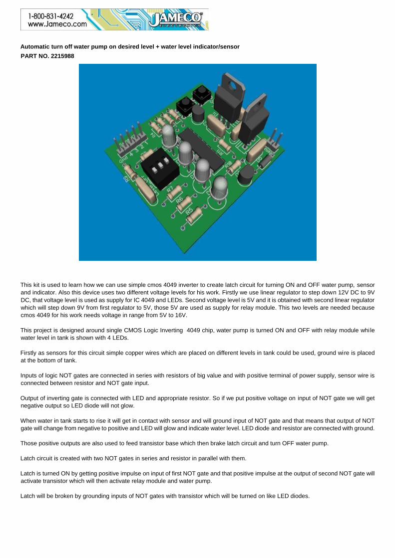
Automatic turn off water pump on desired level + water level indicator/sensor
PART NO. 2215988
This kit is used to learn how we can use simple cmos 4049 inverter to create latch circuit for turning ON and OFF water pump, sensor
and indicator. Also this device uses two different voltage levels for his work. Firstly we use linear regulator to step down 12V DC to 9V
DC, that voltage level is used as supply for IC 4049 and LEDs. Second voltage level is 5V and it is obtained with second linear regulator
which will step down 9V from first regulator to 5V, those 5V are used as supply for relay module. This two levels are needed because
cmos 4049 for his work needs voltage in range from 5V to 16V.
This project is designed around single CMOS Logic Inverting 4049 chip, water pump is turned ON and OFF with relay module whi le
water level in tank is shown with 4 LEDs.
Firstly as sensors for this circuit simple copper wires which are placed on different levels in tank could be used, ground wire is placed
at the bottom of tank.
Inputs of logic NOT gates are connected in series with resistors of big value and with positive terminal of power supply, sensor wire is
connected between resistor and NOT gate input.
Output of inverting gate is connected with LED and appropriate resistor. So if we put positive voltage on input of NOT gate we will get
negative output so LED diode will not glow.
When water in tank starts to rise it will get in contact with sensor and will ground input of NOT gate and that means that output of NOT
gate will change from negative to positive and LED will glow and indicate water level. LED diode and resistor are connected with ground.
Those positive outputs are also used to feed transistor base which then brake latch circuit and turn OFF water pump.
Latch circuit is created with two NOT gates in series and resistor in parallel with them.
Latch is turned ON by getting positive impulse on input of first NOT gate and that positive impulse at the output of second NOT gate will
activate transistor which will then activate relay module and water pump.
Latch will be broken by grounding inputs of NOT gates with transistor which will be turned on like LED diodes.
If user wants to turn OFF water pump on different level (shown by LED) he can do that by activating DIP switch. To turn OFF pump on
first level user needs to slide first switch part ON to turn OFF pump on second level second part should be turned ON and to turn OFF
water pump on third level third part of dip switch should be turned ON (only one part of switch must be turned ON at the same time).
To turn OFF water pump on last level all parts of dip switch must be OFF.
Device is connected with relay module using jumper wires. Device gives +5V when water pump should work, those 5V are used to turn
ON relay module.
Relay module is used because it is much safer then user side soldered relay on PCB, but still all safety measures should be done!!
Incorrect wiring can cause damage to appliances or more importantly, yourself!
Time required: 5 Hours depending on experience
Experience Level: Intermediate
Required tools and parts: 1 12V DC power supply 2. Soldering iron
3. Solder
4. Jumper wires for connecting relay module and board
5. Small snips
Bill of Materials:
Qty Jameco SKU Component Name
1 13055 4049 HEX INVERTING BUFFER/CONVERTER
2 38359 Q1, Q2 - Transistor 2N3904 NPN General Purpose
6 690689 R5, R6, R7, R8, R9, R10 - Resistor Carbon Film 180 Ohm 1/4 Watt 5%
4 resistors for LED diodes and 3 for BC547B bases.
5 691657 R1, R2, R3, R4, R11 Resistor Carbon Film 2.2m Ohm 1/4 Watt 5%
3 25540 C1, C2, C5 - .22 uF 50 Volt Monolithic Capacitor
2 153252 ON, OFF - Single Pole Single Throw Off Momentary On 12 Volt DC @ 150 mA Tactile Pushbutton Switch
1 2260842 Relay Module
1 103393 Sensors, supply, relay - HEADER,STRAIGHT MALE,1 ROW,10PIN,.1 INCH CTR,.025 INCH PST,.23 INCH GLDTL
Two pins for supply (12V).
Two pins for relay module (5V).
Five pins for sensors.
4 333973 D1, D2, D3, D4 - LED Uni-Color Red 660nm 2-Pin
1 51262 U2 - Standard Regulator 5 Volt 1 Amp
2 151116 C3, C4 - 0.1 uF 25 Volt 20% Ceramic
1 206359 level off - 3 POSITION 6 PIN SINGLE POLE SINGLE THROW STANDARD RAISED SLIDE DIP SWITCH
1 876352 U1 - Standard Regulator 9 Volt
1 179215 D5 - Diode Switching 100 Volt 0.3A 2-Pin DO-35
1 37372 Socket IC 16 Pin Soldertail Low Profile Single Wipe
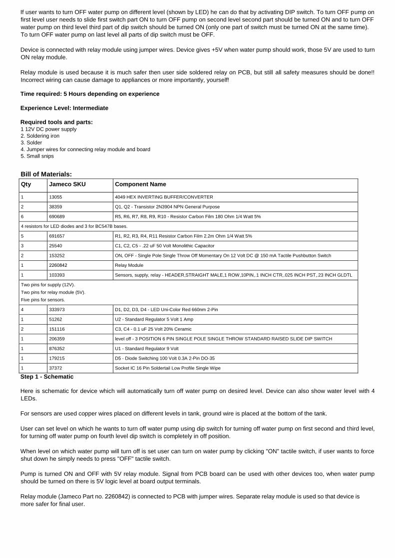
Step 1 - Schematic
Here is schematic for device which will automatically turn off water pump on desired level. Device can also show water level with 4
LEDs.
For sensors are used copper wires placed on different levels in tank, ground wire is placed at the bottom of the tank.
User can set level on which he wants to turn off water pump using dip switch for turning off water pump on first second and third level,
for turning off water pump on fourth level dip switch is completely in off position.
When level on which water pump will turn off is set user can turn on water pump by clicking "ON" tactile switch, if user wants to force
shut down he simply needs to press "OFF" tactile switch.
Pump is turned ON and OFF with 5V relay module. Signal from PCB board can be used with other devices too, when water pump
should be turned on there is 5V logic level at board output terminals.
Relay module (Jameco Part no. 2260842) is connected to PCB with jumper wires. Separate relay module is used so that device is
more safer for final user.
Incorrect wiring can cause damage to appliances or more importantly, yourself!
It is advised that user check delivered parts and see if DIY kit contains all necessary parts. Due to inventory packaging methods, you
may receive extra components for some products.
Kit assembling should be done in safe environment without strong humidity and on fireproof bench.
*** Disclaimer: This kit is meant to operate with equipment such as line operated water pumps or motor starter relays and/or
contactors at lower control voltages. Line voltage is dangerous and if mishandled can cause injury or death. If you are not familiar or
have not worked with line operated equipment, have a licensed electrician do the power wiring for you. This kit is meant to be
educational in nature and can be used with line operated equipment if National Electric Code guidelines are followed. ***
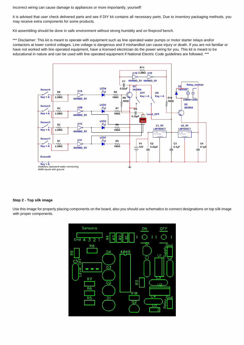
Step 2 - Top silk image
Use this image for properly placing components on the board, also you should use schematics to connect designations on top silk image
with proper components.
Step 3 - Resistors
Resistor is a passive component used to control current in a circuit. Its resistance is given by the ratio of voltage applied across its
terminals to the current passing through it. Thus a particular value of resistor, for fixed voltage, limits the current through it. They are
omnipresent in electronic circuits.
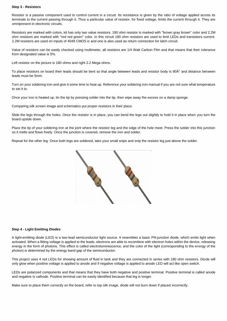
Resistors are marked with colors, kit has only two value resistors. 180 ohm resistor is marked with "brown gray brown" color and 2.2M
ohm resistors are marked with "red red green" color. In this circuit 180 ohm resistors are used to limit LEDs and transistors current.
2.2M resistors are used on inputs of 4049 CMOS ic and one is also used as return connection for latch circuit.
Value of resistors can be easily checked using multimeter, all resistors are 1/4 Watt Carbon Film and that means that their tolerance
from designated value is 5%.
Left resistor on the picture is 180 ohms and right 2.2 Mega ohms.
To place resistors on board their leads should be bent so that angle between leads and resistor body is 90° and distance between
leads must be 5mm.
Turn on your soldering iron and give it some time to heat up. Reference your soldering iron manual if you are not sure what temperature
to set it to.
Once your iron is heated up, tin the tip by pressing solder into the tip, then wipe away the excess on a damp sponge.
Comparing silk screen image and schematics put proper resistors in their place.
Slide the legs through the holes. Once the resistor is in place, you can bend the legs out slightly to hold it in place when you turn the
board upside down.
Place the tip of your soldering iron at the joint where the resistor leg and the edge of the hole meet. Press the solder into this junction
so it melts and flows freely. Once the junction is covered, remove the iron and solder.
Repeat for the other leg. Once both legs are soldered, take your small snips and snip the resistor leg just above the solder.
Step 4 - Light Emitting Diodes
A light-emitting diode (LED) is a two-lead semiconductor light source. It resembles a basic PN-junction diode, which emits light when
activated. When a fitting voltage is applied to the leads, electrons are able to recombine with electron holes within the device, releasing
energy in the form of photons. This effect is called electroluminescence, and the color of the light (corresponding to the energy of the
photon) is determined by the energy band gap of the semiconductor.
This project uses 4 red LEDs for showing amount of fluid in tank and they are connected in series with 180 ohm resistors. Diode will
only glow when positive voltage is applied to anode and if negative voltage is applied to anode LED will act like open switch.
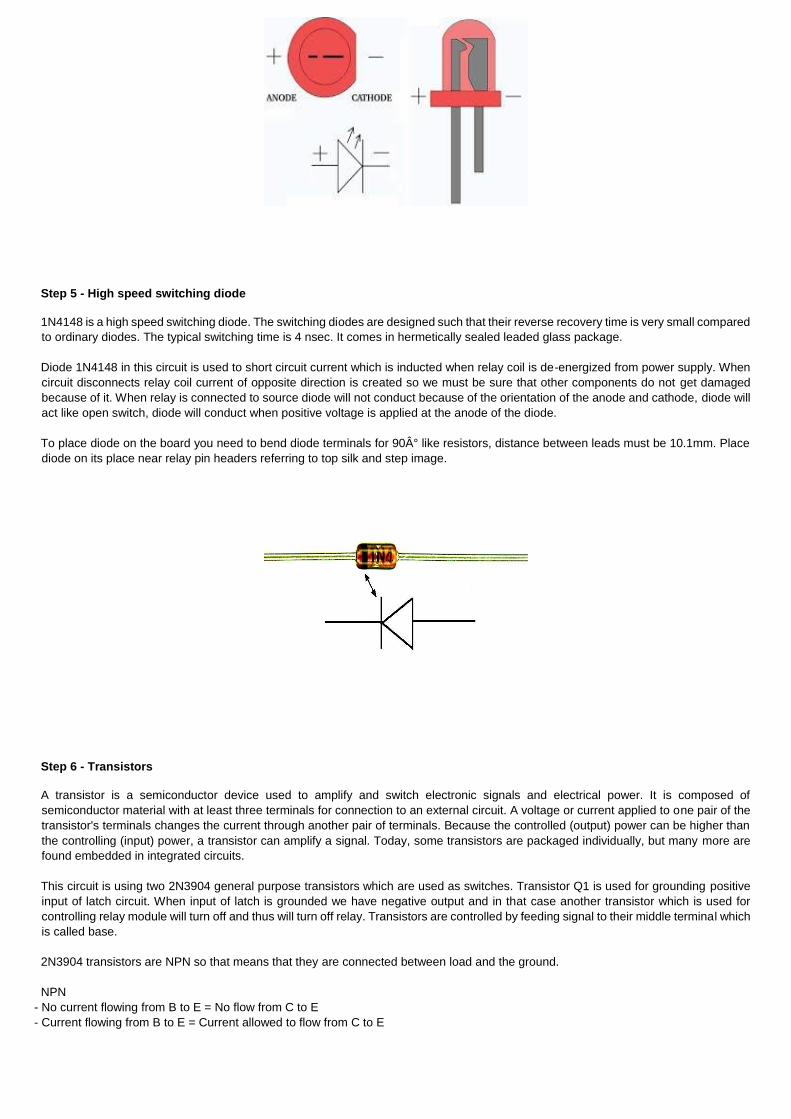
LEDs are polarized components and that means that they have both negative and positive terminal. Positive terminal is called anode
and negative is cathode. Positive terminal can be easily identified because that leg is longer.
Make sure to place them correctly on the board, refer to top silk image, diode will not burn down if placed incorrectly.
Step 5 - High speed switching diode
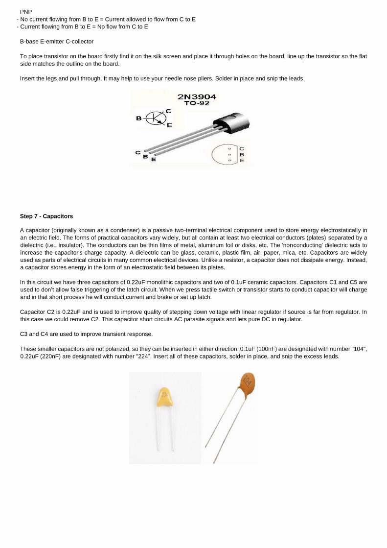
1N4148 is a high speed switching diode. The switching diodes are designed such that their reverse recovery time is very small compared
to ordinary diodes. The typical switching time is 4 nsec. It comes in hermetically sealed leaded glass package.
Diode 1N4148 in this circuit is used to short circuit current which is inducted when relay coil is de-energized from power supply. When
circuit disconnects relay coil current of opposite direction is created so we must be sure that other components do not get damaged
because of it. When relay is connected to source diode will not conduct because of the orientation of the anode and cathode, diode will
act like open switch, diode will conduct when positive voltage is applied at the anode of the diode.
To place diode on the board you need to bend diode terminals for 90° like resistors, distance between leads must be 10.1mm. Place
diode on its place near relay pin headers referring to top silk and step image.
Step 6 - Transistors
A transistor is a semiconductor device used to amplify and switch electronic signals and electrical power. It is composed of
semiconductor material with at least three terminals for connection to an external circuit. A voltage or current applied to one pair of the
transistor's terminals changes the current through another pair of terminals. Because the controlled (output) power can be higher than
the controlling (input) power, a transistor can amplify a signal. Today, some transistors are packaged individually, but many more are
found embedded in integrated circuits.
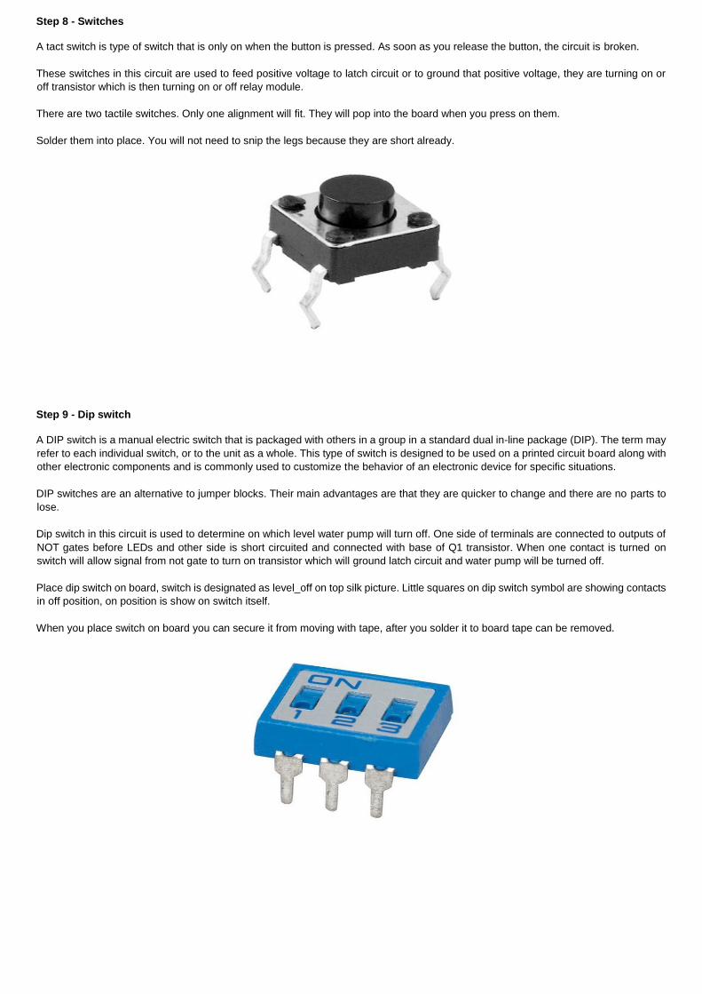
This circuit is using two 2N3904 general purpose transistors which are used as switches. Transistor Q1 is used for grounding positive
input of latch circuit. When input of latch is grounded we have negative output and in that case another transistor which is used for
controlling relay module will turn off and thus will turn off relay. Transistors are controlled by feeding signal to their middle terminal which
is called base.
2N3904 transistors are NPN so that means that they are connected between load and the ground.
NPN
- No current flowing from B to E = No flow from C to E
- Current flowing from B to E = Current allowed to flow from C to E
PNP
- No current flowing from B to E = Current allowed to flow from C to E
- Current flowing from B to E = No flow from C to E
B-base E-emitter C-collector
To place transistor on the board firstly find it on the silk screen and place it through holes on the board, line up the transistor so the flat
side matches the outline on the board.
Insert the legs and pull through. It may help to use your needle nose pliers. Solder in place and snip the leads.
Step 7 - Capacitors
A capacitor (originally known as a condenser) is a passive two-terminal electrical component used to store energy electrostatically in
an electric field. The forms of practical capacitors vary widely, but all contain at least two electrical conductors (plates) separated by a
dielectric (i.e., insulator). The conductors can be thin films of metal, aluminum foil or disks, etc. The 'nonconducting' dielectric acts to
increase the capacitor's charge capacity. A dielectric can be glass, ceramic, plastic film, air, paper, mica, etc. Capacitors are widely
used as parts of electrical circuits in many common electrical devices. Unlike a resistor, a capacitor does not dissipate energy. Instead,
a capacitor stores energy in the form of an electrostatic field between its plates.
In this circuit we have three capacitors of 0.22uF monolithic capacitors and two of 0.1uF ceramic capacitors. Capacitors C1 and C5 are
used to don’t allow false triggering of the latch circuit. When we press tactile switch or transistor starts to conduct capacitor will charge
and in that short process he will conduct current and brake or set up latch.
Capacitor C2 is 0.22uF and is used to improve quality of stepping down voltage with linear regulator if source is far from regulator. In
this case we could remove C2. This capacitor short circuits AC parasite signals and lets pure DC in regulator.
C3 and C4 are used to improve transient response.
These smaller capacitors are not polarized, so they can be inserted in either direction, 0.1uF (100nF) are designated with number "104",
0.22uF (220nF) are designated with number "224”. Insert all of these capacitors, solder in place, and snip the excess leads.
Step 8 - Switches
A tact switch is type of switch that is only on when the button is pressed. As soon as you release the button, the circuit is broken.
These switches in this circuit are used to feed positive voltage to latch circuit or to ground that positive voltage, they are turning on or
off transistor which is then turning on or off relay module.
There are two tactile switches. Only one alignment will fit. They will pop into the board when you press on them.
Solder them into place. You will not need to snip the legs because they are short already.
Step 9 - Dip switch
A DIP switch is a manual electric switch that is packaged with others in a group in a standard dual in-line package (DIP). The term may
refer to each individual switch, or to the unit as a whole. This type of switch is designed to be used on a printed circuit board along with
other electronic components and is commonly used to customize the behavior of an electronic device for specific situations.
DIP switches are an alternative to jumper blocks. Their main advantages are that they are quicker to change and there are no parts to
lose.
Dip switch in this circuit is used to determine on which level water pump will turn off. One side of terminals are connected to outputs of
NOT gates before LEDs and other side is short circuited and connected with base of Q1 transistor. When one contact is turned on
switch will allow signal from not gate to turn on transistor which will ground latch circuit and water pump will be turned off.
Place dip switch on board, switch is designated as level_off on top silk picture. Little squares on dip switch symbol are showing contacts
in off position, on position is show on switch itself.
When you place switch on board you can secure it from moving with tape, after you solder it to board tape can be removed.
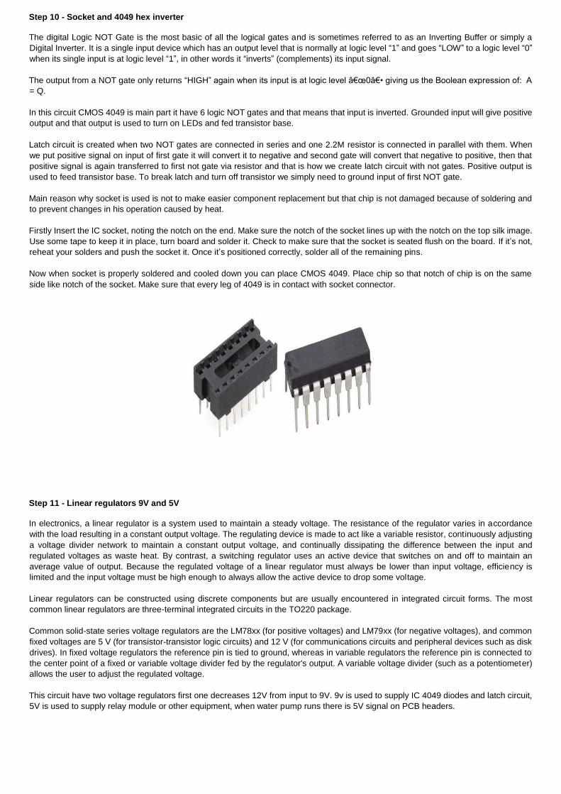
Step 10 - Socket and 4049 hex inverter
The digital Logic NOT Gate is the most basic of all the logical gates and is sometimes referred to as an Inverting Buffer or simply a
Digital Inverter. It is a single input device which has an output level that is normally at logic level “1” and goes “LOW” to a logic level “0”
when its single input is at logic level “1”, in other words it “inverts” (complements) its input signal.
The output from a NOT gate only returns “HIGH” again when its input is at logic level “0― giving us the Boolean expression of: A
= Q.
In this circuit CMOS 4049 is main part it have 6 logic NOT gates and that means that input is inverted. Grounded input will give positive
output and that output is used to turn on LEDs and fed transistor base.
Latch circuit is created when two NOT gates are connected in series and one 2.2M resistor is connected in parallel with them. When
we put positive signal on input of first gate it will convert it to negative and second gate will convert that negative to positive, then that
positive signal is again transferred to first not gate via resistor and that is how we create latch circuit with not gates. Positive output is
used to feed transistor base. To break latch and turn off transistor we simply need to ground input of first NOT gate.
Main reason why socket is used is not to make easier component replacement but that chip is not damaged because of soldering and
to prevent changes in his operation caused by heat.
Firstly Insert the IC socket, noting the notch on the end. Make sure the notch of the socket lines up with the notch on the top silk image.
Use some tape to keep it in place, turn board and solder it. Check to make sure that the socket is seated flush on the board. If it’s not,
reheat your solders and push the socket it. Once it’s positioned correctly, solder all of the remaining pins.
Now when socket is properly soldered and cooled down you can place CMOS 4049. Place chip so that notch of chip is on the same
side like notch of the socket. Make sure that every leg of 4049 is in contact with socket connector.
Step 11 - Linear regulators 9V and 5V
In electronics, a linear regulator is a system used to maintain a steady voltage. The resistance of the regulator varies in accordance
with the load resulting in a constant output voltage. The regulating device is made to act like a variable resistor, continuously adjusting
a voltage divider network to maintain a constant output voltage, and continually dissipating the difference between the input and
regulated voltages as waste heat. By contrast, a switching regulator uses an active device that switches on and off to maintain an
average value of output. Because the regulated voltage of a linear regulator must always be lower than input voltage, efficiency is
limited and the input voltage must be high enough to always allow the active device to drop some voltage.
Linear regulators can be constructed using discrete components but are usually encountered in integrated circuit forms. The most
common linear regulators are three-terminal integrated circuits in the TO220 package.
Common solid-state series voltage regulators are the LM78xx (for positive voltages) and LM79xx (for negative voltages), and common
fixed voltages are 5 V (for transistor-transistor logic circuits) and 12 V (for communications circuits and peripheral devices such as disk
drives). In fixed voltage regulators the reference pin is tied to ground, whereas in variable regulators the reference pin is connected to
the center point of a fixed or variable voltage divider fed by the regulator's output. A variable voltage divider (such as a potentiometer)
allows the user to adjust the regulated voltage.
This circuit have two voltage regulators first one decreases 12V from input to 9V. 9v is used to supply IC 4049 diodes and latch circuit,
5V is used to supply relay module or other equipment, when water pump runs there is 5V signal on PCB headers.
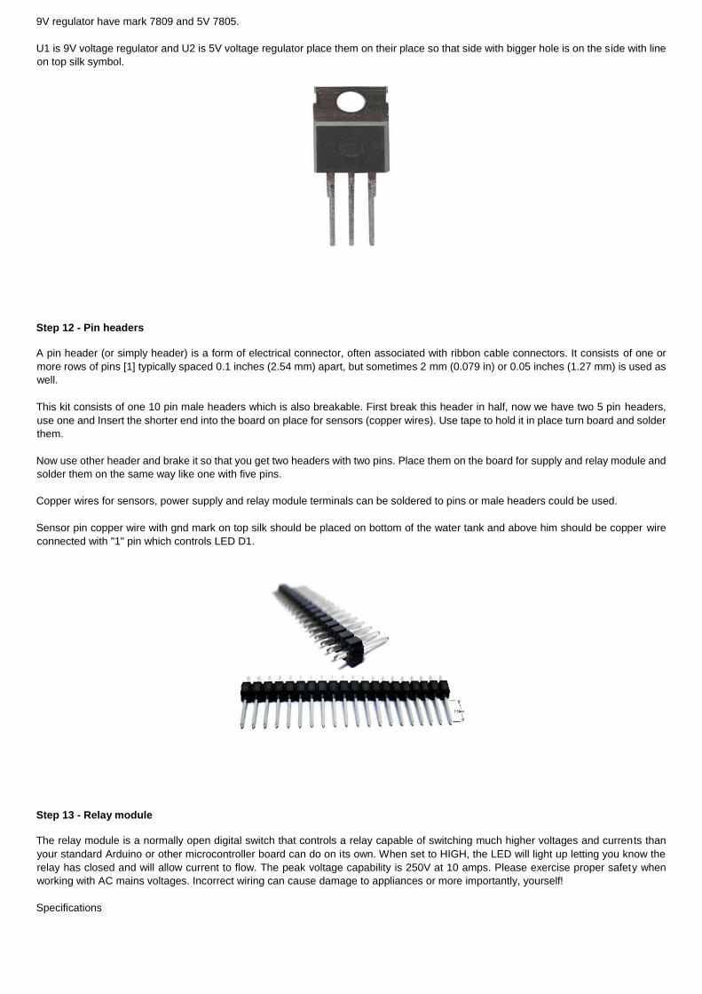
9V regulator have mark 7809 and 5V 7805.
U1 is 9V voltage regulator and U2 is 5V voltage regulator place them on their place so that side with bigger hole is on the side with line
on top silk symbol.
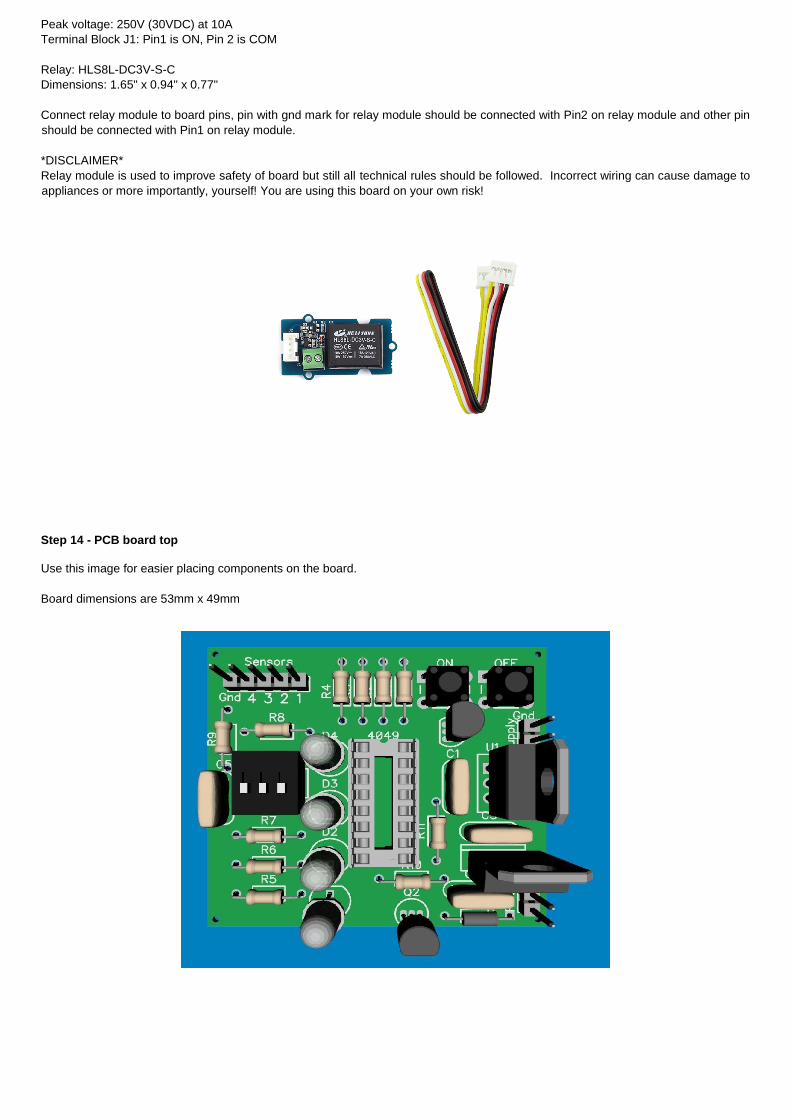
Step 12 - Pin headers
A pin header (or simply header) is a form of electrical connector, often associated with ribbon cable connectors. It consists of one or
more rows of pins [1] typically spaced 0.1 inches (2.54 mm) apart, but sometimes 2 mm (0.079 in) or 0.05 inches (1.27 mm) is used as
well.
This kit consists of one 10 pin male headers which is also breakable. First break this header in half, now we have two 5 pin headers,
use one and Insert the shorter end into the board on place for sensors (copper wires). Use tape to hold it in place turn board and solder
them.
Now use other header and brake it so that you get two headers with two pins. Place them on the board for supply and relay module and
solder them on the same way like one with five pins.
Copper wires for sensors, power supply and relay module terminals can be soldered to pins or male headers could be used.
Sensor pin copper wire with gnd mark on top silk should be placed on bottom of the water tank and above him should be copper wire
connected with "1" pin which controls LED D1.
Step 13 - Relay module
The relay module is a normally open digital switch that controls a relay capable of switching much higher voltages and currents than
your standard Arduino or other microcontroller board can do on its own. When set to HIGH, the LED will light up letting you know the
relay has closed and will allow current to flow. The peak voltage capability is 250V at 10 amps. Please exercise proper safety when
working with AC mains voltages. Incorrect wiring can cause damage to appliances or more importantly, yourself!
Specifications
Peak voltage: 250V (30VDC) at 10A
Terminal Block J1: Pin1 is ON, Pin 2 is COM
Relay: HLS8L-DC3V-S-C
Dimensions: 1.65" x 0.94" x 0.77"
Connect relay module to board pins, pin with gnd mark for relay module should be connected with Pin2 on relay module and other pin
should be connected with Pin1 on relay module.
*DISCLAIMER*
Relay module is used to improve safety of board but still all technical rules should be followed. Incorrect wiring can cause damage to
appliances or more importantly, yourself! You are using this board on your own risk!
Step 14 - PCB board top
Use this image for easier placing components on the board.
Board dimensions are 53mm x 49mm
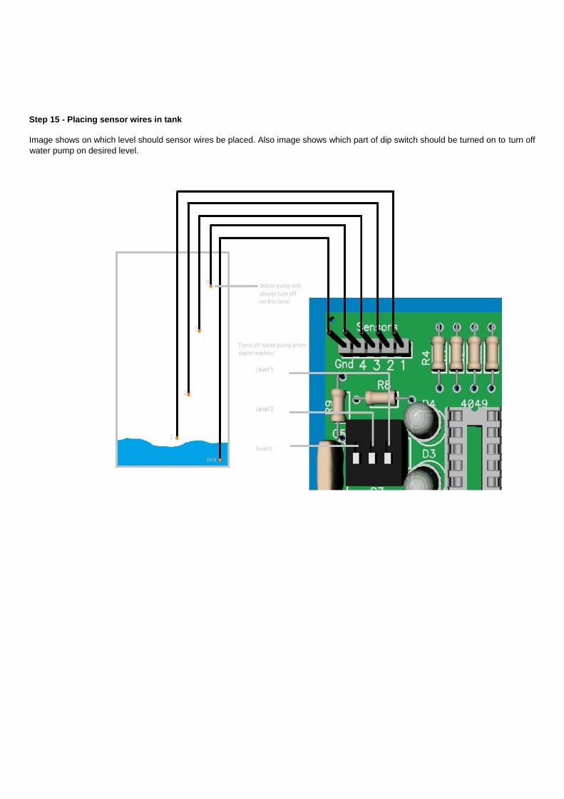
Step 15 - Placing sensor wires in tank
Image shows on which level should sensor wires be placed. Also image shows which part of dip switch should be turned on to turn off
water pump on desired level.