Embed Size (px)
Citation preview
AUTOMATIC VOLTAGE REGULATOR(AVR)
Automatic voltage regulator (AVR) maintains the Generator terminal voltage at a given value automatically by changing the excitation current to the Generator field.
The AVR supplies the required D.C. to the Generator field depending on the load, power factor etc. to maintain a constant terminal voltage.
1
CONTROL SYSTEMS OF AVR
1. Auto control
2. Manual control
2
TYPES OF AVR
1.Single channel AVR
Two controllers one is automatic and the other is manual
Both the controllers are fed from the same supply
3
2. Dual channel AVR system One automatic voltage controller
and one manual controller Different power supply, gate
control and pulse amplifier units for each of the controllers
4
3.Twin channel AVR system
Two automatic voltage regulators
5
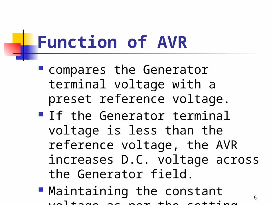
Function of AVR compares the Generator terminal
voltage with a preset reference voltage.
If the Generator terminal voltage is less than the reference voltage, the AVR increases D.C. voltage across the Generator field.
Maintaining the constant voltage as per the setting.
6
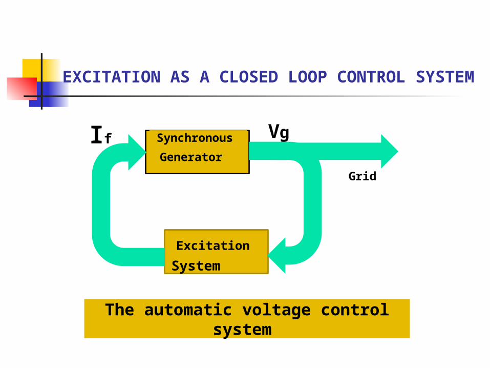
The automatic voltage control system
EXCITATION AS A CLOSED LOOP CONTROL SYSTEM
Grid
If Vg Synchronous
Generator
Excitation
System
2
3
4
7
6
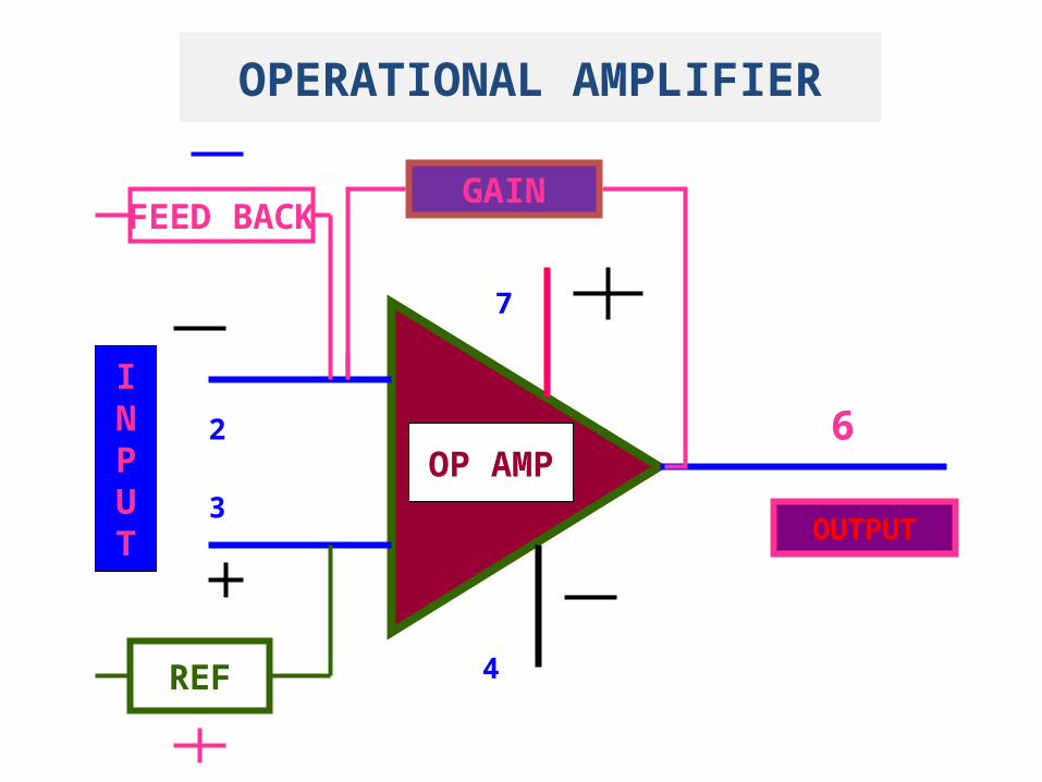
GAIN
INPUT OUTPUT
OP AMP
REF
FEED BACK
OPERATIONAL AMPLIFIER
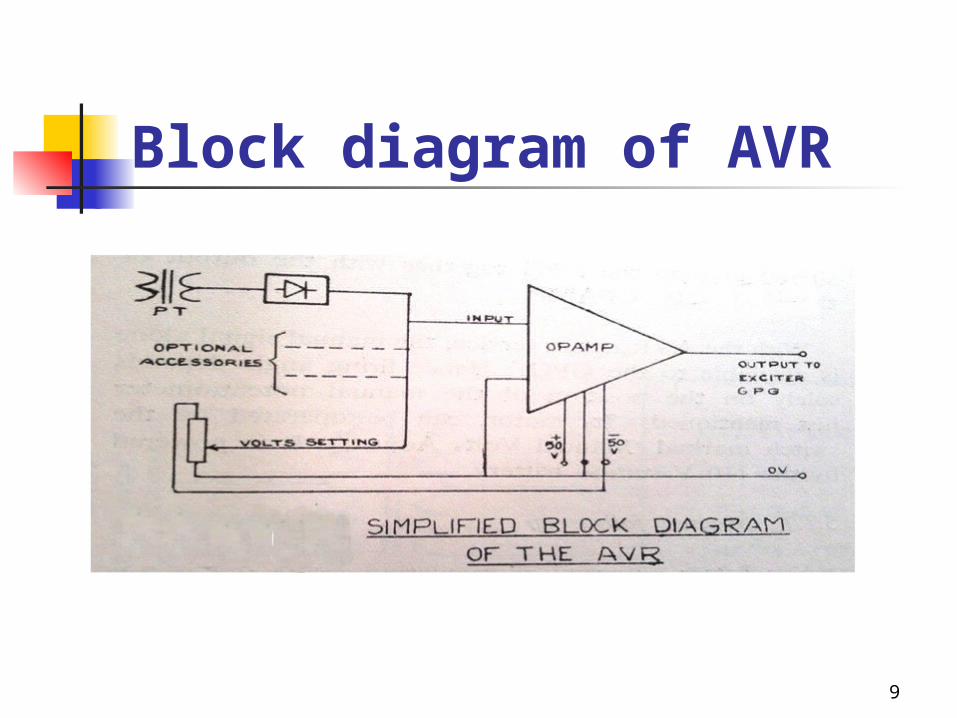
Block diagram of AVR
9
AVR inputs Generator voltage feedback signal Generator voltage reference AVR provides the following
functions and signals Summing and amplification of signals to
provide the exciter rectifier firing angle control signal.
A signal for manual follow up.
10
AVR Action Two inputs are of opposite polarity. When the magnitudes are equal,
the net input is zero. When unequal-the error is
amplified and reversed to obtain a correction signal which goes to the
GPG(gate pulse generator)
11
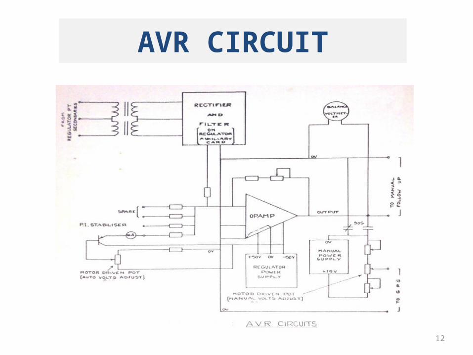
AVR CIRCUIT
12
+-50 V SUPPLY To power the regulator amplifier as
well as the optional accessories such as manual follow up and power integral stabilizer
13
Regulator auxiliary card 3 phase voltage from the generator
PT’s are stepped down and applied to the regulator auxiliary card which converts it to ripple free dc voltage suitable for the input of regulator amplifier.
Balance Voltmeter
A 30-0-30 V dc voltmeter is connected across the output of regulator amplifier to read the magnitude and polarity of the output voltage of OP-AMP at any instant.
AVR Voltage Setting
From the +-50 V source ,-50 V is applied and taken across a motorized potentiometer which can be operated from the control bench board. The variable output from the pot. is applied to the input of the regulator OP-AMP.
Manual Voltage Control In the absence of AVR the voltage
can be manually controlled. The stabilized 15 V from the MPS is
applied across a second potentiometer. The variable output goes to the GPG together with output of the regulator
OP-AMP.
MANUAL FOLLOW UP
When there is a noticeable output from the regulator OP-AMP, depending on its polarity, either of a pair of relays is automatically closed to drive the manual potentiometer motor in the required direction.
![[PPT]PowerPoint Presentation - 123seminarsonly.com · Web viewAUTOMATIC VOLTAGE REGULATOR(AVR) Automatic voltage regulator (AVR) maintains the Generator terminal voltage at a given](https://img.pdfslide.net/doc/110x75/5afbd37a7f8b9a944d8b547e/pptpowerpoint-presentation-viewautomatic-voltage-regulatoravr-automatic-voltage.jpg)