Embed Size (px)
Citation preview
TECHNICAL CONTRIBUTION
Autonomous Navigation for On-Orbit Servicing
Heike Benninghoff • Toralf Boge • Florian Rems
Received: 11 September 2013 / Accepted: 27 February 2014 / Published online: 19 March 2014
� Springer-Verlag Berlin Heidelberg 2014
Abstract On-orbit servicing missions induce challenges
for the rendezvous and docking system since a typical
target satellite is not specially prepared for such a mission,
can be partly damaged or even freely tumbling with lost
attitude control. In contrast to manned spaceflight or for-
mation flying missions, new sensors and algorithms have to
be designed for relative navigation. Dependent on the
distance to the target, optical sensors such as mono and
stereo cameras as well as 3D sensors like laser scanners can
be employed as rendezvous sensors. Navigation methods
for far and close range and different verification methods
are discussed.
Keywords On-orbit servicing � Visual navigation �Autonomous rendezvous � Image processing � Non-
cooperative target � Pose estimation
1 Introduction
Future on-orbit servicing missions aim at satellite lifetime
extension or safe end-of-life de-orbiting of a non-cooper-
ative, passive target [8, 19, 25, 31]. A typical target
satellite can be affected by some damage, can have a non-
operational orbit and attitude control or can be out of fuel.
The idea of on-orbit servicing can be tracked back to 1987,
when TV-Sat 1 was launched and a failure of one of the
solar panels terminated the mission since all attempts to
repair the satellite from ground had failed. By approaching
and docking to the target satellite with a servicing satellite
and by performing service tasks like refueling, deployment
of solar arrays or the take over of orbit and attitude control,
the lifetime of a partly damaged satellite could be extended
in the future.
At the end of a satellite’s lifetime, it is necessary to de-
orbit it, i.e. to perform a re-entry in the Earth’s atmosphere
or to bring the satellite to a graveyard orbit. If the satellite
is damaged, if there is no control of its orbit and attitude or
if the communication with the satellite fails, a de-orbiting
can be performed using a small service satellite. The ser-
vicer approaches the target satellite in its orbit, captures it
with a docking tool or a robotic arm, rigidly connects with
the target, and takes over its orbit and attitude control
followed by a de-orbiting in the coupled configuration.
Alternative strategies for on-orbit servicing and active
space debris removal are among others the concept of
deploying a net to capture an in-operative satellite or the
Ion Beam Shepherd concept [5], where a target spacecraft
should be de-orbited without physical contact between the
two satellites.
On-orbit servicing therefore contributes to space debris
removal since non-operational, eventually free-tumbling
target satellites in possibly strategic low Earth orbits or in
the geostationary orbit are risks for other active and oper-
ational satellites and for manned spaceflight. As space
debris is a critical issue, concepts for active debris removal
have to be developed [19].
While rendezvous and docking are state of the art in
manned spaceflight (e.g. docking to the ISS with supply
vehicles), new challenges arise in the on-orbit servicing
context. First, a typical target satellite is not specially
prepared for rendezvous and docking in contrast to the ISS.
There are no reflectors or markers which can be used for
navigation and there is no docking or capturing equipment.
Second, the target can have lost its orbit and attitude
H. Benninghoff (&) � T. Boge � F. Rems
German Space Operations Center, German Aerospace Center
(DLR), 82234 Weßling, Germany
e-mail: [email protected]
123
Kunstl Intell (2014) 28:77–83
DOI 10.1007/s13218-014-0297-0
control. A freely tumbling target impedes a safe approach
and docking since its movement is not easy to predict.
Third, there is no communication between the two satel-
lites and no precise knowledge of the target’s position and
orientation in contrast to formation flying missions. The
mentioned properties define the term non-cooperative
target.
In our work, we focus on autonomous rendezvous with
no or limited ground intervention. Data of sensors mounted
on the service satellite should be processed on-board and
the entire guidance, navigation and control algorithm has to
be computed by the on-board computer of the servicer. The
autonomy requirement therefore poses a further challenge
on the rendezvous control system.
As a consequence, new concepts and methods compared
to manned spaceflight and formation flying missions have
to be developed for safe rendezvous and docking to the
target in an on-orbit servicing mission. Several studies and
developments have been proposed in the literature. In [14],
a concept called SMART-OLEV is presented for lifetime
extension for geostationary spacecrafts. A space debris
removal method using a small satellite is proposed in [19].
The German Space Operations Center (DLR-GSOC) has
executed a far range rendezvous experiment in the exten-
ded phase of the PRISMA mission [6]. Additionally, sev-
eral works on satellite tracking, guidance, navigation and
control algorithms, as well as coordinated plan and control
of the space robot are conducted by various authors, cf. [7,
18, 21, 22, 24, 27, 30] to mention a few.
In this work, only the rendezvous phase is considered.
The objective of this paper is to provide an overview on
technologies and concepts for autonomous relative navi-
gation developed at the German Space Operations Center.
2 Methods
2.1 Sensors for Autonomous Navigation
For an on-orbit servicing mission, sensors are needed to
estimate the relative position and orientation (pose)
between service and target satellite. Optical sensors like i.a.
mono and stereo camera systems or 3D sensors such as
LIDARs and RADARs (LIght/ RAdio Detection And
Ranging) are suitable sensors for pose estimation during
the rendezvous to a non-cooperative target spacecraft. Also
PMD (photonic mixing device) cameras are theoretical
candidates; however, to the authors’ knowledge, PMD
sensors have never been used in space yet.
We employ monocular cameras for far range rendez-
vous [2, 6]. While tracking a satellite from far range
camera images, we already know a rough direction to the
target. A camera with a high resolution (e.g. 1,024 9 1,024
pixels) and a small field of view (e.g. 10� 9 10�) has to be
chosen such that the number of pixels per degree is large.
This is important to dissolve the target’s projection in the
image plane. Otherwise, the image of the target at several
kilometers distance would cover only a very small fraction
of a pixel and the target would not be visible.
Further attention has to be drawn concerning the sensi-
tivity of the camera. The magnitude of sunlight reflected by
the target satellite decreases quadratically with the distance
to the target. The light of the stars can be even some
magnitudes smaller. The visibility of stars will be impor-
tant if the direction to the target in an inertial reference
system is estimated using data of a star catalog, see
Sect. 2.2.1. Therefore, the aperture diameter and the
exposure time need to be chosen or set large enough
dependent on the operational range such that visibility of
target and stars is ensured. During far range rendezvous,
not the full 6D pose (relative position and orientation)
needs to be estimated. We compute the direction to the
target, denoted as line-of-sight, from sensor data, cf. [2, 6].
At mid and close range, mono cameras with a larger
field of view can be used. At close range, stereo cameras
can be employed resulting in a more accurate pose esti-
mation. In the VIBANASS project [18], a camera system
was developed for far, mid and close range rendezvous. For
ranges [5 m, a monocular camera was used, whereas a
stereo camera was chosen for the last five meters prior to
docking. Both cameras are based on a CMOS chip. 3D
sensors like i.a. LIDARs or PMD cameras generate a 3D
point cloud with distance information and are possible
alternatives to standard cameras at mid and close range.
The full 6D information about the relative position and
orientation needs to be computed at mid and close range.
Standard 2D cameras (CCD/CMOS camera) and 3D sen-
sors (PMD camera, LIDAR, RADAR) serve as appropriate
sensors. Naturally, 3D laser scanners result in a high
accurate distance determination. Lateral motions can be
tracked with high accuracy if a visual camera with high
resolution is employed. Further, visual cameras allow to
detect and track edges of the spacecraft, textured surfaces
or LEDs. The performance of all optical sensors strongly
depends on illumination conditions. Cameras require suf-
ficient brightness which depends on factors such as the
surface material of the target, the incident angle of the Sun
and the observation angle, the size of the target and the
range between the two spacecrafts. The performance of
LIDAR sensors, for example, will severely degrade if high
reflective surfaces (like MLI surfaces) are involved.
The methods described in the following sections are
based on our research on camera navigation. Visual cam-
eras are attractive solutions regarding low weight and low
power-consumption. Further, many spacecrafts are already
equipped with star trackers. Dependent on their location
78 Kunstl Intell (2014) 28:77–83
123
and orientation w.r.t. the spacecraft, they can be addition-
ally employed as far range rendezvous sensor.
2.2 Navigation Methods and Algorithm Design
In this section, we propose methods for relative navigation
which are based on research conducted at DLR-GSOC [1–
3]. We distinguish between far range rendezvous and mid/
close range rendezvous since different objectives and tasks
exist and thus different methods and algorithms are chosen
and developed.
2.2.1 Far Range Rendezvous
The navigation part at ranges[500 m between servicer and
target can be divided in two main steps: (1) Far range
image processing and (2) estimation of the relative orbital
elements by a navigation filter. For the latter, the method of
angles-only navigation [29] can be applied, see also [6].
We do not recall this concept, but concentrate on the image
processing part to measure the line-of-sight to the target
from monocular camera images which is an important
input to the navigation filter.
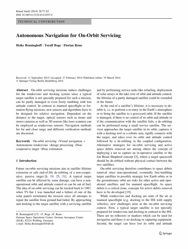
An image captured with a far range camera consists of a
black background and small bright spots. These clusters of
bright pixels can be stars, the target illuminated by sun-
light, or camera noise or hot spots, see Fig. 1. Hot spots are
pixels which look much brighter because they do not react
proportional to incoming light. The pixels are called hot
because the effect is increasing at high temperature.
Considering one single camera image, one can hardly
distinguish between stars, target or hot spots. In [2], we
developed an algorithm for far range image processing.
The idea of our method is to identify clusters in a given
image, to link clusters between two successive images and
to track them over a sequence of images. Considering the
velocity of the clusters in the 2D image, the target is
identified by motion segmentation: Its motion differs from
the motion of static hot spots and distant stars. In the image
domain, the star clusters have approximately the same
velocity vector, which depends on the attitude change of
the servicer. The motion segmentation is combined with a
star catalog. From the measured 2D position of the clusters
and the attitude of the camera with respect to an inertial
reference system (e.g. Equator J2000), the 3D direction
vector in the inertial reference system is computed and
compared to the true direction of stars given by the star
catalog. Thus, some of the clusters are assigned as stars and
the number of possible target candidates is thus decreased.
Inputs to the far range image processing are the current
image and the current attitude of the servicer on assump-
tion that a rough estimate of the orientation of the camera
with respect to the servicer’s body frame is known. An on-
line calibration resulting in a more accurate attitude esti-
mation of the camera is performed by the developed image
processing software which applies the q-method of
Wertz [28]. If the velocity of the servicer is additionally
available, the estimation of the line-of-sight vector to the
target is improved by performing an aberration correction.
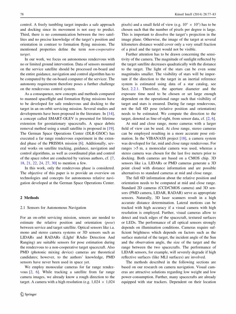
An overview on the single functions and their relation,
inputs and outputs of the system is presented in Fig. 2. For
details on the algorithm, resulting performance and accu-
racy, we refer to [2].
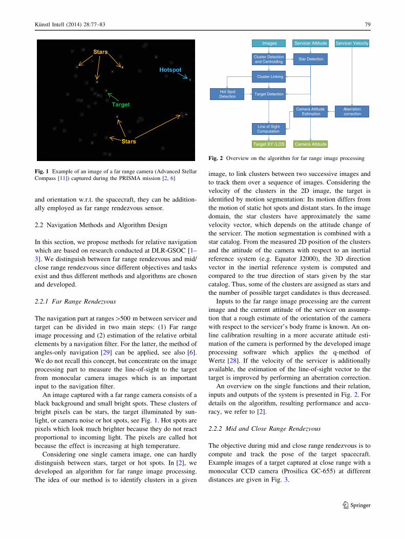
2.2.2 Mid and Close Range Rendezvous
The objective during mid and close range rendezvous is to
compute and track the pose of the target spacecraft.
Example images of a target captured at close range with a
monocular CCD camera (Prosilica GC-655) at different
distances are given in Fig. 3.
Fig. 1 Example of an image of a far range camera (Advanced Stellar
Compass [11]) captured during the PRISMA mission [2, 6]
Servicer Attitude Images
Cluster Detection and Centroiding
Cluster Linking
Hot Spot Detection
Star Detection
Target Detection
Line of Sight Computation
Camera Attitude Estimation
Target XY /LOS Camera Attitude
Servicer Velocity
Aberration correction
Fig. 2 Overview on the algorithm for far range image processing
Kunstl Intell (2014) 28:77–83 79
123
In a first step, the target has to be identified in the given
image. Typically, edge tracking algorithms, which track
the outer edges of the target or inner edges like the nozzle
boundary, are applied. For this task, images from mono and
stereo cameras are employed [3, 20, 26], where the detailed
algorithm depends on the sensor type. Also 3D sensors can
be used [3, 10, 23].
After identification of the target the full 6D pose has to
be estimated. We assume that information about the
geometry and sizes of the target is available, to relate
measurements in the sensor coordinate system with 3D/6D
quantities in a world coordinate system. The transformation
from the 6D pose vector to image/sensor coordinates is
described by a camera model or in general by a sensor
model.
In principle, there are two ways of re-computing the full
6D pose information: One way is to solve an inverse
problem. This can be combined with a least squares fit to
estimate the optimal pose such that mean square error
between real measurements and mappings of the pose via
the sensor model is minimized. Since non-linear models are
typically involved, the Levenberg–Marquardt algo-
rithm [16, 17] can be applied [26]. A second way is to use
an Extended Kalman filter or Unscented Kalman filter [12,
13, 15, 32], which incorporates the measurements in the
filter update/ correction step. We pursued this approach
in [1], where also more details on the vision system and on
the navigation and control method are given. Using Kal-
man filter techniques, the resulting pose estimation is much
smoother compared to pure sensor measurements, see
Sect. 3.1. Further, also quantities like the relative velocity
or angular rate of the target can be estimated simulta-
neously with the pose by a Kalman filter.
3 Verification
Before an on-orbit servicing mission can be launched,
rendezvous and docking sensors and algorithms have to be
intensively tested and verified. Software and hardware
tests, as well as complete hardware-in-the-loop tests can be
conducted. Further, the methods and concepts can be
demonstrated during real flight experiments with semi-
cooperative targets. Semi-cooperative means that we have
full control over a target satellite for safety reasons during
the demonstration, but only the data and information
present on board the service satellite is used for
rendezvous.
Each verification method has intrinsic advantages and
disadvantages. A combination of the verification methods
is recommended in the preparation phase of an on-orbit
servicing mission.
3.1 Hardware-in-the-Loop Simulator EPOS 2.0
The rendezvous and docking process including real hard-
ware like rendezvous sensors and the guidance, navigation
and control system can be verified within a hardware-in-
the-loop environment like the European Proximity Opera-
tions Simulator (EPOS 2.0). It is a robotic based test
facility for physical, real-time simulations of rendezvous
and docking maneuvers [4].
The testbed consists of two industrial manipulators with
each 6 degrees of freedom such that each robot can sim-
ulate the 6D dynamic behavior of a satellite in space. One
robot is mounted on a linear slide of 25 m length which
enables a simulation of the last 25 m of the rendezvous
phase and the contact dynamics simulation of the final
docking process. Using scaled models, simulation of larger
distances is also possible. The simulation of sunlight illu-
mination generates a realistic environmental scenario.
Another feature of the facility among others is the
dynamical capability which allows a high commanding rate
of 250 Hz, a prerequisite to perform contact dynamics
simulations. Recently, an extension to two endlessly
rotating axes has been implemented such that tumbling
target motions can be completely simulated.
We performed several hardware-in-the-loop simulations
using EPOS 2.0 for test and verification of complex real-
time embedded systems like rendezvous sensors [1]. The
Fig. 3 Example of images showing an illuminated target captured with a mono, CCD camera and marked detected edges (blue dots). (Color
figure online)
80 Kunstl Intell (2014) 28:77–83
123
embedded system was connected to its numerical coun-
terpart simulating the real environment of the sensor which
cannot be represented with real hardware (e.g. orbital
dynamics).
A typical closed loop testing scenario is as follows: A
rendezvous sensor is mounted on one robot of the test
facility which simulates the translational and rotational
motion of the service satellite. The second robot carries a
typical mock-up of a target satellite and simulates the
motion of the target satellite. The rendezvous sensor
measures the relative position and orientation between the
robots. The measurements are processed in real-time by
guidance, navigation and control algorithms which will
later run on the servicer’s on-board computer. A controller
computes commands for the thrusters and reaction wheels
based on the measurements, the navigation result and the
guidance values. The commands are fed to a real-time
numerical simulator which simulates the actuators and the
environment of the satellites. For the next sample, an
update of the state vector (position and orientation) is
computed using the control forces and torques as input
vectors for kinematic and dynamic equations of motions.
The robots of the EPOS facility move according to the
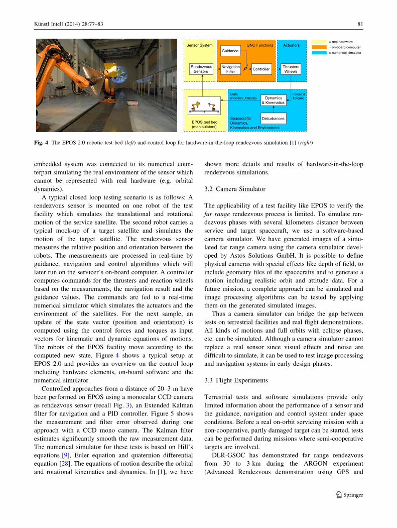
computed new state. Figure 4 shows a typical setup at
EPOS 2.0 and provides an overview on the control loop
including hardware elements, on-board software and the
numerical simulator.
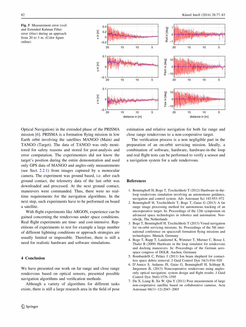
Controlled approaches from a distance of 20–3 m have
been performed on EPOS using a monocular CCD camera
as rendezvous sensor (recall Fig. 3), an Extended Kalman
filter for navigation and a PID controller. Figure 5 shows
the measurement and filter error observed during one
approach with a CCD mono camera. The Kalman filter
estimates significantly smooth the raw measurement data.
The numerical simulator for these tests is based on Hill’s
equations [9], Euler equation and quaternion differential
equation [28]. The equations of motion describe the orbital
and rotational kinematics and dynamics. In [1], we have
shown more details and results of hardware-in-the-loop
rendezvous simulations.
3.2 Camera Simulator
The applicability of a test facility like EPOS to verify the
far range rendezvous process is limited. To simulate ren-
dezvous phases with several kilometers distance between
service and target spacecraft, we use a software-based
camera simulator. We have generated images of a simu-
lated far range camera using the camera simulator devel-
oped by Astos Solutions GmbH. It is possible to define
physical cameras with special effects like depth of field, to
include geometry files of the spacecrafts and to generate a
motion including realistic orbit and attitude data. For a
future mission, a complete approach can be simulated and
image processing algorithms can be tested by applying
them on the generated simulated images.
Thus a camera simulator can bridge the gap between
tests on terrestrial facilities and real flight demonstrations.
All kinds of motions and full orbits with eclipse phases,
etc. can be simulated. Although a camera simulator cannot
replace a real sensor since visual effects and noise are
difficult to simulate, it can be used to test image processing
and navigation systems in early design phases.
3.3 Flight Experiments
Terrestrial tests and software simulations provide only
limited information about the performance of a sensor and
the guidance, navigation and control system under space
conditions. Before a real on-orbit servicing mission with a
non-cooperative, partly damaged target can be started, tests
can be performed during missions where semi-cooperative
targets are involved.
DLR-GSOC has demonstrated far range rendezvous
from 30 to 3 km during the ARGON experiment
(Advanced Rendezvous demonstration using GPS and
Controller
Guidance
NavigationFilter
+
-
GNC Functions
ThrustersWheels
Actuators
Dynamics& Kinematics
Disturbances
Forces & Torques
RendezvousSensors
State (Position, Attitude)
Sensor System
Spacecrafts’Dynamics, Kinematics and Environment
= real hardware
= numerical simulator
= on-board computer
EPOS test bed(manipulators)
Fig. 4 The EPOS 2.0 robotic test bed (left) and control loop for hardware-in-the-loop rendezvous simulation [1] (right)
Kunstl Intell (2014) 28:77–83 81
123
Optical Navigation) in the extended phase of the PRISMA
mission [6]. PRISMA is a formation flying mission in low
Earth orbit involving the satellites MANGO (Main) and
TANGO (Target). The data of TANGO was only moni-
tored for safety reasons and stored for post-analysis and
error computation. The experimenters did not know the
target’s position during the entire demonstration and used
only GPS data of MANGO and angles-only measurements
(see Sect. 2.2.1) from images captured by a monocular
camera. The experiment was ground based, i.e. after each
ground contact, the telemetry data of the last orbit was
downloaded and processed. At the next ground contact,
maneuvers were commanded. Thus, there were no real-
time requirements for the navigation algorithms. In the
next step, such experiments have to be performed on board
a satellite.
With flight experiments like ARGON, experience can be
gained concerning the rendezvous under space conditions.
Real flight experiments are time- and cost-intensive. Rep-
etitions of experiments to test for example a large number
of different lightning conditions or approach strategies are
usually limited or impossible. Therefore, there is still a
need for realistic hardware and software simulations.
4 Conclusion
We have presented our work on far range and close range
rendezvous based on optical sensors, presented possible
navigation algorithms and verification methods.
Although a variety of algorithms for different tasks
exists, there is still a large research area in the field of pose
estimation and relative navigation for both far range and
close range rendezvous to a non-cooperative target.
The verification process is a non negligible part in the
preparation of an on-orbit servicing mission. Ideally, a
combination of software, hardware, hardware-in-the loop
and real flight tests can be performed to verify a sensor and
a navigation system for a safe rendezvous.
References
1. Benninghoff H, Boge T, Tzschichholz T (2012) Hardware-in-the-
loop rendezvous simulation involving an autonomous guidance,
navigation and control system. Adv Astronaut Sci 145:953–972
2. Benninghoff H, Tzschichholz T, Boge T, Gaias G (2013) A far
range image processing method for autonomous tracking of an
uncooperative target. In: Proceedings of the 12th symposium on
advanced space technologies in robotics and automation. Noo-
rdwijk, The Netherlands
3. Boge T, Benninghoff H, Tzschichholz T (2013) Visual navigation
for on-orbit servicing missions. In: Proceedings of the 5th inter-
national conference on spacecraft formation flying missions and
technologies. Munich, Germany
4. Boge T, Rupp T, Landzettel K, Wimmer T, Mietner C, Bosse J,
Thaler B (2009) Hardware in the loop simulator for rendezvous
and docking maneuvers. In: Proceedings of the German aero-
space congress of DGLR. Aachen, Germany
5. Bombardelli C, Pelaez J (2011) Ion beam shepherd for contact-
less space debris removal. J Guid Control Dyn 34(3):916–920
6. D’Amico S, Ardaens JS, Gaias G, Benninghoff H, Schlepp B,
Jørgensen JL (2013) Noncooperative rendezvous using angles-
only optical navigation: system design and flight results. J Guid
Control Dyn 36(6):1576–1595
7. Du X, Liang B, Xu W, Qiu Y (2011) Pose measurement of large
non-cooperative satellite based on collaborative cameras. Acta
Astronaut 68(11–12):2047–2065
5101520
−0.2
0
0.2
0.4
x in
[m]
5101520−0.1
0
0.1
y in
[m]
5101520−0.1
0
0.1
z in
[m]
distance in [m]
5101520
−1
0
1
Rol
l in
[deg
]
5101520
−10
0
10
Pitc
h in
[deg
]
5101520
−10
0
10
Yaw
in [d
eg]
distance in [m]
Fig. 5 Measurement error (red)
and Extended Kalman Filter
error (blue) during an approach
from 20 to 3 m. (Color figure
online)
82 Kunstl Intell (2014) 28:77–83
123
8. Ellery A, Kreisel J, Sommer B (2008) The case for robotic on-
orbit servicing of spacecraft: spacecraft reliability is a myth. Acta
Astronaut 63(5–6):632–648
9. Fehse W (2003) Automated rendezvous and docking of space-
craft. Cambridge Aerospace Series, Washington, DC
10. Jasiobedzki P, Se S, Pan T, Umasuthan M, Greenspan M (2005)
Autonomous satellite rendezvous and docking using LIDAR and
model based vision. In: Proceedings of the SPIE 5798, Space-
borne Sensors II, vol 54
11. Jørgensen JL, Benn M (2010) VBS–the optical rendezvous and
docking sensor for PRISMA. Nordic Space
12. Julier S, Uhlmann J (1995) A new approach for filtering nonlinear
systems. In: Proceedings of 1995 American control conference,
vol 3
13. Julier S, Uhlmann J (1997) A new extension of the kalman filter
to nonlinear systems. In: Proceedings of AeroSence: the 11th
international symposium on aerospace/defense sensing, simula-
tions and controls, vol 3
14. Kaiser C, Sjoberg F, Delcura JM, Eilertsen B (2008) SMART-
OLEV–an orbital life extension vehicle for servicing commercial
spacecrafts in GEO. Acta Astronaut 63(1–4):400–410
15. Kalman RE (1960) A new approach to linear filtering and pre-
diction problems. Trans ASME J Basic Eng 83:35–45
16. Levenberg K (1944) A method for the solution of certain prob-
lems in least squares. Q Appl Math 2:164–168
17. Marquardt D (1963) An algorithm for least-squares estimation of
nonlinear parameters. SIAM J Appl Math 11:431–441
18. Muhlbauer Q, Rank P, Kaiser C (2013) On-ground verification of
VIBANASS (vision based navigation sensor system): capabilities
and results. In: Proceedings of the 12th symposium on advanced
space technologies in robotics and automation. Noordwijk, The
Netherlands
19. Nishida SI, Kawamoto S, Okawa Y, Terui F, Kitamura S (2009)
Space debris removal system using a small satellite. Acta
Astronaut 65(1–2):95–102
20. Oumer NW, Panin G (2012) Tracking and pose estimation of a
non-cooperative satellite using stereo images for on-orbit ser-
vicing. In: Proceedings of the international symposium on arti-
ficial intelligence, robotics and automation in space (i-SAIRAS).
European Space Agency, Turin, Italy
21. Qiao B, Tang S, Ma K, Liu Z (2013) Relative pose and attitude
estimation of spacecrafts based on dual quaternion for rendezvous
and docking. Acta Astronaut 91:237–244
22. Qureshi F, Terzopoulos D (2008) Intelligent perception and
control for space robotics: autonomous satellite rendezvous and
docking. Mach Vis Appl 19(3):141–161
23. Shahid K, Okouneva G (2007) Intelligent LIDAR scanning
region selection for satellite pose estimation. Comput Vis Image
Underst 107(3):203–209
24. Sommer J, Ahrns I (2013) GNC for rendezvous in space with an
uncooperative target. In: Proceedings of the 5th international
conference on spacecraft formation flying missions and technol-
ogies. Munich, Germany
25. Stoll E, Letschnik J, Walter U, Artigas J, Kremer P, Preusche C,
Hirzinger G (2009) On-orbit servicing. Robot Autom Mag IEEE
16(4):29–33
26. Tzschichholz T, Boge T, Benninghoff H (2011) A flexible image
processing framework for vision-based navigation using monoc-
ular imaging sensors. In: Proceedings of the 8th international
ESA conference on guidance, navigation & control systems.
Karlovy Vary, Czech Republic
27. Tzschichholz T, Ma L, Schilling K (2011) Model-based space-
craft pose estimation and motion prediction using a photonic
mixer device camera. Acta Astronaut 68(7–8):1156–1167
28. Wertz JR (2002) Attitude determination and control. Kluwer,
Dordrecht
29. Woffinden DC, Geller DK (2007) Relative angles-only naviga-
tion and pose estimation for autonomous orbital rendezvous.
J Guid Control Dyn 30:1455–1469
30. Xu W, Liang B, Li C, Xu Y (2010) Autonomous rendezvous and
robotic capturing of non-cooperative target in space. Robotica
28(5):705–718
31. Yasaka T, Ashford EW (1996) GSV: an approach toward space
system servicing. Earth Space Rev 5(2):9–17
32. Zarchan P, Musoff H (2000) Fundamentals of Kalman filtering: a
practical approach, vol 190. Progress in Astronautics and Aero-
nautics, Cambridge, MA
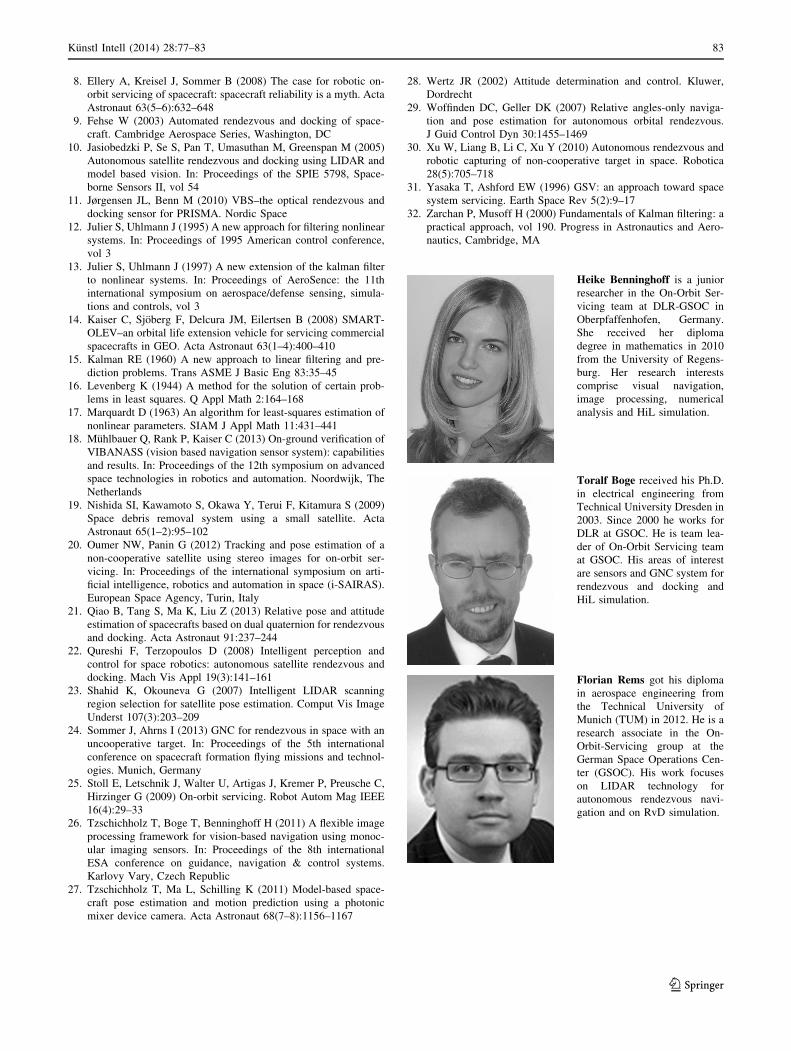
Heike Benninghoff is a junior
researcher in the On-Orbit Ser-
vicing team at DLR-GSOC in
Oberpfaffenhofen, Germany.
She received her diploma
degree in mathematics in 2010
from the University of Regens-
burg. Her research interests
comprise visual navigation,
image processing, numerical
analysis and HiL simulation.
Toralf Boge received his Ph.D.
in electrical engineering from
Technical University Dresden in
2003. Since 2000 he works for
DLR at GSOC. He is team lea-
der of On-Orbit Servicing team
at GSOC. His areas of interest
are sensors and GNC system for
rendezvous and docking and
HiL simulation.
Florian Rems got his diploma
in aerospace engineering from
the Technical University of
Munich (TUM) in 2012. He is a
research associate in the On-
Orbit-Servicing group at the
German Space Operations Cen-
ter (GSOC). His work focuses
on LIDAR technology for
autonomous rendezvous navi-
gation and on RvD simulation.
Kunstl Intell (2014) 28:77–83 83
123
![Autonomous Satellite Servicing Using the Orbital Express ...robotics.estec.esa.int/i-SAIRAS/isairas2008... · Demonstration System [1] was to demonstrate the operational utility and](https://img.pdfslide.net/doc/110x75/5f2889cd3a80a7140266488d/autonomous-satellite-servicing-using-the-orbital-express-demonstration-system.jpg)


![Orbit type: Sun Synchronous Orbit ] Orbit height: …...Orbit type: Sun Synchronous Orbit ] PSLV - C37 Orbit height: 505km Orbit inclination: 97.46 degree Orbit period: 94.72 min ISL](https://img.pdfslide.net/doc/110x75/5f781053e671b364921403bc/orbit-type-sun-synchronous-orbit-orbit-height-orbit-type-sun-synchronous.jpg)


![Solid Propellant Autonomous DE-Orbit System [SPADES]](https://img.pdfslide.net/doc/110x75/620280c02fda4a4c6d4aa41e/solid-propellant-autonomous-de-orbit-system-spades.jpg)