Embed Size (px)
Citation preview
Autonomous Quadrocopter ProposalBrad Bergerhouse, Nelson Gaske, Austin WenzelDr. Malinowski
2
Outline Introduction Goals Project Description Tests Schedule
3
Outline Introduction Goals Project Description Tests Schedule
4
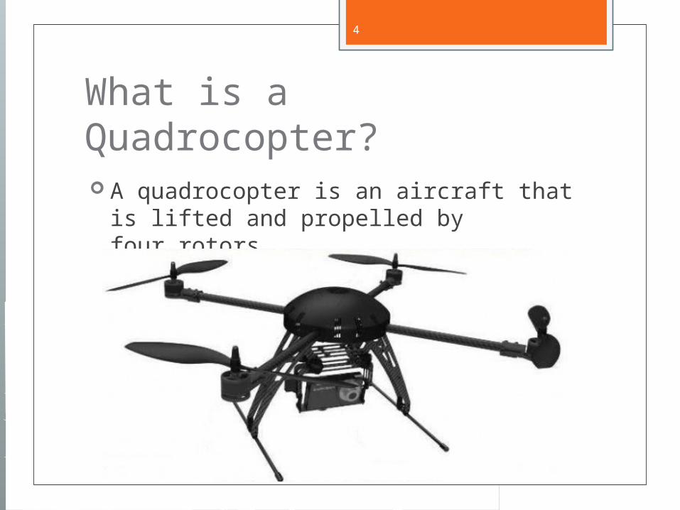
What is a Quadrocopter? A quadrocopter is an aircraft that is
lifted and propelled by four rotors.
5
Why is this technology important? Quadrocopters are inherently stable
platforms which share advantages with helicopters and airplanes, without the disadvantages
Microprocessor and DSP chip integration provides an powerful core while maintaining the low power usage of single chip processors

6
Why this project? To develop an autonomous vehicle with
6-DOF Tackle challenges presented during 3
dimensional navigation with minimal sensors
Provides a unique opportunity to implement an aerial platform for use in future department projects and courses
7
Outline Introduction Goals Project Description Tests Schedule
8
Goals Implement backup fly-by-wire controls
for safety and testing Avoid obstacles using video and sensor
feedback Autonomously navigate through narrow
passages using onboard sensors Develop a quadrocopter platform for
future senior projects
9
Fly-by-wire Remotely control quadrocopter with
computer joystick or R/C transmitter for safety
Implemented to prevent loss of control during development and testing
10
Obstacle Avoidance Use range sensors and single camera to
avoid obstacles Range sensors will be (initially)
positioned in all 6 Euclidian directions Camera will be aimed forward and DSP
will be used for object detection
11
Autonomous Navigation Navigate narrow passages in a fully
autonomous nature Create ‘obstacles’ using symbols to
indicate directional constraints
12
Future Platform Fully document design process and
component interfacing Expandable processing and I/O
components
13
Outline Introduction Goals Project Description Tests Schedule
14
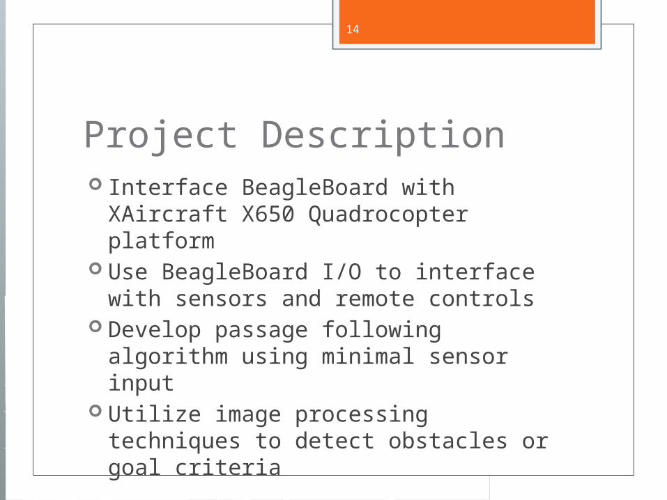
Project Description Interface BeagleBoard with XAircraft
X650 Quadrocopter platform Use BeagleBoard I/O to interface with
sensors and remote controls Develop passage following algorithm
using minimal sensor input Utilize image processing techniques to
detect obstacles or goal criteria

15
System Diagram
XAircraft X650
BeagleBoard
IR Distance SensorsSharp GP2Y0A02YK0F
Octal ADC TI ADS7823-28EVM
5MP CameraLI-LBCM5M1
WifiAccelerometer
I2C
Serial
Laptop
RC Controller
DSP
DM3730CBP Processor
USB
Flight Control Board
Motor ESC’s
PWMUltraPWM
Motors
16
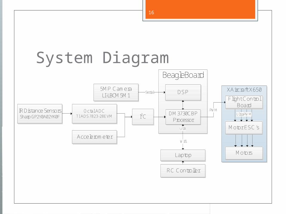
System Diagram
XAircraft X650
BeagleBoard
IR Distance SensorsSharp GP2Y0A02YK0F
Octal ADC TI ADS7823-28EVM
5MP CameraLI-LBCM5M1
WifiAccelerometer
I2C
Serial
Laptop
RC Controller
DSP
DM3730CBP Processor
USB
Flight Control Board
Motor ESC’s
PWMUltraPWM
Motors
17
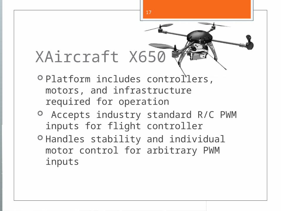
XAircraft X650 Platform includes controllers, motors,
and infrastructure required for operation Accepts industry standard R/C PWM
inputs for flight controller Handles stability and individual motor
control for arbitrary PWM inputs

18
System Diagram
XAircraft X650
BeagleBoard
IR Distance SensorsSharp GP2Y0A02YK0F
Octal ADC TI ADS7823-28EVM
5MP CameraLI-LBCM5M1
WifiAccelerometer
I2C
Serial
Laptop
RC Controller
DSP
DM3730CBP Processor
USB
Flight Control Board
Motor ESC’s
PWMUltraPWM
Motors
19
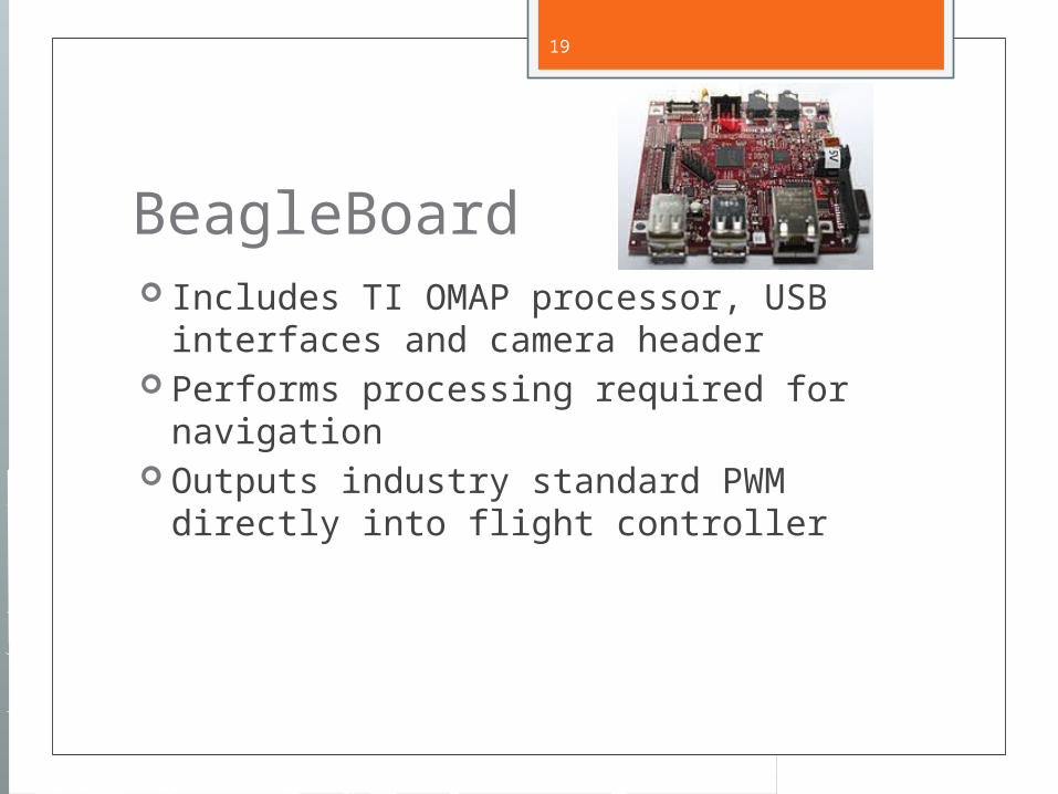
BeagleBoard Includes TI OMAP processor, USB
interfaces and camera header Performs processing required for
navigation Outputs industry standard PWM directly
into flight controller
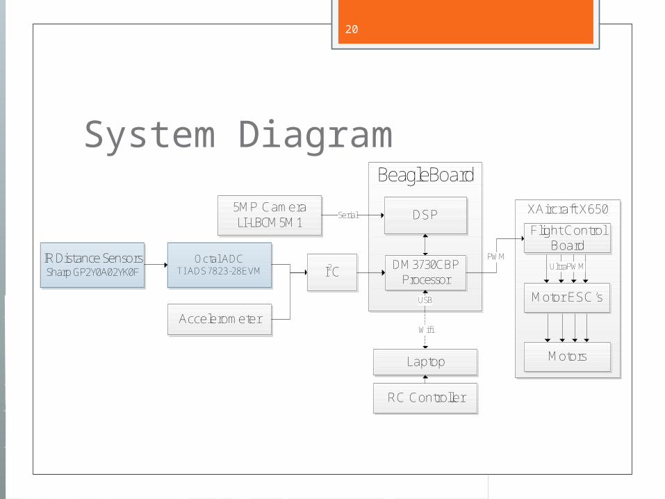
20
System Diagram
XAircraft X650
BeagleBoard
IR Distance SensorsSharp GP2Y0A02YK0F
Octal ADC TI ADS7823-28EVM
5MP CameraLI-LBCM5M1
WifiAccelerometer
I2C
Serial
Laptop
RC Controller
DSP
DM3730CBP Processor
USB
Flight Control Board
Motor ESC’s
PWMUltraPWM
Motors
21
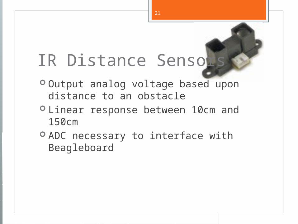
IR Distance Sensors Output analog voltage based upon
distance to an obstacle Linear response between 10cm and
150cm ADC necessary to interface with
Beagleboard
22
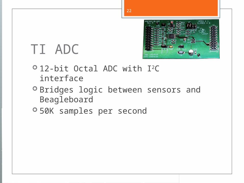
TI ADC 12-bit Octal ADC with I2C interface Bridges logic between sensors and
Beagleboard 50K samples per second
23
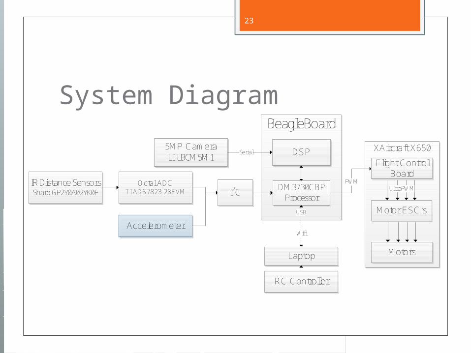
System Diagram
XAircraft X650
BeagleBoard
IR Distance SensorsSharp GP2Y0A02YK0F
Octal ADC TI ADS7823-28EVM
5MP CameraLI-LBCM5M1
WifiAccelerometer
I2C
Serial
Laptop
RC Controller
DSP
DM3730CBP Processor
USB
Flight Control Board
Motor ESC’s
PWMUltraPWM
Motors
24
Accelerometer Possibly used for orientation input to
BeagleBoard

25
System Diagram
XAircraft X650
BeagleBoard
IR Distance SensorsSharp GP2Y0A02YK0F
Octal ADC TI ADS7823-28EVM
5MP CameraLI-LBCM5M1
WifiAccelerometer
I2C
Serial
Laptop
RC Controller
DSP
DM3730CBP Processor
USB
Flight Control Board
Motor ESC’s
PWMUltraPWM
Motors
26
I2C Interface Inter-Integrated Circuit Master-slave 2-wire bus interface Used to communicate between ADC,
Accelerometer, and BeagleBoard Additional logic level converter required
to interface between BeagleBoard (1.8V) and ADC (5V)
27
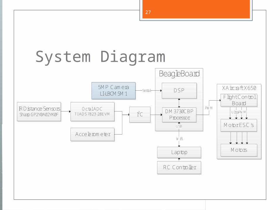
System Diagram
XAircraft X650
BeagleBoard
IR Distance SensorsSharp GP2Y0A02YK0F
Octal ADC TI ADS7823-28EVM
5MP CameraLI-LBCM5M1
WifiAccelerometer
I2C
Serial
Laptop
RC Controller
DSP
DM3730CBP Processor
USB
Flight Control Board
Motor ESC’s
PWMUltraPWM
Motors
28
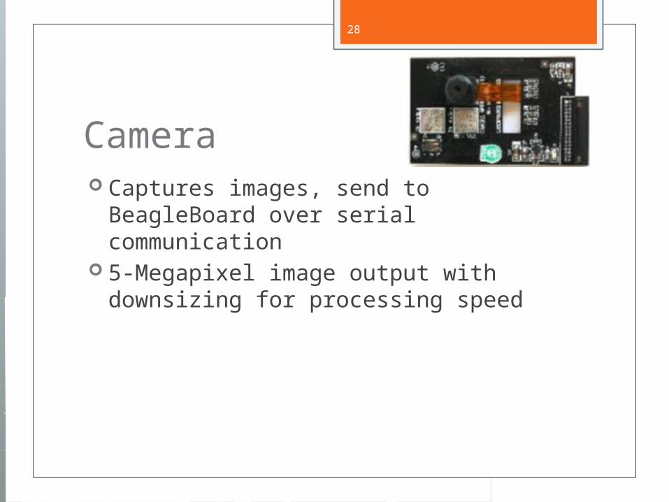
Camera Captures images, send to BeagleBoard
over serial communication 5-Megapixel image output with
downsizing for processing speed
29
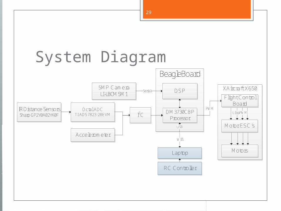
System Diagram
XAircraft X650
BeagleBoard
IR Distance SensorsSharp GP2Y0A02YK0F
Octal ADC TI ADS7823-28EVM
5MP CameraLI-LBCM5M1
WifiAccelerometer
I2C
Serial
Laptop
RC Controller
DSP
DM3730CBP Processor
USB
Flight Control Board
Motor ESC’s
PWMUltraPWM
Motors
30
Laptop Communicates via 802.11 wireless
protocol to BeagleBoard Transmits manual override controls to
Beagleboard Provides goal conditions for navigation Can act as a data store for retrieved
information
31
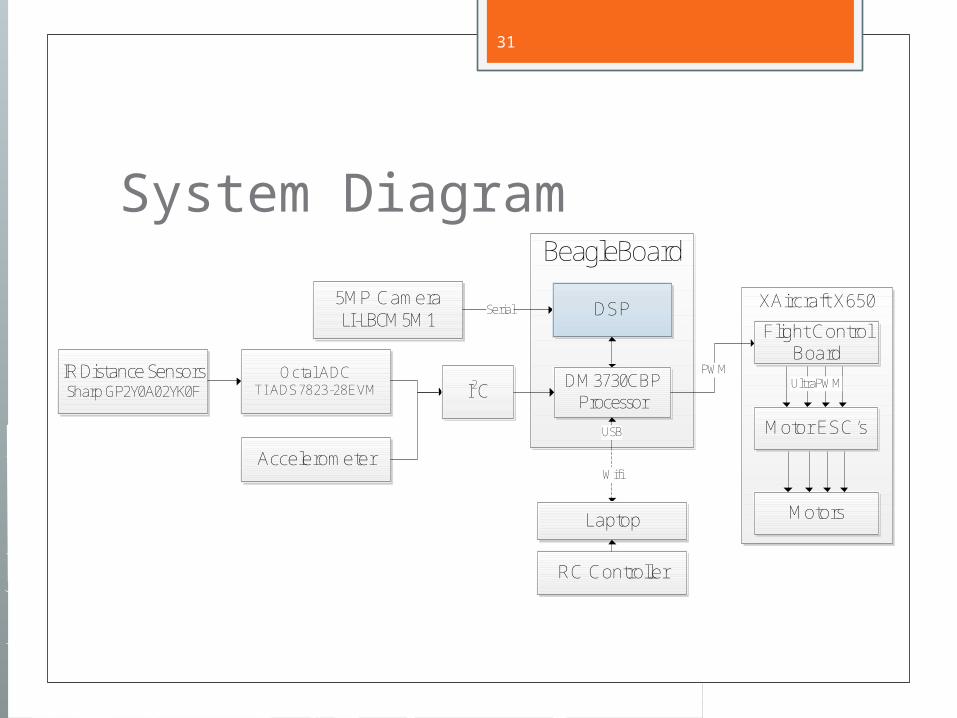
System Diagram
XAircraft X650
BeagleBoard
IR Distance SensorsSharp GP2Y0A02YK0F
Octal ADC TI ADS7823-28EVM
5MP CameraLI-LBCM5M1
WifiAccelerometer
I2C
Serial
Laptop
RC Controller
DSP
DM3730CBP Processor
USB
Flight Control Board
Motor ESC’s
PWMUltraPWM
Motors
32
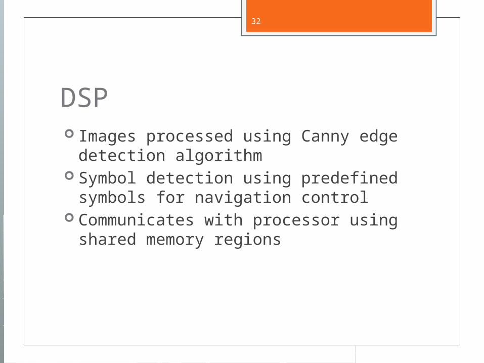
DSP Images processed using Canny edge
detection algorithm Symbol detection using predefined
symbols for navigation control Communicates with processor using
shared memory regions
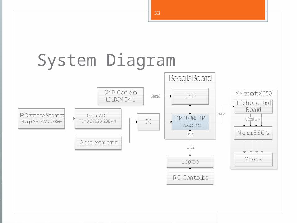
33
System Diagram
XAircraft X650
BeagleBoard
IR Distance SensorsSharp GP2Y0A02YK0F
Octal ADC TI ADS7823-28EVM
5MP CameraLI-LBCM5M1
WifiAccelerometer
I2C
Serial
Laptop
RC Controller
DSP
DM3730CBP Processor
USB
Flight Control Board
Motor ESC’s
PWMUltraPWM
Motors
34
OMAP ARM core Interprets sensor information Provides control outputs to platform Monitors sensor inputs for proper goal
conditions
35
Outline Introduction Goals Project Description Tests Schedule
36
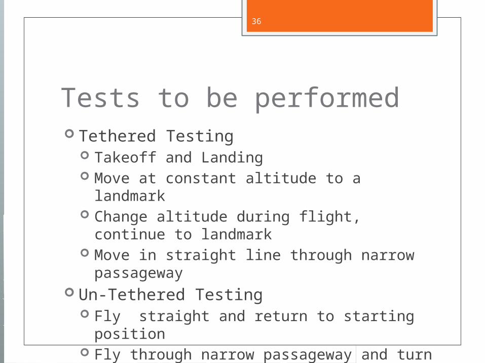
Tests to be performed Tethered Testing
Takeoff and Landing Move at constant altitude to a landmark Change altitude during flight, continue to
landmark Move in straight line through narrow
passageway Un-Tethered Testing
Fly straight and return to starting position Fly through narrow passageway and turn
corner
37
Outline Introduction Goals Project Description Tests Schedule

38
Division of labor Austin
DSP and object recognition Brad
Communication and networking Nelson
Hardware interfacing and power management
39
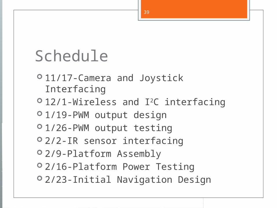
Schedule 11/17-Camera and Joystick Interfacing 12/1-Wireless and I2C interfacing 1/19-PWM output design 1/26-PWM output testing 2/2-IR sensor interfacing 2/9-Platform Assembly 2/16-Platform Power Testing 2/23-Initial Navigation Design
40
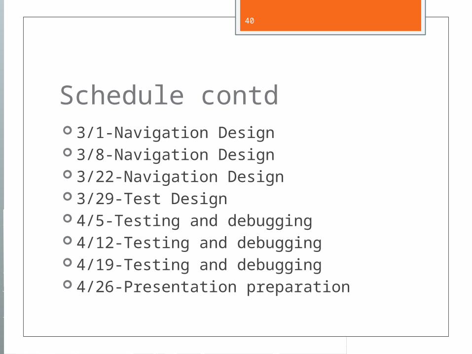
Schedule contd 3/1-Navigation Design 3/8-Navigation Design 3/22-Navigation Design 3/29-Test Design 4/5-Testing and debugging 4/12-Testing and debugging 4/19-Testing and debugging 4/26-Presentation preparation
41
Questions?