Embed Size (px)
Citation preview
AutoScan version 2: optical and magneto-optical
measurement system
Manual Revision 1.1
Designed and built by: Dr. Gregory S. Jenkins University of Maryland at College Park Department of Physics John S. Toll Physics building, 2nd floor [email protected] Office: 301-405-0076 Cell: 301-793-2055 website Manual last updated on 11/21/2017
Introduction Optical measurements in our laboratory integrate lasers and spectrometers with cryogenically cooled detectors, cryostats, and a superconducting magnet. These measurements are generally time intensive. Cryogen management is a large component. Minimizing noise and optimizing optical stability takes a substantial amount of time. Attaining complete data sets is a long and repetitive process interspersed by the need to change settings, hardware, or optical components. Hardware failures or extrinsic electrical or vibrational induced noise are additional intermittent problems requiring user intervention. The recent implementation of an automatic laboratory helium recovery system minimizes time committed to cryogen management and opened the prospect of unattended data acquisition. Without the benefits of a helium recovery system, helium losses from derailed experiments during unattended data acquisition would be prohibitively large. No such penalty exists with a helium recovery system, and an immense amount of time may be leveraged by a single user. Unattended data acquisition alleviates fatigue associated with blocks of consecutive days, or even weeks, of long hours taking data. Such fatigue leads to truncating the data acquisition process to alleviate physical and mental pain at the expense of complete data sets, better signal averaging, or remeasuring problematic data. Automation of laboratory experiments is not novel. However, the scope and certain aspects of this project are notable: (1) control of a Bomem DA8 FTIR spectrometer (with antiquated hardware and software) and automatic conversion of SPC/IGM/IGN file types (2) protect an old Oxford superconducting magnet system, by implementing custom hardware and software interlocks, from unattended power outages, low helium levels, and quenches, (3) actuate a Janis cryostat by retrofitting a closed-loop stepper motor and gear system with safety limiting and homing switches, fail-safes from power outages, and electrical isolation from sensitive equipment from (noisy) motor pulses, (4) enable a full range of sample temperatures with minimal heater power for two continuous flow cryostats by designing and fabricating an automated throttling helium exhaust manifold, (5) incorporate a flexible control program with a scripting language that easily accommodates new hardware components and adapts to variability in experimental arrangements and procedures. The main barriers preventing implementation of full automation are the overhead time associated with designing, programming, fabricating, and testing the automatic system as well as safely mitigating all potential problems with a combination of hardware and software interlocks. I began implementing the automatic system while attaining large data sets. As the automation began saving time, I used the extra time to implement further automation. The time savings was so large that within a three-month period beginning in July 2017, working the equivalent of about one month full-time on the automation project, the system was fully implemented. The versatility and adaptability of the program allows for easy expansion to include other hardware.
Overview A Labview program currently controls the Bomem DA8 FTIR spectrometer, an Oxford magnet controller and ILM Helium level gauge, two Lakeshore temperature controllers, a helium exhaust manifold assembly with four solenoid valves, a polarizer or waveplate rotation stage, and a closed-loop stepper motor that translates between two samples in a Janis cryostat. Experiments that are currently automated are various configurations of laser and spectroscopic optical and magneto-optical measurements. The program is designed to be easily extended to other devices. Multiple layers of hardware and software interlocks are implemented for user safety and equipment protection.
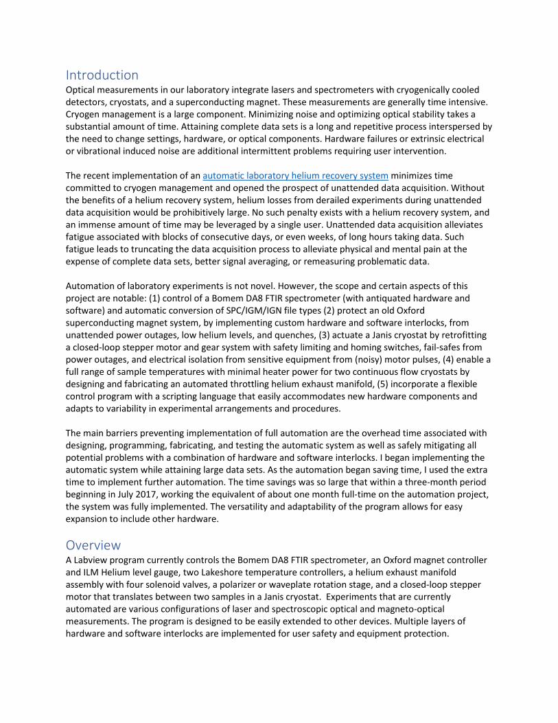
Bomem DA8 control The Bomem DA8 is controlled by proprietary software, called the “PCDA” program. Fortunately, ABB Bomem implemented a dynamic data exchange (DDE) protocol. This protocol is native to Windows, and was popular in the 1990’s. It allows programs to communicate with each other. The PCDA software runs on Windows XP or prior Windows operating systems, and the computer hardware must support an old ISA bus plug-in card to communicate with the DA8 on-board computer. Such old hardware is far from ideal as a base platform to implement extensive laboratory automation. To circumvent this limitation, a small program with minimum CPU and memory overhead was developed in Labview that runs on WindowsXP. This software, shown in Figure 1, is a bridge linking TCP/IP communication with the PCDA via DDE. It establishes a link that accepts commands sent from another computer using TCP/IP over standard ethernet. It also establishes a DDE link to the PCDA software, and routes these received commands to the PCDA program. Responses from the PCDA program are routed back to the controlling computer over TCP/IP. The software utilizes standard buffering
techniques. The DDE commands implemented by the PCDA DA8 software are extensive. Every aspect of the spectrometer is controlled through the Labview bridge software from the main automation control computer. A complete DDE command summary can be found in the PCDA documentation.
Janis Cryostat An Arcus model DMX-Eth-23 was used in conjunction with an MDC bellows actuator and bracket with a worm gear system. The motor is an integrated ethernet stepper motor, meaning that the motor controller and the optical encoder in addition to the feedback circuit is attached directly to the motor housing. This motor was chosen to forego long radiating wires carrying pulses to the motor windings as well as its superb built-in optical encoding feedback allowing closed-loop operation, an essential requirement for unattended optical measurements. The motor and housing are electrically isolated from the cryostat and spectrometer by using plastic screws and kapton tape that isolate the brass worm gear from the MDC actuator, and kapton tape underneath the bracket that clamps the motor to the cryostat. The electrical isolation minimizes radiative pick-up and ground-pulse noise from the spectrometer and attached detectors.
Figure 1: Bomem DA8 Labview bridge program buffers DDE commands and responses to and from the PCDA software and passes them to the client Labview program over TCP/IP.
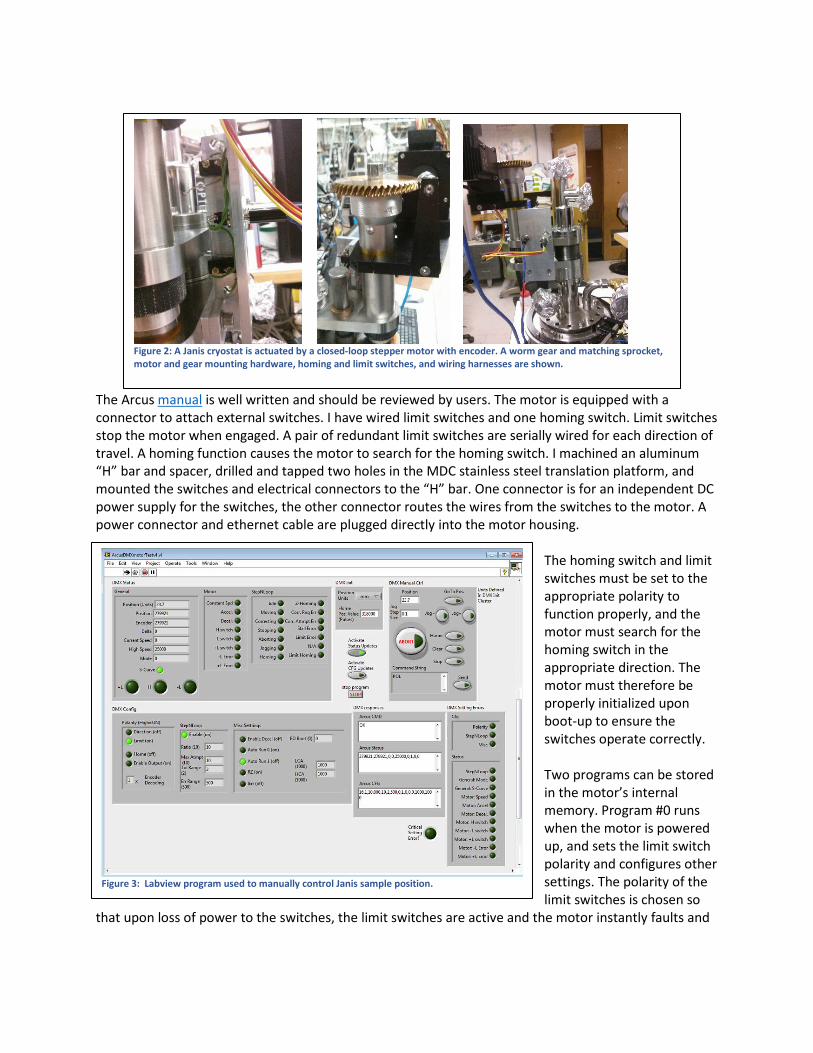
The Arcus manual is well written and should be reviewed by users. The motor is equipped with a connector to attach external switches. I have wired limit switches and one homing switch. Limit switches stop the motor when engaged. A pair of redundant limit switches are serially wired for each direction of travel. A homing function causes the motor to search for the homing switch. I machined an aluminum “H” bar and spacer, drilled and tapped two holes in the MDC stainless steel translation platform, and mounted the switches and electrical connectors to the “H” bar. One connector is for an independent DC power supply for the switches, the other connector routes the wires from the switches to the motor. A power connector and ethernet cable are plugged directly into the motor housing.
The homing switch and limit switches must be set to the appropriate polarity to function properly, and the motor must search for the homing switch in the appropriate direction. The motor must therefore be properly initialized upon boot-up to ensure the switches operate correctly. Two programs can be stored in the motor’s internal memory. Program #0 runs when the motor is powered up, and sets the limit switch polarity and configures other settings. The polarity of the limit switches is chosen so
that upon loss of power to the switches, the limit switches are active and the motor instantly faults and
Figure 2: A Janis cryostat is actuated by a closed-loop stepper motor with encoder. A worm gear and matching sprocket, motor and gear mounting hardware, homing and limit switches, and wiring harnesses are shown.
Figure 3: Labview program used to manually control Janis sample position.
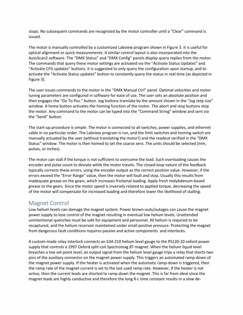
stops. No subsequent commands are recognized by the motor controller until a “Clear” command is issued. The motor is manually controlled by a customized Labview program shown in Figure 3. It is useful for optical alignment or quick measurements. A similar control layout is also incorporated into the AutoScan2 software. The “DMX Status” and “DMX Config” panels display query replies from the motor. The commands that query these motor settings are activated via the “Activate Status Updates” and “Activate CFG updates” buttons. It is suggested to only query the configuration upon startup, and to activate the “Activate Status updates” button to constantly query the status in real time (as depicted in Figure 3). The user issues commands to the motor in the “DMX Manual Ctrl” panel. Optimal velocities and motor tuning parameters are configured in software for ease of use. The user sets an absolute position and then engages the “Go To Pos.” button. Jog buttons translate by the amount shown in the “Jog step size” window. A home button activates the homing function of the motor. The abort and stop buttons stop the motor. Any command to the motor can be typed into the “Command String” window and sent via the “Send” button. The start-up procedure is simple. The motor is connected to all switches, power supplies, and ethernet cable in no particular order. The Labview program is run, and the limit switches and homing switch are manually actuated by the user (without translating the motor!) and the readout verified in the “DMX Status” window. The motor is then homed to set the coarse zero. The units should be selected (mm, pulses, or inches). The motor can stall if the torque is not sufficient to overcome the load. Such overloading causes the encoder and pulse count to deviate while the motor travels. The closed-loop nature of the feedback typically corrects these errors, using the encoder output as the correct position value. However, if the errors exceed the “Error Range” value, then the motor will fault and stop. Usually this results from inadequate grease on the gears, which increases frictional loading. Apply fresh molybdenum-based grease to the gears. Since the motor speed is inversely related to applied torque, decreasing the speed of the motor will compensate for increased loading and therefore lower the likelihood of stalling.
Magnet Control Low helium levels can damage the magnet system. Power brown-outs/outages can cause the magnet power supply to lose control of the magnet resulting in eventual low helium levels. Unattended unintentional quenches must be safe for equipment and personnel. All helium is required to be recaptured, and the helium reservoir maintained under small positive pressure. Protecting the magnet from dangerous fault conditions requires passive and active components and interlocks. A custom-made relay interlock connects an ILM-210 helium level gauge to the PS120-10 oxford power supply that controls a 1997 Oxford split-coil Spectromag 8T magnet. When the helium liquid level breaches a low set-point level, an output signal from the helium level gauge trips a relay that shorts two pins of the auxiliary connector on the magnet power supply. This triggers an automated ramp-down of the magnet power supply. If the heater is activated when the automatic ramp-down is triggered, then the ramp rate of the magnet current is set to the last used ramp rate. However, if the heater is not active, then the current leads are shorted to ramp down the magnet. This is far from ideal since the magnet leads are highly conductive and therefore the long R-L time constant results in a slow de-
energizing ramp rate. Note that high power diodes with high current relays could be implemented to increase the ramp rate under this condition, but this has not yet been implemented. For extra protection, a UPS has been implemented to allow the system to run for up to 40 minutes during power outages. This allows the main Labview control computer running ASv2 (with its own UPS) to automatically ramp down the magnet in a more controlled way. Software interlocks will be discussed later. The magnet helium reservoir must be kept near atmosphere (above atmosphere pressure raises the temperature) but at slight over-pressure to ensure that no air or water is cryo-pumped into the reservoir. The connection of the magnet helium reservoir to the helium bladder must have an in-line check valve. However, the valve impedes helium gas flow during a quench potentially causing excessive pressure in the magnet helium reservoir. Also, an in-line check valve makes it difficult to pump and purge the magnet reservoir when preparing the magnet for a liquid helium transfer. To solve these problems, an in-line check valve is inserted into the system at the main laboratory manifold (see the helium recovery system manual) after filling the magnet with liquid helium. This large Cv check valve manufactured by Generant, equipped with KF-40 flanges, is swapped with a pipe section of similar dimensions, and maintains the magnet reservoir at around 0.2 PSIG during normal running conditions. Three quenches have occurred through this valve with only 3-4PSIG pressure rise in the helium reservoir while permitting complete re-capture of helium exhaust gas. A pop-off relief valve is located on the magnet reservoir that prevents catastrophic over-pressurization of the reservoir.
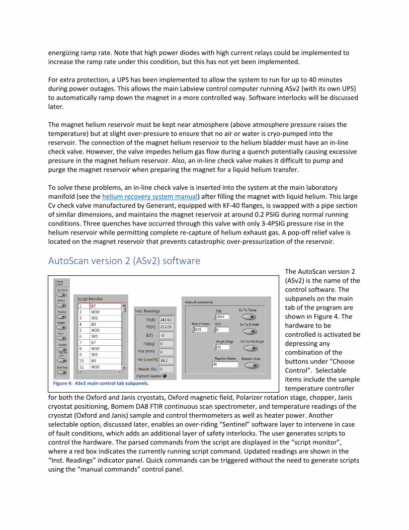
AutoScan version 2 (ASv2) software The AutoScan version 2 (ASv2) is the name of the control software. The subpanels on the main tab of the program are shown in Figure 4. The hardware to be controlled is activated be depressing any combination of the buttons under “Choose Control”. Selectable items include the sample temperature controller
for both the Oxford and Janis cryostats, Oxford magnetic field, Polarizer rotation stage, chopper, Janis cryostat positioning, Bomem DA8 FTIR continuous scan spectrometer, and temperature readings of the cryostat (Oxford and Janis) sample and control thermometers as well as heater power. Another selectable option, discussed later, enables an over-riding “Sentinel” software layer to intervene in case of fault conditions, which adds an additional layer of safety interlocks. The user generates scripts to control the hardware. The parsed commands from the script are displayed in the “script monitor”, where a red box indicates the currently running script command. Updated readings are shown in the “Inst. Readings” indicator panel. Quick commands can be triggered without the need to generate scripts using the “manual commands” control panel.
Figure 4: ASv2 main control tab subpanels.
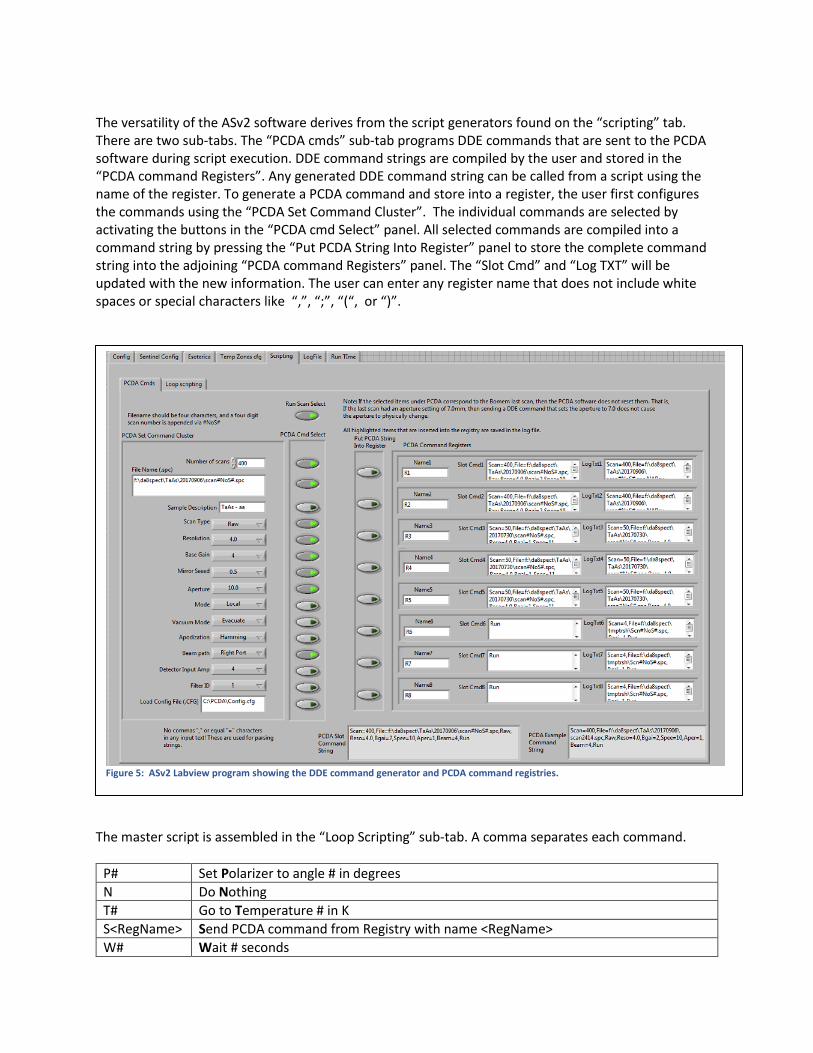
The versatility of the ASv2 software derives from the script generators found on the “scripting” tab. There are two sub-tabs. The “PCDA cmds” sub-tab programs DDE commands that are sent to the PCDA software during script execution. DDE command strings are compiled by the user and stored in the “PCDA command Registers”. Any generated DDE command string can be called from a script using the name of the register. To generate a PCDA command and store into a register, the user first configures the commands using the “PCDA Set Command Cluster”. The individual commands are selected by activating the buttons in the “PCDA cmd Select” panel. All selected commands are compiled into a command string by pressing the “Put PCDA String Into Register” panel to store the complete command string into the adjoining “PCDA command Registers” panel. The “Slot Cmd” and “Log TXT” will be updated with the new information. The user can enter any register name that does not include white spaces or special characters like “,”, “;”, “(“, or “)”.
The master script is assembled in the “Loop Scripting” sub-tab. A comma separates each command.
P# Set Polarizer to angle # in degrees N Do Nothing T# Go to Temperature # in K S<RegName> Send PCDA command from Registry with name <RegName> W# Wait # seconds
Figure 5: ASv2 Labview program showing the DDE command generator and PCDA command registries.
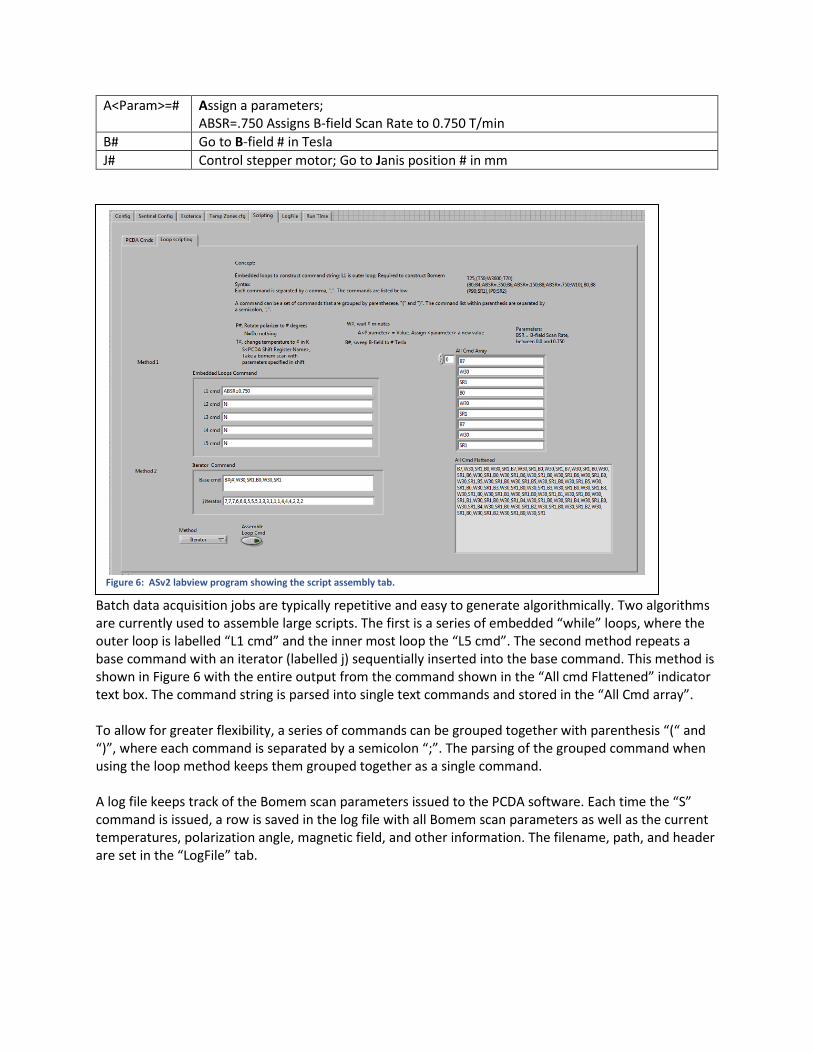
A<Param>=# Assign a parameters; ABSR=.750 Assigns B-field Scan Rate to 0.750 T/min
B# Go to B-field # in Tesla J# Control stepper motor; Go to Janis position # in mm
Batch data acquisition jobs are typically repetitive and easy to generate algorithmically. Two algorithms are currently used to assemble large scripts. The first is a series of embedded “while” loops, where the outer loop is labelled “L1 cmd” and the inner most loop the “L5 cmd”. The second method repeats a base command with an iterator (labelled j) sequentially inserted into the base command. This method is shown in Figure 6 with the entire output from the command shown in the “All cmd Flattened” indicator text box. The command string is parsed into single text commands and stored in the “All Cmd array”. To allow for greater flexibility, a series of commands can be grouped together with parenthesis “(“ and “)”, where each command is separated by a semicolon “;”. The parsing of the grouped command when using the loop method keeps them grouped together as a single command. A log file keeps track of the Bomem scan parameters issued to the PCDA software. Each time the “S” command is issued, a row is saved in the log file with all Bomem scan parameters as well as the current temperatures, polarization angle, magnetic field, and other information. The filename, path, and header are set in the “LogFile” tab.
Figure 6: ASv2 labview program showing the script assembly tab.
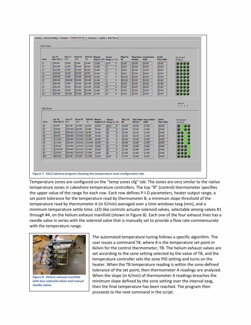
Temperature zones are configured on the “temp zones cfg” tab. The zones are very similar to the native temperature zones in Lakeshore temperature controllers. The top “B” (control) thermometer specifies the upper value of the range for each row. Each row defines P-I-D parameters, heater output range, a set point tolerance for the temperature read by thermometer B, a minimum slope threshold of the temperature read by thermometer A (in K/min) averaged over a time windows tavg (min), and a minimum temperature settle time. LED-like controls actuate solenoid valves, selectable among valves #1 through #4, on the helium exhaust manifold (shown in Figure 8). Each one of the four exhaust lines has a needle valve in series with the solenoid valve that is manually set to provide a flow rate commensurate with the temperature range.
The automated temperature tuning follows a specific algorithm. The user issues a command T#, where # is the temperature set point in Kelvin for the control thermometer, TB. The helium exhaust valves are set according to the zone setting selected by the value of TB, and the temperature controller sets the zone PID setting and turns on the heater. When the TB temperature reading is within the zone-defined tolerance of the set point, then thermometer A readings are analyzed. When the slope (in K/min) of thermometer A readings breaches the minimum slope defined by the zone setting over the interval tavg, then the final temperature has been reached. The program then proceeds to the next command in the script.
Figure 7: ASv2 labview program showing the temperature zone configuration tab.
Figure 8: Helium exhaust manifold with four solenoid valves and manual needle valves.
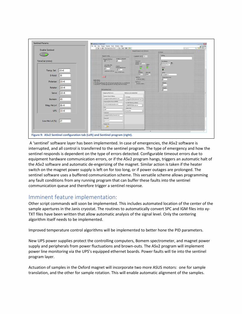
A ‘sentinel’ software layer has been implemented. In case of emergencies, the ASv2 software is interrupted, and all control is transferred to the sentinel program. The type of emergency and how the sentinel responds is dependent on the type of errors detected. Configurable timeout errors due to equipment hardware communication errors, or if the ASv2 program hangs, triggers an automatic halt of the ASv2 software and automatic de-engerizing of the magnet. Similar action is taken if the heater switch on the magnet power supply is left on for too long, or if power outages are prolonged. The sentinel software uses a buffered communication scheme. This versatile scheme allows programming any fault conditions from any running program that can buffer these faults into the sentinel communication queue and therefore trigger a sentinel response.
Imminent feature implementation: Other script commands will soon be implemented. This includes automated location of the center of the sample apertures in the Janis cryostat. The routines to automatically convert SPC and IGM files into xy-TXT files have been written that allow automatic analysis of the signal level. Only the centering algorithm itself needs to be implemented. Improved temperature control algorithms will be implemented to better hone the PID parameters. New UPS power supplies protect the controlling computers, Bomem spectrometer, and magnet power supply and peripherals from power fluctuations and brown-outs. The ASv2 program will implement power line monitoring via the UPS’s equipped ethernet boards. Power faults will tie into the sentinel program layer. Actuation of samples in the Oxford magnet will incorporate two more ASUS motors: one for sample translation, and the other for sample rotation. This will enable automatic alignment of the samples.
Figure 9: ASv2 Sentinel configuration tab (Left) and Sentinel program (right).