Embed Size (px)
Citation preview
Available at: www.etcurr.com Lesson 1.2 – Build the Tumbler
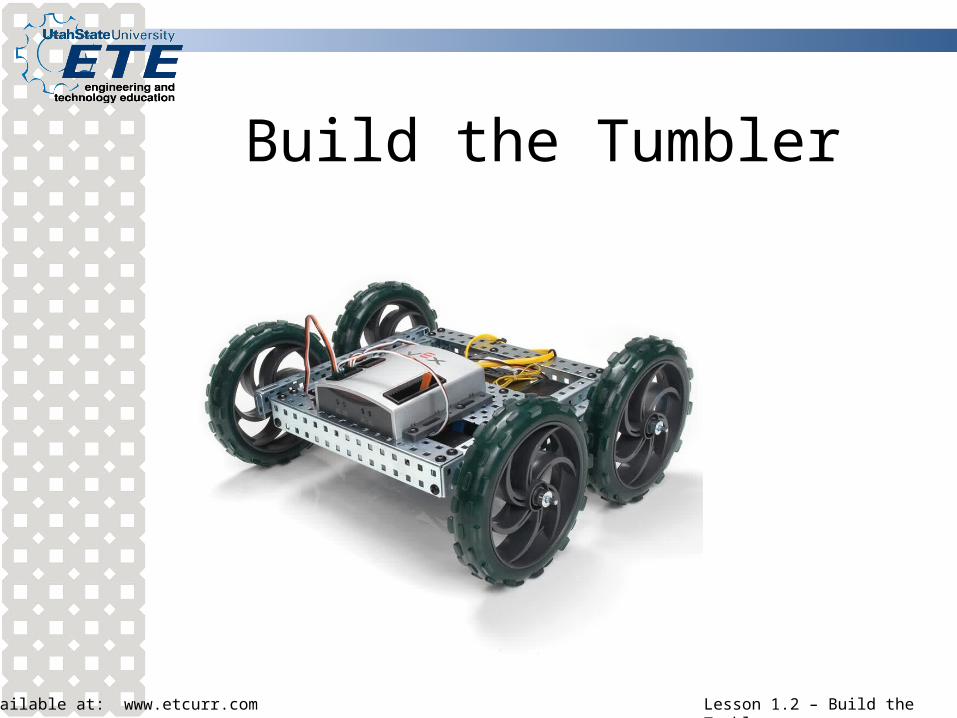
Build the Tumbler
Available at: www.etcurr.com Lesson 1.2 – Build the Tumbler
Build the Tumbler Performance Objective: Given a VEX robotics system, build the Tumbler
to the specifications in the Guide for Building the Protobot and Tumbler. Enabling Objectives: identify the following VEX parts: angle (chassis bumper), rail, plate,
standoff, shaft, nut, 6-32 x ¼ motor screw, spacer, 8-32 x ¼ screw, 8-32 x 3/8 screw, 8-32 x ½ screw, delrin bearing flat (bushing), plastic rivets, motor, motor clutch, battery tie on or battery strap, large 5” wheels, micro controller, collar
identify the following tools: Hex wrench (Allen wrench), open end wrench, nut driver
explain how metal VEX structure components are described or named explain the advantages and disadvantages of KEPS versus Nylock nuts
and VEX rivets versus screws
Available at: www.etcurr.com Lesson 1.2 – Build the Tumbler
VEX parts
The majority of the components used as structure components are made from sheetmetal
These pieces (either steel or aluminum) come in a variety of shapes and sizes and are suited to different functions
Available at: www.etcurr.com Lesson 1.2 – Build the Tumbler
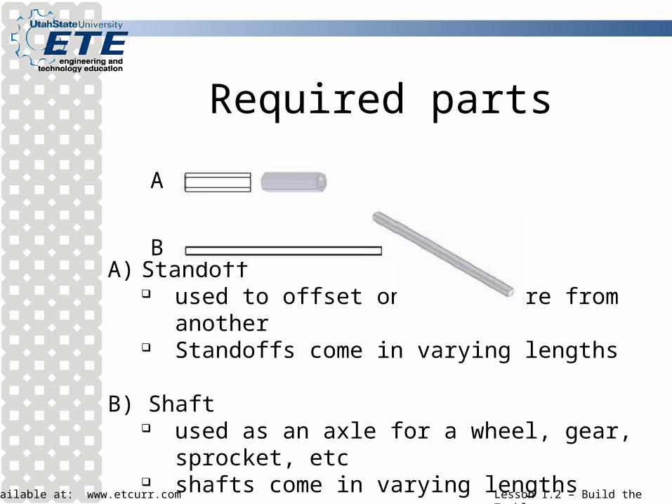
Required parts
A) Standoff used to offset one structure from another Standoffs come in varying lengths
B) Shaft used as an axle for a wheel, gear, sprocket, etc shafts come in varying lengths
A
B
Available at: www.etcurr.com Lesson 1.2 – Build the Tumbler
Required parts
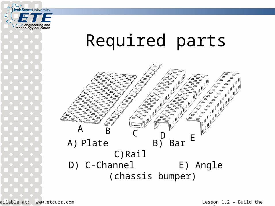
A) Plate B) Bar C)Rail D) C-Channel E) Angle (chassis bumper)
A B C ED
Available at: www.etcurr.com Lesson 1.2 – Build the Tumbler
Describing structure components
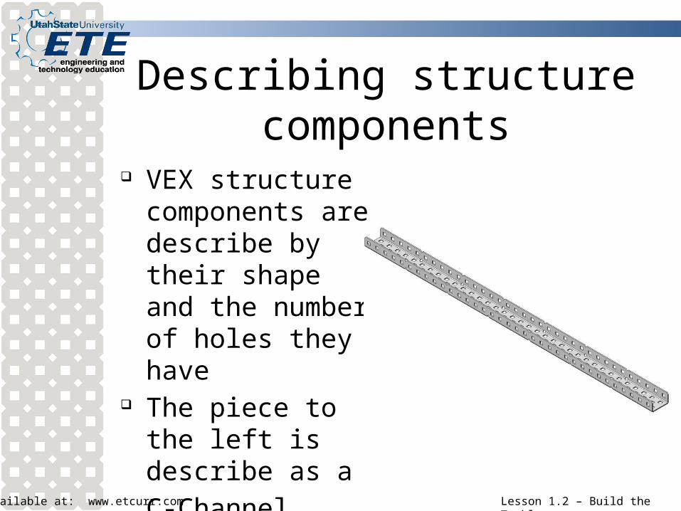
VEX structure components are describe by their shape and the number of holes they have
The piece to the left is describe as a C-Channel 1x2x1x35
Available at: www.etcurr.com Lesson 1.2 – Build the Tumbler
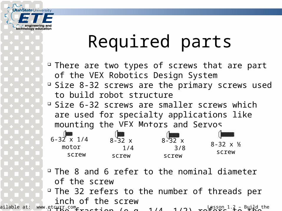
Required parts There are two types of screws that are part of the VEX Robotics
Design System Size 8-32 screws are the primary screws used to build robot
structure Size 6-32 screws are smaller screws which are used for specialty
applications like mounting the VEX Motors and Servos
6-32 x 1/4 motor screw
8-32 x 1/4screw
8-32 x 3/8screw
8-32 x ½screw
The 8 and 6 refer to the nominal diameter of the screw The 32 refers to the number of threads per inch of the screw The fraction (e.g. 1/4, 1/2) refers to the length of the screw
Available at: www.etcurr.com Lesson 1.2 – Build the Tumbler
Required parts
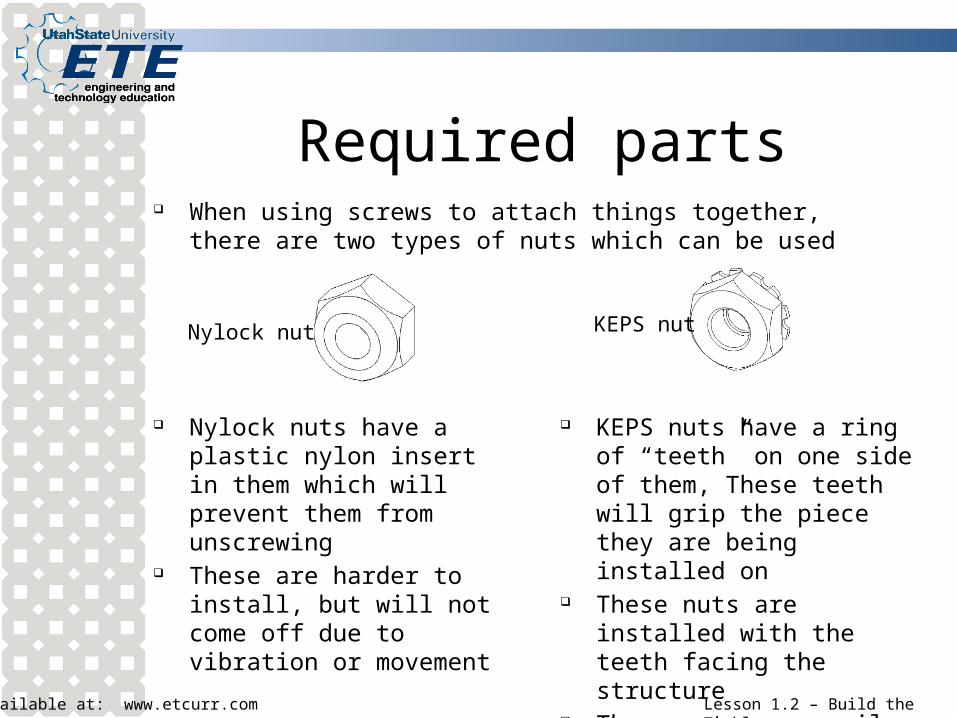
Nylock nuts have a plastic nylon insert in them which will prevent them from unscrewing
These are harder to install, but will not come off due to vibration or movement
Nylock nut KEPS nut
KEPS nuts have a ring of “teeth” on one side of them, These teeth will grip the piece they are being installed on
These nuts are installed with the teeth facing the structure
These nuts are easily installed, but can loosen up over time
When using screws to attach things together, there are two types of nuts which can be used
Available at: www.etcurr.com Lesson 1.2 – Build the Tumbler
Required parts
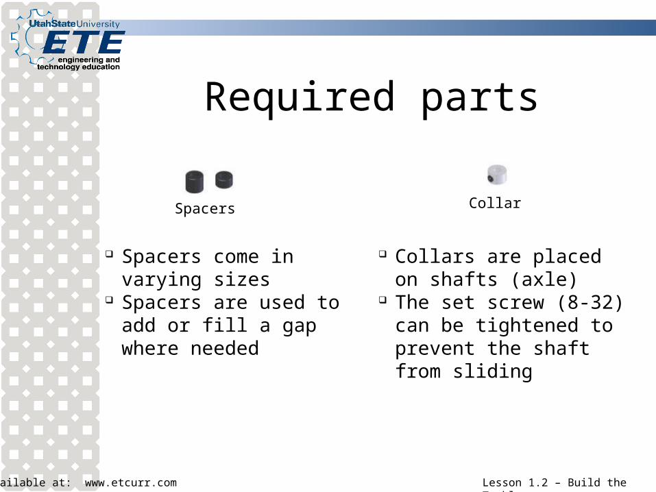
Spacers Collar
Spacers come in varying sizes Spacers are used to add or fill
a gap where needed
Collars are placed on shafts (axle)
The set screw (8-32) can be tightened to prevent the shaft from sliding
Available at: www.etcurr.com Lesson 1.2 – Build the Tumbler
Required parts
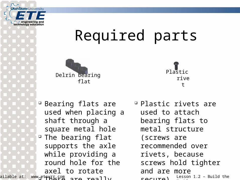
Delrin bearing flat Plastic rivet
Bearing flats are used when placing a shaft through a square metal hole
The bearing flat supports the axle while providing a round hole for the axel to rotate
These are really bushings
Plastic rivets are used to attach bearing flats to metal structure (screws are recommended over rivets, because screws hold tighter and are more secure)
Available at: www.etcurr.com Lesson 1.2 – Build the Tumbler
Required parts
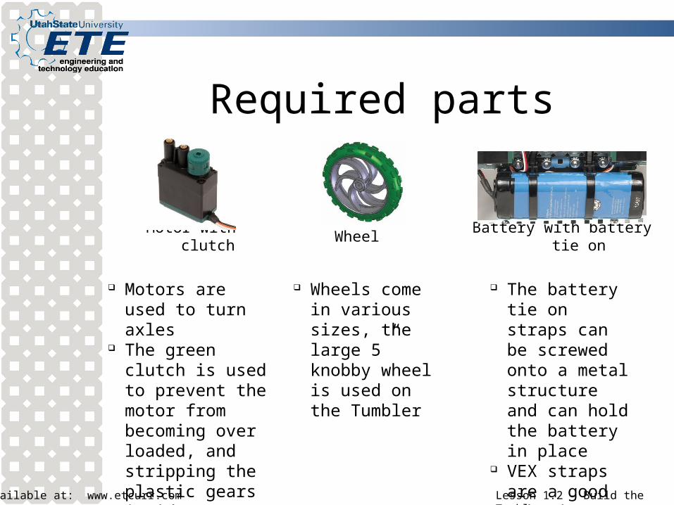
Motor with clutch Wheel Battery with battery tie on
Motors are used to turn axles
The green clutch is used to prevent the motor from becoming over loaded, and stripping the plastic gears inside
Wheels come in various sizes, the large 5” knobby wheel is used on the Tumbler
The battery tie on straps can be screwed onto a metal structure and can hold the battery in place
VEX straps are a good substitute
Available at: www.etcurr.com Lesson 1.2 – Build the Tumbler
Required parts
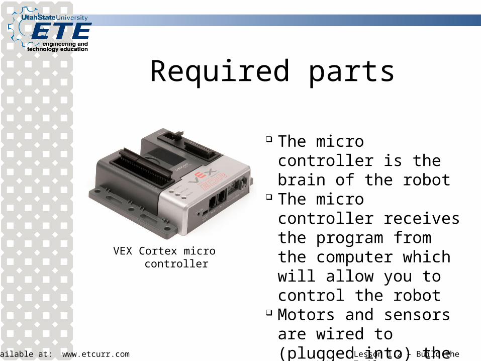
VEX Cortex micro controller
The micro controller is the brain of the robot
The micro controller receives the program from the computer which will allow you to control the robot
Motors and sensors are wired to (plugged into) the micro controller
Available at: www.etcurr.com Lesson 1.2 – Build the Tumbler
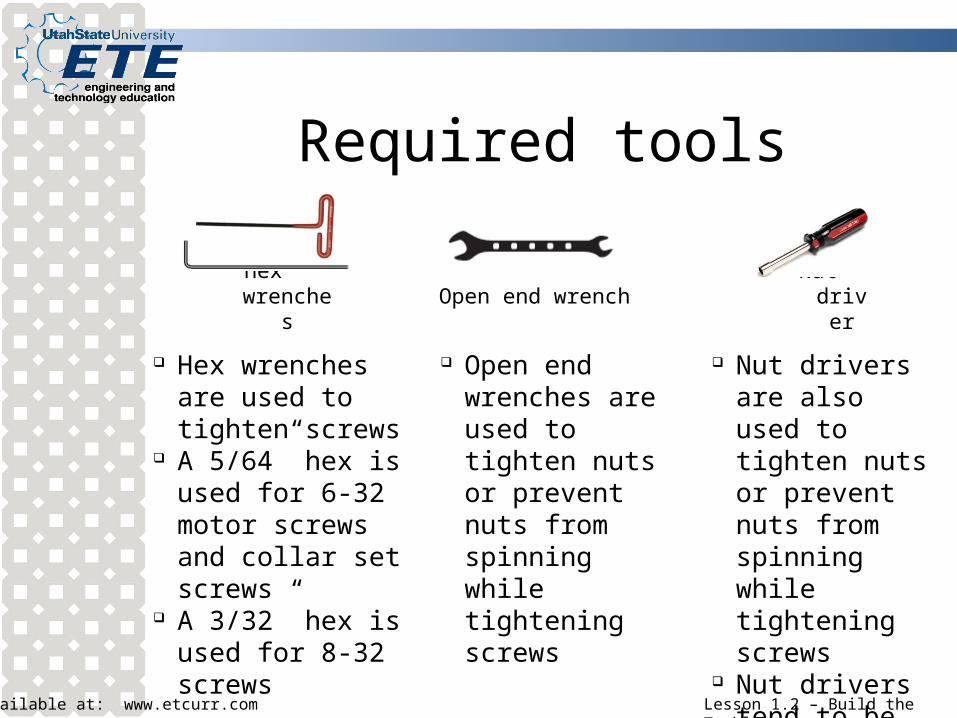
Required tools
Hex wrenches Open end wrench Nut driver
Hex wrenches are used to tighten screws
A 5/64” hex is used for 6-32 motor screws and collar set screws
A 3/32” hex is used for 8-32 screws
Open end wrenches are used to tighten nuts or prevent nuts from spinning while tightening screws
Nut drivers are also used to tighten nuts or prevent nuts from spinning while tightening screws
Nut drivers tend to be more efficient
Available at: www.etcurr.com Lesson 1.2 – Build the Tumbler
Build the Tumbler
To build the Tumbler you will need the Guide for Building the Protobot and Tumbler
Follow the steps to build the Tumbler beginning on page 29
Stop after step 11 on page 38 Once you have completed step 11, continue
onto the next slide of the PowerPoint
Available at: www.etcurr.com Lesson 1.2 – Build the Tumbler
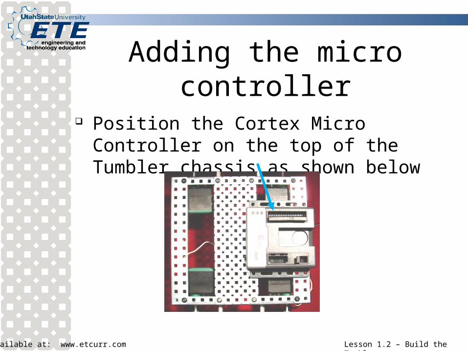
Adding the micro controller
Position the Cortex Micro Controller on the top of the Tumbler chassis as shown below
Available at: www.etcurr.com Lesson 1.2 – Build the Tumbler
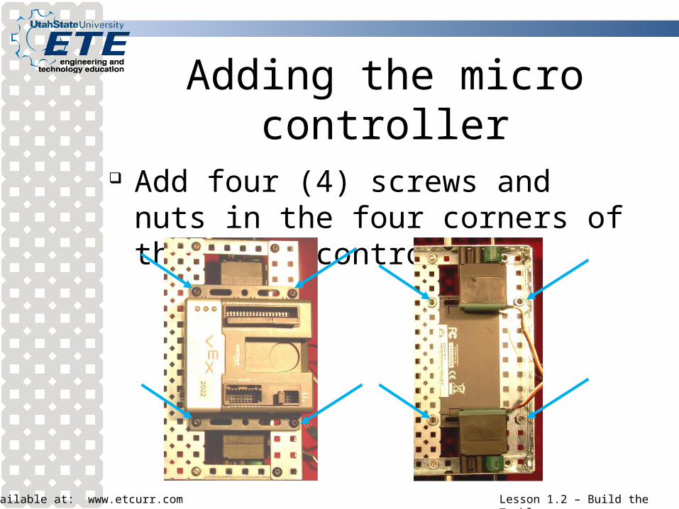
Adding the micro controller
Add four (4) screws and nuts in the four corners of the micro controller
Available at: www.etcurr.com Lesson 1.2 – Build the Tumbler
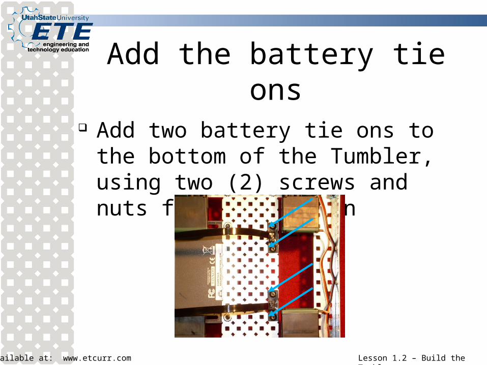
Add the battery tie ons
Add two battery tie ons to the bottom of the Tumbler, using two (2) screws and nuts for each tie on
Available at: www.etcurr.com Lesson 1.2 – Build the Tumbler
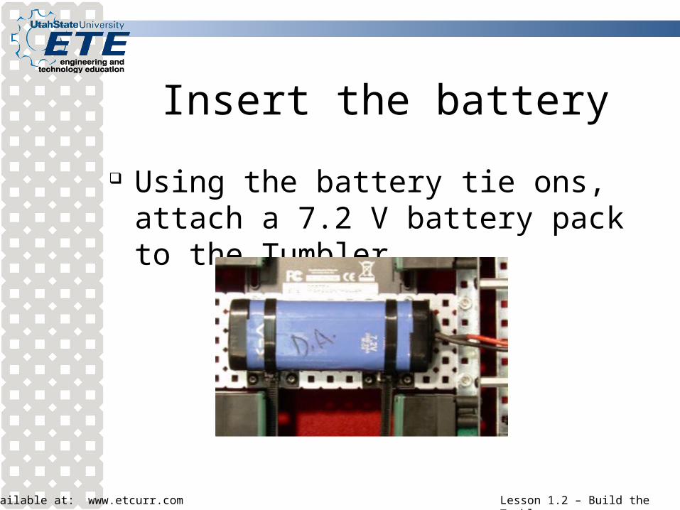
Insert the battery
Using the battery tie ons, attach a 7.2 V battery pack to the Tumbler
Available at: www.etcurr.com Lesson 1.2 – Build the Tumbler
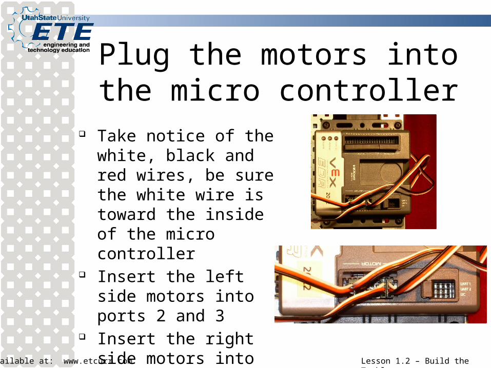
Plug the motors into the micro controller
Take notice of the white, black and red wires, be sure the white wire is toward the inside of the micro controller
Insert the left side motors into ports 2 and 3
Insert the right side motors into ports 4 and 5
Available at: www.etcurr.com Lesson 1.2 – Build the Tumbler
Almost there
You are done building the Tumbler, and are about ready to drive it!
Show the completed Tumbler to the instructor before continuing onto lesson 1.3 – Operate the Tumbler using a jumper pin