Embed Size (px)
Citation preview

USER’S MANUAL
AXIS P1311 Network Camera
AXIS P1311 User’s Manual
NoticesThis manual is intended for administrators and users of the AXIS P1311 Network Camera, and is applicable for firmware release 5.01 and later. It includes instructions for using and managing the camera on your network. Previous experience of networking will be of use when using this product. Some knowledge of UNIX or Linux-based systems may also be beneficial, for developing shell scripts and applications. Later versions of this document will be posted to the Axis Website, as required. See also the product’s online help, available via the Web-based interface.
LiabilityEvery care has been taken in the preparation of this manual. Please inform your local Axis office of any inaccuracies or omissions. Axis Communications AB cannot be held responsible for any technical or typographical errors and reserves the right to make changes to the product and manuals without prior notice. Axis Communications AB makes no warranty of any kind with regard to the material contained within this document, including, but not limited to, the implied warranties of merchantability and fitness for a particular purpose. Axis Communications AB shall not be liable nor responsible for incidental or consequential damages in connection with the furnishing, performance or use of this material.
Intellectual Property RightsAxis AB has intellectual property rights relating to technology embodied in the product described in this document. In particular, and without limitation, these intellectual property rights may include one or more of the patents listed at http://www.axis.com/patent.htm and one or more additional patents or pending patent applications in the US and other countries.
This product contains licensed third-party software. See the menu item “About” in the product’s user interface for more information.
This product contains source code copyright Apple Computer, Inc., under the terms of Apple Public Source License 2.0 (see http://www.opensource.apple.com/apsl/). The source code is available from: http://developer.apple.com/darwin/projects/bonjour/
Equipment Modifications This equipment must be installed and used in strict accordance with the instructions given in the user documentation. This equipment contains no user-serviceable components. Unauthorized equipment changes or modifications will invalidate all applicable regulatory certifications and approvals.
Trademark AcknowledgmentsApple, Boa, Bonjour, Ethernet, Internet Explorer, Linux, Microsoft, Mozilla, Netscape Navigator, OS/2, Real, QuickTime, UNIX, Windows, WWW are registered trademarks of the respective holders. Java and all Java-based trademarks and logos are trademarks or registered trademarks of Sun Microsystems, Inc. in the United States and other countries. Axis Communications AB is independent of Sun Microsystems Inc. UPnPTM is a certification mark of the UPnPTM Implementers Corporation.
SupportShould you require any technical assistance, please contact your Axis reseller. If your questions cannot be answered immediately, your reseller will forward your queries through the appropriate channels to ensure a rapid response. If you are connected to the Internet, you can:• download user documentation and firmware updates• find answers to resolved problems in the FAQ database. Search by
product, category, or phrases• report problems to Axis support by logging in to your private support
area• visit Axis Support at www.axis.com/techsup
AXIS P1311 Network Camera User’s ManualRev. 1.5
Copyright© Axis Communications AB, 2008-2010September 2010 Part no. 40502
3
AXIS P1311 - Table of contents
ContentsProduct Description . . . . . . . . . . . . . . . . . . . . . . . . . . . . . . . . . . . . . . . . . . . . . . . . . . . . . . . . . . . . . . . . . . . . . . . . . . . . . . . . 4
Key features . . . . . . . . . . . . . . . . . . . . . . . . . . . . . . . . . . . . . . . . . . . . . . . . . . . . . . . . . . . . . . . . . . . . . . . . . . . . . . 4Overview . . . . . . . . . . . . . . . . . . . . . . . . . . . . . . . . . . . . . . . . . . . . . . . . . . . . . . . . . . . . . . . . . . . . . . . . . . . . . . . . . 4LED indicators . . . . . . . . . . . . . . . . . . . . . . . . . . . . . . . . . . . . . . . . . . . . . . . . . . . . . . . . . . . . . . . . . . . . . . . . . . . . . 5
Accessing the Camera . . . . . . . . . . . . . . . . . . . . . . . . . . . . . . . . . . . . . . . . . . . . . . . . . . . . . . . . . . . . . . . . . . . . . . . . . . . . . . 6Access from a browser . . . . . . . . . . . . . . . . . . . . . . . . . . . . . . . . . . . . . . . . . . . . . . . . . . . . . . . . . . . . . . . . . . . . . . 6Setting the root password . . . . . . . . . . . . . . . . . . . . . . . . . . . . . . . . . . . . . . . . . . . . . . . . . . . . . . . . . . . . . . . . . . . 7Access from the Internet . . . . . . . . . . . . . . . . . . . . . . . . . . . . . . . . . . . . . . . . . . . . . . . . . . . . . . . . . . . . . . . . . . . . 7The Live View page . . . . . . . . . . . . . . . . . . . . . . . . . . . . . . . . . . . . . . . . . . . . . . . . . . . . . . . . . . . . . . . . . . . . . . . . . 9
Video Streams . . . . . . . . . . . . . . . . . . . . . . . . . . . . . . . . . . . . . . . . . . . . . . . . . . . . . . . . . . . . . . . . . . . . . . . . . . . . . . . . . . . 11How to stream MPEG-4/H.264 . . . . . . . . . . . . . . . . . . . . . . . . . . . . . . . . . . . . . . . . . . . . . . . . . . . . . . . . . . . . . . 11Motion JPEG . . . . . . . . . . . . . . . . . . . . . . . . . . . . . . . . . . . . . . . . . . . . . . . . . . . . . . . . . . . . . . . . . . . . . . . . . . . . . 12Alternative methods of accessing the video stream . . . . . . . . . . . . . . . . . . . . . . . . . . . . . . . . . . . . . . . . . . . . . 12
Video & Audio settings . . . . . . . . . . . . . . . . . . . . . . . . . . . . . . . . . . . . . . . . . . . . . . . . . . . . . . . . . . . . . . . . . . . . . . . . . . . . 13Video Stream . . . . . . . . . . . . . . . . . . . . . . . . . . . . . . . . . . . . . . . . . . . . . . . . . . . . . . . . . . . . . . . . . . . . . . . . . . . . 13Stream Profiles . . . . . . . . . . . . . . . . . . . . . . . . . . . . . . . . . . . . . . . . . . . . . . . . . . . . . . . . . . . . . . . . . . . . . . . . . . . 14Camera Settings . . . . . . . . . . . . . . . . . . . . . . . . . . . . . . . . . . . . . . . . . . . . . . . . . . . . . . . . . . . . . . . . . . . . . . . . . . 14Overlay Image . . . . . . . . . . . . . . . . . . . . . . . . . . . . . . . . . . . . . . . . . . . . . . . . . . . . . . . . . . . . . . . . . . . . . . . . . . . . 15Privacy mask . . . . . . . . . . . . . . . . . . . . . . . . . . . . . . . . . . . . . . . . . . . . . . . . . . . . . . . . . . . . . . . . . . . . . . . . . . . . . 16Audio Settings . . . . . . . . . . . . . . . . . . . . . . . . . . . . . . . . . . . . . . . . . . . . . . . . . . . . . . . . . . . . . . . . . . . . . . . . . . . 16
Live View Config . . . . . . . . . . . . . . . . . . . . . . . . . . . . . . . . . . . . . . . . . . . . . . . . . . . . . . . . . . . . . . . . . . . . . . . . . . . . . . . . . . 18Layout . . . . . . . . . . . . . . . . . . . . . . . . . . . . . . . . . . . . . . . . . . . . . . . . . . . . . . . . . . . . . . . . . . . . . . . . . . . . . . . . . . 18
Events . . . . . . . . . . . . . . . . . . . . . . . . . . . . . . . . . . . . . . . . . . . . . . . . . . . . . . . . . . . . . . . . . . . . . . . . . . . . . . . . . . . . . . . . . . 20Event Servers . . . . . . . . . . . . . . . . . . . . . . . . . . . . . . . . . . . . . . . . . . . . . . . . . . . . . . . . . . . . . . . . . . . . . . . . . . . . 20Event Types . . . . . . . . . . . . . . . . . . . . . . . . . . . . . . . . . . . . . . . . . . . . . . . . . . . . . . . . . . . . . . . . . . . . . . . . . . . . . . 20Camera tampering . . . . . . . . . . . . . . . . . . . . . . . . . . . . . . . . . . . . . . . . . . . . . . . . . . . . . . . . . . . . . . . . . . . . . . . . 22Motion Detection . . . . . . . . . . . . . . . . . . . . . . . . . . . . . . . . . . . . . . . . . . . . . . . . . . . . . . . . . . . . . . . . . . . . . . . . . 23Port Status . . . . . . . . . . . . . . . . . . . . . . . . . . . . . . . . . . . . . . . . . . . . . . . . . . . . . . . . . . . . . . . . . . . . . . . . . . . . . . 24
Recording List . . . . . . . . . . . . . . . . . . . . . . . . . . . . . . . . . . . . . . . . . . . . . . . . . . . . . . . . . . . . . . . . . . . . . . . . . . . . . . . . . . . . 25System Options . . . . . . . . . . . . . . . . . . . . . . . . . . . . . . . . . . . . . . . . . . . . . . . . . . . . . . . . . . . . . . . . . . . . . . . . . . . . . . . . . . 26
Security . . . . . . . . . . . . . . . . . . . . . . . . . . . . . . . . . . . . . . . . . . . . . . . . . . . . . . . . . . . . . . . . . . . . . . . . . . . . . . . . . 26Date & Time . . . . . . . . . . . . . . . . . . . . . . . . . . . . . . . . . . . . . . . . . . . . . . . . . . . . . . . . . . . . . . . . . . . . . . . . . . . . . 27Network . . . . . . . . . . . . . . . . . . . . . . . . . . . . . . . . . . . . . . . . . . . . . . . . . . . . . . . . . . . . . . . . . . . . . . . . . . . . . . . . . 28Storage . . . . . . . . . . . . . . . . . . . . . . . . . . . . . . . . . . . . . . . . . . . . . . . . . . . . . . . . . . . . . . . . . . . . . . . . . . . . . . . . . 32Ports & Devices . . . . . . . . . . . . . . . . . . . . . . . . . . . . . . . . . . . . . . . . . . . . . . . . . . . . . . . . . . . . . . . . . . . . . . . . . . . 32LED . . . . . . . . . . . . . . . . . . . . . . . . . . . . . . . . . . . . . . . . . . . . . . . . . . . . . . . . . . . . . . . . . . . . . . . . . . . . . . . . . . . . . 32Maintenance . . . . . . . . . . . . . . . . . . . . . . . . . . . . . . . . . . . . . . . . . . . . . . . . . . . . . . . . . . . . . . . . . . . . . . . . . . . . . 33Support . . . . . . . . . . . . . . . . . . . . . . . . . . . . . . . . . . . . . . . . . . . . . . . . . . . . . . . . . . . . . . . . . . . . . . . . . . . . . . . . . 33Advanced . . . . . . . . . . . . . . . . . . . . . . . . . . . . . . . . . . . . . . . . . . . . . . . . . . . . . . . . . . . . . . . . . . . . . . . . . . . . . . . . 34
About . . . . . . . . . . . . . . . . . . . . . . . . . . . . . . . . . . . . . . . . . . . . . . . . . . . . . . . . . . . . . . . . . . . . . . . . . . . . . . . . . . . . . . . . . . 35Resetting to Factory Default Settings . . . . . . . . . . . . . . . . . . . . . . . . . . . . . . . . . . . . . . . . . . . . . . . . . . . . . . . . . . . . . . . . 35Unit connectors . . . . . . . . . . . . . . . . . . . . . . . . . . . . . . . . . . . . . . . . . . . . . . . . . . . . . . . . . . . . . . . . . . . . . . . . . . . . . . . . . . 36Troubleshooting . . . . . . . . . . . . . . . . . . . . . . . . . . . . . . . . . . . . . . . . . . . . . . . . . . . . . . . . . . . . . . . . . . . . . . . . . . . . . . . . . . 38
Checking the firmware . . . . . . . . . . . . . . . . . . . . . . . . . . . . . . . . . . . . . . . . . . . . . . . . . . . . . . . . . . . . . . . . . . . . . 38Upgrading the firmware . . . . . . . . . . . . . . . . . . . . . . . . . . . . . . . . . . . . . . . . . . . . . . . . . . . . . . . . . . . . . . . . . . . . 38Symptoms, possible causes, and remedial actions . . . . . . . . . . . . . . . . . . . . . . . . . . . . . . . . . . . . . . . . . . . . . . . 40
Technical Specifications . . . . . . . . . . . . . . . . . . . . . . . . . . . . . . . . . . . . . . . . . . . . . . . . . . . . . . . . . . . . . . . . . . . . . . . . . . . 43General performance considerations . . . . . . . . . . . . . . . . . . . . . . . . . . . . . . . . . . . . . . . . . . . . . . . . . . . . . . . . . 45
Glossary of Terms . . . . . . . . . . . . . . . . . . . . . . . . . . . . . . . . . . . . . . . . . . . . . . . . . . . . . . . . . . . . . . . . . . . . . . . . . . . . . . . . . 46Index . . . . . . . . . . . . . . . . . . . . . . . . . . . . . . . . . . . . . . . . . . . . . . . . . . . . . . . . . . . . . . . . . . . . . . . . . . . . . . . . . . . . . . . . . . . 52
AXIS P1311 - Product Description
Product Description
Key features• Superior image quality
AXIS P1311 offers superior image quality with progressive scan, providing crisp and clear images of both illuminated and dark areas.
• Multiple H.264, MPEG-4 and Motion JPEG streams AXIS P1311 can provide several independent H.264, MPEG-4 and Motion JPEG streams for different quality needs and bandwidth constraints. It is possible to view images in the highest quality and full frame rate simultaneously with a video stream configured for optimized storage, optionally at a lower resolution or frame rate, or a higher compression level. H.264 also offers significantly reduced bit rate compared with MPEG-4 Part-2. Motion JPEG images can simul-taneously be provided in full frame rate for easy extraction of high-quality still images.
• Intelligent video capabilities AXIS P1311 Network Camera offers intelligent capabilities such as enhanced video motion detection, two-way audio including audio detection support, and detection of camera tampering attempts like blocking or spray-painting. The camera also provides capacity for third party analytics modules.
• Improved security AXIS P1311 logs all user access, and lists currently connected users. AXIS P1311 also includes hardware accelerated crypto, which implies that full frame rate video can be provided over HTTPS.
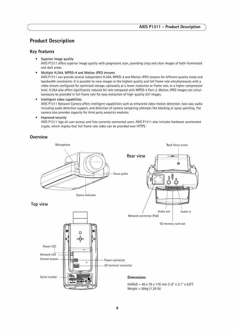
Overview
Dimensions
HxWxD = 46 x 78 x 176 mm (1.8" x 3.1" x 6.9") Weight = 584g (1.29 lb)
Network connector (PoE)
Focus puller
Status indicator
Microphone
Power LED
Network LED
Serial number
Top view
Rear view
Control button
I/O terminal connector
Power connector
Back focus screw
Audio inAudio out
SD memory card slot
4

AXIS P1311 - Product Description
LED indicators
Status LED for lens adjustment
LED Color Indication
Network Green Steady for connection to a 100 Mbit/s network. Flashes for network activity.
Amber Steady for connection to 10 Mbit/s network. Flashes for network activity.
Unlit No network connection.
Status Green Steady green for normal operation.Note: The Status LED can be configured to be unlit during normal operation, or to flash only when the camera is accessed. To configure, go to Setup > System Options > LED settings. See the online help files for more information.
Amber Steady during startup, during reset to factory default or when restoring settings.
Red Slow flash for failed upgrade.
Power Green Normal operation.
Amber Flashes green/amber during firmware upgrade.
Status LED Color Indication
Green Step 4: Focus Assistant is enabledStep 6: The lens is optimally adjusted
Amber Step 4: The Camera has been moved, or an object has been inserted in front of the lens. Exit and restart the Focus Assistant.Step 6: The lens is less optimally adjusted
Red Step 4: The Camera has been moved, or an object has been inserted in front of the lens. Exit and restart the Focus Assistant.Step 6: The lens is poorly adjusted
5
AXIS P1311 - Accessing the Camera
Accessing the CameraTo install the AXIS P1311 network cameras, refer to the installation guide supplied with your product.
The network camera can be used with most standard operating systems and browsers. The recommended browser is Microsoft Internet Explorer with Windows, Safari with Macintosh and Firefox with other operating systems. See Technical Specifications, on page 43.
Notes:
• To view streaming video in Microsoft Internet Explorer, set your browser to allow ActiveX controls and install AXIS Media Control (AMC) on your workstation.
• QuickTimeTM is also supported for viewing H.264 and MPEG-4 streams and for audio.• If your computer restricts the use of additional software components, the camera can be configured to use a Java
applet for viewing Motion JPEG.• The network camera includes one (1) H.264 decoder license and one (1) MPEG-4 decoder license for viewing video
streams, and (1) AAC audio license. These licenses are automatically installed with AMC. The administrator can disable the installation of the decoders, to prevent installation of unlicensed copies.
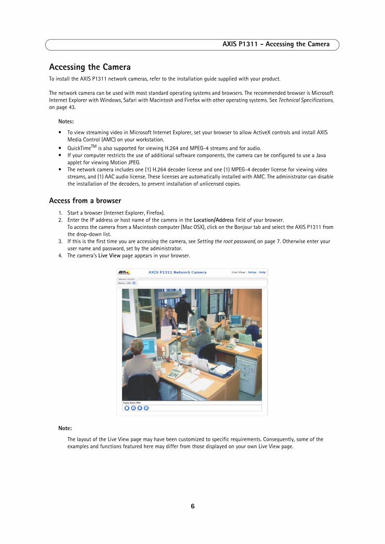
Access from a browser 1. Start a browser (Internet Explorer, Firefox).2. Enter the IP address or host name of the camera in the Location/Address field of your browser.
To access the camera from a Macintosh computer (Mac OSX), click on the Bonjour tab and select the AXIS P1311 from the drop-down list.
3. If this is the first time you are accessing the camera, see Setting the root password, on page 7. Otherwise enter your user name and password, set by the administrator.
4. The camera’s Live View page appears in your browser.
Note:
The layout of the Live View page may have been customized to specific requirements. Consequently, some of the examples and functions featured here may differ from those displayed on your own Live View page.
6
AXIS P1311 - Accessing the Camera
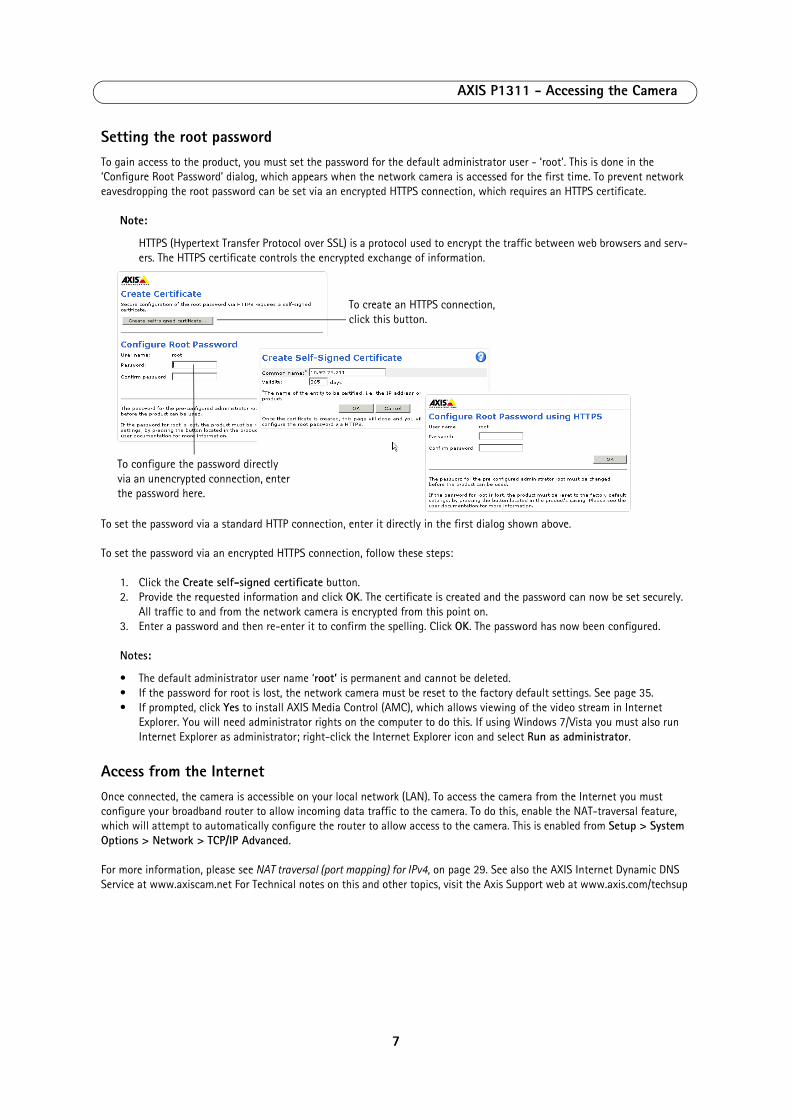
Setting the root passwordTo gain access to the product, you must set the password for the default administrator user - ‘root’. This is done in the ‘Configure Root Password’ dialog, which appears when the network camera is accessed for the first time. To prevent network eavesdropping the root password can be set via an encrypted HTTPS connection, which requires an HTTPS certificate.
Note:
HTTPS (Hypertext Transfer Protocol over SSL) is a protocol used to encrypt the traffic between web browsers and serv-ers. The HTTPS certificate controls the encrypted exchange of information.
To set the password via a standard HTTP connection, enter it directly in the first dialog shown above.
To set the password via an encrypted HTTPS connection, follow these steps:
1. Click the Create self-signed certificate button.2. Provide the requested information and click OK. The certificate is created and the password can now be set securely.
All traffic to and from the network camera is encrypted from this point on.3. Enter a password and then re-enter it to confirm the spelling. Click OK. The password has now been configured.
Notes:
• The default administrator user name ‘root’ is permanent and cannot be deleted.• If the password for root is lost, the network camera must be reset to the factory default settings. See page 35.• If prompted, click Yes to install AXIS Media Control (AMC), which allows viewing of the video stream in Internet
Explorer. You will need administrator rights on the computer to do this. If using Windows 7/Vista you must also run Internet Explorer as administrator; right-click the Internet Explorer icon and select Run as administrator.
Access from the InternetOnce connected, the camera is accessible on your local network (LAN). To access the camera from the Internet you must configure your broadband router to allow incoming data traffic to the camera. To do this, enable the NAT-traversal feature, which will attempt to automatically configure the router to allow access to the camera. This is enabled from Setup > System Options > Network > TCP/IP Advanced.
For more information, please see NAT traversal (port mapping) for IPv4, on page 29. See also the AXIS Internet Dynamic DNS Service at www.axiscam.net For Technical notes on this and other topics, visit the Axis Support web at www.axis.com/techsup
To configure the password directly via an unencrypted connection, enter the password here.
To create an HTTPS connection, click this button.
7
AXIS P1311 - Accessing the Camera
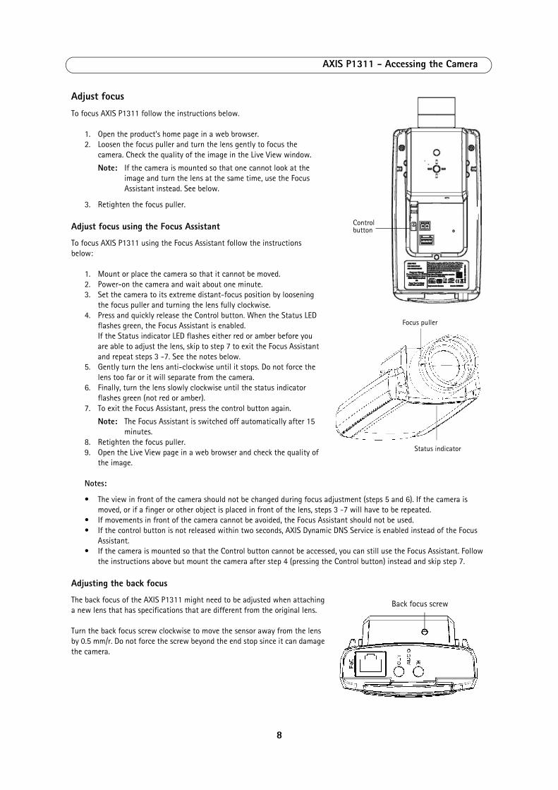
Adjust focus
To focus AXIS P1311 follow the instructions below.
1. Open the product’s home page in a web browser.2. Loosen the focus puller and turn the lens gently to focus the
camera. Check the quality of the image in the Live View window.
Note: If the camera is mounted so that one cannot look at the image and turn the lens at the same time, use the Focus Assistant instead. See below.
3. Retighten the focus puller.
Adjust focus using the Focus Assistant
To focus AXIS P1311 using the Focus Assistant follow the instructions below:
1. Mount or place the camera so that it cannot be moved. 2. Power-on the camera and wait about one minute. 3. Set the camera to its extreme distant-focus position by loosening
the focus puller and turning the lens fully clockwise.4. Press and quickly release the Control button. When the Status LED
flashes green, the Focus Assistant is enabled. If the Status indicator LED flashes either red or amber before you are able to adjust the lens, skip to step 7 to exit the Focus Assistant and repeat steps 3 -7. See the notes below.
5. Gently turn the lens anti-clockwise until it stops. Do not force the lens too far or it will separate from the camera.
6. Finally, turn the lens slowly clockwise until the status indicator flashes green (not red or amber).
7. To exit the Focus Assistant, press the control button again.
Note: The Focus Assistant is switched off automatically after 15 minutes.
8. Retighten the focus puller.9. Open the Live View page in a web browser and check the quality of
the image.
Notes:
• The view in front of the camera should not be changed during focus adjustment (steps 5 and 6). If the camera is moved, or if a finger or other object is placed in front of the lens, steps 3 -7 will have to be repeated.
• If movements in front of the camera cannot be avoided, the Focus Assistant should not be used. • If the control button is not released within two seconds, AXIS Dynamic DNS Service is enabled instead of the Focus
Assistant.• If the camera is mounted so that the Control button cannot be accessed, you can still use the Focus Assistant. Follow
the instructions above but mount the camera after step 4 (pressing the Control button) instead and skip step 7.
Adjusting the back focus
The back focus of the AXIS P1311 might need to be adjusted when attaching a new lens that has specifications that are different from the original lens.
Turn the back focus screw clockwise to move the sensor away from the lens by 0.5 mm/r. Do not force the screw beyond the end stop since it can damage the camera.
Focus puller
Status indicator
Control button
Back focus screw
8
AXIS P1311 - Accessing the Camera
The Live View pageHow you customize the Live View page determines which buttons are visible. Not all the buttons described below will show up unless configured to do so.
General controls
AXIS Media Control toolbar
The AMC viewer toolbar (AXIS Media Control) is available in Microsoft Internet Explorer only. See AXIS Media Control (AMC), on page 12 for more information. AMC displays the following buttons:
AMC audio controls monitor the client computer’s speaker output. These controls are only available when audio is enabled.
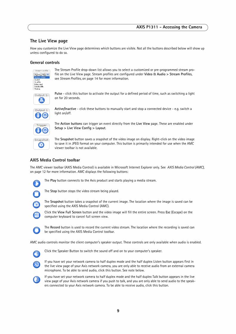
The Stream Profile drop-down list allows you to select a customized or pre-programmed stream pro-file on the Live View page. Stream profiles are configured under Video & Audio > Stream Profiles, see Stream Profiles, on page 14 for more information.
Pulse - click this button to activate the output for a defined period of time, such as switching a light on for 20 seconds.
Active/Inactive - click these buttons to manually start and stop a connected device - e.g. switch a light on/off.
The Action buttons can trigger an event directly from the Live View page. These are enabled under Setup > Live View Config > Layout.
The Snapshot button saves a snapshot of the video image on display. Right-click on the video image to save it in JPEG format on your computer. This button is primarily intended for use when the AMC viewer toolbar is not available.
The Play button connects to the Axis product and starts playing a media stream.
The Stop button stops the video stream being played.
The Snapshot button takes a snapshot of the current image. The location where the image is saved can be specified using the AXIS Media Control (AMC).
Click the View Full Screen button and the video image will fill the entire screen. Press Esc (Escape) on the computer keyboard to cancel full screen view.
The Record button is used to record the current video stream. The location where the recording is saved can be specified using the AXIS Media Control toolbar.
Click the Speaker Button to switch the sound off and on to your computer's speaker.
If you have set your network camera to half duplex mode and the half duplex Listen button appears first in the live view page of your Axis network camera, you are only able to receive audio from an external camera microphone. To be able to send audio, click this button. See note below.
If you have set your network camera to half duplex mode and the half duplex Talk button appears in the live view page of your Axis network camera if you push to talk, and you are only able to send audio to the speak-ers connected to your Axis network camera. To be able to receive audio, click this button.
9

AXIS P1311 - Accessing the Camera
Note:
In Simplex – speaker only or microphone only mode, you can use either the Microphone button or the half duplex Talk button to stop sending audio to the network camera. To send audio, both buttons must be enabled.
Click the Microphone button to switch the sound off and on to your computer's microphone. In Simplex - Network Camera speaker only mode, you can click this button to stop sending audio to the network camera. See note below.
Use this scale to control the volume of the speakers and the microphone.
10
AXIS P1311 - Video Streams
Video StreamsThe network camera provides several image and video stream formats. Your requirements and the properties of your network will determine the type you use.
The Live View page in the network camera provides access to H.264, Motion JPEG, and MPEG-4 video streams, and to the list of available stream profiles. Other applications and clients can also access these video streams/images directly, without going via the Live View page.
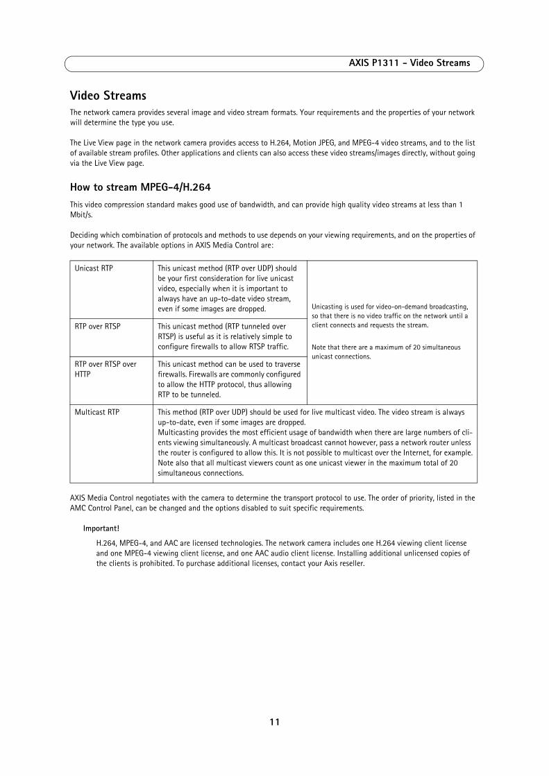
How to stream MPEG-4/H.264This video compression standard makes good use of bandwidth, and can provide high quality video streams at less than 1 Mbit/s.
Deciding which combination of protocols and methods to use depends on your viewing requirements, and on the properties of your network. The available options in AXIS Media Control are:
AXIS Media Control negotiates with the camera to determine the transport protocol to use. The order of priority, listed in the AMC Control Panel, can be changed and the options disabled to suit specific requirements.
Important!
H.264, MPEG-4, and AAC are licensed technologies. The network camera includes one H.264 viewing client license and one MPEG-4 viewing client license, and one AAC audio client license. Installing additional unlicensed copies of the clients is prohibited. To purchase additional licenses, contact your Axis reseller.
Unicast RTP This unicast method (RTP over UDP) should be your first consideration for live unicast video, especially when it is important to always have an up-to-date video stream, even if some images are dropped. Unicasting is used for video-on-demand broadcasting,
so that there is no video traffic on the network until a client connects and requests the stream.
Note that there are a maximum of 20 simultaneous unicast connections.
RTP over RTSP This unicast method (RTP tunneled over RTSP) is useful as it is relatively simple to configure firewalls to allow RTSP traffic.
RTP over RTSP over HTTP
This unicast method can be used to traverse firewalls. Firewalls are commonly configured to allow the HTTP protocol, thus allowing RTP to be tunneled.
Multicast RTP This method (RTP over UDP) should be used for live multicast video. The video stream is always up-to-date, even if some images are dropped.Multicasting provides the most efficient usage of bandwidth when there are large numbers of cli-ents viewing simultaneously. A multicast broadcast cannot however, pass a network router unless the router is configured to allow this. It is not possible to multicast over the Internet, for example.Note also that all multicast viewers count as one unicast viewer in the maximum total of 20 simultaneous connections.
11
AXIS P1311 - Video Streams
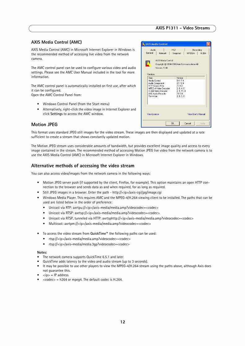
AXIS Media Control (AMC)
AXIS Media Control (AMC) in Microsoft Internet Explorer in Windows is the recommended method of accessing live video from the network camera.
The AMC control panel can be used to configure various video and audio settings. Please see the AMC User Manual included in the tool for more information.
The AMC control panel is automatically installed on first use, after which it can be configured. Open the AMC Control Panel from:
• Windows Control Panel (from the Start menu)• Alternatively, right-click the video image in Internet Explorer and
click Settings to access the AMC window.
Motion JPEGThis format uses standard JPEG still images for the video stream. These images are then displayed and updated at a rate sufficient to create a stream that shows constantly updated motion.
The Motion JPEG stream uses considerable amounts of bandwidth, but provides excellent image quality and access to every image contained in the stream. The recommended method of accessing Motion JPEG live video from the network camera is to use the AXIS Media Control (AMC) in Microsoft Internet Explorer in Windows.
Alternative methods of accessing the video streamYou can also access video/images from the network camera in the following ways:
• Motion JPEG server push (if supported by the client, Firefox, for example). This option maintains an open HTTP con-nection to the browser and sends data as and when required, for as long as required.
• Still JPEG images in a browser. Enter the path - http://<ip>/axis-cgi/jpg/image.cgi• Windows Media Player. This requires AMC and the MPEG-4/H.264 viewing client to be installed. The paths that can be
used are listed below in the order of preference:• Unicast via RTP: axrtpu://<ip>/axis-media/media.amp?videocodec=<codec>• Unicast via RTSP: axrtsp://<ip>/axis-media/media.amp?videocodec=<codec>• Unicast via RTSP, tunneled via HTTP: axrtsphttp://<ip>/axis-media/media.amp?videocodec=<codec>• Multicast: axrtpm://<ip>/axis-media/media.amp?videocodec=<codec>
• To access the video stream from QuickTime™ the following paths can be used:
• rtsp://<ip>/axis-media/media.amp?videocodec=<codec>• rtsp://<ip>/axis-media/media.3gp?videocodec=<codec>
Notes: • The network camera supports QuickTime 6.5.1 and later.
• QuickTime adds latency to the video and audio stream (up to 3 seconds).• It may be possible to use other players to view the MPEG-4/H.264 stream using the paths above, although Axis does
not guarantee this.• <ip> = IP address• <codec> = h264 or mpeg4. The default codec is H.264.
12
AXIS P1311 - Video & Audio settings
Video & Audio settingsThis section describes how to configure the camera, and is intended for product Administrators, who have unrestricted access to all settings; and Operators, who have access to the settings for Basic Setup, Video & Audio and Events.
You can configure the camera by clicking Setup in the top right-hand corner of the Live View page. Click on this page to access the online help that explains the setup tools.
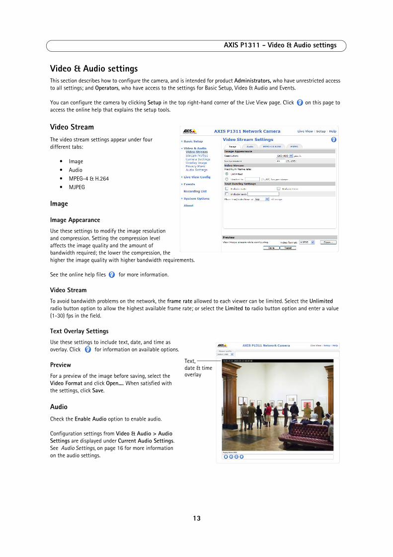
Video StreamThe video stream settings appear under four different tabs:
• Image • Audio • MPEG-4 & H.264 • MJPEG
Image
Image Appearance
Use these settings to modify the image resolution and compression. Setting the compression level affects the image quality and the amount of bandwidth required; the lower the compression, the higher the image quality with higher bandwidth requirements.
See the online help files for more information.
Video Stream
To avoid bandwidth problems on the network, the frame rate allowed to each viewer can be limited. Select the Unlimited radio button option to allow the highest available frame rate; or select the Limited to radio button option and enter a value (1-30) fps in the field.
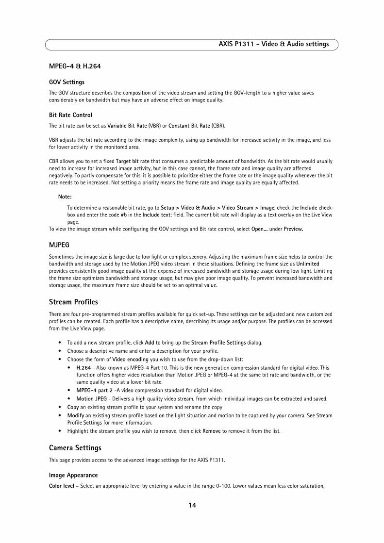
Text Overlay Settings
Use these settings to include text, date, and time as overlay. Click for information on available options.
Preview
For a preview of the image before saving, select the Video Format and click Open.... When satisfied with the settings, click Save.
Audio
Check the Enable Audio option to enable audio.
Configuration settings from Video & Audio > Audio Settings are displayed under Current Audio Settings. See Audio Settings, on page 16 for more information on the audio settings.
Text,
overlaydate & time
13
AXIS P1311 - Video & Audio settings
MPEG-4 & H.264
GOV Settings
The GOV structure describes the composition of the video stream and setting the GOV-length to a higher value saves considerably on bandwidth but may have an adverse effect on image quality.
Bit Rate Control
The bit rate can be set as Variable Bit Rate (VBR) or Constant Bit Rate (CBR).
VBR adjusts the bit rate according to the image complexity, using up bandwidth for increased activity in the image, and less for lower activity in the monitored area.
CBR allows you to set a fixed Target bit rate that consumes a predictable amount of bandwidth. As the bit rate would usually need to increase for increased image activity, but in this case cannot, the frame rate and image quality are affected negatively. To partly compensate for this, it is possible to prioritize either the frame rate or the image quality whenever the bit rate needs to be increased. Not setting a priority means the frame rate and image quality are equally affected.
Note:
To determine a reasonable bit rate, go to Setup > Video & Audio > Video Stream > Image, check the Include check-box and enter the code #b in the Include text: field. The current bit rate will display as a text overlay on the Live View page.
To view the image stream while configuring the GOV settings and Bit rate control, select Open... under Preview.
MJPEG
Sometimes the image size is large due to low light or complex scenery. Adjusting the maximum frame size helps to control the bandwidth and storage used by the Motion JPEG video stream in these situations. Defining the frame size as Unlimited provides consistently good image quality at the expense of increased bandwidth and storage usage during low light. Limiting the frame size optimizes bandwidth and storage usage, but may give poor image quality. To prevent increased bandwidth and storage usage, the maximum frame size should be set to an optimal value.
Stream ProfilesThere are four pre-programmed stream profiles available for quick set-up. These settings can be adjusted and new customized profiles can be created. Each profile has a descriptive name, describing its usage and/or purpose. The profiles can be accessed from the Live View page.
• To add a new stream profile, click Add to bring up the Stream Profile Settings dialog. • Choose a descriptive name and enter a description for your profile.• Choose the form of Video encoding you wish to use from the drop-down list:
• H.264 - Also known as MPEG-4 Part 10. This is the new generation compression standard for digital video. This function offers higher video resolution than Motion JPEG or MPEG-4 at the same bit rate and bandwidth, or the same quality video at a lower bit rate.
• MPEG-4 part 2 -A video compression standard for digital video. • Motion JPEG - Delivers a high quality video stream, from which individual images can be extracted and saved.
• Copy an existing stream profile to your system and rename the copy • Modify an existing stream profile based on the light situation and motion to be captured by your camera. See Stream
Profile Settings for more information. • Highlight the stream profile you wish to remove, then click Remove to remove it from the list.
Camera SettingsThis page provides access to the advanced image settings for the AXIS P1311.
Image Appearance
Color level - Select an appropriate level by entering a value in the range 0-100. Lower values mean less color saturation,
14
AXIS P1311 - Video & Audio settings
whilst the value 100 gives maximum color saturation.
Brightness - The image brightness can be adjusted in the range 0-100, where a higher value produces a brighter image.
Sharpness - Controls the amount of sharpening applied to the image. A sharper image might increase image noise especially in low light conditions. A lower setting reduces image noise, but the image would be less sharp.
Contrast - Adjust the image's contrast by raising or lowering the value in this field.
Rotate image - The image can be rotated to the correct orientation. Select the appropriate value from the drop-down list.
White balance
This is used to compensate for the different colors present in different light sources, to make the colors in the image appear the same. The AXIS P1311 can be set to automatically identify the light source and compensate for its color. Alternatively, the type of light source can be manually selected from the drop-down list. Please see the online help files for a description of each available setting.
Exposure Settings
Configure the exposure settings to suit the image quality requirements in relation to lighting, frame rate and bandwidth considerations.
Exposure value - Increasing the exposure will improve image quality at the expense of the total frame rate. There may also be an increase in motion blur.
Exposure control - this setting is used to adapt to the amount/type of light being used. Allow slow shutter can be enabled/disabled when the exposure control is set to Automatic.
Enable Backlight compensation - Backlight compensation makes the subject appear clearer when the image background is too bright, or the subject too dark.
Exposure zones - this setting determines which part of the image is used to calculate the exposure.
Exposure priority - This defines the balance between image quality and the frame rate. When Motion is prioritized, motionblur is minimized, but the image quality may be reduced with a higher frame rate. A prioritized Low noise will provide better image quality with a lower frame rate.
View Image Settings
Click View to view the video stream with the current configuration. Once satisfied, click Save.
Overlay ImageAn overlay image is a static image superimposed over the video image. An overlay can be used to provide extra information, or to mask a part of the video image.
To use an overlay image in the AXIS P1311 Network Camera, it must be selected from the drop-down list of available images. The overlay (a logo, for example) is then displayed in the video image.
To use your own image, first upload it to the AXIS P1311 Network Camera. To upload enter the name of the file in the field provided, or click the Browse button, locate and click the Upload button.
Image Overlay Placement - To place the overlay image at specific coordinates in the live view image, check Include overlay image at the coordinates and enter the X and Y coordinates.
Click View to view the overlay image in the video stream. Once satisfied, click Save.
15
AXIS P1311 - Video & Audio settings
Privacy maskPrivacy masks are up to three configurable areas of solid color that allow concealment of parts of the image that are not to be viewable. Privacy masks cannot even be bypassed via the VAPIX® Application Programming Interface (API).
The Privacy Mask List shows all the masks that are currently configured in AXIS P1311 Network Camera and indicates if they are enabled.
To define a new mask:
1. Click Add. A rectangle appears on the image.1. Place the rectangle over the desired area to conceal.2. To resize, click and pull the bottom right-hand corner.3. Choose a color, black, white, gray or red for the box from the Privacy mask color drop-down list.4. Enter a descriptive name in the Mask name field. 5. Click Save.
To edit a privacy mask, select it and reshape, move or change color as needed.
For more information refer to the online Help .
Audio SettingsThis section describes how to configure the basic audio settings for the network camera.
The audio functionality is enabled under Video & Audio > Video Stream > Audio.
Audio Channels
Audio mode - The Half duplex mode transmits and receives audio in both directions, but only in one direction at a time. To speak, press and hold the button (check that the microphone is not muted). To receive audio, release the button.
Note:
The push-to-talk button is configured from AMC (see AXIS Media Control (AMC), on page 12). It is possible to config-ure the push-to-talk button so that it toggles between the speaking and listening modes.
With the Simplex - Network Camera speaker only option, the speaker connected to the camera plays audio, but no audio is transmitted from the camera to other web clients. This could be used to provide spoken instructions to a person seen in the camera. This mode requires you to use the push-to-talk button.
The Simplex - Network Camera microphone only mode transmits audio only from the network camera to web clients. It does not receive audio from other web clients. This can be used in remote monitoring, and web attractions, to provide live audio and video, of a monitored situation.
Audio Input
An external microphone or a line source can be connected to the Audio in the connector of the network camera. If an external microphone or line source has been connected, the internal microphone will be automatically disconnected. The audio source must be set to Microphone or Line depending on the connected device.
Note:
To prevent unauthorized listening, the internal microphone can be disabled by inserting a plug in the Audio in connec-tor.
The Enable microphone power option provides DC power for an external microphone. If using a small electret condenser microphone such as a clip-on microphone or a PC microphone, enable this option.
Note:
To use a high impedance dynamic microphone, do not enable DC power. DC power will not harm the microphone; if you are uncertain, try switching it off and on. The default value is DC power enabled. To use a professional micro-phone requiring 48V phantom power, you need an external power supply and a balanced-unbalanced converter (audio transformer) in between.
16
AXIS P1311 - Video & Audio settings
If the sound input is too low or too high, adjust the input gain for the microphone attached to the network camera.
Select the desired audio Encoding format, AAC, G711, G726.
Select the required Sample rate (number of times per second the sound is sampled). The higher the sample rate, the better the audio quality and the greater the bandwidth required.
Depending on the selected encoding, set the desired audio quality (Bit rate). These settings affect the available bandwidth and the required audio quality.
The network camera can be set to trigger an event if the incoming sound level rises above, falls below, or passes the set value. The Alarm level is set between 0-100%.
Audio Output
If the sound from the speaker is too low or too high, adjust the output gain for the active speaker attached to the network camera.
When satisfied with the settings, click Save, or click Reset to revert to previously saved settings.
Note:
To receive synchronized video in H.264/MPEG-4 and audio, it is recommended that the time settings in the camera and client computer are synchronized with an NTP Server. This is enabled in the camera under System Options > Date & Time. Please refer to the help pages for more information.
For more information refer to the online Help .
17
AXIS P1311 - Live View Config
Live View Config
Layout
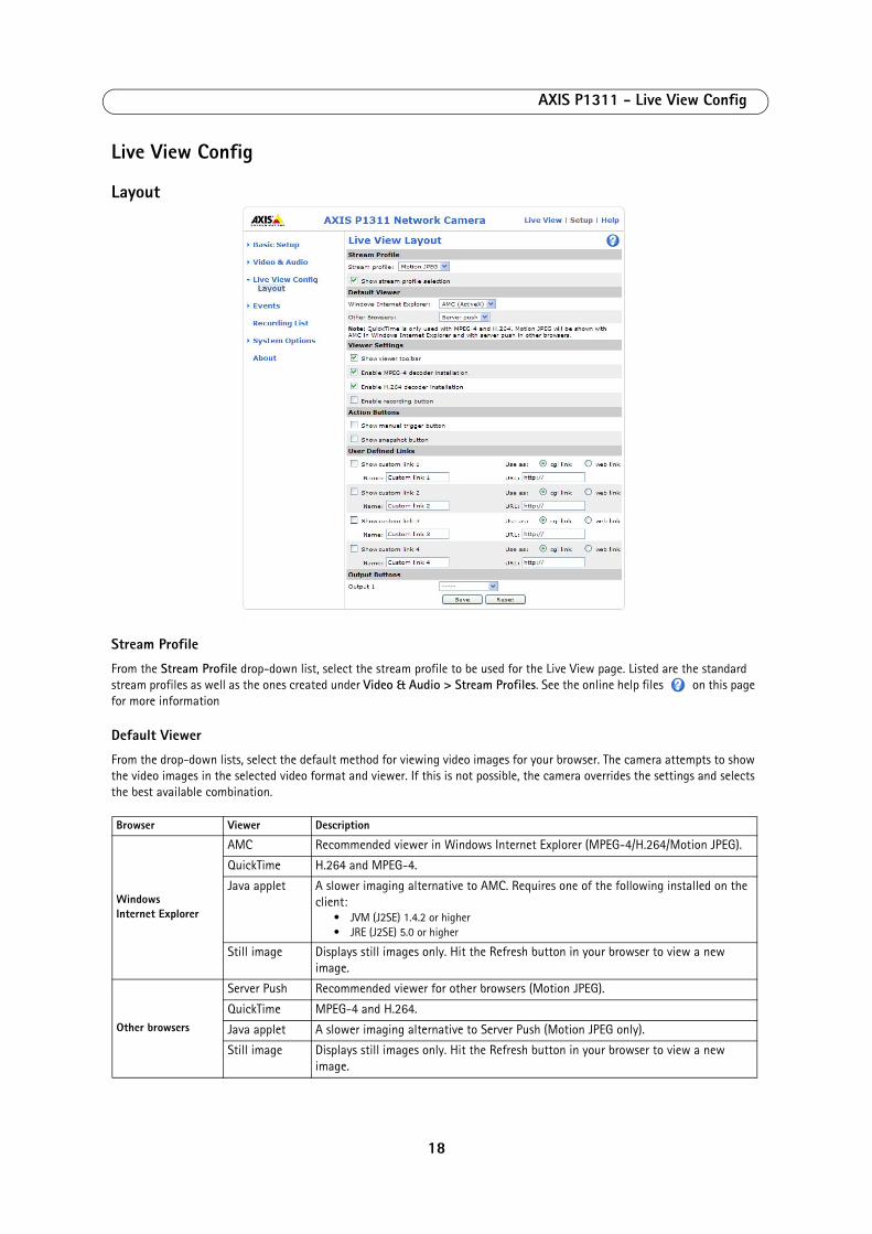
Stream Profile
From the Stream Profile drop-down list, select the stream profile to be used for the Live View page. Listed are the standard stream profiles as well as the ones created under Video & Audio > Stream Profiles. See the online help files on this page for more information
Default Viewer
From the drop-down lists, select the default method for viewing video images for your browser. The camera attempts to show the video images in the selected video format and viewer. If this is not possible, the camera overrides the settings and selects the best available combination.
Browser Viewer Description
Windows Internet Explorer
AMC Recommended viewer in Windows Internet Explorer (MPEG-4/H.264/Motion JPEG).
QuickTime H.264 and MPEG-4.
Java applet A slower imaging alternative to AMC. Requires one of the following installed on the client:
• JVM (J2SE) 1.4.2 or higher• JRE (J2SE) 5.0 or higher
Still image Displays still images only. Hit the Refresh button in your browser to view a new image.
Other browsers
Server Push Recommended viewer for other browsers (Motion JPEG).
QuickTime MPEG-4 and H.264.
Java applet A slower imaging alternative to Server Push (Motion JPEG only).
Still image Displays still images only. Hit the Refresh button in your browser to view a new image.
18
AXIS P1311 - Live View Config
Viewer Settings
Check the Show viewer toolbar box to display the AXIS Media Control (AMC) or the QuickTime viewer toolbar under the video image in your browser.
The administrator can disable the installation of the H.264, MPEG-4, and AAC decoders included with AMC. This is used to prevent the installation of unlicensed copies. Further decoder licenses can be purchased from your Axis dealer.
Check the Enable recording button to enable recording from the Live View page.
Action Buttons
The Show manual trigger button can be used to manually trigger and stop an event from the Live View page. See Events, on page 20.
Check the Show snapshot button to save a snapshot from the video stream. This button is mainly intended for use with browsers other than Internet Explorer, or when not using AXIS Media Control (AMC) to view the video stream. AMC for Internet Explorer provides its own snapshot button.
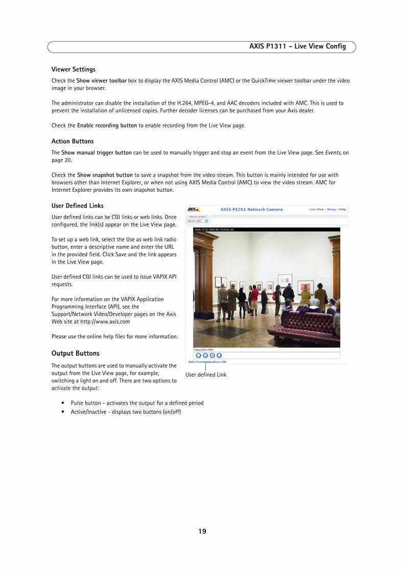
User Defined Links
User defined links can be CGI links or web links. Once configured, the link(s) appear on the Live View page.
To set up a web link, select the Use as web link radio button, enter a descriptive name and enter the URL in the provided field. Click Save and the link appears in the Live View page.
User defined CGI links can be used to issue VAPIX API requests.
For more information on the VAPIX Application Programming Interface (API), see the Support/Network Video/Developer pages on the Axis Web site at http://www.axis.com
Please use the online help files for more information.
Output Buttons
The output buttons are used to manually activate the output from the Live View page, for example, switching a light on and off. There are two options to activate the output:
• Pulse button - activates the output for a defined period• Active/Inactive - displays two buttons (on/off)
User defined Link
19
AXIS P1311 - Events
EventsPre-defined parameters, known as an event or Event Type can trigger certain actions in the camera. A common event type is an alarm that causes the camera to upload images. Many event types use an Event Server, to receive uploaded images.
An event that is triggered by a signal, such as a door switch, motion detection, or system event, is called a triggered event, see page 21.
A scheduled event runs at pre-programmed times.
An Action refers to what happens when the event occurs.
This section describes how to configure the camera to perform certain actions when events occur.
Event ServersEvent Servers are used to receive uploaded image files and/or notification messages. To set up Event Server connections in your camera, go to Setup > Events > Event Servers and enter the required information for the required server type.
For details on each setting, see the online help available from each web page.
When the setup is complete, the connection can be tested by clicking the Test button (the connection test takes approximately 10 seconds).
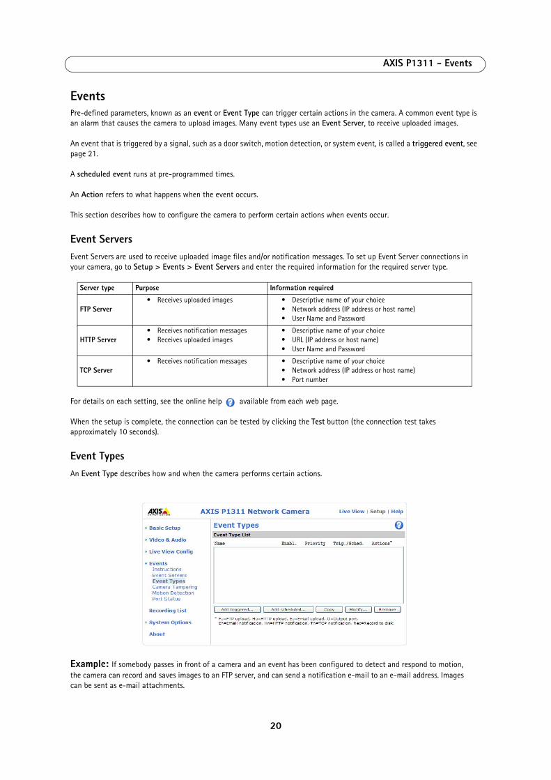
Event TypesAn Event Type describes how and when the camera performs certain actions.
Example: If somebody passes in front of a camera and an event has been configured to detect and respond to motion, the camera can record and saves images to an FTP server, and can send a notification e-mail to an e-mail address. Images can be sent as e-mail attachments.
Server type Purpose Information required
FTP Server• Receives uploaded images • Descriptive name of your choice
• Network address (IP address or host name)• User Name and Password
HTTP Server• Receives notification messages• Receives uploaded images
• Descriptive name of your choice• URL (IP address or host name)• User Name and Password
TCP Server • Receives notification messages • Descriptive name of your choice
• Network address (IP address or host name)• Port number
20
AXIS P1311 - Events
Triggered Event
A triggered event could be activated by:
• a push button connected to the camera’s input port• a manually activated action, such as from an action button in the web interface• detected movement in a configured motion detection window• sound at a certain decibel level• on restart (reboot), after power loss• camera tampering• a recording storage disk that becomes full
How to set up a triggered event
The following example describes how to set up the camera to upload images when the main door is opened.
1. Click Add triggered... on the Event Types page. The Triggered Event Type Setup page appears.2. Enter a descriptive Name for the event, such as Main door open.3. Set the Priority - High, Normal or Low (see the online help).4. Set the Respond to Trigger... parameters to define when the event is active, for example, after office hours.5. Select the trigger alternative from the Triggered by... drop-down list. For example, select Input ports, for a sensor
connected to the door.6. Set the When Triggered... parameters, that is define what the camera will do if the main door is opened; for example,
upload images to an FTP server or send an e-mail notification.7. Click OK to save the event in the Event Types list.
Please see the online help for descriptions of each available option.
Note:
Up to 10 event types can be configured in the camera, and up to three of these can be configured to upload images. File names can be formatted according to specific requirements. See File Naming & Date/Time Formats online help.
Pre-trigger and Post-trigger buffers
This function is very useful when checking to see what happened immediately before and/or after a trigger, for example, 30 seconds before and/or after a door was opened. Check the Save stream checkbox under Event Types > Add Triggered... > When Triggered... to view the options. All uploaded images are JPEG images.
Include pre-trigger buffer - images stored internally in the server from the time immediately preceding the trigger. Check the box to enable the pre-trigger buffer, enter the desired length of time and specify the required image frequency.
Include post-trigger buffer - contains images from the time immediately after the trigger. Configure as for pre-trigger.
Notes
• Pre-trigger and Post-trigger buffers will be lost if the connection to the event server fails• The maximum length of the pre-/post-buffer depends on the video image size and selected frame rate• If the pre- or post-buffer is too large for the camera’s internal memory, the frame rate is reduced and individual
images may be missing. If this occurs, an entry is created in the unit's log file
Continue image upload (unbuffered) - enables the upload of video images for a fixed length of time. Specify the length of time for the uploaded recording, in seconds, minutes or hours, or for as long as the trigger is active. Finally, set the desired image frequency to the maximum (the maximum available) or to a specified frame rate. The frame rate will be the best possible, but might not be as high as specified, especially if uploading via a slow connection.
21
AXIS P1311 - Events
Scheduled Event
A Scheduled event can be activated at preset times, in a repeating pattern on selected weekdays.
Configuration example:
1. Click Add scheduled... on the Event Types page.2. Enter a descriptive Name for the event, such as Scheduled e-mail upload.3. Set the Priority (High, Normal or Low).4. Set the Activation Time parameters (24h clock) for the event - start on Sundays at 13.00 with a duration of 12 hours.5. Set the When Activated... parameters, (what the camera would do at the specified time) for example, send uploaded
images to an e-mail address.6. Click OK to save the Event in the Event Types list.
Please see the online help for descriptions of each available option.
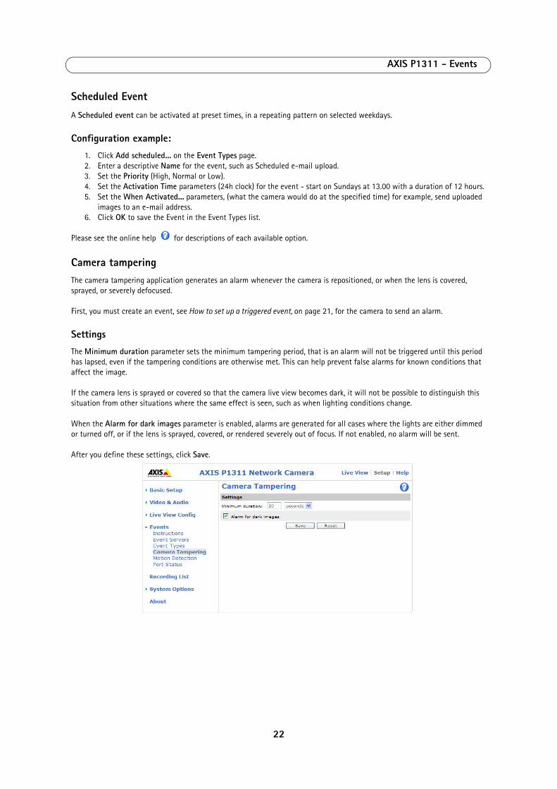
Camera tamperingThe camera tampering application generates an alarm whenever the camera is repositioned, or when the lens is covered, sprayed, or severely defocused.
First, you must create an event, see How to set up a triggered event, on page 21, for the camera to send an alarm.
Settings
The Minimum duration parameter sets the minimum tampering period, that is an alarm will not be triggered until this period has lapsed, even if the tampering conditions are otherwise met. This can help prevent false alarms for known conditions that affect the image.
If the camera lens is sprayed or covered so that the camera live view becomes dark, it will not be possible to distinguish this situation from other situations where the same effect is seen, such as when lighting conditions change.
When the Alarm for dark images parameter is enabled, alarms are generated for all cases where the lights are either dimmed or turned off, or if the lens is sprayed, covered, or rendered severely out of focus. If not enabled, no alarm will be sent.
After you define these settings, click Save.
22
AXIS P1311 - Events
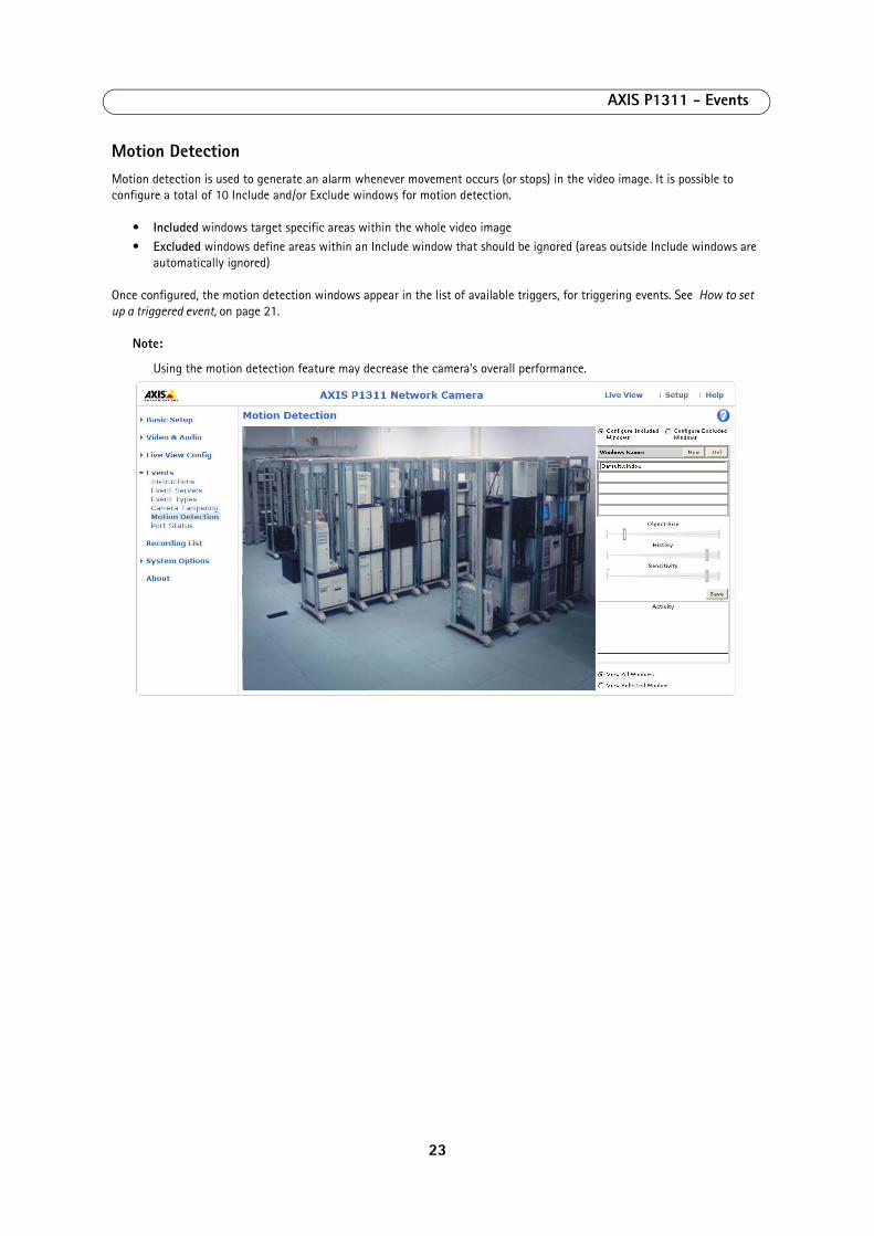
Motion DetectionMotion detection is used to generate an alarm whenever movement occurs (or stops) in the video image. It is possible to configure a total of 10 Include and/or Exclude windows for motion detection.
• Included windows target specific areas within the whole video image• Excluded windows define areas within an Include window that should be ignored (areas outside Include windows are
automatically ignored)
Once configured, the motion detection windows appear in the list of available triggers, for triggering events. See How to set up a triggered event, on page 21.
Note:
Using the motion detection feature may decrease the camera’s overall performance.
23
AXIS P1311 - Events
Configuring Motion Detection
1. Click Motion Detection in the Events menu.2. Click the New button against Windows Name.3. Select the Configure Included Windows or the Configure Excluded Windows option to define an Include or Exclude
window, and enter a descriptive name in the field below.4. Adjust the size (drag the bottom right-hand corner) and position (click on the text at the top and drag to the desired
position) of the active window.5. Adjust the Object Size, History and Sensitivity profile sliders (see table below for details). Any detected motion within
an active window is then indicated by red peaks in the Activity window (the active window has a red frame).6. Click Save.
Please see the online help for descriptions of each available option.
• Avoid triggering on small objects in the video image by setting the object size level to high.• Use several small Motion Detection windows rather than one large window, if triggers on small movements or
objects are desired.• To reduce the number of triggers if there is a lot of movement during a short period of time, select a high history
level.• To only detect flashing light, select low sensitivity. In other cases, a high sensitivity level is recommended.
Port StatusUnder Event Configuration > Port Status there is a list showing the status for the camera’s input and output. This is for the benefit of Operators who have no access to the System Options section.
Example: If the Normal state for a push button connected to an input is set to Open circuit - as long as the button is not pushed, the state is inactive. If the button is pushed, the state of the input changes to active.
To exclude parts of the Include window, select the Exclude option and position the Exclude window as required, within the Include window.
Object Size History Sensitivity
High level Only very large objects trigger motion detec-tion
An object that appears in the region will trigger the motion detection for a long period
Ordinary colored objects on ordinary backgrounds will trigger the motion detection
Low level Even very small objects trigger motion detec-tion
An object that appears in the region will trigger motion detection for only a very short period
Only very bright objects on a dark background trigger motion detection
Default value Low High High
24
AXIS P1311 - Recording List
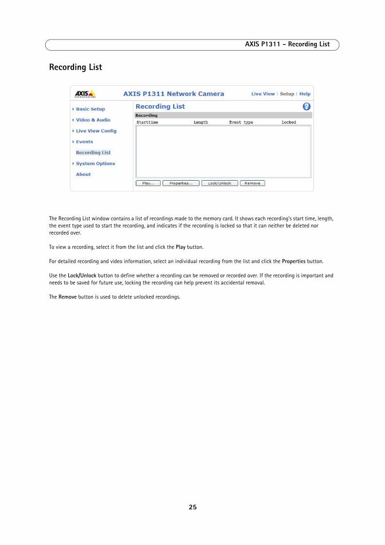
Recording List
The Recording List window contains a list of recordings made to the memory card. It shows each recording's start time, length, the event type used to start the recording, and indicates if the recording is locked so that it can neither be deleted nor recorded over.
To view a recording, select it from the list and click the Play button.
For detailed recording and video information, select an individual recording from the list and click the Properties button.
Use the Lock/Unlock button to define whether a recording can be removed or recorded over. If the recording is important and needs to be saved for future use, locking the recording can help prevent its accidental removal.
The Remove button is used to delete unlocked recordings.
25
AXIS P1311 - System Options
System Options
Security
Users
User access control is enabled by default. An administrator can set up other users, by giving them user names and passwords. It is also possible to allow anonymous viewer login, which means that anybody may access the Live View page, as described below:
The user list displays the authorized users and user groups (levels):
HTTP/RTSP Password Settings - Select the type of password. You may need to allow unencrypted passwords if there are viewing clients that do not support encryption, or if you recently upgraded the firmware and the existing clients support encryption, but need to log in again, and be configured to use this functionality.
User Settings - Check the relevant box to enable anonymous viewer login - allows any viewer direct access to the Live View page.
Enable Basic Setup - Before using AXIS P1311, there are certain settings that should be made, most of which require Administrator access privileges. To quickly access these settings use the Basic Setup in the menu. All settings are also available from the standard setup links in the menu. Basic Setup is enabled by default but can be disabled and removed from the menu.
IP Address Filter
Enable IP Address Filtering to allow or deny access to the network cameras. Once enabled, the IP addresses in the list are allowed or denied access according to the choice made in the drop-down list Allow/Deny the following IP addresses.
The administrator can add up to 256 IP address entries to the list (a single entry can contain multiple IP addresses). The users from these IP addresses need to be specified in the user list with the appropriate access rights. This is done from Setup > System Options > Security > Users.
HTTPS
The network camera supports encrypted browsing using HTTPS.
A self-signed certificate can be used until a Certificate Authority-issued certificate has been obtained. Click the Create self-signed Certificate button to install a self-signed certificate. Although self-signed certificates are free and offer some protection, true security is only implemented after the installation of a signed certificate issued by a certificate authority.
A signed certificate can be obtained from an issuing Certificate Authority by clicking the Create Certificate Request button. When the signed certificate is returned, click the Install signed certificate button to import the certificate. The properties of any certificate request currently resident in the camera or installed can also be viewed by clicking the Properties... button. The HTTPS Connection Policy must also be set in the drop-down lists to enable HTTPS in the camera.
For more information, please refer to the online help .
Viewer Provides the lowest level of access, which only allows access to the Live View page.
Operator An operator can view the Live View page, create and modify events, and adjust certain other settings. Operators have no access to System Options.
Administrator An administrator has unrestricted access to all menus for configuration and can determine the registration of all other users.
26
AXIS P1311 - System Options
IEEE 802.1X
IEEE 802.1X is a standard for port-based Network Admission Control providing secure authentication of wired and wireless network devices. IEEE 802.1X is based on EAP (Extensible Authentication Protocol).
To access a network protected by IEEE 802.1X, devices must authenticate themselves. The authentication is performed by a third-party entity called an authentication server, typically a RADIUS server, examples of which are FreeRADIUS and Microsoft Internet Authentication Service. In Axis implementation, the network device and authentication server authenticate themselves with the help of digital certificates using EAP-TLS (Extensible Authentication Protocol - Transport Layer Security). The certificates are provided by an Certification Authority (CA). You need:
• a CA certificate to validate the identity of the authentication server
• a CA-signed client certificate and a private key to authenticate the network device
To allow the network device to access a private network protected by IEEE 802.1X:
1. Obtain a CA certificate, a client certificate and a client private key (contact your network administrator).2. Go to Setup > System Options > Security > IEEE 802.1X and upload the CA certificate, the client certificate and the
private key.3. Under Settings, select the EAPOL version, provide your EAP identity and private key password.4. Check the box to enable IEEE 802.1X and click Save.
Certificates
CA Certificate - The CA certificate is used to validate the identity of the authentication server. Enter the path to the certificate directly, or locate the file using the Browse button. Then click Upload. To remove a certificate, click Remove.
Client certificate/Client private key - The client certificate and private key are used to authenticate the network device. They can be uploaded as separate files or in one combined file (e.g. a PFX file or a PEM file). Use the Client private key field if uploading one combined file. For each file, enter the path to the certificate directly, or locate the file using the Browse button. Then click Upload. To remove a certificate, click Remove.
Settings
EAPOL version - Select the EAPOL version (1 or 2) as used in your network switch.
EAP identity - Enter the user identity (maximum 16 characters) associated with your certificate.
Private key password - Enter the password (maximum 16 characters) for the private key.
Enable 802.1X - Check the box to enable the 802.1X protocol.
Audio Support
Enable audio support - This option allows clients to retrieve audio streams from the AXIS P1311. See also Audio Settings, on page 16 for information on how to configure the audio settings.
Note:
This parameter will enable/disable audio globally in the camera, even for configured events and profiles with audio.
Date & Time
Current Server Time - Displays the current date and time (24h clock). The time can be displayed in 12h clock format in the overlay (see below).
New Server Time - Select your time zone from the drop-down list. If you want the server clock to automatically adjust for daylight savings time, select the Automatically adjust for daylight saving time changes option.
27
AXIS P1311 - System Options
From the Time Mode section, select the preferred method to use for setting the time:
• Synchronize with computer time - sets the time from the clock on your computer. • Synchronize with NTP Server - the camera will obtain the time from an NTP server every 60 minutes.• Set manually - this option allows you to manually set the time and date.
Note:
If using a host name for the NTP server, a DNS server must be configured under TCP/IP settings. See Network > Basic TCP/IP Settings below.
Date & Time Format Used in Images - Specify the formats for the date and time (12h or 24h) displayed in the video streams.
Use the predefined formats or use your own custom date and time formats. See Advanced File Naming & Date/Time Formats in the online help for information on how to create your own date and time formats.
Network
Basic TCP/IP Settings
AXIS P1311 support both IP version 4 and IP version 6. Both versions may be enabled simultaneously, and at least one version must always be enabled. When using IPv4, the IP address for the camera can be set automatically via DHCP, or a static IP address can be set manually. If IPv6 is enabled, the network cameras receive an IP address according to the configuration in the network router. There are also options for setting up notification of changes in the IP address, and for using the AXIS Internet Dynamic DNS Service. For more information on setting the IP address, please see the online help.
Network Settings - Click View for an overview of the IP configuration of the network camera.
IPv4 Address Configuration - Check the Enable IPv4 box option to enable IPv4.
Obtain IP address via DHCP - Dynamic Host Configuration Protocol (DHCP) is a protocol that lets network administrators centrally manage and automate the assignment of IP addresses on a network. DHCP is enabled by default. Although a DHCP server is mostly used to set an IP address dynamically, it is also possible to use it to set a static, known IP address for a particular MAC address.
Note:
DHCP should only be enabled if your DHCP server can update a DNS server, which then allows you to access AXIS P1311 by name (host name). If DHCP is enabled and you cannot access the unit, run AXIS IP Utility to search the net-work for connected Axis products or reset the network camera to factory default settings and then perform the instal-lation again.
Use the following IP address - To use a static IP address for the AXIS P1311 Network Camera, check the radio button and then make the following settings:
• IP address - Specify a unique IP address for your AXIS P1311 Network Camera. (To check if the IP address you intend to use is available or not, click the Test button)
• Subnet mask - Specify the mask for the subnet the AXIS P1311 Network Camera is located on
• Default router - Specify the IP address of the default router (gateway) used for connecting devices attached to differ-ent networks and network segments.
IPv6 Address Configuration - Check the Enable IPv6 box option to enable IPv6. Other settings for IPv6 are configured in the network router.
Services - Enable ARP/Ping setting of IP address - The IP address can be set using the ARP/Ping method, which associates the unit's MAC address with an IP address. Check this box to enable the service. Leave disabled to prevent unintentional resetting of the IP address.
28
AXIS P1311 - System Options
Notes: • The ARP/Ping service is automatically disabled two minutes after the unit is started, or as soon as an IP address is
set. In order to reset the IP address, the camera must be restarted to activate ARP/Ping for an additional two minutes.
• Pinging the unit is still possible when this service is disabled.
AXIS Internet Dynamic DNS Service - Use AXIS Internet Dynamic DNS Service to assign a host name for easy access to your network camera (requires Internet access).
Click Settings... to register the camera with AXIS Internet Dynamic DNS Service, or to modify the existing settings (requires access to the Internet). The domain name currently registered at AXIS Internet Dynamic DNS Service for your product can at any time be removed.
For more information, please refer to the online help.
Advanced TCP/IP Settings
DNS Configuration - DNS (Domain Name Service) provides the translation of host names to IP addresses on your network.
Obtain DNS server address via DHCP - Automatically use the DNS server settings provided by the DHCP server. Click the View button to see the current settings.
Use the following DNS server address - Enter the desired DNS server by specifying the following:
Domain name - Enter the domain(s) to search for the host name used by the network cameras. Multiple domains can be separated by semicolons (;). The host name is always the first part of a Fully Qualified Domain Name, for example, myserver is the host name in the Fully Qualified Domain Name myserver.mycompany.com where mycompany.com is the Domain name.
Primary and Secondary DNS servers - Enter the IP addresses of the primary, and secondary DNS servers.
Note:
This is not mandatory with regard to secondary DNS servers.
NTP Configuration - Obtain NTP server address via DHCP - Check this radio button to automatically look up and use the NTP server settings as provided by DHCP. Click the View button to see the current settings.
Use the following NTP server address - To create manual settings, check this radio button and enter the host name or IP address of the NTP server.
Host Name Configuration - The network camera can be accessed using a host name, instead of an IP address. The host name is usually the same as the assigned DNS Name.
For more information, please see Security, on page 26.
Link-Local IPv4 Address - This is enabled by default and assigns the network cameras an additional IP address for use with UPnP™ . The camera can have both a Link-Local IP and a static/DHCP-supplied IP address at the same time - these will not affect each other.
HTTP and HTTPS - The default HTTP/HTTPS port numbers (80 and 443 respectively) can be changed to any port within the range 1024-65535. This is useful for simple security port mapping, for example.
NAT traversal (port mapping) for IPv4 - A broadband router allows devices on a private network (LAN) to share a single connection to the Internet. This is done by forwarding network traffic from the private network to the “outside”, that is, the Internet. Security on the private network (LAN) is increased since most broadband routers are pre-configured to stop attempts to access the private network (LAN) from the public network/Internet.
29
AXIS P1311 - System Options
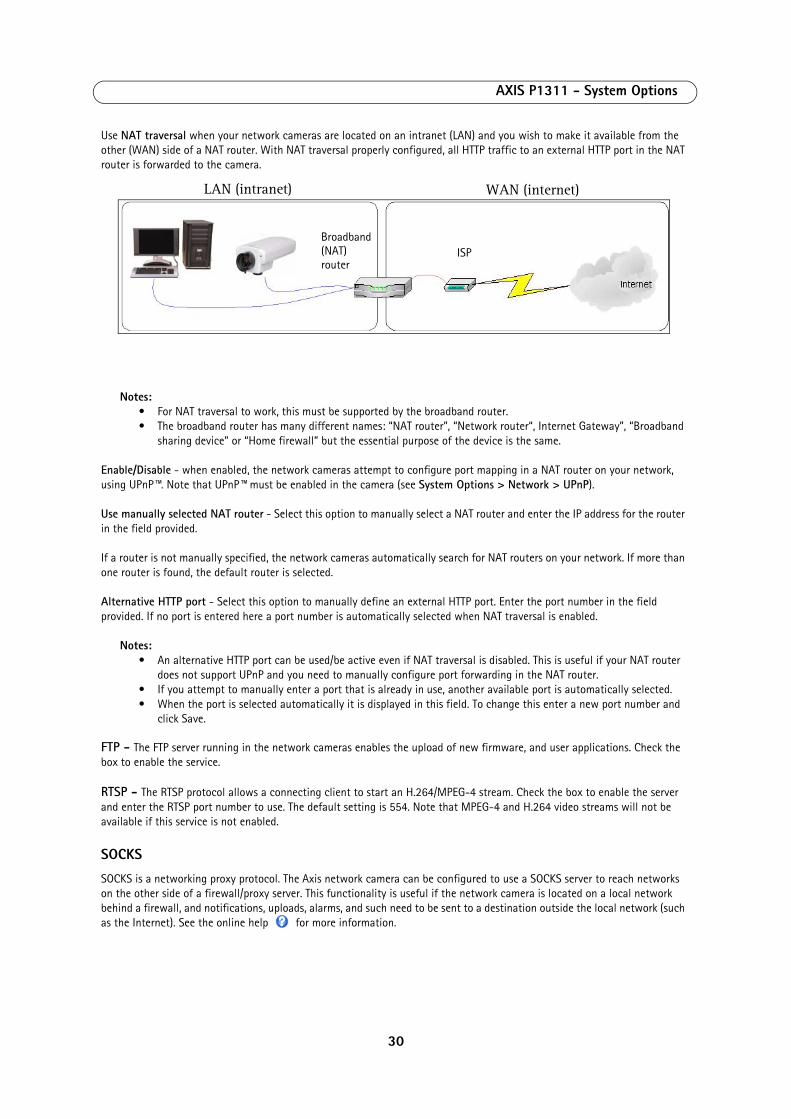
Use NAT traversal when your network cameras are located on an intranet (LAN) and you wish to make it available from the other (WAN) side of a NAT router. With NAT traversal properly configured, all HTTP traffic to an external HTTP port in the NAT router is forwarded to the camera.
Notes: • For NAT traversal to work, this must be supported by the broadband router.
• The broadband router has many different names: “NAT router”, “Network router“, Internet Gateway”, “Broadband sharing device” or “Home firewall” but the essential purpose of the device is the same.
Enable/Disable - when enabled, the network cameras attempt to configure port mapping in a NAT router on your network, using UPnP™. Note that UPnP™ must be enabled in the camera (see System Options > Network > UPnP).
Use manually selected NAT router - Select this option to manually select a NAT router and enter the IP address for the router in the field provided.
If a router is not manually specified, the network cameras automatically search for NAT routers on your network. If more than one router is found, the default router is selected.
Alternative HTTP port - Select this option to manually define an external HTTP port. Enter the port number in the field provided. If no port is entered here a port number is automatically selected when NAT traversal is enabled.
Notes: • An alternative HTTP port can be used/be active even if NAT traversal is disabled. This is useful if your NAT router
does not support UPnP and you need to manually configure port forwarding in the NAT router.• If you attempt to manually enter a port that is already in use, another available port is automatically selected.• When the port is selected automatically it is displayed in this field. To change this enter a new port number and
click Save.
FTP - The FTP server running in the network cameras enables the upload of new firmware, and user applications. Check the box to enable the service.
RTSP - The RTSP protocol allows a connecting client to start an H.264/MPEG-4 stream. Check the box to enable the server and enter the RTSP port number to use. The default setting is 554. Note that MPEG-4 and H.264 video streams will not be available if this service is not enabled.
SOCKS
SOCKS is a networking proxy protocol. The Axis network camera can be configured to use a SOCKS server to reach networks on the other side of a firewall/proxy server. This functionality is useful if the network camera is located on a local network behind a firewall, and notifications, uploads, alarms, and such need to be sent to a destination outside the local network (such as the Internet). See the online help for more information.
LAN (intranet) WAN (internet)
Broadband (NAT)router
ISP
30
AXIS P1311 - System Options
QoS (Quality of Service)
Quality of Service (QoS) guarantees a certain level of a specified resource to selected traffic on a network. Quality can be defined as a maintained level of bandwidth, low latency, and no packet losses. The main benefits of a QoS-aware network can be summarized as:
• The ability to prioritize traffic and thus allow critical flows to be served before flows with lesser priority.
• Greater reliability in the network, thanks to the control of the amount of bandwidth an application may use, and thus control over bandwidth races between applications.
The QoS in Axis network video products marks the data packets for various types of network traffic originating from the product. This makes it possible for network routers and switches to reserve a fixed amount of bandwidth for these types of traffic. The network cameras mark the following types of traffic:
• video
• audio
• event/alarm
• management network traffic
QoS Settings - For each type of network traffic supported by your Axis network video product, enter a DSCP (Differentiated Services Codepoint) value. This value is used to mark the traffic’s IP header. When the marked traffic reaches a network router or switch, the DSCP value in the IP header tells the router or switch the type of treatment to apply to this type of traffic, for example, how much bandwidth to reserve for it. Note that DSCP values can be entered in decimal or hex form, but saved values are always shown in decimal.
For more information on Quality of Service, please see the Axis support web at www.axis.com/techsup
SMTP (email)
Enter the host names (or IP addresses) and port numbers for your primary and secondary mail servers in the fields provided, to enable the sending of notifications and image email messages from the camera to predefined addresses via SMTP.
If your mail server requires authentication, check the box for Use authentication to log in to this server and enter the necessary information. See the online help for more information.
SNMP
The Simple Network Management Protocol (SNMP) allows remote management of network devices. An SNMP community is the group of devices and management station running SNMP. Community names are used to identify groups.
Depending on the level of security required, select the version of SNMP to use. The three levels of security are:
SNMP v1/v2Select either SNMP V1 that includes no security, or SNMP V2c that uses very simple security.
The community name can be specified as a password for read or read/write access to all supported SNMP objects. The community is the group of network devices using SNMP. The default password for the Read Community is public and the default password for the Write community is write.
Traps for SNMP v1/v2Traps are used by the camera to send messages to a management system for important events or status changes.
If Enable traps is selected, enter the email address where the trap message is to be sent as well as the Trap community that should receive the message.
31
AXIS P1311 - System Options
There are four types of traps available for the AXIS P1311.
• Cold start
• Warm start
• Link up
• Authentication failed
SNMP v3SNMP V3 - provides encryption and secure passwords. HTTPS must be enabled. To use traps with SNMP v3 an SNMP v3 management application is required.
If the Enable SNMP v3 option is enabled, provide the Initial user password. Note that the initial password is activated only when HTTPS is enabled and can only be set once.
If HTTPS is enabled, SNMP v1 and SNMP v2c should be disabled.
When SNMP configuration is ready, click Save to use the new settings or Reset to return to the default values.
UPnP™
The network camera includes support for UPnP™. UPnP™ is enabled by default, and the network camera then is automatically detected by operating systems and clients that support this protocol.
RTP
RTP/ MPEG-4 & H.264 - These settings are the port range, IP address, port number (video and audio), and Time-To-Live value to use for the video stream(s) in multicast MPEG-4 and H.264 format. Only certain IP addresses and port numbers should be used for multicast streams. For more information, please see the online help.
Bonjour
The network cameras include support for Bonjour. When enabled, the camera is automatically detected by operating systems and clients that support this.
StorageThe Disk Management window is used to set up and manage local storage. It is used to connect memory cards for recording video, monitoring a disk's status, enabling automatic cleanup, and preventing a memory card's memory from being overwritten.
Storage Device - is used to identify and monitor the status of the SD card. It shows the size of the SD card and how free space is available for storage. It is also used to mount and format SD cards for local storage.
Device Settings - is used to configure removal of recorded video. Automatic disk cleanup can be enabled and set up according to a schedule, and an SD card can be locked to prevent storage removal.
Ports & Devices
I/O Ports - The pinout, interface support and the control and monitoring functions provided by this connector are described in Unit connectors, on page 36.
LEDThe Status indicator LED on the front of the camera can be set to flash at a configurable interval (or to not light up at all) when the unit is accessed. For a listing of all LED behavior, see page 5, or the online help. Note that the LED does not flash when the stream is retrieved using multicast.
32
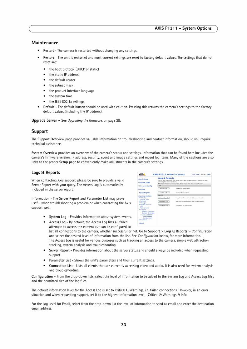
AXIS P1311 - System Options
Maintenance• Restart - The camera is restarted without changing any settings.
• Restore - The unit is restarted and most current settings are reset to factory default values. The settings that do not reset are:
• the boot protocol (DHCP or static)• the static IP address• the default router• the subnet mask• the product interface language• the system time• the IEEE 802.1x settings
• Default - The default button should be used with caution. Pressing this returns the camera's settings to the factory default values (including the IP address).
Upgrade Server - See Upgrading the firmware, on page 38.
SupportThe Support Overview page provides valuable information on troubleshooting and contact information, should you require technical assistance.
System Overview provides an overview of the camera’s status and settings. Information that can be found here includes the camera’s firmware version, IP address, security, event and image settings and recent log items. Many of the captions are also links to the proper Setup page to conveniently make adjustments in the camera’s settings.
Logs & Reports
When contacting Axis support, please be sure to provide a valid Server Report with your query. The Access Log is automatically included in the server report.
Information - The Server Report and Parameter List may prove useful when troubleshooting a problem or when contacting the Axis support web.
• System Log - Provides information about system events.• Access Log - By default, the Access Log lists all failed
attempts to access the camera but can be configured to list all connections to the camera, whether successful or not. Go to Support > Logs & Reports > Configuration and select the desired level of information from the list. See Configuration, below, for more information. The Access Log is useful for various purposes such as tracking all access to the camera, simple web attraction tracking, system analysis and troubleshooting.
• Server Report - Provides information about the server status and should always be included when requesting support.
• Parameter List - Shows the unit's parameters and their current settings.• Connection List - Lists all clients that are currently accessing video and audio. It is also used for system analysis
and troubleshooting.
Configuration - From the drop-down lists, select the level of information to be added to the System Log and Access Log files and the permitted size of the log files.
The default information level for the Access Log is set to Critical & Warnings, i.e. failed connections. However, in an error situation and when requesting support, set it to the highest information level - Critical & Warnings & Info.
For the Log Level for Email, select from the drop-down list the level of information to send as email and enter the destination email address.
33
AXIS P1311 - System Options
AdvancedScripting is an advanced function that enables you to customize and use scripts. This function is a very powerful tool.
Caution!Improper use may cause unexpected behavior or even cause loss of contact with the unit. If a script does cause problems, reset the unit to its factory default settings. A backup file may be of use to return the unit to its latest configuration. Axis recommends that you do not use this function unless you understand the consequences. Note that Axis support does not provide assistance for problems with customized scripts.
For more information, please visit the Developer pages at www.axis.com/developer
File Upload - To use your own files as custom settings, upload the files first to the AXIS P1311 Network Camera. Browse to select the file. Select the User level for the uploaded file. When the file is displayed correctly in the text field, click the Upload button.
Plain Config - this function is for the advanced user with experience of Axis network camera configuration. All parameters can be set and modified from this page. Help is available from the standard help pages.
34
AXIS P1311 - About
AboutHere you can find basic information about your network camera. You can also view third party software licenses.
Resetting to Factory Default SettingsTo reset the camera to the original factory default settings, go to the System Options > Maintenance web page (as described in Maintenance, on page 33) or use the Control button on the side of the camera (see page 4) as described below:
Using the Control Button
To reset the camera to the factory default settings using the Control Button:
1. Disconnect power from the camera.2. Press and hold the Control button and reconnect power.3. Keep the Control button pressed until the Status indicator color changes to amber (this may take up to 15 seconds).4. Release the Control button.5. When the Status indicator changes to green (which may take up to 1 minute), the process is complete and the camera
has been reset. The unit now has the default IP address 192.168.0.90
Note:
For other methods of setting the IP address, please refer to the product’s Installation Guide that accompanies the product, or download a copy from www.axis.com
35
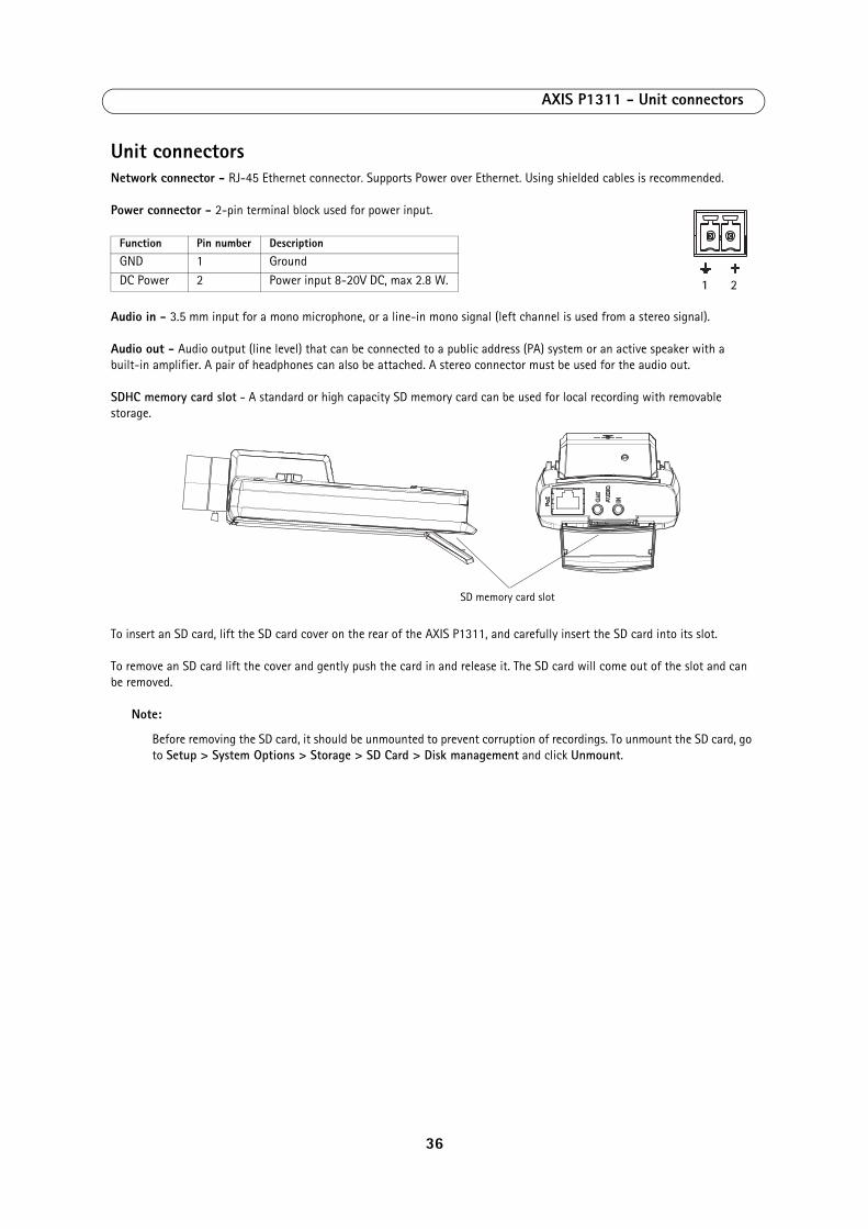
AXIS P1311 - Unit connectors
Unit connectorsNetwork connector - RJ-45 Ethernet connector. Supports Power over Ethernet. Using shielded cables is recommended.
Power connector - 2-pin terminal block used for power input.
Audio in - 3.5 mm input for a mono microphone, or a line-in mono signal (left channel is used from a stereo signal).
Audio out - Audio output (line level) that can be connected to a public address (PA) system or an active speaker with a built-in amplifier. A pair of headphones can also be attached. A stereo connector must be used for the audio out.
SDHC memory card slot - A standard or high capacity SD memory card can be used for local recording with removable storage.
To insert an SD card, lift the SD card cover on the rear of the AXIS P1311, and carefully insert the SD card into its slot.
To remove an SD card lift the cover and gently push the card in and release it. The SD card will come out of the slot and can be removed.
Note:
Before removing the SD card, it should be unmounted to prevent corruption of recordings. To unmount the SD card, go to Setup > System Options > Storage > SD Card > Disk management and click Unmount.
Function Pin number Description
GND 1 GroundDC Power 2 Power input 8-20V DC, max 2.8 W. 1 2
SD memory card slot
36
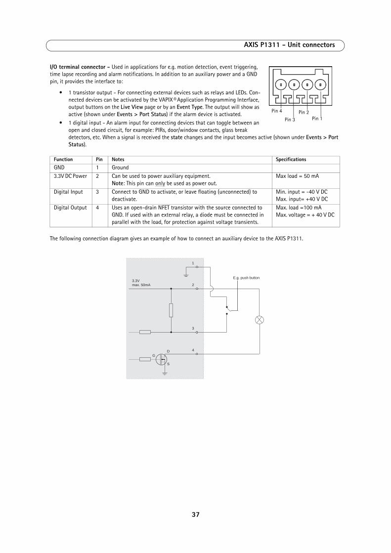
AXIS P1311 - Unit connectors
I/O terminal connector - Used in applications for e.g. motion detection, event triggering, time lapse recording and alarm notifications. In addition to an auxiliary power and a GND pin, it provides the interface to:
• 1 transistor output - For connecting external devices such as relays and LEDs. Con-nected devices can be activated by the VAPIX® Application Programming Interface, output buttons on the Live View page or by an Event Type. The output will show as active (shown under Events > Port Status) if the alarm device is activated.
• 1 digital input - An alarm input for connecting devices that can toggle between an open and closed circuit, for example: PIRs, door/window contacts, glass break detectors, etc. When a signal is received the state changes and the input becomes active (shown under Events > Port Status).
The following connection diagram gives an example of how to connect an auxiliary device to the AXIS P1311.
Function Pin Notes Specifications
GND 1 Ground3.3V DC Power 2 Can be used to power auxiliary equipment.
Note: This pin can only be used as power out.Max load = 50 mA
Digital Input 3 Connect to GND to activate, or leave floating (unconnected) to deactivate.
Min. input = -40 V DC Max. input= +40 V DC
Digital Output 4 Uses an open-drain NFET transistor with the source connected to GND. If used with an external relay, a diode must be connected in parallel with the load, for protection against voltage transients.
Max. load =100 mA Max. voltage = + 40 V DC
Pin 3
Pin 4 Pin 2Pin 1
1
2
E.g. push button
3
4
3.3Vmax. 50mA
D
S
G
37
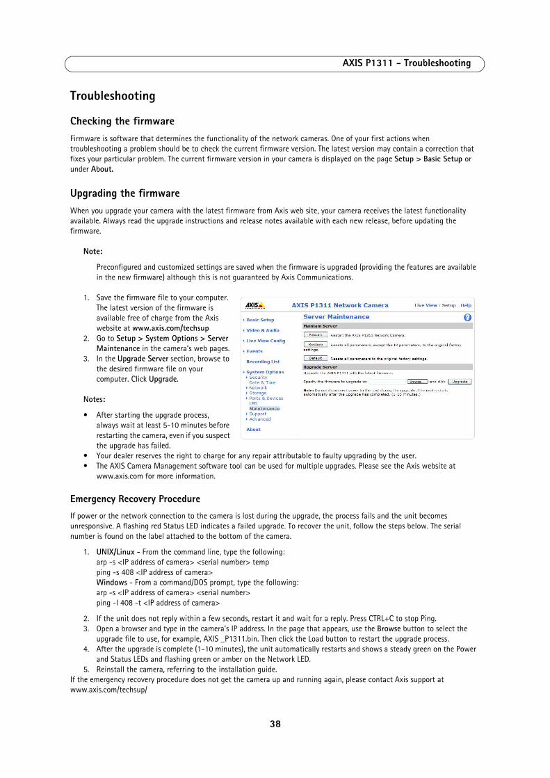
AXIS P1311 - Troubleshooting
Troubleshooting
Checking the firmwareFirmware is software that determines the functionality of the network cameras. One of your first actions when troubleshooting a problem should be to check the current firmware version. The latest version may contain a correction that fixes your particular problem. The current firmware version in your camera is displayed on the page Setup > Basic Setup or under About.
Upgrading the firmwareWhen you upgrade your camera with the latest firmware from Axis web site, your camera receives the latest functionality available. Always read the upgrade instructions and release notes available with each new release, before updating the firmware.
Note:
Preconfigured and customized settings are saved when the firmware is upgraded (providing the features are available in the new firmware) although this is not guaranteed by Axis Communications.
1. Save the firmware file to your computer. The latest version of the firmware is available free of charge from the Axis website at www.axis.com/techsup
2. Go to Setup > System Options > Server Maintenance in the camera’s web pages.
3. In the Upgrade Server section, browse to the desired firmware file on your computer. Click Upgrade.
Notes:
• After starting the upgrade process, always wait at least 5-10 minutes before restarting the camera, even if you suspect the upgrade has failed.
• Your dealer reserves the right to charge for any repair attributable to faulty upgrading by the user.• The AXIS Camera Management software tool can be used for multiple upgrades. Please see the Axis website at
www.axis.com for more information.
Emergency Recovery Procedure
If power or the network connection to the camera is lost during the upgrade, the process fails and the unit becomes unresponsive. A flashing red Status LED indicates a failed upgrade. To recover the unit, follow the steps below. The serial number is found on the label attached to the bottom of the camera.
1. UNIX/Linux - From the command line, type the following: arp -s <IP address of camera> <serial number> temp ping -s 408 <IP address of camera> Windows - From a command/DOS prompt, type the following: arp -s <IP address of camera> <serial number> ping -l 408 -t <IP address of camera>
2. If the unit does not reply within a few seconds, restart it and wait for a reply. Press CTRL+C to stop Ping.3. Open a browser and type in the camera’s IP address. In the page that appears, use the Browse button to select the
upgrade file to use, for example, AXIS _P1311.bin. Then click the Load button to restart the upgrade process. 4. After the upgrade is complete (1-10 minutes), the unit automatically restarts and shows a steady green on the Power
and Status LEDs and flashing green or amber on the Network LED. 5. Reinstall the camera, referring to the installation guide.
If the emergency recovery procedure does not get the camera up and running again, please contact Axis support at www.axis.com/techsup/
38

AXIS P1311 - Troubleshooting
Axis Support
If you contact Axis support, please help us resolve your problem expediently by providing a Server Report and a detailed description of the problem.
The Server Report contains important information about the server and its software, as well as a list of the current parameters. The Access Log is also included in the Server Report. Go to Setup > System Options > Support > Support Overview to generate a Server Report.
39
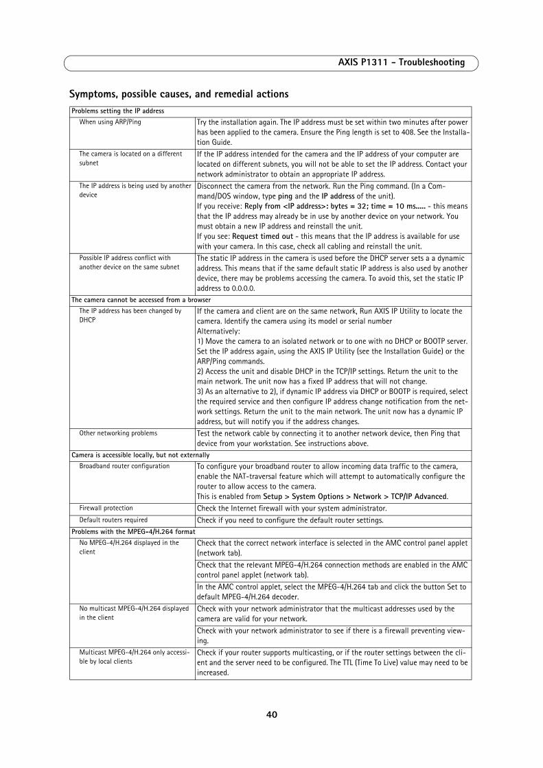
AXIS P1311 - Troubleshooting
Symptoms, possible causes, and remedial actionsProblems setting the IP address
When using ARP/Ping Try the installation again. The IP address must be set within two minutes after power has been applied to the camera. Ensure the Ping length is set to 408. See the Installa-tion Guide.
The camera is located on a different subnet
If the IP address intended for the camera and the IP address of your computer are located on different subnets, you will not be able to set the IP address. Contact your network administrator to obtain an appropriate IP address.
The IP address is being used by another device
Disconnect the camera from the network. Run the Ping command. (In a Com-mand/DOS window, type ping and the IP address of the unit). If you receive: Reply from <IP address>: bytes = 32; time = 10 ms..... - this means that the IP address may already be in use by another device on your network. You must obtain a new IP address and reinstall the unit. If you see: Request timed out - this means that the IP address is available for use with your camera. In this case, check all cabling and reinstall the unit.
Possible IP address conflict with another device on the same subnet
The static IP address in the camera is used before the DHCP server sets a a dynamic address. This means that if the same default static IP address is also used by another device, there may be problems accessing the camera. To avoid this, set the static IP address to 0.0.0.0.
The camera cannot be accessed from a browserThe IP address has been changed by DHCP
If the camera and client are on the same network, Run AXIS IP Utility to locate the camera. Identify the camera using its model or serial numberAlternatively: 1) Move the camera to an isolated network or to one with no DHCP or BOOTP server. Set the IP address again, using the AXIS IP Utility (see the Installation Guide) or the ARP/Ping commands. 2) Access the unit and disable DHCP in the TCP/IP settings. Return the unit to the main network. The unit now has a fixed IP address that will not change. 3) As an alternative to 2), if dynamic IP address via DHCP or BOOTP is required, select the required service and then configure IP address change notification from the net-work settings. Return the unit to the main network. The unit now has a dynamic IP address, but will notify you if the address changes.
Other networking problems Test the network cable by connecting it to another network device, then Ping that device from your workstation. See instructions above.
Camera is accessible locally, but not externallyBroadband router configuration To configure your broadband router to allow incoming data traffic to the camera,
enable the NAT-traversal feature which will attempt to automatically configure the router to allow access to the camera. This is enabled from Setup > System Options > Network > TCP/IP Advanced.
Firewall protection Check the Internet firewall with your system administrator.Default routers required Check if you need to configure the default router settings.
Problems with the MPEG-4/H.264 formatNo MPEG-4/H.264 displayed in the client
Check that the correct network interface is selected in the AMC control panel applet (network tab). Check that the relevant MPEG-4/H.264 connection methods are enabled in the AMC control panel applet (network tab). In the AMC control applet, select the MPEG-4/H.264 tab and click the button Set to default MPEG-4/H.264 decoder.
No multicast MPEG-4/H.264 displayed in the client
Check with your network administrator that the multicast addresses used by the camera are valid for your network.Check with your network administrator to see if there is a firewall preventing view-ing.
Multicast MPEG-4/H.264 only accessi-ble by local clients
Check if your router supports multicasting, or if the router settings between the cli-ent and the server need to be configured. The TTL (Time To Live) value may need to be increased.
40
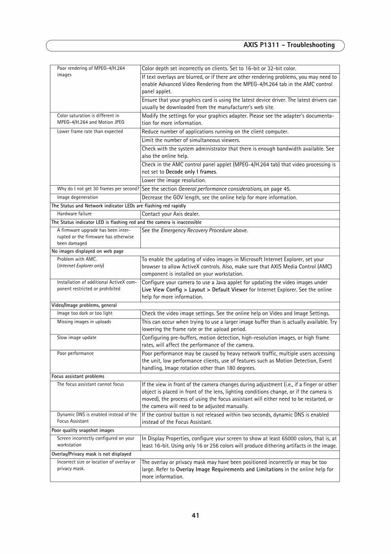
AXIS P1311 - Troubleshooting
Poor rendering of MPEG-4/H.264 images
Color depth set incorrectly on clients. Set to 16-bit or 32-bit color.If text overlays are blurred, or if there are other rendering problems, you may need to enable Advanced Video Rendering from the MPEG-4/H.264 tab in the AMC control panel applet.Ensure that your graphics card is using the latest device driver. The latest drivers can usually be downloaded from the manufacturer's web site.
Color saturation is different in MPEG-4/H.264 and Motion JPEG
Modify the settings for your graphics adapter. Please see the adapter's documenta-tion for more information.
Lower frame rate than expected Reduce number of applications running on the client computer.Limit the number of simultaneous viewers. Check with the system administrator that there is enough bandwidth available. See also the online help.Check in the AMC control panel applet (MPEG-4/H.264 tab) that video processing is not set to Decode only I frames.Lower the image resolution.
Why do I not get 30 frames per second? See the section General performance considerations, on page 45.Image degeneration Decrease the GOV length, see the online help for more information.
The Status and Network indicator LEDs are flashing red rapidlyHardware failure Contact your Axis dealer.
The Status indicator LED is flashing red and the camera is inaccessibleA firmware upgrade has been inter-rupted or the firmware has otherwise been damaged
See the Emergency Recovery Procedure above.
No images displayed on web pageProblem with AMC. (Internet Explorer only)
To enable the updating of video images in Microsoft Internet Explorer, set your browser to allow ActiveX controls. Also, make sure that AXIS Media Control (AMC) component is installed on your workstation.
Installation of additional ActiveX com-ponent restricted or prohibited
Configure your camera to use a Java applet for updating the video images under Live View Config > Layout > Default Viewer for Internet Explorer. See the online help for more information.
Video/Image problems, generalImage too dark or too light Check the video image settings. See the online help on Video and Image Settings.Missing images in uploads This can occur when trying to use a larger image buffer than is actually available. Try
lowering the frame rate or the upload period.Slow image update Configuring pre-buffers, motion detection, high-resolution images, or high frame
rates, will affect the performance of the camera. Poor performance Poor performance may be caused by heavy network traffic, multiple users accessing
the unit, low performance clients, use of features such as Motion Detection, Event handling, Image rotation other than 180 degrees.
Focus assistant problemsThe focus assistant cannot focus If the view in front of the camera changes during adjustment (i.e., if a finger or other
object is placed in front of the lens, lighting conditions change, or if the camera is moved), the process of using the focus assistant will either need to be restarted, or the camera will need to be adjusted manually.
Dynamic DNS is enabled instead of the Focus Assistant
If the control button is not released within two seconds, dynamic DNS is enabled instead of the Focus Assistant.
Poor quality snapshot imagesScreen incorrectly configured on your workstation
In Display Properties, configure your screen to show at least 65000 colors, that is, at least 16-bit. Using only 16 or 256 colors will produce dithering artifacts in the image.
Overlay/Privacy mask is not displayedIncorrect size or location of overlay or privacy mask.
The overlay or privacy mask may have been positioned incorrectly or may be too large. Refer to Overlay Image Requirements and Limitations in the online help for more information.
41
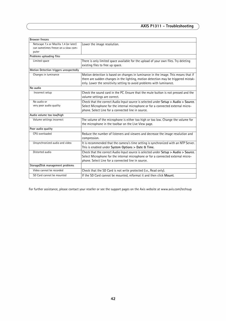
AXIS P1311 - Troubleshooting
For further assistance, please contact your reseller or see the support pages on the Axis website at www.axis.com/techsup
Browser freezesNetscape 7.x or Mozilla 1.4 (or later) can sometimes freeze on a slow com-puter
Lower the image resolution.
Problems uploading filesLimited space There is only limited space available for the upload of your own files. Try deleting
existing files to free up space.Motion Detection triggers unexpectedly
Changes in luminance Motion detection is based on changes in luminance in the image. This means that if there are sudden changes in the lighting, motion detection may be triggered mistak-enly. Lower the sensitivity setting to avoid problems with luminance.
No audio Incorrect setup Check the sound card in the PC. Ensure that the mute button is not pressed and the
volume settings are correct.No audio or very poor audio quality
Check that the correct Audio Input source is selected under Setup > Audio > Source. Select Microphone for the internal microphone or for a connected external micro-phone. Select Line for a connected line in source.
Audio volume too low/highVolume settings incorrect The volume of the microphone is either too high or too low. Change the volume for
the microphone in the toolbar on the Live View page. Poor audio quality
CPU overloaded Reduce the number of listeners and viewers and decrease the image resolution and compression.
Unsynchronized audio and video It is recommended that the camera's time setting is synchronized with an NTP Server. This is enabled under System Options > Date & Time.
Distorted audio Check that the correct Audio Input source is selected under Setup > Audio > Source. Select Microphone for the internal microphone or for a connected external micro-phone. Select Line for a connected line in source.
Storage/Disk management problems
Video cannot be recorded Check that the SD Card is not write protected (i.e., Read only).SD Card cannot be mounted If the SD Card cannot be mounted, reformat it and then click Mount.
42
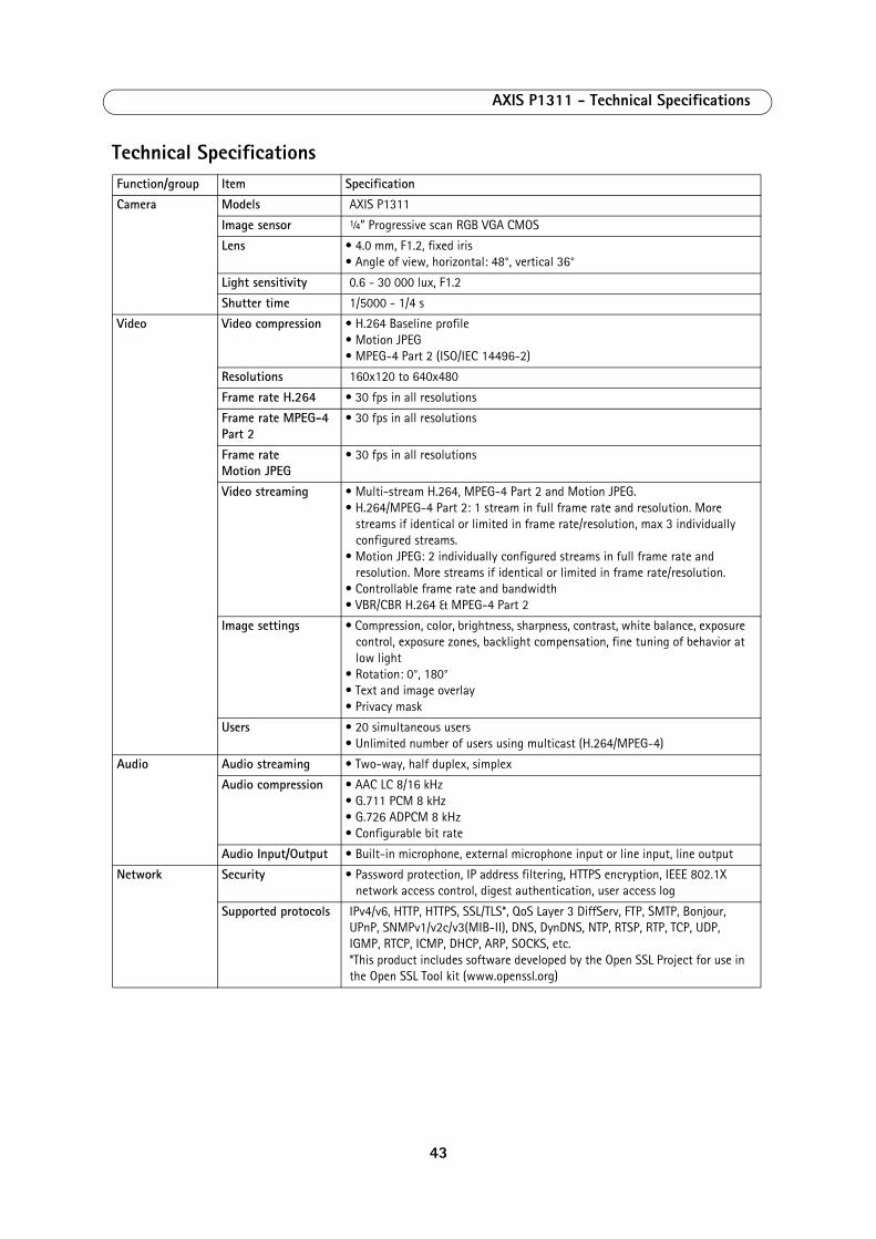
AXIS P1311 - Technical Specifications
Technical SpecificationsFunction/group Item Specification
Camera Models AXIS P1311
Image sensor ¼” Progressive scan RGB VGA CMOS
Lens • 4.0 mm, F1.2, fixed iris• Angle of view, horizontal: 48°, vertical 36°
Light sensitivity 0.6 - 30 000 lux, F1.2
Shutter time 1/5000 - 1/4 s
Video Video compression • H.264 Baseline profile• Motion JPEG• MPEG-4 Part 2 (ISO/IEC 14496-2)
Resolutions 160x120 to 640x480
Frame rate H.264 • 30 fps in all resolutions
Frame rate MPEG-4 Part 2
• 30 fps in all resolutions
Frame rate Motion JPEG
• 30 fps in all resolutions
Video streaming • Multi-stream H.264, MPEG-4 Part 2 and Motion JPEG. • H.264/MPEG-4 Part 2: 1 stream in full frame rate and resolution. More
streams if identical or limited in frame rate/resolution, max 3 individually configured streams.
• Motion JPEG: 2 individually configured streams in full frame rate and resolution. More streams if identical or limited in frame rate/resolution.
• Controllable frame rate and bandwidth• VBR/CBR H.264 & MPEG-4 Part 2
Image settings • Compression, color, brightness, sharpness, contrast, white balance, exposure control, exposure zones, backlight compensation, fine tuning of behavior at low light
• Rotation: 0°, 180°• Text and image overlay• Privacy mask
Users • 20 simultaneous users• Unlimited number of users using multicast (H.264/MPEG-4)
Audio Audio streaming • Two-way, half duplex, simplex
Audio compression • AAC LC 8/16 kHz• G.711 PCM 8 kHz• G.726 ADPCM 8 kHz• Configurable bit rate
Audio Input/Output • Built-in microphone, external microphone input or line input, line output
Network Security • Password protection, IP address filtering, HTTPS encryption, IEEE 802.1X network access control, digest authentication, user access log
Supported protocols IPv4/v6, HTTP, HTTPS, SSL/TLS*, QoS Layer 3 DiffServ, FTP, SMTP, Bonjour, UPnP, SNMPv1/v2c/v3(MIB-II), DNS, DynDNS, NTP, RTSP, RTP, TCP, UDP, IGMP, RTCP, ICMP, DHCP, ARP, SOCKS, etc.*This product includes software developed by the Open SSL Project for use in the Open SSL Tool kit (www.openssl.org)
43
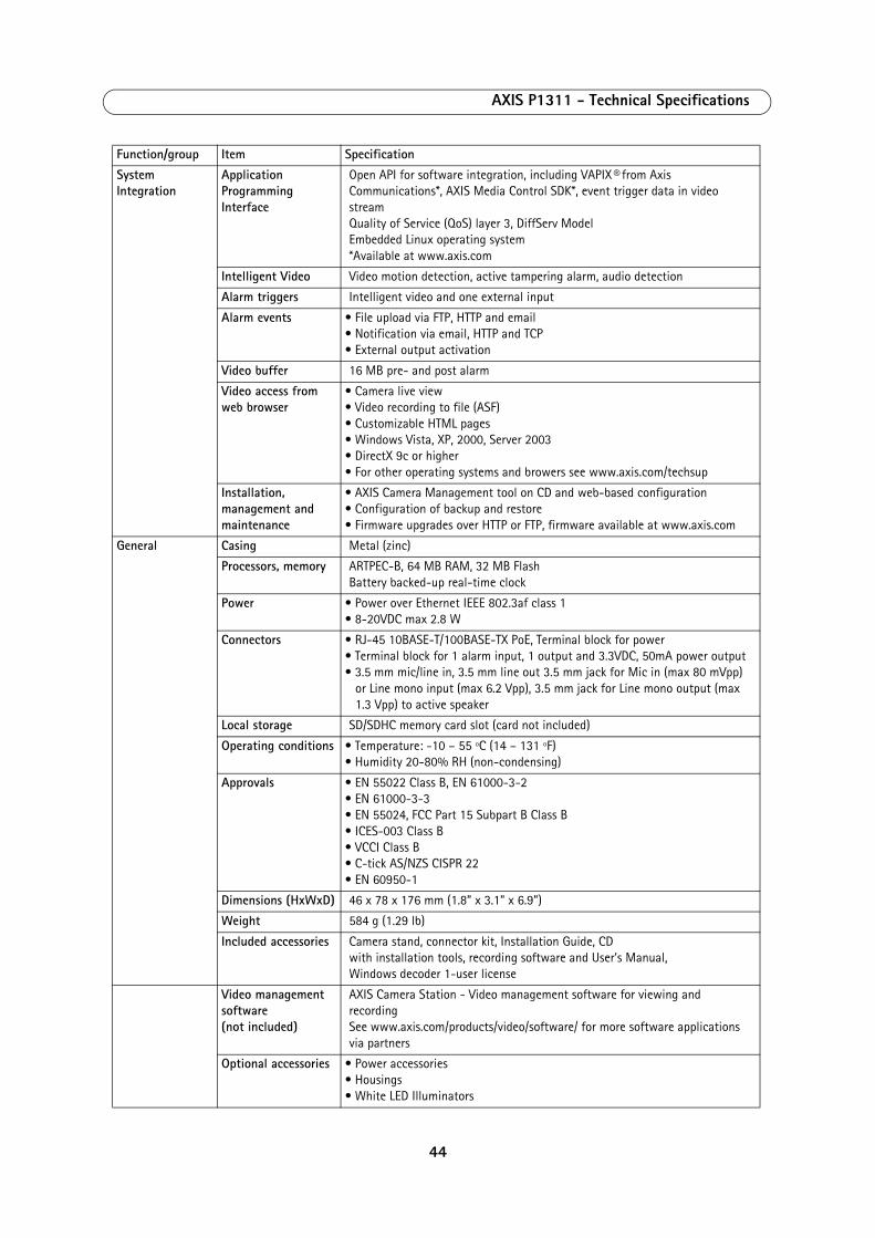
AXIS P1311 - Technical Specifications
System Integration
Application Programming Interface
Open API for software integration, including VAPIX® from Axis Communications*, AXIS Media Control SDK*, event trigger data in video streamQuality of Service (QoS) layer 3, DiffServ ModelEmbedded Linux operating system*Available at www.axis.com
Intelligent Video Video motion detection, active tampering alarm, audio detection
Alarm triggers Intelligent video and one external input
Alarm events • File upload via FTP, HTTP and email• Notification via email, HTTP and TCP• External output activation
Video buffer 16 MB pre- and post alarm
Video access from web browser
• Camera live view• Video recording to file (ASF)• Customizable HTML pages• Windows Vista, XP, 2000, Server 2003• DirectX 9c or higher• For other operating systems and browers see www.axis.com/techsup
Installation, management and maintenance
• AXIS Camera Management tool on CD and web-based configuration• Configuration of backup and restore• Firmware upgrades over HTTP or FTP, firmware available at www.axis.com
General Casing Metal (zinc)
Processors, memory ARTPEC-B, 64 MB RAM, 32 MB FlashBattery backed-up real-time clock
Power • Power over Ethernet IEEE 802.3af class 1• 8-20VDC max 2.8 W
Connectors • RJ-45 10BASE-T/100BASE-TX PoE, Terminal block for power• Terminal block for 1 alarm input, 1 output and 3.3VDC, 50mA power output• 3.5 mm mic/line in, 3.5 mm line out 3.5 mm jack for Mic in (max 80 mVpp)
or Line mono input (max 6.2 Vpp), 3.5 mm jack for Line mono output (max 1.3 Vpp) to active speaker
Local storage SD/SDHC memory card slot (card not included)
Operating conditions • Temperature: -10 – 55 ºC (14 – 131 ºF)• Humidity 20-80% RH (non-condensing)
Approvals • EN 55022 Class B, EN 61000-3-2• EN 61000-3-3• EN 55024, FCC Part 15 Subpart B Class B• ICES-003 Class B• VCCI Class B• C-tick AS/NZS CISPR 22• EN 60950-1
Dimensions (HxWxD) 46 x 78 x 176 mm (1.8” x 3.1” x 6.9”)
Weight 584 g (1.29 lb)
Included accessories Camera stand, connector kit, Installation Guide, CDwith installation tools, recording software and User’s Manual,Windows decoder 1-user license
Video management software (not included)
AXIS Camera Station - Video management software for viewing and recordingSee www.axis.com/products/video/software/ for more software applications via partners
Optional accessories • Power accessories• Housings• White LED Illuminators
Function/group Item Specification
44
AXIS P1311 - Technical Specifications
General performance considerationsWhen setting up your system, it is important to consider how various settings and situations will affect performance. Some factors affect the amount of bandwidth (the bit rate) required, others can affect the frame rate, and some affect both. If the load on the CPU reaches its maximum, this will also affect the frame rate.
The following factors are among the most important to consider:
• High image resolutions and/or lower compression levels result in larger images. Bandwidth affected. • Access by large numbers of Motion JPEG and/or unicast H.264 clients. Bandwidth affected.• Simultaneous viewing of different streams (resolution, compression) by different clients. Effect on frame rate and
bandwidth.• Accessing both Motion JPEG and H.264 video streams simultaneously. Frame rate and bandwidth affected.• Heavy usage of event settings affects the camera’s CPU load. Frame rate affected.• Enabled motion detection. Frame rate and bandwidth affected.• Heavy network utilization due to poor infrastructure. Bandwidth affected.
Viewing on poorly performing client PCs lowers perceived performance. Frame rate affected.
45
AXIS P1311 - Glossary of Terms
Glossary of Terms
ActiveX - A standard that enables software components to interact with one another in a networked environment, regardless of the language(s) used to create them. web browsers may come into contact with ActiveX controls, ActiveX documents, and ActiveX scripts. ActiveX controls are often downloaded and installed automatically as required.
Angle - The field of view, relative to a standard lens in a 35mm still camera, expressed in degrees, e.g. 30°. For practical purposes, this is the area that a lens can cover, where the angle of view is determined by the focal length of the lens. A wide-angle lens has a short focal length and covers a wider angle of view than standard or telephoto lenses, which have longer focal lengths.
ARP (Address Resolution Protocol) - This protocol is used to associate an IP address to a hardware MAC address. A request is broadcast on the local network to discover the MAC address for an IP address.
ARTPEC (Axis Real Time Picture Encoder) - This chip is used for image compression, and image processing such as conversion of raw image sensor data, color correction, sharpening, noise filtering etc.
ASIC (Application Specific Integrated Circuit) - A circuit designed for a specific application, as opposed to a general purpose circuit, such as a microprocessor.
Aspect ratio - A ratio of width to height in images. A common aspect ratio used for television screens and computer monitors is 4:3. High-definition television (HDTV) uses an aspect ratio of 16:9.
Autoiris (DC-Iris) - This special type of iris is electrically controlled by the camera, to automatically regulate the amount of light allowed to enter.
Bitmap - A bitmap is a data file representing a rectangular grid of pixels. It defines a display space and color for each pixel (or ‘bit’) in the display space. This type of image is known as a ‘raster graphic.’ GIFs and JPEGs are examples of image file types that contain bitmaps.
Because a bitmap uses this fixed raster method, it cannot easily be rescaled without losing definition. Conversely, a vector graphic image uses geometrical shapes to represent the image, and can thus be quickly rescaled.
Bit rate - The bit rate (in kbit/s or Mbit/s) is often referred to as speed, but actually defines the number of bits/time unit and not distance/time unit.
Bonjour - Also known as zero-configuration networking, Bonjour enables devices to automatically discover each other on a network, without having to enter IP addresses or configure DNS servers. Bonjour is a trademark of Apple Computer, Inc.
Broadband - In network engineering terms, this describes transmission methods where two or more signals share the same carrier. In more popular terminology, broadband is taken to mean high-speed data transmission.
CCD (Charged Coupled Device) - This light-sensitive image device used in many digital cameras is a large integrated circuit that contains hundreds of thousands of photo-sites (pixels) that convert light energy into electronic signals. Its size is measured diagonally and can be 1/4", 1/3", 1/2" or 2/3".
CGI (Common Gateway Interface) - A specification for communication between a web server and other (CGI) programs. For example, a HTML page that contains a form might use a CGI program to process the form data once it is submitted.
CIF (Common Intermediate Format) - CIF refers to the analog video resolutions 352x288 pixels (PAL) and 352x240 pixels (NTSC). See also Resolution.
Client/Server - Client/server describes the relationship between two computer programs in which one program, the client, makes a service request from another program, the server, which fulfils the request. Typically, multiple client programs share the services of a common server program. A web browser is a client program that requests services (the sending of web pages or files) from a web server.
CMOS (Complementary Metal Oxide Semiconductor) - A CMOS is a widely used type of semiconductor that uses both negative and positive circuits. Since only one of the circuit types is on at any given time, CMOS chips require less power than chips using just one type of transistor. CMOS image sensors also allow processing circuits to be included on the same chip, an advantage not possible with CCD sensors, which are also much more expensive to produce.
Codec - In communications engineering, a codec is usually a coder/decoder. Codecs are used in integrated circuits or chips that convert e.g. analog video and audio signals into a digital format for transmission. The codec also converts received digital signals back into analog format. A codec uses analog-to-digital conversion and digital-to-analog conversion in the same chip.
Codec can also mean compression/decompression, in which case it is generally taken to mean an algorithm or computer program for reducing the size of large files and programs.
Compression - See Image compression.
DC-Iris (Autoiris) - This special type of iris is electrically controlled by the camera, to automatically regulate the amount of light allowed to enter.
DHCP (Dynamic Host Configuration Protocol) - DHCP is a protocol that lets network administrators automate and centrally manage the assignment of Internet Protocol (IP) addresses to network devices in a network.
DHCP uses the concept of a ‘lease’ or amount of time that a given IP address will be valid for a computer. The lease time can vary, depending on how long a user is likely to require the network connection at a particular location.
DHCP also supports static addresses for e.g. computers running web servers, which need a permanent IP address.
46
AXIS P1311 - Glossary of Terms
DNS (Domain Name System) - DNS is used to locate and translate Internet domain names into IP (Internet Protocol) addresses. A domain name is a meaningful and easy-to-remember name for an Internet address. For example the domain name www.example.com is much easier to remember than 192.0.34.166. The translation tables for domain names are contained in Domain name servers.
Domain Server - Domains can also be used by organizations who wish to centralize the management of their (Windows) computers. Each user within a domain has an account that usually allows them to log in to and use any computer in the domain, although restrictions may also apply. The domain server is the server that authenticates the users on the network.
Duplex - See Full-duplex.
Ethernet - Ethernet is the most widely installed local area network technology. An Ethernet LAN typically uses special grades of twisted pair wires. The most commonly installed Ethernet systems are 10BASE-T and 100BASE-T10, which provide transmission speeds up to 10 Mbps and 100 Mbps respectively.
ETRAX (Ethernet Token Ring AXIS) - Axis' own microprocessor.
Factory default settings - These are the settings that originally applied for a device when it was first delivered from the factory. If it should become necessary to reset a device to its factory default settings, this will, for many devices, completely reset any settings that were changed by the user.
Firewall - A firewall works as a barrier between networks, e.g. between a Local Area Network and the Internet. The firewall ensures that only authorized users are allowed to access the one network from the other. A firewall can be software running on a computer, or it can be a standalone hardware device.
Focal length - Measured in millimeters, the focal length of a camera lens determines the width of the horizontal field of view, which in turn is measured in degrees.
FTP (File Transfer Protocol) - An application protocol that uses the TCP/IP protocols. It is used to exchange files between computers/devices on networks.
Frame - A frame is a complete video image. In the 2:1 interlaced scanning format of the RS-170 and CCIR formats, a frame is made up of two separate fields of 262.5 or 312.5 lines interlaced at 60 or 50 Hz to form a complete frame, which appears at 30 or 25 Hz. In video cameras with a progressive scan, each frame is scanned line-by-line and not interlaced; most are also displayed at 30 and 25 Hz.
Frame rate - The frame rate used to describe the frequency at which a video stream is updated is measured in frames per second (fps). A higher frame rate is advantageous when there is movement in the video stream, as it maintains image quality throughout.
Full-duplex - Transmission of data in two directions
simultaneously. In an audio system this would describe e.g. a telephone systems. Half-duplex also provides bi-directional communication, but only in one direction at a time, as in a walkie-talkie system. See also Simplex.
Gain - Gain is the amplification factor and the extent to which an analog amplifier boosts the strength of a signal. Amplification factors are usually expressed in terms of power. The decibel (dB) is the most common way of quantifying the gain of an amplifier.
Gateway - A gateway is a point in a network that acts as an entry point to another network. In a corporate network for example, a computer server acting as a gateway often also acts as a proxy server and a firewall server. A gateway is often associated with both a router, which knows where to direct a given packet of data that arrives at the gateway, and a switch, which furnishes the actual path in and out of the gateway for a given packet.
GIF (Graphics Interchange Format) - GIF is one of the most common file formats used for images in web pages. There are two versions of the format, 87a and 89a. Version 89a supports animations, i.e. a short sequence of images within a single GIF file. A GIF89a can also be specified for interlaced presentation.
GOV (Group Of VOPs) - A group of VOPs is the basic unit of an H.264 video stream. The GOV contains different types and numbers of VOPs (I-VOPs, P-VOPs) as determined by the GOV length and GOV structure. See also VOP.
GOV length - The GOV length determines the number of images (VOPs) in the GOV structure. See also GOV and VOP.
GOV structure - The GOV structure describes the composition of an H.264 video stream, as regards the type of images (I-VOPs or P-VOPs) included in the stream, and their internal order. See also GOV and VOP.
H.264 - Also known as MPEG-4 Part 10. This is the new generation compression standard for digital video. H.264 offers higher video resolution than Motion JPEG or MPEG-4 at the same bit rate and bandwidth, or the same quality video at a lower bit rate.
Half-duplex - See Full-duplex.
HTML (Hypertext Markup Language) - HTML is the set of "markup" symbols or codes inserted in a file intended for display in web browser. The markup tells the browser how to display the page's words and images for the user.
HTTP (Hypertext Transfer Protocol) - HTTP is the set of rules for exchanging files (text, graphic images, sound, video, and other multimedia files) on the web. The HTTP protocol runs on top of the TCP/IP suite of protocols.
Hub - A (network) hub is used to connect multiple devices to the network. The hub transmits all data to all devices connected to it, whereas a switch will only transmit the data to the device it is specifically intended for.
IEEE 802.11 - A family of standards for wireless LANs. The
47
AXIS P1311 - Glossary of Terms
802.11 standard supports 1 or 2 Mbit/s transmission on the 2.4 GHz band. IEEE 802.11b specifies an 11 Mbit/s data rate on the 2.4 GHz band, while 802.11a allows up to 54 Mbit/s on the 5 GHz band.
Image compression - Image compression minimizes the file size (in bytes) of an image. Two of the most common compressed image formats are JPEG and GIF.
Interlacing - Interlaced video is video captured at 50 pictures (known as fields) per second, of which every 2 consecutive fields (at half height) are then combined into 1 frame. Interlacing was developed many years ago for the analog TV world and is still used widely today. It provides good results when viewing motion in standard TV pictures, although there is always some degree of distortion in the image.
To view interlaced video on e.g. a computer monitor, the video must first be de-interlaced, to produce progressive video, which consists of complete images, one after the other, at 25 frames per second. See also Progressive scan.
IP (Internet Protocol) - The Internet Protocol is a method transmitting data over a network. Data to be sent is divided into individual and completely independent "packets." Each computer (or host) on the Internet has at least one address that uniquely identifies it from all others, and each data packet contains both the sender's address and the receiver's address.
The Internet Protocol ensures that the data packets all arrive at the intended address. As IP is a connectionless protocol, which means that there is no established connection between the communication end-points, packets can be sent via different routes and do not need to arrive at the destination in the correct order.
Once the data packets have arrived at the correct destination, another protocol - Transmission Control Protocol (TCP) - puts them in the right order. See also TCP.
IP Address - An IP address is simply an address on an IP network used by a computer/device connected to that network. IP addresses allow all the connected computers/devices to find each other and to pass data back and forth.
To avoid conflicts, each IP address on any given network must be unique. An IP address can be assigned as fixed, so that it does not change, or it can be assigned dynamically (and automatically) by DHCP.
An IP address consists of four groups (or quads) of decimal digits separated by periods, e.g. 130.5.5.25. Different parts of the address represent different things. Some part will represent the network number or address, and some other part will represent the local machine address.
See also IP (Internet Protocol).
I-VOP - See VOP.
JPEG (Joint Photographic Experts Group) - Together with the GIF file format, JPEG is an image file type commonly used on the web. A JPEG image is a bitmap, and usually has the file suffix '.jpg' or ‘.jpeg.’ When creating a JPEG image, it is possible to configure the level of compression to use. As the lowest compression (i.e. the highest quality) results in the largest file, there is a trade-off between
image quality and file size.
kbit/s (kilobits per second) - A measure of the bit rate, i.e. the rate at which bits are passing a given point. See also Bit rate.
LAN (Local Area Network) - A LAN is a group of computers and associated devices that typically share common resources within a limited geographical area.
Linux - Linux is an open source operating system within the UNIX family. Because of its robustness and availability, Linux has won popularity in the open source community and among commercial application developers.
Local storage - If a camera or video encoder supports local storage, an SD card can be inserted into the SD card slot to locally record and store a video stream.
MAC address (Media Access Control address) - A MAC address is a unique identifier associated with a piece of networking equipment, or more specifically, its interface with the network. For example, the network card in a computer has its own MAC address.
Manual iris - This is the opposite to an autoiris, i.e. the camera iris must be adjusted manually to regulate the amount of light allowed to reach the image sensor.
Mbit/s (Megabits per second) - A measure of the bit rate, i.e. the rate at which bits are passing a given point. Commonly used to give the ‘speed’ of a network. A LAN might run at 10 or 100 Mbit/s. See also Bit rate.
Monitor - A monitor is very similar to a standard television set, but lacks the electronics to pick up regular television signals.
Motion JPEG - Motion JPEG is a simple compression/decompression technique for networked video. Latency is low and image quality is guaranteed, regardless of movement or complexity of the image. Image quality is controlled by adjusting the compression level, which in turn provides control over the file size, and thereby the bit rate.
High-quality individual images from the Motion JPEG stream are easily extracted. See also JPEG.
Megapixel - See Pixel.
MPEG (Moving Picture Experts Group) - The Moving Picture Experts Group develops standards for digital video and audio compression. It operates under the auspices of the International Organization for Standardization (ISO). The MPEG standards are an evolving series, each designed for a different purpose.
MPEG-2 - MPEG-2 is the designation for a group of audio and video coding standards, and is typically used to encode audio and video for broadcast signals, including digital satellite and Cable TV. MPEG-2, with some modifications, is also the coding format used by standard commercial DVD movies.
MPEG-4 - A video compression standard that makes good use of bandwidth, and which can provide DVD-quality
48
AXIS P1311 - Glossary of Terms
video streams at less than 1 Mbit/s.
Multicast - Bandwidth-conserving technology that reduces bandwidth usage by simultaneously delivering a single stream of information to multiple network recipients.
Network connectivity - The physical (wired or wireless) and logical (protocol) connection of a computer network or an individual device to a network, such as the Internet or a LAN.
NTSC (National Television System Committee) - NTSC is the television and video standard in the United States. NTSC delivers 525 lines at 60 half-frames/second.
NWay - A network protocol that automatically negotiates the highest possible common transmission speed between two devices.
PAL (Phase Alternating Line) - PAL is the dominant television standard in Europe. PAL delivers 625 lines at 50 half-frames/second.
Ping - Ping is a basic network program used diagnostically to check the status of a network host or device. Ping can be used to see if a particular network address (IP address or host name) is occupied or not, or if the host at that address is responding normally. Ping can be run from e.g. the Windows Command prompt or the command line in UNIX.
Pixel - A pixel is one of the many tiny dots that make up a digital image. The color and intensity of each pixel represents a tiny area of the complete image.
PoE (Power over Ethernet) - Power over Ethernet provides power to a network device via the same cable as used for the network connection. This is very useful for IP-Surveillance and remote monitoring applications in places where it may be too impractical or expensive to power the device from a power outlet.
PPP (Point-to-Point Protocol) - A protocol that uses a serial interface for communication between two network devices. For example, a PC connected by a phone line to a server.
PPTP (Point-to-Point Tunneling Protocol) - A protocol (set of communication rules) that allows corporations to extend their own corporate network through private "tunnels" over the public Internet. In this way a corporation can effectively use a WAN (Wide Area Network) as a large single LAN (Local Area Network). This kind of interconnection is known as a virtual private network (VPN).
Pre/post alarm images - The images from immediately before and after an alarm. These images are stored in a buffer for later retrieval.
Progressive scan - Progressive scan, as opposed to interlaced video, scans the entire picture, line by line every sixteenth of a second. In other words, captured images are not split into separate fields as in interlaced scanning.
Computer monitors do not need interlace to show the picture on the screen, but instead show them progressively,
on one line at a time in perfect order, i.e. 1, 2, 3, 4, 5, 6, 7 etc., so there is virtually no ‘flickering’ effect. In a surveillance application, this can be critical when viewing detail within a moving image, such as a person running. A high-quality monitor is required to get the best from progressive scan. See also Interlacing.
Protocol - A special set of rules governing how two entities will communicate. Protocols are found at many levels of communication, and there are hardware protocols and software protocols.
Proxy server - In an organization that uses the Internet, a proxy server acts as an intermediary between a workstation user and the Internet. This provides security, administrative control, and a caching service. Any proxy server associated with a gateway server, or part of a gateway server, effectively separates the organization’s network from the outside network and the local firewall. It is the firewall server that protects the network against outside intrusion.
A proxy server receives requests for Internet services (such as web page requests) from many users. If the proxy server is also a cache server, it looks in its local cache of previously downloaded web pages. If it finds the page, it is returned to the user without forwarding the request to the Internet. If the page is not in the cache, the proxy server, acting as a client on behalf of the user, uses one of its own IP addresses to request the page from another server over the Internet. When the requested page is returned, the proxy server forwards it to the user that originally requested it.
P-VOP - See VOP.
Resolution - Image resolution is a measure of how much detail a digital image can hold: the greater the resolution, the greater the level of detail. Resolution can be specified as the number of pixel-columns (width) by the number of pixel-rows (height), e.g. 320x240.
Alternatively, the total number of pixels (usually in megapixels) in the image can be used. In analog systems it is also common to use other format designations, such as CIF, QCIF, 4CIF, etc.
RTCP (Real-Time Control Protocol) - RTCP provides support for real-time conferencing of groups of any size within an intranet. This support includes source identification and support for gateways like audio and video bridges as well as multicast-to-unicast translators.
RTCP offers quality-of-service feedback from receivers to the multicast group as well as support for the synchronization of different media streams.
RTP (Real-Time Transport Protocol) - RTP is an Internet protocol for the transport of real-time data, e.g. audio and video. It can be used for media-on-demand as well as interactive services such as Internet telephony.
RTSP (Real Time Streaming Protocol) - RTSP is a control protocol, and a starting point for negotiating transports such as RTP, multicast and Unicast, and for negotiating codecs.
RTSP can be considered a ‘remote control’ for controlling
49
AXIS P1311 - Glossary of Terms
the media stream delivered by a media server. RTSP servers typically use RTP as the protocol for the actual transport of audio/video data.
Router - A device that determines the next network point to which a packet should be forwarded on its way to its final destination. A router creates and/or maintains a special routing table that stores information on how best to reach certain destinations. A router is sometimes included as part of a network switch. See also switch.
Server - In general, a server is a computer program that provides services to other computer programs in the same or other computers. A computer running a server program is also frequently referred to as a server. In practice, the server may contain any number of server and client programs. A web server is the computer program that supplies the requested HTML pages or files to the client (browser).
Sharpness - This is the control of fine detail within a picture. This feature was originally introduced into color TV sets that used notch filter decoders. This filter took away all high frequency detail in the black and white region of the picture. The sharpness control attempted to put some of that detail back in the picture. Sharpness controls are mostly superfluous in today's high-end TVs. The only logical requirement for it nowadays is on a VHS machine.
Simplex - In Simplex operation, a network cable or communications channel can only send information in one direction.
SMTP (Simple Mail Transfer Protocol) - SMTP is used for sending and receiving e-mail. However, as it is ‘simple,’ it is limited in its ability to queue messages at the receiving end, and is usually used with one of two other protocols, POP3 or IMAP. These other protocols allow the user to save messages in a server mailbox and download them periodically from the server.
SMTP authentication is an extension of SMTP, whereby the client is required to log into the mail server before or during the sending of email. It can be used to allow legitimate users to send email while denying the service to unauthorized users, such as spammers.
SNMP (Simple Network Management Protocol) - SNMP forms part of the Internet Protocol suite, as defined by the Internet Engineering Task Force. The protocol can support monitoring of network-attached devices for any conditions that warrant administrative attention.
Sockets - Sockets are a method for communication between a client program and a server program over a network. A socket is defined as ‘the endpoint in a connection.’ Sockets are created and used with a set of programming requests or ‘function calls’ sometimes called the sockets application programming interface (API).
SSL/TSL (Secure Socket Layer/Transport Layer Security)These two protocols (SSL is succeeded by TSL) are cryptographic protocols that provide secure communication on a network. SSL is commonly used over HTTP to form HTTPS, as used e.g. on the Internet for electronic financial transactions. SSL uses public key
certificates to verify the identity of the server.
Subnet/subnet mask - A subnet is an identifiably separate part of an organization's network. Typically, a subnet may represent all the machines at one geographic location, in one building, or on the same local area network (LAN). Having an organization's network divided into subnets allows it to be connected to the Internet with a single shared network address.
The subnet mask is the part of the IP address that tells a network router how to find the subnet that the data packet should be delivered to. Using a subnet mask saves the router having to handle the entire 32-bit IP address; it simply looks at the bits selected by the mask.
Switch - A switch is a network device that connects network segments together, and which selects a path for sending a unit of data to its next destination. In general, a switch is a simpler and faster mechanism than a router, which requires knowledge about the network and how to determine the route. Some switches include the router function. See also Router.
TCP (Transmission Control Protocol) - TCP is used along with the Internet Protocol (IP) to transmit data as packets between computers over the network. While IP takes care of the actual packet delivery, TCP keeps track of the individual packets that the communication (e.g. requested a web page file) is divided into, and, when all packets have arrived at their destination, it reassembles them to re-form the complete file.
TCP is a connection-oriented protocol, which means that a connection is established between the two end-points and is maintained until the data has been successfully exchanged between the communicating applications.
Telnet - Telnet is a simple method with which to access another network device, e.g. a computer. The HTTP protocol and the FTP protocols allow you to request specific files from remote computers, but do not allow you logon as a user of that computer. With Telnet, you log on as a regular user with whatever privileges you may have been granted for specific applications and data residing on that computer.
UDP (User Datagram Protocol) - UDP is a communications protocol that offers limited service for exchanging data in a network that uses the Internet Protocol (IP). UDP is an alternative to the Transmission Control Protocol (TCP). The advantage of UDP is that it is not required to deliver all data and may drop network packets when there is e.g. network congestion. This is suitable for live video, as there is no point in re-transmitting old information that will not be displayed anyway.
Unicast - Communication between a single sender and a single receiver over a network. A new connection is established for each new user.
URL (Uniform Resource Locator) - An "address" on the network.
Varifocal lens - A varifocal lens provides a wide range of focal lengths, as opposed to a lens with a fixed focal length, which only provides one.
50
AXIS P1311 - Glossary of Terms
VPN (Virtual Private Network) - This creates a secure "tunnel" between the points within the VPN. Only devices with the correct "key" will be able to work within the VPN. The VPN network can be within a company LAN (Local Area Network), but different sites can also be connected over the Internet in a secure way. One common use for VPN is for connecting a remote computer to the corporate network, via e.g. a direct phone line or via the Internet.
VOP (Video Object Plane) - A VOP is an image frame in an H.264 video stream. There are several types of VOP:
- An I-VOP is complete image frame.
- A P-VOP codes the differences between images, as long as it is more efficient to do so. Otherwise it codes the whole image, which may also be a completely new image.
WAN (Wide-Area-Network) - Similar to a LAN, but on a larger geographical scale.
W-LAN (Wireless LAN) - A wireless LAN is a wireless local area network that uses radio waves as its carrier: where the network connections for end-users are wireless. The main network structure usually uses cables.
Web server - A web server is a program, which allows web browsers to retrieve files from computers connected to the Internet. The web server listens for requests from web browsers and upon receiving a request for a file sends it back to the browser.
The primary function of a web server is to serve pages to other remote computers; consequently, it needs to be installed on a computer that is permanently connected to the Internet. It also controls access to the server whilst monitoring and logging server access statistics.
WEP (Wireless Equivalent Privacy) - A wireless security protocol, specified in the IEEE 802.11 standard, which is designed to provide a wireless local area network (WLAN) with a level of security and privacy comparable to that usually expected of a wired LAN. Security is at two different levels; 40-bit and 128-bit encryption. The higher the bit number, the more secure the encryption.
WPA-PSK (Wi-Fi Protected Access - Pre-Shared Key) - This wireless encryption method uses a pre-shared key (PSK) for key management. Keys can usually be entered as manual hex values, as hexadecimal characters, or as a Passphrase. WPA-PSK provides a greater degree of security than WEP.
Zoom lens - A zoom lens can be moved (zoomed) to enlarge the view of an object to show more detail.
51
AXIS P1311 - Index
Index
AAction Buttons 9, 19Active/Inactive 19Administrator 13Alarm 23, 37AMC 6ARP/Ping 28Audio 13Audio input 16Audio output 17Audio Settings 16AXIS Media Control 16
BBackup 33Bit Rate 14Bonjour 6Buffer Size 21Buffers 21
CCamera tampering 22Control Button 35
DDate & Time 27Default Viewer 18Disk Management 32DNS Configuration 29DNS Server 29Domain Name 29
EEmergency Recovery 38Enable ARP/Ping 28Event Servers 20Events 20
FFrame Rate 13FTP Server 20
GGOV Settings 14
HH.264 13, 14Half duplex 16Host Name 29HTTP Server 20HTTPS 7, 26, 29
II/O Ports 32
52
IEEE 802.1X 27Input 37IP Address Filtering 26
LLive View 9Live View Config 18Local storage 32Logs & Reports 33
MMotion Detection 23, 37MPEG-4 14
NNAT traversal 7, 29, 30Network Settings 28NTP Server 28
OOutput 37Output Buttons 19
PPinout - I/O connectors 37Port Status 24Ports & Devices 32Post-trigger Buffer 21Pre-trigger Buffer 21Pulse 19
QQoS (Quality of Service) 31QuickTime 12, 18
RRecording List 25Recovery 38Referrals 26Restore 33
SScheduled Event 22Security 26Server Report 39Server Time 27SNMP 31Storage 32Support 33System Options 26
TTCP Server 20TCP/IP Settings 28Time Mode 28Troubleshooting 38

AXIS P1311 - Index
UUpgrade Server 33UPnP 29, 32Users 26
VVideo Stream 13
WWDR 15
53