Embed Size (px)
Citation preview

AXIS P5635-E Mk II PTZ Dome Network Camera
User Manual
AXIS P5635-E Mk II PTZ Dome Network Camera
Table of Contents
Product overview . . . . . . . . . . . . . . . . . . . . . . . . . . . . . . . . . . . . . . . . . . . 3Find the device on the network . . . . . . . . . . . . . . . . . . . . . . . . . . . . . . . . 4
Access the device . . . . . . . . . . . . . . . . . . . . . . . . . . . . . . . . . . . . . . . . . . . . . . . 4About secure passwords . . . . . . . . . . . . . . . . . . . . . . . . . . . . . . . . . . . . . . . . . . 4
Setup . . . . . . . . . . . . . . . . . . . . . . . . . . . . . . . . . . . . . . . . . . . . . . . . . . . . . 5Need more help? . . . . . . . . . . . . . . . . . . . . . . . . . . . . . . . . . . . . . . . . . . . . . . . . 5Image quality . . . . . . . . . . . . . . . . . . . . . . . . . . . . . . . . . . . . . . . . . . . . . . . . . . . 5Streaming and storage . . . . . . . . . . . . . . . . . . . . . . . . . . . . . . . . . . . . . . . . . . . 7Overlays . . . . . . . . . . . . . . . . . . . . . . . . . . . . . . . . . . . . . . . . . . . . . . . . . . . . . . . 8PTZ (Pan Tilt Zoom) . . . . . . . . . . . . . . . . . . . . . . . . . . . . . . . . . . . . . . . . . . . . . . 8Events . . . . . . . . . . . . . . . . . . . . . . . . . . . . . . . . . . . . . . . . . . . . . . . . . . . . . . . . 9Applications . . . . . . . . . . . . . . . . . . . . . . . . . . . . . . . . . . . . . . . . . . . . . . . . . . . . 12
Troubleshooting . . . . . . . . . . . . . . . . . . . . . . . . . . . . . . . . . . . . . . . . . . . . 13Reset to factory default settings . . . . . . . . . . . . . . . . . . . . . . . . . . . . . . . . . . . 13Check the current firmware . . . . . . . . . . . . . . . . . . . . . . . . . . . . . . . . . . . . . . . 13Upgrade the firmware . . . . . . . . . . . . . . . . . . . . . . . . . . . . . . . . . . . . . . . . . . . . 13Technical issues, clues and solutions . . . . . . . . . . . . . . . . . . . . . . . . . . . . . . . . 14Performance considerations . . . . . . . . . . . . . . . . . . . . . . . . . . . . . . . . . . . . . . . 15
Specifications . . . . . . . . . . . . . . . . . . . . . . . . . . . . . . . . . . . . . . . . . . . . . . 17LED indicators . . . . . . . . . . . . . . . . . . . . . . . . . . . . . . . . . . . . . . . . . . . . . . . . . . 17SD card slot . . . . . . . . . . . . . . . . . . . . . . . . . . . . . . . . . . . . . . . . . . . . . . . . . . . . 17Buttons . . . . . . . . . . . . . . . . . . . . . . . . . . . . . . . . . . . . . . . . . . . . . . . . . . . . . . . 17Connectors . . . . . . . . . . . . . . . . . . . . . . . . . . . . . . . . . . . . . . . . . . . . . . . . . . . . 17AXIS Multicable C I/O Audio Power . . . . . . . . . . . . . . . . . . . . . . . . . . . . . . . . . 18Axis 10-pin push-pull system connector (sold separately) . . . . . . . . . . . . . . . 19
2
AXIS P5635-E Mk II PTZ Dome Network Camera
Product overview
Product overview
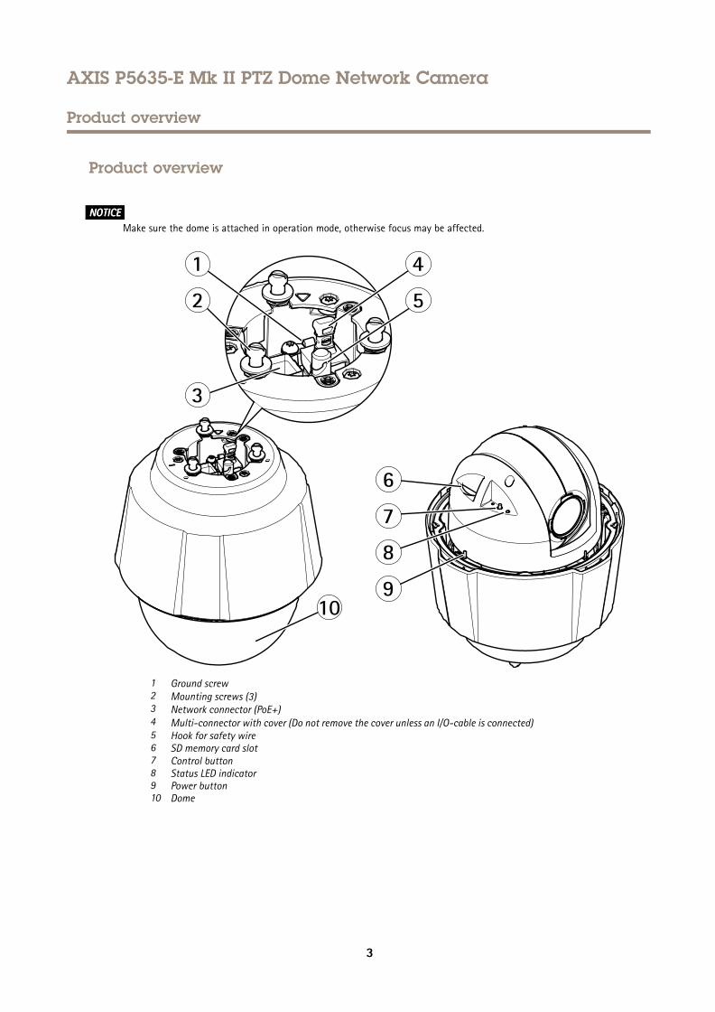
NONONOTICETICETICEMake sure the dome is attached in operation mode, otherwise focus may be affected.
1 Ground screw2 Mounting screws (3)3 Network connector (PoE+)4 Multi-connector with cover (Do not remove the cover unless an I/O-cable is connected)5 Hook for safety wire6 SD memory card slot7 Control button8 Status LED indicator9 Power button10 Dome
3
AXIS P5635-E Mk II PTZ Dome Network Camera
Find the device on the network
Find the device on the network
To find Axis devices on the network and assign them IP addresses in Windows®, use AXIS IP Utility or AXIS Device Manager. Bothapplications are free and can be downloaded from axis.com/support
For more information about how to find and assign IP addresses, see the document How to assign an IP address and access yourdevice on the device page at axis.com
Access the device1. Open a browser and enter the IP address or host name of the Axis device.
If you have a Mac computer (OS X), go to Safari, click on Bonjour and select the device from the drop-down list. To addBonjour as a browser bookmark, go to Safari > Preferences.
If you do not know the IP address, use AXIS IP Utility or AXIS Device Manager to find the device on the network.
2. Enter the username and password. If you access the device for the first time, you must set the root password. SeeSet a secure password for the root account on page 4 .
3. The live view page opens in your browser.
About secure passwordsImportant
Axis devices send the initially set password in clear text over the network. To protect your device after the first login, setup a secure and encrypted HTTPS connection and then change the password.
The device password is the primary protection for your data and services. Axis devices do not impose a password policy as theymay be used in various types of installations.
To protect your data we strongly recommend that you:
• Use a password with at least 8 characters, preferably created by a password generator.
• Don’t expose the password.
• Change the password at a recurring interval, at least once a year.
Set a secure password for the root account
ImportantThe default administrator username is root. If the password for root is lost, reset the device to factory default settings.
1. Type a password. Follow the instructions about secure passwords. See About secure passwords on page 4 .
2. Retype the password to confirm the spelling.
3. Click Create login. The password has now been configured.
4
AXIS P5635-E Mk II PTZ Dome Network Camera
Setup
Setup
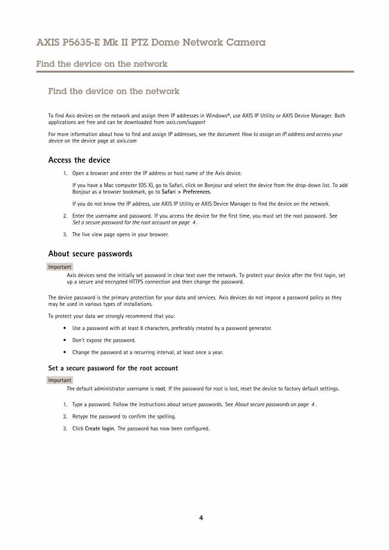
Need more help?You can access the built-in help from the device’s webpage. The help provides more detailed information on the device’s features andtheir settings.
Image quality
How to focus faster using focus recall areas
To save the focus settings at a specific pan/tilt range, add a focus recall area. Each time the camera moves into that area it recalls thepreviously saved focus. It’s enough to cover half of the focus recall area in the live view.
We recommend the focus recall feature in the following scenarios:
• When there is a lot of manual operation in live view, for example with a joystick.
• Where PTZ preset positions with manual focus are not efficient, for example movements where the focus setting changescontinuously.
• In low-light scenarios, where the autofocus is challenged by the lighting conditions.
Important• The focus recall overrides the camera’s autofocus at the specific pan/tilt range.
• A preset position overrides the focus setting saved in the focus recall area.
• The maximum amount of focus recall areas is 20.
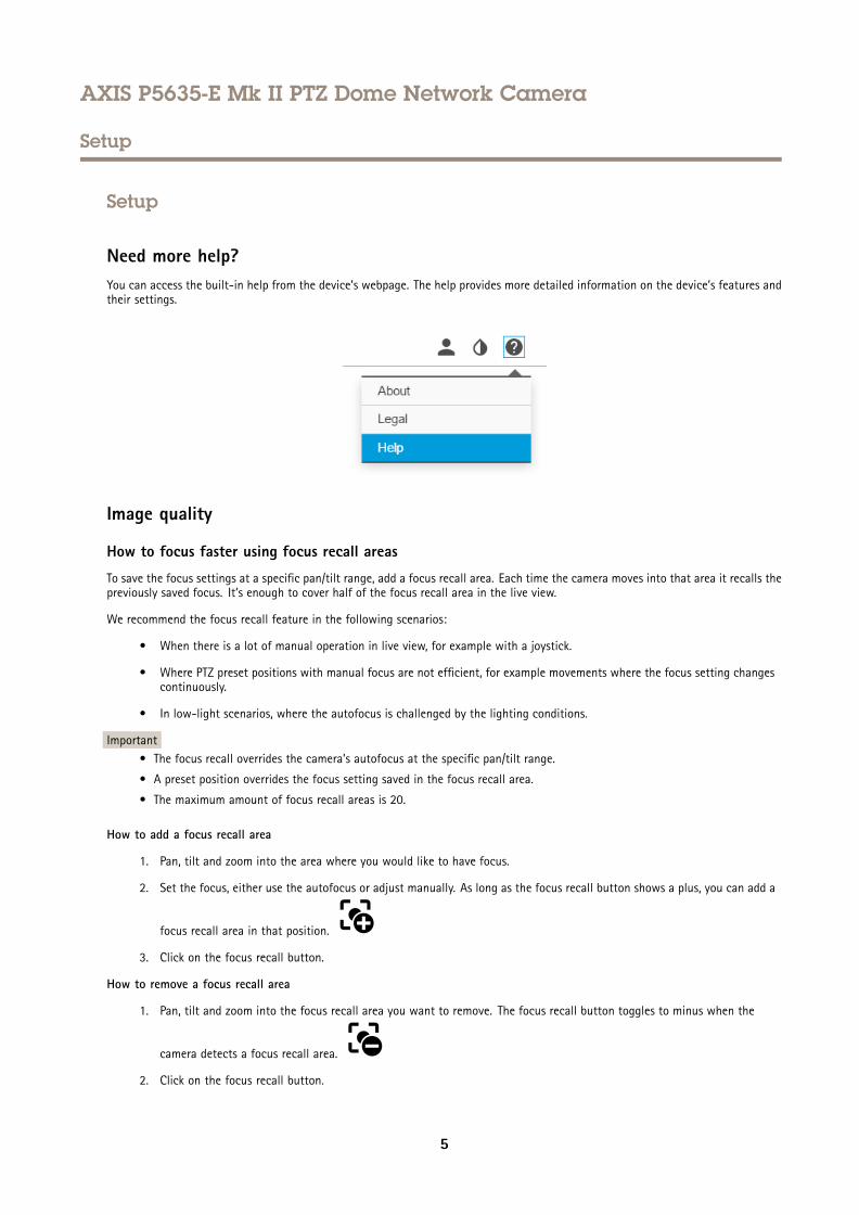
How to add a focus recall area
1. Pan, tilt and zoom into the area where you would like to have focus.
2. Set the focus, either use the autofocus or adjust manually. As long as the focus recall button shows a plus, you can add a
focus recall area in that position.
3. Click on the focus recall button.
How to remove a focus recall area
1. Pan, tilt and zoom into the focus recall area you want to remove. The focus recall button toggles to minus when the
camera detects a focus recall area.
2. Click on the focus recall button.
5
AXIS P5635-E Mk II PTZ Dome Network Camera
Setup
Handle scenes with strong backlight
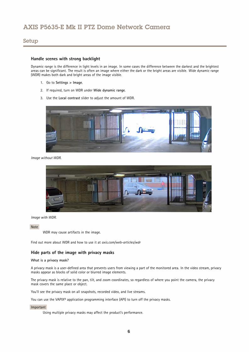
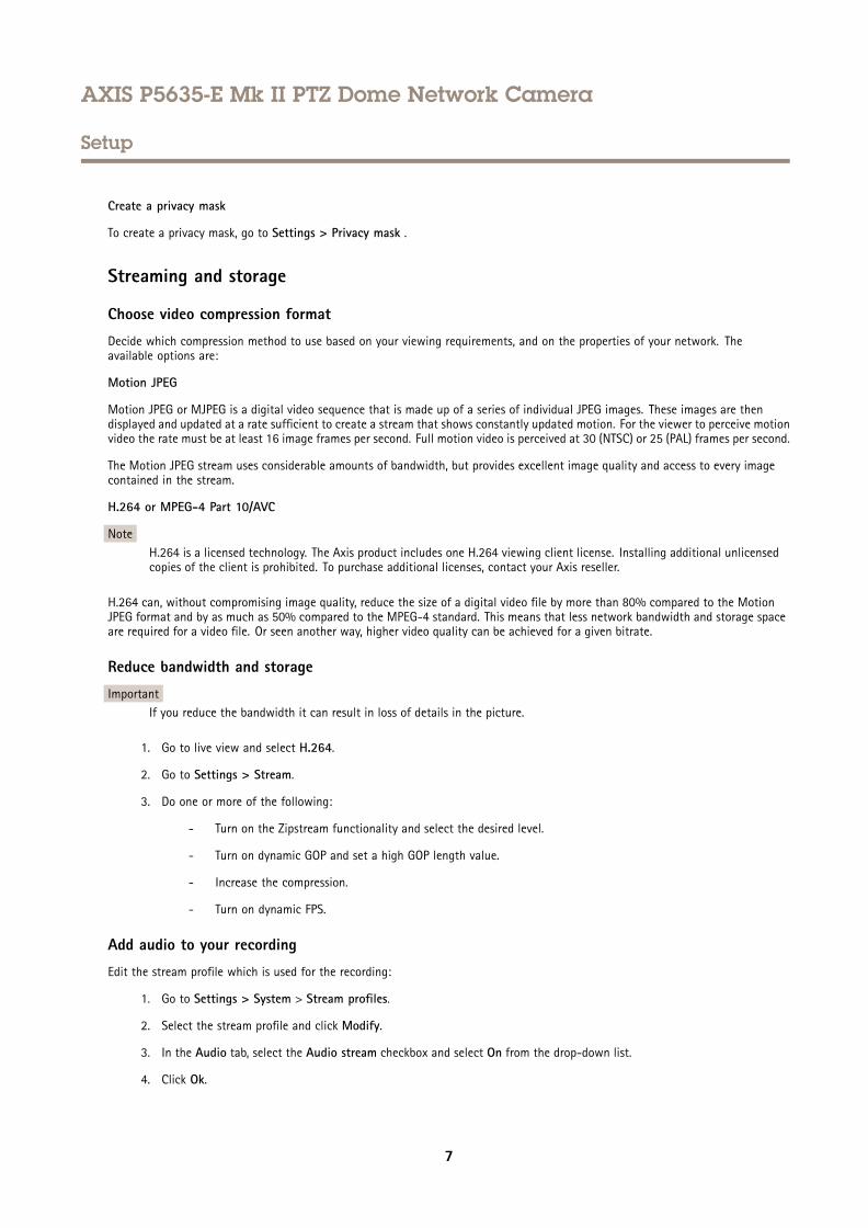
Dynamic range is the difference in light levels in an image. In some cases the difference between the darkest and the brightestareas can be significant. The result is often an image where either the dark or the bright areas are visible. Wide dynamic range(WDR) makes both dark and bright areas of the image visible.
1. Go to Settings > Image.
2. If required, turn on WDR under Wide dynamic range.
3. Use the Local contrast slider to adjust the amount of WDR.
Image without WDR.
Image with WDR.
NoteWDR may cause artifacts in the image.
Find out more about WDR and how to use it at axis.com/web-articles/wdr
Hide parts of the image with privacy masks
What is a privacy mask?
A privacy mask is a user-defined area that prevents users from viewing a part of the monitored area. In the video stream, privacymasks appear as blocks of solid color or blurred image elements.
The privacy mask is relative to the pan, tilt, and zoom coordinates, so regardless of where you point the camera, the privacymask covers the same place or object.
You’ll see the privacy mask on all snapshots, recorded video, and live streams.
You can use the VAPIX® application programming interface (API) to turn off the privacy masks.
ImportantUsing multiple privacy masks may affect the product’s performance.
6
AXIS P5635-E Mk II PTZ Dome Network Camera
Setup
Create a privacy mask
To create a privacy mask, go to Settings > Privacy mask .
Streaming and storage
Choose video compression format
Decide which compression method to use based on your viewing requirements, and on the properties of your network. Theavailable options are:
Motion JPEG
Motion JPEG or MJPEG is a digital video sequence that is made up of a series of individual JPEG images. These images are thendisplayed and updated at a rate sufficient to create a stream that shows constantly updated motion. For the viewer to perceive motionvideo the rate must be at least 16 image frames per second. Full motion video is perceived at 30 (NTSC) or 25 (PAL) frames per second.
The Motion JPEG stream uses considerable amounts of bandwidth, but provides excellent image quality and access to every imagecontained in the stream.
H.264 or MPEG-4 Part 10/AVC
NoteH.264 is a licensed technology. The Axis product includes one H.264 viewing client license. Installing additional unlicensedcopies of the client is prohibited. To purchase additional licenses, contact your Axis reseller.
H.264 can, without compromising image quality, reduce the size of a digital video file by more than 80% compared to the MotionJPEG format and by as much as 50% compared to the MPEG-4 standard. This means that less network bandwidth and storage spaceare required for a video file. Or seen another way, higher video quality can be achieved for a given bitrate.
Reduce bandwidth and storage
ImportantIf you reduce the bandwidth it can result in loss of details in the picture.
1. Go to live view and select H.264.
2. Go to Settings > Stream.
3. Do one or more of the following:
- Turn on the Zipstream functionality and select the desired level.
- Turn on dynamic GOP and set a high GOP length value.
- Increase the compression.
- Turn on dynamic FPS.
Add audio to your recording
Edit the stream profile which is used for the recording:
1. Go to Settings > System > Stream profiles.
2. Select the stream profile and click Modify.
3. In the Audio tab, select the Audio stream checkbox and select On from the drop-down list.
4. Click Ok.
7
AXIS P5635-E Mk II PTZ Dome Network Camera
Setup
Overlays
About overlays
Overlays are superimposed over the video stream. They are used to provide extra information during recordings, such as a timestamp,or during product installation and configuration.
Display the pan or tilt position as a text overlay
It may be useful to retrieve, for instance from a recorded video, the pan or tilt position in degrees in which an event has taken place.This can be obtained by including the position in the image as a text overlay, using a so-called modifier.
1. Go to Settings > Overlay.
2. In the text field, enter #x to show the pan position.
Enter #y to show the tilt position.
3. Choose alignment, text size and appearance.
4. Include the text overlay.
5. The current pan and tilt positions show up in the live view image and in the recording.
PTZ (Pan Tilt Zoom)
Limit the pan, tilt, and zoom movements
As an example, you might need to protect the privacy of residents living in apartment buildings located close to a parking lot thatyou wish to surveil. To do this, you can limit the pan, tilt, and zoom movements, so that the view does not cover the apartmentbuildings. Go to Settings > PTZ > Limits.
About guard tours
A guard tour displays the video stream from different preset positions either in a predetermined or random order, and for configurableperiods of time. Once started, a guard tour continues to run until stopped, even when there are no clients (web browsers) viewing theimages.
Create a guard tour with preset positions
1. Go to Settings > PTZ > Guard tours
2. Click +.
3. Select Preset position.
4. To edit the guard tour’s properties, click
5. Type a name for the guard tour and specify the pause length in minutes between each tour.
6. If you want the guard tour to go to the preset positions in a random order, turn on Shuffle.
7. Click Done.
8. Click Add to add the preset positions that you want in your guard tour.
9. Click Done to exit the guard tour settings.
10. To schedule the guard tour, go to System > Events.
8
AXIS P5635-E Mk II PTZ Dome Network Camera
Setup
Events
Rules and alerts
You can create rules to make your device perform an action when certain events occur. A rule consists of conditions and actions.The conditions can be used to trigger the actions. For example, the device can start a recording or send an email when it detectsmotion, or show an overlay text when it records.
Direct the camera to a preset position when the camera detects motion
This example explains how to set up the camera to go to a preset position when it detects motion in the image.
Make sure the AXIS Video Motion Detection application is running:
1. Go to Settings > Apps > AXIS Video Motion Detection.
2. Start the application if it is not already running.
3. Make sure you have set up the application according to your needs.
Add a preset position:
Go to Settings > PTZ and set where you want the camera to be directed by creating a preset position.
Create an action rule:
1. Go to Settings > System > Events > Action rules and add an action rule.
2. Type a name for the action rule.
3. From the list of triggers, select Applications and then select AXIS Video Motion Detection (VMD).
4. From the list of actions, select PTZ Control and then select Preset Position.
5. Select the preset position you want the camera to go to.
6. Click Ok.
Direct the camera and open the lock to a gate when someone is nearby
This example explains how to direct the camera and open a gate when someone wants to enter during daytime. This is done byconnecting a PIR detector to the product’s input port and a switch relay to the product’s output port via the multicable.
Required hardware
• Multicable (sold separately), see .
• Mounted PIR detector
• Switch relay connected to the gate lock, in this case the switch is normally closed (NC)
• Connecting wires
Physical connection
1. Remove the plug from the camera’s multi-connector and connect the multicable.
2. Connect the wires from the PIR detector to the input pin, see AXIS Multicable C I/O Audio Power on page 18.
3. Connect the wires from the switch to the output pin, see AXIS Multicable C I/O Audio Power on page 18.
Configure I/O ports
You need to connect the switch relay to the camera from the camera’s webpage. First, configure the I/O ports:
9
AXIS P5635-E Mk II PTZ Dome Network Camera
Setup
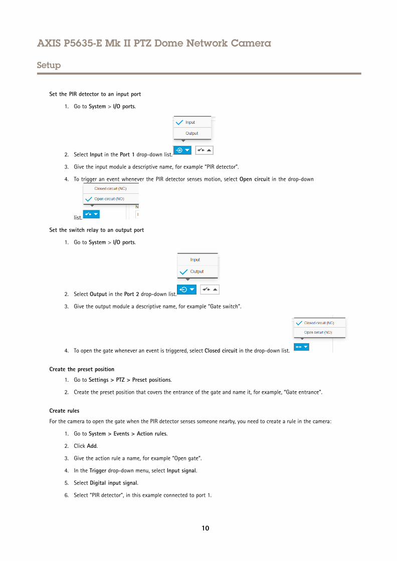
Set the PIR detector to an input port
1. Go to System > I/O ports.
2. Select Input in the Port 1 drop-down list.
3. Give the input module a descriptive name, for example “PIR detector”.
4. To trigger an event whenever the PIR detector senses motion, select Open circuit in the drop-down
list.
Set the switch relay to an output port
1. Go to System > I/O ports.
2. Select Output in the Port 2 drop-down list.
3. Give the output module a descriptive name, for example “Gate switch”.
4. To open the gate whenever an event is triggered, select Closed circuit in the drop-down list.
Create the preset position
1. Go to Settings > PTZ > Preset positions.
2. Create the preset position that covers the entrance of the gate and name it, for example, “Gate entrance”.
Create rules
For the camera to open the gate when the PIR detector senses someone nearby, you need to create a rule in the camera:
1. Go to System > Events > Action rules.
2. Click Add.
3. Give the action rule a name, for example “Open gate”.
4. In the Trigger drop-down menu, select Input signal.
5. Select Digital input signal.
6. Select ”PIR detector”, in this example connected to port 1.
10
AXIS P5635-E Mk II PTZ Dome Network Camera
Setup
7. Under Actions, select Output port from the Type drop-down menu.
8. In the Port drop-down menu, select “Gate switch”.
9. Click Ok.
10. Create another action rule with the name “Direct the camera to the gate"
11. Select the same input signal as before, but as action select the previously created “Gate entrance” preset position.
12. Click Ok.
Record video when the camera detects loud noises
This example explains how to set up the camera to start recording to the SD card five seconds before it detects loud noise and tostop one minute after.
Turn on audio:
1. Set up the stream profile to include audio, see Add audio to your recording on page 7 .
Set up audio detection:
2. Go to Settings > System > Detectors > Audio detection.
3. Adjust the alarm level according to your needs.
Create a rule:
4. Go to Settings > System > Events and add a rule.
5. Type a name for the rule.
6. In the list of triggers, select Detectors and then select Audio Detection.
7. In the list of actions, select Record video.
8. Select the stream profile where audio has been turned on or create a new one.
9. Enable and set the pre-trigger time to 5 seconds.
10. Enable While the rule is active.
11. Enable and set the post-trigger time to 60 seconds.
12. Select SD card from the list of storage options.
13. Click OK.
Zoom in on a specific area automatically with gatekeeper
This example explains how to use the gatekeeper functionality to make the camera zoom in automatically on the license plate of acar that passes through a gate. When the car has passed, the camera zooms out to the home position.
Create the preset positions:
1. Go to Settings > PTZ > Preset positions.
2. Create the home position that includes the entrance of the gate.
3. Create the zoomed-in preset position so that it covers the area in the image where you assume that the license platewill appear.
Create a motion detection profile:
11
AXIS P5635-E Mk II PTZ Dome Network Camera
Setup
4. Go to Settings > Apps and open AXIS Video Motion Detection.
5. Create a profile that covers the entrance of the gate and then save the profile.
Create a rule:
6. Go to Settings > System > Events and add a rule.
7. Name the rule “Gatekeeper”.
8. In the trigger list, select Applications and then select the previously created motion detection profile.
9. In the action list, select the previously created preset position.
10. Click OK.
Record video when the camera detects impact
Shock detection allows the camera to detect tampering caused by vibrations or shock. Vibrations due to the environment or to anobject can trigger an action depending on the shock sensitivity range, which can be set from 0 to 100. In this scenario, someone isthrowing rocks at the camera after hours and you would like to get a video clip of the event.
1. Go to Settings > System > Detectors.
2. Set shock detection to on, and set a value for the shock sensitivity.
Create an action rule:
3. Go to Settings > System > Events and add an action rule.
4. Type a name for the action rule.
5. From the list of triggers, select Detectors and then select Shock detection.
6. From the list of schedules, select After Hours.
7. From the list of actions, select Send Video Clip.
8. Select an existing stream profile or create a new one.
9. Enable and set the pre-trigger time to 5 seconds.
10. Enable While the rule is active.
11. Enable and set the post-trigger time to 60 seconds.
12. Select an existing recipient or create a new one.
13. Click OK.
Applications
Applications
AXIS Camera Application Platform (ACAP) is an open platform that enables third parties to develop analytics and other applicationsfor Axis products. To find out more about available applications, downloads, trials and licenses, go to axis.com/applications
To find the user manuals for Axis applications, go to axis.com
Note• Several applications can run at the same time but some applications might not be compatible with each other. Certaincombinations of applications might require too much processing power or memory resources when run in parallel. Verifythat the applications work together before deployment.
12
AXIS P5635-E Mk II PTZ Dome Network Camera
Troubleshooting
Troubleshooting
If you can’t find what you’re looking for here, try the troubleshooting section at axis.com/support
Reset to factory default settingsImportant
Reset to factory default should be used with caution. A reset to factory default resets all settings, including the IP address, tothe factory default values.
To reset the product to the factory default settings:
1. Press and hold the control button and the power button for 15–30 seconds until the status LED indicator flashes amber.See Product overview on page 3 .
2. Release the control button but continue to hold down the power button until the status LED indicator turns green.
3. Release the power button and assemble the product.
4. The process is now complete. The product has been reset to the factory default settings. If no DHCP server is available onthe network, the default IP address is 192.168.0.90
5. Using the installation and management software tools to assign an IP address, set the password and access the videostream.
It is also possible to reset parameters to factory default through the web interface. Go to Settings > System > Maintenance andclick Default.
Check the current firmwareFirmware is the software that determines the functionality of network devices. One of your first actions when troubleshooting aproblem should be to check the current firmware version. The latest version may contain a correction that fixes your particularproblem.
To check the current firmware:
1. Go to the product’s webpage.
2. Click on the help menu.
3. Click About.
Upgrade the firmwareImportant
Preconfigured and customized settings are saved when the firmware is upgraded (provided that the features are available inthe new firmware) although this is not guaranteed by Axis Communications AB.
ImportantMake sure the cover is attached during upgrade to avoid installation failure.
ImportantMake sure the product remains connected to the power source throughout the upgrade process.
13
AXIS P5635-E Mk II PTZ Dome Network Camera
Troubleshooting
NoteWhen you upgrade the product with the latest firmware in the active track, the product receives the latest functionalityavailable. Always read the upgrade instructions and release notes available with each new release before upgrading thefirmware. To find the latest firmware and the release notes, go to axis.com/support/firmware
1. Download the firmware file to your computer, available free of charge at axis.com/support/firmware
2. Log in to the product as an administrator.
3. Go to Settings > System > Maintenance. Follow the instructions on the page. When the upgrade has finished, theproduct restarts automatically.
AXIS Device Manager can be used for multiple upgrades. Find out more at axis.com/products/axis-device-manager
Technical issues, clues and solutionsIf you can’t find what you’re looking for here, try the troubleshooting section at axis.com/support
Problems upgrading the firmware
Firmware upgrade failure If the firmware upgrade fails, the device reloads the previous firmware. The most common reasonis that the wrong firmware file has been uploaded. Check that the name of the firmware filecorresponds to your device and try again.
Problems setting the IP address
The device is located on adifferent subnet
If the IP address intended for the device and the IP address of the computer used to access thedevice are located on different subnets, you cannot set the IP address. Contact your networkadministrator to obtain an IP address.
The IP address is being usedby another device
Disconnect the Axis device from the network. Run the ping command (in a Command/DOS window,type ping and the IP address of the device):
• If you receive: Reply from <IP address>: bytes=32; time=10...this means that the IP address may already be in use by another device on the network.Obtain a new IP address from the network administrator and reinstall the device.
• If you receive: Request timed out, this means that the IP address is availablefor use with the Axis device. Check all cabling and reinstall the device.
Possible IP address conflictwith another device on thesame subnet
The static IP address in the Axis device is used before the DHCP server sets a dynamic address.This means that if the same default static IP address is also used by another device, there maybe problems accessing the device.
The device cannot be accessed from a browser
Cannot log in When HTTPS is enabled, ensure that the correct protocol (HTTP or HTTPS) is used when attemptingto log in. You may need to manually type http or https in the browser’s address field.
If the password for the user root is lost, the device must be reset to the factory default settings.See Reset to factory default settings on page 13.
The IP address has beenchanged by DHCP
IP addresses obtained from a DHCP server are dynamic and may change. If the IP address has beenchanged, use AXIS IP Utility or AXIS Device Manager to locate the device on the network. Identifythe device using its model or serial number, or by the DNS name (if the name has been configured).
If required, a static IP address can be assigned manually. For instructions, go to axis.com/support
Certificate error when usingIEEE 802.1X
For authentication to work properly, the date and time settings in the Axis device must besynchronized with an NTP server. Go to Settings > System > Date and time
14
AXIS P5635-E Mk II PTZ Dome Network Camera
Troubleshooting
The device is accessible locally but not externally
To access the device externally, we recommend using one of the following applications for Windows®:
• AXIS Companion: free of charge, ideal for small systems with basic surveillance needs.• AXIS Camera Station: 30-day trial version free of charge, ideal for small to mid-size systems.
For instructions and download, go to axis.com/products/axis-companion
Problems with streaming
Multicast H.264 onlyaccessible by local clients
Check if your router supports multicasting, or if the router settings between the client and thedevice need to be configured. The TTL (Time To Live) value may need to be increased.
No multicast H.264displayed in the client
Check with your network administrator that the multicast addresses used by the Axis deviceare valid for your network.
Check with your network administrator to see if there is a firewall preventing viewing.
Poor rendering of H.264images
Ensure that your graphics card is using the latest driver. The latest drivers can usually bedownloaded from the manufacturer’s website.
Color saturation is differentin H.264 and Motion JPEG
Modify the settings for your graphics adapter. Go to the adapter’s documentation for moreinformation.
Lower frame rate thanexpected
• See Performance considerations on page 15.• Reduce the number of applications running on the client computer.• Limit the number of simultaneous viewers.• Check with the network administrator that there is enough bandwidth available.• Lower the image resolution.
Performance considerationsWhen setting up your system, it is important to consider how various settings and situations affect the performance. Some factorsaffect the amount of bandwidth (the bitrate) required, others can affect the frame rate, and some affect both. If the load on theCPU reaches its maximum, this also affects the frame rate.
The following factors are the most important to consider:
• High image resolution or lower compression levels result in images containing more data which in turn affects thebandwidth.
• Rotating the lens manually will result in better performance compared to rotating the image from the GUI.
• Removing or attaching the cover will restart the camera.
• Access by large numbers of Motion JPEG or unicast H.264 clients affects the bandwidth.
• Simultaneous viewing of different streams (resolution, compression) by different clients affects both frame rate andbandwidth.
Use identical streams wherever possible to maintain a high frame rate. Stream profiles can be used to ensure thatstreams are identical.
• Accessing Motion JPEG and H.264 video streams simultaneously affects both frame rate and bandwidth.
• Heavy usage of event settings affects the product’s CPU load which in turn affects the frame rate.
• Using HTTPS may reduce frame rate, in particular if streaming Motion JPEG.
• Heavy network utilization due to poor infrastructure affects the bandwidth.
• Viewing on poorly performing client computers lowers perceived performance and affects frame rate.
15

AXIS P5635-E Mk II PTZ Dome Network Camera
Troubleshooting
• Running multiple AXIS Camera Application Platform (ACAP) applications simultaneously may affect the frame rate andthe general performance.
16
AXIS P5635-E Mk II PTZ Dome Network Camera
Specifications
Specifications
To find the latest version of the product’s datasheet, go to the product page at axis.com and locate Support & Documentation.
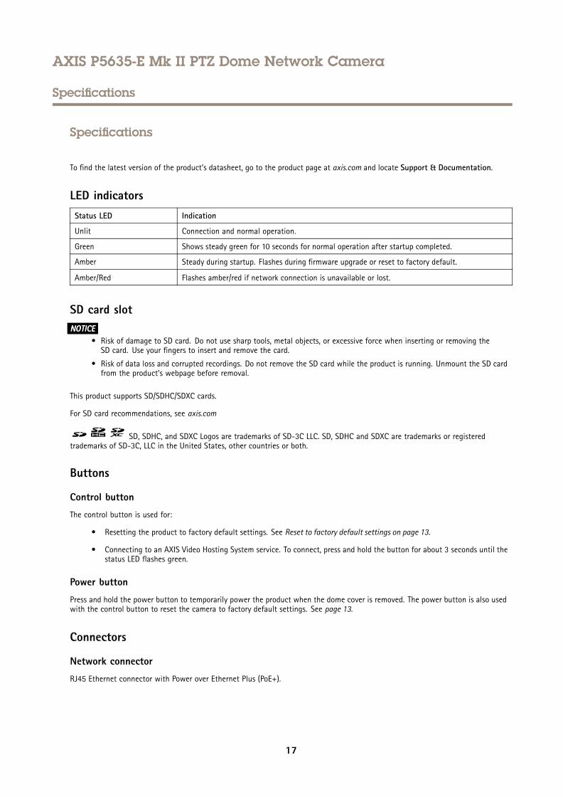
LED indicatorsStatus LED Indication
Unlit Connection and normal operation.
Green Shows steady green for 10 seconds for normal operation after startup completed.
Amber Steady during startup. Flashes during firmware upgrade or reset to factory default.
Amber/Red Flashes amber/red if network connection is unavailable or lost.
SD card slotNONONOTICETICETICE
• Risk of damage to SD card. Do not use sharp tools, metal objects, or excessive force when inserting or removing theSD card. Use your fingers to insert and remove the card.
• Risk of data loss and corrupted recordings. Do not remove the SD card while the product is running. Unmount the SD cardfrom the product’s webpage before removal.
This product supports SD/SDHC/SDXC cards.
For SD card recommendations, see axis.com
SD, SDHC, and SDXC Logos are trademarks of SD-3C LLC. SD, SDHC and SDXC are trademarks or registeredtrademarks of SD-3C, LLC in the United States, other countries or both.
Buttons
Control button
The control button is used for:
• Resetting the product to factory default settings. See Reset to factory default settings on page 13.
• Connecting to an AXIS Video Hosting System service. To connect, press and hold the button for about 3 seconds until thestatus LED flashes green.
Power button
Press and hold the power button to temporarily power the product when the dome cover is removed. The power button is also usedwith the control button to reset the camera to factory default settings. See page 13.
Connectors
Network connector
RJ45 Ethernet connector with Power over Ethernet Plus (PoE+).
17
AXIS P5635-E Mk II PTZ Dome Network Camera
Specifications
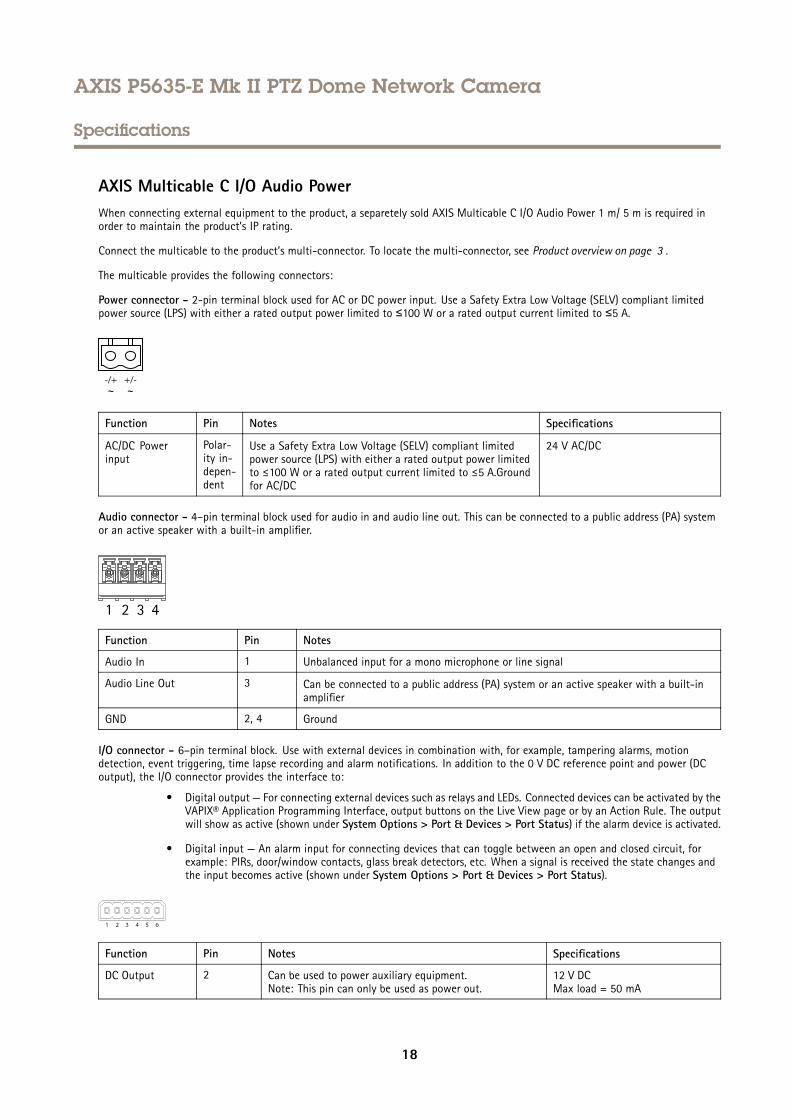
AXIS Multicable C I/O Audio PowerWhen connecting external equipment to the product, a separetely sold AXIS Multicable C I/O Audio Power 1 m/ 5 m is required inorder to maintain the product’s IP rating.
Connect the multicable to the product’s multi-connector. To locate the multi-connector, see Product overview on page 3 .
The multicable provides the following connectors:
Power connector - 2-pin terminal block used for AC or DC power input. Use a Safety Extra Low Voltage (SELV) compliant limitedpower source (LPS) with either a rated output power limited to ≤100 W or a rated output current limited to ≤5 A.
Function Pin Notes Specifications
AC/DC Powerinput
Polar-ity in-depen-dent
Use a Safety Extra Low Voltage (SELV) compliant limitedpower source (LPS) with either a rated output power limitedto ≤100 W or a rated output current limited to ≤5 A.Groundfor AC/DC
24 V AC/DC
Audio connector - 4–pin terminal block used for audio in and audio line out. This can be connected to a public address (PA) systemor an active speaker with a built-in amplifier.
Function Pin Notes
Audio In 1 Unbalanced input for a mono microphone or line signal
Audio Line Out 3 Can be connected to a public address (PA) system or an active speaker with a built-inamplifier
GND 2, 4 Ground
I/O connector - 6–pin terminal block. Use with external devices in combination with, for example, tampering alarms, motiondetection, event triggering, time lapse recording and alarm notifications. In addition to the 0 V DC reference point and power (DCoutput), the I/O connector provides the interface to:
• Digital output — For connecting external devices such as relays and LEDs. Connected devices can be activated by theVAPIX® Application Programming Interface, output buttons on the Live View page or by an Action Rule. The outputwill show as active (shown under System Options > Port & Devices > Port Status) if the alarm device is activated.
• Digital input — An alarm input for connecting devices that can toggle between an open and closed circuit, forexample: PIRs, door/window contacts, glass break detectors, etc. When a signal is received the state changes andthe input becomes active (shown under System Options > Port & Devices > Port Status).
Function Pin Notes Specifications
DC Output 2 Can be used to power auxiliary equipment.Note: This pin can only be used as power out.
12 V DCMax load = 50 mA
18
AXIS P5635-E Mk II PTZ Dome Network Camera
Specifications
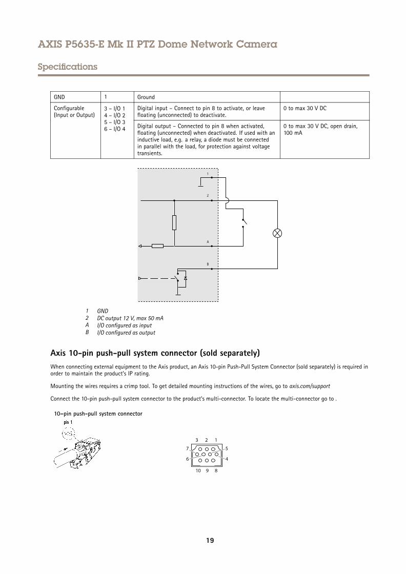
GND 1 Ground
Digital input – Connect to pin 8 to activate, or leavefloating (unconnected) to deactivate.
0 to max 30 V DCConfigurable(Input or Output)
3 – I/O 14 – I/O 25 – I/O 36 – I/O 4 Digital output – Connected to pin 8 when activated,
floating (unconnected) when deactivated. If used with aninductive load, e.g. a relay, a diode must be connectedin parallel with the load, for protection against voltagetransients.
0 to max 30 V DC, open drain,100 mA
1 GND2 DC output 12 V, max 50 mAA I/O configured as inputB I/O configured as output
Axis 10-pin push-pull system connector (sold separately)When connecting external equipment to the Axis product, an Axis 10-pin Push-Pull System Connector (sold separately) is required inorder to maintain the product’s IP rating.
Mounting the wires requires a crimp tool. To get detailed mounting instructions of the wires, go to axis.com/support
Connect the 10-pin push-pull system connector to the product’s multi-connector. To locate the multi-connector go to .
10–pin push-pull system connector
19
AXIS P5635-E Mk II PTZ Dome Network Camera
Specifications
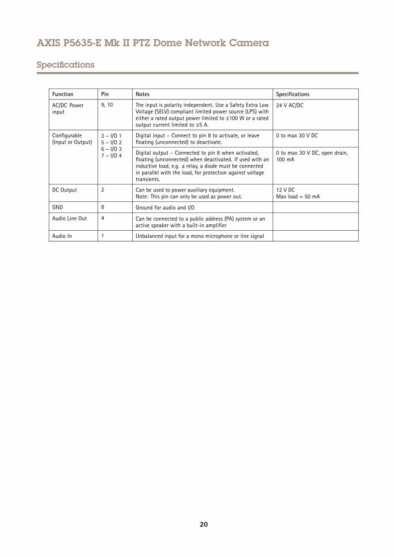
Function Pin Notes Specifications
AC/DC Powerinput
9, 10 The input is polarity independent. Use a Safety Extra LowVoltage (SELV) compliant limited power source (LPS) witheither a rated output power limited to ≤100 W or a ratedoutput current limited to ≤5 A.
24 V AC/DC
Digital input – Connect to pin 8 to activate, or leavefloating (unconnected) to deactivate.
0 to max 30 V DCConfigurable(Input or Output)
3 – I/O 15 – I/O 26 – I/O 37 – I/O 4 Digital output – Connected to pin 8 when activated,
floating (unconnected) when deactivated. If used with aninductive load, e.g. a relay, a diode must be connectedin parallel with the load, for protection against voltagetransients.
0 to max 30 V DC, open drain,100 mA
DC Output 2 Can be used to power auxiliary equipment.Note: This pin can only be used as power out.
12 V DCMax load = 50 mA
GND 8 Ground for audio and I/O
Audio Line Out 4 Can be connected to a public address (PA) system or anactive speaker with a built-in amplifier
Audio In 1 Unbalanced input for a mono microphone or line signal
20

User Manual Ver. M9.2AXIS P5635-E Mk II PTZ Dome Network Camera Date: April 2019© Axis Communications AB, 2016 - 2019 Part No. T10042850