Embed Size (px)
Citation preview
©2011-2013 Inter-CAD Kft.
All rights reserved.
User guide for
AxisVM rapido 2
The application was developed for rapid and simplified structural design. Using this application doesn’t mean
that the design engineer has lower responsibility in design. Users should always meet all design criteria and
follow design rules and current national design codes.

2 Rapido Beam 2
This page is intentionally left blank.
User guide v2r1 3
Contents
1. New Features of Rapido Beam 2 ....................................................................................................................................... 5
2. Using Rapido Beam .............................................................................................................................................................. 9
3. Project ................................................................................................................................................................................... 13
4. Material and Cross-section ............................................................................................................................................... 15
5. Structural model ................................................................................................................................................................. 19
6. Loads ..................................................................................................................................................................................... 21
7. Analysis and design ........................................................................................................................................................... 23
8. Report generation ............................................................................................................................................................... 27

4 Rapido Beam 2
This page is intentionally left blank.
User guide v2r1 5
1. New Features of Rapido Beam 2
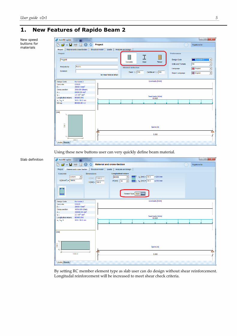
New speed buttons for materials
Using these new buttons user can very quickly define beam material.
Slab definition
By setting RC member element type as slab user can do design without shear reinforcement.
Longitudal reinforcement will be increased to meet shear check criteria.
6 Rapido Beam 2
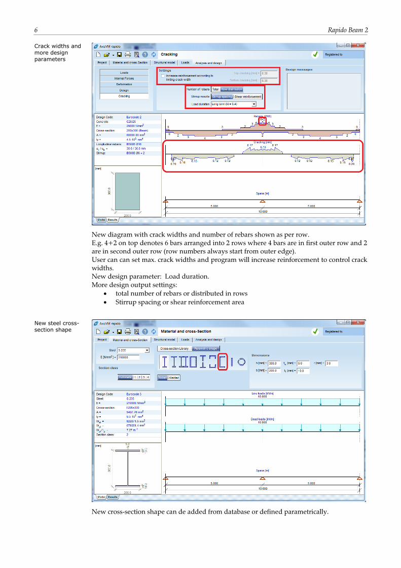
Crack widths and more design parameters
New diagram with crack widths and number of rebars shown as per row.
E.g. 4+2 on top denotes 6 bars arranged into 2 rows where 4 bars are in first outer row and 2
are in second outer row (row numbers always start from outer edge).
User can can set max. crack widths and program will increase reinforcement to control crack
widths.
New design parameter: Load duration.
More design output settings:
total number of rebars or distributed in rows
Stirrup spacing or shear reinforcement area
New steel cross-section shape
New cross-section shape can de added from database or defined parametrically.
User guide v2r1 7
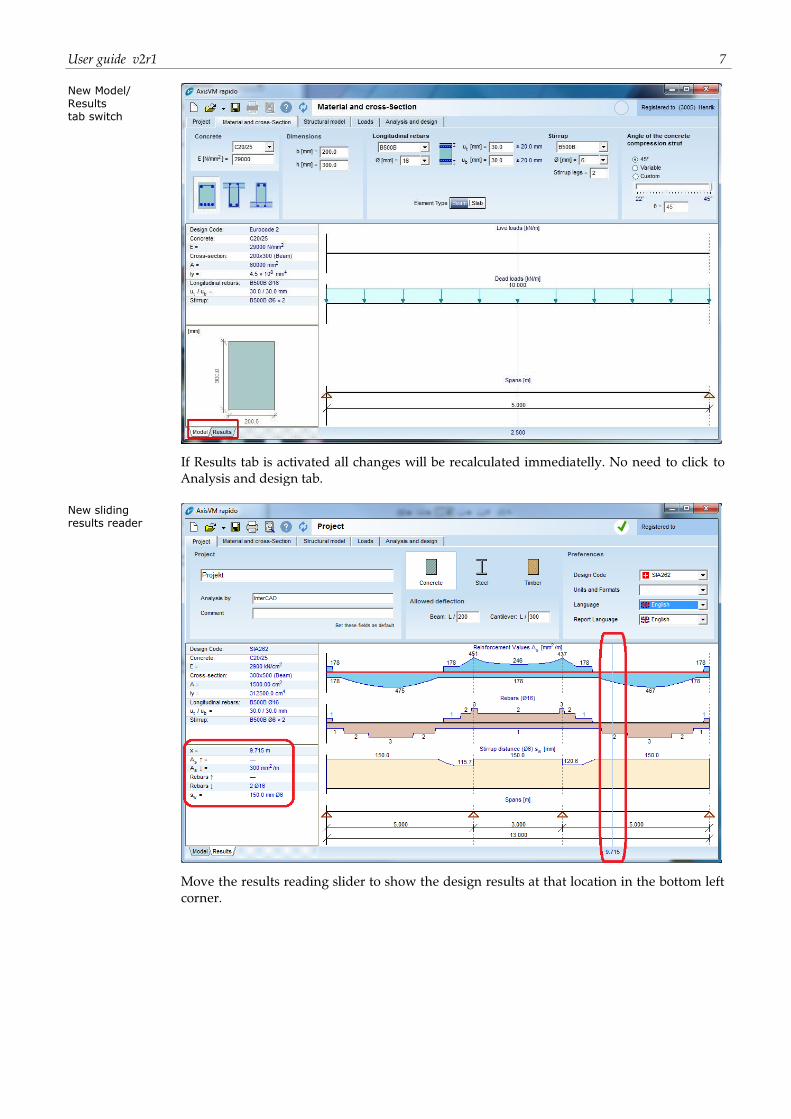
New Model/ Results tab switch
If Results tab is activated all changes will be recalculated immediatelly. No need to click to
Analysis and design tab.
New sliding results reader
Move the results reading slider to show the design results at that location in the bottom left
corner.

8 Rapido Beam 2
This page is intentionally left blank.
User guide v2r1 9
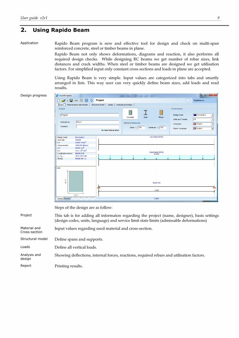
2. Using Rapido Beam
Application Rapido Beam program is new and effective tool for design and check on multi-span
reinforced concrete, steel or timber beams in plane.
Rapido Beam not only shows deformations, diagrams and reaction, it also performs all
required design checks. While designing RC beams we get number of rebar sizes, link
distances and crack widths. When steel or timber beams are designed we get utilisation
factors. For simplified input only constant cross sections and loads in plane are accepted.
Using Rapido Beam is very simple. Input values are categorized into tabs and smartly
arranged in lists. This way user can very quickly define beam sizes, add loads and read
results.
Design progress
Steps of the design are as follow:
Project This tab is for adding all informaton regarding the project (name, designer), basis settings
(design codes, units, language) and service limit state limits (admissable deformations)
Material and Cross-section
Input values regarding used material and cross-section.
Structural model Define spans and supports.
Loads Define all vertical loads.
Analysis and design
Showing deflections, internal forces, reactions, required rebars and utilisation factors.
Report Printing results.
10 Rapido Beam 2
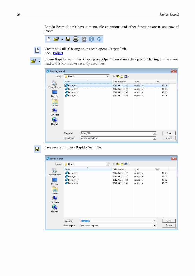
Rapido Beam doesn’t have a menu, file operations and other functions are in one row of
icons:
Create new file. Clicking on this icon opens „Project” tab.
See... Project
Opens Rapido Beam files. Clicking on „Open” icon shows dialog box. Clicking on the arrow
next to this icon shows recently used files.
Saves everything to a Rapido Beam file.
User guide v2r1 11
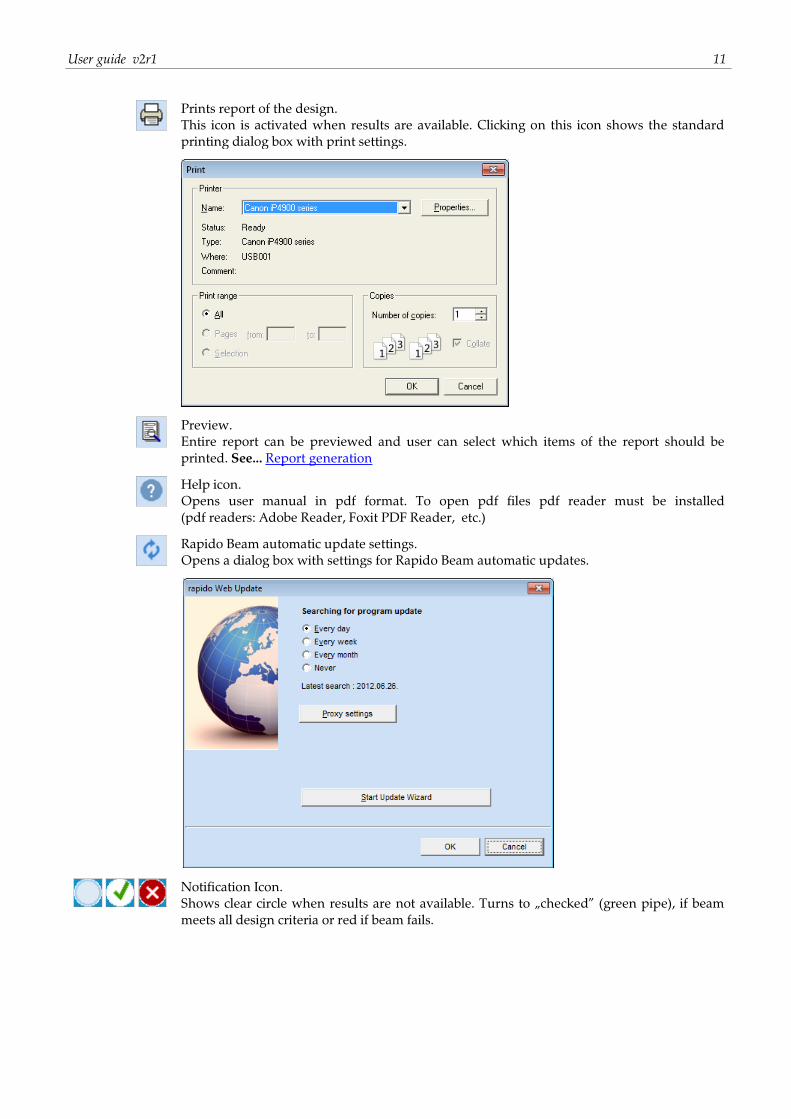
Prints report of the design.
This icon is activated when results are available. Clicking on this icon shows the standard
printing dialog box with print settings.
Preview.
Entire report can be previewed and user can select which items of the report should be
printed. See... Report generation
Help icon.
Opens user manual in pdf format. To open pdf files pdf reader must be installed
(pdf readers: Adobe Reader, Foxit PDF Reader, etc.)
Rapido Beam automatic update settings.
Opens a dialog box with settings for Rapido Beam automatic updates.
Notification Icon.
Shows clear circle when results are not available. Turns to „checked” (green pipe), if beam
meets all design criteria or red if beam fails.

12 Rapido Beam 2
This page is intentionally left blank.
User guide v2r1 13
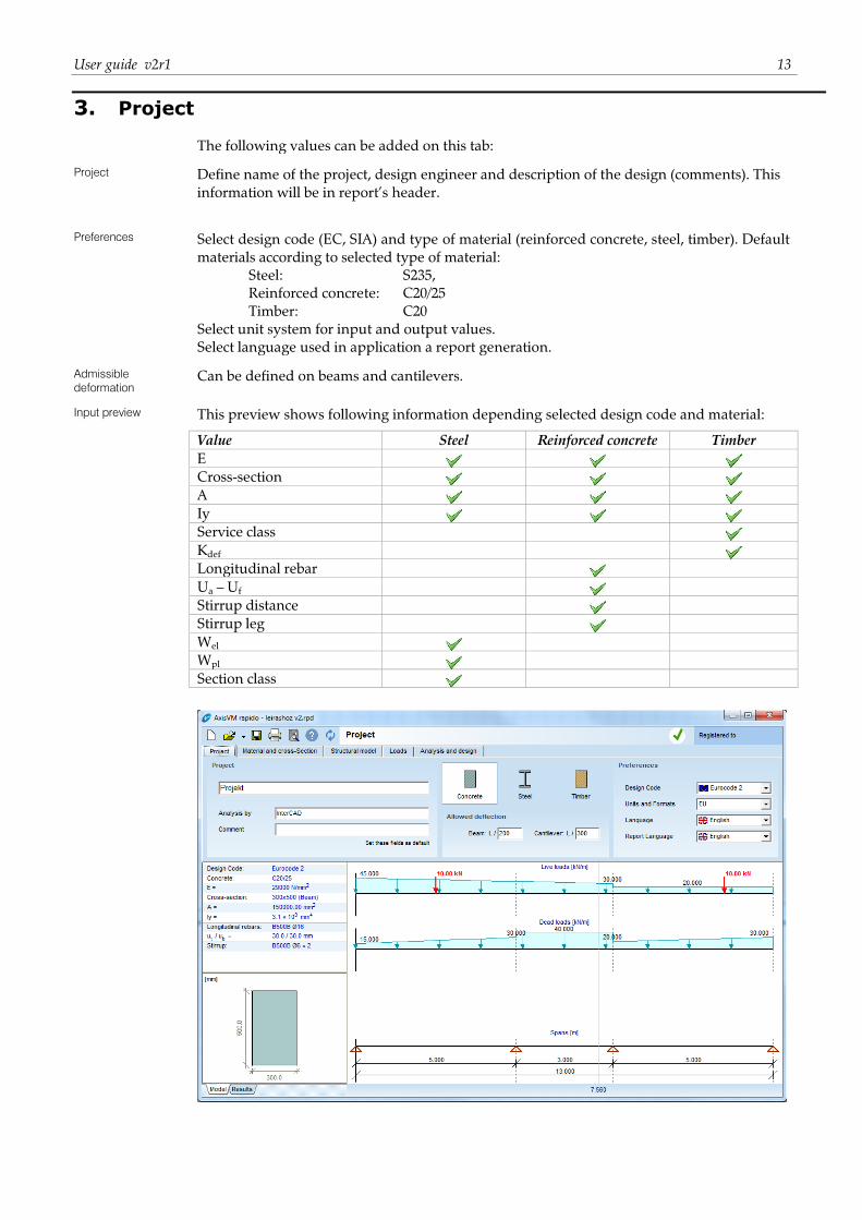
3. Project
The following values can be added on this tab:
Project Define name of the project, design engineer and description of the design (comments). This
information will be in report’s header.
Preferences Select design code (EC, SIA) and type of material (reinforced concrete, steel, timber). Default
materials according to selected type of material:
Steel: S235,
Reinforced concrete: C20/25
Timber: C20
Select unit system for input and output values.
Select language used in application a report generation.
Admissible
deformation
Can be defined on beams and cantilevers.
Input preview This preview shows following information depending selected design code and material:
Value Steel Reinforced concrete Timber
E
Cross-section
A
Iy
Service class
Kdef Longitudinal rebar
Ua – Uf
Stirrup distance
Stirrup leg
Wel
Wpl
Section class

14 Rapido Beam 2
This page is intentionally left blank.
User guide v2r1 15
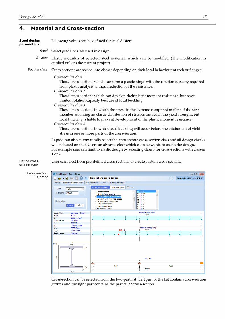
4. Material and Cross-section
Steel design parameters
Following values can be defined for steel design:
Steel Select grade of steel used in design.
E value Elastic modulus of selected steel material, which can be modified (The modification is
applied only to the current project)
Section class Cross-sections are sorted into classes depending on their local behaviour of web or flanges:
Cross-section class 1
Those cross-sections which can form a plastic hinge with the rotation capacity required
from plastic analysis without reduction of the resistance.
Cross-section class 2
Those cross-sections which can develop their plastic moment resistance, but have
limited rotation capacity because of local buckling.
Cross-section class 3
Those cross-sections in which the stress in the extreme compression fibre of the steel
member assuming an elastic distribution of stresses can reach the yield strength, but
local buckling is liable to prevent development of the plastic moment resistance.
Cross-section class 4
Those cross-sections in which local buckling will occur before the attainment of yield
stress in one or more parts of the cross-section.
Rapido can also automatically select the appropriate cross-section class and all design checks
will be based on that. User can always select which class he wants to use in the design.
For example user can limit to elastic design by selecting class 3 for cross-sections with classes
1 or 2.
Define cross-section type
User can select from pre-defined cross-sections or create custom cross-section.
Cross-section Library
Cross-section can be selected from the two-part list. Left part of the list contains cross-section
groups and the right part contains the particular cross-section.
16 Rapido Beam 2
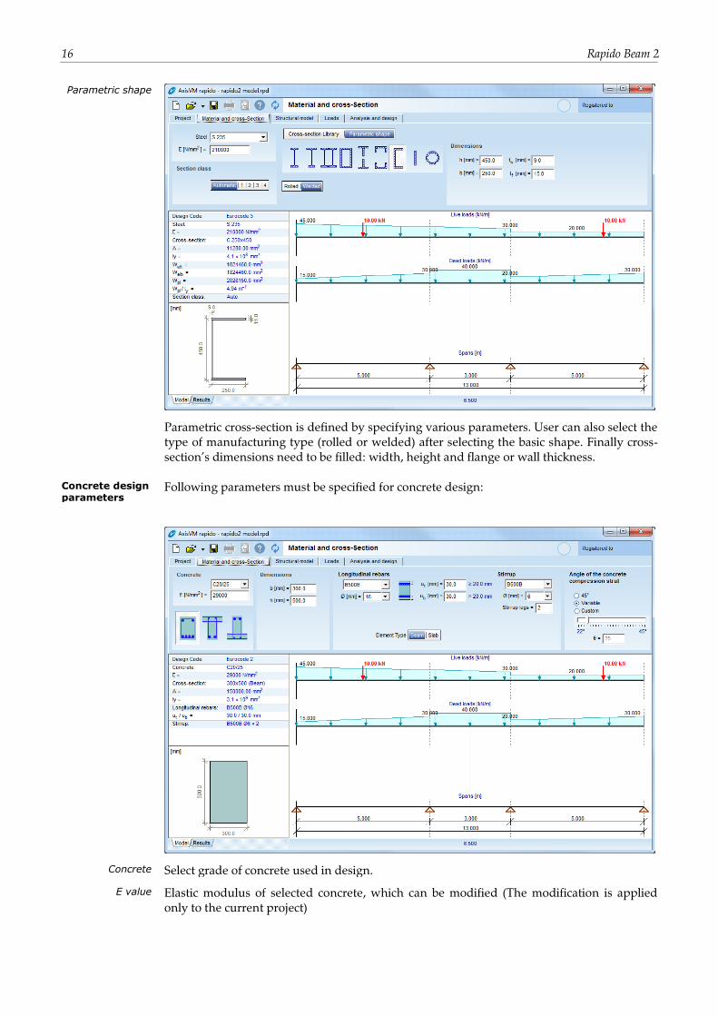
Parametric shape
Parametric cross-section is defined by specifying various parameters. User can also select the
type of manufacturing type (rolled or welded) after selecting the basic shape. Finally cross-
section’s dimensions need to be filled: width, height and flange or wall thickness.
Concrete design parameters
Following parameters must be specified for concrete design:
Concrete Select grade of concrete used in design.
E value Elastic modulus of selected concrete, which can be modified (The modification is applied
only to the current project)
User guide v2r1 17
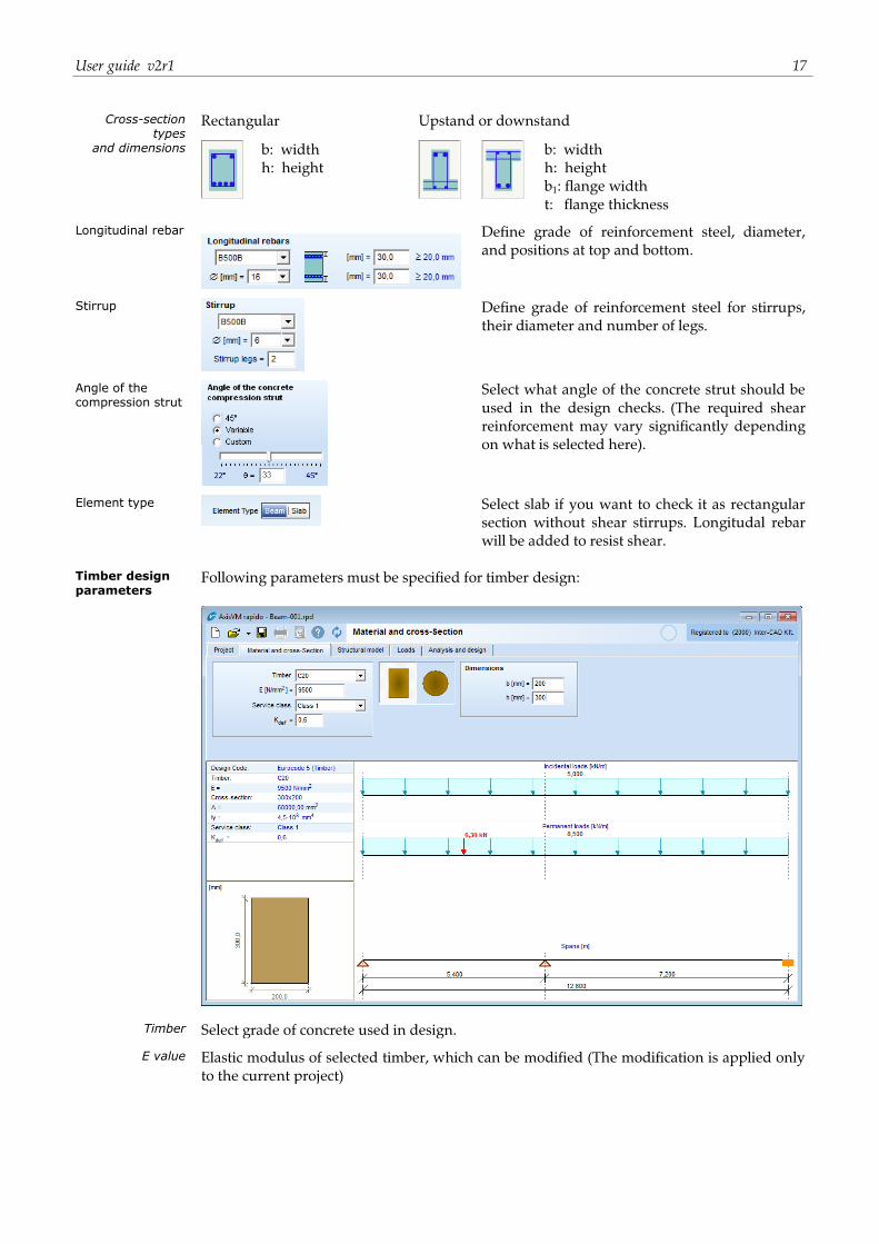
Cross-section types
Rectangular Upstand or downstand
and dimensions
b: width
h: height
b: width
h: height
b1: flange width
t: flange thickness
Longitudinal rebar
Define grade of reinforcement steel, diameter,
and positions at top and bottom.
Stirrup
Define grade of reinforcement steel for stirrups,
their diameter and number of legs.
Angle of the compression strut
Select what angle of the concrete strut should be
used in the design checks. (The required shear
reinforcement may vary significantly depending
on what is selected here).
Element type
Select slab if you want to check it as rectangular
section without shear stirrups. Longitudal rebar
will be added to resist shear.
Timber design parameters
Following parameters must be specified for timber design:
Timber Select grade of concrete used in design.
E value Elastic modulus of selected timber, which can be modified (The modification is applied only
to the current project)
18 Rapido Beam 2
Service class Timber members should be assigned to one of these service classes.
Service classes for timber members are as follow(EN 1995-1-1, 2.3.1.3):
Service class 1 is characterised by a moisture content in the materials corresponding to a
temperature of 20 C and the relative humidity of the surrounding air only exceeding 65%
for a few weeks per year.
Service class 2 is characterised by a moisture content in the materials corresponding to a
temperature of 20 C and the relative humidity of the surrounding air only exceeding 85%
for a few weeks per year.
Service class 3 is characterised by climatic conditions leading to higher moisture contents
than in service class 2.
kdef kdef factor is automatically set based on timber type and service class. (Table 3.2, EN 1995-1-1).
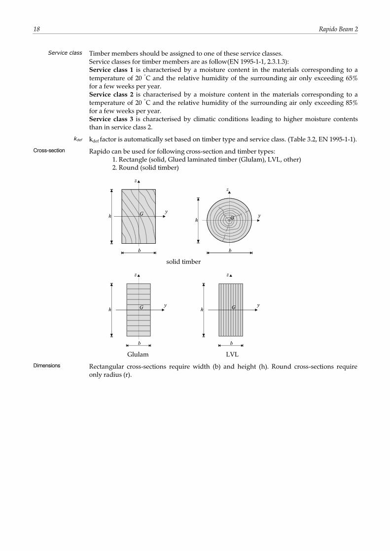
Cross-section Rapido can be used for following cross-section and timber types:
1. Rectangle (solid, Glued laminated timber (Glulam), LVL, other)
2. Round (solid timber)
solid timber
Glulam LVL
Dimensions Rectangular cross-sections require width (b) and height (h). Round cross-sections require
only radius (r).
User guide v2r1 19
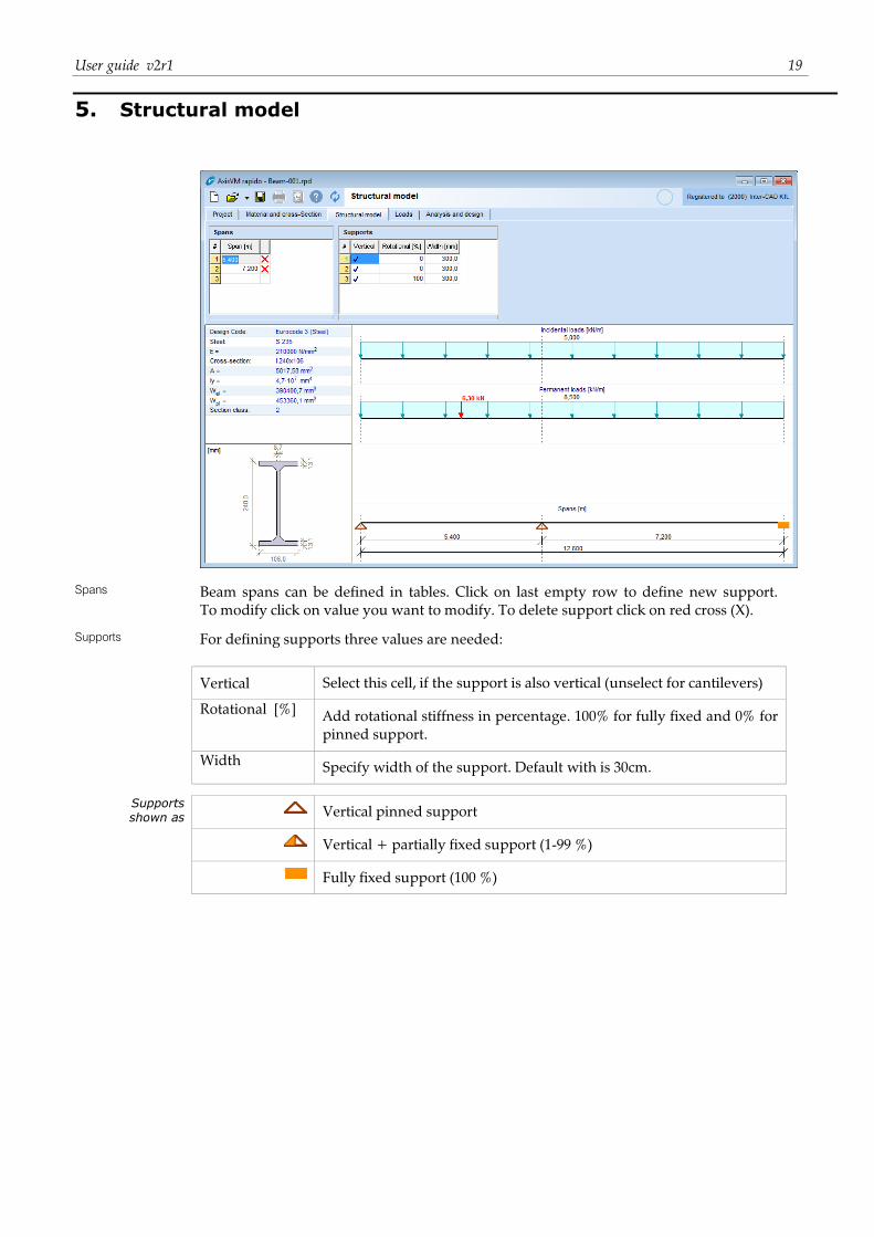
5. Structural model
Spans Beam spans can be defined in tables. Click on last empty row to define new support.
To modify click on value you want to modify. To delete support click on red cross (X).
Supports For defining supports three values are needed:
Vertical Select this cell, if the support is also vertical (unselect for cantilevers)
Rotational [%] Add rotational stiffness in percentage. 100% for fully fixed and 0% for
pinned support.
Width Specify width of the support. Default with is 30cm.
Supports shown as
Vertical pinned support
Vertical + partially fixed support (1-99 %)
Fully fixed support (100 %)

20 Rapido Beam 2
This page is intentionally left blank.
User guide v2r1 21
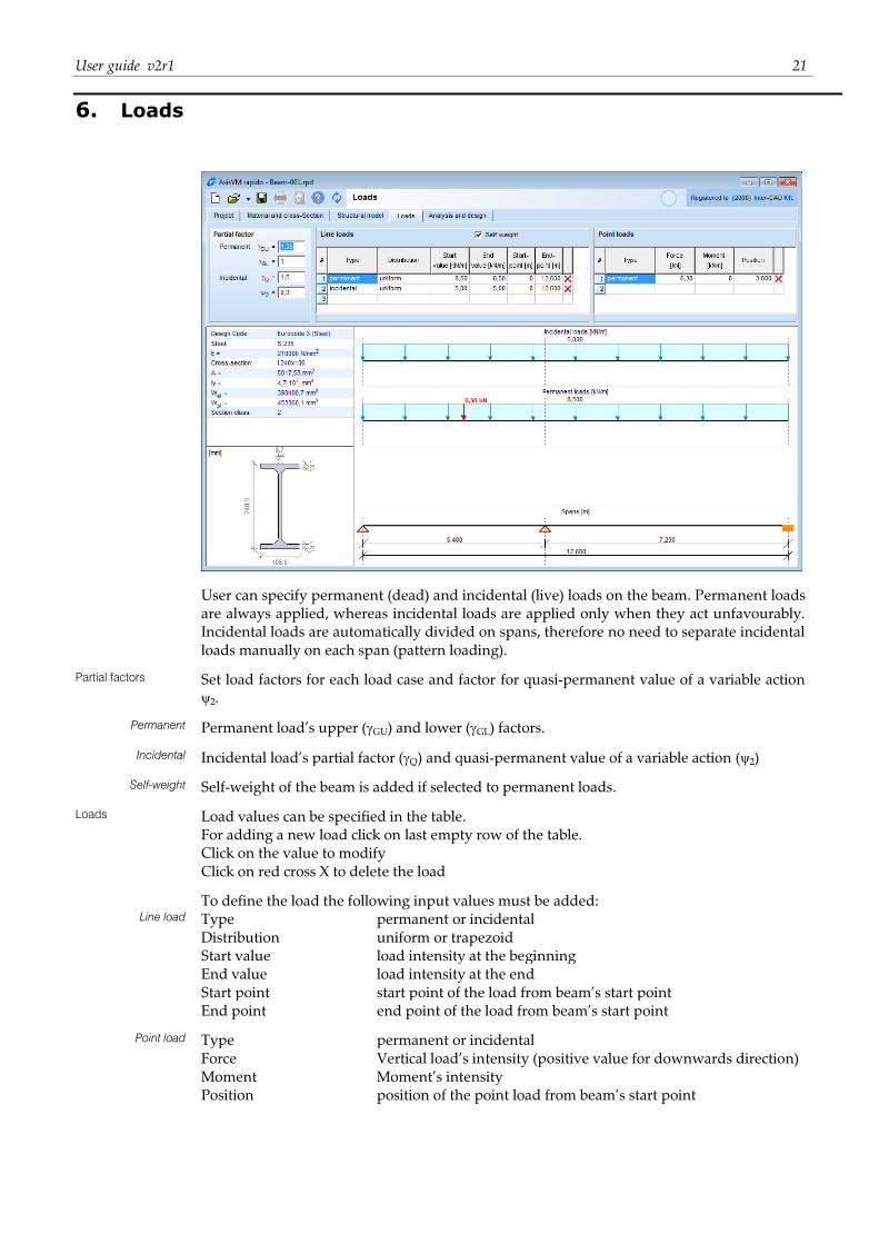
6. Loads
User can specify permanent (dead) and incidental (live) loads on the beam. Permanent loads
are always applied, whereas incidental loads are applied only when they act unfavourably.
Incidental loads are automatically divided on spans, therefore no need to separate incidental
loads manually on each span (pattern loading).
Partial factors Set load factors for each load case and factor for quasi-permanent value of a variable action
ψ2.
Permanent Permanent load’s upper (GU) and lower (GL) factors.
Incidental Incidental load’s partial factor (Q) and quasi-permanent value of a variable action (ψ2)
Self-weight Self-weight of the beam is added if selected to permanent loads.
Loads Load values can be specified in the table.
For adding a new load click on last empty row of the table.
Click on the value to modify
Click on red cross X to delete the load
To define the load the following input values must be added:
Line load Type permanent or incidental
Distribution uniform or trapezoid
Start value load intensity at the beginning
End value load intensity at the end
Start point start point of the load from beam’s start point
End point end point of the load from beam’s start point
Point load Type permanent or incidental
Force Vertical load’s intensity (positive value for downwards direction)
Moment Moment’s intensity
Position position of the point load from beam’s start point

22 Rapido Beam 2
This page is intentionally left blank.
User guide v2r1 23
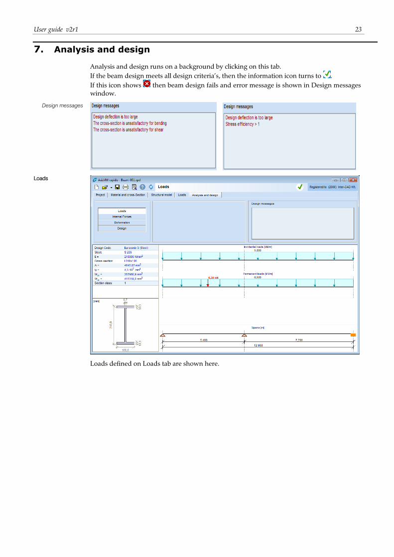
7. Analysis and design
Analysis and design runs on a background by clicking on this tab.
If the beam design meets all design criteria’s, then the information icon turns to .
If this icon shows then beam design fails and error message is shown in Design messages
window.
Design messages
Loads
Loads defined on Loads tab are shown here.
24 Rapido Beam 2
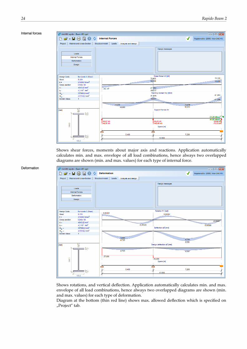
Internal forces
Shows shear forces, moments about major axis and reactions. Application automatically
calculates min. and max. envelope of all load combinations, hence always two overlapped
diagrams are shown (min. and max. values) for each type of internal force.
Deformation
Shows rotations, and vertical deflection. Application automatically calculates min. and max.
envelope of all load combinations, hence always two overlapped diagrams are shown (min.
and max. values) for each type of deformation.
Diagram at the bottom (thin red line) shows max. allowed deflection which is specified on
„Project“ tab.
User guide v2r1 25
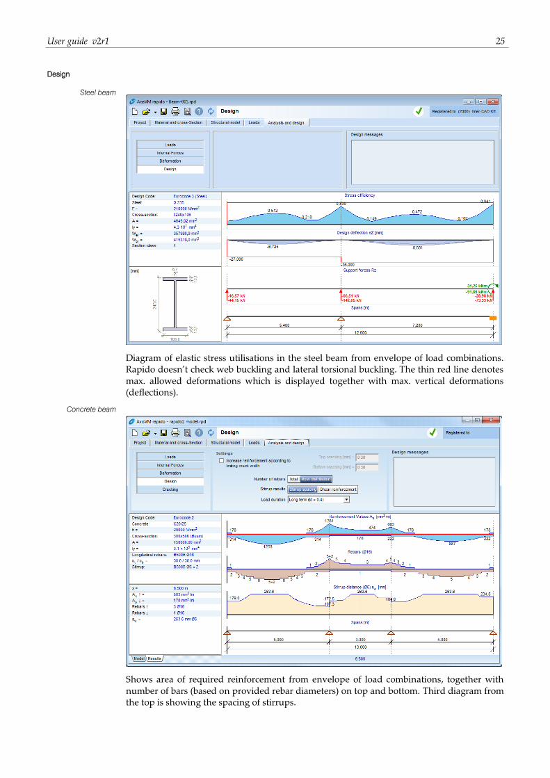
Design
Steel beam
Diagram of elastic stress utilisations in the steel beam from envelope of load combinations.
Rapido doesn’t check web buckling and lateral torsional buckling. The thin red line denotes
max. allowed deformations which is displayed together with max. vertical deformations
(deflections).
Concrete beam
Shows area of required reinforcement from envelope of load combinations, together with
number of bars (based on provided rebar diameters) on top and bottom. Third diagram from
the top is showing the spacing of stirrups.
26 Rapido Beam 2
Increase
reinforcement
according to limiting
crack width
If you check this option you can define max. crack width at top and bottom and rebar will
be added to meet this criteria.
Number of rebars Show total numbers of bars or bars per row separated with + sign. e.g: 5+2=7 bars, 5 in frst
row and 2 in second row.
Stirrup results Show spacing of defined stirrups or required area of shear reinforcement.
Load duration Load duration used for crack width calculations, See formula 7.3.4.(2) in Eurocode. (only for
Eurocode)
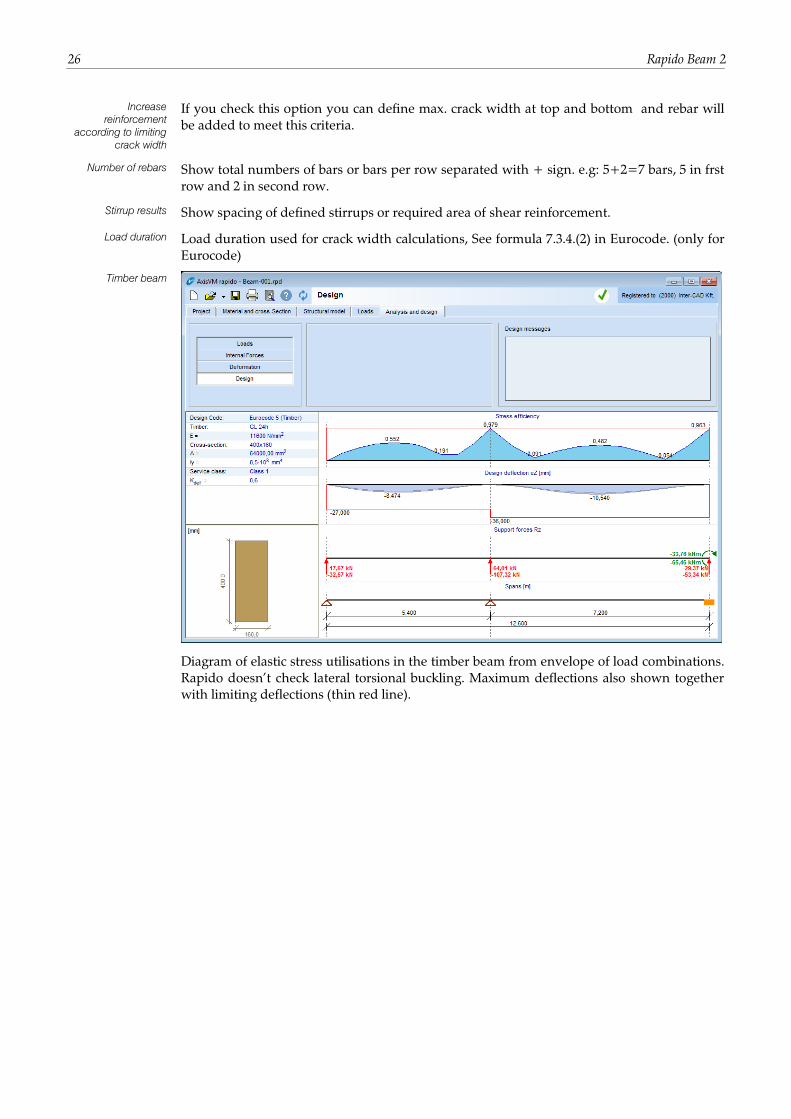
Timber beam
Diagram of elastic stress utilisations in the timber beam from envelope of load combinations.
Rapido doesn’t check lateral torsional buckling. Maximum deflections also shown together
with limiting deflections (thin red line).
User guide v2r1 27
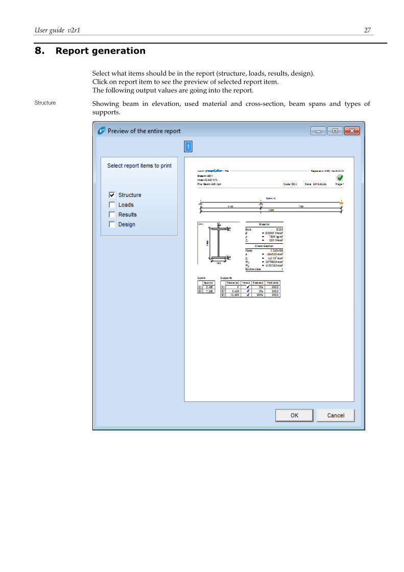
8. Report generation
Select what items should be in the report (structure, loads, results, design).
Click on report item to see the preview of selected report item.
The following output values are going into the report.
Structure Showing beam in elevation, used material and cross-section, beam spans and types of
supports.
28 Rapido Beam 2
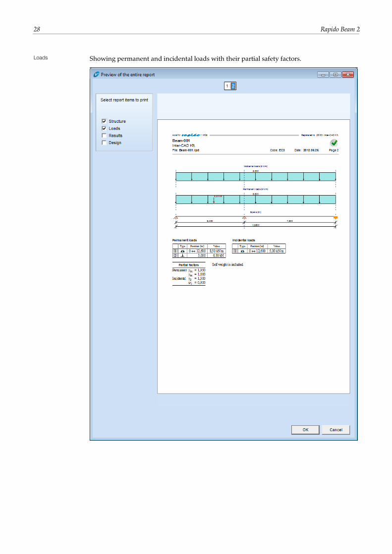
Loads Showing permanent and incidental loads with their partial safety factors.
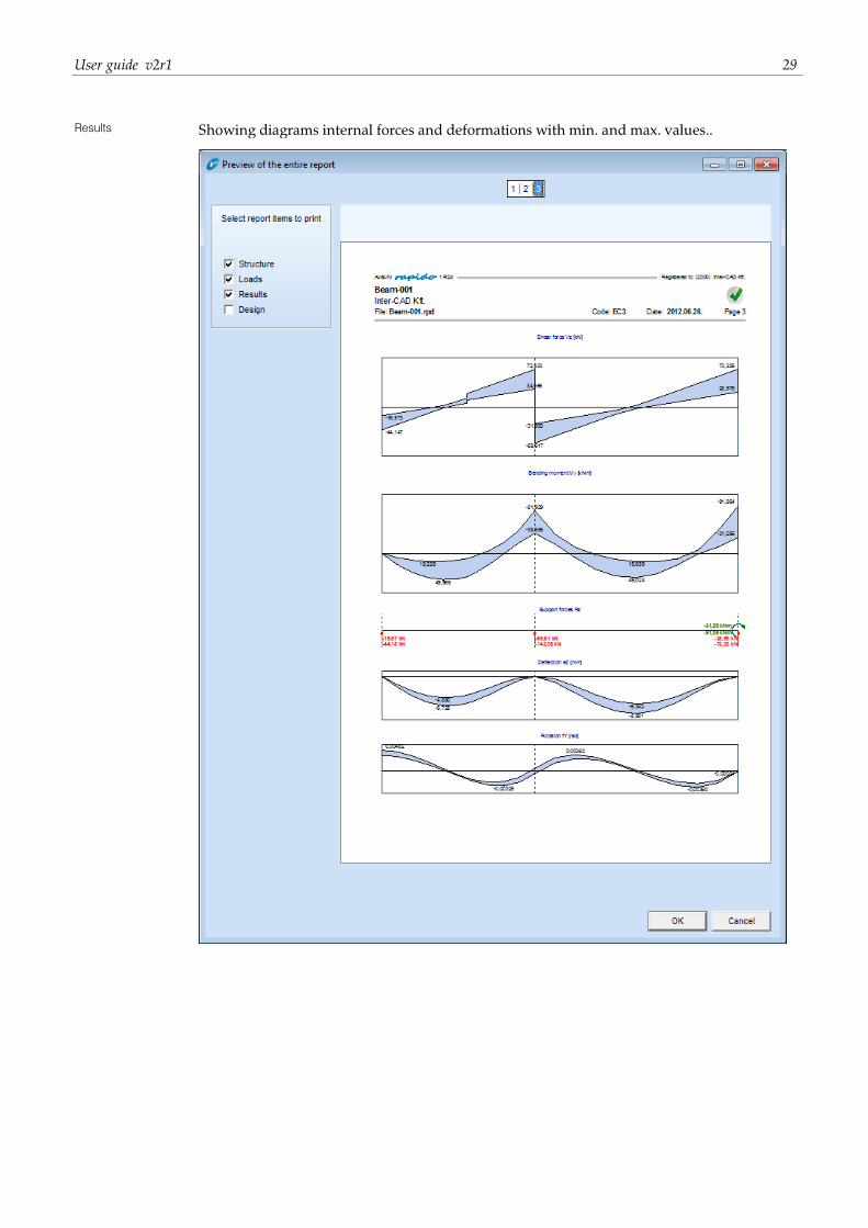
User guide v2r1 29
Results Showing diagrams internal forces and deformations with min. and max. values..
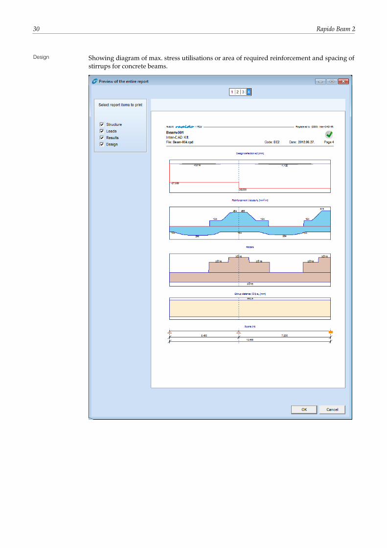
30 Rapido Beam 2
Design Showing diagram of max. stress utilisations or area of required reinforcement and spacing of
stirrups for concrete beams.

User guide v2r1 31
Notes