Embed Size (px)
Citation preview

B. Maidl, M. Herrenknecht, U. Maidl, G. Wehrmeyer
Mechanised Shield Tunnelling

2nd Edition
Mechanised Shield Tunnelling
Bernhard MaidlMartin HerrenknechtUlrich MaidlGerhard Wehrmeyer
Prof. Dr.-Ing. Bernhard Maidl Dr.-Ing. E.h. Martin Herrenknechtmtc – Maidl Tunnelconsultants GmbH & Co. KG Herrenknecht AGFuldastr. 11 Schlehenweg 247051 Duisburg 77963 Schwanau
Dr.-Ing. Ulrich Maidl Dr.-Ing. Gerhard Wehrmeyermtc – Maidl Tunnelconsultants GmbH & Co. KG Herrenknecht AGFuldastr. 11 Schlehenweg 247051 Duisburg 77963 Schwanau
Translated by David Sturge, Kirchbach, Germany
Cover: Herrenknecht-EPB-Shield S-300 Madrid M-30 By-Pass Sue Túnel Norte, Madrid, Spain
Photo: Herrenknecht AG
Library of Congress Card No.: applied for
British Library Cataloguing-in-Publication DataA catalogue record for this book is available from the British Library.
Bibliographic information published bythe Deutsche NationalbibliothekThe Deutsche Nationalbibliothek lists this publication in the Deutsche Nationalbibliografie; detailed bibliographic data are available on the Internet at <http://dnb.d-nb.de>.
© 2012 Wilhelm Ernst & Sohn, Verlag für Architektur und technische Wissenschaften GmbH & Co. KG, Rotherstr. 21, 10245 Berlin, Germany
All rights reserved (including those of translation into other languages). No part of this book may be reproduced in any form – by photoprinting, microfilm, or any other means – nor transmitted or translated into a machine language without written permission from the publishers. Registered names, trademarks, etc. used in this book, even when not specifically marked as such, are not to be considered unprotected by law.
Coverdesign: Sonja Frank, Berlin, GermanyProduktion management: pp030 – Produktionsbüro Heike Praetor, BerlinTypesetting: Reemers Publishing Services GmbH, KrefeldPrinting and Binding: Strauss GmbH, Mörlenbach
Printed in the Federal Republic of Germany.Printed on acid-free paper.
2nd EditionPrint ISBN: 978-3-433-02995-4ePDF ISBN: 978-3-433-60150-1ePub ISBN: 978-3-433-60149-5mobi ISBN: 978-3-433-60148-8o-Book ISBN: 978-3-433-60105-1

„A plan whatever it may be must be made for the bad ground, it must be calculated to meet all exigencies, all disasters and to overcome them after they have occured.“
Marc Isambard Brunel on suggested improvements after the flooding of the Thames Tunnel in 1831.

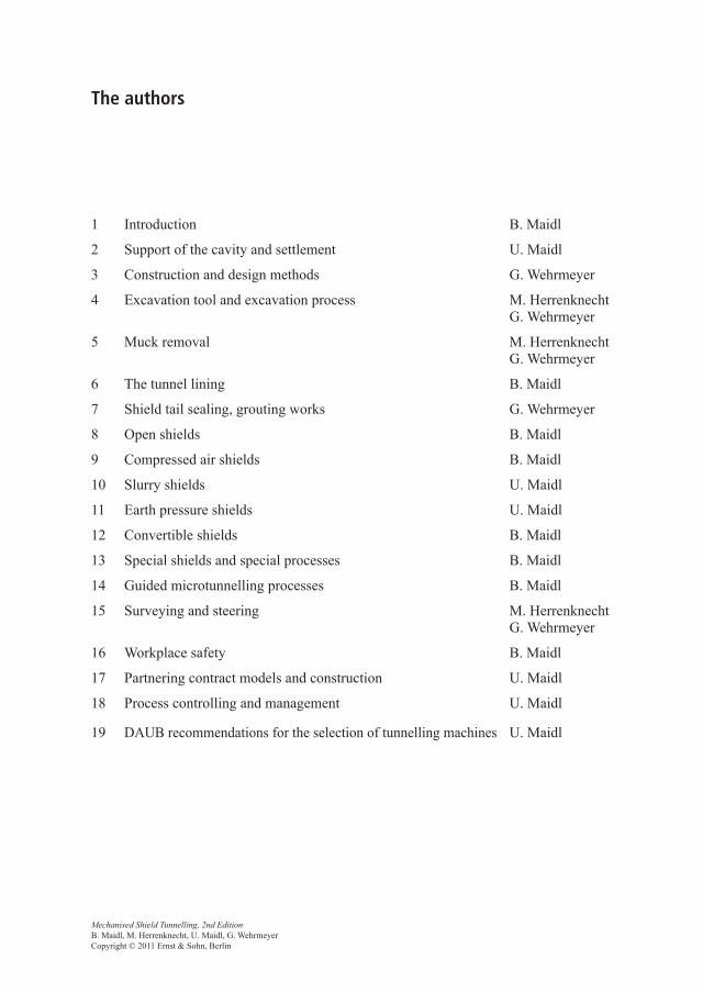
The authors
1 Introduction B. Maidl
2 Support of the cavity and settlement U. Maidl
3 Construction and design methods G. Wehrmeyer
4 Excavation tool and excavation process M. Herrenknecht G. Wehrmeyer
5 Muck removal M. Herrenknecht G. Wehrmeyer
6 The tunnel lining B. Maidl
7 Shield tail sealing, grouting works G. Wehrmeyer
8 Open shields B. Maidl
9 Compressed air shields B. Maidl
10 Slurry shields U. Maidl
11 Earth pressure shields U. Maidl
12 Convertible shields B. Maidl
13 Special shields and special processes B. Maidl
14 Guided microtunnelling processes B. Maidl
15 Surveying and steering M. Herrenknecht G. Wehrmeyer
16 Workplace safety B. Maidl
17 Partnering contract models and construction U. Maidl
18 Process controlling and management U. Maidl
19 DAUB recommendations for the selection of tunnelling machines U. Maidl
Mechanised Shield Tunnelling, 2nd Edition B. Maidl, M. Herrenknecht, U. Maidl, G. WehrmeyerCopyright © 2011 Ernst & Sohn, Berlin

Foreword to the 2nd Edition
The rapid progress of mechanised tunnelling to market leadership has continued – even exceeded predictions; the general worldwide trend in construction towards mechanisation and automation clearly demanded a similar development in tunnelling. It is significant that even in Austria, the traditional home of the New Austrian Tunnelling Method (NATM), mechanised tunnelling has also established its position in the last decade. Occupational health and safety, faster advance rates, improved cost security and labour-saving opened opportunities for mechanised tunnelling on a few major projects – normally in competi-tion with conventional construction methods.
So it is appropriate that this book should now be revised, 20 years after its first publica-tion. The extent of innovations and practical experience led to a complete reworking. Inci-dentally, the book “Hardock Tunnel Boring Machines“, which appeared in 2008, already offered access to the newest technology in the area of tunnel support. The team of authors has adapted the content to the latest technology and has been supplemented to provide the necessary specialist knowledge.
The original authors B. Maidl and M. Herrenknecht also worked on this edition. We have gained my son Dr.-Ing. U. Maidl and my former doctoral candidate Dr.-Ing. G. Wehrmeyer, who have particularly devoted themselves to new developments.
I am very thankful that I could still rely on the help of my former employees Herr H. Schmidt and Herr G. Kaufhold for the new revision. I would like to thank Herr Dipl-Ing. M. Griese from MTC, who helped a great deal with the detailed work and overall coordi-nation. I would also like to thank my grandson Max Maidl for his assistance. A thank-you to all, especially the author colleagues and the publisher.
Bochum, January 2011 Bernhard Maidl
Mechanised Shield Tunnelling, 2nd Edition B. Maidl, M. Herrenknecht, U. Maidl, G. WehrmeyerCopyright © 2011 Ernst & Sohn, Berlin

Table of Contents
The authors . . . . . . . . . . . . . . . . . . . . . . . . . . . . . . . . . . . . . . . . . . . . . . . . . . . . . . . . . . VII
Foreword to the 2nd Edition . . . . . . . . . . . . . . . . . . . . . . . . . . . . . . . . . . . . . . . . . . . . IX
1 Introduction . . . . . . . . . . . . . . . . . . . . . . . . . . . . . . . . . . . . . . . . . . . . . . . . . . . . 11.1 Basic principles and terms . . . . . . . . . . . . . . . . . . . . . . . . . . . . . . . . . . . . . . . . . 31.2 Types of tunnel boring machine according to DAUB . . . . . . . . . . . . . . . . . . . . 5
1.2.1 Categories of tunnelling machines German association for underground construction (TVM) . . . . . . . . . . . . . . . . . . . . . . . . . . . 5
1.2.2 Tunnel boring machines (TBM) . . . . . . . . . . . . . . . . . . . . . . . . . . . . 61.2.2.1 Tunnel boring machines without shield (gripper TBM) . . . . . . . . . . 61.2.2.2 Reamer tunnel boring machines (ETBM) . . . . . . . . . . . . . . . . . . . . . 71.2.2.3 Tunnel boring machines with single shield (TBM-S) . . . . . . . . . . . . 71.2.3 Double shield machines (DSM) . . . . . . . . . . . . . . . . . . . . . . . . . . . . 71.2.4 Shield machines (SM) . . . . . . . . . . . . . . . . . . . . . . . . . . . . . . . . . . . . 81.2.4.1 Shield machines with full-face excavation (SM-V) . . . . . . . . . . . . . 81.2.4.2 Shield machines with partial face excavation (SM-T) . . . . . . . . . . . 111.2.5 Adaptable shield machines with combined process technology
(KSM) . . . . . . . . . . . . . . . . . . . . . . . . . . . . . . . . . . . . . . . . . . . . . . . . 111.2.6 Special types . . . . . . . . . . . . . . . . . . . . . . . . . . . . . . . . . . . . . . . . . . . 121.2.6.1 Blade shields . . . . . . . . . . . . . . . . . . . . . . . . . . . . . . . . . . . . . . . . . . . 121.2.6.2 Shields with multiple circular cross-sections . . . . . . . . . . . . . . . . . . 121.2.6.3 Articulated shields . . . . . . . . . . . . . . . . . . . . . . . . . . . . . . . . . . . . . . . 121.2.7 Remarks about the individual types of tunnelling machines
with diagrams . . . . . . . . . . . . . . . . . . . . . . . . . . . . . . . . . . . . . . . . . . 121.2.7.1 Tunnel boring machines (TBM) . . . . . . . . . . . . . . . . . . . . . . . . . . . . 121.2.7.2 Double shield machines (DSM) . . . . . . . . . . . . . . . . . . . . . . . . . . . . 131.2.7.3 Face without support (SM-V1) . . . . . . . . . . . . . . . . . . . . . . . . . . . . . 131.2.7.4 Face with mechanical support (SM-V2) . . . . . . . . . . . . . . . . . . . . . . 141.2.7.5 Face with compressed air (SM-V3). . . . . . . . . . . . . . . . . . . . . . . . . . 141.2.7.6 Face with slurry support (SM-V4). . . . . . . . . . . . . . . . . . . . . . . . . . . 141.2.7.7 Face with earth pressure support (SM-V5) . . . . . . . . . . . . . . . . . . . . 141.2.7.8 Face without support (SM-T1) . . . . . . . . . . . . . . . . . . . . . . . . . . . . . 151.2.7.9 Face with partial support (SM-T2) . . . . . . . . . . . . . . . . . . . . . . . . . . 151.2.7.10 Face with compressed air support (SM-T3) . . . . . . . . . . . . . . . . . . . 151.2.7.11 Face with slurry support (SM-T4) . . . . . . . . . . . . . . . . . . . . . . . . . . . 161.2.7.12 Adaptable machines (KSM) . . . . . . . . . . . . . . . . . . . . . . . . . . . . . . . 16
1.3 Origins and historical developments . . . . . . . . . . . . . . . . . . . . . . . . . . . . . . . . . 16
2 Support of the cavity and settlement . . . . . . . . . . . . . . . . . . . . . . . . . . . . . . . 252.1 Support of the face . . . . . . . . . . . . . . . . . . . . . . . . . . . . . . . . . . . . . . . . . . . . . . . 25
2.1.1 Natural support . . . . . . . . . . . . . . . . . . . . . . . . . . . . . . . . . . . . . . . . . 252.1.2 Mechanical support . . . . . . . . . . . . . . . . . . . . . . . . . . . . . . . . . . . . . . 26
Mechanised Shield Tunnelling, 2nd Edition B. Maidl, M. Herrenknecht, U. Maidl, G. WehrmeyerCopyright © 2011 Ernst & Sohn, Berlin
XII Table of Contents
2.1.3 Compressed air support . . . . . . . . . . . . . . . . . . . . . . . . . . . . . . . . . . . 262.1.4 Slurry support . . . . . . . . . . . . . . . . . . . . . . . . . . . . . . . . . . . . . . . . . . 282.1.5 Earth support . . . . . . . . . . . . . . . . . . . . . . . . . . . . . . . . . . . . . . . . . . . 322.1.6 Calculation models . . . . . . . . . . . . . . . . . . . . . . . . . . . . . . . . . . . . . . 32
2.2 Support of the cavity at the shield . . . . . . . . . . . . . . . . . . . . . . . . . . . . . . . . . . . 372.3 Support of the cavity behind the shield . . . . . . . . . . . . . . . . . . . . . . . . . . . . . . . 372.4 Settlement and damage classifications . . . . . . . . . . . . . . . . . . . . . . . . . . . . . . . . 39
2.4.1 Empirical determination of the settlement. . . . . . . . . . . . . . . . . . . . . 412.4.2 Numerical models for the calculation of settlement . . . . . . . . . . . . . 43
2.5 Heave and compaction . . . . . . . . . . . . . . . . . . . . . . . . . . . . . . . . . . . . . . . . . . . . 46
3 Design and calculation methods. . . . . . . . . . . . . . . . . . . . . . . . . . . . . . . . . . . . 473.1 Constructional parts of the shield . . . . . . . . . . . . . . . . . . . . . . . . . . . . . . . . . . . . 473.2 Loading on the shield . . . . . . . . . . . . . . . . . . . . . . . . . . . . . . . . . . . . . . . . . . . . . 50
3.2.1 Loading on the shield skin. . . . . . . . . . . . . . . . . . . . . . . . . . . . . . . . . 513.2.2 Loading on the pressure bulkhead . . . . . . . . . . . . . . . . . . . . . . . . . . . 533.2.3 Loading from the thrust cylinders . . . . . . . . . . . . . . . . . . . . . . . . . . . 54
3.3 Calculation of the necessary thrust force . . . . . . . . . . . . . . . . . . . . . . . . . . . . . . 543.3.1 Resistance to advance through friction on the shield skin. . . . . . . . . 553.3.2 Resistance to advance at the front shield. . . . . . . . . . . . . . . . . . . . . . 563.3.3 Resistance to advance at the face through platforms and
excavation tools . . . . . . . . . . . . . . . . . . . . . . . . . . . . . . . . . . . . . . . . . 573.3.4 Resistance to advance with slurry support, earth support and
compressed air support . . . . . . . . . . . . . . . . . . . . . . . . . . . . . . . . . . . 583.3.5 Resistance to advance from steering the shield . . . . . . . . . . . . . . . . . 583.3.6 Summary . . . . . . . . . . . . . . . . . . . . . . . . . . . . . . . . . . . . . . . . . . . . . . 59
3.4 Empirical values for the dimensioning of the shield and the thrust cylinders. . . . . . . . . . . . . . . . . . . . . . . . . . . . . . . . . . . . . . . . . . . . 60
3.5 Calculation and dimensioning basics . . . . . . . . . . . . . . . . . . . . . . . . . . . . . . . . . 613.6 Regulations and recommendations for the design of shields . . . . . . . . . . . . . . . 62
4 Excavation tools and excavation process. . . . . . . . . . . . . . . . . . . . . . . . . . . . . 634.1 Excavation tools . . . . . . . . . . . . . . . . . . . . . . . . . . . . . . . . . . . . . . . . . . . . . . . . . 64
4.1.1 Hand-held tools . . . . . . . . . . . . . . . . . . . . . . . . . . . . . . . . . . . . . . . . . 644.1.2 Cutting edges . . . . . . . . . . . . . . . . . . . . . . . . . . . . . . . . . . . . . . . . . . . 644.1.3 Scrapers . . . . . . . . . . . . . . . . . . . . . . . . . . . . . . . . . . . . . . . . . . . . . . . 654.1.4 Drag picks, flat chisels, round chisels, rippers . . . . . . . . . . . . . . . . . 664.1.5 Disc cutters, discs . . . . . . . . . . . . . . . . . . . . . . . . . . . . . . . . . . . . . . . 684.1.6 Buckets . . . . . . . . . . . . . . . . . . . . . . . . . . . . . . . . . . . . . . . . . . . . . . . 70
4.2 Excavation process . . . . . . . . . . . . . . . . . . . . . . . . . . . . . . . . . . . . . . . . . . . . . . . 714.2.1 Tunnelling without cutting wheel . . . . . . . . . . . . . . . . . . . . . . . . . . . 724.2.2 Manual digging . . . . . . . . . . . . . . . . . . . . . . . . . . . . . . . . . . . . . . . . . 734.2.3 Partial-face mechanical excavation . . . . . . . . . . . . . . . . . . . . . . . . . . 734.2.4 Mechanical full-face excavation . . . . . . . . . . . . . . . . . . . . . . . . . . . . 784.2.5 Hydraulic excavation. . . . . . . . . . . . . . . . . . . . . . . . . . . . . . . . . . . . . 914.2.6 Alternative excavation processes. . . . . . . . . . . . . . . . . . . . . . . . . . . . 91
Table of Contents XIII
5 Muck removal. . . . . . . . . . . . . . . . . . . . . . . . . . . . . . . . . . . . . . . . . . . . . . . . . . . 935.1 Preparation for transport. . . . . . . . . . . . . . . . . . . . . . . . . . . . . . . . . . . . . . . . . . . 935.2 Removal from the face . . . . . . . . . . . . . . . . . . . . . . . . . . . . . . . . . . . . . . . . . . . . 93
5.2.1 Open shield machines . . . . . . . . . . . . . . . . . . . . . . . . . . . . . . . . . . . . 955.2.2 Shield machines with pressure chamber . . . . . . . . . . . . . . . . . . . . . . 95
5.3 Transport along the tunnel and up shafts . . . . . . . . . . . . . . . . . . . . . . . . . . . . . . 1015.3.1 Open transport . . . . . . . . . . . . . . . . . . . . . . . . . . . . . . . . . . . . . . . . . . 1015.3.2 Piped transport. . . . . . . . . . . . . . . . . . . . . . . . . . . . . . . . . . . . . . . . . . 102
5.4 Quantity determination and measuring equipment. . . . . . . . . . . . . . . . . . . . . . . 1055.5 Separation . . . . . . . . . . . . . . . . . . . . . . . . . . . . . . . . . . . . . . . . . . . . . . . . . . . . . . 106
5.5.1 Separating process . . . . . . . . . . . . . . . . . . . . . . . . . . . . . . . . . . . . . . . 1085.5.2 Separating devices . . . . . . . . . . . . . . . . . . . . . . . . . . . . . . . . . . . . . . . 108
5.6 Suitability of the muck for landfill . . . . . . . . . . . . . . . . . . . . . . . . . . . . . . . . . . . 115
6 The tunnel lining . . . . . . . . . . . . . . . . . . . . . . . . . . . . . . . . . . . . . . . . . . . . . . . . 1176.1 General . . . . . . . . . . . . . . . . . . . . . . . . . . . . . . . . . . . . . . . . . . . . . . . . . . . . . . . . 1176.2 Construction principles for the tunnel lining . . . . . . . . . . . . . . . . . . . . . . . . . . . 118
6.2.1 Single-layer and Double-layer construction . . . . . . . . . . . . . . . . . . . 1186.2.2 Watertight and water draining construction. . . . . . . . . . . . . . . . . . . . 119
6.3 Segmental lining . . . . . . . . . . . . . . . . . . . . . . . . . . . . . . . . . . . . . . . . . . . . . . . . . 1216.3.1 General. . . . . . . . . . . . . . . . . . . . . . . . . . . . . . . . . . . . . . . . . . . . . . . . 1216.3.2 Constructional variants . . . . . . . . . . . . . . . . . . . . . . . . . . . . . . . . . . . 1226.3.2.1 Block segments with rectangular plan. . . . . . . . . . . . . . . . . . . . . . . . 1226.3.2.2 Hexagonal segments . . . . . . . . . . . . . . . . . . . . . . . . . . . . . . . . . . . . . 1266.3.2.3 Rhomboidal and trapezoidal segment systems . . . . . . . . . . . . . . . . . 1266.3.2.4 Expanding segments . . . . . . . . . . . . . . . . . . . . . . . . . . . . . . . . . . . . . 1276.3.2.5 Yielding lining systems . . . . . . . . . . . . . . . . . . . . . . . . . . . . . . . . . . . 1286.3.3 Joint details . . . . . . . . . . . . . . . . . . . . . . . . . . . . . . . . . . . . . . . . . . . . 1326.3.3.1 Longitudinal joints. . . . . . . . . . . . . . . . . . . . . . . . . . . . . . . . . . . . . . . 1326.3.3.2 Ring joints . . . . . . . . . . . . . . . . . . . . . . . . . . . . . . . . . . . . . . . . . . . . . 1356.3.4 Steel fibre concrete segments . . . . . . . . . . . . . . . . . . . . . . . . . . . . . . 1396.3.5 Filling of the annular gap. . . . . . . . . . . . . . . . . . . . . . . . . . . . . . . . . . 1396.3.5.1 Filling with gravel . . . . . . . . . . . . . . . . . . . . . . . . . . . . . . . . . . . . . . . 1396.3.5.2 Mortar grouting . . . . . . . . . . . . . . . . . . . . . . . . . . . . . . . . . . . . . . . . . 1396.3.6 Measures to waterproof tunnels with segment linings . . . . . . . . . . . 1416.3.6.1 Gaskets. . . . . . . . . . . . . . . . . . . . . . . . . . . . . . . . . . . . . . . . . . . . . . . . 1416.3.6.2 Grouting. . . . . . . . . . . . . . . . . . . . . . . . . . . . . . . . . . . . . . . . . . . . . . . 1436.3.7 Production . . . . . . . . . . . . . . . . . . . . . . . . . . . . . . . . . . . . . . . . . . . . . 1436.3.8 Damage . . . . . . . . . . . . . . . . . . . . . . . . . . . . . . . . . . . . . . . . . . . . . . . 1446.3.8.1 Damage during ring building. . . . . . . . . . . . . . . . . . . . . . . . . . . . . . . 1456.3.8.2 Damage while advancing the machine . . . . . . . . . . . . . . . . . . . . . . . 1456.3.8.3 Damage in the shield tail seal . . . . . . . . . . . . . . . . . . . . . . . . . . . . . . 1466.3.8.4 Damage after leaving the shield . . . . . . . . . . . . . . . . . . . . . . . . . . . . 1466.3.8.5 Repair of damage. . . . . . . . . . . . . . . . . . . . . . . . . . . . . . . . . . . . . . . . 147
XIV Table of Contents
6.4 In-situ concrete lining . . . . . . . . . . . . . . . . . . . . . . . . . . . . . . . . . . . . . . . . . . . . 1476.4.1 General. . . . . . . . . . . . . . . . . . . . . . . . . . . . . . . . . . . . . . . . . . . . . . . . 1476.4.2 Construction. . . . . . . . . . . . . . . . . . . . . . . . . . . . . . . . . . . . . . . . . . . . 1486.4.3 Concreting . . . . . . . . . . . . . . . . . . . . . . . . . . . . . . . . . . . . . . . . . . . . . 148
6.5 Injected concrete, Extruded concrete . . . . . . . . . . . . . . . . . . . . . . . . . . . . . . . . . 1496.6 Shotcrete layers as the final lining . . . . . . . . . . . . . . . . . . . . . . . . . . . . . . . . . . . 1556.7 Structural calculations . . . . . . . . . . . . . . . . . . . . . . . . . . . . . . . . . . . . . . . . . . . . 156
7 Shield tail sealing, grouting works . . . . . . . . . . . . . . . . . . . . . . . . . . . . . . . . . . 1577.1 Shield tail seals . . . . . . . . . . . . . . . . . . . . . . . . . . . . . . . . . . . . . . . . . . . . . . . . . . 157
7.1.1 Plastic seals . . . . . . . . . . . . . . . . . . . . . . . . . . . . . . . . . . . . . . . . . . . . 1587.1.2 Steel brush seals. . . . . . . . . . . . . . . . . . . . . . . . . . . . . . . . . . . . . . . . . 1607.1.3 Outer shield tail seals. . . . . . . . . . . . . . . . . . . . . . . . . . . . . . . . . . . . . 1617.1.4 Elastically supported face formwork for the extrusion process . . . . 161
7.2 Grouting process. . . . . . . . . . . . . . . . . . . . . . . . . . . . . . . . . . . . . . . . . . . . . . . . . 1627.2.1 Requirements . . . . . . . . . . . . . . . . . . . . . . . . . . . . . . . . . . . . . . . . . . . 1627.2.2 Conception. . . . . . . . . . . . . . . . . . . . . . . . . . . . . . . . . . . . . . . . . . . . . 1637.2.3 Grouting systems . . . . . . . . . . . . . . . . . . . . . . . . . . . . . . . . . . . . . . . . 1647.2.4 Grout . . . . . . . . . . . . . . . . . . . . . . . . . . . . . . . . . . . . . . . . . . . . . . . . . 168
7.3 Grouting for ground improvement . . . . . . . . . . . . . . . . . . . . . . . . . . . . . . . . . . . 1697.3.1 Machinery and equipment . . . . . . . . . . . . . . . . . . . . . . . . . . . . . . . . . 1697.3.2 Grout . . . . . . . . . . . . . . . . . . . . . . . . . . . . . . . . . . . . . . . . . . . . . . . . . 1717.3.3 Grouting work at the Channel Tunnel . . . . . . . . . . . . . . . . . . . . . . . . 173
8 Open shields. . . . . . . . . . . . . . . . . . . . . . . . . . . . . . . . . . . . . . . . . . . . . . . . . . . . 1778.1 Shield construction . . . . . . . . . . . . . . . . . . . . . . . . . . . . . . . . . . . . . . . . . . . . . . . 177
8.1.1 Hand shields . . . . . . . . . . . . . . . . . . . . . . . . . . . . . . . . . . . . . . . . . . . 1778.1.2 Part-face excavation . . . . . . . . . . . . . . . . . . . . . . . . . . . . . . . . . . . . . 1798.1.3 Full-face excavation . . . . . . . . . . . . . . . . . . . . . . . . . . . . . . . . . . . . . 181
8.2 Projects . . . . . . . . . . . . . . . . . . . . . . . . . . . . . . . . . . . . . . . . . . . . . . . . . . . . . . . . 1818.2.1 Example: Eurotunnel – under the English Channel, 1988 to 1991 . . 1818.2.2 Arrowhead Tunnel . . . . . . . . . . . . . . . . . . . . . . . . . . . . . . . . . . . . . . . 191
8.3 Double shields [203]. . . . . . . . . . . . . . . . . . . . . . . . . . . . . . . . . . . . . . . . . . . . . . 1958.3.1 Development . . . . . . . . . . . . . . . . . . . . . . . . . . . . . . . . . . . . . . . . . . . 1958.3.2 Functional principle. . . . . . . . . . . . . . . . . . . . . . . . . . . . . . . . . . . . . . 1958.3.3 Special features . . . . . . . . . . . . . . . . . . . . . . . . . . . . . . . . . . . . . . . . . 1968.3.3.1 Shield skin and bentonite lubrication . . . . . . . . . . . . . . . . . . . . . . . . 1968.3.3.2 Telescopic shield . . . . . . . . . . . . . . . . . . . . . . . . . . . . . . . . . . . . . . . . 1968.3.3.3 Examples . . . . . . . . . . . . . . . . . . . . . . . . . . . . . . . . . . . . . . . . . . . . . . 198
9 Compressed air shields . . . . . . . . . . . . . . . . . . . . . . . . . . . . . . . . . . . . . . . . . . . 2019.1 Functional principle . . . . . . . . . . . . . . . . . . . . . . . . . . . . . . . . . . . . . . . . . . . . . . 2029.2 Compressed air facilities . . . . . . . . . . . . . . . . . . . . . . . . . . . . . . . . . . . . . . . . . . 203
9.2.1 Air locks . . . . . . . . . . . . . . . . . . . . . . . . . . . . . . . . . . . . . . . . . . . . . . 2049.2.2 Compressed air supply. . . . . . . . . . . . . . . . . . . . . . . . . . . . . . . . . . . . 2069.2.3 Compressed air regulations . . . . . . . . . . . . . . . . . . . . . . . . . . . . . . . . 207
Table of Contents XV
9.3 Air requirement. . . . . . . . . . . . . . . . . . . . . . . . . . . . . . . . . . . . . . . . . . . . . . . . . . 2099.3.1 Determination of air requirement . . . . . . . . . . . . . . . . . . . . . . . . . . . 2099.3.2 Verification of safety (blowout safety) . . . . . . . . . . . . . . . . . . . . . . . 2129.3.3 Special processes . . . . . . . . . . . . . . . . . . . . . . . . . . . . . . . . . . . . . . . . 213
9.4 Further developments . . . . . . . . . . . . . . . . . . . . . . . . . . . . . . . . . . . . . . . . . . . . . 2149.4.1 Compressed air shield with unpressurised working space and
full-face excavation . . . . . . . . . . . . . . . . . . . . . . . . . . . . . . . . . . . . . . 2149.4.2 Compressed air shield with unpressurised working spaces and
part face excavation . . . . . . . . . . . . . . . . . . . . . . . . . . . . . . . . . . . . . . 2149.4.3 Membrane shield . . . . . . . . . . . . . . . . . . . . . . . . . . . . . . . . . . . . . . . . 216
9.5 The use of compressed air with other types of shield. . . . . . . . . . . . . . . . . . . . . 2169.6 Examples . . . . . . . . . . . . . . . . . . . . . . . . . . . . . . . . . . . . . . . . . . . . . . . . . . . . . . 217
9.6.1 Old Elbe Tunnel next to the St. Pauli landing stage, 1907 to 1911 . . 2179.6.2 Energy supply tunnel under the Kiel Fjord, 1989/90 . . . . . . . . . . . . 219
10 Slurry shields . . . . . . . . . . . . . . . . . . . . . . . . . . . . . . . . . . . . . . . . . . . . . . . . . . . 22310.1 Development history. . . . . . . . . . . . . . . . . . . . . . . . . . . . . . . . . . . . . . . . . . . . . . 22310.2 Functional principle . . . . . . . . . . . . . . . . . . . . . . . . . . . . . . . . . . . . . . . . . . . . . . 22510.3 Scope of application . . . . . . . . . . . . . . . . . . . . . . . . . . . . . . . . . . . . . . . . . . . . . . 22710.4 Machine types. . . . . . . . . . . . . . . . . . . . . . . . . . . . . . . . . . . . . . . . . . . . . . . . . . . 228
10.4.1 Full-face machines with fluid support . . . . . . . . . . . . . . . . . . . . . . . . 22810.4.2 Part face machines with slurry support . . . . . . . . . . . . . . . . . . . . . . . 233
10.5 Machine and process technology . . . . . . . . . . . . . . . . . . . . . . . . . . . . . . . . . . . . 23410.5.1 Soil excavation . . . . . . . . . . . . . . . . . . . . . . . . . . . . . . . . . . . . . . . . . 23410.5.2 Muck transport. . . . . . . . . . . . . . . . . . . . . . . . . . . . . . . . . . . . . . . . . . 235
10.6 Examples . . . . . . . . . . . . . . . . . . . . . . . . . . . . . . . . . . . . . . . . . . . . . . . . . . . . . . 23710.6.1 Westerschelde . . . . . . . . . . . . . . . . . . . . . . . . . . . . . . . . . . . . . . . . . . 23710.6.2 Lower Inn Valley railway, Münster/Wiesing Tunnel, main contract
H3-4; Jenbach/Wiesing Tunnel, main contract H8, 2007 to 2009 . . . . 24310.6.3 Fourth bore of the Elbe Tunnel . . . . . . . . . . . . . . . . . . . . . . . . . . . . . 24710.6.4 Chongming . . . . . . . . . . . . . . . . . . . . . . . . . . . . . . . . . . . . . . . . . . . . 250
11 Earth pressure balance shields . . . . . . . . . . . . . . . . . . . . . . . . . . . . . . . . . . . . . 25511.1 Development history. . . . . . . . . . . . . . . . . . . . . . . . . . . . . . . . . . . . . . . . . . . . . . 25511.2 Functional principle . . . . . . . . . . . . . . . . . . . . . . . . . . . . . . . . . . . . . . . . . . . . . . 256
11.2.1 Support pressure measurement and control. . . . . . . . . . . . . . . . . . . . 25611.2.2 Soil conditioning . . . . . . . . . . . . . . . . . . . . . . . . . . . . . . . . . . . . . . . . 25911.2.3 Mass-volume control . . . . . . . . . . . . . . . . . . . . . . . . . . . . . . . . . . . . . 259
11.3 Areas of application . . . . . . . . . . . . . . . . . . . . . . . . . . . . . . . . . . . . . . . . . . . . . . 26211.4 Operating modes and muck transport. . . . . . . . . . . . . . . . . . . . . . . . . . . . . . . . . 264
11.4.1 Open mode (screw conveyor – conveyor belt) . . . . . . . . . . . . . . . . . 26411.4.2 Semi open mode (screw conveyor – conveyor belt) . . . . . . . . . . . . . 26511.4.3 Closed mode (hydraulic mucking circuit) . . . . . . . . . . . . . . . . . . . . . 26611.4.4 EPB mode (screw conveyor – conveyor belt or
screw conveyor – piston pump). . . . . . . . . . . . . . . . . . . . . . . . . . . . . 26611.4.5 Open mode (conveyor belt) . . . . . . . . . . . . . . . . . . . . . . . . . . . . . . . . 266
XVI Table of Contents
11.5 Components . . . . . . . . . . . . . . . . . . . . . . . . . . . . . . . . . . . . . . . . . . . . . . . . . . . . 26711.5.1 Cutting wheel. . . . . . . . . . . . . . . . . . . . . . . . . . . . . . . . . . . . . . . . . . . 26711.5.2 Bearing and drive construction . . . . . . . . . . . . . . . . . . . . . . . . . . . . . 26911.5.3 Excavation chamber . . . . . . . . . . . . . . . . . . . . . . . . . . . . . . . . . . . . . 27111.5.4 Screw conveyor . . . . . . . . . . . . . . . . . . . . . . . . . . . . . . . . . . . . . . . . . 27111.5.5 Foam conditioning. . . . . . . . . . . . . . . . . . . . . . . . . . . . . . . . . . . . . . . 273
11.6 Examples . . . . . . . . . . . . . . . . . . . . . . . . . . . . . . . . . . . . . . . . . . . . . . . . . . . . . . 27611.6.1 Katzenberg Tunnel on the new railway line Karlsruhe – Basel,
2005 to 2007 . . . . . . . . . . . . . . . . . . . . . . . . . . . . . . . . . . . . . . . . . . . 27611.6.2 Madrid M-30 (Bypass Sur Tunnel Nord) . . . . . . . . . . . . . . . . . . . . . 28011.6.3 Heathrow . . . . . . . . . . . . . . . . . . . . . . . . . . . . . . . . . . . . . . . . . . . . . . 28411.6.4 DTSS Singapore . . . . . . . . . . . . . . . . . . . . . . . . . . . . . . . . . . . . . . . . 286
12 Convertible shields or multi mode machines. . . . . . . . . . . . . . . . . . . . . . . . . . 29112.1 Development strategies. . . . . . . . . . . . . . . . . . . . . . . . . . . . . . . . . . . . . . . . . . . . 293
12.1.1 Convertible shield with integrated components for multiple operating modes . . . . . . . . . . . . . . . . . . . . . . . . . . . . . . . . . 293
12.1.2 Building block systems . . . . . . . . . . . . . . . . . . . . . . . . . . . . . . . . . . . 29512.2 Machine concepts . . . . . . . . . . . . . . . . . . . . . . . . . . . . . . . . . . . . . . . . . . . . . . . . 295
12.2.1 Mixshield . . . . . . . . . . . . . . . . . . . . . . . . . . . . . . . . . . . . . . . . . . . . . . 29612.2.2 Polyshield . . . . . . . . . . . . . . . . . . . . . . . . . . . . . . . . . . . . . . . . . . . . . 297
12.3 Examples . . . . . . . . . . . . . . . . . . . . . . . . . . . . . . . . . . . . . . . . . . . . . . . . . . . . . . 29712.3.1 Grauholz Tunnel, 1990 to 1993 . . . . . . . . . . . . . . . . . . . . . . . . . . . . . 29712.3.2 Zürich Thalwil contract 2.01 . . . . . . . . . . . . . . . . . . . . . . . . . . . . . . . 30112.3.3 Socatop . . . . . . . . . . . . . . . . . . . . . . . . . . . . . . . . . . . . . . . . . . . . . . . 305
13 Special shields and special processes. . . . . . . . . . . . . . . . . . . . . . . . . . . . . . . . 30913.1 Blade shields. . . . . . . . . . . . . . . . . . . . . . . . . . . . . . . . . . . . . . . . . . . . . . . . . . . . 309
13.1.1 Face support with blade shields. . . . . . . . . . . . . . . . . . . . . . . . . . . . . 31113.1.2 Support types with blade shields . . . . . . . . . . . . . . . . . . . . . . . . . . . . 312
13.2 Multi-face shields . . . . . . . . . . . . . . . . . . . . . . . . . . . . . . . . . . . . . . . . . . . . . . . . 31513.2.1 Arrangement of the cutting wheels in multi-face shields . . . . . . . . . 31613.2.2 Tunnel support with multi-face shields . . . . . . . . . . . . . . . . . . . . . . . 317
13.3 Enlargement of shield tunnels . . . . . . . . . . . . . . . . . . . . . . . . . . . . . . . . . . . . . . 31913.4 Pipe jacking . . . . . . . . . . . . . . . . . . . . . . . . . . . . . . . . . . . . . . . . . . . . . . . . . . . . 322
13.4.1 Pipe jacking . . . . . . . . . . . . . . . . . . . . . . . . . . . . . . . . . . . . . . . . . . . . 32413.4.2 Box jacking . . . . . . . . . . . . . . . . . . . . . . . . . . . . . . . . . . . . . . . . . . . . 325
13.5 New concepts in mechanised shield tunnelling . . . . . . . . . . . . . . . . . . . . . . . . . 32813.5.1 Shield machines for flexible cross-sections. . . . . . . . . . . . . . . . . . . . 32813.5.2 Ultra-flexible shield . . . . . . . . . . . . . . . . . . . . . . . . . . . . . . . . . . . . . . 33013.5.3 Horizontal and vertical shield machines . . . . . . . . . . . . . . . . . . . . . . 33013.5.4 Enlargement shields. . . . . . . . . . . . . . . . . . . . . . . . . . . . . . . . . . . . . . 33113.5.5 Rotation shields . . . . . . . . . . . . . . . . . . . . . . . . . . . . . . . . . . . . . . . . . 33113.5.6 Shield docking method . . . . . . . . . . . . . . . . . . . . . . . . . . . . . . . . . . . 332
Table of Contents XVII
14 Guided microtunnelling processes . . . . . . . . . . . . . . . . . . . . . . . . . . . . . . . . . . 33714.1 Pilot tube process . . . . . . . . . . . . . . . . . . . . . . . . . . . . . . . . . . . . . . . . . . . . . . . . 33814.2 Auger microtunnelling . . . . . . . . . . . . . . . . . . . . . . . . . . . . . . . . . . . . . . . . . . . . 33914.3 Shield microtunnelling . . . . . . . . . . . . . . . . . . . . . . . . . . . . . . . . . . . . . . . . . . . . 34014.4 English Mini Tunnel system. . . . . . . . . . . . . . . . . . . . . . . . . . . . . . . . . . . . . . . . 34214.5 New developments . . . . . . . . . . . . . . . . . . . . . . . . . . . . . . . . . . . . . . . . . . . . . . . 344
15 Surveying and steering . . . . . . . . . . . . . . . . . . . . . . . . . . . . . . . . . . . . . . . . . . . 34915.1 Surveying . . . . . . . . . . . . . . . . . . . . . . . . . . . . . . . . . . . . . . . . . . . . . . . . . . . . . . 350
15.1.1 Navigation with tunnel laser and automatic target unit . . . . . . . . . . . 35115.1.2 Navigation with gyroscope system and hose water level . . . . . . . . . 35115.1.3 Navigation with total station and automatic target unit. . . . . . . . . . . 35215.1.4 Navigation with total station and prisms . . . . . . . . . . . . . . . . . . . . . . 353
15.2 Ring design and calculation of the ring installation sequence . . . . . . . . . . . . . . 35415.3 Ring convergence measurement . . . . . . . . . . . . . . . . . . . . . . . . . . . . . . . . . . . . . 35415.4 Steering. . . . . . . . . . . . . . . . . . . . . . . . . . . . . . . . . . . . . . . . . . . . . . . . . . . . . . . . 35515.5 Further surveying and data logging tasks . . . . . . . . . . . . . . . . . . . . . . . . . . . . . . 357
16 Workplace safety . . . . . . . . . . . . . . . . . . . . . . . . . . . . . . . . . . . . . . . . . . . . . . . . 35916.1 General safety requirements . . . . . . . . . . . . . . . . . . . . . . . . . . . . . . . . . . . . . . . . 36016.2 Control stations. . . . . . . . . . . . . . . . . . . . . . . . . . . . . . . . . . . . . . . . . . . . . . . . . . 36316.3 Electrical cut-out and safety devices . . . . . . . . . . . . . . . . . . . . . . . . . . . . . . . . . 36416.4 Control devices and control systems . . . . . . . . . . . . . . . . . . . . . . . . . . . . . . . . . 36416.5 Towing connections . . . . . . . . . . . . . . . . . . . . . . . . . . . . . . . . . . . . . . . . . . . . . . 36616.6 Laser guidance . . . . . . . . . . . . . . . . . . . . . . . . . . . . . . . . . . . . . . . . . . . . . . . . . . 36716.7 Ventilation and the control of dust and gas. . . . . . . . . . . . . . . . . . . . . . . . . . . . . 36716.8 Fire protection. . . . . . . . . . . . . . . . . . . . . . . . . . . . . . . . . . . . . . . . . . . . . . . . . . . 36816.9 Storage of safety equipment for the personnel . . . . . . . . . . . . . . . . . . . . . . . . . . 36916.10 Maintenance . . . . . . . . . . . . . . . . . . . . . . . . . . . . . . . . . . . . . . . . . . . . . . . . . . . . 36916.11 Content of handbook . . . . . . . . . . . . . . . . . . . . . . . . . . . . . . . . . . . . . . . . . . . . . 36916.12 Evaluation of risk in mechanised tunnelling [26]. . . . . . . . . . . . . . . . . . . . . . . . 370
17 Partnering contract models and construction . . . . . . . . . . . . . . . . . . . . . . . . . 38317.1 Introduction . . . . . . . . . . . . . . . . . . . . . . . . . . . . . . . . . . . . . . . . . . . . . . . . . . . . 38317.2 Requirements for the contract model . . . . . . . . . . . . . . . . . . . . . . . . . . . . . . . . . 38417.3 Contract model according to VOB . . . . . . . . . . . . . . . . . . . . . . . . . . . . . . . . . . . 38517.4 Time and cost drivers . . . . . . . . . . . . . . . . . . . . . . . . . . . . . . . . . . . . . . . . . . . . . 38617.5 Under-pricing as a performance killer . . . . . . . . . . . . . . . . . . . . . . . . . . . . . . . . 38717.6 Chances and risks of partnering . . . . . . . . . . . . . . . . . . . . . . . . . . . . . . . . . . . . . 38817.7 Partnering – contractual implementation . . . . . . . . . . . . . . . . . . . . . . . . . . . . . . 38917.8 Partnering – mutual process optimisation . . . . . . . . . . . . . . . . . . . . . . . . . . . . . 390
18 Process controlling and data management . . . . . . . . . . . . . . . . . . . . . . . . . . . 39318.1 Introduction . . . . . . . . . . . . . . . . . . . . . . . . . . . . . . . . . . . . . . . . . . . . . . . . . . . . 39318.2 Procedure . . . . . . . . . . . . . . . . . . . . . . . . . . . . . . . . . . . . . . . . . . . . . . . . . . . . . . 39318.3 Data management . . . . . . . . . . . . . . . . . . . . . . . . . . . . . . . . . . . . . . . . . . . . . . . . 394
XVIII Table of Contents
18.4 Target-actual comparison . . . . . . . . . . . . . . . . . . . . . . . . . . . . . . . . . . . . . . . . . . 39518.5 Target process structure . . . . . . . . . . . . . . . . . . . . . . . . . . . . . . . . . . . . . . . . . . . 39718.6 Analysis of the actual process . . . . . . . . . . . . . . . . . . . . . . . . . . . . . . . . . . . . . . 399
19 DAUB recommendations for the selection of tunnelling machines . . . . . . . . 40119.1 Preliminary notes . . . . . . . . . . . . . . . . . . . . . . . . . . . . . . . . . . . . . . . . . . . . . . . . 40119.2 Regulatory works . . . . . . . . . . . . . . . . . . . . . . . . . . . . . . . . . . . . . . . . . . . . . . . . 402
19.2.1 National regulations. . . . . . . . . . . . . . . . . . . . . . . . . . . . . . . . . . . . . . 40219.2.2 International standards. . . . . . . . . . . . . . . . . . . . . . . . . . . . . . . . . . . . 40319.2.3 Standards and other regulatory works . . . . . . . . . . . . . . . . . . . . . . . . 403
19.3 Definitions and abbreviations . . . . . . . . . . . . . . . . . . . . . . . . . . . . . . . . . . . . . . 40419.3.1 Definitions . . . . . . . . . . . . . . . . . . . . . . . . . . . . . . . . . . . . . . . . . . . . 40419.3.2 Abbreviations. . . . . . . . . . . . . . . . . . . . . . . . . . . . . . . . . . . . . . . . . . . 406
19.4 Application and structure of the recommendations . . . . . . . . . . . . . . . . . . . . . . 40619.5 Categorisation of tunnelling machines . . . . . . . . . . . . . . . . . . . . . . . . . . . . . . . 408
19.5.1 Types of tunnelling machine (TVM) . . . . . . . . . . . . . . . . . . . . . . . . . 40819.5.2 Tunnel boring machines (TBM) . . . . . . . . . . . . . . . . . . . . . . . . . . . . 40819.5.2.1 Tunnel boring machines without shield (Gripper TBM). . . . . . . . . . 40819.5.2.2 Enlargement tunnel boring machines (ETBM) . . . . . . . . . . . . . . . . . 40919.5.2.3 Tunnel boring machine with shield (TBM-S) . . . . . . . . . . . . . . . . . . 41019.5.3 Double shield machines (DSM) . . . . . . . . . . . . . . . . . . . . . . . . . . . . 41019.5.4 Shield machines (SM) . . . . . . . . . . . . . . . . . . . . . . . . . . . . . . . . . . . . 41019.5.4.1 Shield machines for full-face excavation (SM-V). . . . . . . . . . . . . . . 41019.5.4.2 Shield machines with partial face excavation (SM-T) . . . . . . . . . . . 41319.5.5 Adaptable shield machines with convertible process technology
(KSM) . . . . . . . . . . . . . . . . . . . . . . . . . . . . . . . . . . . . . . . . . . . . . . . . 41419.5.6 Special types . . . . . . . . . . . . . . . . . . . . . . . . . . . . . . . . . . . . . . . . . . . 41419.5.6.1 Blade shields . . . . . . . . . . . . . . . . . . . . . . . . . . . . . . . . . . . . . . . . . . . 41419.5.6.2 Shields with multiple circular cross-sections . . . . . . . . . . . . . . . . . . 41419.5.6.3 Articulated shields . . . . . . . . . . . . . . . . . . . . . . . . . . . . . . . . . . . . . . . 41419.5.7 Support and lining . . . . . . . . . . . . . . . . . . . . . . . . . . . . . . . . . . . . . . . 41519.5.7.1 Tunnel boring machines (TBM) . . . . . . . . . . . . . . . . . . . . . . . . . . . . 41519.5.7.2 Tunnel boring machines with shield (TBM-S), Shield machines
(SM, DSM, KSM) . . . . . . . . . . . . . . . . . . . . . . . . . . . . . . . . . . . . . . . 41619.5.7.3 Advance support . . . . . . . . . . . . . . . . . . . . . . . . . . . . . . . . . . . . . . . . 41719.5.7.4 Support next to the tunnelling machine. . . . . . . . . . . . . . . . . . . . . . . 418
19.6 Ground and system behaviour . . . . . . . . . . . . . . . . . . . . . . . . . . . . . . . . . . . . . . 41819.6.1 Preliminary remarks . . . . . . . . . . . . . . . . . . . . . . . . . . . . . . . . . . . . . 41819.6.2 Ground stability and face support . . . . . . . . . . . . . . . . . . . . . . . . . . . 41819.6.3 Excavation . . . . . . . . . . . . . . . . . . . . . . . . . . . . . . . . . . . . . . . . . . . . . 41919.6.3.1 Sticking . . . . . . . . . . . . . . . . . . . . . . . . . . . . . . . . . . . . . . . . . . . . . . . 41919.6.3.2 Wear . . . . . . . . . . . . . . . . . . . . . . . . . . . . . . . . . . . . . . . . . . . . . . . . . 42019.6.3.3 Soil conditioning . . . . . . . . . . . . . . . . . . . . . . . . . . . . . . . . . . . . . . . . 42019.6.3.4 Soil separation . . . . . . . . . . . . . . . . . . . . . . . . . . . . . . . . . . . . . . . . . . 42119.6.3.5 Soil transport and tipping . . . . . . . . . . . . . . . . . . . . . . . . . . . . . . . . . 421
19.7 Environmental aspects . . . . . . . . . . . . . . . . . . . . . . . . . . . . . . . . . . . . . . . . . . . . 422
Table of Contents XIX
19.8 Other project conditions . . . . . . . . . . . . . . . . . . . . . . . . . . . . . . . . . . . . . . . . . . . 42419.9 Scope of application and selection criteria . . . . . . . . . . . . . . . . . . . . . . . . . . . . 425
19.9.1 General notes about the use of the tables . . . . . . . . . . . . . . . . . . . . . 42519.9.1.1 Core area of application. . . . . . . . . . . . . . . . . . . . . . . . . . . . . . . . . . . 42519.9.1.2 Possible areas of application . . . . . . . . . . . . . . . . . . . . . . . . . . . . . . . 42519.9.1.3 Critical areas of application . . . . . . . . . . . . . . . . . . . . . . . . . . . . . . . 42619.9.1.4 Classification in soft ground . . . . . . . . . . . . . . . . . . . . . . . . . . . . . . . 42619.9.1.5 Classification in rock . . . . . . . . . . . . . . . . . . . . . . . . . . . . . . . . . . . . . 42619.9.2 Notes about each type of tunnelling machine . . . . . . . . . . . . . . . . . . 42619.9.2.1 TBM (Tunnel boring machine) . . . . . . . . . . . . . . . . . . . . . . . . . . . . . 42619.9.2.2 DSM (Double shield machines) . . . . . . . . . . . . . . . . . . . . . . . . . . . . 42619.9.2.3 SM-V1 (full-face excavation, face without support) . . . . . . . . . . . . 42719.9.2.4 SM-V2 (full-face excavation, face with mechanical support). . . . . . 42719.9.2.5 SM-V3 (Full-face excavation, face with compressed air
application) . . . . . . . . . . . . . . . . . . . . . . . . . . . . . . . . . . . . . . . . . . . . 42719.9.2.6 SM-V4 (full-face excavation, face with slurry support) . . . . . . . . . . 42719.9.2.7 SM-V5 (full-face excavation, face with earth pressure
balance support). . . . . . . . . . . . . . . . . . . . . . . . . . . . . . . . . . . . . . . . . 42819.9.2.8 SM-T1 (partial excavation, face without support). . . . . . . . . . . . . . . 42819.9.2.9 SM-T2 (partial excavation, face with mechanical support) . . . . . . . 42819.9.2.10 SM-T3 (partial excavation, face with compressed air application). . 42819.9.2.11 SM-T4 (Partial excavation, face with slurry support) . . . . . . . . . . . . 42819.9.2.12 KSM (Convertible shield machines) . . . . . . . . . . . . . . . . . . . . . . . . . 428
19.10 Appendices . . . . . . . . . . . . . . . . . . . . . . . . . . . . . . . . . . . . . . . . . . . . . . . . . . . . . 429
Bibliography . . . . . . . . . . . . . . . . . . . . . . . . . . . . . . . . . . . . . . . . . . . . . . . . . . . . . . . . . 449
Index . . . . . . . . . . . . . . . . . . . . . . . . . . . . . . . . . . . . . . . . . . . . . . . . . . . . . . . . . . . . . . 463

Mechanised Shield Tunnelling, 2nd Edition B. Maidl, M. Herrenknecht, U. Maidl, G. WehrmeyerCopyright © 2011 Ernst & Sohn, Berlin
1 Introduction
The mined construction of underground infrastructure has made steady progress over recent years. It is now possible to construct underground works with very little impairment of buildings or traffic flow at ground level. Particularly in inner-city areas, with sensitive infrastructure and high population density, there is an enormous demand for underground structures.
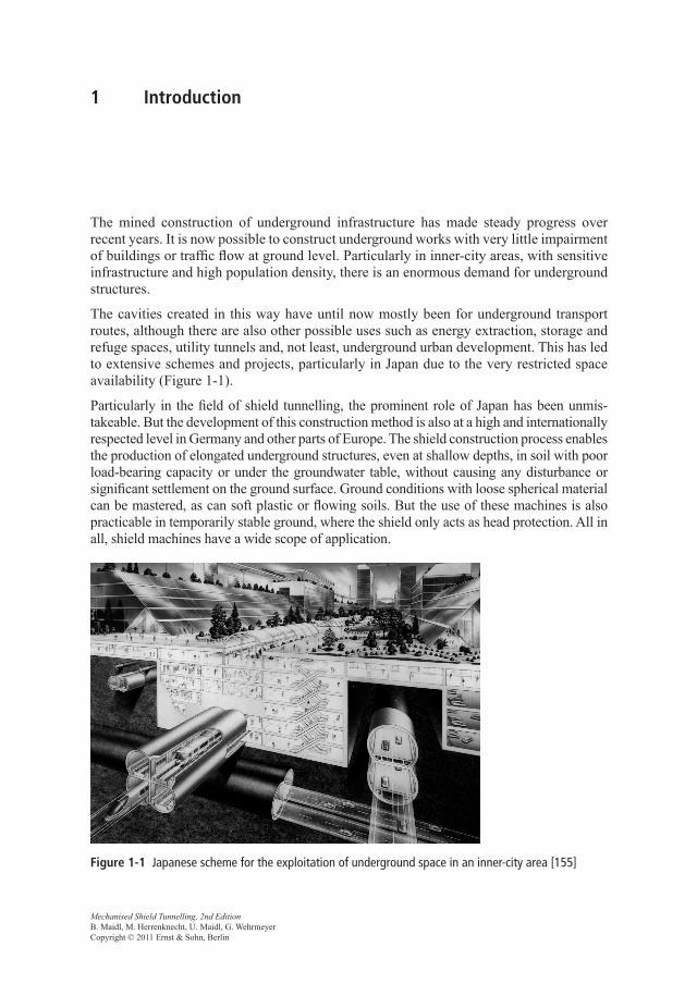
The cavities created in this way have until now mostly been for underground transport routes, although there are also other possible uses such as energy extraction, storage and refuge spaces, utility tunnels and, not least, underground urban development. This has led to extensive schemes and projects, particularly in Japan due to the very restricted space availability (Figure 1-1).
Particularly in the field of shield tunnelling, the prominent role of Japan has been un mis-takeable. But the development of this construction method is also at a high and internationally respected level in Germany and other parts of Europe. The shield construction process enables the production of elongated underground structures, even at shallow depths, in soil with poor load-bearing capacity or under the groundwater table, without causing any disturbance or significant settlement on the ground surface. Ground conditions with loose spherical material can be mastered, as can soft plastic or flowing soils. But the use of these machines is also practicable in temporarily stable ground, where the shield only acts as head protection. All in all, shield machines have a wide scope of application.
Figure 1-1 Japanese scheme for the exploitation of underground space in an inner-city area [155]
2 1 Introduction
The shield construction process could but should not generally replace other methods of tunnelling. It can, however, offer a technically feasible and also economic alternative to other methods of tunnelling in unfavourable geological conditions, for long contract sections, high advance rate requirement or where stringent surface settlement limits apply. The essential advantages and disadvantages are summarised below.
Advantages:
– the possibility of mechanisation and high advance rate, – precision of profile, – minimisation of the effect on buildings on the surface, – improved safety for the miners, – environmentally friendly construction method, – raising of the groundwater table, – little noise, – enables a high-quality and economic lining.
Disadvantages:
– long lead time for the design, production and assembly of the shield machine, – long familiarisation time, – elaborate and expensive site facilities (a separating plant may be required); tenders may
only be competitive for longer tunnels, – performance risk in changeable ground, – the cross-section normally has to be round with little possibility of variation, – high cost of altering the excavated geometry, e.g. for wider sections, – the lining normally has to be specially designed to resist the thrust forces.
Application is therefore practicable where the advantages can be sensibly exploited and the disadvantages are taken into account as far as possible in the design and construction planning. Experience shows that a shield in the smaller diameter range can generally compete with other tunnelling methods for tunnel drives up to 2,000 m. For longer tunnels, economic applications of shield machines are possible and even cheaper than using open machines or conventional methods.
The successful use of a shield always requires meticulous design and planning of the machine, the lining and the logistics. Experience and know-how are essential for a practi-cable and economic scheme. According to [235], too many clients have chosen the wrong machine or construction concept for the ground conditions and have later been faced with unacceptable settlement on the surface, unexpectedly slow advance rates, spalling or fail-ure of the lining, water ingress or other defects. For the client, only a tunnel constructed on schedule, of good quality and at reasonable cost, and with as little impact on the envi-ronment as possible is of interest. The designers of shield equipment need to take these natural concerns into consideration. Mechanical engineering issues have to be effectively linked to those of the tunnel itself. Constant exchange of experience between mechanical and civil engineers is essential, with the appropriate evaluation of experience from com-pleted projects.
1.1 Basic principles and terms 3
1.1 Basic principles and terms
The basic principle of a shield is that a generally cylindrical steel construction is driven along the tunnel axis while the ground is excavated. The steel construction supports the excavated cavity until temporary support or the final lining has been installed. The shield therefore has to resist the pressure of the surrounding ground and hold back any groundwater.
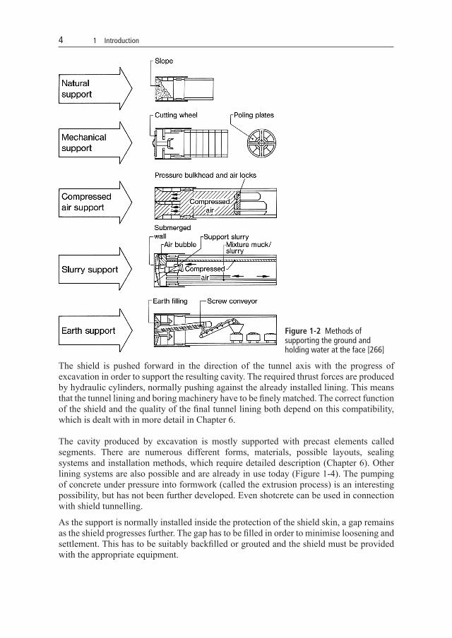
While the cavity along the sides of the tunnel is supported by the shield skin itself, additional support measures will be required to support the face, depending on the ground and groundwater conditions encountered. Figure 1-2 shows five different methods of stabilising the face, which are described in detail in Chapter 2. These are:
– natural support, – mechanical support, – compressed air support, – slurry support, – earth pressure balance support.
These methods of supporting the face represent the great advantage of the shield tunnelling process. In contrast to other methods of tunnelling, it is possible to provide immediate support of the ground as soon as it is disturbed.
In addition to the type of face support, the method of excavation is an important characteristic of shields. The most simple process is manual digging in hand shields, and this is still used today in exceptional cases, for example for short sections and under certain geological conditions. Mechanical excavation is, however, more usual. This can be differentiated into mechanical partial- and full-face excavation. In partial-face excavation, the face is worked in sections using machinery such as hydraulic excavators or roadheaders, which are operated and controlled either by operators or automatically. The full face can be excavated, according to the ground conditions encountered, by open-mode wheels, rim wheels (in some cases with shutters) or closed cutter heads. Further methods are hydraulic excavation using pressurised jets of fluid and extrusion excavation, where the action of the thrust cylinders on highly plastic soil forces it through closable openings in the front wall of the shield. Excavation processes are described in more detail in Chapter 4.
The removal of the excavated material requires special transport systems to move the muck from the face, through the shield and to the surface. The most suitable system depends directly on the nature of the ground encountered and the associated type of face support and excavation, since these factors have a great influence on the consistency and transport properties of the muck. Figure 1-3 gives an initial overview of the possible transport systems through the shield, which will be explained in more detail in Chapter 5. There are numerous transport methods available today, which can be categorised into the three basic groups
– dry transport, – fluid/slurry transport, – high-density solid pumping.
Transport along the tunnel can use pumped pipes, conveyor belts, dumpers or rail-based systems (muck trains). The transfer area to the tunnel transport system is integrated into the backup.
4 1 Introduction
The shield is pushed forward in the direction of the tunnel axis with the progress of excavation in order to support the resulting cavity. The required thrust forces are produced by hydraulic cylinders, normally pushing against the already installed lining. This means that the tunnel lining and boring machinery have to be finely matched. The correct function of the shield and the quality of the final tunnel lining both depend on this compatibility, which is dealt with in more detail in Chapter 6.
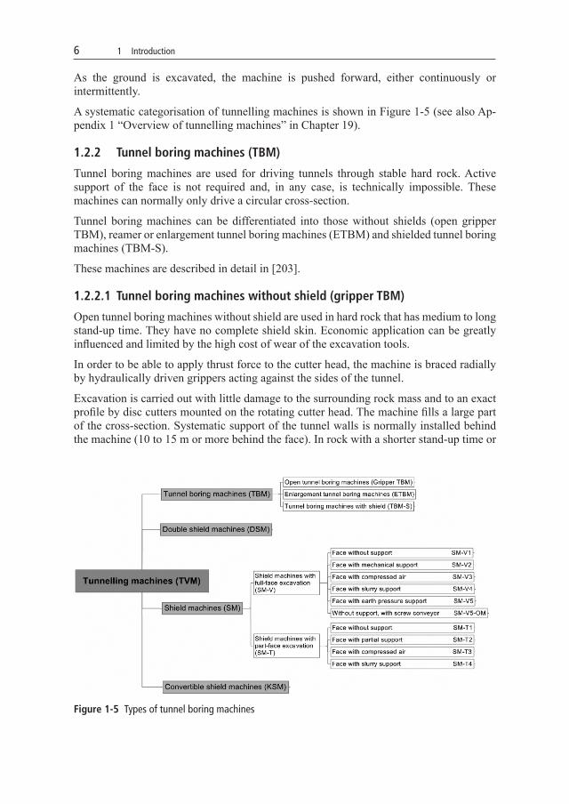
The cavity produced by excavation is mostly supported with precast elements called segments. There are numerous different forms, materials, possible layouts, sealing systems and installation methods, which require detailed description (Chapter 6). Other lining systems are also possible and are already in use today (Figure 1-4). The pumping of concrete under pressure into formwork (called the extrusion process) is an interesting possibility, but has not been further developed. Even shotcrete can be used in connection with shield tunnelling.
As the support is normally installed inside the protection of the shield skin, a gap remains as the shield progresses further. The gap has to be filled in order to minimise loosening and settlement. This has to be suitably backfilled or grouted and the shield must be provided with the appropriate equipment.
Figure 1-2 Methods of supporting the ground and holding water at the face [266]
1.2 Types of tunnel boring machine according to DAUB 5
1.2 Types of tunnel boring machine according to DAUB
The recommendations of DAUB (the German Tunnelling Committee) are reproduced in their entirety in Chapter 19 [54].
1.2.1 Categories of tunnelling machines German association for underground construction (TVM)
Tunnelling machines either excavate the full face with a cutter head or cutting wheel or part of the face with suitable excavation equipment.
These can be tunnel boring machines (TBM), double shield machines (DSM), shield machines (SM) or combination machines (KSM). While the acronym “TBM” in English will be used for all types of tunnelling machines, the German DAUB reserves the abbreviation for the hard rock machines.
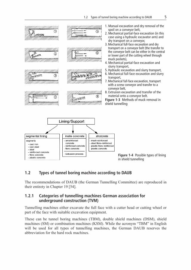
1. Manual excavation and dry removal of the spoil on a conveyor belt,
2. Mechanical partial-face excavation (in this case using a hydraulic excavator arm) and dry transport on a conveyor,
3. Mechanical full-face excavation and dry transport on a conveyor belt (the transfer to the conveyor belt can be either in the central or lower part of the cutting wheel through muck pockets),
4. Mechanical partial-face excavation and slurry transport,
5. Hydraulic excavation and slurry transport,6. Mechanical full-face excavation and slurry
transport,7. Mechanical full-face excavation, transport
with a screw conveyor and transfer to a conveyor belt,
8. Extrusion excavation and transfer of the material onto a conveyor belt.
Figure 1-3 Methods of muck removal in shield tunnelling
Figure 1-4 Possible types of lining in shield tunnelling
6 1 Introduction
As the ground is excavated, the machine is pushed forward, either continuously or intermittently.
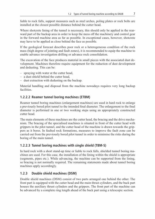
A systematic categorisation of tunnelling machines is shown in Figure 1-5 (see also Ap-pendix 1 “Overview of tunnelling machines” in Chapter 19).
1.2.2 Tunnel boring machines (TBM)
Tunnel boring machines are used for driving tunnels through stable hard rock. Active support of the face is not required and, in any case, is technically impossible. These machines can normally only drive a circular cross-section.
Tunnel boring machines can be differentiated into those without shields (open gripper TBM), reamer or enlargement tunnel boring machines (ETBM) and shielded tunnel boring machines (TBM-S).
These machines are described in detail in [203].
1.2.2.1 Tunnel boring machines without shield (gripper TBM)
Open tunnel boring machines without shield are used in hard rock that has medium to long stand-up time. They have no complete shield skin. Economic application can be greatly influenced and limited by the high cost of wear of the excavation tools.
In order to be able to apply thrust force to the cutter head, the machine is braced radially by hydraulically driven grippers acting against the sides of the tunnel.
Excavation is carried out with little damage to the surrounding rock mass and to an exact profile by disc cutters mounted on the rotating cutter head. The machine fills a large part of the cross-section. Systematic support of the tunnel walls is normally installed behind the machine (10 to 15 m or more behind the face). In rock with a shorter stand-up time or
Figure 1-5 Types of tunnel boring machines
1.2 Types of tunnel boring machine according to DAUB 7
liable to rock falls, support measures such as steel arches, poling plates or rock bolts are installed at the closest possible distance behind the cutter head.
Where shotcrete lining of the tunnel is necessary, this should only be applied in the rear-ward part of the backup area in order to keep the mess off the machinery and control gear in the forward machine area as far as possible. In exceptional cases, however, shotcrete may have to be applied as close behind the face as possible.
If the geological forecast describes poor rock or a heterogeneous condition of the rock mass (high degree of jointing and fault zones), it is recommended to equip the machine to enable advance investigation drilling or advance rock consolidation.
The excavation of the face produces material in small pieces with the associated dust de-velopment. Machines therefore require equipment for the reduction of dust development and dedusting. This can be:
– spraying with water at the cutter head, – a dust shield behind the cutter head, – dust extraction with dedusting on the backup.
Material handling and disposal from the machine nowadays requires very long backup facilities.
1.2.2.2 Reamer tunnel boring machines (ETBM)
Reamer tunnel boring machines (enlargement machines) are used in hard rock to enlarge a previously bored pilot tunnel to the intended final diameter. The enlargement to the final diameter is performed in one or two working steps using an appropriately constructed cutter head.
The main elements of these machines are the cutter head, the bracing and the drive mecha-nism. The bracing of the specialised machines is situated in front of the cutter head with grippers in the pilot tunnel, and the cutter head of the machine is drawn towards the grip-pers as it bores. In faulted rock formations, measures to improve the fault zone can be carried out from the previously bored pilot tunnel in order to minimise the risks during the boring of the main tunnel.
1.2.2.3 Tunnel boring machines with single shield (TBM-S)
In hard rock with a short stand-up time or liable to rock falls, shielded tunnel boring ma-chines are used. For this case, the installation of the lining within the shield is appropriate (segments, pipes etc.). While advancing, the machine can be supported from the lining, so bracing is not normally required. The remaining statements made about tunnel boring machines apply accordingly.
1.2.3 Double shield machines (DSM)
Double shield machines (DSM) consist of two parts arranged one behind the other. The front part is equipped with the cutter head and the main thrust cylinders, and the back part houses the auxiliary thrust cylinders and the grippers. The front part of the machine can be advanced by a complete ring length ahead of the back part using a telescopic section.
8 1 Introduction
In stable hard rock, the gripper shoes resist the drive torque and the thrust forces. The secure fixing of the back part of the machine using the grippers enables the assembly of the segmental lining in the shield tail while boring is in progress. In a stable rock mass, it may also be possible to omit the installation of the lining.
In unstable ground, where the gripper shoes cannot find sufficient resistance, the thrust can be resisted from the last segment ring. The front and back parts of the machine are retracted together and the thrust forces are pushed from the segment ring by the auxiliary thrust cylinders.
It is not normally possible to actively support the face or the sides of the excavation.
Due to the rapid advance of the back part of the machine after a boring stroke has been completed and the grippers are being regripped, the rock mass has to be able to stand up independently until the annular gap has been completely filled with grout or stowed with pea gravel.
1.2.4 Shield machines (SM)
These can be shield machines with full-face excavation (with a cutter head: SM-V) and shield machines with partial-face excavation (using a roadheader boom, excavator: SM-T). Shield machines are used in loose ground above and below the groundwater table. This normally means that the ground around the cavity and at the face has to be supported. Shield machines can be further divided according to the type of face support (Figure 1-5).
1.2.4.1 Shield machines with full-face excavation (SM-V)
1) Face without support (SM-V1)
If the face will stand up, e.g. in clay soil with stiff consistency and sufficient cohesion or in solid rock, open shields can be used. The cutting wheel fitted with tools excavates the soil and the muck is removed on a conveyor belt.
In solid rock liable to rock falls, shield machines with a mostly closed cutter head fitted with disc cutters and fully protected from the unstable ground by a shield skin are nor-mally used. The thrust forces and the cutter head drive torque are transferred through the thrust cylinders to the last ring of segments installed.
2) Face with mechanical support (SM-V2)
With tunnelling machines with mechanical support, the support of the face during excava-tion is provided by elastically fixed support plates arranged in the openings of the cutting wheel. In practice, however, experience shows that that no appreciable mechanical sup-port of the face can be provided by the rotating cutting wheel. For this reason, this type of cutting wheel did not prove successful in unstable ground and is no longer in use today. The mechanical face support by the cutting wheel or the support plates should only be considered a supplementary safety measure and the supporting effect should not be taken into account in calculations to verify the stability of the face.