Embed Size (px)
Citation preview
Naval Aerospace Medical Research Laboratory
NAMRL Technical Memorandum 96-1
BACKGROUND AND INSTRUMENTATION FOR THE HELICOPTER INSTRUMENT SCAN PATTERN RESEARCH CONDUCTED AT NAS WHITING FIELD
L. A. Temme and D. L. Still
19971104 080 Naval Aerospace Medical Research Laboratory
51 Hovey Road Pensacola, Florida 32508-1046
Approved for public release; distribution unlimited.

Reviewed and approved^ Li^-u
vutzk_^ j. C./PATEE; CAPT, MSC USN
/ Coöunanding Officer
This research was sponsored by the Naval Medical Research and Development Command under work request
63707N M0096.001-7208.
The views expressed in this article are those of the authors and do not reflect the official policy or position of the Department of the Navy, Department of Defense, nor the U.S. Government.
Volunteer subjects were recruited, evaluated, and employed in accordance with the procedures specified in the Department of Defense Directive 3216.2 and Secretary of the Navy Instruction 3900.39 series. These instructions are based upon voluntary informed consent and meet or exceed the provisions of prevailing national
and international guidelines.
Trade names of materials and/or products of commercial or nongovernment organizations are cited as needed for precision. These citations do not constitute official endorsement or approval of the use of such commercial
materials and/or products.
Reproduction in whole or in part is permitted for any purpose of the United States Government.
NAVAL AEROSPACE MEDICAL RESEARCH LABORATORY 51 HOVEY ROAD, PENSACOLA, FL 32508-1046
NAMRL Technical Memorandum 96-1
BACKGROUND AND INSTRUMENTATION FOR THE HELICOPTER INSTRUMENT SCAN PATTERN RESEARCH CONDUCTED AT NAS
WHITING FIELD
L. A. Temme and D. L. Still
fS
Approved for public release; distribution unlimited.
ABSTRACT
Effectively scanning and interpreting flight instruments are crucially important skills for pilots. Despite the facts that much of pilot training is devoted to developing an effective scan and that virtually all successful pilots have effective scans, there is surprisingly little objective information about instrument scan patterns. Most studies of scan patterns have used either pilots' self reports of their scanning or measurements made with relatively invasive eye tracking procedures, procedures so invasive as to have likely affected the behavior they were intended to measure in the first place. Furthermore, almost all of these studies have been executed under laboratory conditions that were at best poor or low fidelity emulations of the aviation task. In order to fill these voids in the literature and to provide objective, fleet-relevant information describing instrument scan patterns under realistic situations, the Naval Aerospace Medical Research Laboratory developed the capability of monitoring, in an essentially noninvasive fashion, the scanning behaviors of pilots as they fly the full-sized, motion-based, high fidelity, helicopter instrument training simulator at the Naval Air Station Whiting Field. The present paper provides a photographic description of this research installation.
Acknowledgments
The success of this project has been critically dependent upon the coordinated talents and skills of many different people, each generously extending themselves beyond their prescribed duties for the success of this project. Unfortunately, there are just far too many people to acknowledge each individually and if I were to attempt such an acknowledgment, I will unavoidably embarrass myself by forgetting someone whose contribution was crucial; so I will not even try. But in general, this work would not have occurred without the cooperation, support and interest of the Commanding Officer of Training Wing and staff, including the Squadron Commanding Officers, Executive Officers, Training Officers, Project Officers, instructor and student pilot volunteers, Ensigns, the many contractual personnel, the generous fine individuals associated with NAWC/TSD, NAMRL professional, technical and support staff, and as always, the secretaries without whom, nothing gets done.
INTRODUCTION
In late June of 1990, representatives of the Office of Naval Research (ONR), the Naval Research Laboratory (NRL), and the Naval Medical Research and Development Command (NMRDC) visited the Advanced Helicopter Training Squadron, HT-18, at Naval Air Station (NAS) Whiting Field, on the invitation of the Commanding Officer of HT-18, CDR Michael Price. The purpose of this meeting was to discuss pilot training related to visual scanning techniques during instrument flight. During the meeting, CDR Price and several of his senior instructors discussed concerns regarding training strategies for effective instrument scanning techniques.
The following is a summary of the concerns expressed at that meeting by CDR Price and his instructors (1):
1. Often student pilots do not seem to monitor the prescribed instruments for the maneuver they are flying;
2. Some student pilots often seem to fixate on one or two instruments rather than scan the ensemble of pertinent instruments;
3. There was a strong belief that improved aircrew coordination could contribute significantly to establishing strategies for more efficient scanning patterns and improved piloting performance;
4. There was some uncertainty expressed about being able to describe explicitly what constitutes the best scanning techniques for certain critical maneuvers;
5. There were expressions of an intuitive feeling that highly skilled pilots exhibit good scanning behaviors and that poor pilots exhibit poor scanning behaviors; and
6. They expressed the need for improved methods and training devices for teaching good scanning behavior particularly in a flight simulator.
As a consequence of the meeting, ONR requested that the National Academy of Science's National Research Council (NRC) Committee of Vision discuss this issue during the Committee's July 1990 meeting (2). The NRC Committee of Vision responded in October 1990; the Committee of Vision was not aware of evidence to indicate a relationship between scan patterns and performance. The Committee of Vision reported that scan measurements are a useful source of information for laying out flight instruments, and for establishing simulator field of view requirements, to show discriminability of symbology, camouflage, to provide training feedback on instrument monitoring. The Committee of Vision expressed the opinion that the problems noted in the site visit may be amenable to research (3).
In November 1990, a Broad Agency Announcement (BAA) was published requesting research on the visual scan of helicopter pilot trainees to identify how best to train proper ocular motility for each type of helicopter maneuver. Twenty research proposals received in response to the BAA were reviewed by a selection committee of ONR, NMRDC, and NRL representatives. None of the proposals met all the criteria of the selection committee, so none were funded and the research not undertaken at that time (3).
Independent of the above effort and the interest expressed by the training community, the Naval Aerospace Medical Research Laboratory (NAMRL) collaborated with Dr. Kent Daum, Professor of Optometry at the University of Alabama, Birmingham, to compare the visual tracking behavior of pilots with that of expert athletes. This study, conducted during 1991 at Whiting Field with volunteer pilots from Training Air Wing Five, maintained a research presence and dialogue between the training and the medical research communities and was possibly instrumental, at least to some extent, in keeping alive interest in scan pattern research (4).
In 1992, the Commanding Officer of HT-18 formally requested the Director of Navy Test and Evaluation and Technology Requirements to assist in getting pilot visual scan techniques research included in the Science and
1

Technology planning guidance, a request that was endorsed by the Commander, Training Air Wing FIVE and the Chief of Naval Air Training (5). In 1992, the NAMRL proposal Acquisition of Instrument Scan Patterns by Navy/Marine Student Helicopter Pilots was funded by NMRDC. The goal of the research was to provide helicopter instructor pilots with an integrated set of teaching aids to facilitate the acquisition of instrument scan patterns by student helicopter pilots training in the helicopter simulator (6).
The proposed set of integrated teaching aids included:
1. An on-line instructor workstation envisioned as a display installed in the instructor's workstation in the simulator. The display was to provide the instructor with an unambiguous, real-time display of the student's instrument scan
pattern. This was to be achieved with a video display of the instrument panel with a superimposed cursor indicating the student's line of sight.
2. An off-line playback workstation for post-flight review and debriefing envisioned as a replay capability for reviewing the entire flight and displaying the scan pattern, instrument displays, and the control responses.
3. A library of illustrative scan patterns envisioned as a set of instrument scans that instructors could use to demonstrate scan techniques in a lecture-type setting. The library of scans was viewed as a resource to aid in the standardization of the training of instructors and their criteria.
4. An unambiguous, objective measure of the instrument scan with which to evaluate the appropriateness and effectiveness of a student's scan. This was seen as particularly useful for situations in which a students' flight performance might suggest a problem with instrument scan.
5. Characterization and description of changes in instrument scan patterns for different maneuvers and functions of skill acquisition.
6. Performance-based biomedical standards for personnel selection and retention based upon characteristics of instrument scanning capabilities.
7. An instrument scan part-task trainer to provide training in specific, defined aspects of instrument scan.
8. The development of scenarios for training specific aspects of instrument scanning. We thought that the data would demonstrate particularly difficult maneuvers or scanning tasks that would then be targeted for training. Specifically, situations could be identified that provoke the breakdown of instrument scan and in these situations train the re-acquisition of scan.
The above list of products was a point of departure; the design of the projected products have evolved and been refined as the research has progressed. The Commander, Training Air Wing FIVE and staff have been briefed regularly on this research design, goals, and progress (7-9). During the year that NMRDC initiated support for this project, Dr. Paul Kerr joined this research team as an American Society of Engineering Education (ASEE) postdoctoral fellow, under a program funded by Office of Naval Technology (ONT) (10). The first of 3 years of ONR support for this project began in 1993.
MATERIALS AND METHODS
At Whiting Field, students follow a prescribed training syllabus through 15 helicopter simulator events, about 1 h each. In order to assemble a meaningful database, we had to develop the capability of recording instrument scan
patterns in a way that will minimally impact flight training. To accomplish this, we installed an eye tracker (manufactured by ISCAN, Inc.) in one of the motion-based helicopter instrument training simulators. The eye tracker used a remote infrared sensing system measured eye pointing and eye position in an almost totally noninvasive fashion. The approach did not require anything to be attached to the head. The eye tracker recorded two
landmarks of the eye illuminated with an infrared light. An infrared light was used because it is not visible to the human. The video camera of the eye tracker recorded the image of the pupil and the corneal reflection of the infrared light. Software implementations of image analysis algorithms calculated the center of the pupil and the corneal reflection. A calibration procedure was necessary before data collection began for each test subject. During the calibration, the subject looked at nine predetermined locations on the instrument panel, and the relative positions of the pupil image and corneal reflection were recorded. In this way, the instrument panel was mapped into nine regions and the intervening points determined by interpolation. The calibration took approximately 2-3 min to complete and was done before each data collection session began.
This stage of the research is purely observational; we are recording what the helicopter students do under normal circumstances in their routine training environment. This is not an experiment in the true sense of the word. We are not manipulating any parameters (independent variables) or measuring the effects on any dependent variable. We are not perturbing the system in any way other than by inserting the initial period of calibration and an unavoidable awareness by the student pilot that the measurements are being made. After the simulator event, when asked, student pilots invariably report that after a few minutes of flying they are completely engrossed in their task and are oblivious to the eye tracker and the measurements. In order to carry this work forward into a truly experimental approach that includes hypothesis testing (hypotheses generated from the observations made at Whiting), we are developing an in- house, laboratory eye-tracking capability with commercially available research quality, desktop, computer-based flight simulators.
DESCRIPTION OF WHITING FIELD INSTALLATION
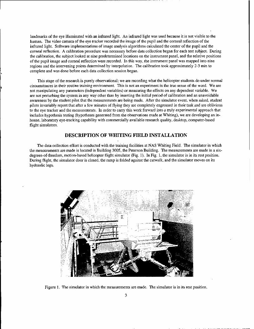
The data collection effort is conducted with the training facilities at NAS Whiting Field. The simulator in which the measurements are made is located in Building 3005, the Peterson Building. The measurements are made in a six- degrees-of-freedom, motion-based helicopter flight simulator (Fig. 1). In Fig. 1, the simulator is in its rest position. During flight, the simulator door is closed, the ramp is folded against the catwalk, and the simulator moves on its hydraulic legs.
Figure 1. The simulator in which the measurements are made. The simulator is in its rest position.
3
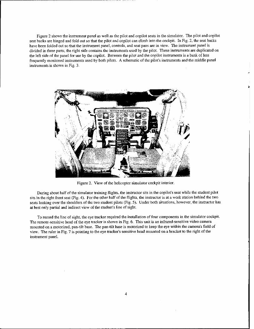
Figure 2 shows the instrument panel as well as the pilot and copilot seats in the simulator. The pilot and copilot seat backs are hinged and fold out so that the pilot and copilot can climb into the cockpit. In Fig. 2, the seat backs have been folded out so that the instrument panel, controls, and seat pans are in view. The instrument panel is divided in three parts; the right side contains the instruments used by the pilot. These instruments are duplicated on the left side of the panel for use by the copilot. Between the pilot and the copilot instruments is a bank of less frequently monitored instruments used by both pilots. A schematic of the pilot's instruments and the middle panel instruments is shown in Fig. 3.
Figure 2. View of the helicopter simulator cockpit interior.
During about half of the simulator training flights, the instructor sits in the copilot's seat while the student pilot sits in the right front seat (Fig. 4). For the other half of the flights, the instructor is at a work station behind the two seats looking over the shoulders of the two student pilots (Fig. 5). Under both situations, however, the instructor has at best only partial and indirect view of the student's line of sight.
To record the line of sight, the eye tracker required the installation of four components in the simulator cockpit. The remote-sensitive head of the eye tracker is shown in Fig. 6. This unit is an infrared-sensitive video camera mounted on a motorized, pan-tilt base. The pan-tilt base is motorized to keep the eye within the camera's field of view. The ruler in Fig. 7 is pointing to the eye tracker's sensitive head mounted on a bracket to the right of the instrument panel.
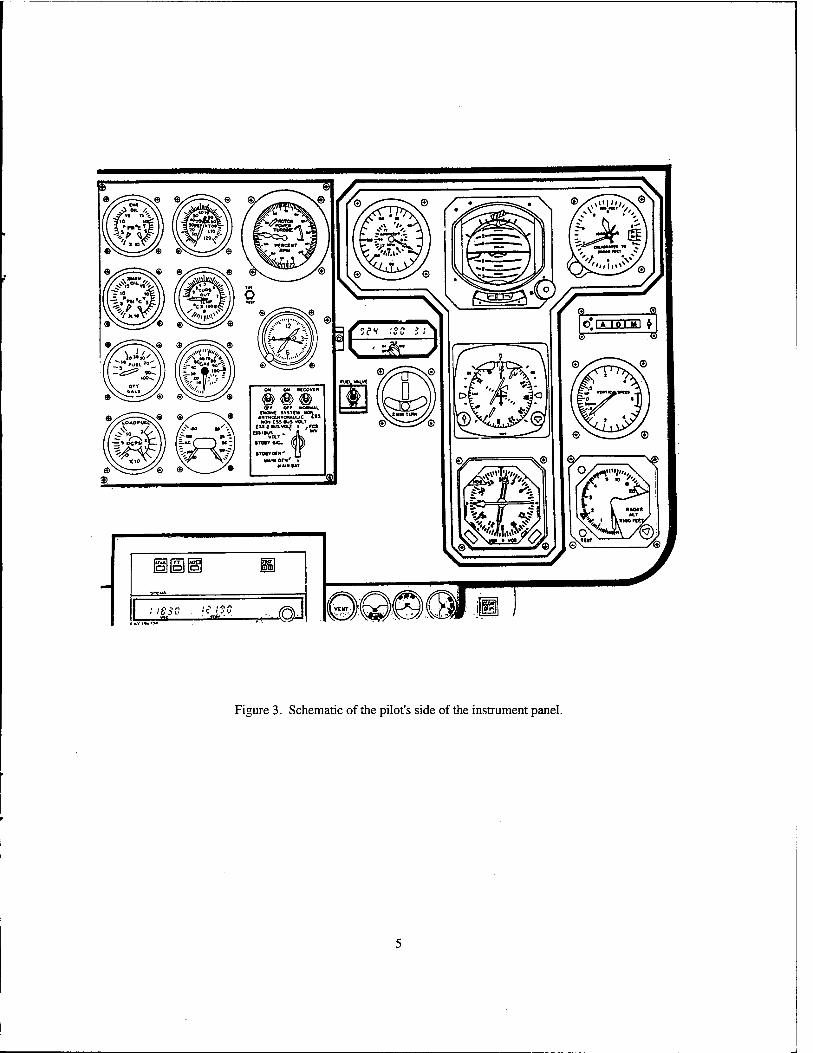
Figure 3. Schematic of the pilot's side of the instrument panel.
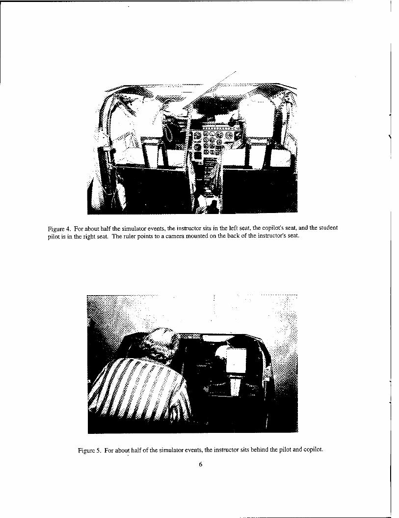
Figure 4. For about half the simulator events, the instructor sits in the left seat, the copilot's seat, and the student pilot is in the right seat. The ruler points to a camera mounted on the back of the instructor's seat.
Figure 5. For about half of the simulator events, the instructor sits behind the pilot and copilot.
6
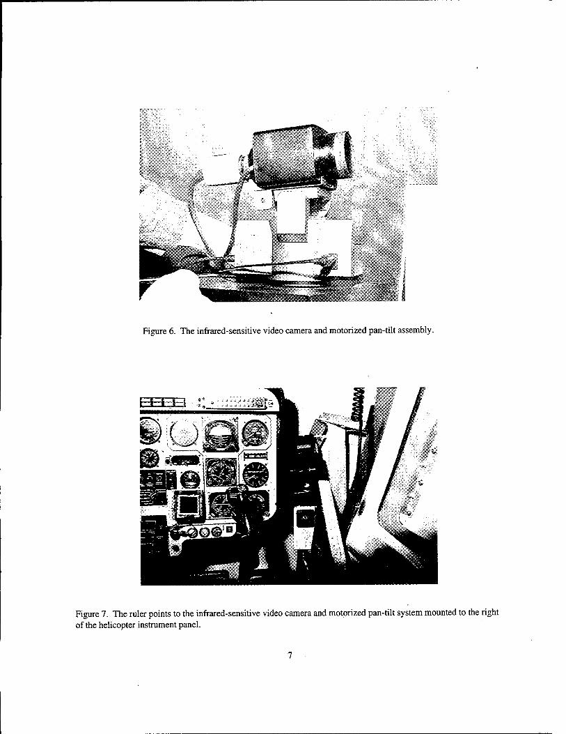
Figure 6. The infrared-sensitive video camera and motorized pan-tilt assembly.
Figure 7. The ruler points to the infrared-sensitive video camera and motorized pan-tilt system mounted to the right of the helicopter instrument panel.
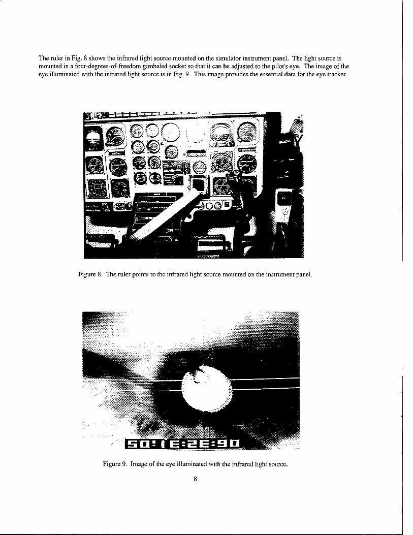
The ruler in Fig. 8 shows the infrared light source mounted on the simulator instrument panel. The light source is mounted in a four-degrees-of-freedom gimbaled socket so that it can be adjusted to the pilot's eye. The image of the eye illuminated with the infrared light source is in Fig. 9. This image provides the essential data for the eye tracker.
Figure 8. The ruler points to the infrared light source mounted on the instrument panel.
Figure 9. Image of the eye illuminated with the infrared light source.
The photograph appears blurred because it was taken from a CRT playing the video tape, and the photo captured two video frames from the CRT. The photo shows two sets of crosshairs; one set marks the center of the reflection of the light from the cornea, and the second cross hair shows the center of the pupil. The numbers at the top are time code that provides a synchronous signal with the simulator state data set.
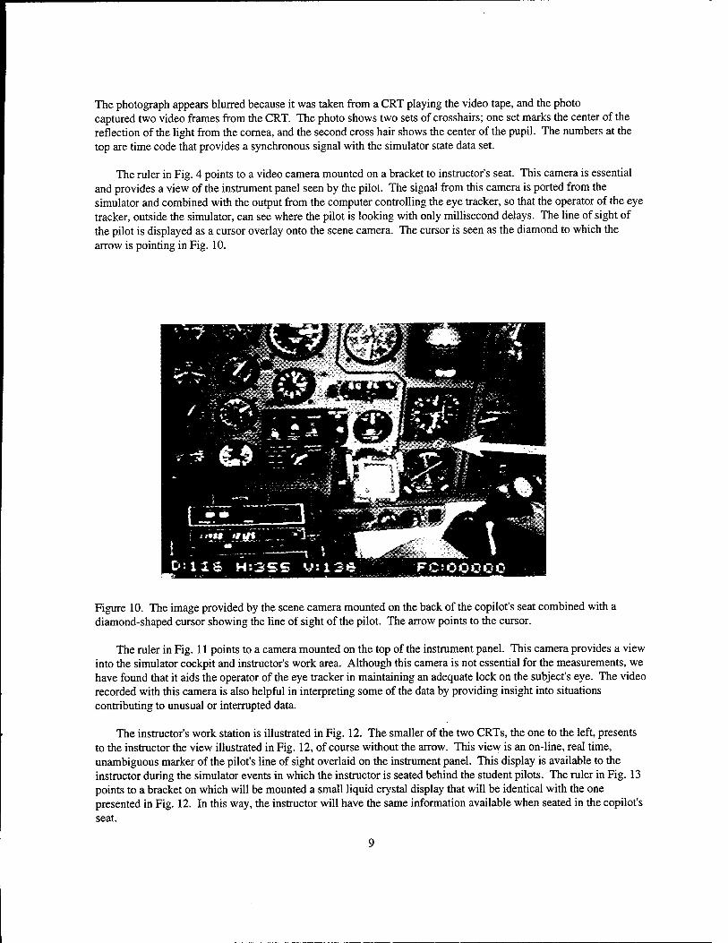
The ruler in Fig. 4 points to a video camera mounted on a bracket to instructor's seat. This camera is essential and provides a view of the instrument panel seen by the pilot. The signal from this camera is ported from the simulator and combined with the output from the computer controlling the eye tracker, so that the operator of the eye tracker, outside the simulator, can see where the pilot is looking with only millisecond delays. The line of sight of the pilot is displayed as a cursor overlay onto the scene camera. The cursor is seen as the diamond to which the arrow is pointing in Fig. 10.
Figure 10. The image provided by the scene camera mounted on the back of the copilot's seat combined with a diamond-shaped cursor showing the line of sight of the pilot. The arrow points to the cursor.
The ruler in Fig. 11 points to a camera mounted on the top of the instrument panel. This camera provides a view into the simulator cockpit and instructor's work area. Although this camera is not essential for the measurements, we have found that it aids the operator of the eye tracker in maintaining an adequate lock on the subject's eye. The video recorded with this camera is also helpful in interpreting some of the data by providing insight into situations contributing to unusual or interrupted data.
The instructor's work station is illustrated in Fig. 12. The smaller of the two CRTs, the one to the left, presents to the instructor the view illustrated in Fig. 12, of course without the arrow. This view is an on-line, real time, unambiguous marker of the pilot's line of sight overlaid on the instrument panel. This display is available to the instructor during the simulator events in which the instructor is seated behind the student pilots. The ruler in Fig. 13 points to a bracket on which will be mounted a small liquid crystal display that will be identical with the one presented in Fig. 12. In this way, the instructor will have the same information available when seated in the copilot's seat.
9
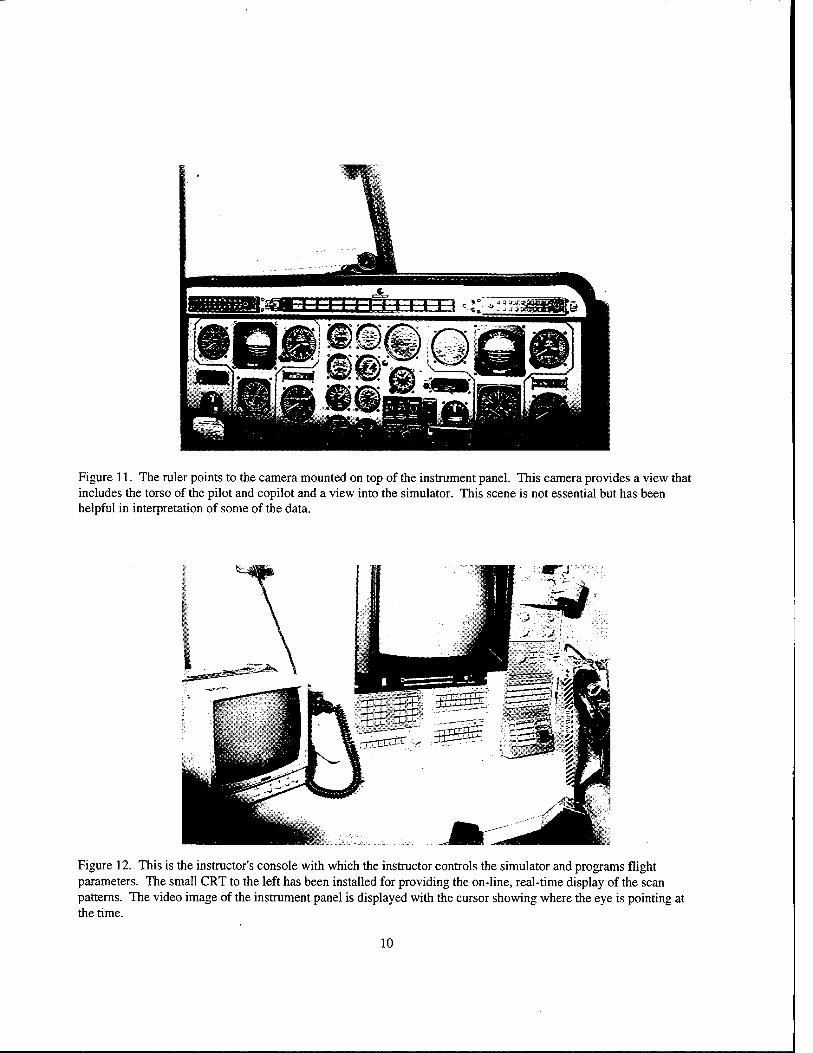
Figure 11. The ruler points to the camera mounted on top of the instrument panel. This camera provides a view that includes the torso of the pilot and copilot and a view into the simulator. This scene is not essential but has been helpful in interpretation of some of the data.
Figure 12. This is the instructor's console with which the instructor controls the simulator and programs flight parameters. The small CRT to the left has been installed for providing the on-line, real-time display of the scan patterns. The video image of the instrument panel is displayed with the cursor showing where the eye is pointing at the time.
10
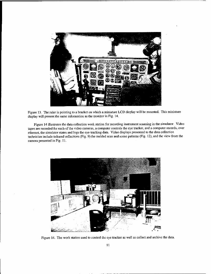
Figure 13. The ruler is pointing to a bracket on which a miniature LCD display will be mounted. This miniature display will present the same information as the monitor in Fig. 14.
Figure 14 illustrates the data collection work station for recording instrument scanning in the simulator. Video tapes are recorded for each of the video cameras, a computer controls the eye tracker, and a computer records, over ethernet, the simulator states and logs the eye-tracking data. Video displays presented to the data collection technician include infrared reflections (Fig. 9) the melded scan and scene patterns (Fig. 12), and the view from the camera presented in Fig. 11.
Figure 14. The work station used to control the eye tracker as well as collect and archive the data.
11
DISCUSSION
The instrumentation described above has been used to collect complete data sets on 45 student helicopter pilots. To our knowledge, this is the first time that eye tracking has successfully been accomplished in such a minimally invasive fashion in an operationally realistic motion-based flight simulator. The data, although only descriptive, i.e. not an experimental manipulation of variables, are longitudinal. The data will describe the change in scanning behavior that occurs over time with the acquisition of pilot expertise. The complete database, consisting of 100 student pilots, will be sufficiently large and robust for statistical analysis as well as an evaluation of individual differences.
The installation described at NAS Whiting Field is for an observational mode of scientific investigation. The research design does not allow for the experimental manipulation of independent variables to evaluate their impact on scanning or flight performance or other hypothesis testing experimental strategies. An additional eye-tracking installation is nearing completion in NAMRL's laboratory facility at NAS Pensacola. This new facility is designed for the experimental manipulation of selected variables within a controlled experimental situation for the testing of hypotheses.
RECOMMENDATION
The facilities at NAS Whiting Field and the one currently being developed at NAS Pensacola provide a unique national resource for the experimental analysis of scan patterns and pilot performance and as such could have a widespread impact on not only the military but also civilian aviation communities. These resources should continue to be developed and used for enhancing the effectiveness and safety of military and civilian aviation (11).
12

REFERENCES
1. Carter, RC and Malecki, GS. Memorandum for the record. Office of the Chief of Naval Research, Department of the Navy, July, 1990.
2. Malecki, GS Letter dated 11 July 1990 from the Cognitive and Neural Sciences Division, Code 1142 to Dr. Milton Whitcomb, Committee on Vision, H-186.
3. Carter, R. Helicopter Training Research: A Search for Worthwhile Proposals. Briefing, Sept 1991.
4. Daum, KM, Temme, LA, Corliss, DA, Wagenknecht, L. Conjugate oculomotor tracking capabilities of helicopter pilots. Protocol for Investigation: Summer 1991, Naval Aerospace Medical Research Laboratory, Naval Air Station, Pensacola, School of Optometry and Public Health, University of Alabama at Birmingham. 1991.
5. Roberts, PE., Commanding Officer, Helicopter Training Squadron EIGHTEEN, Letter 13000 Ser 00000/123 of 14 May 1992 to Director of Navy Test and Evaluation and Technology Requirements (OP-091).
6. Temme, LA. Acquisition of instrument scan patterns by Navy/Marine student helicopter pilots. In: 1992 Command History, Naval Aerospace Medical Research Laboratory, Pensacola, FL, 1993, pp. 62-63.
7. Mateczun, AJ. Letter 3900 0971 Ser 02A of 15 Nov 1993 from the Commanding Officer, Naval Aerospace Medical Research Laboratory to Commander, Training Air Wing FIVE.
8. Abshier, RO. Letter 3900 Ser 71400/0239 of 01 Mar, 1994 from the Commander, Training Air Wing FIVE to Dr. Steven Zornetzer, Office of Naval Research.
9. Abshier, RO. Letter 3900 Ser 71400/0216 of 01 Mar 1994 from the Commander, Training Air Wing FIVE to Commanding Officer, Naval Medical Research and Development Command.
10. Kerr, P W. Non-invasive Monitoring of Helicopter Pilots' Instrument Scan Patterns in a Motion-Based Simulator. Postdoctoral Fellowship Application to the American Society for Engineering Education for the
Office of Naval Technology, 1992.
11. Nakagawara, VB. Vision Research Team Coordinator Letter of May 1995 to LA Temme, Naval Aerospace Medical Research Laboratory, concerning Prototype Aircraft Instrument Scanning System.
13
REPORT DOCUMENTATION PAGE Form Approved
OMB No. 0704-0188
Public reporting burden for this collection of information is estimated to average 1 hour per response, including the time for reviewing instructions, searching existing data sources, | gathering and maintaining the data needed, and completing and reviewing the collection of information. Send comments regarding this burden estimate or any other aspect of this e collection of information, including suggestions for reducing this burden, to Washington Headquarters Services, Directorate for Information Operations and Reports, 1215 Jefferson £ Davis Highway, Suite 1204. Arlington, VA 22202-4302, and to the Office of Management and Budget. Paperwork Reduction Project (0704-0188). Washington, DC 20503. c
1. AGENCY USE ONLY (Leave blank) 2. REPORT DATE
14 June 1996 3. REPORT TYPE AND DATES COVERED
4. TITLE AND SUBTSTLE Background and Instrumentation for the Helicopter Instrument Scan Pattern Research Conducted at NAS Whiting Field
6. AUTHOR(S) Leonard A. Temme and David L. Still
5. FUNDING NUMBERS
63707N M0096.001-7208
7. PERFORMING ORGANIZATION NAME(S) AND ADDRESS(ES) NAVAL AEROSPACE MEDICAL RESEARCH LABORATORY 51HOVEYROAD PENSACOLA FL 32508-1046
l 8. PERFORMING ORGANIZATION > REPORT NUMBER
I NAMRL Technical Memorandum 96-1
9. SPONSORING /MONITORING AGENCY NAME(S) AND ADDRESS(ES) Naval Medical Research and Development Command National Naval Medical Center Building 1, Tower 12 8901 Wisconsin Avenue Bethesda, MD 20889-5606
10. SPONSORING /MONITORING AGENCY REPORT NUMBER
11. SUPPLEMENTARY NOTES
12a. DISTRIBUTION/AVAILABILITY STATEMENT
Approved for public release; distribution unlimited.
| 12b. DISTRIBUTION CODE i <
13. ABSTRACT (Maximum 200 words)
Effectively scanning and interpreting flight instruments are crucially important skills for pilots. Despite the facts that much of pilot training is devoted to developing an effective scan and that virtually all successful pilots have effective scans, there is surprisingly little objective information about instrument scan patterns. Most studies of scan patterns have used either pilots' self reports of their scanning or measurements made with relatively invasive eye tracking procedures, procedures so invasive as to have likely affected the behavior they were intended to measure in the first place. Furthermore, almost all of these studies have been executed under laboratory conditions that were at best poor or low fidelity emulations of the aviation task. In order to fill these voids in the literature and to provide objective, fleet-relevant information describing instrument scan patterns under realistic situations, NAMRL developed the capability of monitoring, in an essentially non-invasive fashion, the scanning behaviors of pilots as they fly the full-sized, motion-based, high fidelity, helicopter instrument training simulator at NAS Whiting Field. The present paper provides a photographic description of this research installation.
14. SUBJECT TERMS
Instrument scan, Simulator, Instrument flight rules, Eye movements, Aviators, Pilots, Scan patterns
| 15. DUMBER O? PAGES
1 16 l 16. PRICE CODE
17. SECURITY CLASSIFICATION 18. SECURITY CLASSIFICATION OF REPORT I OF THIS PAGE
19. SECURITY CLASSIFICATION | 20. LIMITATION OF ABSTRACT] OF ABSTRACT
UNCLASSIFIED UNCLASSIFIED UNCLASSIFIED SAR NSN 7540-01-280-5500 is Standard Form 298 (Rev. 2-83}
Prescribed by ANSI Std. Z3S-18 ?Qa-7n?