Embed Size (px)
DESCRIPTION
Balloon – EUSO Xenon / UV LED Flasher Calibration. Evgeny Kuznetsov for UAH / MSFC GLS team University of Alabama in Huntsville. Flasher Calibration Technique. GLS flasher contains Xenon Lamp with 355nm optical filter and 365nm UV LED with 1W optical output. - PowerPoint PPT Presentation
Citation preview
October 1 -10, 2014 JEM-EUSO Workshop - Toulouse 1
Balloon – EUSO Xenon / UV LED Flasher
Calibration
Evgeny Kuznetsov for UAH / MSFC GLS team
University of Alabama in Huntsville
October 1 -10, 2014 JEM-EUSO Workshop - Toulouse 2
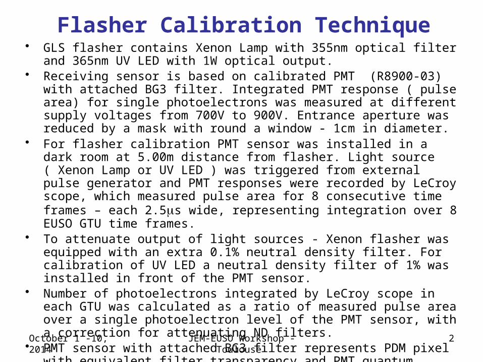
• GLS flasher contains Xenon Lamp with 355nm optical filter and 365nm UV LED with 1W optical output.
• Receiving sensor is based on calibrated PMT (R8900-03) with attached BG3 filter. Integrated PMT response ( pulse area) for single photoelectrons was measured at different supply voltages from 700V to 900V. Entrance aperture was reduced by a mask with round a window - 1cm in diameter.
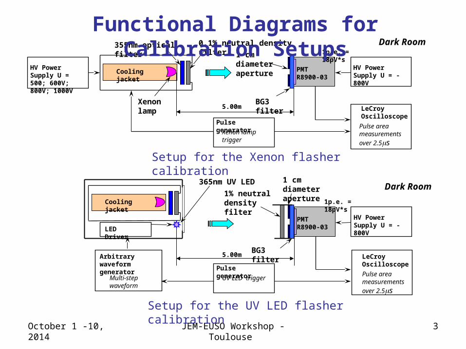
• For flasher calibration PMT sensor was installed in a dark room at 5.00m distance from flasher. Light source ( Xenon Lamp or UV LED ) was triggered from external pulse generator and PMT responses were recorded by LeCroy scope, which measured pulse area for 8 consecutive time frames – each 2.5ms wide, representing integration over 8 EUSO GTU time frames.
• To attenuate output of light sources - Xenon flasher was equipped with an extra 0.1% neutral density filter. For calibration of UV LED a neutral density filter of 1% was installed in front of the PMT sensor.
• Number of photoelectrons integrated by LeCroy scope in each GTU was calculated as a ratio of measured pulse area over a single photoelectron level of the PMT sensor, with a correction for attenuating ND filters.
• PMT sensor with attached BG3 filter represents PDM pixel with equivalent filter transparency and PMT quantum efficiency, that eliminates needs in photon to p.e. conversion. Calibration data is documented in photoelectrons.
Flasher Calibration Technique
October 1 -10, 2014 JEM-EUSO Workshop - Toulouse 3
Cooling jacket
5.00mXenon lamp
355nm optical filter 0.1% neutral density filter
PMT R8900-03
Dark Room
BG3 filter
1 cm diameter aperture HV Power Supply
U = -800VHV Power Supply U = 500; 600V; 800V; 1000V
LeCroy Oscilloscope
Pulse generator
Cooling jacket
5.00m
365nm UV LED
PMT R8900-03
Dark Room1 cm diameter aperture
HV Power Supply U = -800V
LED Driver
LeCroy Oscilloscope
Pulse area measurements
over 2.5ms
Xenon lamp trigger
Pulse generator
UV LED trigger
Arbitrary waveform generator
Multi-step waveform
1% neutral density filter
1p.e. = 18pV*s
1p.e. = 18pV*s
Setup for the Xenon flasher calibration
Setup for the UV LED flasher calibration
Pulse area measurements
over 2.5ms
BG3 filter
Functional Diagrams for Calibration Setups
October 1 -10, 2014 JEM-EUSO Workshop - Toulouse 4
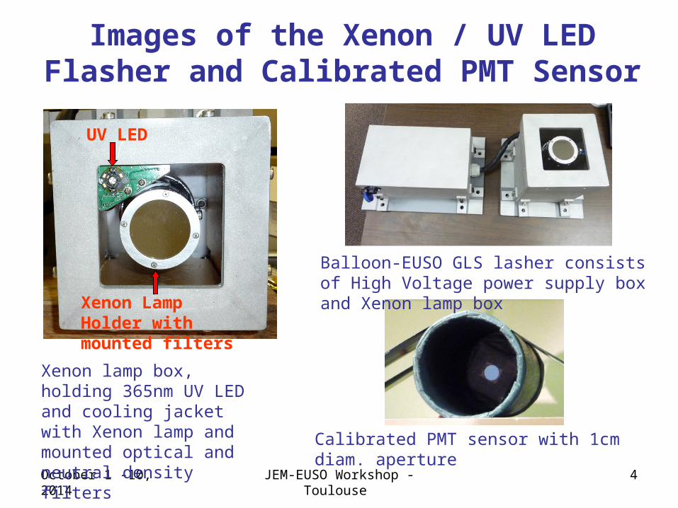
Images of the Xenon / UV LED Flasher and Calibrated PMT Sensor
UV LED
Xenon Lamp Holder with mounted filters
Xenon lamp box, holding 365nm UV LED and cooling jacket with Xenon lamp and mounted optical and neutral density filters
Balloon-EUSO GLS lasher consists of High Voltage power supply box and Xenon lamp box
Calibrated PMT sensor with 1cm diam. aperture
October 1 -10, 2014 JEM-EUSO Workshop - Toulouse 5
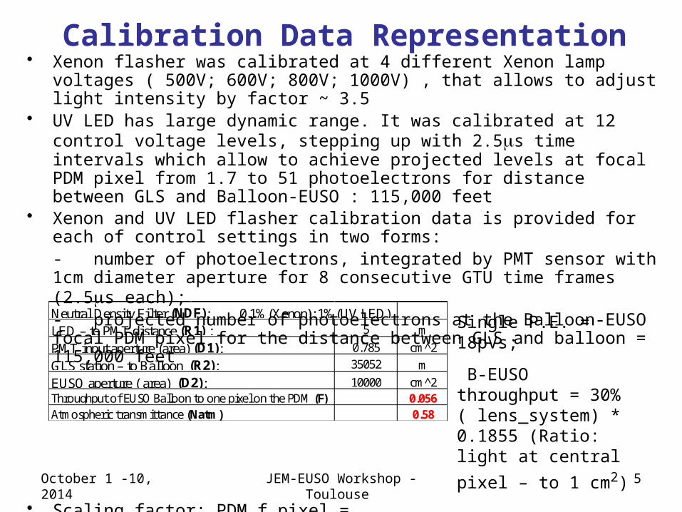
• Xenon flasher was calibrated at 4 different Xenon lamp voltages ( 500V; 600V; 800V; 1000V) , that allows to adjust light intensity by factor ~ 3.5
• UV LED has large dynamic range. It was calibrated at 12 control voltage levels, stepping up with 2.5ms time intervals which allow to achieve projected levels at focal PDM pixel from 1.7 to 51 photoelectrons for distance between GLS and Balloon-EUSO : 115,000 feet
• Xenon and UV LED flasher calibration data is provided for each of control settings in two forms: - number of photoelectrons, integrated by PMT sensor with 1cm diameter aperture for 8 consecutive GTU time frames (2.5ms each);- projected number of photoelectrons at the Balloon-EUSO focal PDM pixel for the distance between GLS and balloon = 115,000 feet
• Scaling factor: PDM_f_pixel = Pulse_area/18pVs*(R1/R2)2*D2/D1*F*Natm/NDF
Calibration Data Representation
Single P.E. = 18pVs;
B-EUSO throughput = 30% ( lens_system) * 0.1855 (Ratio: light at
central pixel – to 1 cm2)
Neutral Density Filter (NDF): 0.1%(Xenon); 1%(UV LED)LED – to PMT distance (R1) : 5 m
PMT input aperture (area) (D1): 0.785 cm^2
GLS station – to Balloon (R2): 35052 m
EUSO aperture ( area) (D2): 10000 cm^2Throughput of EUSO Balloon to one pixel on the PDM (F) 0.056Atmospheric transmittance (Natm) 0.58
October 1 -10, 2014 JEM-EUSO Workshop - Toulouse 6
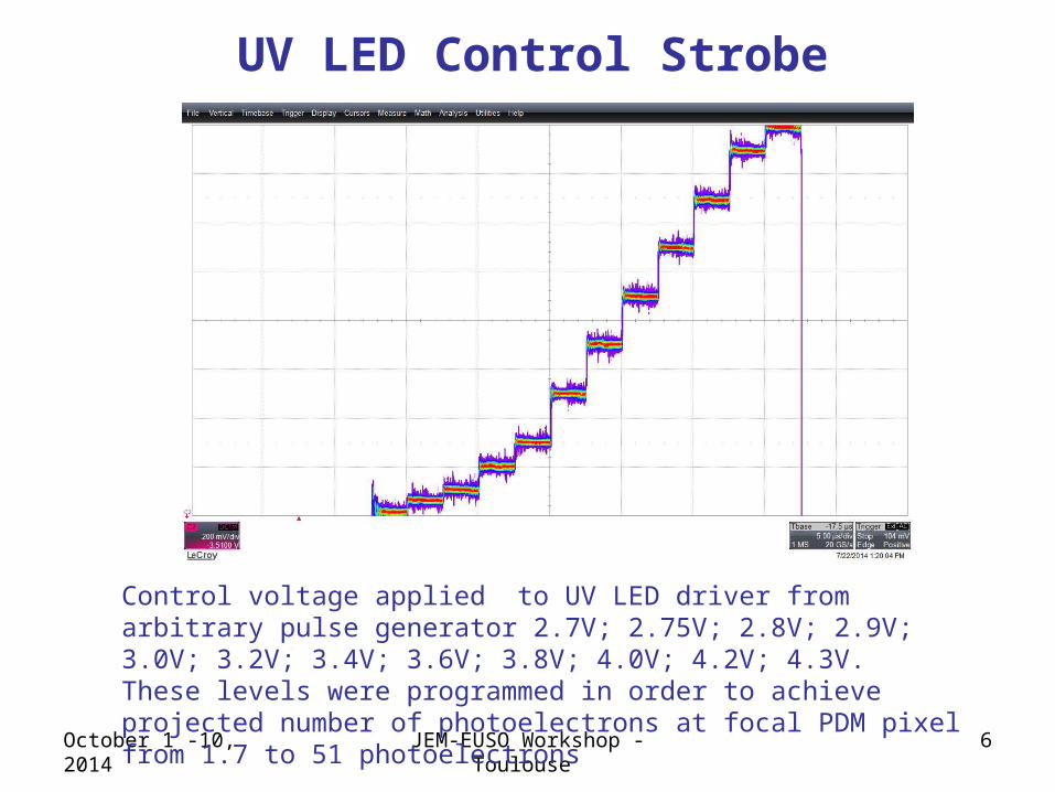
Control voltage applied to UV LED driver from arbitrary pulse generator 2.7V; 2.75V; 2.8V; 2.9V; 3.0V; 3.2V; 3.4V; 3.6V; 3.8V; 4.0V; 4.2V; 4.3V.These levels were programmed in order to achieve projected number of photoelectrons at focal PDM pixel from 1.7 to 51 photoelectrons
UV LED Control Strobe
October 1 -10, 2014 JEM-EUSO Workshop - Toulouse 7
UV LED Calibration Characteristics
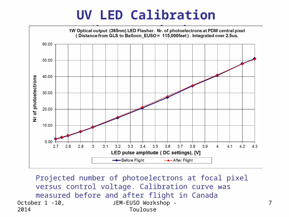
Projected number of photoelectrons at focal pixel versus control voltage. Calibration curve was measured before and after flight in Canada
October 1 -10, 2014 JEM-EUSO Workshop - Toulouse 8
Calibration of the Xenon Flasher
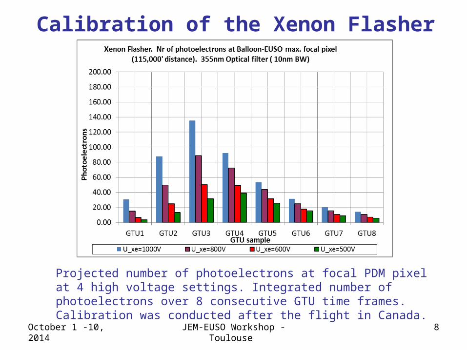
Projected number of photoelectrons at focal PDM pixel at 4 high voltage settings. Integrated number of photoelectrons over 8 consecutive GTU time frames. Calibration was conducted after the flight in Canada.
October 1 -10, 2014 JEM-EUSO Workshop - Toulouse 9
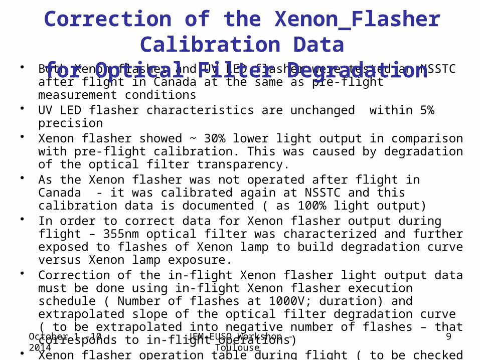
• Both Xenon flasher and UV LED flasher were tested an NSSTC after flight in Canada at the same as pre-flight measurement conditions
• UV LED flasher characteristics are unchanged within 5% precision• Xenon flasher showed ~ 30% lower light output in comparison with pre-flight
calibration. This was caused by degradation of the optical filter transparency.• As the Xenon flasher was not operated after flight in Canada - it was calibrated
again at NSSTC and this calibration data is documented ( as 100% light output)• In order to correct data for Xenon flasher output during flight – 355nm optical
filter was characterized and further exposed to flashes of Xenon lamp to build degradation curve versus Xenon lamp exposure.
• Correction of the in-flight Xenon flasher light output data must be done using in-flight Xenon flasher execution schedule ( Number of flashes at 1000V; duration) and extrapolated slope of the optical filter degradation curve ( to be extrapolated into negative number of flashes – that corresponds to in-flight operations)
• Xenon flasher operation table during flight ( to be checked / corrected) was created, using comments from Johannes Eser and temperature log data (temperature/humidity loggers recorded environment data in both HV Power Supply and in Xenon Lamp boxes during the whole campaign.
Correction of the Xenon_Flasher Calibration Datafor Optical Filter Degradation
October 1 -10, 2014 JEM-EUSO Workshop - Toulouse 10
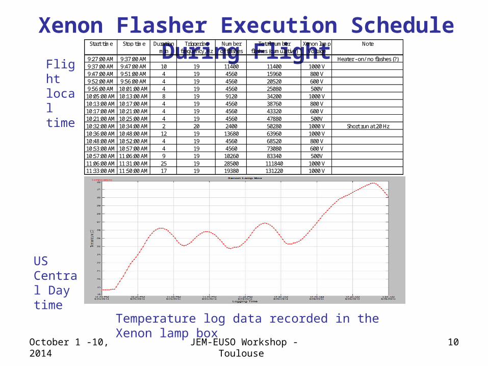
Start time Stop time Duration Triggering Number Total number Xenon lamp Notemin frequency, Hz of flashes flashes (cumulative) Voltage
9:27:00 AM 9:37:00 AM Heater - on/ no flashes (?)9:37:00 AM 9:47:00 AM 10 19 11400 11400 1000 V9:47:00 AM 9:51:00 AM 4 19 4560 15960 800 V9:52:00 AM 9:56:00 AM 4 19 4560 20520 600 V9:56:00 AM 10:01:00 AM 4 19 4560 25080 500V
10:05:00 AM 10:13:00 AM 8 19 9120 34200 1000 V10:13:00 AM 10:17:00 AM 4 19 4560 38760 800 V10:17:00 AM 10:21:00 AM 4 19 4560 43320 600 V10:21:00 AM 10:25:00 AM 4 19 4560 47880 500V10:32:00 AM 10:34:00 AM 2 20 2400 50280 1000 V Short run at 20 Hz10:36:00 AM 10:48:00 AM 12 19 13680 63960 1000 V10:48:00 AM 10:52:00 AM 4 19 4560 68520 800 V10:53:00 AM 10:57:00 AM 4 19 4560 73080 600 V10:57:00 AM 11:06:00 AM 9 19 10260 83340 500V11:06:00 AM 11:31:00 AM 25 19 28500 111840 1000 V11:33:00 AM 11:50:00 AM 17 19 19380 131220 1000 V
Xenon Flasher Execution Schedule During Flight
Temperature log data recorded in the Xenon lamp box
Flight local time
US Central Day time
October 1 -10, 2014 JEM-EUSO Workshop - Toulouse 11
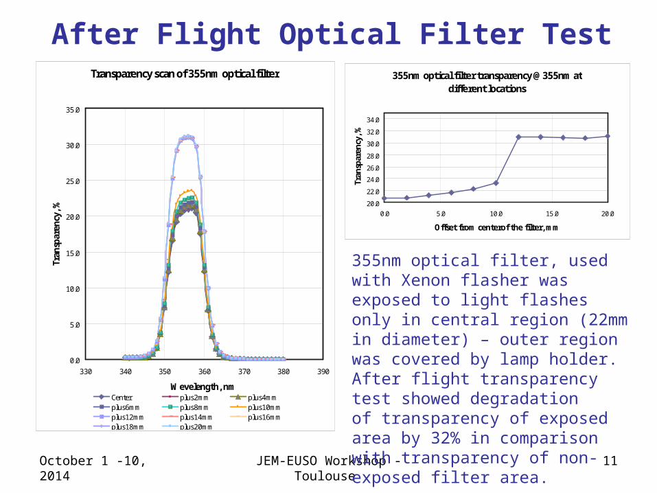
Transparency scan of 355nm optical filter
0.0
5.0
10.0
15.0
20.0
25.0
30.0
35.0
330 340 350 360 370 380 390
Wevelength, nm
Tran
spar
ency
, %
Center plus2mm plus4mmplus6mm plus8mm plus10mmplus12mm plus14mm plus16mmplus18mm plus20mm
355nm optical filter transparency @355nm at different locations
20.0
22.0
24.0
26.0
28.0
30.0
32.0
34.0
0.0 5.0 10.0 15.0 20.0
Offset from centerof the filter, mm
Tran
spar
ency
, %
After Flight Optical Filter Test
355nm optical filter, used with Xenon flasher was exposed to light flashes only in central region (22mm in diameter) – outer region was covered by lamp holder. After flight transparency test showed degradationof transparency of exposed area by 32% in comparison with transparency of non-exposed filter area.
Exposed filter area
Non-exposed area
October 1 -10, 2014 JEM-EUSO Workshop - Toulouse 12
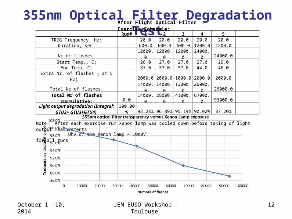
355nm Optical Filter Degradation TestAfter Flight Optical Filter Exercise Schedule:
Run# 1 2 3 4 5 TRIG Frequency, Hz: 20.0 20.0 20.0 20.0 20.0
Duration, sec: 600.0 600.0 600.0 1200.0 1200.0 Nr of flashes: 12000.0 12000.0 12000.0 24000.0 24000.0
Start Temp., C: 26.0 27.0 27.0 27.0 29.0 End Temp, C: 37.0 37.0 37.0 44.0 46.0
Extra Nr. of flashes ( at 5 Hz) : 2000.0 2000.0 1000.0 2000.0 2000.0 Total Nr of flashes: 14000.0 14000.0 13000.0 26000.0 26000.0
Total Nr of flashes cummulative: 0.0 14000.0 28000.0 41000.0 67000.0 93000.0
Light output degradation (Integral: GTU2+ GTU3+GTU4) 100.00% 98.28% 96.89% 95.19% 90.02% 87.20%
Note: After each exercise run Xenon lamp was cooled down before taking of light output measurements Uhv of the Xenon lamp = 1000V for all runs
October 1 -10, 2014 JEM-EUSO Workshop - Toulouse 13
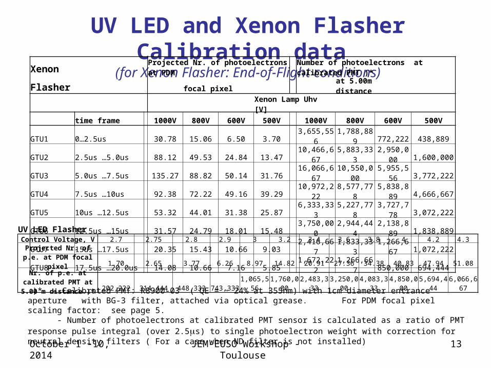
UV LED and Xenon Flasher Calibration data (for Xenon Flasher: End-of-Flight conditions)
)* - Calibrated PMT: R8900-03 ( QE = ~ 24% at 355nm) with 1cm diameter entrance aperture with BG-3 filter, attached via optical grease. For PDM focal pixel scaling factor: see page 5. - Number of photoelectrons at calibrated PMT sensor is calculated as a ratio of PMT response pulse integral (over 2.5ms) to single photoelectron weight with correction for neutral density filters ( For a case when ND filter is not installed)
UV LED FlasherControl Voltage, V 2.7 2.75 2.8 2.9 3 3.2 3.4 3.6 3.8 4 4.2 4.3
Projected Nr. of p.e. at PDM focal pixel 1.70 2.65 3.77 6.26 8.97 14.82 20.91 27.36 34.38 40.83 47.94 51.08
Nr. of p.e. at calibrated PMT at 5.00 m distance )* 202,222 314,444 448,333 743,333 1,065,556 1,760,000 2,483,333 3,250,000 4,083,333 4,850,000 5,694,444 6,066,667
Xenon Projected Nr. of photoelectrons at PDM Number of photoelectrons at calibrated PMT )*
Flasher focal pixel at 5.00m distance
Xenon Lamp Uhv [V]
time frame 1000V 800V 600V 500V 1000V 800V 600V 500V
GTU1 0…2.5us 30.78 15.06 6.50 3.70 3,655,556 1,788,889 772,222 438,889
GTU2 2.5us …5.0us 88.12 49.53 24.84 13.47 10,466,667 5,883,333 2,950,000 1,600,000
GTU3 5.0us …7.5us 135.27 88.82 50.14 31.76 16,066,667 10,550,000 5,955,556 3,772,222
GTU4 7.5us …10us 92.38 72.22 49.16 39.29 10,972,222 8,577,778 5,838,889 4,666,667
GTU5 10us …12.5us 53.32 44.01 31.38 25.87 6,333,333 5,227,778 3,727,778 3,072,222
GTU6 12.5us …15us 31.57 24.79 18.01 15.48 3,750,000 2,944,444 2,138,889 1,838,889
GTU7 15us …17.5us 20.35 15.43 10.66 9.03 2,416,667 1,833,333 1,266,667 1,072,222
GTU8 17.5us …20.0us 14.08 10.66 7.16 5.85 1,672,222 1,266,667 850,000 694,444
October 1 -10, 2014 JEM-EUSO Workshop - Toulouse 14
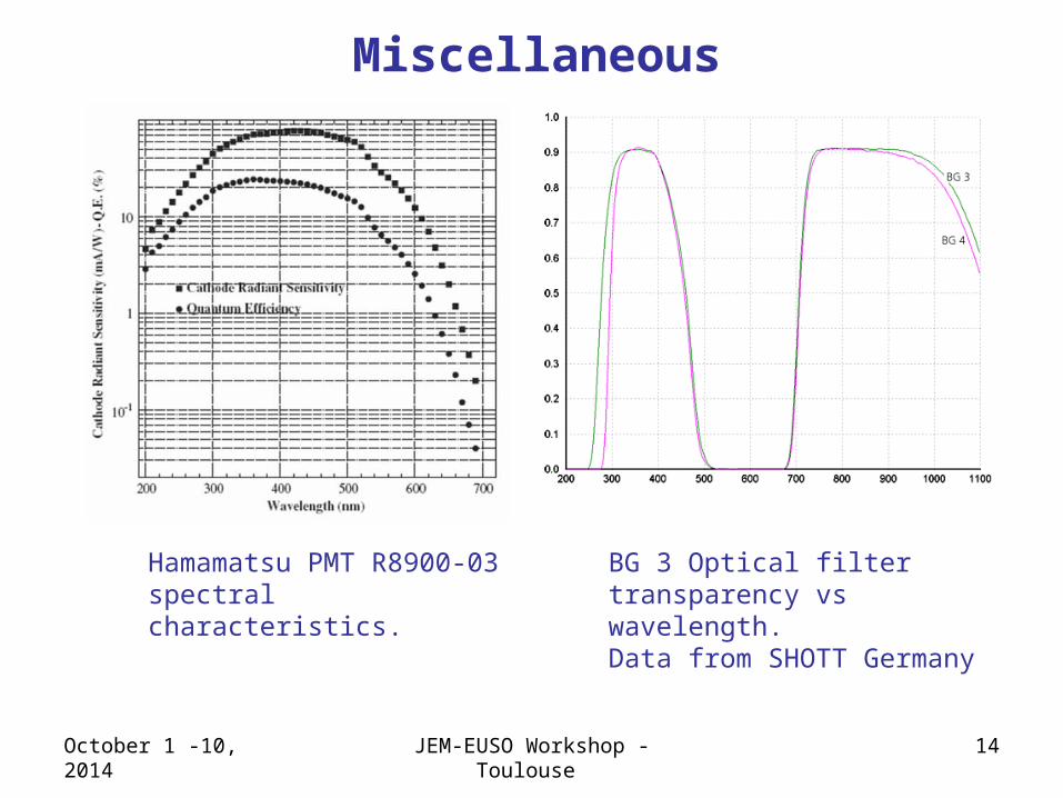
Miscellaneous
BG 3 Optical filter transparency vs wavelength.Data from SHOTT Germany
Hamamatsu PMT R8900-03 spectral characteristics.
October 1 -10, 2014 JEM-EUSO Workshop - Toulouse 15
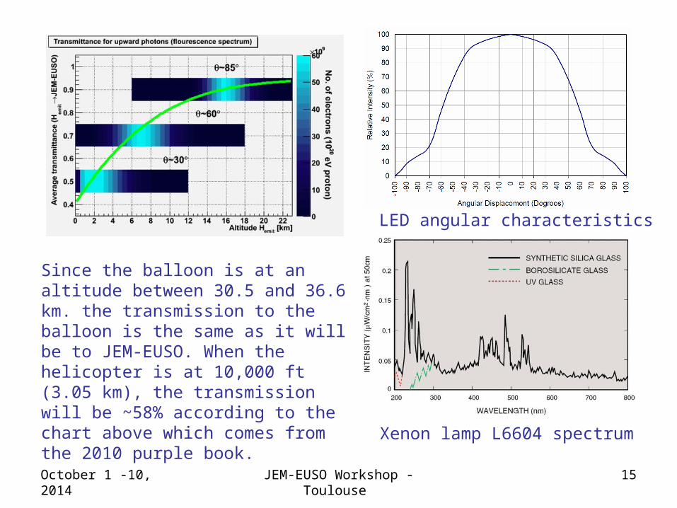
LED angular characteristics
Xenon lamp L6604 spectrum
Since the balloon is at an altitude between 30.5 and 36.6 km. the transmission to the balloon is the same as it will be to JEM-EUSO. When the helicopter is at 10,000 ft (3.05 km), the transmission will be ~58% according to the chart above which comes from the 2010 purple book.