Embed Size (px)
Citation preview
Basic Computer Organization
Chapter 2S. Dandamudi
Outline
• Basic components• The processor
– Execution cycle– System clock
• Number of addresses– 3-address machines– 2-address machines– 1-address machines– 0-address machines– Load/store architecture
• Flow control– Branching– Procedure calls
• Memory– Basic operations– Types of memory– Storing multibyte data
• Input/Output• Performance: Data
alignment
2005
To be used with S. Dandamudi,
“Introduction to Assembly
Language Programming,”
Second Edition, Springer,
2005.
S. Dandamudi Chapter 2: Page 2

Basic Components
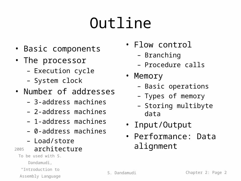
• Basic components of a computer system– Processor– Memory– I/O– System bus
• Address bus• Data bus• Control bus
2005
To be used with S. Dandamudi,
“Introduction to Assembly
Language Programming,”
Second Edition, Springer,
2005.
S. Dandamudi Chapter 2: Page 3
Basic Components (cont’d)
2005
To be used with S. Dandamudi,
“Introduction to Assembly
Language Programming,”
Second Edition, Springer,
2005.
S. Dandamudi Chapter 2: Page 4
The Processor
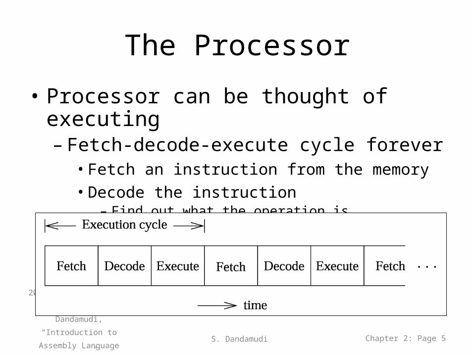
• Processor can be thought of executing – Fetch-decode-execute cycle forever
• Fetch an instruction from the memory• Decode the instruction
– Find out what the operation is
• Execute the instruction– Perform the specified operation
2005
To be used with S. Dandamudi,
“Introduction to Assembly
Language Programming,”
Second Edition, Springer,
2005.
S. Dandamudi Chapter 2: Page 5
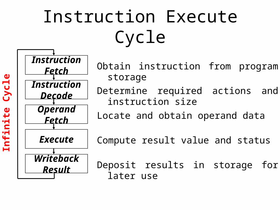
Instruction Execute Cycle
Obtain instruction from program storage
Determine required actions and instruction size
Locate and obtain operand data
Compute result value and status
Deposit results in storage for later use
InstructionDecode
InstructionFetch
OperandFetch
Execute
WritebackResult
Infi
nit
e C
ycle
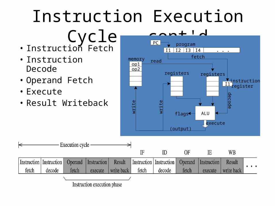
Instruction Execution Cycle – cont'd• Instruction Fetch• Instruction Decode• Operand Fetch• Execute • Result Writeback
I2 I3 I4
PC program
I1instructionregister
op1op2
memory fetch
ALU
registers
wri
te
decode
execute
read
wri
te
(output)
registers
flags
. . .I1
The Processor (cont’d)
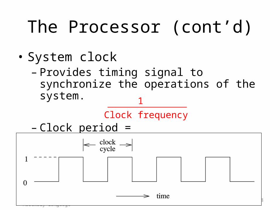
• System clock– Provides timing signal to synchronize the
operations of the system.
– Clock period = (instruction execution time)
2005
To be used with S. Dandamudi,
“Introduction to Assembly
Language Programming,”
Second Edition, Springer,
2005.
S. Dandamudi Chapter 2: Page 8
1
Clock frequency
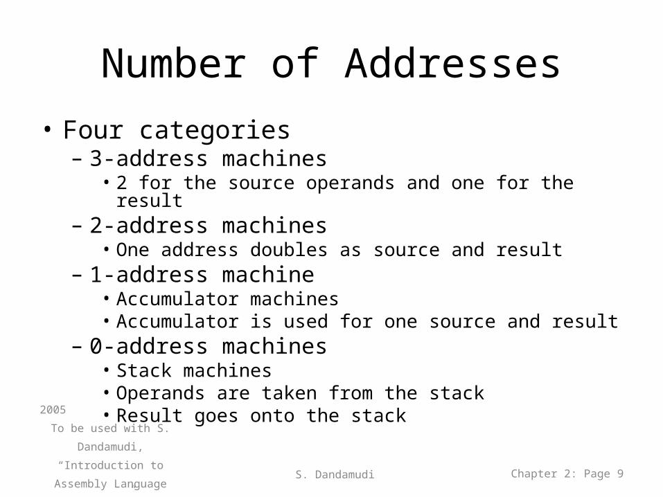
Number of Addresses• Four categories
– 3-address machines• 2 for the source operands and one for the result
– 2-address machines• One address doubles as source and result
– 1-address machine• Accumulator machines• Accumulator is used for one source and result
– 0-address machines• Stack machines• Operands are taken from the stack• Result goes onto the stack2005
To be used with S. Dandamudi,
“Introduction to Assembly
Language Programming,”
Second Edition, Springer,
2005.
S. Dandamudi Chapter 2: Page 9
Number of Addresses (cont’d)
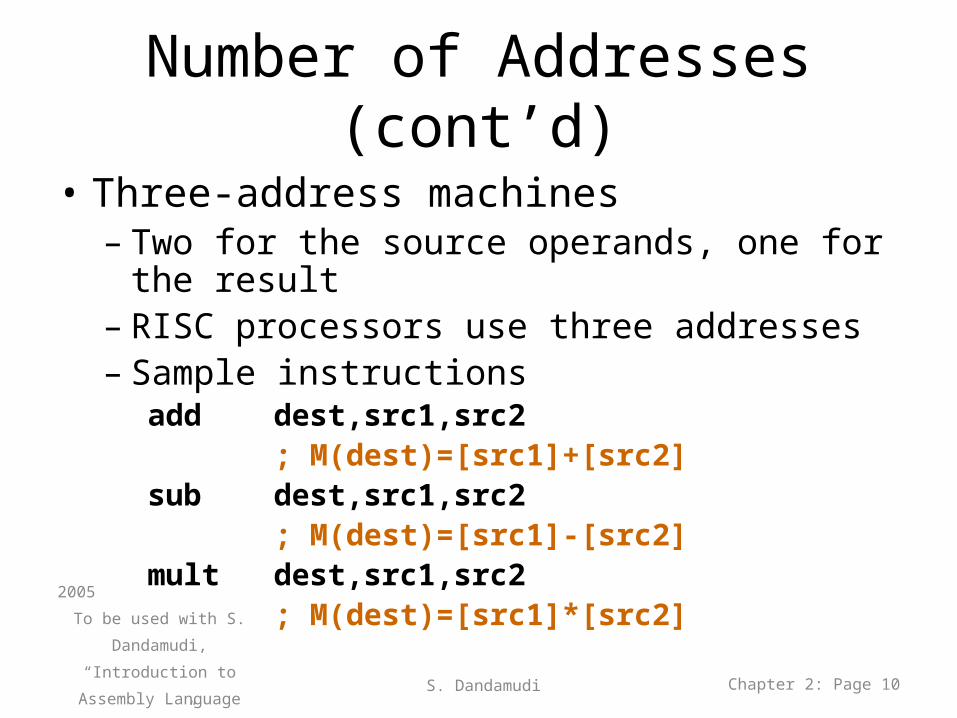
• Three-address machines– Two for the source operands, one for the result– RISC processors use three addresses– Sample instructions
add dest,src1,src2 ; M(dest)=[src1]+[src2] sub dest,src1,src2 ; M(dest)=[src1]-[src2] mult dest,src1,src2 ; M(dest)=[src1]*[src2]
2005
To be used with S. Dandamudi,
“Introduction to Assembly
Language Programming,”
Second Edition, Springer,
2005.
S. Dandamudi Chapter 2: Page 10
Number of Addresses (cont’d)
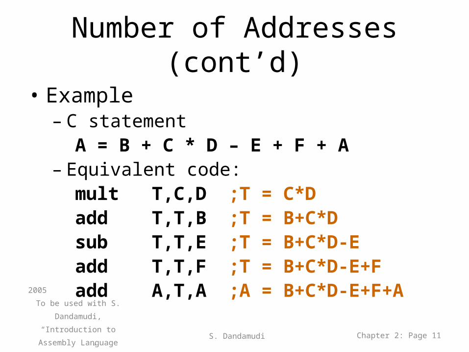
• Example– C statement
A = B + C * D – E + F + A– Equivalent code:
mult T,C,D ;T = C*Dadd T,T,B ;T = B+C*Dsub T,T,E ;T = B+C*D-Eadd T,T,F ;T = B+C*D-E+Fadd A,T,A ;A = B+C*D-E+F+A
2005
To be used with S. Dandamudi,
“Introduction to Assembly
Language Programming,”
Second Edition, Springer,
2005.
S. Dandamudi Chapter 2: Page 11
Number of Addresses (cont’d)
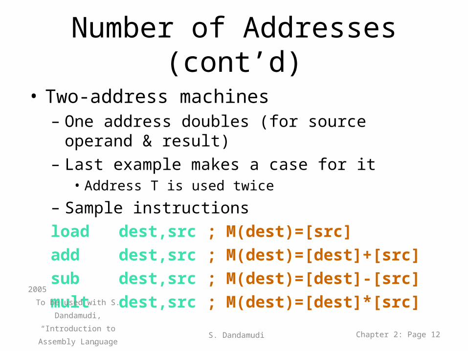
• Two-address machines– One address doubles (for source operand & result)– Last example makes a case for it
• Address T is used twice
– Sample instructionsload dest,src ; M(dest)=[src]
add dest,src ; M(dest)=[dest]+[src]
sub dest,src ; M(dest)=[dest]-[src]
mult dest,src ; M(dest)=[dest]*[src]2005
To be used with S. Dandamudi,
“Introduction to Assembly
Language Programming,”
Second Edition, Springer,
2005.
S. Dandamudi Chapter 2: Page 12
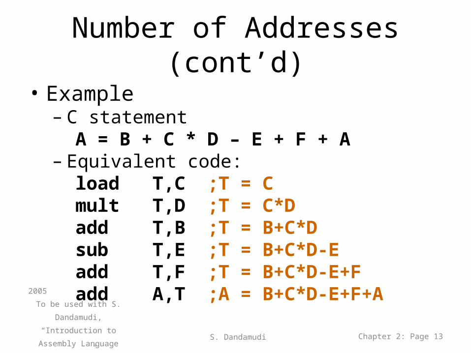
Number of Addresses (cont’d)
• Example– C statement
A = B + C * D – E + F + A– Equivalent code:
load T,C ;T = Cmult T,D ;T = C*Dadd T,B ;T = B+C*Dsub T,E ;T = B+C*D-Eadd T,F ;T = B+C*D-E+Fadd A,T ;A = B+C*D-E+F+A
2005
To be used with S. Dandamudi,
“Introduction to Assembly
Language Programming,”
Second Edition, Springer,
2005.
S. Dandamudi Chapter 2: Page 13
Number of Addresses (cont’d)
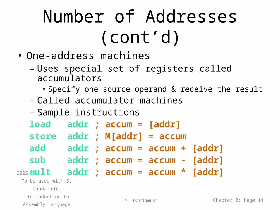
• One-address machines– Uses special set of registers called accumulators
• Specify one source operand & receive the result– Called accumulator machines– Sample instructionsload addr ; accum = [addr] store addr ; M[addr] = accum add addr ; accum = accum + [addr] sub addr ; accum = accum - [addr] mult addr ; accum = accum * [addr]
2005
To be used with S. Dandamudi,
“Introduction to Assembly
Language Programming,”
Second Edition, Springer,
2005.
S. Dandamudi Chapter 2: Page 14
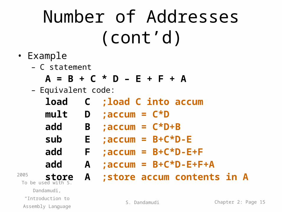
Number of Addresses (cont’d)• Example
– C statement
A = B + C * D – E + F + A– Equivalent code:
load C ;load C into accummult D ;accum = C*Dadd B ;accum = C*D+Bsub E ;accum = B+C*D-Eadd F ;accum = B+C*D-E+Fadd A ;accum = B+C*D-E+F+Astore A ;store accum contents in A
2005
To be used with S. Dandamudi,
“Introduction to Assembly
Language Programming,”
Second Edition, Springer,
2005.
S. Dandamudi Chapter 2: Page 15
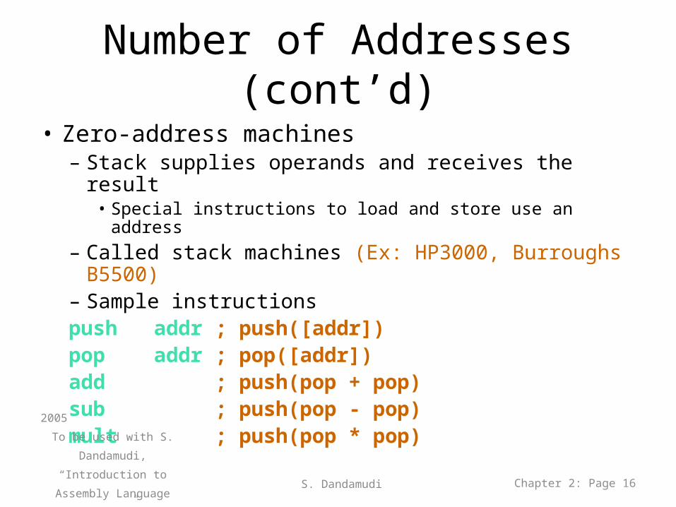
Number of Addresses (cont’d)
• Zero-address machines– Stack supplies operands and receives the result
• Special instructions to load and store use an address– Called stack machines (Ex: HP3000, Burroughs B5500)– Sample instructionspush addr ; push([addr]) pop addr ; pop([addr]) add ; push(pop + pop) sub ; push(pop - pop) mult ; push(pop * pop)
2005
To be used with S. Dandamudi,
“Introduction to Assembly
Language Programming,”
Second Edition, Springer,
2005.
S. Dandamudi Chapter 2: Page 16
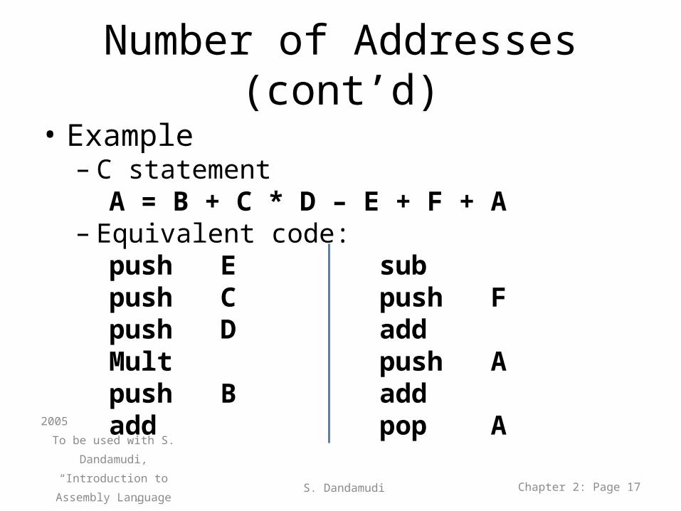
Number of Addresses (cont’d)
• Example– C statement
A = B + C * D – E + F + A– Equivalent code:
push E subpush C push Fpush D addMult push Apush B addadd pop A
2005
To be used with S. Dandamudi,
“Introduction to Assembly
Language Programming,”
Second Edition, Springer,
2005.
S. Dandamudi Chapter 2: Page 17
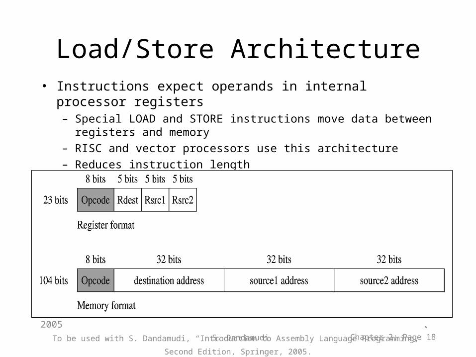
Load/Store Architecture• Instructions expect operands in internal processor registers
– Special LOAD and STORE instructions move data between registers and memory
– RISC and vector processors use this architecture– Reduces instruction length
2005
To be used with S. Dandamudi, “Introduction to Assembly Language Programming,” Second Edition, Springer, 2005. S. Dandamudi Chapter 2: Page 18
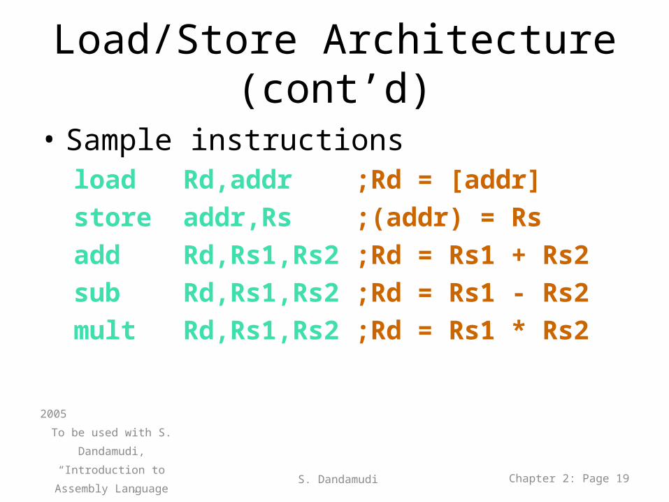
Load/Store Architecture (cont’d)
• Sample instructionsload Rd,addr ;Rd = [addr]
store addr,Rs ;(addr) = Rs
add Rd,Rs1,Rs2 ;Rd = Rs1 + Rs2
sub Rd,Rs1,Rs2 ;Rd = Rs1 - Rs2
mult Rd,Rs1,Rs2 ;Rd = Rs1 * Rs2
2005
To be used with S. Dandamudi,
“Introduction to Assembly
Language Programming,”
Second Edition, Springer,
2005.
S. Dandamudi Chapter 2: Page 19
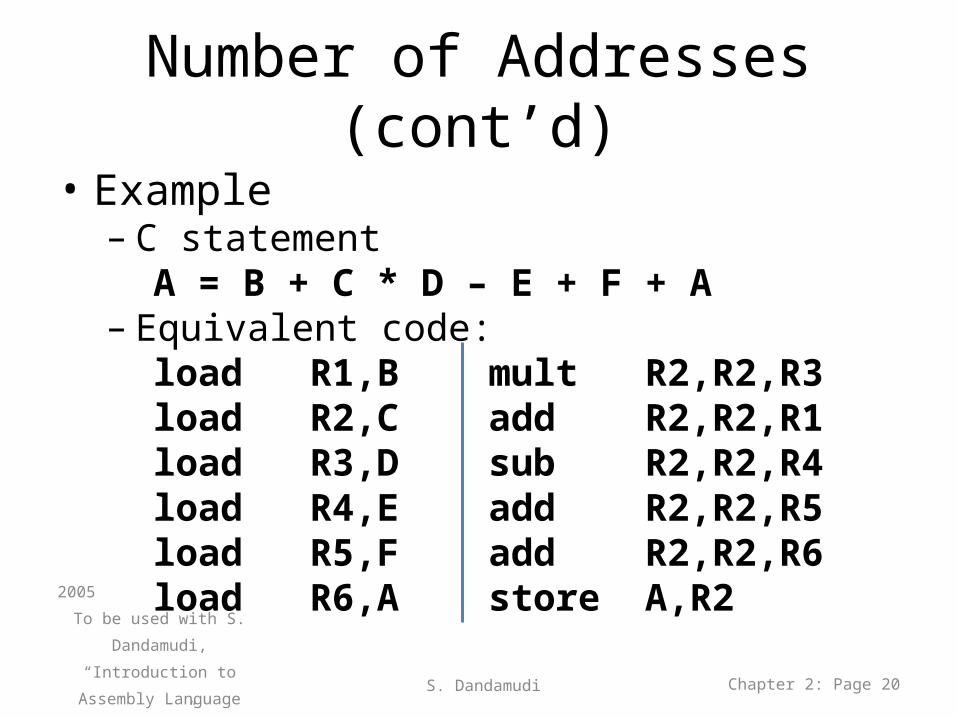
Number of Addresses (cont’d)
• Example– C statement
A = B + C * D – E + F + A– Equivalent code:
load R1,B mult R2,R2,R3load R2,C add R2,R2,R1load R3,D sub R2,R2,R4load R4,E add R2,R2,R5load R5,F add R2,R2,R6load R6,A store A,R2
2005
To be used with S. Dandamudi,
“Introduction to Assembly
Language Programming,”
Second Edition, Springer,
2005.
S. Dandamudi Chapter 2: Page 20
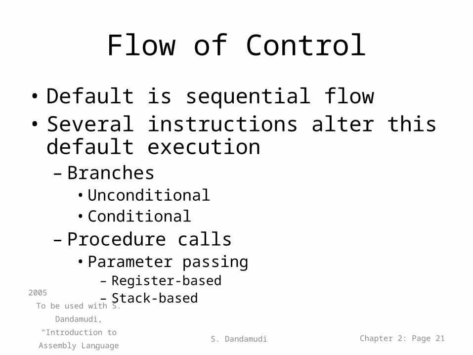
Flow of Control
• Default is sequential flow• Several instructions alter this default
execution– Branches
• Unconditional• Conditional
– Procedure calls• Parameter passing
– Register-based– Stack-based
2005
To be used with S. Dandamudi,
“Introduction to Assembly
Language Programming,”
Second Edition, Springer,
2005.
S. Dandamudi Chapter 2: Page 21
Flow of Control (cont’d)
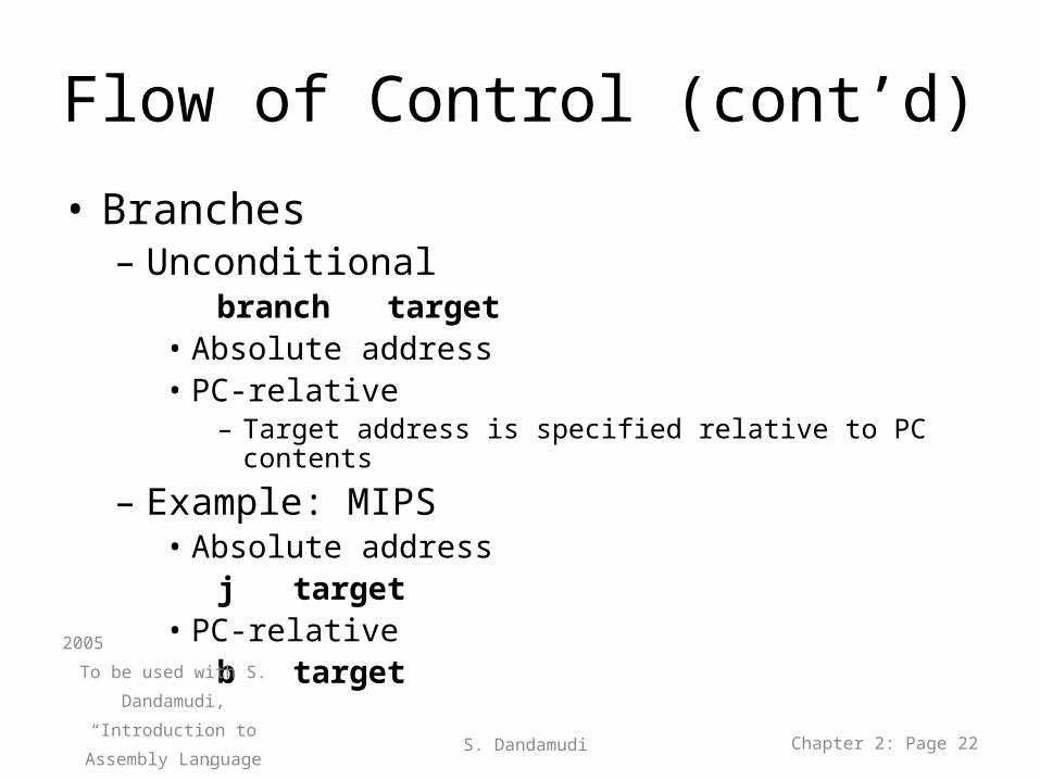
• Branches– Unconditional
branch target• Absolute address• PC-relative
– Target address is specified relative to PC contents
– Example: MIPS• Absolute address
j target• PC-relative
b target2005
To be used with S. Dandamudi,
“Introduction to Assembly
Language Programming,”
Second Edition, Springer,
2005.
S. Dandamudi Chapter 2: Page 22
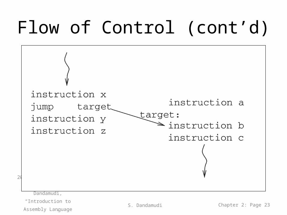
Flow of Control (cont’d)
2005
To be used with S. Dandamudi,
“Introduction to Assembly
Language Programming,”
Second Edition, Springer,
2005.
S. Dandamudi Chapter 2: Page 23
Flow of Control (cont’d)
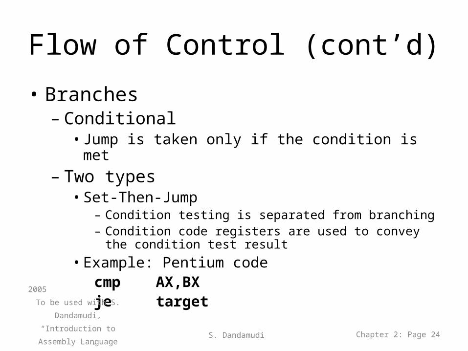
• Branches– Conditional
• Jump is taken only if the condition is met– Two types
• Set-Then-Jump– Condition testing is separated from branching– Condition code registers are used to convey the condition test
result• Example: Pentium code
cmp AX,BXje target2005
To be used with S. Dandamudi,
“Introduction to Assembly
Language Programming,”
Second Edition, Springer,
2005.
S. Dandamudi Chapter 2: Page 24
Flow of Control (cont’d)
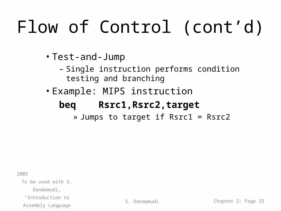
• Test-and-Jump– Single instruction performs condition testing and branching
• Example: MIPS instructionbeq Rsrc1,Rsrc2,target
» Jumps to target if Rsrc1 = Rsrc2
2005
To be used with S. Dandamudi,
“Introduction to Assembly
Language Programming,”
Second Edition, Springer,
2005.
S. Dandamudi Chapter 2: Page 25
Flow of Control (cont’d)
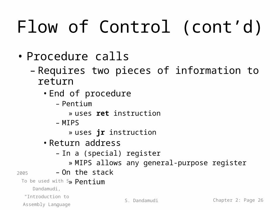
• Procedure calls– Requires two pieces of information to return
• End of procedure– Pentium
» uses ret instruction– MIPS
» uses jr instruction• Return address
– In a (special) register» MIPS allows any general-purpose register
– On the stack» Pentium2005
To be used with S. Dandamudi,
“Introduction to Assembly
Language Programming,”
Second Edition, Springer,
2005.
S. Dandamudi Chapter 2: Page 26
Flow of Control (cont’d)
2005
To be used with S. Dandamudi,
“Introduction to Assembly
Language Programming,”
Second Edition, Springer,
2005.
S. Dandamudi Chapter 2: Page 27
Flow of Control (cont’d)
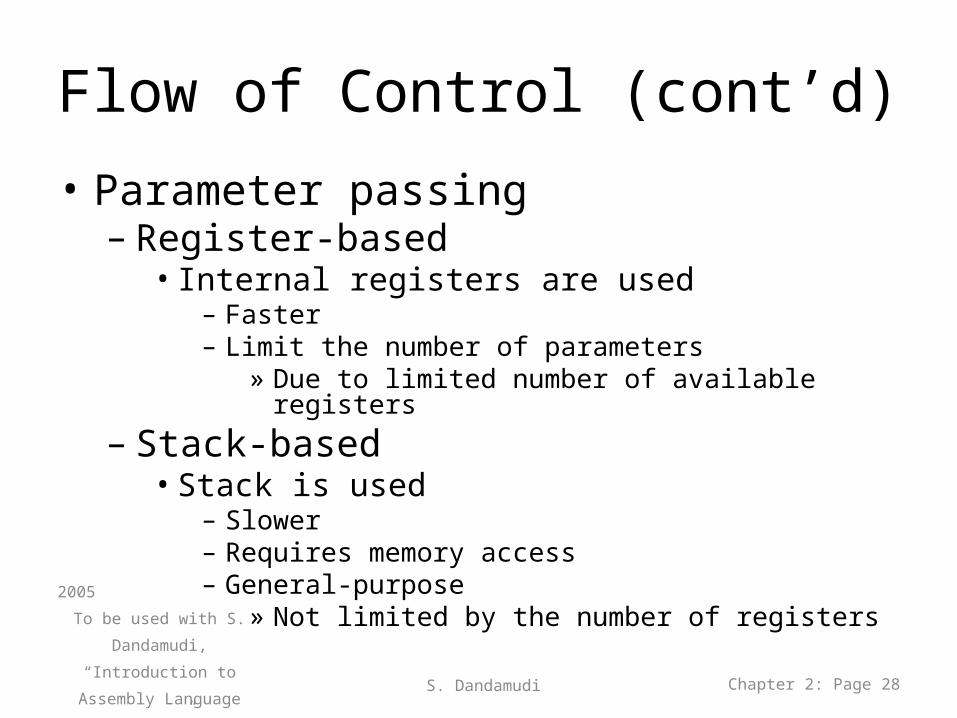
• Parameter passing– Register-based
• Internal registers are used – Faster– Limit the number of parameters
» Due to limited number of available registers
– Stack-based• Stack is used
– Slower– Requires memory access– General-purpose
» Not limited by the number of registers2005
To be used with S. Dandamudi,
“Introduction to Assembly
Language Programming,”
Second Edition, Springer,
2005.
S. Dandamudi Chapter 2: Page 28
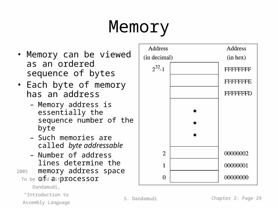
Memory• Memory can be viewed as
an ordered sequence of bytes
• Each byte of memory has an address– Memory address is essentially
the sequence number of the byte
– Such memories are called byte addressable
– Number of address lines determine the memory address space of a processor
2005
To be used with S. Dandamudi,
“Introduction to Assembly
Language Programming,”
Second Edition, Springer,
2005.
S. Dandamudi Chapter 2: Page 29
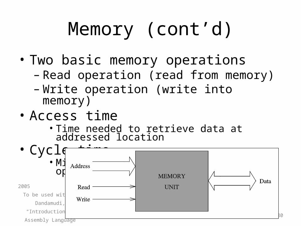
Memory (cont’d)
• Two basic memory operations– Read operation (read from memory)– Write operation (write into memory)
• Access time• Time needed to retrieve data at addressed location
• Cycle time• Minimum time between successive operations
2005
To be used with S. Dandamudi,
“Introduction to Assembly
Language Programming,”
Second Edition, Springer,
2005.
S. Dandamudi Chapter 2: Page 30
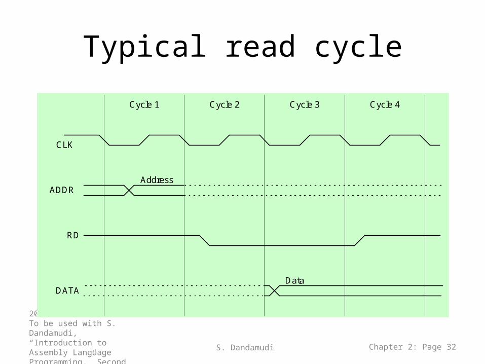
Memory (cont’d)• Steps in a typical read cycle
• Place the address of the location to be read on the address bus
• Activate the memory read control signal on the control bus• Wait for the memory to retrieve the data from the
addressed memory location• Read the data from the data bus• Drop the memory read control signal to terminate the read
cycle– A simple Pentium memory read cycle takes 3 clocks
– Steps 1&2 and 4&5 are done in one clock cycle each– For slower memories, wait cycles will have to be
inserted2005
To be used with S. Dandamudi,
“Introduction to Assembly
Language Programming,”
Second Edition, Springer,
2005.
S. Dandamudi Chapter 2: Page 31
Typical read cycle
2005To be used with S. Dandamudi, “Introduction to Assembly Language Programming,” Second Edition, Springer, 2005.
S. Dandamudi Chapter 2: Page 32
Cycle 1 Cycle 2 Cycle 3 Cycle 4
Data
Address
CLK
ADDR
RD
DATA
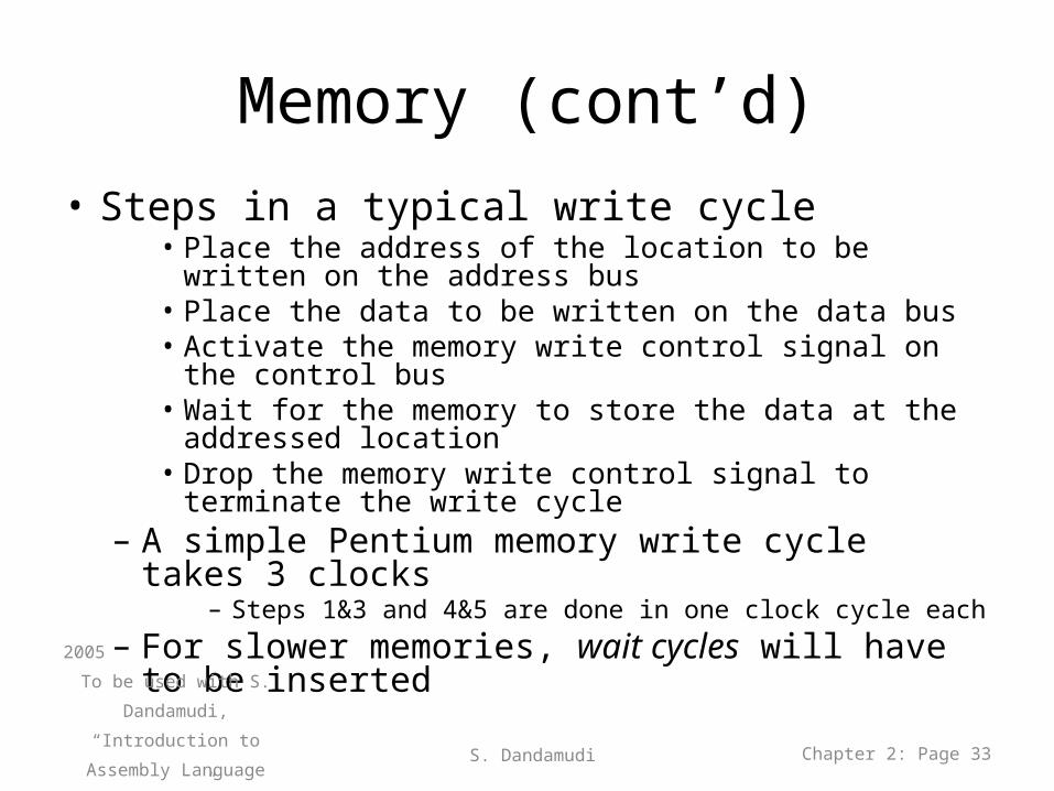
Memory (cont’d)• Steps in a typical write cycle
• Place the address of the location to be written on the address bus
• Place the data to be written on the data bus• Activate the memory write control signal on the control bus• Wait for the memory to store the data at the addressed
location• Drop the memory write control signal to terminate the write
cycle– A simple Pentium memory write cycle takes 3 clocks
– Steps 1&3 and 4&5 are done in one clock cycle each– For slower memories, wait cycles will have to be
inserted2005
To be used with S. Dandamudi,
“Introduction to Assembly
Language Programming,”
Second Edition, Springer,
2005.
S. Dandamudi Chapter 2: Page 33
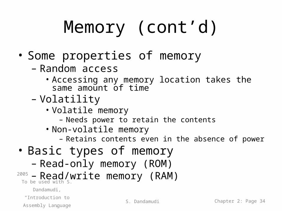
Memory (cont’d)• Some properties of memory
– Random access• Accessing any memory location takes the same amount of
time– Volatility
• Volatile memory– Needs power to retain the contents
• Non-volatile memory– Retains contents even in the absence of power
• Basic types of memory– Read-only memory (ROM)– Read/write memory (RAM)
2005
To be used with S. Dandamudi,
“Introduction to Assembly
Language Programming,”
Second Edition, Springer,
2005.
S. Dandamudi Chapter 2: Page 34
Memory (cont’d)
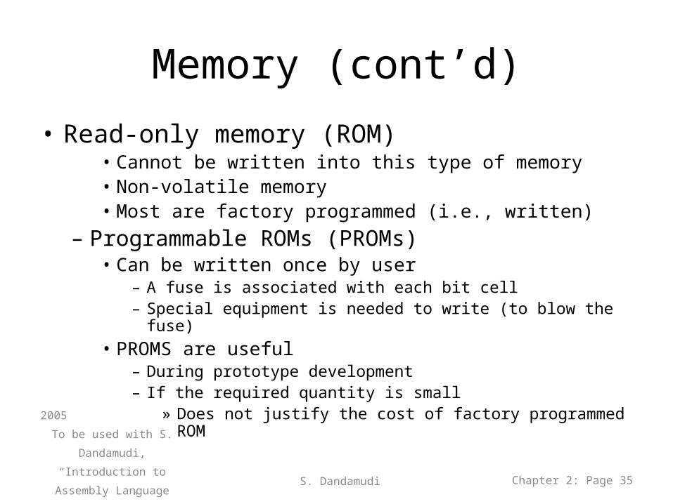
• Read-only memory (ROM)• Cannot be written into this type of memory• Non-volatile memory• Most are factory programmed (i.e., written)
– Programmable ROMs (PROMs)• Can be written once by user
– A fuse is associated with each bit cell– Special equipment is needed to write (to blow the fuse)
• PROMS are useful– During prototype development– If the required quantity is small
» Does not justify the cost of factory programmed ROM 2005
To be used with S. Dandamudi,
“Introduction to Assembly
Language Programming,”
Second Edition, Springer,
2005.
S. Dandamudi Chapter 2: Page 35
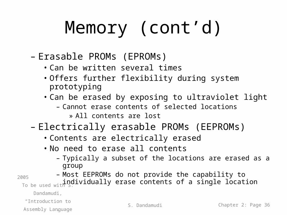
Memory (cont’d)– Erasable PROMs (EPROMs)
• Can be written several times• Offers further flexibility during system prototyping• Can be erased by exposing to ultraviolet light
– Cannot erase contents of selected locations» All contents are lost
– Electrically erasable PROMs (EEPROMs)• Contents are electrically erased• No need to erase all contents
– Typically a subset of the locations are erased as a group– Most EEPROMs do not provide the capability to individually erase
contents of a single location2005
To be used with S. Dandamudi,
“Introduction to Assembly
Language Programming,”
Second Edition, Springer,
2005.
S. Dandamudi Chapter 2: Page 36
Memory (cont’d)
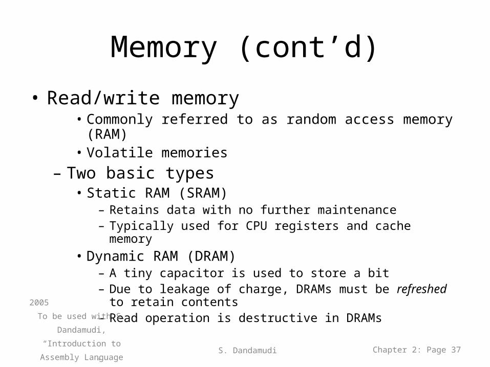
• Read/write memory• Commonly referred to as random access memory (RAM)• Volatile memories
– Two basic types• Static RAM (SRAM)
– Retains data with no further maintenance– Typically used for CPU registers and cache memory
• Dynamic RAM (DRAM)– A tiny capacitor is used to store a bit– Due to leakage of charge, DRAMs must be refreshed to retain
contents– Read operation is destructive in DRAMs
2005
To be used with S. Dandamudi,
“Introduction to Assembly
Language Programming,”
Second Edition, Springer,
2005.
S. Dandamudi Chapter 2: Page 37
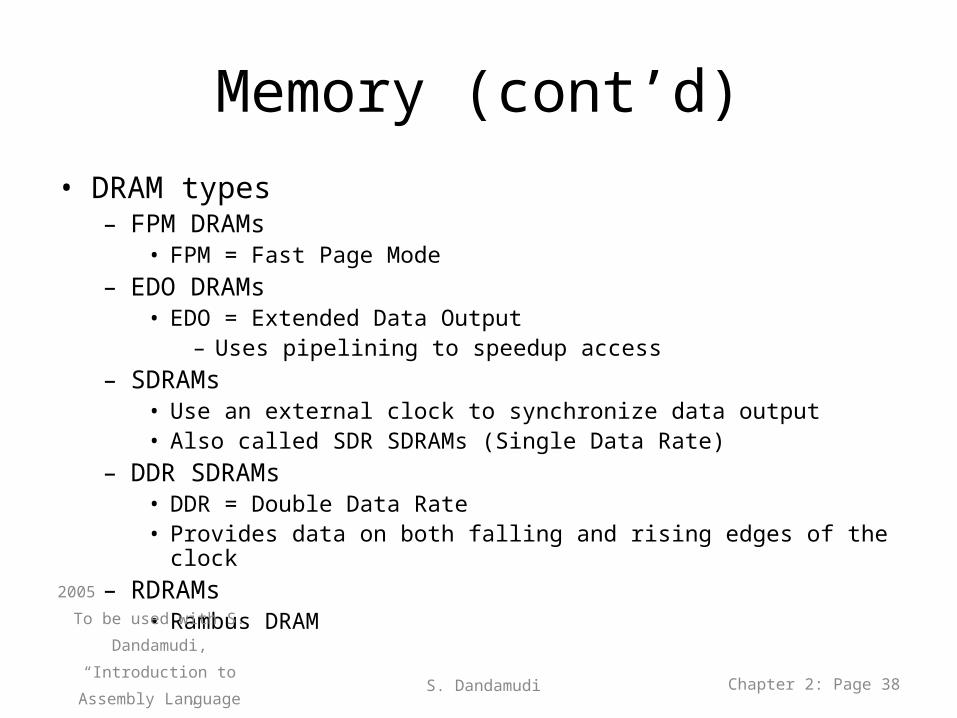
Memory (cont’d)• DRAM types
– FPM DRAMs• FPM = Fast Page Mode
– EDO DRAMs• EDO = Extended Data Output
– Uses pipelining to speedup access– SDRAMs
• Use an external clock to synchronize data output• Also called SDR SDRAMs (Single Data Rate)
– DDR SDRAMs• DDR = Double Data Rate • Provides data on both falling and rising edges of the clock
– RDRAMs• Rambus DRAM2005
To be used with S. Dandamudi,
“Introduction to Assembly
Language Programming,”
Second Edition, Springer,
2005.
S. Dandamudi Chapter 2: Page 38
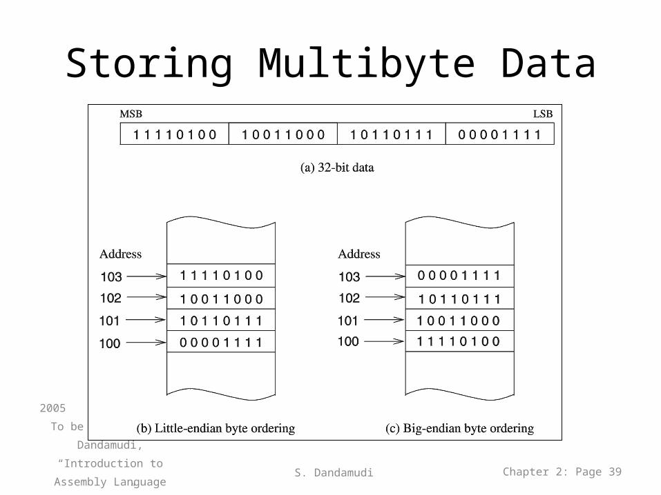
Storing Multibyte Data
2005
To be used with S. Dandamudi,
“Introduction to Assembly
Language Programming,”
Second Edition, Springer,
2005.
S. Dandamudi Chapter 2: Page 39
Storing Multibyte Data (cont’d)• Little endian
• Used by Intel IA-32 processors• Big endian
• Used most processors by default• MIPS supports both byte orderings
• Big endian is the default• Not a problem when working with same type of
machines• Need to convert the format if working with a different
machine• Pentium provides two instructions for conversion
– xchg for 16-bit data– bswap for 32-bit data
2005
To be used with S. Dandamudi,
“Introduction to Assembly
Language Programming,”
Second Edition, Springer,
2005.
S. Dandamudi Chapter 2: Page 40
Input/Output
• Types of I/O Devices:
- Purely input device (e.g., keyboard, mouse). - Purely output device (e.g., printer, display
screen) - Both an input and output device (e.g., Touch
Screens, disks)2005
To be used with S. Dandamudi,
“Introduction to Assembly
Language Programming,”
Second Edition, Springer,
2005.
S. Dandamudi Chapter 2: Page 41
Input/Output Controller
• I/O devices are connected to the system bus via I/O controllers.
• I/O controller acts as an interface between the system and the I/O device.
• I/O controller is used to help the processor to understand and respond to each I/O device.
2005
To be used with S. Dandamudi,
“Introduction to Assembly
Language Programming,”
Second Edition, Springer,
2005.
S. Dandamudi Chapter 2: Page 42
Input/Output Controller
• I/O controller is used for two reasons: 1- To provide the necessary low-level commands and
data for proper operation of the associated I/O device.
2- I/O controller contains driver hardware to send current over long cables that connect the I/O device (i.e. The amount of electrical power used to send signals on the system bus is very low, so we need vary short cable to connect I/O device).
2005
To be used with S. Dandamudi,
“Introduction to Assembly
Language Programming,”
Second Edition, Springer,
2005.
S. Dandamudi Chapter 2: Page 43
Input/Output Controller
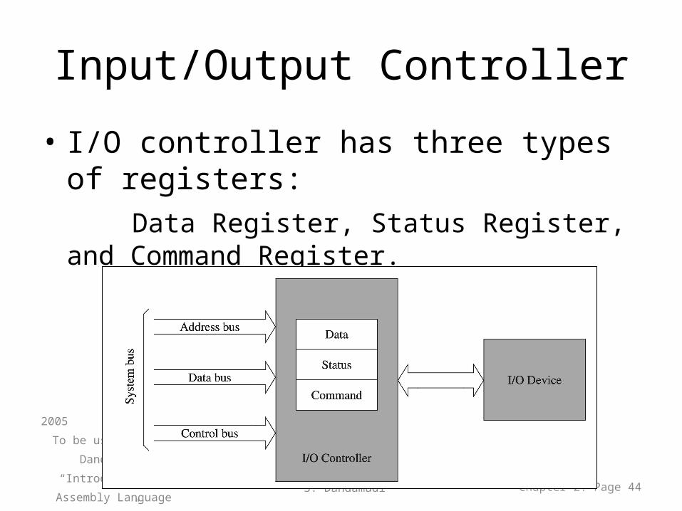
• I/O controller has three types of registers: Data Register, Status Register, and Command
Register.
2005
To be used with S. Dandamudi,
“Introduction to Assembly
Language Programming,”
Second Edition, Springer,
2005.
S. Dandamudi Chapter 2: Page 44
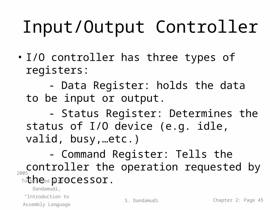
Input/Output Controller
• I/O controller has three types of registers: - Data Register: holds the data to be input or
output. - Status Register: Determines the status of I/O
device (e.g. idle, valid, busy,…etc.) - Command Register: Tells the controller the
operation requested by the processor.
2005
To be used with S. Dandamudi,
“Introduction to Assembly
Language Programming,”
Second Edition, Springer,
2005.
S. Dandamudi Chapter 2: Page 45
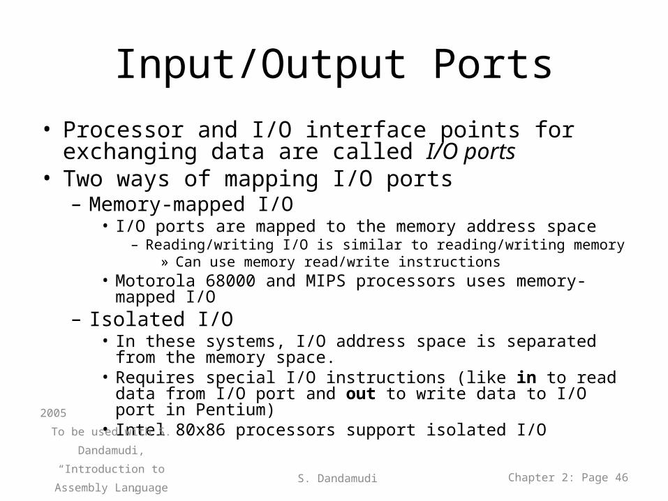
Input/Output Ports• Processor and I/O interface points for exchanging data
are called I/O ports• Two ways of mapping I/O ports
– Memory-mapped I/O• I/O ports are mapped to the memory address space
– Reading/writing I/O is similar to reading/writing memory » Can use memory read/write instructions
• Motorola 68000 and MIPS processors uses memory-mapped I/O– Isolated I/O
• In these systems, I/O address space is separated from the memory space.
• Requires special I/O instructions (like in to read data from I/O port and out to write data to I/O port in Pentium)
• Intel 80x86 processors support isolated I/O2005
To be used with S. Dandamudi,
“Introduction to Assembly
Language Programming,”
Second Edition, Springer,
2005.
S. Dandamudi Chapter 2: Page 46
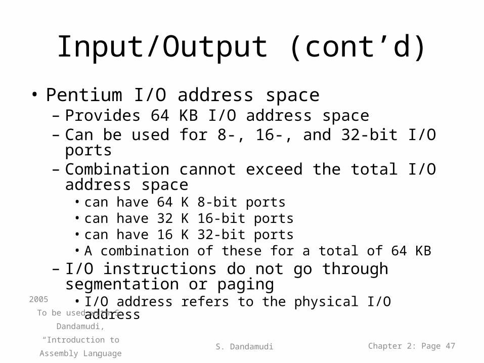
Input/Output (cont’d)• Pentium I/O address space
– Provides 64 KB I/O address space– Can be used for 8-, 16-, and 32-bit I/O ports– Combination cannot exceed the total I/O address
space• can have 64 K 8-bit ports • can have 32 K 16-bit ports• can have 16 K 32-bit ports• A combination of these for a total of 64 KB
– I/O instructions do not go through segmentation or paging
• I/O address refers to the physical I/O address2005
To be used with S. Dandamudi,
“Introduction to Assembly
Language Programming,”
Second Edition, Springer,
2005.
S. Dandamudi Chapter 2: Page 47
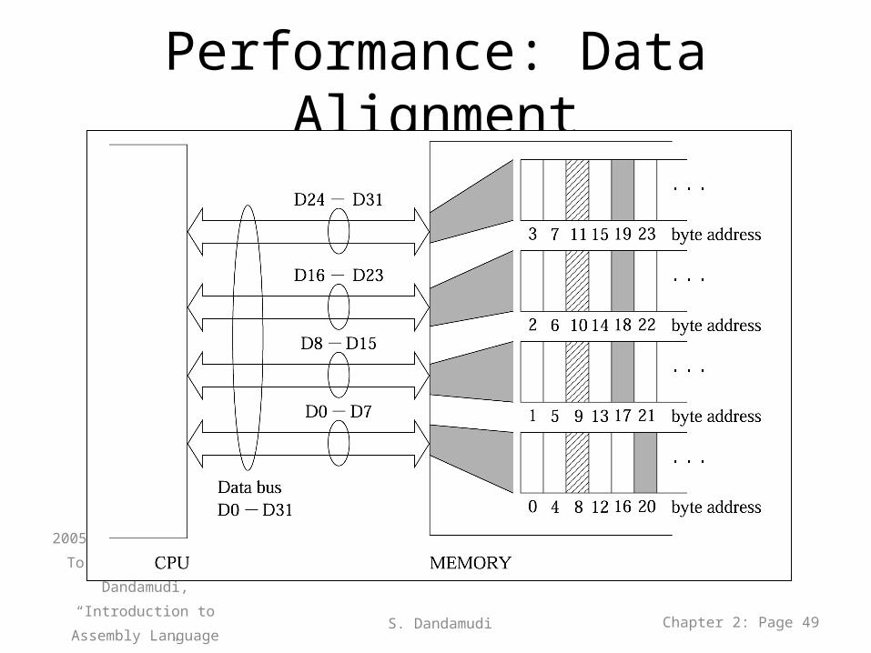
Performance: Data Alignment
• By using Data Alignment: The processor can read data items in one read
cycle, and then internally assemble them.
2005
To be used with S. Dandamudi,
“Introduction to Assembly
Language Programming,”
Second Edition, Springer,
2005.
S. Dandamudi Chapter 2: Page 48
Performance: Data Alignment
2005
To be used with S. Dandamudi,
“Introduction to Assembly
Language Programming,”
Second Edition, Springer,
2005.
S. Dandamudi Chapter 2: Page 49
Performance: Data Alignment (cont’d)
0
1
2
3
5000 10000 15000 20000 25000
Array size
Sort
tim
e (s
econ
ds)
2005
To be used with S. Dandamudi, “Introduction to Assembly Language Programming,” Second Edition, Springer, 2005. S. Dandamudi Chapter 2: Page 50
Unaligned
Aligned
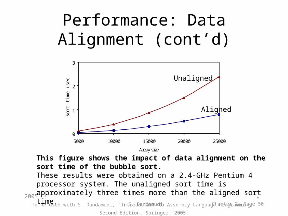
This figure shows the impact of data alignment on the sort time of the bubble sort. These results were obtained on a 2.4-GHz Pentium 4 processor system. The unaligned sort time is approximately three times more than the aligned sort time.
Performance: Data Alignment (cont’d)
• Data alignment– Soft alignment
• Data is not required to be aligned– Data alignment is optional
» Aligned data gives better performance• Used in Intel IA-32 processors
– Hard alignment• Data must be aligned• Used in Motorola 680X0 and Intel i860 processors
2005
To be used with S. Dandamudi,
“Introduction to Assembly
Language Programming,”
Second Edition, Springer,
2005.
S. Dandamudi Chapter 2: Page 51
Performance: Data Alignment (cont’d)
• Data alignment requirements for byte addressable memories– 1-byte data
• Always aligned– 2-byte data
• A 16-bit data item is aligned if the data is stored at an even address (i.e., at an address that is a multiple of 2 and the least significant bit must be 0)
– 4-byte data• A 32-bit data item is aligned if the data is stored at an address that
is a multiple of 4 and the least significant 2 bits must be 0)– 8-byte data
• A 64-bit data item is aligned if the data is stored at an address that is a multiple of 8 and the least significant 3 bits must be 0)2005
To be used with S. Dandamudi,
“Introduction to Assembly
Language Programming,”
Second Edition, Springer,
2005.
S. Dandamudi Chapter 2: Page 52
Last slide