Embed Size (px)
Citation preview
Modified by: Masud-ul-Hasan 1
By Masud-ul-Hasan 1
Chapter 3
Basic Data Communication Technology
By Masud-ul-Hasan 2
Objectives
This chapter deals with the:Physical layerUnshielded Twisted Pair (UTP) and Shielded Twisted Pair (STP)Unshielded Twisted Pair StandardsSignal Degradation
Modified by: Masud-ul-Hasan 2
By Masud-ul-Hasan 3
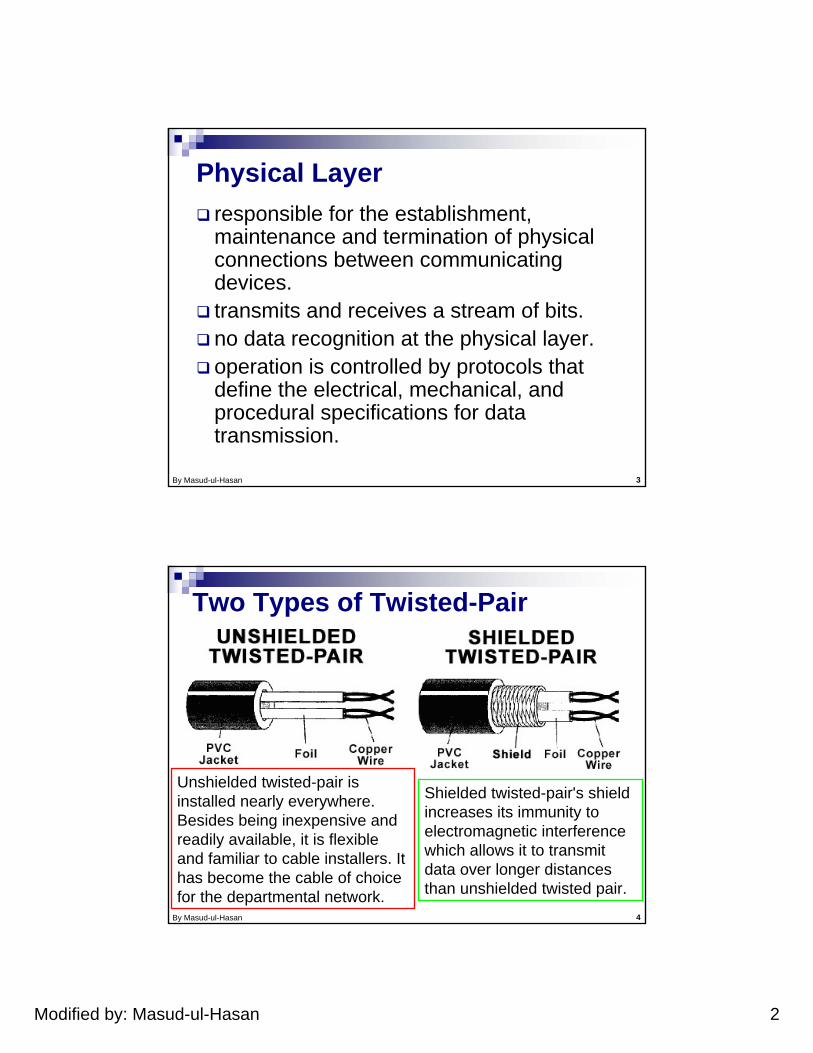
Physical Layerresponsible for the establishment, maintenance and termination of physical connections between communicating devices. transmits and receives a stream of bits. no data recognition at the physical layer. operation is controlled by protocols that define the electrical, mechanical, and procedural specifications for data transmission.
By Masud-ul-Hasan 4
Two Types of Twisted-Pair
Shielded twisted-pair's shield increases its immunity to electromagnetic interference which allows it to transmit data over longer distances than unshielded twisted pair.
Unshielded twisted-pair is installed nearly everywhere. Besides being inexpensive and readily available, it is flexible and familiar to cable installers. It has become the cable of choice for the departmental network.
Modified by: Masud-ul-Hasan 3
By Masud-ul-Hasan 5
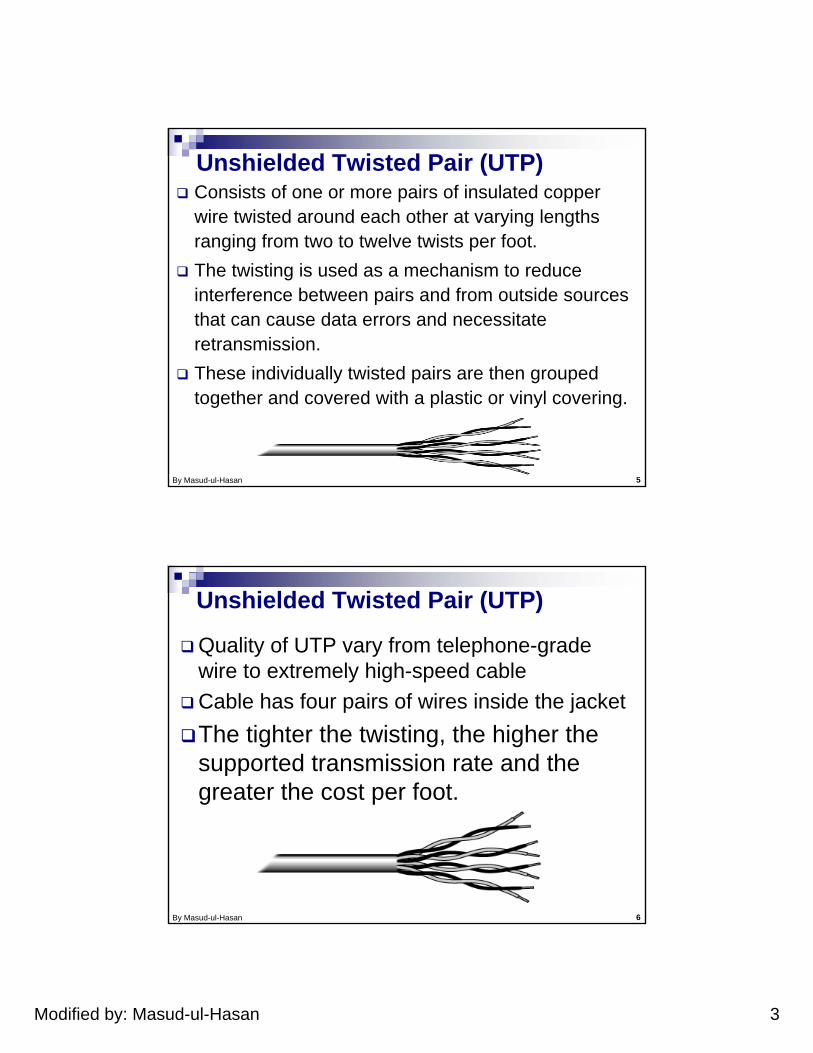
Unshielded Twisted Pair (UTP)Consists of one or more pairs of insulated copper wire twisted around each other at varying lengths ranging from two to twelve twists per foot. The twisting is used as a mechanism to reduce interference between pairs and from outside sources that can cause data errors and necessitate retransmission. These individually twisted pairs are then grouped together and covered with a plastic or vinyl covering.
By Masud-ul-Hasan 6
Unshielded Twisted Pair (UTP)
Quality of UTP vary from telephone-grade wire to extremely high-speed cableCable has four pairs of wires inside the jacketThe tighter the twisting, the higher the supported transmission rate and the greater the cost per foot.
Modified by: Masud-ul-Hasan 4
By Masud-ul-Hasan 7
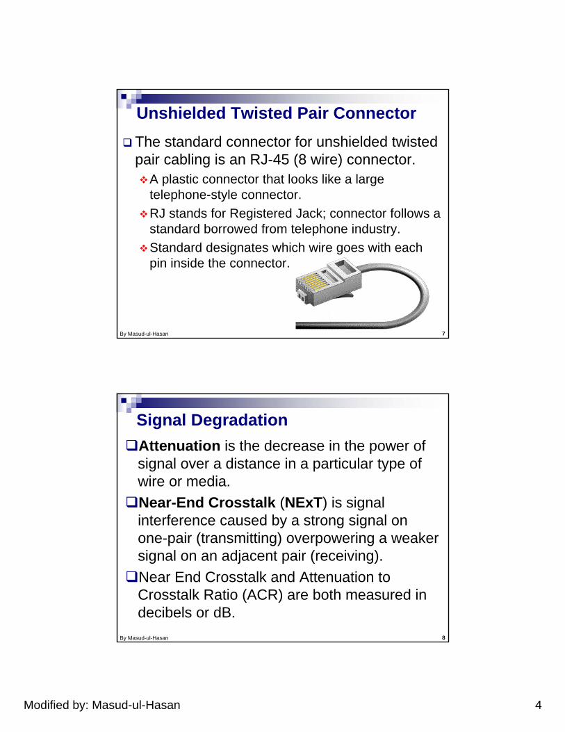
Unshielded Twisted Pair ConnectorThe standard connector for unshielded twisted pair cabling is an RJ-45 (8 wire) connector.
A plastic connector that looks like a large telephone-style connector. RJ stands for Registered Jack; connector follows a standard borrowed from telephone industry.Standard designates which wire goes with each pin inside the connector.
By Masud-ul-Hasan 8
Signal DegradationAttenuation is the decrease in the power of signal over a distance in a particular type of wire or media. Near-End Crosstalk (NExT) is signal interference caused by a strong signal on one-pair (transmitting) overpowering a weaker signal on an adjacent pair (receiving). Near End Crosstalk and Attenuation to Crosstalk Ratio (ACR) are both measured in decibels or dB.
Modified by: Masud-ul-Hasan 5
By Masud-ul-Hasan 9
UTP SpecificationsUTP Category
Maximum Data Speed
Attenuation /NEXT limit Applications
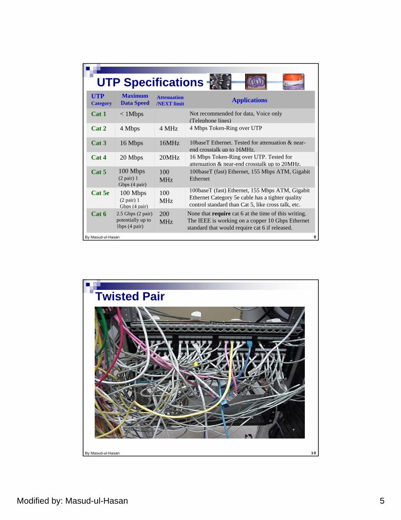
Cat 1 < 1Mbps Not recommended for data, Voice only (Telephone lines)
Cat 2 4 Mbps 4 MHz 4 Mbps Token-Ring over UTP
Cat 3 16 Mbps 16MHz 10baseT Ethernet. Tested for attenuation & near-end crosstalk up to 16MHz.
Cat 4 20 Mbps 20MHz 16 Mbps Token-Ring over UTP. Tested for attenuation & near-end crosstalk up to 20MHz.
Cat 5 100 Mbps(2 pair) 1 Gbps (4 pair)
100 MHz
100baseT (fast) Ethernet, 155 Mbps ATM, Gigabit Ethernet
Cat 5e 100 Mbps(2 pair) 1 Gbps (4 pair)
100 MHz
100baseT (fast) Ethernet, 155 Mbps ATM, Gigabit Ethernet Category 5e cable has a tighter quality control standard than Cat 5, like cross talk, etc.
Cat 6 2.5 Gbps (2 pair) potentially up to 1bps (4 pair)
200 MHz
None that require cat 6 at the time of this writing. The IEEE is working on a copper 10 Gbps Ethernet standard that would require cat 6 if released.
By Masud-ul-Hasan 10
Twisted Pair
Modified by: Masud-ul-Hasan 6
By Masud-ul-Hasan 11
Shielded Twisted Pair (STP)
Shielding is metallic foil or copper braid.Shielded from EMI (Electro-Magnetic Interference) and RFI (Radio-Frequency Interference).Shielding is metal and is therefore a conductor. So shielding is terminated in a drain wire that must be properly grounded.Improperly STP wiring can actually increase rather than decrease interference and data transmission problems.
By Masud-ul-Hasan 12
Coaxial Cable (coax)
Coaxial cable, more commonly known as coax or cable TV cable, has specialized insulators and shielding separating two conductors allowing reliable, high speed data transmission over relatively long distances. Coax comes in various thicknesses and has been historically used in Ethernet network architectures. Modern local area network implementations rarely use coaxial cable today.
Modified by: Masud-ul-Hasan 7
By Masud-ul-Hasan 13
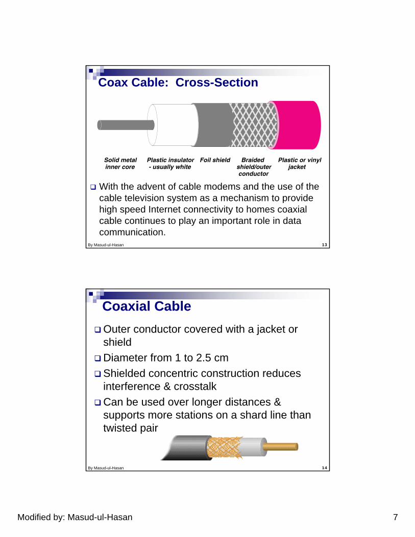
Coax Cable: Cross-Section
Braided shield/outer conductor
Plastic or vinyl jacket
Foil shieldPlastic insulator - usually white
Solid metal inner core
With the advent of cable modems and the use of the cable television system as a mechanism to provide high speed Internet connectivity to homes coaxial cable continues to play an important role in data communication.
By Masud-ul-Hasan 14
Coaxial CableOuter conductor covered with a jacket or shieldDiameter from 1 to 2.5 cmShielded concentric construction reduces interference & crosstalkCan be used over longer distances & supports more stations on a shard line than twisted pair
Modified by: Masud-ul-Hasan 8
By Masud-ul-Hasan 15
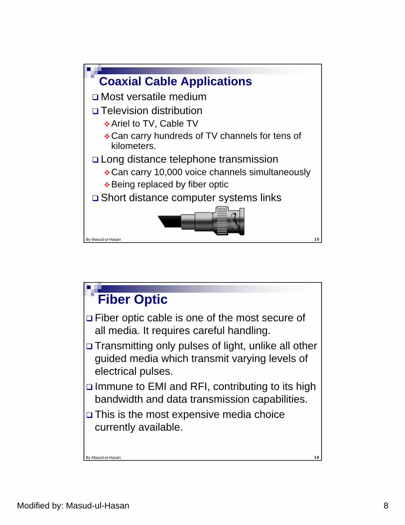
Coaxial Cable ApplicationsMost versatile mediumTelevision distribution
Ariel to TV, Cable TVCan carry hundreds of TV channels for tens of kilometers.
Long distance telephone transmissionCan carry 10,000 voice channels simultaneouslyBeing replaced by fiber optic
Short distance computer systems links
By Masud-ul-Hasan 16
Fiber OpticFiber optic cable is one of the most secure of all media. It requires careful handling.Transmitting only pulses of light, unlike all other guided media which transmit varying levels of electrical pulses.Immune to EMI and RFI, contributing to its high bandwidth and data transmission capabilities.This is the most expensive media choice currently available.
Modified by: Masud-ul-Hasan 9
By Masud-ul-Hasan 17
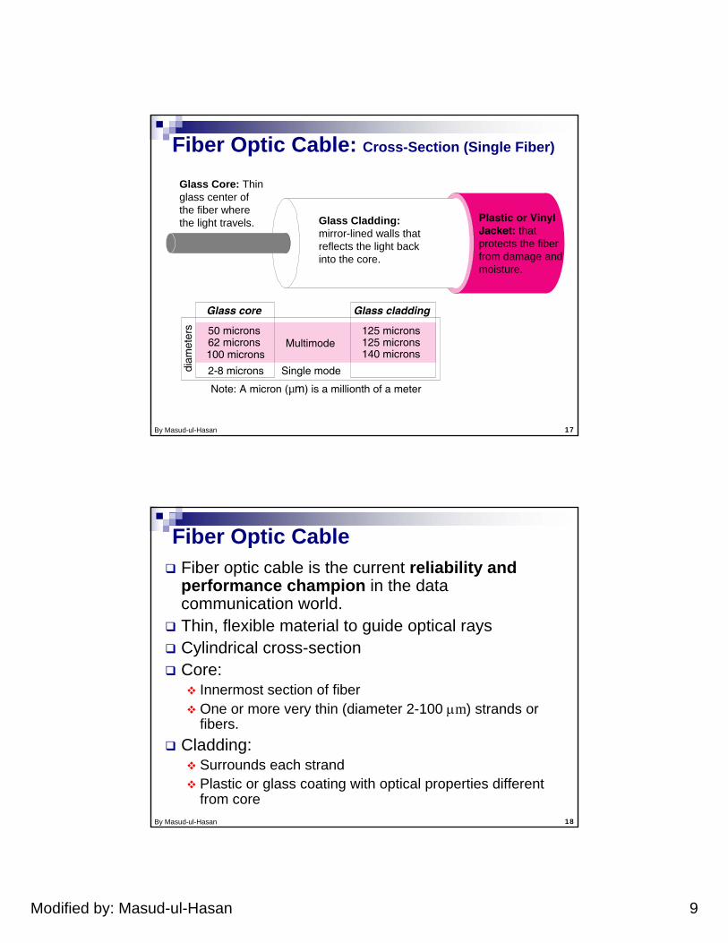
Fiber Optic Cable: Cross-Section (Single Fiber)
Glass core Glass cladding
2-8 microns Single mode
Note: A micron (µm) is a millionth of a meter
125 microns 125 microns 140 microns
Multimode50 microns 62 microns 100 microns
diam
eter
s
Glass Cladding:mirror-lined walls that reflects the light back into the core.
Glass Core: Thin glass center of the fiber where the light travels. Plastic or Vinyl
Jacket: that protects the fiber from damage and moisture.
By Masud-ul-Hasan 18
Fiber optic cable is the current reliability and performance champion in the data communication world.Thin, flexible material to guide optical raysCylindrical cross-section Core:
Innermost section of fiberOne or more very thin (diameter 2-100 µm) strands or fibers.
Cladding:Surrounds each strandPlastic or glass coating with optical properties different from core
Fiber Optic Cable
Modified by: Masud-ul-Hasan 10
By Masud-ul-Hasan 19
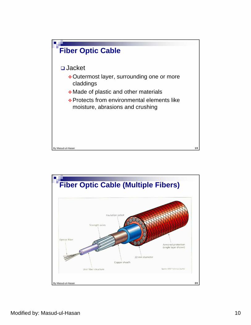
JacketOutermost layer, surrounding one or more claddingsMade of plastic and other materialsProtects from environmental elements like moisture, abrasions and crushing
Fiber Optic Cable
By Masud-ul-Hasan 20
Fiber Optic Cable (Multiple Fibers)
Modified by: Masud-ul-Hasan 11
By Masud-ul-Hasan 21
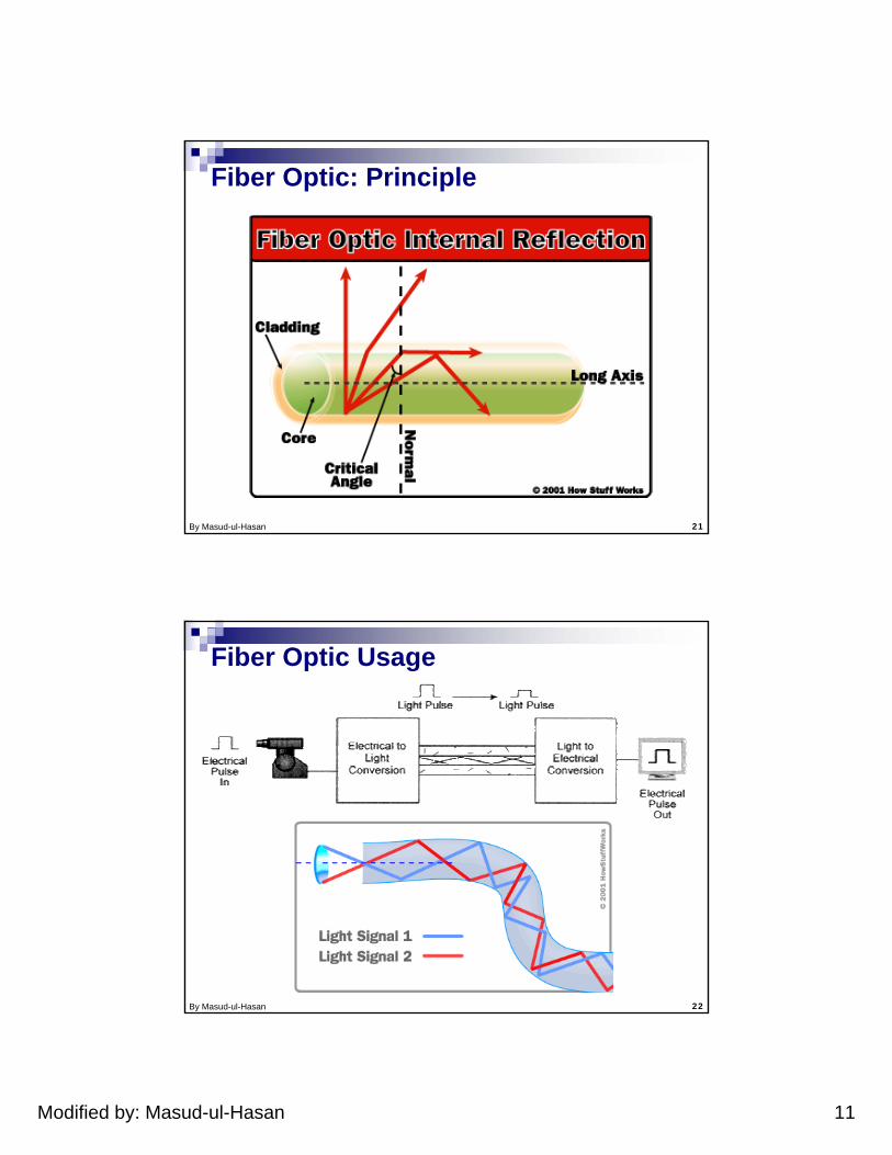
Fiber Optic: Principle
By Masud-ul-Hasan 22
Fiber Optic Usage
Modified by: Masud-ul-Hasan 12
By Masud-ul-Hasan 23
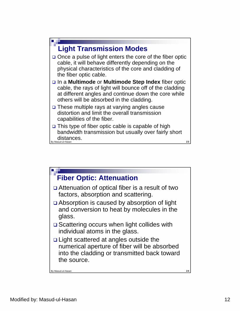
Light Transmission ModesOnce a pulse of light enters the core of the fiber optic cable, it will behave differently depending on the physical characteristics of the core and cladding of the fiber optic cable. In a Multimode or Multimode Step Index fiber optic cable, the rays of light will bounce off of the cladding at different angles and continue down the core while others will be absorbed in the cladding. These multiple rays at varying angles cause distortion and limit the overall transmission capabilities of the fiber. This type of fiber optic cable is capable of high bandwidth transmission but usually over fairly short distances.
By Masud-ul-Hasan 24
Fiber Optic: AttenuationAttenuation of optical fiber is a result of two factors, absorption and scattering.Absorption is caused by absorption of light and conversion to heat by molecules in the glass.Scattering occurs when light collides with individual atoms in the glass.Light scattered at angles outside the numerical aperture of fiber will be absorbed into the cladding or transmitted back toward the source.
Modified by: Masud-ul-Hasan 13
By Masud-ul-Hasan 25
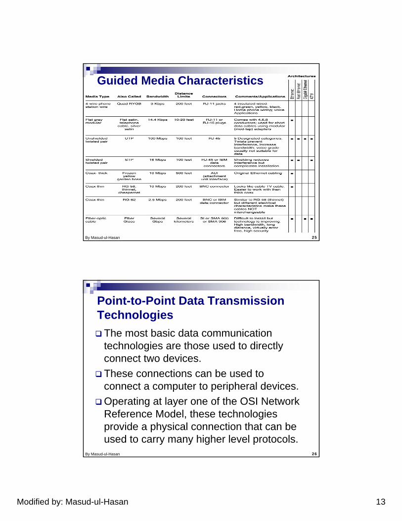
Guided Media Characteristics
By Masud-ul-Hasan 26
Point-to-Point Data Transmission Technologies
The most basic data communication technologies are those used to directly connect two devices. These connections can be used to connect a computer to peripheral devices. Operating at layer one of the OSI Network Reference Model, these technologies provide a physical connection that can be used to carry many higher level protocols.
Modified by: Masud-ul-Hasan 14
By Masud-ul-Hasan 27
Serial Transmission Standards
Serial transmission is the basis of most data communication between computers. There are several different serial communication standards available for use in modern computers including RS-232, USB, and IEEE 1394 (Firewire).
By Masud-ul-Hasan 28
NextPoint-to-Point Data Transmission Technologies
RS232
USB
Firewire (IEEE1394)
Infra Red (IR)
Bluetooth
Modified by: Masud-ul-Hasan 15
By Masud-ul-Hasan 29
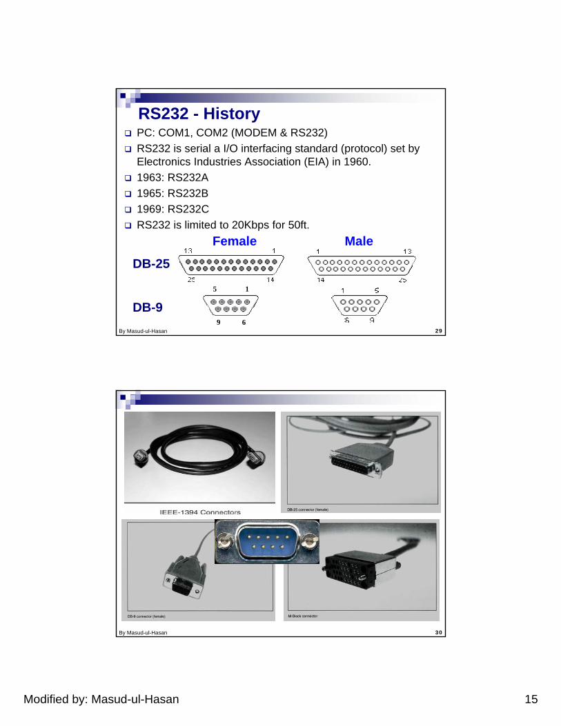
RS232 - HistoryPC: COM1, COM2 (MODEM & RS232)RS232 is serial a I/O interfacing standard (protocol) set by Electronics Industries Association (EIA) in 1960.1963: RS232A1965: RS232B1969: RS232CRS232 is limited to 20Kbps for 50ft.
Female Male
DB-25
DB-915
69
By Masud-ul-Hasan 30
Modified by: Masud-ul-Hasan 16
By Masud-ul-Hasan 31
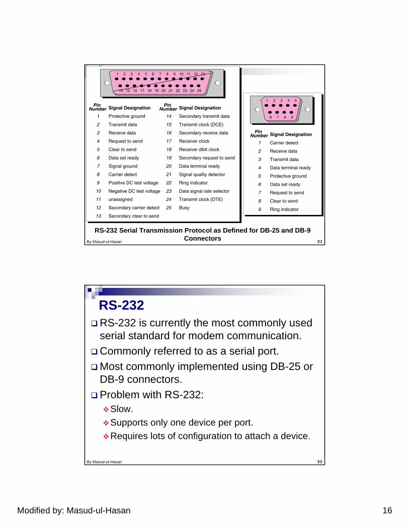
RS-232 Serial Transmission Protocol as Defined for DB-25 and DB-9 Connectors
Protective ground
1 2 3 4 5 6 7 8 9 10 11 12 13
14 15 16 17 18 19 20 21 22 23 24 25
1 2 3 4 5
6 7 8 9
Pin Number Signal Designation Pin
Number Signal Designation
Transmit data
Receive data
Request to send
Clear to send
Data set ready
Signal ground
Carrier detect
Positive DC test voltage
Negative DC test voltage
unassigned
Secondary carrier detect
Secondary clear to send
1
2
3
4
5
6
7
8
9
10
11
12
13
Secondary transmit data
Transmit clock (DCE)
Secondary receive data
Receiver clock
Receiver dibit clock
Secondary request to send
Data terminal ready
Signal quality detector
Ring indicator
Data signal rate selector
Transmit clock (DTE)
Busy
14
15
16
17
18
19
20
21
22
23
24
25
Carrier detect
Pin Number Signal Designation
Receive data
Transmit data
Data terminal ready
Protective ground
Data set ready
Request to send
Clear to send
Ring indicator
1
2
3
4
5
6
7
8
9
By Masud-ul-Hasan 32
RS-232RS-232 is currently the most commonly used serial standard for modem communication. Commonly referred to as a serial port.Most commonly implemented using DB-25 or DB-9 connectors.Problem with RS-232:
Slow.Supports only one device per port.Requires lots of configuration to attach a device.
Modified by: Masud-ul-Hasan 17
By Masud-ul-Hasan 33
Universal Serial Bus (USB)
USB has replaced RS-232 in most of the applications. a high speed, multi-point serial communications technology developed to resolve these shortcomings of RS-232. There are two versions of USB currently available: the original USB 1.1 specification and a newer higher speed USB 2.0 specification. USB 2.0 is backward compatible with USB 1.1
By Masud-ul-Hasan 34
Universal Serial Bus - USB2 data ratesUSB 1.1:
12 Mbps for increased bandwidth devices.1.5 Mbps for lower-speed devices (joysticks, game pads).
USB 2.0:480 Mbps
Star topology can be usedOne USB device (or hub) can be connected to PC. Hub can be embedded in devices like monitor, printer, or keyboard or can be standalone.Multiple USB devices can be connected to hub. Up to 127 devices can be connected in this manner.
Modified by: Masud-ul-Hasan 18
By Masud-ul-Hasan 35
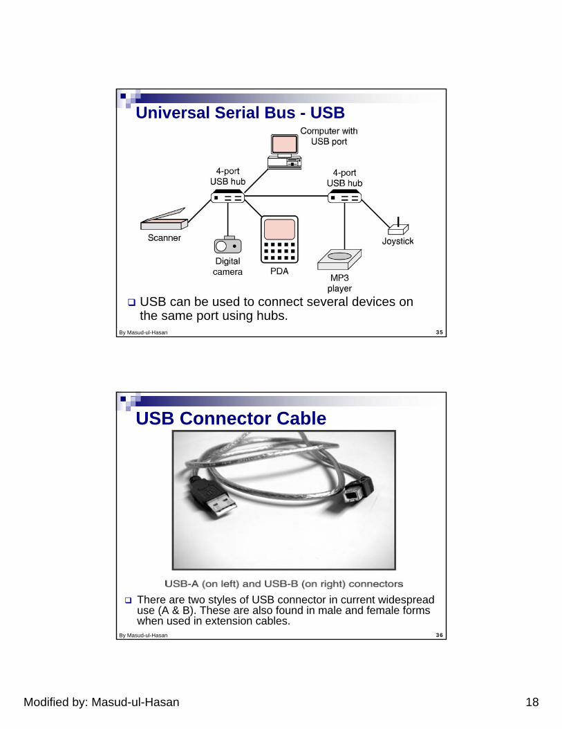
USB can be used to connect several devices on the same port using hubs.
Universal Serial Bus - USB
By Masud-ul-Hasan 36
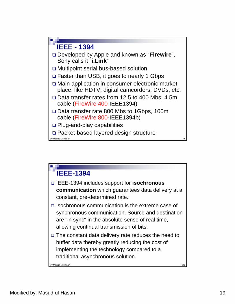
USB Connector Cable
There are two styles of USB connector in current widespread use (A & B). These are also found in male and female forms when used in extension cables.
Modified by: Masud-ul-Hasan 19
By Masud-ul-Hasan 37
IEEE - 1394Developed by Apple and known as “Firewire”, Sony calls it “i.Link”Multipoint serial bus-based solutionFaster than USB, it goes to nearly 1 GbpsMain application in consumer electronic market place, like HDTV, digital camcorders, DVDs, etc.Data transfer rates from 12.5 to 400 Mbs, 4.5m cable (FireWire 400-IEEE1394)Data transfer rate 800 Mbs to 1Gbps, 100m cable (FireWire 800-IEEE1394b)Plug-and-play capabilitiesPacket-based layered design structure
By Masud-ul-Hasan 38
IEEE-1394IEEE-1394 includes support for isochronous communication which guarantees data delivery at a constant, pre-determined rate.Isochronous communication is the extreme case of synchronous communication. Source and destination are "in sync" in the absolute sense of real time, allowing continual transmission of bits. The constant data delivery rate reduces the need to buffer data thereby greatly reducing the cost of implementing the technology compared to a traditional asynchronous solution.
Modified by: Masud-ul-Hasan 20
By Masud-ul-Hasan 39
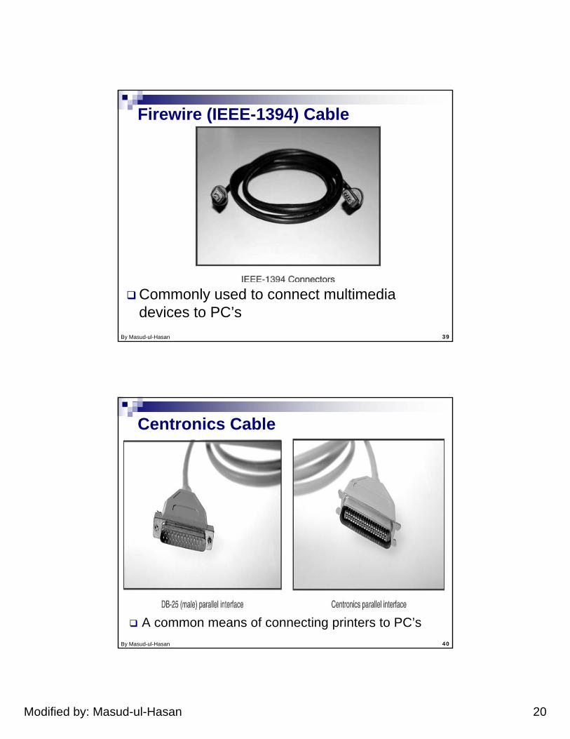
Firewire (IEEE-1394) Cable
Commonly used to connect multimedia devices to PC’s
By Masud-ul-Hasan 40
Centronics Cable
A common means of connecting printers to PC’s
Modified by: Masud-ul-Hasan 21
By Masud-ul-Hasan 41
Wireless communicationInfrared (IR)
Uses electronic wave frequencies just below visible light spectrumDiode emits infrared light to generate signalInfrared transistor detects signal, conducts when exposed to infrared lightCheap to build transmitter and receiver circuitsNeed line of sight, limited range
Radio frequency (RF)Uses electromagnetic wave frequencies in radio spectrumAnalog circuitry and antenna needed on both sides of transmissionLine of sight not needed, transmitter power determines range
By Masud-ul-Hasan 42
Wireless protocols: IrDAIrDA (Infrared Data Association)
Created and promoted by the Infrared Data Association (IrDA).Supports short-range point-to-point infrared data transmission (around 1 meter), have a narrow angle (30 degree cone).Data transfer rate - between 9.6 kbps and 4 Mbps.IrDA hardware deployed in notebook computers, printers, PDAs, digital cameras, public phones, cell phones (small, semi-transparent, red window in laptops).Lack of suitable drivers has slowed use by applications.
Modified by: Masud-ul-Hasan 22
By Masud-ul-Hasan 43
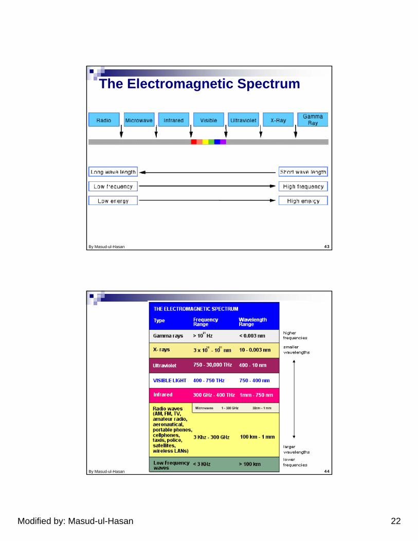
The Electromagnetic Spectrum
By Masud-ul-Hasan 44
Modified by: Masud-ul-Hasan 23
By Masud-ul-Hasan 45
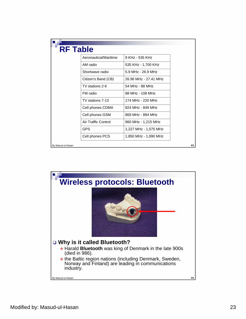
RF Table
1,850 MHz - 1,990 MHzCell phones PCS
1,227 MHz - 1,575 MHzGPS
960 MHz - 1,215 MHzAir Traffic Control
869 MHz - 894 MHzCell phones GSM
824 MHz - 849 MHzCell phones CDMA
174 MHz - 220 MHzTV stations 7-13
88 MHz - 108 MHzFM radio
54 MHz - 88 MHzTV stations 2-6
26.96 MHz - 27.41 MHzCitizen's Band (CB)
5.9 MHz - 26.9 MHzShortwave radio
535 KHz - 1,700 KHzAM radio
9 KHz - 535 KHzAeronautical/Maritime
By Masud-ul-Hasan 46
Wireless protocols: Bluetooth
Why is it called Bluetooth?Harald Bluetooth was king of Denmark in the late 900s (died in 986).the Baltic region nations (including Denmark, Sweden, Norway and Finland) are leading in communications industry.
Modified by: Masud-ul-Hasan 24
By Masud-ul-Hasan 47
BluetoothNew global standard for wireless connectivityBased on low-cost, short-range radio linkConnection established when within 10 meters of each otherNo line-of-sight required
e.g., Laptop connects to a printer in another roomBluetooth communicates at a frequency of 2.45 gigahertz, which has been set aside by international agreement for the use of Industrial, Scientific and Medical devices (ISM).
By Masud-ul-Hasan 48
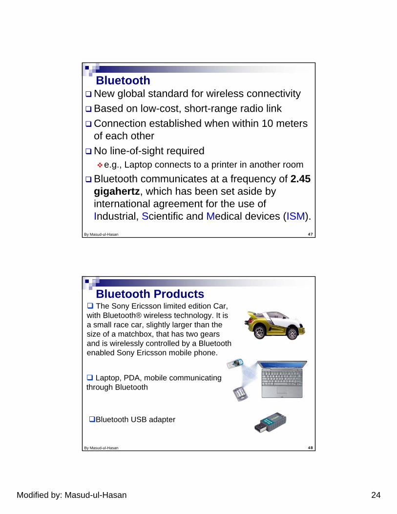
Bluetooth ProductsThe Sony Ericsson limited edition Car,
with Bluetooth® wireless technology. It is a small race car, slightly larger than the size of a matchbox, that has two gears and is wirelessly controlled by a Bluetooth enabled Sony Ericsson mobile phone.
Laptop, PDA, mobile communicating through Bluetooth
Bluetooth USB adapter
Modified by: Masud-ul-Hasan 25
By Masud-ul-Hasan 49
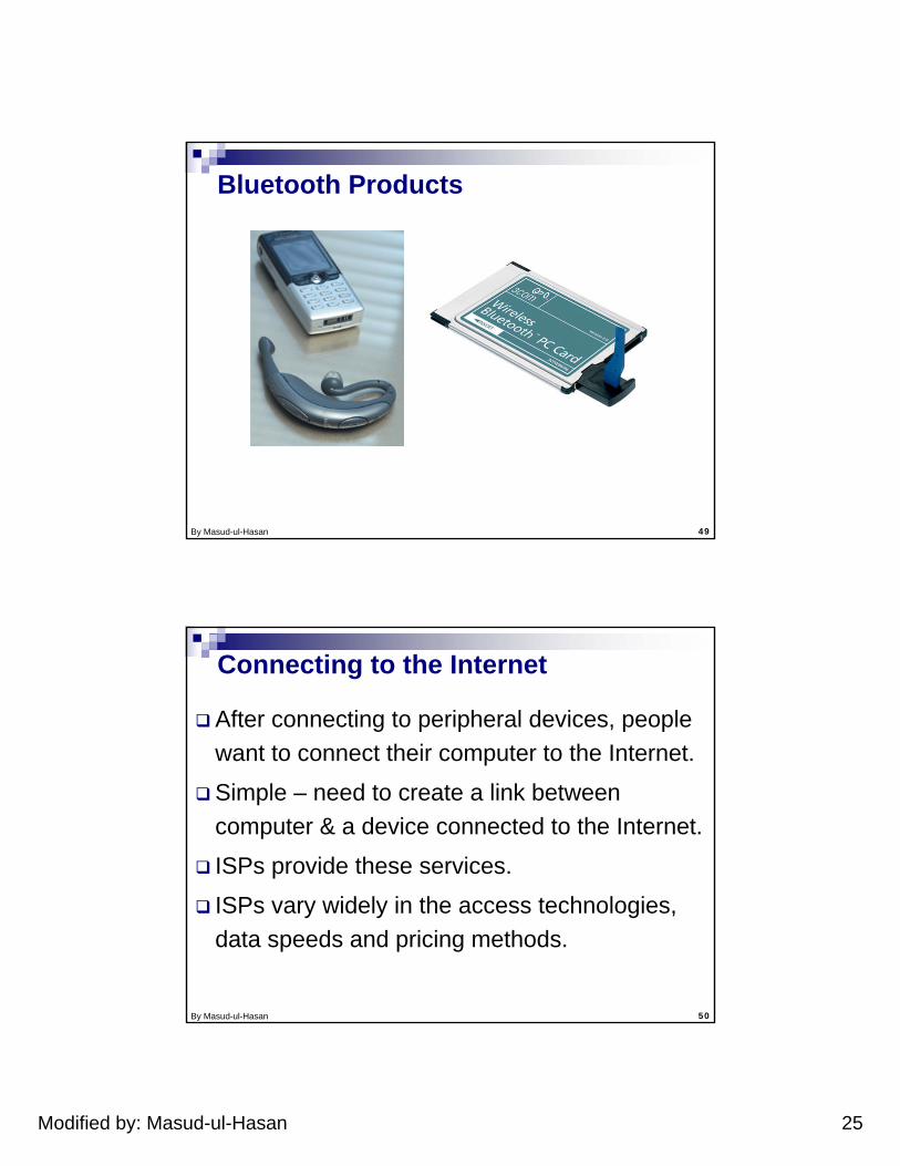
Bluetooth Products
By Masud-ul-Hasan 50
Connecting to the Internet
After connecting to peripheral devices, people want to connect their computer to the Internet.
Simple – need to create a link between computer & a device connected to the Internet.
ISPs provide these services.
ISPs vary widely in the access technologies, data speeds and pricing methods.
Modified by: Masud-ul-Hasan 26
By Masud-ul-Hasan 51
Connecting to the InternetAll ISPs provide access to same Internet, so it is important to look at the four key criteria:
Service hosting: Need of ISP to host Web pages, domain names, e-mail addresses, etc.
Performance: Type of access technologies supported, data rates, throughput, etc.
Cost: Hourly/Monthly rates, rates per Mb, etc.
Reliability: ISPs multiple links to Internet, multiple links to the customer, etc.
By Masud-ul-Hasan 52
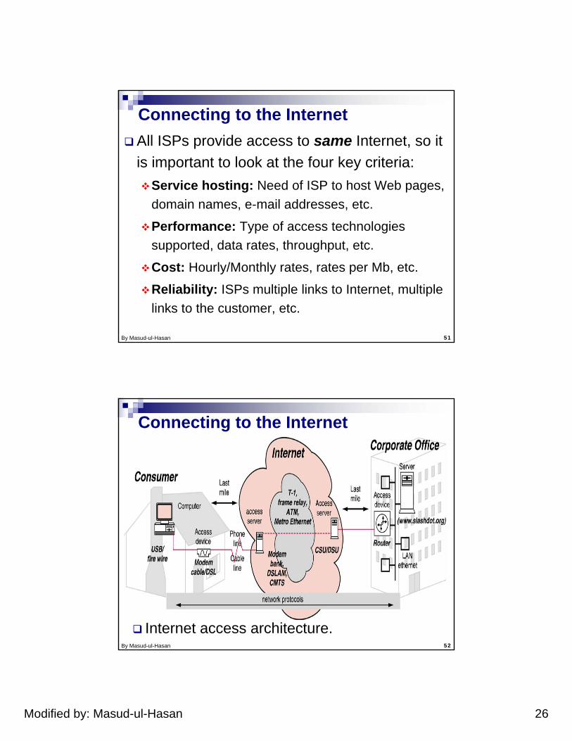
Connecting to the Internet
Internet access architecture.
Modified by: Masud-ul-Hasan 27
By Masud-ul-Hasan 53
Public Switched Telephone Network (PSTN)
The public dial-up network is accessed using a dial-up modem.
By Masud-ul-Hasan 54
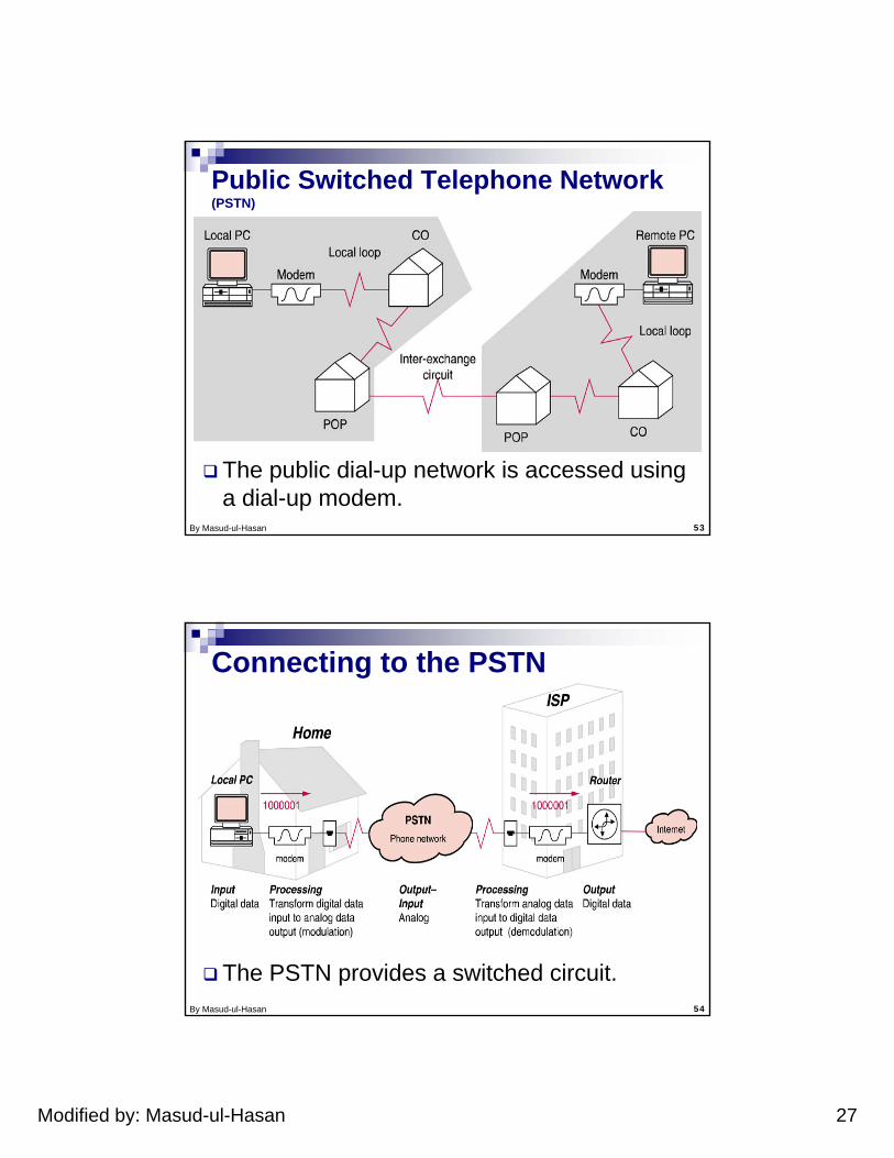
Connecting to the PSTN
The PSTN provides a switched circuit.
Modified by: Masud-ul-Hasan 28
By Masud-ul-Hasan 55
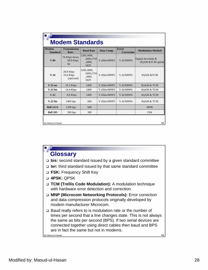
Modem Standards
FSK300300 bpsBell 103
4PSK6001200 bpsBell 212A
4QAM & TCMV.42/MNP4V.42bis/MNP56002400 bpsV.22 bis
4QAM & TCMV.42/MNP4V.42bis/MNP524009.6 KbpsV.32
6QAM & TCMV.42/MNP4V.42bis/MNP5240014.4 KbpsV.32 bis8QAM & TCMV.42/MNP4V.42bis/MNP5240019.2 KbpsV.32 ter
9QAM &TCMV.42/MNP4V.42bis/MNP5
3200,3000,2400,2743,2800,3429
28.8 Kbps33.6 Kbps
(optional)V.34
Digital downlink & 9QAM &TCM uplinkV.42/MNP4V.42bis/MNP5
3200,3000,2400,2743,2800,3429
56 Kbps down, 28.8 Kbps up
V.90
Modulation MethodError CorrectionData Comp.Baud RateTransmission
RateModem
Standard
By Masud-ul-Hasan 56
Glossarybis: second standard issued by a given standard committeeter: third standard issued by that same standard committeeFSK: Frequency Shift Key4PSK: QPSKTCM (Trellis Code Modulation): A modulation technique with hardware error detection and correction.MNP (Microcom Networking Protocols): Error correction and data compression protocols originally developed by modem manufacturer Microcom. Baud really refers to is modulation rate or the number of times per second that a line changes state. This is not always the same as bits per second (BPS). If two serial devices are connected together using direct cables then baud and BPS are in fact the same but not in modems.
Modified by: Masud-ul-Hasan 29
By Masud-ul-Hasan 57
Modems and the PSTN Modem is actually a contraction for Modulator/demodulator. Most local loops that are used for connection to the PSTN to supply switched, dial-up phone service are physically described as two-wire circuits. Since one of these two wires serves as a ground wire for the circuit, that leaves only one wire between the two ends of the circuit for data signaling. Dial-up or switched two-wire circuits generate a dial-tone.
By Masud-ul-Hasan 58
Full-duplexFull-duplex transmission supports simultaneous data signaling in both directions. Full-duplex transmission might seem to be impossible on two-wire circuits. Modems manufactured to the CCITT's V.32 standard (and the later V.34 standard) can transmit in full-duplex mode, thereby receiving and transmitting simultaneously over dial-up two-wire circuits.
Modified by: Masud-ul-Hasan 30
By Masud-ul-Hasan 59
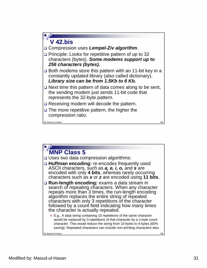
Quantization Noise Conversion of an analog signal to digital format imparts “noise” into the signal. Why?Analog signals can consist of any possible level.Digital signals consist of only fixed levels. When analog signal is sampled and converted into a digital signal, certain level of detail is lost.When digital signal is converted back into analog, it will not be exactly same. This error is known as “Quantization Noise”.V.90 modem standard overcome this problem.
By Masud-ul-Hasan 60
Original Analog Waveform
Digital Sampling Recreated Analog Waveform
quantization noise
digital data stream
..0010011000100011..
Quantization Noise
Modified by: Masud-ul-Hasan 31
By Masud-ul-Hasan 61
V 42.bisCompression uses Lempel-Ziv algorithm.Principle: Looks for repetitive pattern of up to 32 characters (bytes). Some modems support up to 256 characters (bytes).Both modems store this pattern with an 11-bit key in a constantly updated library (also called dictionary). Library size can be from 1.5Kb to 6 Kb.Next time this pattern of data comes along to be sent, the sending modem just sends 11-bit code that represents the 32-byte pattern.Receiving modem will decode the pattern.The more repetitive pattern, the higher the compression ratio.
By Masud-ul-Hasan 62
MNP Class 5Uses two data compression algorithms:Huffman encoding: re-encodes frequently used ASCII characters, such as a, e, i, o, and s are encoded with only 4 bits, whereas rarely occurring characters such as x or z are encoded using 11 bits.Run-length encoding: exams a data stream in search of repeating characters. When any character repeats more than 3 times, the run-length encoding algorithm replaces the entire string of repeated characters with only 3 repetitions of the character followed by a count field indicating how many times the character is actually repeated.
E.g., A data string containing 10 repetitions of the same character would be replaced by 3 repetitions of that character by a 1-byte count character. This would reduce the string from 10 bytes to 4-bytes (60% saving). Repeated characters can include non-printing characters also.
Modified by: Masud-ul-Hasan 32
By Masud-ul-Hasan 63
ReliabilityGoal of reliable transmission is to minimize the error rate.Improved reliability implies faster data transmission. Fewer retransmission increase the throughput.First category of error correction technique is to prevent errors from happening by optimizing the condition of the transmission link.Second category-if errors occur, then detectand correct the errors.
By Masud-ul-Hasan 64
Error Prevention
Errors occur when data is misinterpreted due to noise or interference on transmission lines.Errors can be prevented by:
Reducing the amount of noise or interference on a given transmission line.Employing modulation techniques that are able to adapt to and overcome noisy lines.
Modified by: Masud-ul-Hasan 33
By Masud-ul-Hasan 65
Line ConditioningValue added service provided by phone companies. Line conditioning is available for analog leased circuits. It helps eliminate noise and interference.Additional equipment is installed to guarantee signal quality.Signals tend to lose their strength over great distances due to the resistance of the wire, this is known as attenuation. Repeaters and amplifiers help assure signal quality over longer distances.
By Masud-ul-Hasan 66
Repeaters and AmplifiersA repeater is used to overcome attenuation.A repeater regenerates the digital signal.A repeater on an analog circuit is called an amplifier.An amplifier does not distinguish between voice data signal and the background noise. So amplifies both.Repeaters on digital circuits are able to distinguish. So retransmit a digital signal free of noise.The use of digital leased lines could itself be seen as an error prevention technique.
Modified by: Masud-ul-Hasan 34
By Masud-ul-Hasan 67
Adaptive ProtocolsAdapt (adjust) transmission session parameters in response to various line conditions.Techniques play on one of two things:
Amount of data per packet (adaptive size packet assembly).Transmission rate is varied according to line conditions (dynamic speed shifts).
By Masud-ul-Hasan 68
Adaptive Size Packet AssemblyMNP class 4 protocol.Increase and decrease amount of data per packet based on circuit condition.Protocol optimizes amount of data per packet by building packets containing the greatest amount of data that can be transmitted reliably without requiring retransmission.When errors are detected, packet size is reduced. When no errors are detected over time, packet sizes are increased.
Modified by: Masud-ul-Hasan 35
By Masud-ul-Hasan 69
Dynamic Speed ShiftsMNP class 10 adaptive protocol.Allows two modems changing their speed up or down during the transmission session in response to varying line conditions.The adaptive nature of this protocol ensures that the highest practical transmission speed will be used at all times.Useful in cellular phone environments where line quality varies significantly over short periods of time.
By Masud-ul-Hasan 70
Forward Error CorrectionCorrection of the received data without the need for retransmission.A communications technique that can correct bad data on the receiving end. Before transmission, the data are processed through an algorithm that adds extra (redundant) bits for error correction.If the redundant bits calculated at the receiver do not match the received ones, the forward error correction circuitry at the receiver uses those bits to correct the incoming data signal.
Modified by: Masud-ul-Hasan 36
By Masud-ul-Hasan 71
Forward Error Correction
Cost More redundant data is added to the transmitted blocks.Hence Reduction in data throughputCompromise:
Not enough redundant data, the overall throughput is reduced due to retransmissions.Too much redundant data will also reduce the throughput due to time spent to send data and processing at the receiver.
By Masud-ul-Hasan 72
Trellis Coded Modulation (TCM)
Another way of overcoming errors without the need for retransmission.Modems that employ TCM can overcome twice as much noise on a given circuit as QAM modems without TCM.Uses technique called convolutional encoding.TCM adds a redundant bit to avoid misinterpreting the received sequence.
Modified by: Masud-ul-Hasan 37
By Masud-ul-Hasan 73
Error Control StandardsMNP 4
Adaptive size packet assemblyV.42:
Incorporates MNP 4 and the Link Access Protocol for Modems (LAP-M).LAP-M uses selective ARQ.Provides for negotiation during modem handshaking to allow modems to decide which protocol to use whether MNP 4 or LAP-M.V.42 is not to be confused with CCITT V.42bis used for data compression.
By Masud-ul-Hasan 74
MNP4 and V.42
Error control protocols implemented within modems.Modems assure error-free transmissions.Error control protocol, supplied by communications software running on PC’s, is not needed.
Modified by: Masud-ul-Hasan 38
By Masud-ul-Hasan 75
Hardware Flow Control (RTS/CTS)Involves the use of additional pins on the interface to start or stop the flow of data.RS-232 uses pins 4 & 5 for RTS (request to send) & CTS (clear to send):
CTS pin high Transmitter sends data into buffer memoryCTS pin low Transmitter stops transmitting data
By Masud-ul-Hasan 76
Software Flow Control (XON/XOFF)Instead of using pins 4 & 5Sends special characters in the data.The most popular flow control standard is known as XON/XOFF.
When a device cannot receive data it sends a XOFF (Ctrl-S).To resume transfer of data receiving device sends an XON character (Ctrl-Q).
Modified by: Masud-ul-Hasan 39
By Masud-ul-Hasan 77
Digital Subscriber Line (DSL)
One of the faster broadband technologies currently available is Digital Subscriber Line (DSL). DSL provides an “always on” connection to the Internet over the same copper wires that provide dial-up telephone service. DSL uses the same copper wire (local loop) as a POTS (Plain Old Telephone Service) line, but digital because of equipment used on both ends (user and CO).
By Masud-ul-Hasan 78
DSL Standards and Technology
Not like dial-up modems, there is less standardization in the DSL world. Different vendors have developed different solutions that use different frequencies and modulation schemes. The only two devices that have to agree on the DSL technology used are the DSL modem and the DSLAM (DSL Access Multiplexer). Most DSL service providers require customers to rent or purchase DSL modems directly from them.
Modified by: Masud-ul-Hasan 40
By Masud-ul-Hasan 79
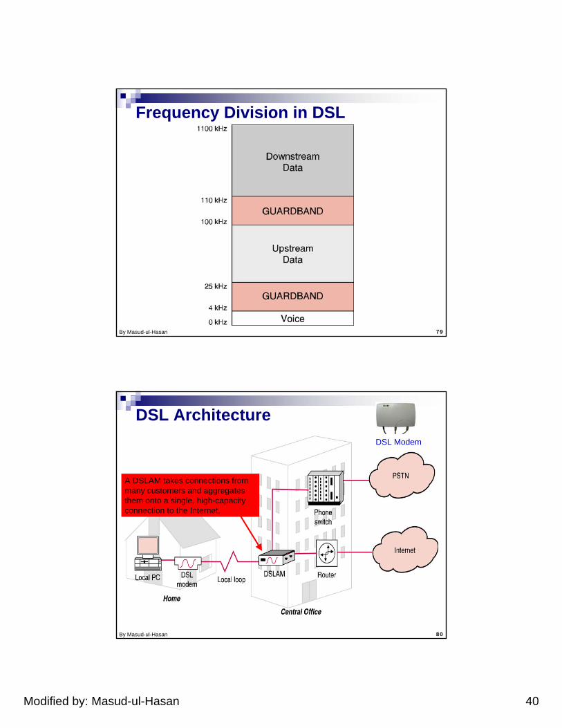
Frequency Division in DSL
By Masud-ul-Hasan 80
DSL Architecture
A DSLAM takes connections from many customers and aggregates them onto a single, high-capacity connection to the Internet.
DSL Modem
Modified by: Masud-ul-Hasan 41
By Masud-ul-Hasan 81
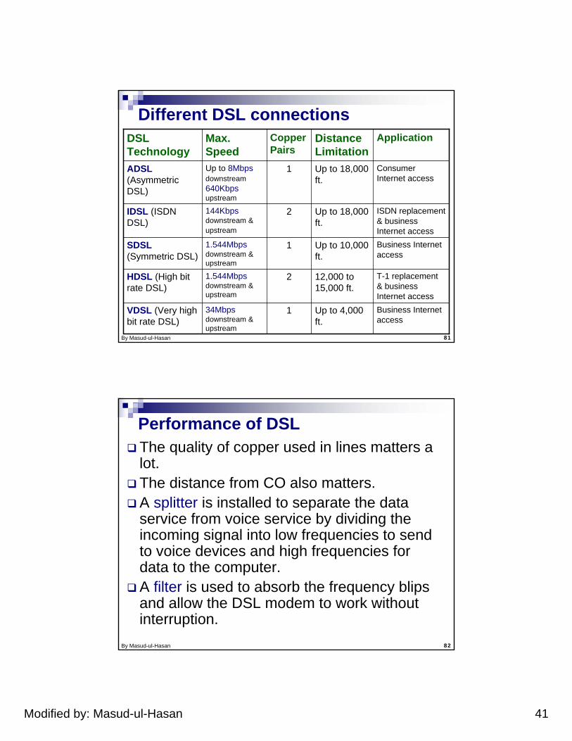
Different DSL connections
34Mbps downstream & upstream
1.544Mbps downstream & upstream
1.544Mbps downstream & upstream
144Kbps downstream & upstream
Up to 8Mbpsdownstream640Kbpsupstream
Max. Speed
1
2
1
2
1
Copper Pairs
ISDN replacement & business Internet access
Up to 18,000 ft.
IDSL (ISDN DSL)
Business Internet access
Up to 10,000 ft.
SDSL (Symmetric DSL)
Business Internet access
Up to 4,000 ft.
VDSL (Very high bit rate DSL)
T-1 replacement & business Internet access
12,000 to 15,000 ft.
HDSL (High bit rate DSL)
Consumer Internet access
Up to 18,000 ft.
ADSL (Asymmetric DSL)
ApplicationDistance Limitation
DSL Technology
By Masud-ul-Hasan 82
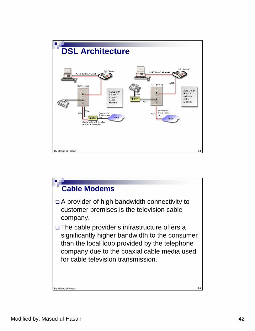
Performance of DSLThe quality of copper used in lines matters a lot.The distance from CO also matters.A splitter is installed to separate the data service from voice service by dividing the incoming signal into low frequencies to send to voice devices and high frequencies for data to the computer. A filter is used to absorb the frequency blips and allow the DSL modem to work without interruption.
Modified by: Masud-ul-Hasan 42
By Masud-ul-Hasan 83
DSL Architecture
By Masud-ul-Hasan 84
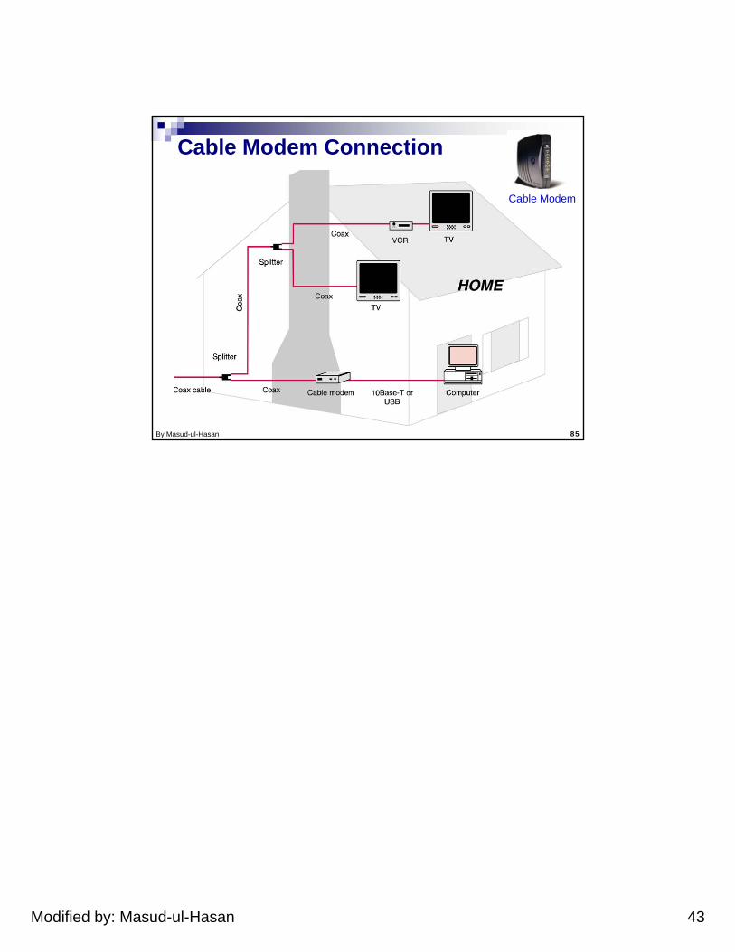
Cable ModemsA provider of high bandwidth connectivity to customer premises is the television cable company. The cable provider’s infrastructure offers a significantly higher bandwidth to the consumer than the local loop provided by the telephone company due to the coaxial cable media used for cable television transmission.
Modified by: Masud-ul-Hasan 43
By Masud-ul-Hasan 85
Cable Modem Connection
Cable Modem