Embed Size (px)
Citation preview

iRIS 350FX Reference Manual V1.00
iRIS 350FX
Basic User Guide For Software Version: 1.50
Requires Firmware Version: Vz/1.50+
2 HyQuest Solutions (NZ) Ltd - PO Box 9466, Hamilton, New Zealand Tel: +64 7 857-0810 Email: [email protected]
Disclaimer Under no circumstances will HyQuest Solutions (NZ) Ltd be liable or responsible for any consequential damage or loss that may arise from the use of this product. All examples and diagrams shown in this manual and any supplied software examples are intended as a guide to understanding this product, not to guarantee operation. HyQuest Solutions (NZ) Ltd accepts no responsibility for use of this product based on this information or these examples. Owing to the wide variety of possible applications of this product, you must satisfy yourself as to its suitability to your specific application. © 2014, HyQuest Solutions (NZ) Ltd All rights reserved. This publication, or any part of it, and any software accompanying it may not be copied, photocopied, reproduced, translated or communicated to any third party, or reduced to electronic medium without prior written permission from HyQuest Solutions (NZ) Ltd.
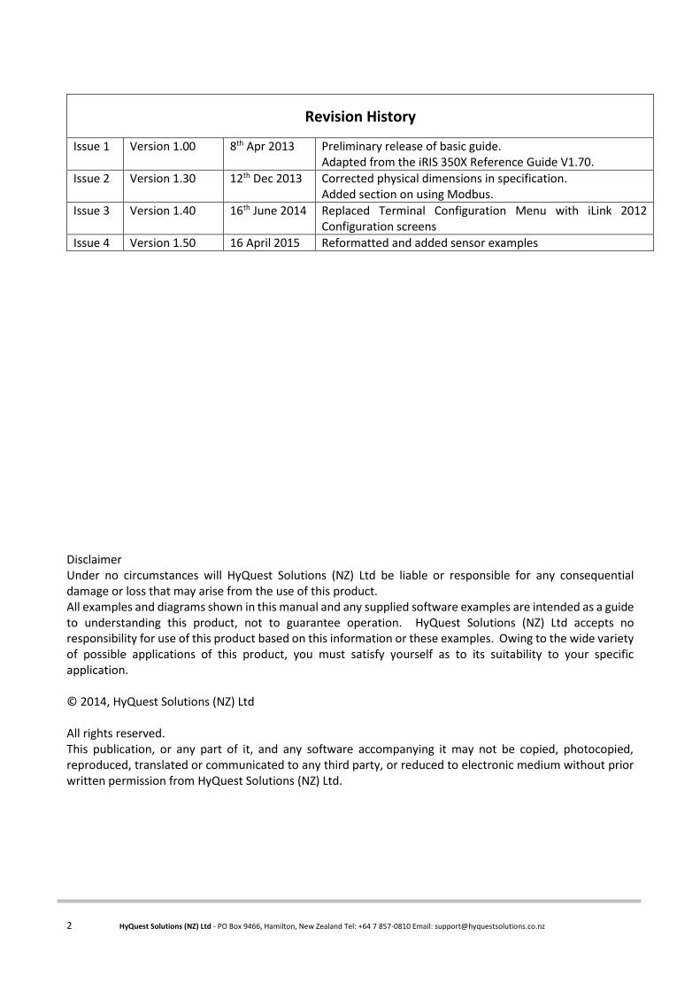
Revision History
Issue 1 Version 1.00 8th Apr 2013 Preliminary release of basic guide. Adapted from the iRIS 350X Reference Guide V1.70.
Issue 2 Version 1.30 12th Dec 2013 Corrected physical dimensions in specification. Added section on using Modbus.
Issue 3 Version 1.40 16th June 2014 Replaced Terminal Configuration Menu with iLink 2012 Configuration screens
Issue 4 Version 1.50 16 April 2015 Reformatted and added sensor examples

iRIS 350FX Reference Manual V1.50
i HyQuest Solutions (NZ) Ltd - PO Box 9466, Hamilton, New Zealand Tel: +64 7 857-0810 Email: [email protected]
Table of Contents
1 Declaration of Conformity ...................................................................................................... 1
2 Introduction ........................................................................................................................... 2
About this Basic User Guide ...................................................................................................... 2
1.1 Support ...................................................................................................................................... 2
3 Overview ............................................................................................................................... 3
Introduction .............................................................................................................................. 3
Features .................................................................................................................................... 3
Typical Applications .................................................................................................................. 3
Key Features .............................................................................................................................. 4
Terminal Diagnostics .......................................................................................................... 4
Wireless IP Connectivity .................................................................................................... 4
Alternative Wireless Connectivity (SMS or FTP) ................................................................ 4
Power Management .......................................................................................................... 4
Data Logging ...................................................................................................................... 5
Logged Data Array Identification ....................................................................................... 6
Alarm Processing ............................................................................................................... 6
Real Time Clock & Calendar ............................................................................................... 6
Security .............................................................................................................................. 7
Gateway Communication .................................................................................................. 7
4 iRIS 350X and iRIS 350FX Comparison ...................................................................................... 8
5 Installation ............................................................................................................................. 9
Opening / Closing the Housing .................................................................................................. 9
Removing / fitting the SIM card ................................................................................................ 9
I/O Connector............................................................................................................................ 9
Internal Battery ................................................................................................................ 10
Internal/External 12V Battery Supply .............................................................................. 11
External (Charger) Power Supply ..................................................................................... 11
Analogue I/O .................................................................................................................... 11
Digital I/O ......................................................................................................................... 12
6 Configuration ....................................................................................................................... 16
Terminal Connection ............................................................................................................... 16
Terminal Security Code ........................................................................................................... 16
Configuration Menus .............................................................................................................. 17
General ............................................................................................................................ 17
Power ............................................................................................................................... 19
Comms ............................................................................................................................. 21
iRIS 350FX Reference Manual V1.50
ii HyQuest Solutions (NZ) Ltd - PO Box 9466, Hamilton, New Zealand Tel: +64 7 857-0810 Email: [email protected]
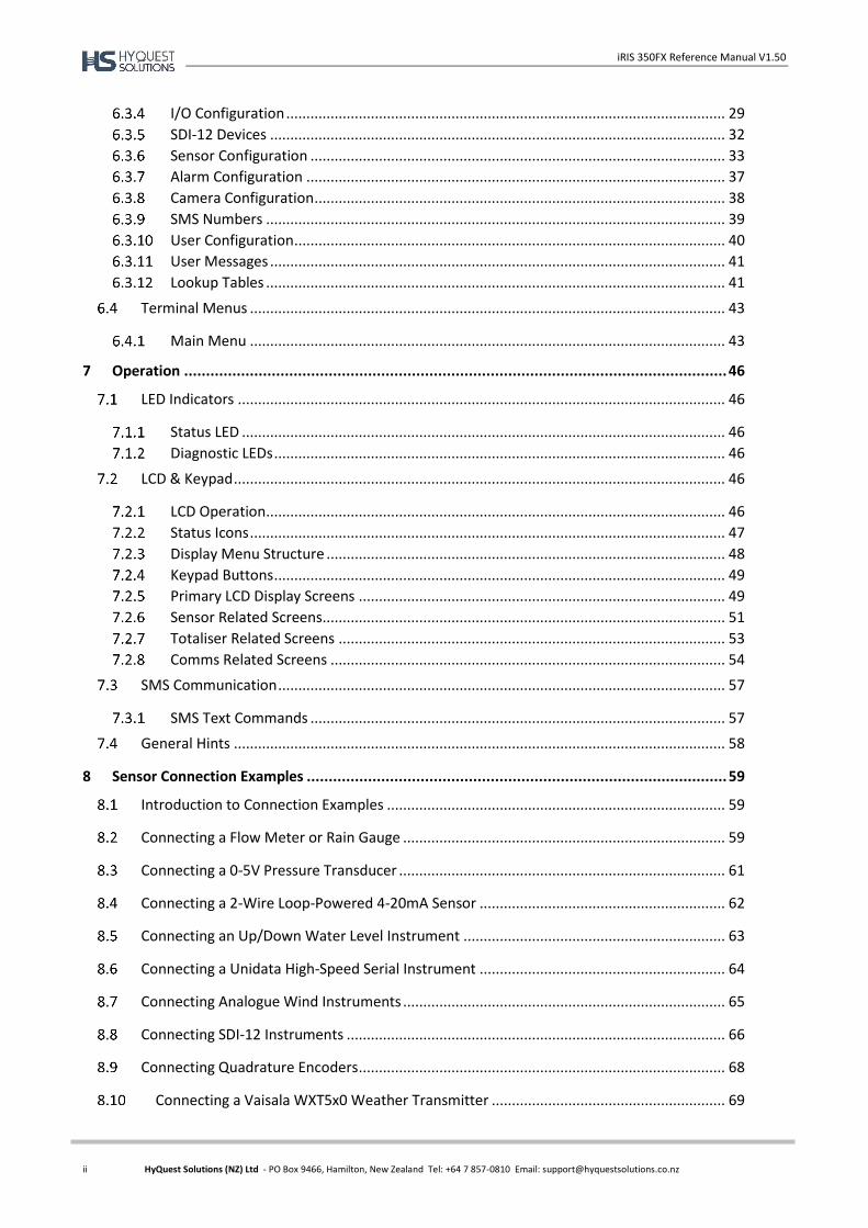
I/O Configuration ............................................................................................................. 29
SDI-12 Devices ................................................................................................................. 32
Sensor Configuration ....................................................................................................... 33
Alarm Configuration ........................................................................................................ 37
Camera Configuration ...................................................................................................... 38
SMS Numbers .................................................................................................................. 39
User Configuration ........................................................................................................... 40
User Messages ................................................................................................................. 41
Lookup Tables .................................................................................................................. 41
Terminal Menus ...................................................................................................................... 43
Main Menu ...................................................................................................................... 43
7 Operation ............................................................................................................................ 46
LED Indicators ......................................................................................................................... 46
Status LED ........................................................................................................................ 46
Diagnostic LEDs ................................................................................................................ 46
LCD & Keypad .......................................................................................................................... 46
LCD Operation .................................................................................................................. 46
Status Icons ...................................................................................................................... 47
Display Menu Structure ................................................................................................... 48
Keypad Buttons ................................................................................................................ 49
Primary LCD Display Screens ........................................................................................... 49
Sensor Related Screens .................................................................................................... 51
Totaliser Related Screens ................................................................................................ 53
Comms Related Screens .................................................................................................. 54
SMS Communication ............................................................................................................... 57
SMS Text Commands ....................................................................................................... 57
General Hints .......................................................................................................................... 58
8 Sensor Connection Examples ................................................................................................ 59
Introduction to Connection Examples .................................................................................... 59
Connecting a Flow Meter or Rain Gauge ................................................................................ 59
Connecting a 0-5V Pressure Transducer ................................................................................. 61
Connecting a 2-Wire Loop-Powered 4-20mA Sensor ............................................................. 62
Connecting an Up/Down Water Level Instrument ................................................................. 63
Connecting a Unidata High-Speed Serial Instrument ............................................................. 64
Connecting Analogue Wind Instruments ................................................................................ 65
Connecting SDI-12 Instruments .............................................................................................. 66
Connecting Quadrature Encoders ........................................................................................... 68
Connecting a Vaisala WXT5x0 Weather Transmitter .......................................................... 69

iRIS 350FX Reference Manual V1.50
iii HyQuest Solutions (NZ) Ltd - PO Box 9466, Hamilton, New Zealand Tel: +64 7 857-0810 Email: [email protected]
Configuration ................................................................................................................... 69
Vaisala Configuration Software Settings ......................................................................... 70
iRIS Sensor Configuration ................................................................................................ 71
9 Analogue Input Scaling ......................................................................................................... 72
Example: A 4-20mA Water Level Sensor ................................................................................. 72
10 RS232 Interface Telemetry / Gateway Comms ....................................................................... 73
Overview .............................................................................................................................. 73
RS232 Port Telemetry .......................................................................................................... 73
RS232 Only Telemetry Mode ........................................................................................... 73
Non-Dedicated RS232 Telemetry Mode .......................................................................... 74
Gateway Communication .................................................................................................... 74
Aliased Gateway explained .............................................................................................. 75
Gateway example ............................................................................................................ 75
11 Using Modbus Slave Mode ................................................................................................... 77
Configuring iRIS 350FX to use Modbus ............................................................................... 77
Enabling RS232 Modbus Operation using Keypad/LCD ...................................................... 79
12 Troubleshooting ................................................................................................................... 80
Can’t connect to the iRIS via the RS232 port. ..................................................................... 80
iRIS will not start when the battery is first connected. ....................................................... 80
Pulse lost when iRIS connected to other equipment. ......................................................... 80
Unable to connect to an IP network. .................................................................................. 80
iRIS will not respond to SMS requests. ................................................................................ 80
iRIS 350FXV answers a voice call, but no sound is heard. ................................................... 80
Unable to access terminal menu. ........................................................................................ 81
Digital Output activates when user is logged on. ................................................................ 81
SDI-12 sensors log a “NaN” value. ....................................................................................... 81
Sensor values not included in SMS reply to “RQ”. .............................................................. 81
External 12V battery not charging as expected. ................................................................. 81
13 Appendix A – Specific Information ........................................................................................ 82
General Characteristics ....................................................................................................... 82
Technical Specifications ....................................................................................................... 83
Antenna Connection ............................................................................................................ 84
Mounting ............................................................................................................................. 85
iRIS 350FX Reference Manual V1.50
iv HyQuest Solutions (NZ) Ltd - PO Box 9466, Hamilton, New Zealand Tel: +64 7 857-0810 Email: [email protected]
14 Appendix B – Voice Annunciation (iRIS 350FXV) .................................................................... 86
Loading Wave Files into the iRIS .......................................................................................... 87
Audio File Settings ........................................................................................................... 88
Audio Script Settings ........................................................................................................ 88
Uploading Audio Files over a Remote Connection .......................................................... 90
15 Appendix C – Using an iRIS-CAM Camera ............................................................................... 90
Overview .............................................................................................................................. 90
Specifications ....................................................................................................................... 90
Mounting ............................................................................................................................. 91
Connecting the iRIS-CAM .................................................................................................... 91
Installing PC Based Software & USB Drivers ........................................................................ 92
Connecting to the PC ........................................................................................................... 93
Focusing ............................................................................................................................... 94
iRIS Configuration ................................................................................................................ 94
Installing iRIS Software for Camera Support ................................................................... 94
Configure the Camera on the iRIS ................................................................................... 94
16 Appendix D – Upgrading Firmware/Software ........................................................................ 95
Overview .............................................................................................................................. 95
File Naming Conventions ..................................................................................................... 95
iRIS Executive Firmware ................................................................................................... 95
iRIS Application Software................................................................................................. 95
Module OpenAT ............................................................................................................... 96
iRIS Automated Upgrade Procedure (Software/Firmware) ................................................ 96
1.2 iRIS Manual Upgrade Procedure (Software/Firmware) .......................................................... 97
17 APPENDIX E – SDI-12 ............................................................................................................ 99
What is SDI-12? ................................................................................................................... 99
Advantages of SDI-12 .......................................................................................................... 99
SDI-12 Electrical Interface ................................................................................................. 100
Serial Data Line .............................................................................................................. 100
Ground Line ................................................................................................................... 100
Volt-Line ......................................................................................................................... 100
18 User Notes ......................................................................................................................... 101
iRIS 350FX Reference Manual V1.50
v HyQuest Solutions (NZ) Ltd - PO Box 9466, Hamilton, New Zealand Tel: +64 7 857-0810 Email: [email protected]
Tables / Figures Table 1 - Feature Summary ............................................................................................................................... 3
Table 2 – Digital Output Modes ....................................................................................................................... 29
Table 3 – Digital Output Polarity ..................................................................................................................... 30
Table 4 – Standard Sensor Sources ................................................................................................................. 34
Table 5 - Status LED Indication Modes ............................................................................................................ 46
Table 6 – RS232 Port Telemetry Control ......................................................................................................... 73
Table 7 – RS232 Telemetry Mode Indications ................................................................................................. 73
Table 8 Voice Partition Details ........................................................................................................................ 86
Figure 1 - SIM Carrier ......................................................................................................................................... 9
Figure 2 - I/O Connector .................................................................................................................................. 10
Figure 3 - Simplified Analogue Input Circuit .................................................................................................... 12
Figure 4 - Analogue Input / Output Links ........................................................................................................ 12
Figure 5 - Digital Input Debounce Links ........................................................................................................... 13
Figure 6 - Digital Input Circuit .......................................................................................................................... 13
Figure 7 - Pull-Down Mode Circuit Figure 8 - Switched 12V Mode Circuit ................................................ 15
Figure 9 - RS232 Cable Pin Designations ......................................................................................................... 16
Figure 10 - Typical RS232 / Data Radio Cable .................................................................................................. 74
Figure 11 - iRIS 350FX External View ............................................................................................................... 82
Figure 12 - Mounting Diagram ........................................................................................................................ 85
Figure 13 Connecting the iRIS-CAM to a PC. ................................................................................................... 93


iRIS 350FX Reference Manual V1.50
1 HyQuest Solutions (NZ) Ltd - PO Box 9466, Hamilton, New Zealand Tel: +64 7 857-0810 Email: [email protected]
1 Declaration of Conformity
We, HyQuest Solutions (NZ) Ltd
of Waikato Innovation Park
Ruakura Road, Hamilton 3214
New Zealand
Ph: +64 7 8570810
in accordance with the following Directives:
2004/108/EC The Electromagnetic Compatibility Directive
Standards met:
BS EN 55022:2010: Incorporating Corrigendum No. 1 and Amendments Nos. 1 & 2
Information Technology Equipment –
Radio Disturbance Characteristics –
Limits and Methods of Measurement
BS EN 55024:2010: Incorporating Amendments Nos. 1 & 2
Information Technology Equipment –
Immunity Characteristics –
Limits and Methods of Measurement
FCC Code of Federal Regulations 47: Telecommunication
Part 15 – Radio Frequency Devices
Subpart A – General
Subpart B – Unintentional Radiators
I hereby declare that the equipment named above has been designed to comply with the relevant sections of
the above referenced standards and all products supplied under this Declaration will be identical to the sample
tested.
Signed:
Name: David Richards
Position: Managing Director
Place: Hamilton
Date: 20/09/2012
iRIS 350FX Reference Manual V1.50
2 HyQuest Solutions (NZ) Ltd - PO Box 9466, Hamilton, New Zealand Tel: +64 7 857-0810 Email: [email protected]
2 Introduction
About this Basic User Guide
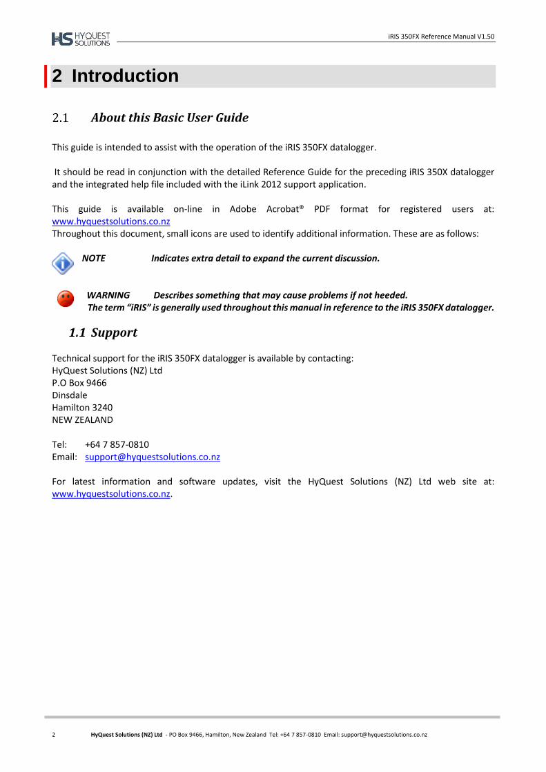
This guide is intended to assist with the operation of the iRIS 350FX datalogger. It should be read in conjunction with the detailed Reference Guide for the preceding iRIS 350X datalogger and the integrated help file included with the iLink 2012 support application. This guide is available on-line in Adobe Acrobat® PDF format for registered users at: www.hyquestsolutions.co.nz Throughout this document, small icons are used to identify additional information. These are as follows:
NOTE Indicates extra detail to expand the current discussion.
WARNING Describes something that may cause problems if not heeded. The term “iRIS” is generally used throughout this manual in reference to the iRIS 350FX datalogger.
1.1 Support Technical support for the iRIS 350FX datalogger is available by contacting: HyQuest Solutions (NZ) Ltd P.O Box 9466 Dinsdale Hamilton 3240 NEW ZEALAND Tel: +64 7 857-0810 Email: [email protected] For latest information and software updates, visit the HyQuest Solutions (NZ) Ltd web site at: www.hyquestsolutions.co.nz.
iRIS 350FX Reference Manual V1.50
3 HyQuest Solutions (NZ) Ltd - PO Box 9466, Hamilton, New Zealand Tel: +64 7 857-0810 Email: [email protected]
3 Overview
Introduction
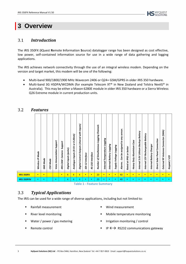
The iRIS 350FX (iQuest Remote Information Source) datalogger range has been designed as cost effective, low power, self-contained information source for use in a wide range of data gathering and logging applications. The iRIS achieves network connectivity through the use of an integral wireless modem. Depending on the version and target market, this modem will be one of the following:
Multi-band 900/1800/1900 MHz Wavecom 2406 or Q24+ GSM/GPRS in older iRIS 350 hardware.
Multi-band 3G HSDPA/WCDMA (for example Telecom XT® in New Zealand and Telstra NextG® in Australia). This may be either a Maxon 6280E module in older iRIS 350 hardware or a Sierra Wireless Q26 Extreme module in current production units.
Features
Wir
eles
s IP
Mo
de
SMS
Mo
de
CSD
Mo
de
Vo
ice
An
nu
nci
ati
on
Su
pp
ort
IRIS
-CA
M C
am
era
Su
pp
ort
Dig
ita
l in
pu
ts (
pu
lse)
.
An
alo
gu
e In
pu
ts (
0-5
V o
r 0-
20
mA
)
Dig
ita
l Co
ntr
ol O
utp
uts
(sh
are
d w
ith
inp
uts
)
SDI-
12
Inte
rfa
ce
RS-
232
Inte
rfa
ce
Nu
mb
er o
f Si
mu
lta
neo
us
Log
gin
g C
ha
nn
els
Inte
rna
l Tem
per
atu
re L
og
gin
g
Inte
rna
l Ba
tter
y Lo
gg
ing
Sup
ply
Vo
lta
ge
Log
gin
g
Ala
rms
. Ca
n b
e a
ssig
ned
to
an
y se
nso
r.
Ra
ted
at
IP6
5 o
r b
ette
r
Hea
vy D
uty
Alu
min
ium
Ca
se
Inte
rna
l 3.6
V L
ith
ium
Ba
cku
p B
att
ery
Inte
rna
l 12
V R
ech
arg
eab
le B
att
ery
Inte
rna
l Ba
tter
y C
ha
rger
Dir
ect
Sola
r P
an
el C
on
nec
tio
n
Exte
rna
l RF
An
ten
na
Co
nn
ecto
r (S
MA
)
Key
pa
d /
LC
D
iRIS 350FX 4 4 4 20 40
iRIS 350FXV 4 4 4 20 40
Table 1 - Feature Summary
Typical Applications
The iRIS can be used for a wide range of diverse applications, including but not limited to:
Rainfall measurement
River level monitoring
Water / power / gas metering
Remote control
Wind measurement
Mobile temperature monitoring
Irrigation monitoring / control
IP RS232 communications gateway
iRIS 350FX Reference Manual V1.50
4 HyQuest Solutions (NZ) Ltd - PO Box 9466, Hamilton, New Zealand Tel: +64 7 857-0810 Email: [email protected]
Key Features
Terminal Diagnostics
A small number of diagnostic and initialisation options are available via a standard ASCII terminal connected to the RS232 serial interface. In previous models (350 / 350X) nearly all the configuration was also done using the terminal. This has been removed because of the increased features of the FX and data unloading is done using the HyQuest Solutions logger support application, iLink 2012.
Wireless IP Connectivity
Wireless Internet Protocol connectivity is provided via the on-board modem. Through this interface it is possible to perform configuration changes and retrieve logged data using HydroTel™ or iLink 2012 software. To facilitate IP connectivity, a suitably activated SIM card must be inserted in the device. It is also necessary to program the unit with appropriate IP connection settings through a terminal connected to the RS232 serial interface. The iRIS communicates using IP over a wireless network using either UDP or TCP protocol.
Alternative Wireless Connectivity (SMS or FTP)
Another wireless connection mode other than IP is also possible on all hardware variants. This is SMS (Short Message Service). As with the IP mode described above in Section 3.4.2, using the SMS service requires a SIM card with the SMS service enabled by the service provider. The SMS option works by sending a pre-set text message to up to ten destination cell phones or SMS receivers. This message contains the iRIS site identification and the current values of all enabled sensors. See Section SMS Communication for more information on using the SMS feature.
Irrespective of the modem call-back mode setting (IP or SMS), the iRIS will only respond to incoming SMS requests when it is not connected in IP mode. The modem call-back mode setting only changes the service that is used to notify an alarm or generate a communications test. In this case, the selected service and destination phone numbers are used to send a text message (SMS).
Finally, FTP file transfer is provided for installations requiring a stand-alone data uploads. This option is only available for units equipped with the Sierra Wireless Q26 modem.
Power Management
The iRIS supports four power management modes which are described below. Power management features that operate in all modes include:
Deactivation of RS232 driver chip when the DSR signal is not present (unless the unit is active in RS232 telemetry mode).
Turning off the backlight after a period of inactivity when no user is logged-in.
Ability to activate an IP session at scheduled times of day for pre-set period even if the modem is otherwise disabled in full power save mode.
No Power Save
With power management disabled, the internal wireless modem is maintained in a powered on state even if an IP session is not currently active. While in this state, periodic signal strength measurements are made and

iRIS 350FX Reference Manual V1.50
5 HyQuest Solutions (NZ) Ltd - PO Box 9466, Hamilton, New Zealand Tel: +64 7 857-0810 Email: [email protected]
it is possible to interrogate the internal modem using the AT command set via a terminal connected to the serial interface. All on-board communication, I/O and all status LED’s are permanently enabled in this mode.
Partial Power Save
With the power management mode set to Partial Save, the on-board LEDs are disabled but the internal wireless modem remains in the same fully active state as in the No Power Save mode.
Full Power Save
When power management is set to full save mode, the internal LEDs are disabled and the internal wireless modem remains in a powered off state until a wireless session is activated by the scheduler, a user or an alarm (if this feature is enabled).
While the modem is in this state, it is not possible to obtain signal strength measurements or interrogate the modem via the AT command set using the Modem Terminal mode as the modem is shut down.
RS232 Only
This mode is provided for applications where the internal modem is not used and telemetry is achieved by a data radio or modem connected to the RS232 port. When in this mode, the RS232 port is used for all call-back communication. The RS232 port behaviour also changes depending on whether the iRIS is in “Normal” or “Telemetry” mode. See Section RS232 Interface Telemetry for further details on RS232 telemetry communications.
Data Logging
The iRIS supports the logging of data from up to twenty virtual sensors. Each of the virtual sensors can obtain information from one of the following data sources:
Analogue input on AIN1 – AIN4
Pulse counter attached to DIO1 - DIO4
Simulated pulse counter enabled by DIO1 - DIO4
Frequency counter attached to DIO1 or DIO2
Up/down counter attached to DIO1 and DIO2 simultaneously
Internal database location (for values obtained via user script or communications link)
SDI-12 instrument channel
Quadrature shaft encoder attached to DIO3 and DIO4 simultaneously
Change of status on charger input (dc supply)
Battery voltage
Supply (charger) voltage
Logger temperature
Received Signal Strength Indication (RSSI)
Derived via a lookup table (e.g. flow rate) sourced from sensor 1's measured value.
Change Of State on digital I/O channels DIO1 - DIO4 Each sensor can be set up to scale the raw data source into engineering units through the application of a multiplier and offset (slope and constant). The scaled value can be logged to non-volatile memory at rates between once per minute to once per hour or immediately in true event mode for pulse inputs.

iRIS 350FX Reference Manual V1.50
6 HyQuest Solutions (NZ) Ltd - PO Box 9466, Hamilton, New Zealand Tel: +64 7 857-0810 Email: [email protected]
It is also possible to configure a sensor to also log associated values such as minimum, maximum, standard deviation (for all source types) or a calculated flow rate or volume (pulse type sources only). See the next section for further details on configuring these extended logging features as part of the Sensor Cfg menus.
Logged Data Array Identification
Each sensor’s logged data is identified by an array ID number. For the primary logged data, the ID is the sensor number itself. For the optional supplementary data (min, max, deviation, flow/vol), the array ID has an offset added to the sensor number that it is associated with. These ID offsets are as follows:
Minimum: +20 Maximum: +40 Deviation: +60 Flow/Volume +80 Check Count +100
For example, Sensor 4 has been configured to log the average value, plus the maximum and standard deviation. Three data arrays will be logged for this sensor at each logging interval with IDs of 4, 44 and 64 respectively. In HydroTel™ these require point identifiers of 4, 44 and 64 respectively.
Array 0 (zero) is a special array identifier and is used as a system event log. Currently this is only used to log a restart (either at the initial connection of power, on a watchdog reset or a user program start after an upgrade). The logged value in this case contains a value that can be decoded to determine the cause of the restart. In HydroTel the identifier for this item is 0.
Alarm Processing
There is a “pool” of up to 40 free-format alarms. These can be assigned to any virtual sensor. So it is possible to have up to two alarms on every sensor or else more on some sensors and less or none on others. Each alarm has separate trigger and reset levels, and also an activation delay or accumulation period depending upon the data type. Each sensor has an associated flag that is set if any alarm on the sensor is active. This can be used to vary the logging rate for the sensor. For example taking more frequent logs when water level is high compared to a less frequent “routine” log in normal conditions. The iRIS also maintains a global “alarms active” flag that is set if any alarm on any sensor in the device is active. This is used to trigger a call-in or data transfer to the designated host. As well as the call-in, this flag can also control the digital outputs or trigger a camera image for the iRIS-CAM variant.
Real Time Clock & Calendar
The iRIS has a non-volatile real time clock that can be read and/or synchronised using HydroTel™ or iLink 2012.
The iRIS 350FX differs from its predecessors in that the internal clock runs in UTC (GMT) and all logged data is time/date stamped in this time zone. HydroTel™ and/or iLink 2012 automatically adjust for this. The configured UTC offset is only used to adjust the date/times on the LCD (as viewed by users) to the local standard time zone.
iRIS 350FX Reference Manual V1.50
7 HyQuest Solutions (NZ) Ltd - PO Box 9466, Hamilton, New Zealand Tel: +64 7 857-0810 Email: [email protected]
Security
The iRIS can be configured with a PIN code to prevent unauthorised access to restricted information through the LCD and keypad. This is especially useful when the iRIS is installed in a location where it is accessible to the general public. A second level of security is also provided to prevent access to the terminal via a serial connection. This is achieved by a security string that if used requires correct entry before access to the terminal is granted. This is typically to protect the totalisers and logged data from being cleared. See Section 6.2 for more details on using the security string.
Gateway Communication
The iRIS supports iQuest protocol gateway functionality between the wireless network and the RS232 serial interface. This enables the unit to be used as a bridge between the wide area wireless network and a localised radio or other network. It is possible to connect a datalogger that does not have wireless capability such as the HyQuest DS-4483 to the serial port of the iRIS and communicate with it via the gateway. Also, by connecting a data radio to the unit’s serial port it is possible to communicate with several devices in a multi-drop radio network from the wireless network. When the gateway option is enabled, any data packets that are not addressed to the iRIS and match the gateway criteria are readdressed and redirected. The port that the redirected packet is sent from depends on the configuration of the iRIS.
Refer to the Section RS232 Interface Telemetry for further information on using the gateway.
iRIS 350FX Reference Manual V1.50
8 HyQuest Solutions (NZ) Ltd - PO Box 9466, Hamilton, New Zealand Tel: +64 7 857-0810 Email: [email protected]
4 iRIS 350X and iRIS 350FX Comparison
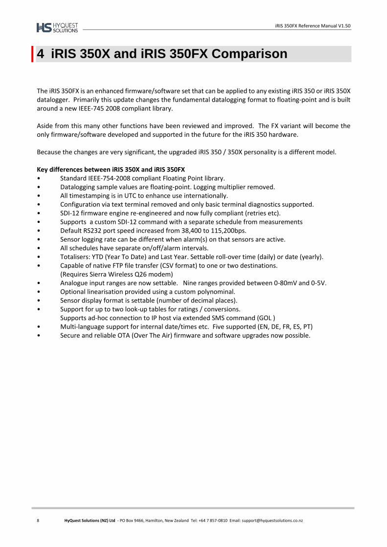
The iRIS 350FX is an enhanced firmware/software set that can be applied to any existing iRIS 350 or iRIS 350X datalogger. Primarily this update changes the fundamental datalogging format to floating-point and is built around a new IEEE-745 2008 compliant library. Aside from this many other functions have been reviewed and improved. The FX variant will become the only firmware/software developed and supported in the future for the iRIS 350 hardware. Because the changes are very significant, the upgraded iRIS 350 / 350X personality is a different model.
Key differences between iRIS 350X and iRIS 350FX • Standard IEEE-754-2008 compliant Floating Point library. • Datalogging sample values are floating-point. Logging multiplier removed. • All timestamping is in UTC to enhance use internationally. • Configuration via text terminal removed and only basic terminal diagnostics supported. • SDI-12 firmware engine re-engineered and now fully compliant (retries etc). • Supports a custom SDI-12 command with a separate schedule from measurements • Default RS232 port speed increased from 38,400 to 115,200bps. • Sensor logging rate can be different when alarm(s) on that sensors are active. • All schedules have separate on/off/alarm intervals. • Totalisers: YTD (Year To Date) and Last Year. Settable roll-over time (daily) or date (yearly). • Capable of native FTP file transfer (CSV format) to one or two destinations.
(Requires Sierra Wireless Q26 modem) • Analogue input ranges are now settable. Nine ranges provided between 0-80mV and 0-5V. • Optional linearisation provided using a custom polynominal. • Sensor display format is settable (number of decimal places). • Support for up to two look-up tables for ratings / conversions. Supports ad-hoc connection to IP host via extended SMS command (GOL ) • Multi-language support for internal date/times etc. Five supported (EN, DE, FR, ES, PT) • Secure and reliable OTA (Over The Air) firmware and software upgrades now possible.
iRIS 350FX Reference Manual V1.50
9 HyQuest Solutions (NZ) Ltd - PO Box 9466, Hamilton, New Zealand Tel: +64 7 857-0810 Email: [email protected]
5 Installation
Opening / Closing the Housing
The front of the iRIS enclosure is secured by four M4 machine screws with Phillips® heads.
There are two small plastic hinges on the case. These are designed to hold the lid once it is released.
To Open: Lift off the two grey plastic side covers to expose the screws securing the cover. Put them in a safe place. Undo all four screws. There is no need to remove them completely as they are
retained in the lid. The front cover should then be able to be swung open, to a maximum angle of 90. To Close: Check that the black sealing strip is fully installed in its retaining groove and there are no wires likely to be trapped under the cover. Gently swing the front cover closed, holding it straight while refitting the screws. Tighten screws securely to maintain the IP66 rating of the enclosure. Replace the grey plastic side covers. Finally ensure the black rubber sealing cap is refitted to protect the RS232 connector.
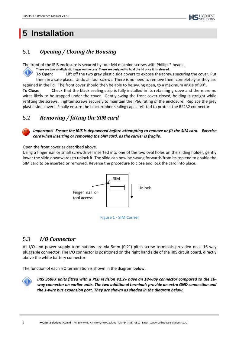
Removing / fitting the SIM card
Important! Ensure the iRIS is depowered before attempting to remove or fit the SIM card. Exercise care when inserting or removing the SIM card, as the carrier is fragile.
Open the front cover as described above. Using a finger nail or small screwdriver inserted into one of the two oval holes on the sliding holder, gently lower the slide downwards to unlock it. The slide can now be swung forwards from its top end to enable the SIM card to be inserted or removed. Reverse the procedure to close and lock the card into place.
Figure 1 - SIM Carrier
I/O Connector
All I/O and power supply terminations are via 5mm (0.2”) pitch screw terminals provided on a 16-way pluggable connector. The I/O connector is positioned on the right hand side of the iRIS circuit board, directly above the white battery connector. The function of each I/O termination is shown in the diagram below.
iRIS 350FX units fitted with a PCB revision V1.2+ have an 18-way connector compared to the 16-way connector on earlier units. The two additional terminals provide an extra GND connection and the 1-wire bus expansion port. They are shown as shaded in the diagram below.
Finger nail or tool access
Unlock
SIM

iRIS 350FX Reference Manual V1.50
10 HyQuest Solutions (NZ) Ltd - PO Box 9466, Hamilton, New Zealand Tel: +64 7 857-0810 Email: [email protected]
Figure 2 - I/O Connector
Internal Battery
The iRIS is supplied with an internal rechargeable 12V 0.8A/Hr sealed lead-acid battery. Upon installation, you will need to connect this battery as it is shipped disconnected to preserve battery life. It should also be disconnected if the unit is not going to be used for some time. For maximum flexibility, the iRIS I/O connector has two terminals provided for additional 12V power supply flexibility. These terminals (marked 12V+ and GND) can either be used to deliver 12V from the internal battery out to power an external sensor or other small load, or alternatively be connected to an external 12V battery (for greater battery capacity) or a 12Vdc battery charger type power supply. See the next two sections on using the 12V terminals and the external (charger) power supply feature.
TOP
OW 1-Wire Expansion Port (PCB Rev 1.2 +) GND Digital Common Ground (PCB Rev 1.2 +) AIN4 Analogue Input #4 AIN3 Analogue Input #3 AIN2 Analogue Input #2 AIN1 Analogue Input #1 Wire AGND Analogue Common Ground Entry AOUT Variable Analogue Output ((0-5V or 4-20mA) Side DIO4 Digital Input/Output #4 DIO3 Digital Input/Output #3 DIO2 Digital Input/Output #2 DIO1 Digital Input/Output #1 SDI SDI-12 Data Bus DGND Digital Common Ground 12V+ 12Vdc Internal/External Battery Supply + GND (-) 0Vdc Internal/External Battery Supply - VIN+ 15-30Vdc External Power Supply (Charger Input) + GND (-) 0Vdc External Power Supply (Charger Input) -
BOTTOM
WARNING! INTERNAL BATTERY
The 12V+ and GND terminals of the I/O connector are effectively connected directly in parallel with the internal 12V battery. A resettable semiconductor fuse is fitted for short-circuit protection. However, only connect 12V lead-acid batteries or a regulated d.c power supply that is designed for charging a 12V lead-acid battery, to these terminals. Applying a voltage higher than 14.5V for a sustained period to these terminals will permanently damage the internal battery and may cause an acid leak and/or an explosion.

iRIS 350FX Reference Manual V1.50
11 HyQuest Solutions (NZ) Ltd - PO Box 9466, Hamilton, New Zealand Tel: +64 7 857-0810 Email: [email protected]
Internal/External 12V Battery Supply
There are two terminals provided on the I/O connector designated +12V and GND. These can be used to power the unit from an external 12V battery or regulated dc supply. The internal battery is effectively connected directly to these terminals. See Section 5.3.1 above for warnings on connecting external power supplies to them.
External (Charger) Power Supply
Although the iRIS can operate solely from the internal battery for a few days if set to full power save mode, you will typically need to connect an external supply to the unit so that the internal battery remains in a charged state. You can connect any external dc power source ranging from 15 – 30Vdc, including a solar panel, without requiring an additional solar regulator. The battery charging circuitry utilises a switch mode regulator for maximum efficiency. The external power supply is protected against over-voltage by ultra-fast acting protection devices and a self-resetting semiconductor fuse. It can also be used to charge an external battery connected to the GND and 12V+ terminals. In the event that the external battery draws excessive current, the charger will enter a current limit mode (900mA) until such time as the battery has been recharged sufficiently to deliver the full supply voltage. The charging profile used by the charger depends on the selected mode. See the Power Management description in Section 6.3.2.
The battery charger operates in a simple dual mode “float” / “charge” pattern. To do this it regularly switches between two voltage levels to optimise the battery charge. The actual profile is determined by the Power Source setting. When the Power Source is set to “DC”, the battery voltage will rise and fall every two hours giving a “sawtooth” type voltage plot when the data is logged. This is normal.
Analogue I/O
Analogue Inputs
The four analogue inputs are uni-polar 0-5Vdc with 16-bit resolution. Each input presents a load impedance
of 97K to the input signal. Scaling factors should be chosen to convert from a raw value of 0.0000 – 5.0000, which reflects the input signal range of 0-5V. When current sources such as 0-20mA or 4-20mA are connected, an internal sink
resistor (100) is enabled by an internal user-settable link (J1-J4). In this mode the measured voltage range is 0-2V for a 0-20mA input and the scaling factor should take this into account.
As the analogue inputs have an input impedance of 97K, the actual sink resistor impedance will be slightly lower than the value fitted. When, for example, the current mode link is fitted, a sink
resistor of 100 ohms is installed. The actual impedance will theoretically be 99.71; therefore the voltage measured by the iRIS will also be slightly lower than expected. See Section 9 for details on the recommended scaling method for optimising the calibration.

iRIS 350FX Reference Manual V1.50
12 HyQuest Solutions (NZ) Ltd - PO Box 9466, Hamilton, New Zealand Tel: +64 7 857-0810 Email: [email protected]
Figure 3 - Simplified Analogue Input Circuit
Figure 4 - Analogue Input / Output Links
It is possible to use an external resistor such as a 250 Ω to raise the voltage range measured. I.e. 100Ω will give a working range of 0.4V to 2V, 250Ω will give a range of 1V to 5V. In this case, ensure the internal sink enable link is open. The resistor value in the analogue scaling calculator in iLink will need to be changed to the value actually used.
Analogue Output
The iRIS has a single variable analogue output. This may be configured to deliver either a voltage output ranging between 0-5V or a current output ranging from 4-20mA. The output's electrical signal (voltage or current) is link selectable. See Section 6.3.4.2 for details on configuring the analogue output.
Digital I/O
The iRIS has four digital I/O channels which can each be configured as either an input or output. When set as an output, the channel can either supply switched 12V or else act as a pull-down switch for loads with a different supply voltage. If the digital output configuration is set to 0 (Disabled) the channel is by default an input. See Section 6.3.4.1 for details on configuring the digital outputs.
1nF 22K
75K
AGND
AINx
To ADC
AIN4 100Ω current sink enable link (J1)
AIN1 100Ω current sink enable link (J4)
AIN3 100Ω current sink enable link (J2)
AIN2 100Ω current sink enable link (J3)
AOUT mode link. (J5) 4-20mA 0-5V (default)

iRIS 350FX Reference Manual V1.50
13 HyQuest Solutions (NZ) Ltd - PO Box 9466, Hamilton, New Zealand Tel: +64 7 857-0810 Email: [email protected]
Digital Channels as Inputs
The digital inputs are selectable for either mechanical or electronic operation. In either case it is necessary to pull the input down to 0Vdc to activate it. Inputs will handle up to 30Vdc in the off state for parallel connection across existing equipment. The “debounce” is enabled by a jumper link, which if fitted enables a longer time constant circuit to eliminate multiple pulses caused by contact bounce. The debounce jumpers are positioned in the centre of the PCB. The picture below shows the links in their default positions.
Figure 5 - Digital Input Debounce Links
Fit the jumper for mechanical switching at up to 20Hz. In this mode the input is normally pulled up to 12V
through a 10K resistor providing a wetting current of approximately 1.2mA. A 100nF capacitor is also fitted across the input to provide limited hardware debounce, preventing false triggering due to contact bounce. For installations that do not have an external power source it is important that the input is not held low for a prolonged period of time, as this will increase the current drawn from the internal battery. Remove the appropriate jumper for electronic switching at up to 5kHz (on DIO1 and DIO2 only). In this mode
the input is normally pulled up to 5V through a 57K resistance, providing a wetting current of approximately
100A.
Figure 6 - Digital Input Circuit
DIOx
DGND
100nF
JPx
1K
10K
+12V 5V
1nF
47K
To internal logic circuitry
DIO4 debounce link
DIO1 debounce link
iRIS 350FX Reference Manual V1.50
14 HyQuest Solutions (NZ) Ltd - PO Box 9466, Hamilton, New Zealand Tel: +64 7 857-0810 Email: [email protected]
Digital Outputs
When an iRIS digital I/O channel is configured as an output it can be operated electrically in one of two ways. Either: Open-drain Pull-down which is capable of sinking up to 100mA at 30Vdc. An integral diode provides transient protection. Typically this output mode can be used to drive a relay or lamp powered by an auxiliary d.c supply (e.g. 12V). In this mode, the negative of the load supply must be connected to one of the iRIS GND terminals.
Although it may appear possible to directly control sensors by switching the sensor negative supply lead using a digital output, this will introduce measurement errors and may possibly damage the sensor. Always use a digital output configured as a switched 12V output to power sensors.
Or: Switched 12V output which is capable of sourcing up to 100mA. Typically this output mode will be used to drive a sensor, relay or lamp powered by the iRIS’s 12V supply.
Care should be taken to avoid the load discharging the internal and/or external 12V battery. Ensure adequate power supply charging capacity is available to cater for the demands of both the logger and load.
The digital outputs may also be programmed to follow the state of the IP connection so that they will be active when a wireless IP session has been established. This mode can be used to control power to an external data radio when using the iRIS as a radio based gateway. Typically, an output is configured to follow a schedule for use in powering loads. There is a similar mode termed "Schedule Plus".
In "Schedule Plus"mode, the relevant output(s) will be activated when a user is logged on to allow sensor calibration or radio communication testing. It will also activate when a call-in is pending and the Power Save mode is set to RS232 Telemetry to allow communications equipment to be powered
up.
IMPORTANT NOTE! In almost all installations where an iRIS is connected in parallel with other equipment to share a common pulse input (e.g. from a flow meter), there has not been a detrimental effect, as the iRIS inputs present a relatively high impedance to the circuit. However, in the event that connecting an iRIS does cause pulse failure, HyQuest Solutions recommend removing the debounce selection link for the appropriate input. This sets the input to electronic switching mode, even if the actual pulse source is a clean contact (reed switch or similar). The debounce jumpers are located in the center of the PCB and can be accessed once the front cover is opened. See Figure 5 above. Hint: When removing a jumper, simply fit it to one pin only of the connector to avoid it being lost.
iRIS 350FX Reference Manual V1.50
15 HyQuest Solutions (NZ) Ltd - PO Box 9466, Hamilton, New Zealand Tel: +64 7 857-0810 Email: [email protected]
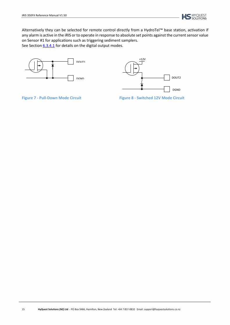
Alternatively they can be selected for remote control directly from a HydroTel™ base station, activation if any alarm is active in the iRIS or to operate in response to absolute set points against the current sensor value on Sensor #1 for applications such as triggering sediment samplers. See Section 6.3.4.1 for details on the digital output modes.
Figure 7 - Pull-Down Mode Circuit Figure 8 - Switched 12V Mode Circuit
DOUT1
DGND DOUT2
+12V
DGND
iRIS 350FX Reference Manual V1.50
16 HyQuest Solutions (NZ) Ltd - PO Box 9466, Hamilton, New Zealand Tel: +64 7 857-0810 Email: [email protected]
6 Configuration
The iRIS configuration is done by iLink 2012 or HydroTel. A limited terminal tool is available via the RS232 port for local SDI-12 diagnostics. This description assumes a computer running the Microsoft® Windows® operating system is being used and all examples relate to the configuration tool in iLink 2012.
Terminal Connection
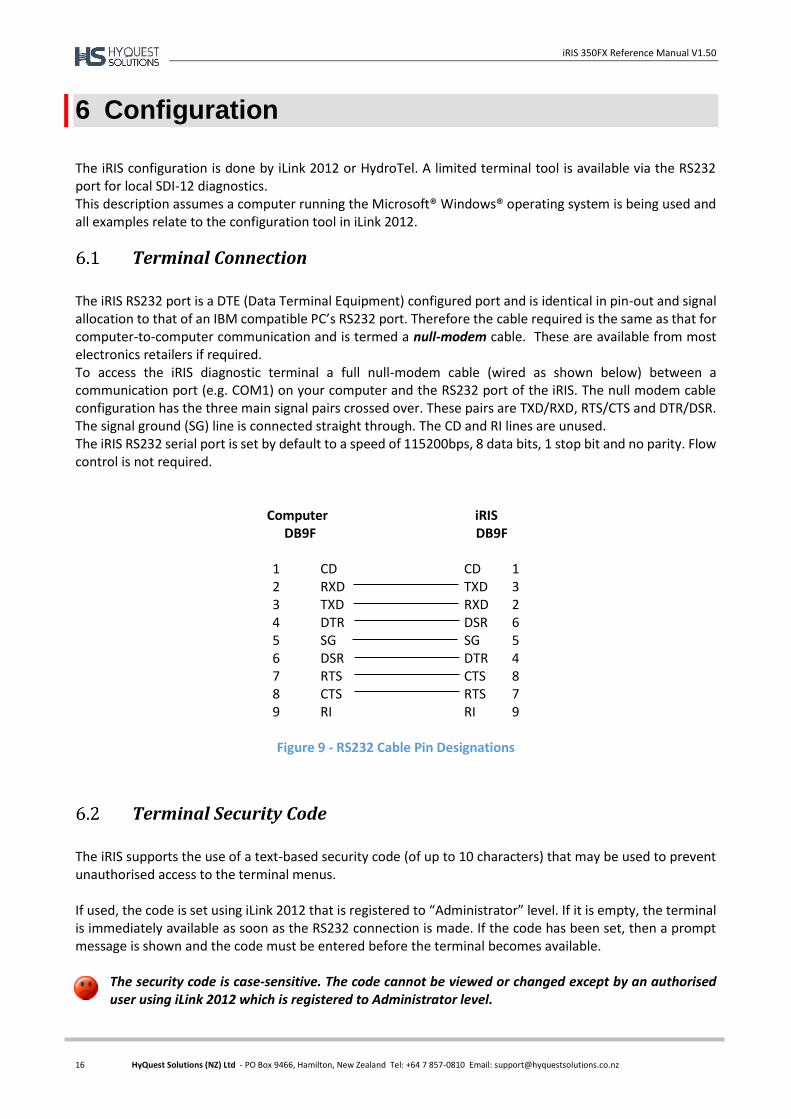
The iRIS RS232 port is a DTE (Data Terminal Equipment) configured port and is identical in pin-out and signal allocation to that of an IBM compatible PC’s RS232 port. Therefore the cable required is the same as that for computer-to-computer communication and is termed a null-modem cable. These are available from most electronics retailers if required. To access the iRIS diagnostic terminal a full null-modem cable (wired as shown below) between a communication port (e.g. COM1) on your computer and the RS232 port of the iRIS. The null modem cable configuration has the three main signal pairs crossed over. These pairs are TXD/RXD, RTS/CTS and DTR/DSR. The signal ground (SG) line is connected straight through. The CD and RI lines are unused. The iRIS RS232 serial port is set by default to a speed of 115200bps, 8 data bits, 1 stop bit and no parity. Flow control is not required.
Computer iRIS DB9F DB9F
1 CD CD 1 2 RXD TXD 3 3 TXD RXD 2 4 DTR DSR 6 5 SG SG 5 6 DSR DTR 4 7 RTS CTS 8 8 CTS RTS 7 9 RI RI 9
Figure 9 - RS232 Cable Pin Designations
Terminal Security Code
The iRIS supports the use of a text-based security code (of up to 10 characters) that may be used to prevent unauthorised access to the terminal menus. If used, the code is set using iLink 2012 that is registered to “Administrator” level. If it is empty, the terminal is immediately available as soon as the RS232 connection is made. If the code has been set, then a prompt message is shown and the code must be entered before the terminal becomes available.
The security code is case-sensitive. The code cannot be viewed or changed except by an authorised user using iLink 2012 which is registered to Administrator level.
iRIS 350FX Reference Manual V1.50
17 HyQuest Solutions (NZ) Ltd - PO Box 9466, Hamilton, New Zealand Tel: +64 7 857-0810 Email: [email protected]
Configuration Menus
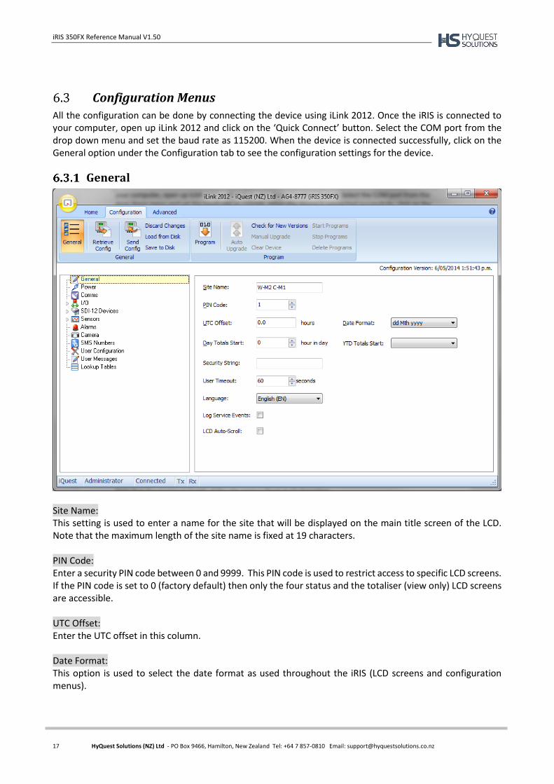
All the configuration can be done by connecting the device using iLink 2012. Once the iRIS is connected to your computer, open up iLink 2012 and click on the ‘Quick Connect’ button. Select the COM port from the drop down menu and set the baud rate as 115200. When the device is connected successfully, click on the General option under the Configuration tab to see the configuration settings for the device.
General
Site Name: This setting is used to enter a name for the site that will be displayed on the main title screen of the LCD. Note that the maximum length of the site name is fixed at 19 characters. PIN Code: Enter a security PIN code between 0 and 9999. This PIN code is used to restrict access to specific LCD screens. If the PIN code is set to 0 (factory default) then only the four status and the totaliser (view only) LCD screens are accessible. UTC Offset: Enter the UTC offset in this column. Date Format: This option is used to select the date format as used throughout the iRIS (LCD screens and configuration menus).

iRIS 350FX Reference Manual V1.50
18 HyQuest Solutions (NZ) Ltd - PO Box 9466, Hamilton, New Zealand Tel: +64 7 857-0810 Email: [email protected]
Day Totals Start: This option allows you to enter the hour of the day to start calculating the day totals. YTD Totals Start: Enter the month of the year to start calculating the year to date totals. Security String: The Security String (of up to 10 characters) is used to prevent unauthorized access to the terminal menus. If used, the code is set using iLink 2012 that is registered to "Administrator" level. If it is empty, the terminal is immediately available as soon as the RS232 connection is made. If the code has been set, then a prompt message is shown and the code must be entered before the terminal becomes available. User Timeout: You can set the user to be logged off automatically after a certain period of no key presses. Enter the time in seconds in this column. Language: Choose the language from the available options (English, German, French, Spanish and Portuguese). Log Service Events: If this option is enabled, all the service events will be logged. LCD Auto-Scroll: Ticking this option will enable the LCD screens to scroll automatically.
iRIS 350FX Reference Manual V1.50
19 HyQuest Solutions (NZ) Ltd - PO Box 9466, Hamilton, New Zealand Tel: +64 7 857-0810 Email: [email protected]
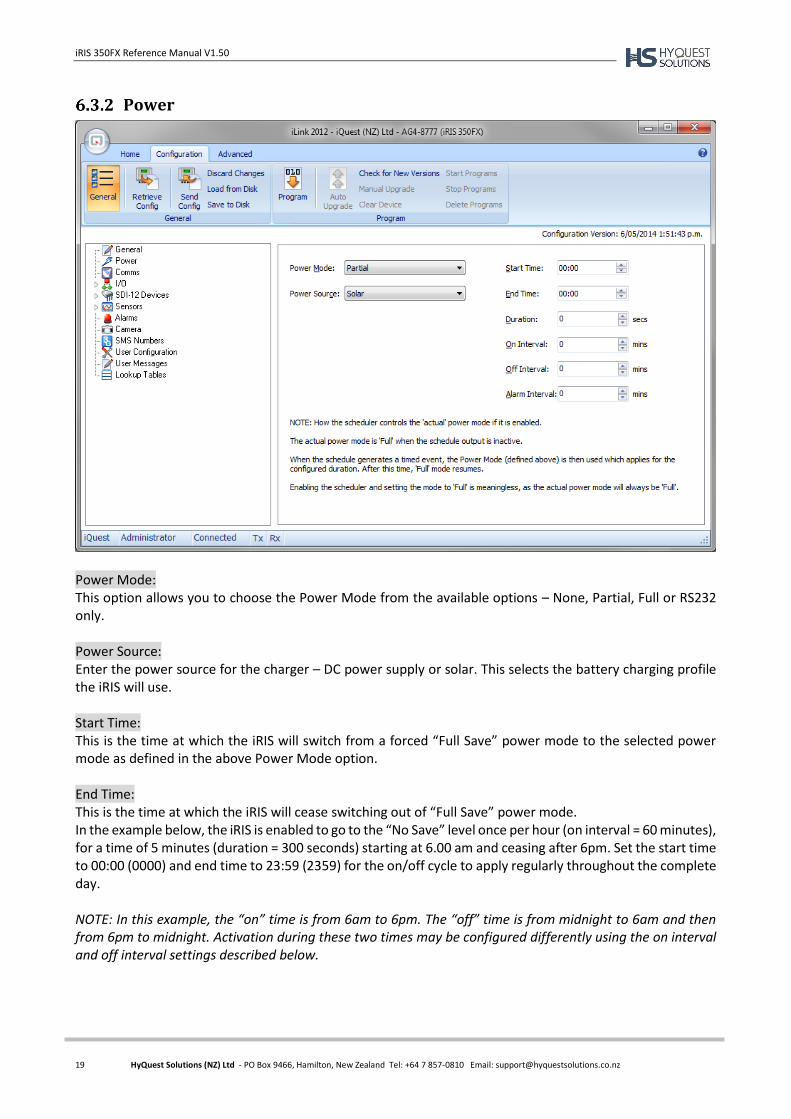
Power
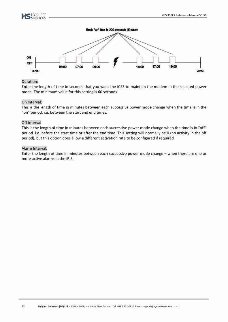
Power Mode: This option allows you to choose the Power Mode from the available options – None, Partial, Full or RS232 only. Power Source: Enter the power source for the charger – DC power supply or solar. This selects the battery charging profile the iRIS will use. Start Time: This is the time at which the iRIS will switch from a forced “Full Save” power mode to the selected power mode as defined in the above Power Mode option. End Time: This is the time at which the iRIS will cease switching out of “Full Save” power mode. In the example below, the iRIS is enabled to go to the “No Save” level once per hour (on interval = 60 minutes), for a time of 5 minutes (duration = 300 seconds) starting at 6.00 am and ceasing after 6pm. Set the start time to 00:00 (0000) and end time to 23:59 (2359) for the on/off cycle to apply regularly throughout the complete day. NOTE: In this example, the “on” time is from 6am to 6pm. The “off” time is from midnight to 6am and then from 6pm to midnight. Activation during these two times may be configured differently using the on interval and off interval settings described below.
iRIS 350FX Reference Manual V1.50
20 HyQuest Solutions (NZ) Ltd - PO Box 9466, Hamilton, New Zealand Tel: +64 7 857-0810 Email: [email protected]
Duration: Enter the length of time in seconds that you want the iCE3 to maintain the modem in the selected power mode. The minimum value for this setting is 60 seconds. On Interval: This is the length of time in minutes between each successive power mode change when the time is in the “on” period. i.e. between the start and end times. Off Interval This is the length of time in minutes between each successive power mode change when the time is in “off” period. i.e. before the start time or after the end time. This setting will normally be 0 (no activity in the off period), but this option does allow a different activation rate to be configured if required. Alarm Interval: Enter the length of time in minutes between each successive power mode change – when there are one or more active alarms in the iRIS.
iRIS 350FX Reference Manual V1.50
21 HyQuest Solutions (NZ) Ltd - PO Box 9466, Hamilton, New Zealand Tel: +64 7 857-0810 Email: [email protected]
Comms
The comms configuration menu is the starting point for configuring all iRIS communication settings:
6.3.3.1 Addressing
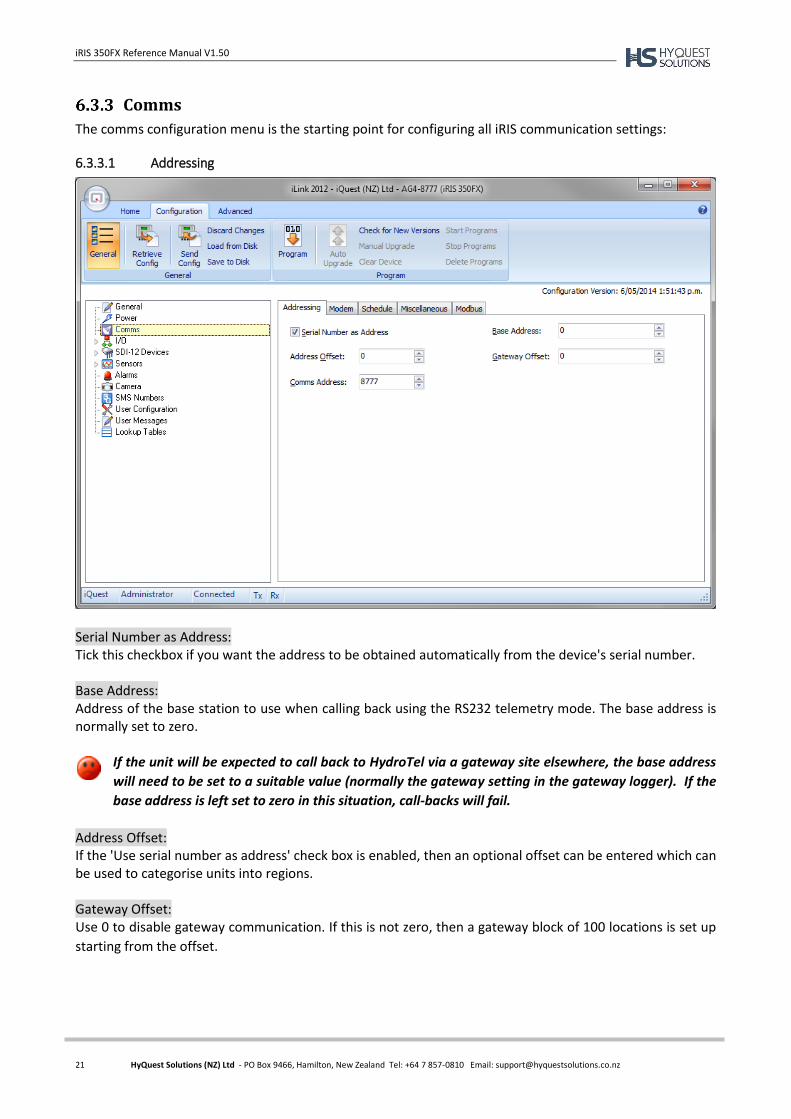
Serial Number as Address: Tick this checkbox if you want the address to be obtained automatically from the device's serial number. Base Address: Address of the base station to use when calling back using the RS232 telemetry mode. The base address is normally set to zero.
If the unit will be expected to call back to HydroTel via a gateway site elsewhere, the base address
will need to be set to a suitable value (normally the gateway setting in the gateway logger). If the
base address is left set to zero in this situation, call-backs will fail.
Address Offset: If the 'Use serial number as address' check box is enabled, then an optional offset can be entered which can be used to categorise units into regions. Gateway Offset: Use 0 to disable gateway communication. If this is not zero, then a gateway block of 100 locations is set up
starting from the offset.
iRIS 350FX Reference Manual V1.50
22 HyQuest Solutions (NZ) Ltd - PO Box 9466, Hamilton, New Zealand Tel: +64 7 857-0810 Email: [email protected]
The RS232 Only gateway mode is different to the wireless IP to RS232 bridge mode that requires a
special cable to invoke. See Section 10, RS232 Interface Telemetry / Gateway Comms for more
detail on using gateway communication.
Comms address: If the automatic serial number mode is not enabled, enter the communication address for the device (the factory default is 1). This address is used to identify the unit in all iQuest protocol communication and must be unique on a HydroTel communications interface.
6.3.3.2 Modem
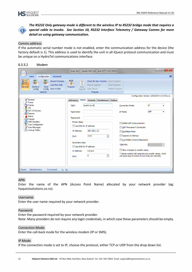
APN: Enter the name of the APN (Access Point Name) allocated by your network provider (eg: hyquestsolutions.co.nz). Username: Enter the user name required by your network provider. Password: Enter the password required by your network provider. Note: Many providers do not require any login credentials, in which case these parameters should be empty. Connection Mode: Enter the call-back mode for the wireless modem (IP or SMS). IP Mode: If the connection mode is set to IP, choose the protocol, either TCP or UDP from the drop down list.
iRIS 350FX Reference Manual V1.50
23 HyQuest Solutions (NZ) Ltd - PO Box 9466, Hamilton, New Zealand Tel: +64 7 857-0810 Email: [email protected]
Primary Base IP: Enter the remote IP address you want to have the iRIS connect to as its primary base (host server). Primary Base Port: Enter a non-zero port number to use for the IP socket. Secondary Base IP: Enter the optional secondary base remote IP address that you will connect to. This should be set to the same address as the primary base if there is only a single base. Secondary Base Port: Enter the remote port number for the optional secondary base. This should be set to the same port as the primary base if there is only a single base. Use DNS for IP Address: If this option is checked, the DNS Server address will be used for IP address. Inhibit UDP Announcement: If the IP Mode is set to UDP, this option controls whether the iRIS will send an announcement packet to the base station (HydroTel) when the IP connection is established. Normally, this option is disabled and HydroTel will initiate unloads of the iRIS each time it announces it is on-line. For installations where the iRIS is configured to be virtually on-line continually and polled by HydroTel, tick this checkbox. UDP ‘Permanent’ Connection: This option is used to enable a permanent UDP connection regardless of the schedule settings. TCP Server Up Time: If the IP Mode is set to TCP, this option defines the time in minutes that the iRIS will remain in a listening TCP Server mode after a TCP client session to the designated base station has been completed. Setting this parameter zero will disable the listening TCP server mode and the iRIS will return to idle mode immediately. TCP Server Mode only: If the IP Mode is set to TCP, this option enables to keep the iRIS remain in a listening TCP server mode. Dual Base Mode: When this mode is enabled and the secondary IP settings are configured, the iRIS will make a connection to both bases in sequence for each connection event (scheduler or manually triggered). Connect on Startup: This option enables the device to get connected upon startup. Log Modem Comms Diagnostics: Tick this option if you wish to log the modem comms diagnostics. SIM PIN: If the SIM card installed has a PIN code enabled for security purposes, use this option to define it. If a PIN code is not required, enter zero (0) for this setting.
iRIS 350FX Reference Manual V1.50
24 HyQuest Solutions (NZ) Ltd - PO Box 9466, Hamilton, New Zealand Tel: +64 7 857-0810 Email: [email protected]
If a SIM PIN is required and an incorrect PIN is entered, the unit will not operate correctly. Also, if the SIM PIN is set incorrectly, repeated attempts by the iRIS to log-on may result in the SIM card becoming locked out. This situation will require knowledge of the SIM’s PIN Unlock Key (PUK) and/or contacting the SIM provider for unlock details.
Allow Changes to Unsafe Values: The APN, Username and Password are marked as unsafe values, which may cause loss of comms if incorrectly set remotely. If you want to edit these columns, the option "Allow changes to unsafe values" should be enabled.
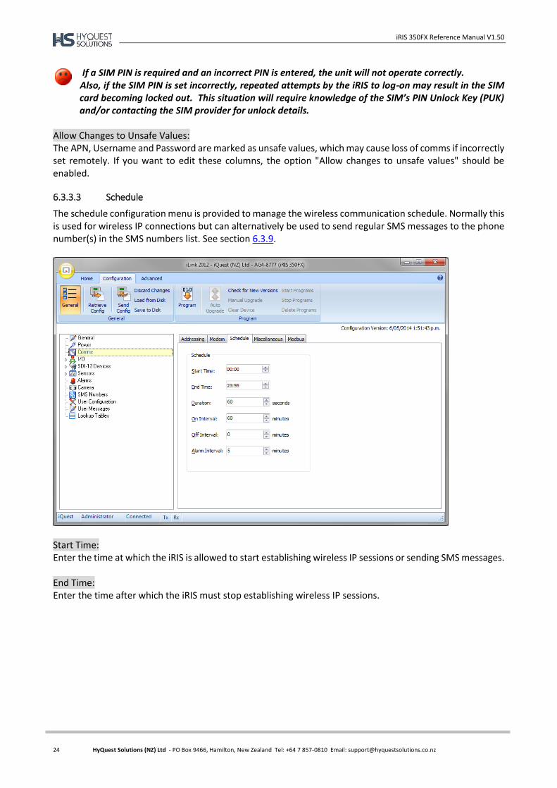
6.3.3.3 Schedule
The schedule configuration menu is provided to manage the wireless communication schedule. Normally this is used for wireless IP connections but can alternatively be used to send regular SMS messages to the phone number(s) in the SMS numbers list. See section 6.3.9.
Start Time: Enter the time at which the iRIS is allowed to start establishing wireless IP sessions or sending SMS messages. End Time: Enter the time after which the iRIS must stop establishing wireless IP sessions.
iRIS 350FX Reference Manual V1.50
25 HyQuest Solutions (NZ) Ltd - PO Box 9466, Hamilton, New Zealand Tel: +64 7 857-0810 Email: [email protected]
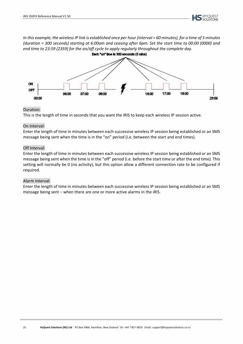
In this example, the wireless IP link is established once per hour (interval = 60 minutes), for a time of 5 minutes (duration = 300 seconds) starting at 6:00am and ceasing after 6pm. Set the start time to 00:00 (0000) and end time to 23:59 (2359) for the on/off cycle to apply regularly throughout the complete day.
Duration: This is the length of time in seconds that you want the iRIS to keep each wireless IP session active. On Interval: Enter the length of time in minutes between each successive wireless IP session being established or an SMS message being sent when the time is in the “on” period (i.e. between the start and end times). Off Interval: Enter the length of time in minutes between each successive wireless IP session being established or an SMS message being sent when the time is in the “off” period (i.e. before the start time or after the end time). This setting will normally be 0 (no activity), but this option allow a different connection rate to be configured if required. Alarm Interval: Enter the length of time in minutes between each successive wireless IP session being established or an SMS message being sent – when there are one or more active alarms in the iRIS.
iRIS 350FX Reference Manual V1.50
26 HyQuest Solutions (NZ) Ltd - PO Box 9466, Hamilton, New Zealand Tel: +64 7 857-0810 Email: [email protected]
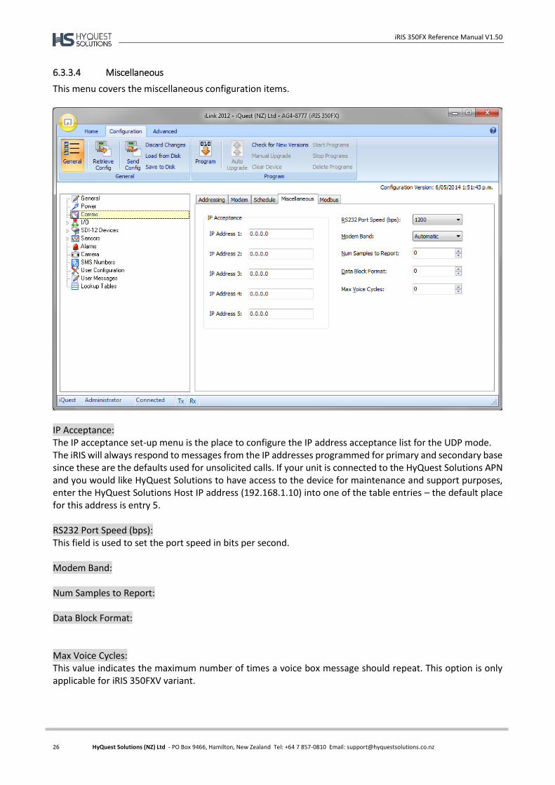
6.3.3.4 Miscellaneous
This menu covers the miscellaneous configuration items.
IP Acceptance: The IP acceptance set-up menu is the place to configure the IP address acceptance list for the UDP mode. The iRIS will always respond to messages from the IP addresses programmed for primary and secondary base since these are the defaults used for unsolicited calls. If your unit is connected to the HyQuest Solutions APN and you would like HyQuest Solutions to have access to the device for maintenance and support purposes, enter the HyQuest Solutions Host IP address (192.168.1.10) into one of the table entries – the default place for this address is entry 5. RS232 Port Speed (bps): This field is used to set the port speed in bits per second. Modem Band: Num Samples to Report: Data Block Format: Max Voice Cycles: This value indicates the maximum number of times a voice box message should repeat. This option is only applicable for iRIS 350FXV variant.
iRIS 350FX Reference Manual V1.50
27 HyQuest Solutions (NZ) Ltd - PO Box 9466, Hamilton, New Zealand Tel: +64 7 857-0810 Email: [email protected]
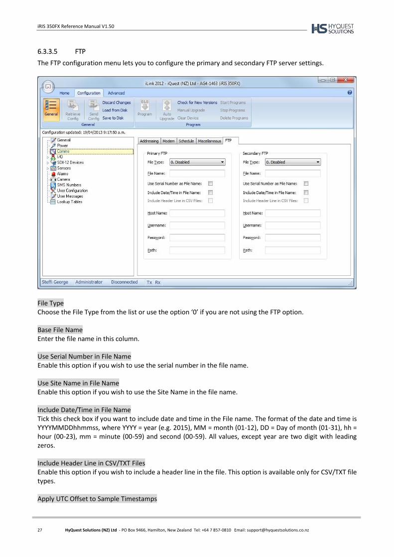
6.3.3.5 FTP
The FTP configuration menu lets you to configure the primary and secondary FTP server settings.
File Type Choose the File Type from the list or use the option ‘0’ if you are not using the FTP option. Base File Name Enter the file name in this column. Use Serial Number in File Name Enable this option if you wish to use the serial number in the file name. Use Site Name in File Name Enable this option if you wish to use the Site Name in the file name. Include Date/Time in File Name Tick this check box if you want to include date and time in the File name. The format of the date and time is YYYYMMDDhhmmss, where YYYY = year (e.g. 2015), MM = month (01-12), DD = Day of month (01-31), hh = hour (00-23), mm = minute (00-59) and second (00-59). All values, except year are two digit with leading zeros. Include Header Line in CSV/TXT Files Enable this option if you wish to include a header line in the file. This option is available only for CSV/TXT file types. Apply UTC Offset to Sample Timestamps
iRIS 350FX Reference Manual V1.50
28 HyQuest Solutions (NZ) Ltd - PO Box 9466, Hamilton, New Zealand Tel: +64 7 857-0810 Email: [email protected]
This option is used to apply UTC offset to sample timestamps. Host Name Enter the name of the host device. Username Enter the username required to login to the FTP server. Password Enter the password required to login to the FTP server.
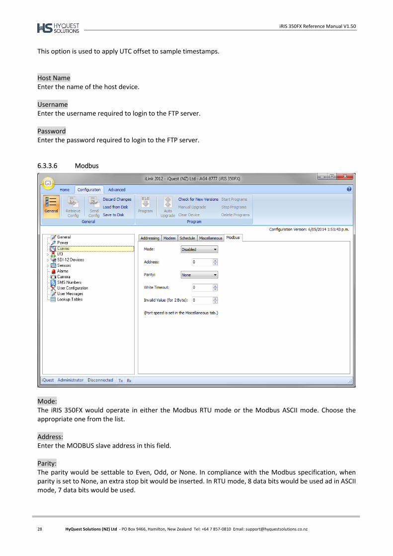
6.3.3.6 Modbus
Mode: The iRIS 350FX would operate in either the Modbus RTU mode or the Modbus ASCII mode. Choose the appropriate one from the list. Address: Enter the MODBUS slave address in this field. Parity: The parity would be settable to Even, Odd, or None. In compliance with the Modbus specification, when parity is set to None, an extra stop bit would be inserted. In RTU mode, 8 data bits would be used ad in ASCII mode, 7 data bits would be used.
iRIS 350FX Reference Manual V1.50
29 HyQuest Solutions (NZ) Ltd - PO Box 9466, Hamilton, New Zealand Tel: +64 7 857-0810 Email: [email protected]
Write Timeout: Number of minutes to wait for lack of write from master before setting sensor locations to either NaN for floating point sources and Invalid Value (see below) for integer sources. Setting the timeout to zero will disable this feature Invalid Value (for 2 Byte): This is the value that will be substituted for 2 byte sort registers when there is a communications timeout (see Write Timeout above).
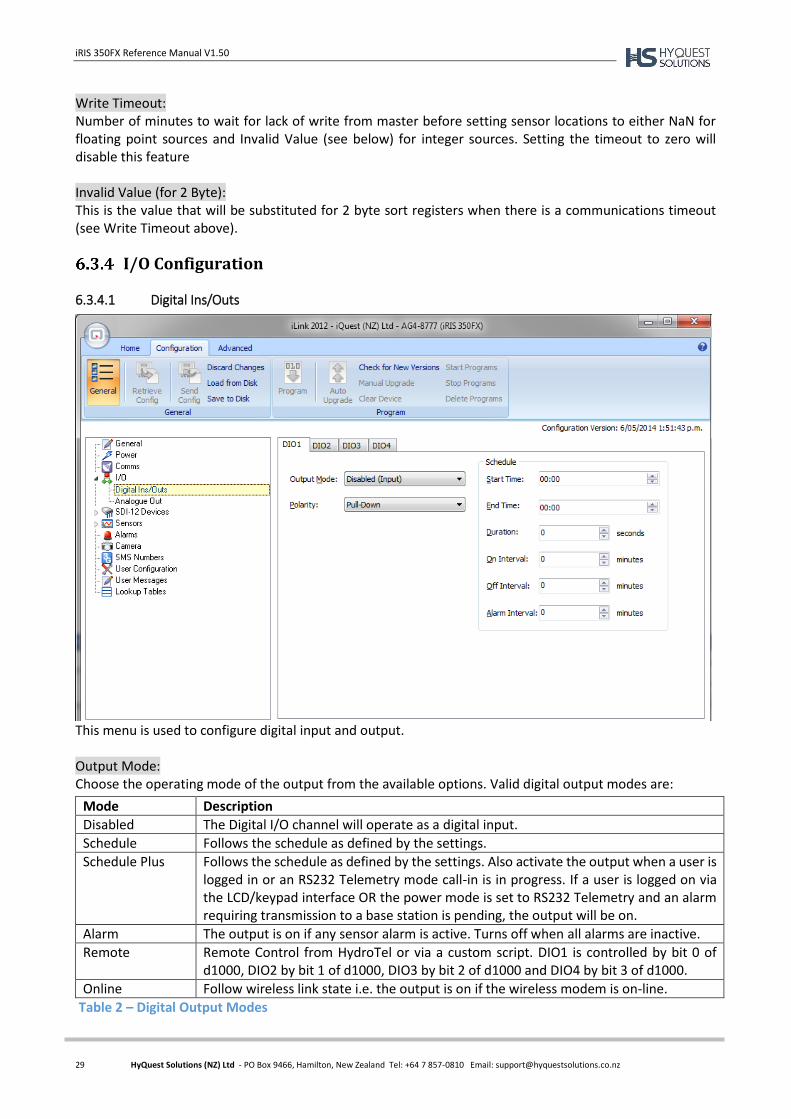
I/O Configuration
6.3.4.1 Digital Ins/Outs
This menu is used to configure digital input and output. Output Mode: Choose the operating mode of the output from the available options. Valid digital output modes are:
Table 2 – Digital Output Modes
Mode Description
Disabled The Digital I/O channel will operate as a digital input.
Schedule Follows the schedule as defined by the settings.
Schedule Plus Follows the schedule as defined by the settings. Also activate the output when a user is logged in or an RS232 Telemetry mode call-in is in progress. If a user is logged on via the LCD/keypad interface OR the power mode is set to RS232 Telemetry and an alarm requiring transmission to a base station is pending, the output will be on.
Alarm The output is on if any sensor alarm is active. Turns off when all alarms are inactive.
Remote Remote Control from HydroTel or via a custom script. DIO1 is controlled by bit 0 of d1000, DIO2 by bit 1 of d1000, DIO3 by bit 2 of d1000 and DIO4 by bit 3 of d1000.
Online Follow wireless link state i.e. the output is on if the wireless modem is on-line.
iRIS 350FX Reference Manual V1.50
30 HyQuest Solutions (NZ) Ltd - PO Box 9466, Hamilton, New Zealand Tel: +64 7 857-0810 Email: [email protected]
Polarity: Select the switching polarity of the output. This relates to the output’s electrical state with respect to its logical on/off state. It also defines whether the output type is a pull-down (switch to GND) or pull-up (switch 12V). Please refer to the table below.
Polarity Output Logical State Indication LED Output Electrical State
Normal Pull-Down Off Off Open-circuit (Input)
On On Pulled down to 0V (GND)
Inverted Pull-Down Off Off Pulled down to 0V (GND)
On On Open-circuit (Input)
Normal Pull-Up Off Off Open-circuit (Input)
On On Pulled up to +12V
Inverted Pull-Up Off Off Pulled up to +12V
On On Open-circuit (Input)
Table 3 – Digital Output Polarity
If the polarity setting is Normal, the output will be electrically on when the output logical state is on
and be high impedance (open-circuit) when the output is logically off.
If the polarity setting is Inverted, the output will be high impedance (open-circuit) when the output
logical state is on and be electrically on when the output is logically off.
If the polarity setting is Pull-Down, the output will short the output terminal to GND. A maximum
of 100mA can be sunk in this mode from an external load.
If the polarity setting is Pull-Up, the output will supply 12V to an external load at up to 100mA.
Start Time: This is the time at which the iRIS is allowed to start controlling the output if the mode is set to Schedule. End Time: This is the time at which the iRIS must stop controlling the output if the mode is set to Schedule. Duration: Enter the length of time in seconds that you want the iRIS to keep the output energised for if the mode is set to Schedule or Schedule Plus. Interval: Enter the length of time in minutes between the successive operations of the output if the mode is set to Schedule. Alarm Interval: Enter the length of time in minutes between the successive operations of the output if the mode is set to Schedule - when there are one or more active alarms in the iRIS.
iRIS 350FX Reference Manual V1.50
31 HyQuest Solutions (NZ) Ltd - PO Box 9466, Hamilton, New Zealand Tel: +64 7 857-0810 Email: [email protected]
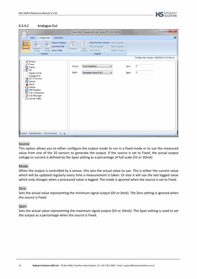
6.3.4.2 Analogue Out
Source: This option allows you to either configure the output mode to run in a fixed mode or to use the measured value from one of the 20 sensors to generate the output. If the source is set to Fixed, the actual output voltage or current is defined by the Span setting as a percentage of full-scale (5V or 20mA) Mode: When the output is controlled by a sensor, this sets the actual value to use. This is either the current value which will be updated regularly every time a measurement is taken. Or else it will use the last logged value which only changes when a processed value is logged. The mode is ignored when the source is set to Fixed. Zero: Sets the actual value representing the minimum signal output (0V or 0mA). The Zero setting is ignored when the source is Fixed. Span: Sets the actual value representing the maximum signal output (5V or 20mA). The Span setting is used to set the output as a percentage when the source is Fixed.
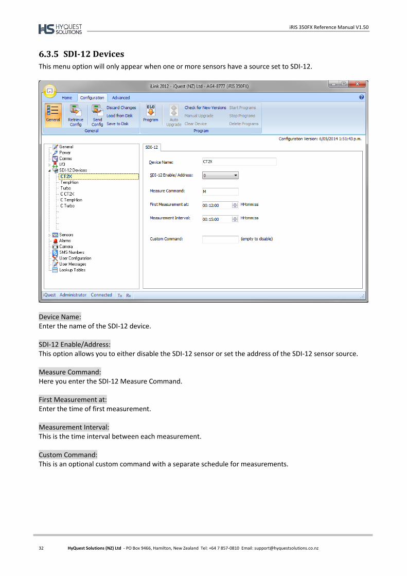
iRIS 350FX Reference Manual V1.50
32 HyQuest Solutions (NZ) Ltd - PO Box 9466, Hamilton, New Zealand Tel: +64 7 857-0810 Email: [email protected]
SDI-12 Devices
This menu option will only appear when one or more sensors have a source set to SDI-12.
Device Name: Enter the name of the SDI-12 device. SDI-12 Enable/Address: This option allows you to either disable the SDI-12 sensor or set the address of the SDI-12 sensor source. Measure Command: Here you enter the SDI-12 Measure Command. First Measurement at: Enter the time of first measurement. Measurement Interval: This is the time interval between each measurement. Custom Command: This is an optional custom command with a separate schedule for measurements.
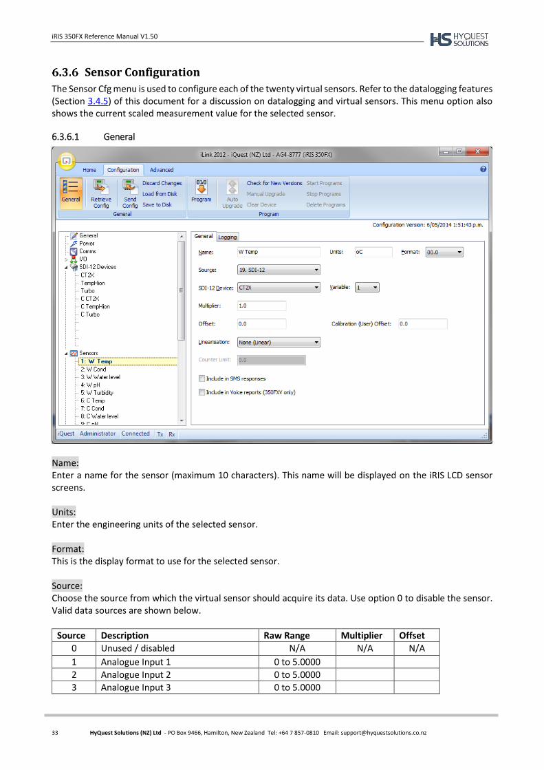
iRIS 350FX Reference Manual V1.50
33 HyQuest Solutions (NZ) Ltd - PO Box 9466, Hamilton, New Zealand Tel: +64 7 857-0810 Email: [email protected]
Sensor Configuration
The Sensor Cfg menu is used to configure each of the twenty virtual sensors. Refer to the datalogging features (Section 3.4.5) of this document for a discussion on datalogging and virtual sensors. This menu option also shows the current scaled measurement value for the selected sensor.
6.3.6.1 General
Name: Enter a name for the sensor (maximum 10 characters). This name will be displayed on the iRIS LCD sensor screens. Units: Enter the engineering units of the selected sensor. Format: This is the display format to use for the selected sensor. Source: Choose the source from which the virtual sensor should acquire its data. Use option 0 to disable the sensor. Valid data sources are shown below.
Source Description Raw Range Multiplier Offset
0 Unused / disabled N/A N/A N/A
1 Analogue Input 1 0 to 5.0000
2 Analogue Input 2 0 to 5.0000
3 Analogue Input 3 0 to 5.0000
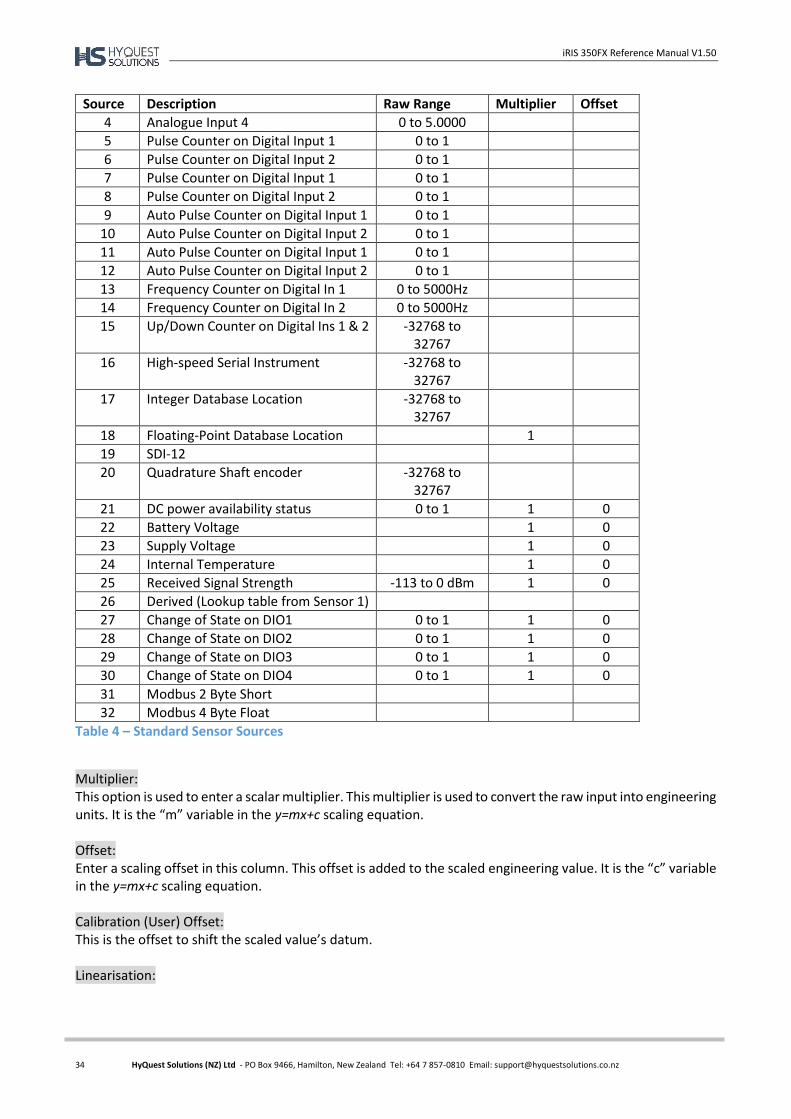
iRIS 350FX Reference Manual V1.50
34 HyQuest Solutions (NZ) Ltd - PO Box 9466, Hamilton, New Zealand Tel: +64 7 857-0810 Email: [email protected]
Source Description Raw Range Multiplier Offset
4 Analogue Input 4 0 to 5.0000
5 Pulse Counter on Digital Input 1 0 to 1
6 Pulse Counter on Digital Input 2 0 to 1
7 Pulse Counter on Digital Input 1 0 to 1
8 Pulse Counter on Digital Input 2 0 to 1
9 Auto Pulse Counter on Digital Input 1 0 to 1
10 Auto Pulse Counter on Digital Input 2 0 to 1
11 Auto Pulse Counter on Digital Input 1 0 to 1
12 Auto Pulse Counter on Digital Input 2 0 to 1
13 Frequency Counter on Digital In 1 0 to 5000Hz
14 Frequency Counter on Digital In 2 0 to 5000Hz
15 Up/Down Counter on Digital Ins 1 & 2 -32768 to 32767
16 High-speed Serial Instrument -32768 to 32767
17 Integer Database Location -32768 to 32767
18 Floating-Point Database Location 1
19 SDI-12
20 Quadrature Shaft encoder -32768 to 32767
21 DC power availability status 0 to 1 1 0
22 Battery Voltage 1 0
23 Supply Voltage 1 0
24 Internal Temperature 1 0
25 Received Signal Strength -113 to 0 dBm 1 0
26 Derived (Lookup table from Sensor 1)
27 Change of State on DIO1 0 to 1 1 0
28 Change of State on DIO2 0 to 1 1 0
29 Change of State on DIO3 0 to 1 1 0
30 Change of State on DIO4 0 to 1 1 0
31 Modbus 2 Byte Short
32 Modbus 4 Byte Float
Table 4 – Standard Sensor Sources
Multiplier: This option is used to enter a scalar multiplier. This multiplier is used to convert the raw input into engineering units. It is the “m” variable in the y=mx+c scaling equation. Offset: Enter a scaling offset in this column. This offset is added to the scaled engineering value. It is the “c” variable in the y=mx+c scaling equation. Calibration (User) Offset: This is the offset to shift the scaled value’s datum. Linearisation:
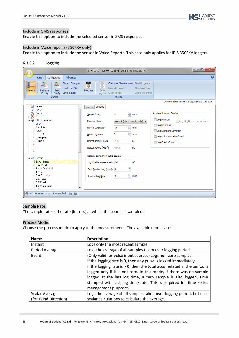
iRIS 350FX Reference Manual V1.50
35 HyQuest Solutions (NZ) Ltd - PO Box 9466, Hamilton, New Zealand Tel: +64 7 857-0810 Email: [email protected]
Include in SMS responses: Enable this option to include the selected sensor in SMS responses. Include in Voice reports (350FXV only): Enable this option to include the sensor in Voice Reports. This case only applies for iRIS 350FXV loggers.
6.3.6.2 Logging
Sample Rate: The sample rate is the rate (in secs) at which the source is sampled. Process Mode: Choose the process mode to apply to the measurements. The available modes are:
Name Description
Instant Logs only the most recent sample
Period Average Logs the average of all samples taken over logging period
Event (Only valid for pulse input sources) Logs non-zero samples. If the logging rate is 0, then any pulse is logged immediately. If the logging rate is > 0, then the total accumulated in the period is logged only if it is not zero. In this mode, if there was no sample logged at the last log time, a zero sample is also logged, time stamped with last log time/date. This is required for time series management purposes.
Scalar Average (for Wind Direction)
Logs the average of all samples taken over logging period, but uses scalar calculations to calculate the average.
iRIS 350FX Reference Manual V1.50
36 HyQuest Solutions (NZ) Ltd - PO Box 9466, Hamilton, New Zealand Tel: +64 7 857-0810 Email: [email protected]
Name Description
One Minute Average Logs the average of all samples taken over the last one minute period prior to the data being logged. This is useful for sensors that are powered on a timed basis using a digital output and some averaging is still required. In this case, using the Full Period Average would give an incorrect value.
Log Rate: This is the logging rate (in mins) when the sensor is not in alarm. If you wish to log digital data on change of state you can enter a value of 0. If this parameter is left at 0 for analogue sources, they will not be logged. The dc power change of state ignores this parameter, so it is typically set to zero for this source as well. Alarm Log Rate: This is the logging rate (in mins) when the sensor is in alarm. Reject Below (Low): This option is used to enter a simple rejection value. Any value equal to or below this will be ignored and the last “good” value retained. Reject Above (High): Any value equal to or above this will be ignored and the last “good” value retained. Log if delta exceeds +/-: This is the amount the latest processed value (in actual engineering units of the sensor) must differ from the last logged value in order to be logged. The delta logging (if enabled by having a non-zero set-point) is done at the time the logging would normally occur for the sensor as configured. All the delta decision does look at the last value that was actually logged and compare it to the newly processed sample value. If the difference is greater than the configured delta value, then the sample is actually logged. First Routine Log (hour): This is the hour in the day when the first routine log will occur. Routine Log Rate: The routine log rate is the interval at which a routine log is taken after the first hour is reached. Auxiliary Logging Control: You can also configure the extended datalogging options using the logging flags. The list of the available flags are given below.
1. Log Minimum value sampled in the log period.
2. Log Maximum value sampled in the log period.
3. Log Standard Deviation of samples in log period.
4. Log Calculated Flow Rate (in l/s) over log period or Log Accumulated Volume for sensors with an
analogue or frequency source.
5. Log Check Count.
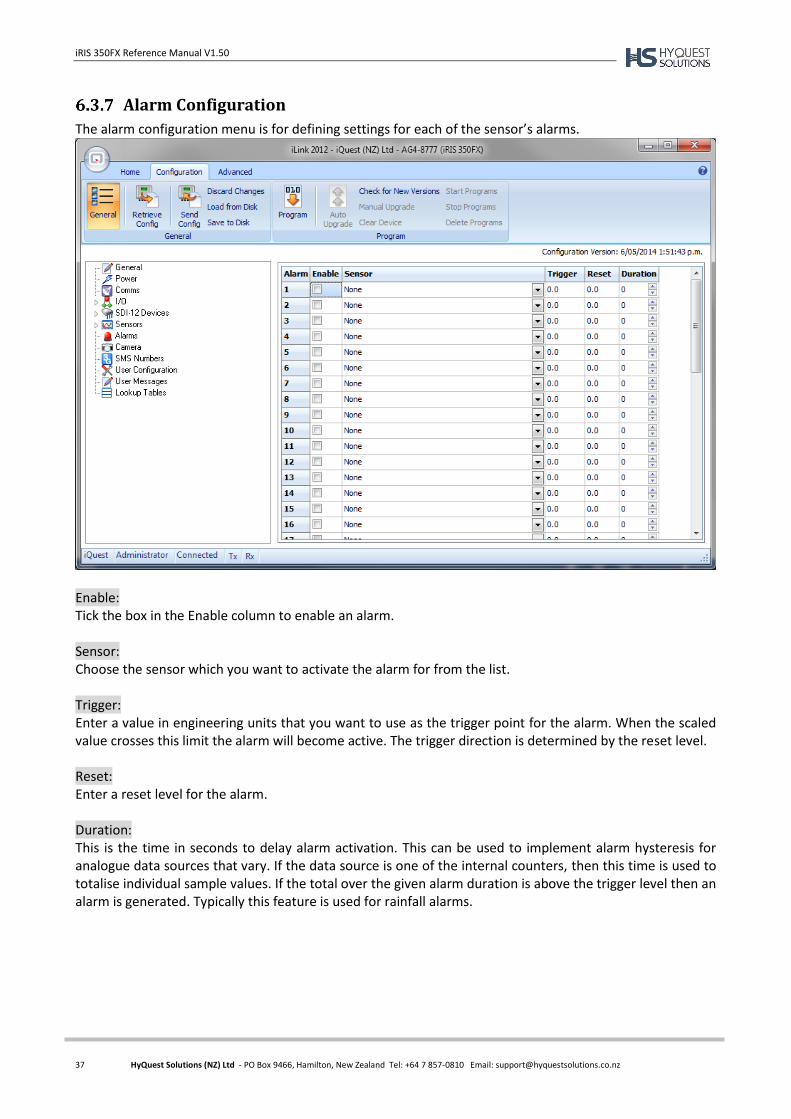
iRIS 350FX Reference Manual V1.50
37 HyQuest Solutions (NZ) Ltd - PO Box 9466, Hamilton, New Zealand Tel: +64 7 857-0810 Email: [email protected]
Alarm Configuration
The alarm configuration menu is for defining settings for each of the sensor’s alarms.
Enable: Tick the box in the Enable column to enable an alarm. Sensor: Choose the sensor which you want to activate the alarm for from the list. Trigger: Enter a value in engineering units that you want to use as the trigger point for the alarm. When the scaled value crosses this limit the alarm will become active. The trigger direction is determined by the reset level. Reset: Enter a reset level for the alarm. Duration: This is the time in seconds to delay alarm activation. This can be used to implement alarm hysteresis for analogue data sources that vary. If the data source is one of the internal counters, then this time is used to totalise individual sample values. If the total over the given alarm duration is above the trigger level then an alarm is generated. Typically this feature is used for rainfall alarms.
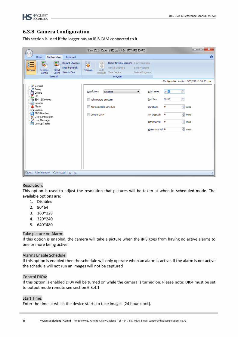
iRIS 350FX Reference Manual V1.50
38 HyQuest Solutions (NZ) Ltd - PO Box 9466, Hamilton, New Zealand Tel: +64 7 857-0810 Email: [email protected]
Camera Configuration
This section is used if the logger has an iRIS CAM connected to it.
Resolution: This option is used to adjust the resolution that pictures will be taken at when in scheduled mode. The available options are:
1. Disabled
2. 80*64
3. 160*128
4. 320*240
5. 640*480
Take picture on Alarm: If this option is enabled, the camera will take a picture when the iRIS goes from having no active alarms to one or more being active. Alarms Enable Schedule: If this option is enabled then the schedule will only operate when an alarm is active. If the alarm is not active the schedule will not run an images will not be captured Control DIO4: If this option is enabled DI04 will be turned on while the camera is turned on. Please note: DI04 must be set to output mode remote see section 6.3.4.1 Start Time: Enter the time at which the device starts to take images (24 hour clock).
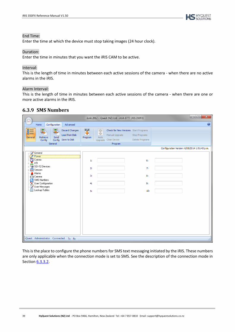
iRIS 350FX Reference Manual V1.50
39 HyQuest Solutions (NZ) Ltd - PO Box 9466, Hamilton, New Zealand Tel: +64 7 857-0810 Email: [email protected]
End Time: Enter the time at which the device must stop taking images (24 hour clock). Duration: Enter the time in minutes that you want the iRIS CAM to be active. Interval: This is the length of time in minutes between each active sessions of the camera - when there are no active alarms in the iRIS. Alarm Interval: This is the length of time in minutes between each active sessions of the camera - when there are one or more active alarms in the iRIS.
SMS Numbers
This is the place to configure the phone numbers for SMS text messaging initiated by the iRIS. These numbers are only applicable when the connection mode is set to SMS. See the description of the connection mode in Section 6.3.3.2.
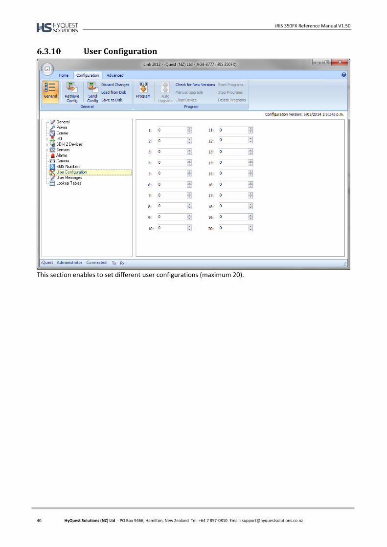
iRIS 350FX Reference Manual V1.50
40 HyQuest Solutions (NZ) Ltd - PO Box 9466, Hamilton, New Zealand Tel: +64 7 857-0810 Email: [email protected]
User Configuration
This section enables to set different user configurations (maximum 20).
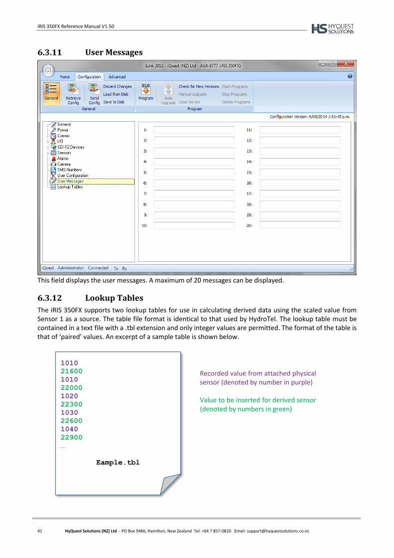
iRIS 350FX Reference Manual V1.50
41 HyQuest Solutions (NZ) Ltd - PO Box 9466, Hamilton, New Zealand Tel: +64 7 857-0810 Email: [email protected]
User Messages
This field displays the user messages. A maximum of 20 messages can be displayed.
Lookup Tables
The iRIS 350FX supports two lookup tables for use in calculating derived data using the scaled value from Sensor 1 as a source. The table file format is identical to that used by HydroTel. The lookup table must be contained in a text file with a .tbl extension and only integer values are permitted. The format of the table is that of ‘paired’ values. An excerpt of a sample table is shown below.
1010
21600
1010
22000
1020
22300
1030
22600
1040
22900
…
Eample.tbl
Recorded value from attached physical sensor (denoted by number in purple) Value to be inserted for derived sensor (denoted by numbers in green)
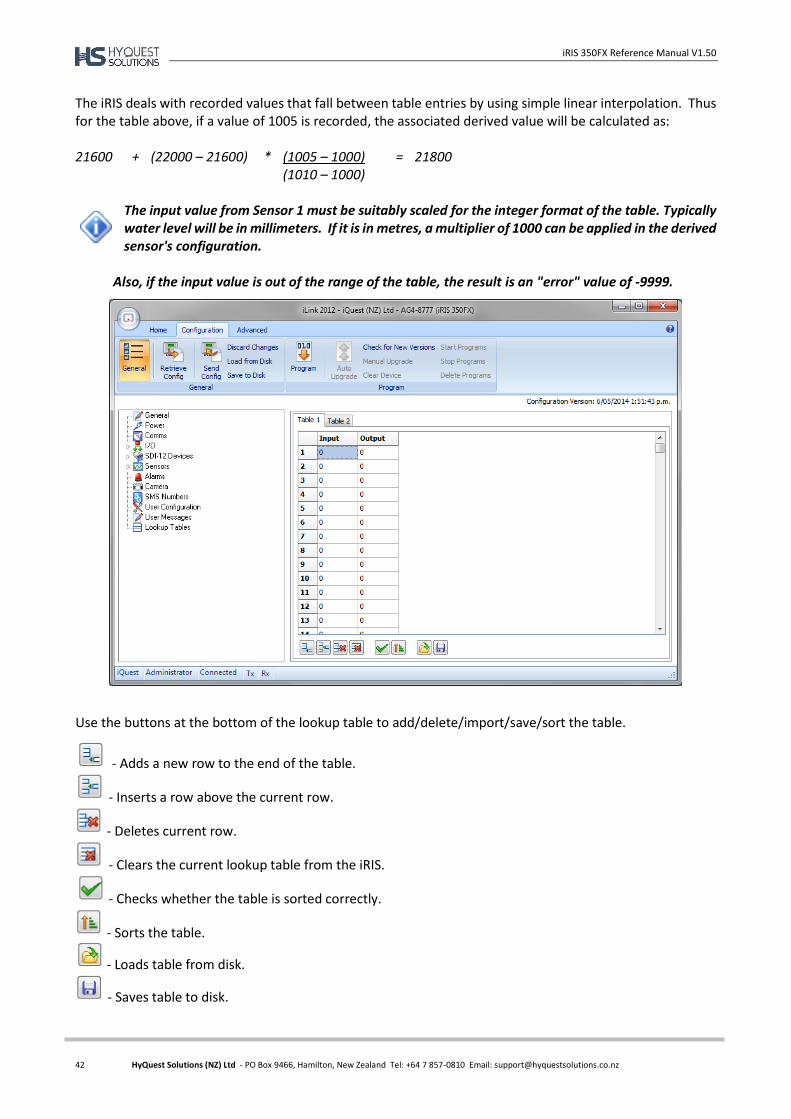
iRIS 350FX Reference Manual V1.50
42 HyQuest Solutions (NZ) Ltd - PO Box 9466, Hamilton, New Zealand Tel: +64 7 857-0810 Email: [email protected]
The iRIS deals with recorded values that fall between table entries by using simple linear interpolation. Thus for the table above, if a value of 1005 is recorded, the associated derived value will be calculated as: 21600 + (22000 – 21600) * (1005 – 1000) = 21800 (1010 – 1000)
The input value from Sensor 1 must be suitably scaled for the integer format of the table. Typically water level will be in millimeters. If it is in metres, a multiplier of 1000 can be applied in the derived sensor's configuration.
Also, if the input value is out of the range of the table, the result is an "error" value of -9999.
Use the buttons at the bottom of the lookup table to add/delete/import/save/sort the table.
- Adds a new row to the end of the table.
- Inserts a row above the current row.
- Deletes current row.
- Clears the current lookup table from the iRIS.
- Checks whether the table is sorted correctly.
- Sorts the table.
- Loads table from disk.
- Saves table to disk.
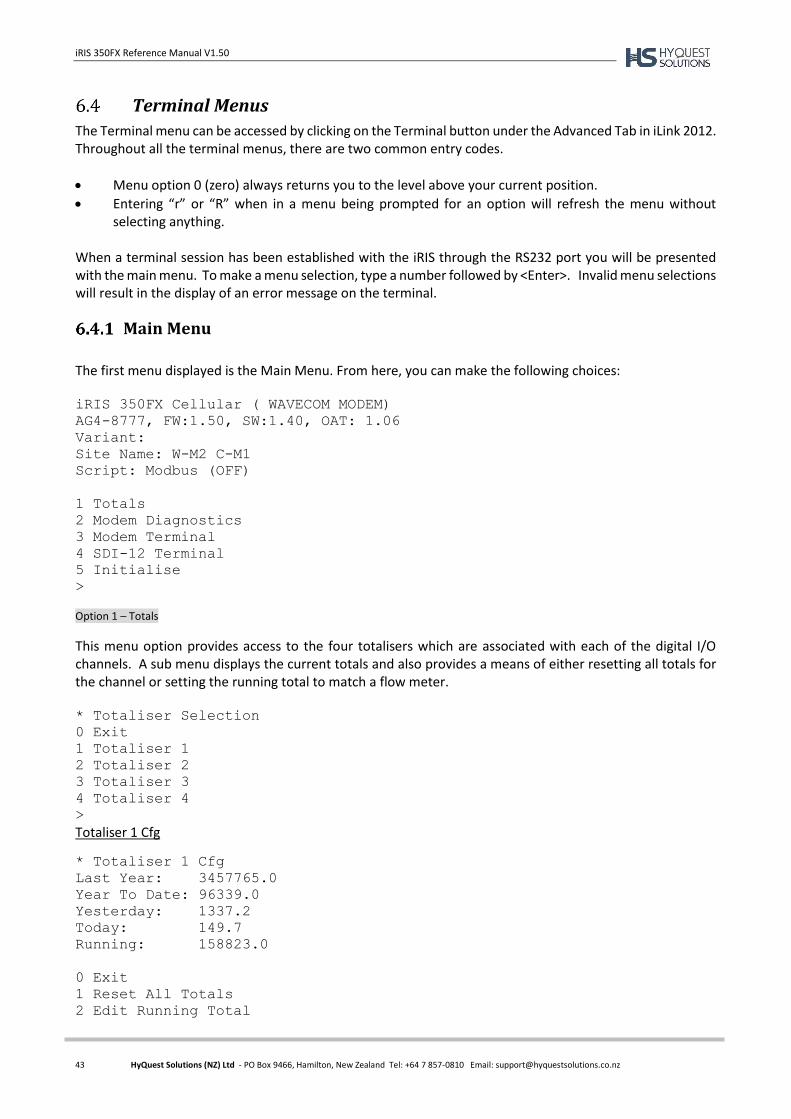
iRIS 350FX Reference Manual V1.50
43 HyQuest Solutions (NZ) Ltd - PO Box 9466, Hamilton, New Zealand Tel: +64 7 857-0810 Email: [email protected]
Terminal Menus
The Terminal menu can be accessed by clicking on the Terminal button under the Advanced Tab in iLink 2012. Throughout all the terminal menus, there are two common entry codes.
Menu option 0 (zero) always returns you to the level above your current position.
Entering “r” or “R” when in a menu being prompted for an option will refresh the menu without selecting anything.
When a terminal session has been established with the iRIS through the RS232 port you will be presented with the main menu. To make a menu selection, type a number followed by <Enter>. Invalid menu selections will result in the display of an error message on the terminal.
Main Menu
The first menu displayed is the Main Menu. From here, you can make the following choices:
iRIS 350FX Cellular ( WAVECOM MODEM)
AG4-8777, FW:1.50, SW:1.40, OAT: 1.06
Variant:
Site Name: W-M2 C-M1
Script: Modbus (OFF)
1 Totals
2 Modem Diagnostics
3 Modem Terminal
4 SDI-12 Terminal
5 Initialise
>
Option 1 – Totals
This menu option provides access to the four totalisers which are associated with each of the digital I/O channels. A sub menu displays the current totals and also provides a means of either resetting all totals for the channel or setting the running total to match a flow meter. * Totaliser Selection
0 Exit
1 Totaliser 1
2 Totaliser 2
3 Totaliser 3
4 Totaliser 4
>
Totaliser 1 Cfg
* Totaliser 1 Cfg
Last Year: 3457765.0
Year To Date: 96339.0
Yesterday: 1337.2
Today: 149.7
Running: 158823.0
0 Exit
1 Reset All Totals
2 Edit Running Total
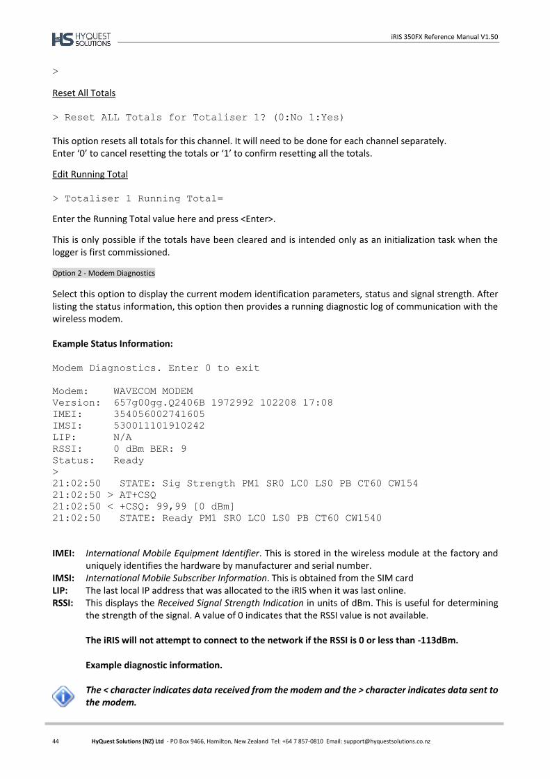
iRIS 350FX Reference Manual V1.50
44 HyQuest Solutions (NZ) Ltd - PO Box 9466, Hamilton, New Zealand Tel: +64 7 857-0810 Email: [email protected]
>
Reset All Totals > Reset ALL Totals for Totaliser 1? (0:No 1:Yes)
This option resets all totals for this channel. It will need to be done for each channel separately. Enter ‘0’ to cancel resetting the totals or ‘1’ to confirm resetting all the totals.
Edit Running Total > Totaliser 1 Running Total=
Enter the Running Total value here and press <Enter>.
This is only possible if the totals have been cleared and is intended only as an initialization task when the logger is first commissioned. Option 2 - Modem Diagnostics
Select this option to display the current modem identification parameters, status and signal strength. After listing the status information, this option then provides a running diagnostic log of communication with the wireless modem. Example Status Information: Modem Diagnostics. Enter 0 to exit
Modem: WAVECOM MODEM
Version: 657g00gg.Q2406B 1972992 102208 17:08
IMEI: 354056002741605
IMSI: 530011101910242
LIP: N/A
RSSI: 0 dBm BER: 9
Status: Ready
>
21:02:50 STATE: Sig Strength PM1 SR0 LC0 LS0 PB CT60 CW154
21:02:50 > AT+CSQ
21:02:50 < +CSQ: 99,99 [0 dBm]
21:02:50 STATE: Ready PM1 SR0 LC0 LS0 PB CT60 CW1540
IMEI: International Mobile Equipment Identifier. This is stored in the wireless module at the factory and uniquely identifies the hardware by manufacturer and serial number.
IMSI: International Mobile Subscriber Information. This is obtained from the SIM card LIP: The last local IP address that was allocated to the iRIS when it was last online. RSSI: This displays the Received Signal Strength Indication in units of dBm. This is useful for determining
the strength of the signal. A value of 0 indicates that the RSSI value is not available.
The iRIS will not attempt to connect to the network if the RSSI is 0 or less than -113dBm. Example diagnostic information.
The < character indicates data received from the modem and the > character indicates data sent to the modem.
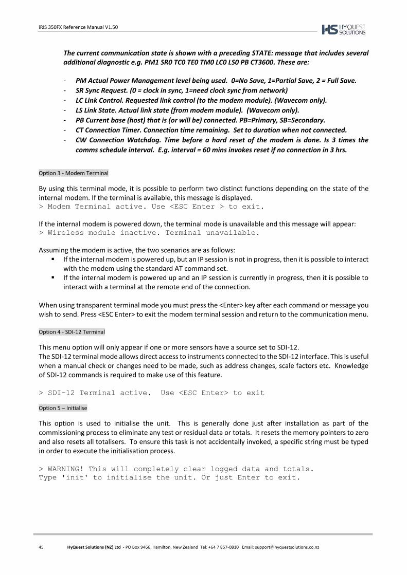
iRIS 350FX Reference Manual V1.50
45 HyQuest Solutions (NZ) Ltd - PO Box 9466, Hamilton, New Zealand Tel: +64 7 857-0810 Email: [email protected]
The current communication state is shown with a preceding STATE: message that includes several additional diagnostic e.g. PM1 SR0 TC0 TE0 TM0 LC0 LS0 PB CT3600. These are: - PM Actual Power Management level being used. 0=No Save, 1=Partial Save, 2 = Full Save.
- SR Sync Request. (0 = clock in sync, 1=need clock sync from network)
- LC Link Control. Requested link control (to the modem module). (Wavecom only).
- LS Link State. Actual link state (from modem module). (Wavecom only).
- PB Current base (host) that is (or will be) connected. PB=Primary, SB=Secondary.
- CT Connection Timer. Connection time remaining. Set to duration when not connected.
- CW Connection Watchdog. Time before a hard reset of the modem is done. Is 3 times the
comms schedule interval. E.g. interval = 60 mins invokes reset if no connection in 3 hrs.
Option 3 - Modem Terminal
By using this terminal mode, it is possible to perform two distinct functions depending on the state of the internal modem. If the terminal is available, this message is displayed. > Modem Terminal active. Use <ESC Enter > to exit.
If the internal modem is powered down, the terminal mode is unavailable and this message will appear: > Wireless module inactive. Terminal unavailable.
Assuming the modem is active, the two scenarios are as follows: If the internal modem is powered up, but an IP session is not in progress, then it is possible to interact
with the modem using the standard AT command set. If the internal modem is powered up and an IP session is currently in progress, then it is possible to
interact with a terminal at the remote end of the connection.
When using transparent terminal mode you must press the <Enter> key after each command or message you wish to send. Press <ESC Enter> to exit the modem terminal session and return to the communication menu. Option 4 - SDI-12 Terminal
This menu option will only appear if one or more sensors have a source set to SDI-12. The SDI-12 terminal mode allows direct access to instruments connected to the SDI-12 interface. This is useful when a manual check or changes need to be made, such as address changes, scale factors etc. Knowledge of SDI-12 commands is required to make use of this feature. > SDI-12 Terminal active. Use <ESC Enter> to exit
Option 5 – Initialise
This option is used to initialise the unit. This is generally done just after installation as part of the commissioning process to eliminate any test or residual data or totals. It resets the memory pointers to zero and also resets all totalisers. To ensure this task is not accidentally invoked, a specific string must be typed in order to execute the initialisation process. > WARNING! This will completely clear logged data and totals.
Type 'init' to initialise the unit. Or just Enter to exit.

iRIS 350FX Reference Manual V1.50
46 HyQuest Solutions (NZ) Ltd - PO Box 9466, Hamilton, New Zealand Tel: +64 7 857-0810 Email: [email protected]
7 Operation
LED Indicators
The iRIS has several LED indicators. The main status LED and eight diagnostic LEDs are visible from the front of the enclosure.
Status LED
The status LED is a tri-colour device that is used to indicate the unit status.
Status LED Indication
Idle, low or no signal strength Flashes red once every three seconds
Idle, adequate signal strength Flashes green once every three seconds
Connecting to network Flashes blue every half a second
Connected to network Flashes blue once every three seconds
Failed to connect Flashes red every half a second
Table 5 - Status LED Indication Modes
Diagnostic LEDs
The iRIS has eight LED indicators that are useful for diagnostic purposes. These are visible through the front of the enclosure.
With the exception of the SDI-12 TX LED, these indicators are only active when the power management mode is set to No Power Save (see the Features Section 3.4.4 for details on power management).
DIO1 Illuminated red when Digital I/O #1 is active. DIO2 Illuminated red when Digital I/O #2 is active. DIO3 Illuminated red when Digital I/O #3 is active. DIO4 Illuminated red when Digital I/O #4 is active. RS232 RX Flashes green when data is received from the RS232 port. RS232 TX Flashes green when data is transmitted out the RS232 port. Modem Flashes green when there is receive or transmit activity to/from the modem. SDI-12 Flashes green when an SDI-12 message is transmitted or received.
LCD & Keypad
LCD Operation
The iRIS LCD is controlled to optimise power consumption. If the display has powered down (in full power save mode), the unit is in the lowest power mode and can be woken by pressing any key on the keypad. After a certain period of no key presses, the display and backlight will power down again, although other functions continue normally. If the user was logged on (PIN entered), they will be logged off. This version of software has the timeout period set to 5 minutes.
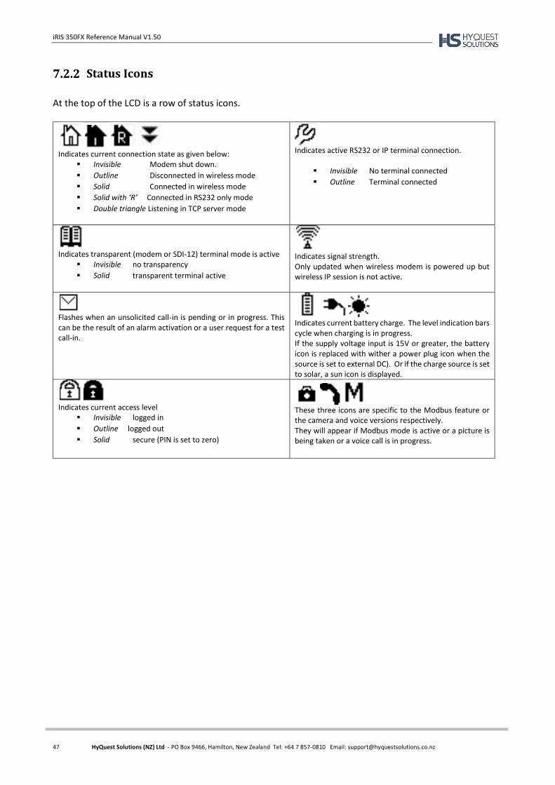
iRIS 350FX Reference Manual V1.50
47 HyQuest Solutions (NZ) Ltd - PO Box 9466, Hamilton, New Zealand Tel: +64 7 857-0810 Email: [email protected]
Status Icons
At the top of the LCD is a row of status icons.
Indicates current connection state as given below:
Invisible Modem shut down.
Outline Disconnected in wireless mode
Solid Connected in wireless mode
Solid with ‘R’ Connected in RS232 only mode
Double triangle Listening in TCP server mode
Indicates active RS232 or IP terminal connection.
Invisible No terminal connected
Outline Terminal connected
Indicates transparent (modem or SDI-12) terminal mode is active
Invisible no transparency
Solid transparent terminal active
Indicates signal strength. Only updated when wireless modem is powered up but wireless IP session is not active.
Flashes when an unsolicited call-in is pending or in progress. This can be the result of an alarm activation or a user request for a test call-in.
Indicates current battery charge. The level indication bars cycle when charging is in progress. If the supply voltage input is 15V or greater, the battery icon is replaced with wither a power plug icon when the source is set to external DC). Or if the charge source is set to solar, a sun icon is displayed.
Indicates current access level
Invisible logged in
Outline logged out
Solid secure (PIN is set to zero)
These three icons are specific to the Modbus feature or the camera and voice versions respectively. They will appear if Modbus mode is active or a picture is being taken or a voice call is in progress.
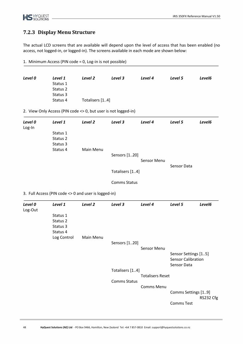
iRIS 350FX Reference Manual V1.50
48 HyQuest Solutions (NZ) Ltd - PO Box 9466, Hamilton, New Zealand Tel: +64 7 857-0810 Email: [email protected]
Display Menu Structure
The actual LCD screens that are available will depend upon the level of access that has been enabled (no access, not logged-in, or logged-in). The screens available in each mode are shown below: 1. Minimum Access (PIN code = 0, Log-in is not possible)
Level 0 Level 1 Level 2 Level 3 Level 4 Level 5 Level6
Status 1 Status 2 Status 3 Status 4 Totalisers [1..4]
2. View Only Access (PIN code <> 0, but user is not logged-in)
Level 0 Level 1 Level 2 Level 3 Level 4 Level 5 Level6 Log-In
Status 1 Status 2 Status 3 Status 4 Main Menu
Sensors [1..20] Sensor Menu
Sensor Data Totalisers [1..4]
Comms Status
3. Full Access (PIN code <> 0 and user is logged-in)
Level 0 Level 1 Level 2 Level 3 Level 4 Level 5 Level6 Log-Out
Status 1 Status 2 Status 3 Status 4 Log Control Main Menu
Sensors [1..20] Sensor Menu Sensor Settings [1..5]
Sensor Calibration Sensor Data
Totalisers [1..4] Totalisers Reset
Comms Status Comms Menu Comms Settings [1..9] RS232 Cfg Comms Test
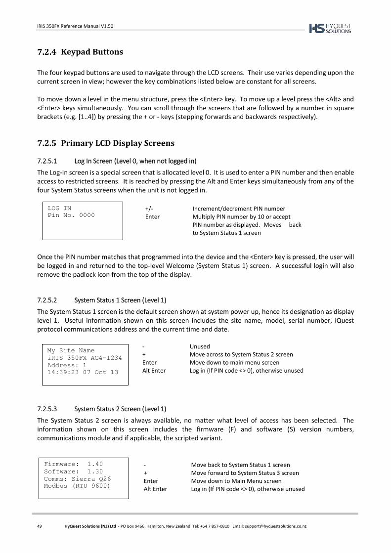
iRIS 350FX Reference Manual V1.50
49 HyQuest Solutions (NZ) Ltd - PO Box 9466, Hamilton, New Zealand Tel: +64 7 857-0810 Email: [email protected]
Keypad Buttons
The four keypad buttons are used to navigate through the LCD screens. Their use varies depending upon the current screen in view; however the key combinations listed below are constant for all screens. To move down a level in the menu structure, press the <Enter> key. To move up a level press the <Alt> and <Enter> keys simultaneously. You can scroll through the screens that are followed by a number in square brackets (e.g. [1..4]) by pressing the + or - keys (stepping forwards and backwards respectively).
Primary LCD Display Screens
7.2.5.1 Log In Screen (Level 0, when not logged in)
The Log-In screen is a special screen that is allocated level 0. It is used to enter a PIN number and then enable access to restricted screens. It is reached by pressing the Alt and Enter keys simultaneously from any of the four System Status screens when the unit is not logged in.
Once the PIN number matches that programmed into the device and the <Enter> key is pressed, the user will be logged in and returned to the top-level Welcome (System Status 1) screen. A successful login will also remove the padlock icon from the top of the display.
7.2.5.2 System Status 1 Screen (Level 1)
The System Status 1 screen is the default screen shown at system power up, hence its designation as display level 1. Useful information shown on this screen includes the site name, model, serial number, iQuest protocol communications address and the current time and date.
7.2.5.3 System Status 2 Screen (Level 1)
The System Status 2 screen is always available, no matter what level of access has been selected. The information shown on this screen includes the firmware (F) and software (S) version numbers, communications module and if applicable, the scripted variant.
My Site Name
iRIS 350FX AG4-1234
Address: 1
14:39:23 07 Oct 13
- Unused + Move across to System Status 2 screen Enter Move down to main menu screen Alt Enter Log in (If PIN code <> 0), otherwise unused
LOG IN
Pin No. 0000 +/- Increment/decrement PIN number Enter Multiply PIN number by 10 or accept
PIN number as displayed. Moves back to System Status 1 screen
Firmware: 1.40
Software: 1.30
Comms: Sierra Q26
Modbus (RTU 9600)
- Move back to System Status 1 screen + Move forward to System Status 3 screen Enter Move down to Main Menu screen Alt Enter Log in (If PIN code <> 0), otherwise unused
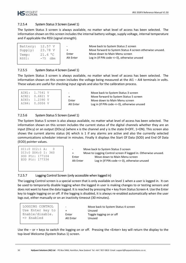
iRIS 350FX Reference Manual V1.50
50 HyQuest Solutions (NZ) Ltd - PO Box 9466, Hamilton, New Zealand Tel: +64 7 857-0810 Email: [email protected]
7.2.5.4 System Status 3 Screen (Level 1)
The System Status 3 screen is always available, no matter what level of access has been selected. The information shown on this screen includes the internal battery voltage, supply voltage, internal temperature and if applicable the RSSI (signal strength).
7.2.5.5 System Status 4 Screen (Level 1)
The System Status 3 screen is always available, no matter what level of access has been selected. The information shown on this screen includes the voltage being measured at the AI1 – AI4 terminals in volts. These values are useful for checking input signals and also for the calibration process.
7.2.5.6 System Status 5 Screen (Level 1)
The System Status 5 screen is also always available, no matter what level of access has been selected. The information shown on this screen includes the current status of the digital channels whether they are an input (DIx:y) or an output (DOx:y) (where x is the channel and y is the state 0=OFF, 1=ON). This screen also shows the current alarms status (A) which is 1 if any alarms are active and also the currently selected communications scheduler interval in minutes. Finally it displays the Start Of Data (SOD) and End Of Data (EOD) pointer values.
7.2.5.7 Logging Control Screen (only accessible when logged in)
The Logging Control screen is a special screen that is only available on level 1 when a user is logged in. It can be used to temporarily disable logging when the logged in user is making changes to or testing sensors and does not want to have the data logged. It is reached by pressing the + key from Status Screen 4. Use the Enter key to toggle logging on or off. If the logging is disabled, it is always re-enabled automatically when the user logs out, either manually or on an inactivity timeout (30 minutes).
Use the – or + keys to switch the logging on or off. Pressing the <Enter> key will return the display to the top-level Welcome (System Status 1) screen.
Battery: 12.57 V
Supply: 23.78 V
Temp: 21.6 C RSSI: -75 dBm
- Move back to System Status 2 screen + Move forward to System Status 4 screen otherwise unused. Enter Move down to Main Menu screen Alt Enter Log in (If PIN code <> 0), otherwise unused
DI1:0 DI2:1 A: 0
DI3:0 DO4:0 I: 360
SOD Ptr: 177104
EOD Ptr: 177336
- Move back to System Status 3 screen + Move to Logging Control screen if logged in. Otherwise unused. Enter Move down to Main Menu screen Alt Enter Log in (If PIN code <> 0), otherwise unused
LOGGING CONTROL
Use Enter key to
Enable/disable.
=> Enabled
- Move back to System Status 4 screen + Unused Enter Toggle logging on or off Alt Enter Unused
AIN1: 1.7541 V
AIN2: 0.6821 V
AIN3: 1.2390 V
AIN4: 0.0006 V
- Move back to System Status 3 screen + Move forward to System Status 5 screen Enter Move down to Main Menu screen Alt Enter Log in (If PIN code <> 0), otherwise unused
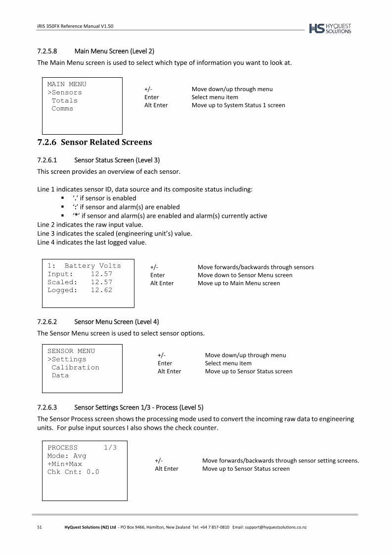
iRIS 350FX Reference Manual V1.50
51 HyQuest Solutions (NZ) Ltd - PO Box 9466, Hamilton, New Zealand Tel: +64 7 857-0810 Email: [email protected]
7.2.5.8 Main Menu Screen (Level 2)
The Main Menu screen is used to select which type of information you want to look at.
Sensor Related Screens
7.2.6.1 Sensor Status Screen (Level 3)
This screen provides an overview of each sensor. Line 1 indicates sensor ID, data source and its composite status including:
‘.’ if sensor is enabled ‘:’ if sensor and alarm(s) are enabled ‘*’ if sensor and alarm(s) are enabled and alarm(s) currently active
Line 2 indicates the raw input value. Line 3 indicates the scaled (engineering unit’s) value. Line 4 indicates the last logged value.
7.2.6.2 Sensor Menu Screen (Level 4)
The Sensor Menu screen is used to select sensor options.
7.2.6.3 Sensor Settings Screen 1/3 - Process (Level 5)
The Sensor Process screen shows the processing mode used to convert the incoming raw data to engineering units. For pulse input sources I also shows the check counter.
MAIN MENU
>Sensors
Totals
Comms
1: Battery Volts
Input: 12.57
Scaled: 12.57
Logged: 12.62
SENSOR MENU
>Settings
Calibration
Data
+/- Move down/up through menu Enter Select menu item Alt Enter Move up to System Status 1 screen
+/- Move forwards/backwards through sensors Enter Move down to Sensor Menu screen Alt Enter Move up to Main Menu screen
+/- Move down/up through menu Enter Select menu item Alt Enter Move up to Sensor Status screen
PROCESS 1/3
Mode: Avg
+Min+Max
Chk Cnt: 0.0
+/- Move forwards/backwards through sensor setting screens. Alt Enter Move up to Sensor Status screen
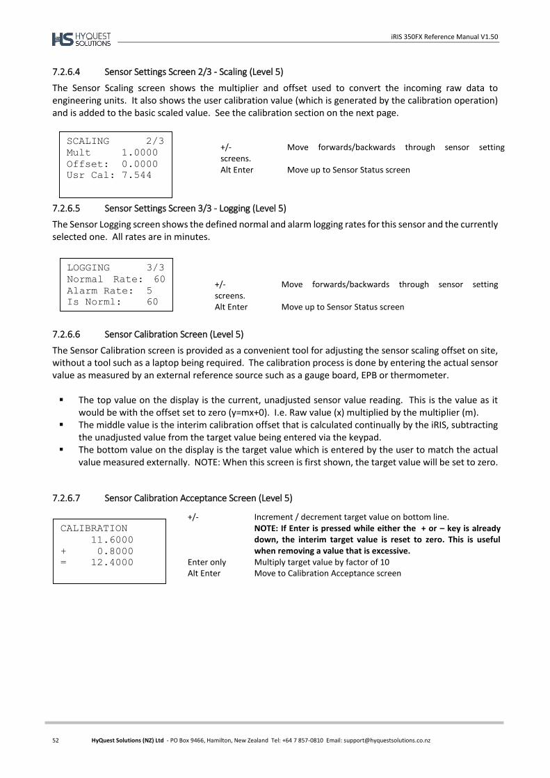
iRIS 350FX Reference Manual V1.50
52 HyQuest Solutions (NZ) Ltd - PO Box 9466, Hamilton, New Zealand Tel: +64 7 857-0810 Email: [email protected]
7.2.6.4 Sensor Settings Screen 2/3 - Scaling (Level 5)
The Sensor Scaling screen shows the multiplier and offset used to convert the incoming raw data to engineering units. It also shows the user calibration value (which is generated by the calibration operation) and is added to the basic scaled value. See the calibration section on the next page.
7.2.6.5 Sensor Settings Screen 3/3 - Logging (Level 5)
The Sensor Logging screen shows the defined normal and alarm logging rates for this sensor and the currently selected one. All rates are in minutes.
7.2.6.6 Sensor Calibration Screen (Level 5)
The Sensor Calibration screen is provided as a convenient tool for adjusting the sensor scaling offset on site, without a tool such as a laptop being required. The calibration process is done by entering the actual sensor value as measured by an external reference source such as a gauge board, EPB or thermometer. The top value on the display is the current, unadjusted sensor value reading. This is the value as it
would be with the offset set to zero (y=mx+0). I.e. Raw value (x) multiplied by the multiplier (m). The middle value is the interim calibration offset that is calculated continually by the iRIS, subtracting
the unadjusted value from the target value being entered via the keypad. The bottom value on the display is the target value which is entered by the user to match the actual
value measured externally. NOTE: When this screen is first shown, the target value will be set to zero.
7.2.6.7 Sensor Calibration Acceptance Screen (Level 5)
SCALING 2/3
Mult 1.0000
Offset: 0.0000
Usr Cal: 7.544
LOGGING 3/3
Normal Rate: 60
Alarm Rate: 5
Is Norml: 60
+/- Move forwards/backwards through sensor setting screens. Alt Enter Move up to Sensor Status screen
+/- Move forwards/backwards through sensor setting screens. Alt Enter Move up to Sensor Status screen
CALIBRATION
11.6000
+ 0.8000
= 12.4000
+/- Increment / decrement target value on bottom line. NOTE: If Enter is pressed while either the + or – key is already down, the interim target value is reset to zero. This is useful when removing a value that is excessive.
Enter only Multiply target value by factor of 10 Alt Enter Move to Calibration Acceptance screen
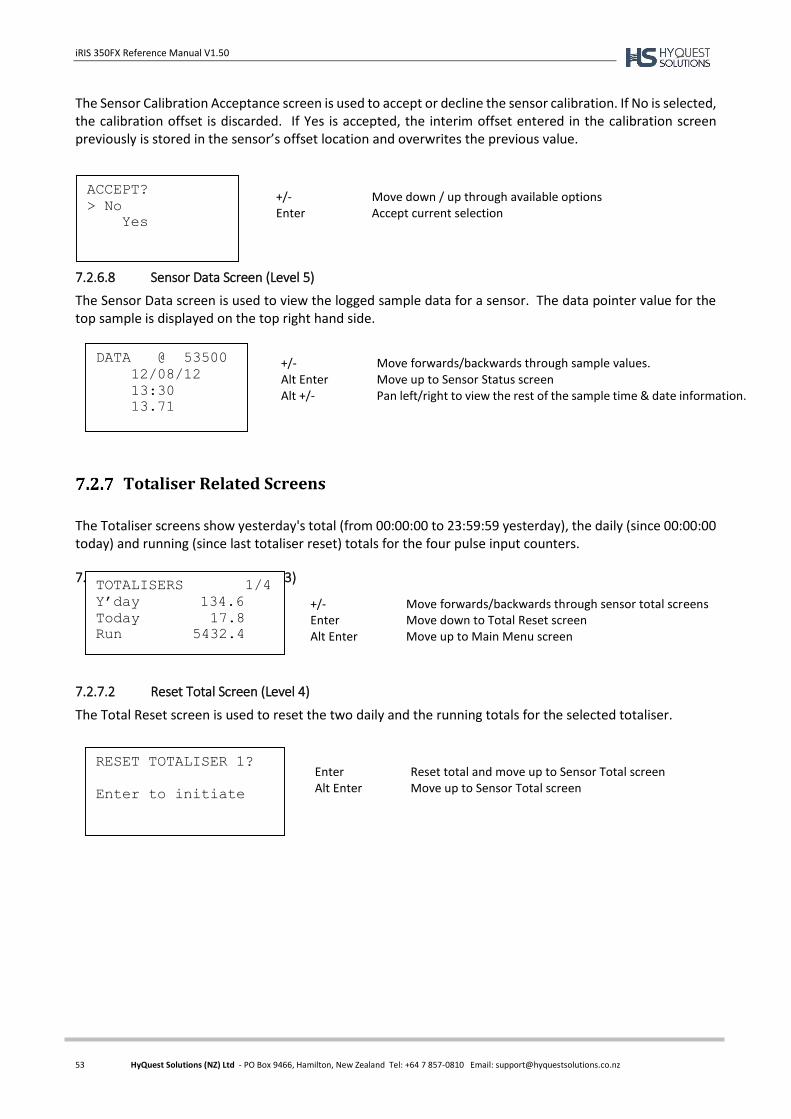
iRIS 350FX Reference Manual V1.50
53 HyQuest Solutions (NZ) Ltd - PO Box 9466, Hamilton, New Zealand Tel: +64 7 857-0810 Email: [email protected]
The Sensor Calibration Acceptance screen is used to accept or decline the sensor calibration. If No is selected, the calibration offset is discarded. If Yes is accepted, the interim offset entered in the calibration screen previously is stored in the sensor’s offset location and overwrites the previous value.
7.2.6.8 Sensor Data Screen (Level 5)
The Sensor Data screen is used to view the logged sample data for a sensor. The data pointer value for the top sample is displayed on the top right hand side.
Totaliser Related Screens
The Totaliser screens show yesterday's total (from 00:00:00 to 23:59:59 yesterday), the daily (since 00:00:00 today) and running (since last totaliser reset) totals for the four pulse input counters.
7.2.7.1 Total Screen x/4 (Level 3)
7.2.7.2 Reset Total Screen (Level 4)
The Total Reset screen is used to reset the two daily and the running totals for the selected totaliser.
DATA @ 53500
12/08/12
13:30
13.71
TOTALISERS 1/4
Y’day 134.6
Today 17.8
Run 5432.4
RESET TOTALISER 1?
Enter to initiate
+/- Move forwards/backwards through sample values. Alt Enter Move up to Sensor Status screen Alt +/- Pan left/right to view the rest of the sample time & date information.
+/- Move forwards/backwards through sensor total screens Enter Move down to Total Reset screen Alt Enter Move up to Main Menu screen
Enter Reset total and move up to Sensor Total screen Alt Enter Move up to Sensor Total screen
ACCEPT?
> No
Yes
+/- Move down / up through available options Enter Accept current selection
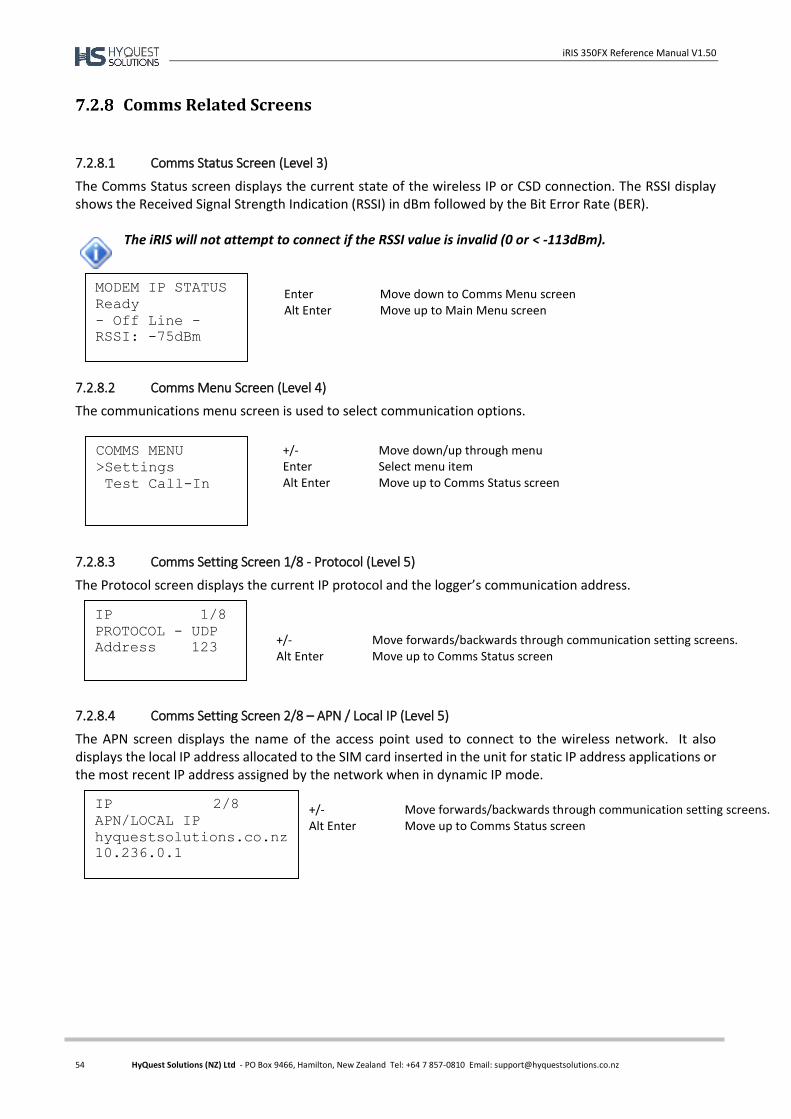
iRIS 350FX Reference Manual V1.50
54 HyQuest Solutions (NZ) Ltd - PO Box 9466, Hamilton, New Zealand Tel: +64 7 857-0810 Email: [email protected]
Comms Related Screens
7.2.8.1 Comms Status Screen (Level 3)
The Comms Status screen displays the current state of the wireless IP or CSD connection. The RSSI display shows the Received Signal Strength Indication (RSSI) in dBm followed by the Bit Error Rate (BER).
The iRIS will not attempt to connect if the RSSI value is invalid (0 or < -113dBm).
7.2.8.2 Comms Menu Screen (Level 4)
The communications menu screen is used to select communication options.
7.2.8.3 Comms Setting Screen 1/8 - Protocol (Level 5)
The Protocol screen displays the current IP protocol and the logger’s communication address.
7.2.8.4 Comms Setting Screen 2/8 – APN / Local IP (Level 5)
The APN screen displays the name of the access point used to connect to the wireless network. It also displays the local IP address allocated to the SIM card inserted in the unit for static IP address applications or the most recent IP address assigned by the network when in dynamic IP mode.
MODEM IP STATUS
Ready
- Off Line -
RSSI: -75dBm
COMMS MENU
>Settings
Test Call-In
IP 1/8
PROTOCOL - UDP
Address 123
IP 2/8
APN/LOCAL IP
hyquestsolutions.co.nz
10.236.0.1
Enter Move down to Comms Menu screen Alt Enter Move up to Main Menu screen
+/- Move down/up through menu Enter Select menu item Alt Enter Move up to Comms Status screen
+/- Move forwards/backwards through communication setting screens. Alt Enter Move up to Comms Status screen
+/- Move forwards/backwards through communication setting screens. Alt Enter Move up to Comms Status screen
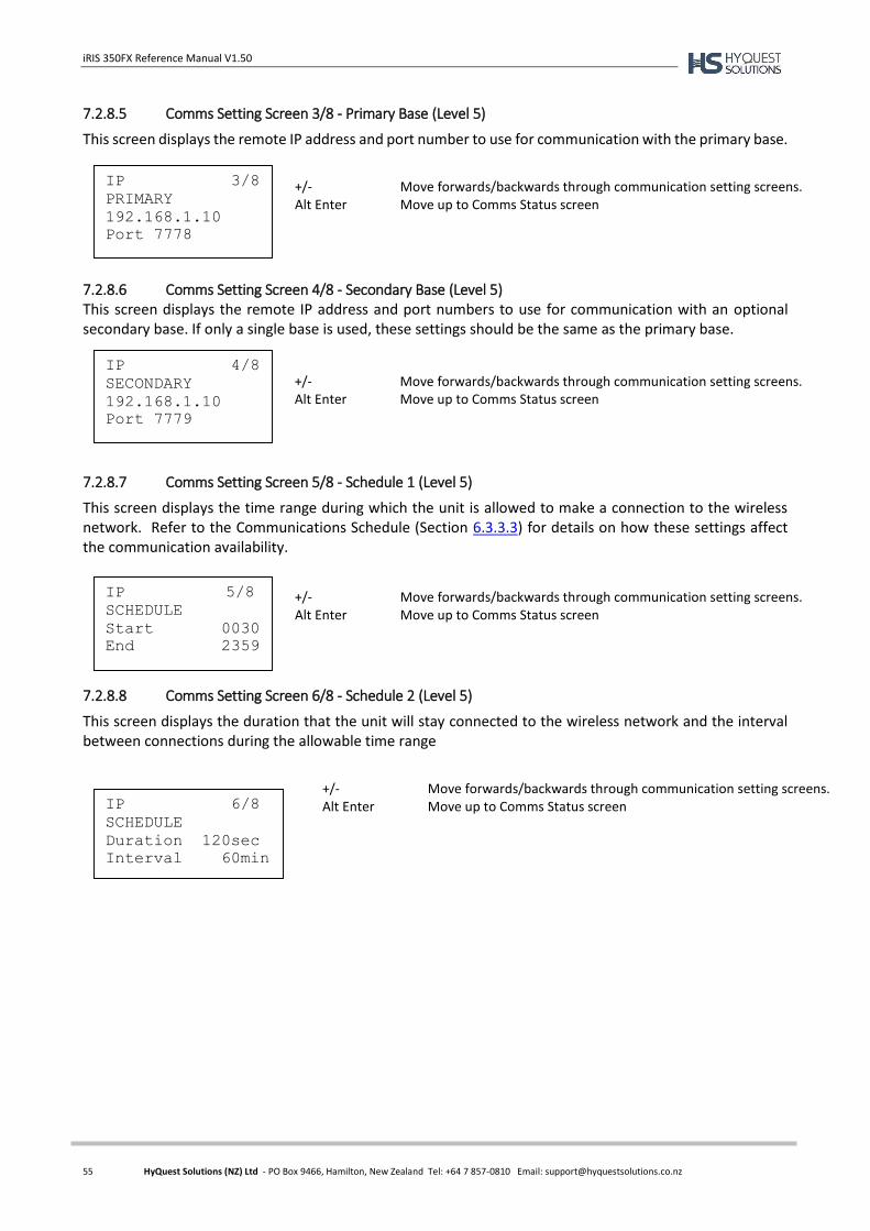
iRIS 350FX Reference Manual V1.50
55 HyQuest Solutions (NZ) Ltd - PO Box 9466, Hamilton, New Zealand Tel: +64 7 857-0810 Email: [email protected]
7.2.8.5 Comms Setting Screen 3/8 - Primary Base (Level 5)
This screen displays the remote IP address and port number to use for communication with the primary base.
7.2.8.6 Comms Setting Screen 4/8 - Secondary Base (Level 5) This screen displays the remote IP address and port numbers to use for communication with an optional secondary base. If only a single base is used, these settings should be the same as the primary base.
7.2.8.7 Comms Setting Screen 5/8 - Schedule 1 (Level 5)
This screen displays the time range during which the unit is allowed to make a connection to the wireless network. Refer to the Communications Schedule (Section 6.3.3.3) for details on how these settings affect the communication availability.
7.2.8.8 Comms Setting Screen 6/8 - Schedule 2 (Level 5)
This screen displays the duration that the unit will stay connected to the wireless network and the interval between connections during the allowable time range
IP 3/8
PRIMARY
192.168.1.10
Port 7778
IP 4/8
SECONDARY
192.168.1.10
Port 7779
IP 5/8
SCHEDULE
Start 0030
End 2359
IP 6/8
SCHEDULE
Duration 120sec
Interval 60min
+/- Move forwards/backwards through communication setting screens. Alt Enter Move up to Comms Status screen
+/- Move forwards/backwards through communication setting screens. Alt Enter Move up to Comms Status screen
+/- Move forwards/backwards through communication setting screens. Alt Enter Move up to Comms Status screen
+/- Move forwards/backwards through communication setting screens. Alt Enter Move up to Comms Status screen
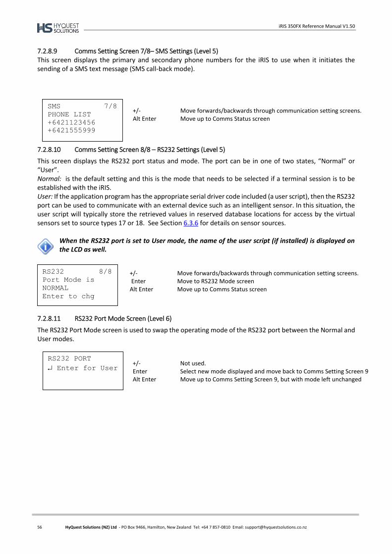
iRIS 350FX Reference Manual V1.50
56 HyQuest Solutions (NZ) Ltd - PO Box 9466, Hamilton, New Zealand Tel: +64 7 857-0810 Email: [email protected]
7.2.8.9 Comms Setting Screen 7/8– SMS Settings (Level 5) This screen displays the primary and secondary phone numbers for the iRIS to use when it initiates the sending of a SMS text message (SMS call-back mode).
7.2.8.10 Comms Setting Screen 8/8 – RS232 Settings (Level 5)
This screen displays the RS232 port status and mode. The port can be in one of two states, “Normal” or “User”. Normal: is the default setting and this is the mode that needs to be selected if a terminal session is to be established with the iRIS. User: If the application program has the appropriate serial driver code included (a user script), then the RS232 port can be used to communicate with an external device such as an intelligent sensor. In this situation, the user script will typically store the retrieved values in reserved database locations for access by the virtual sensors set to source types 17 or 18. See Section 6.3.6 for details on sensor sources.
When the RS232 port is set to User mode, the name of the user script (if installed) is displayed on the LCD as well.
7.2.8.11 RS232 Port Mode Screen (Level 6)
The RS232 Port Mode screen is used to swap the operating mode of the RS232 port between the Normal and User modes.
SMS 7/8
PHONE LIST
+6421123456
+6421555999
+/- Move forwards/backwards through communication setting screens. Alt Enter Move up to Comms Status screen
RS232 8/8
Port Mode is
NORMAL
Enter to chg
+/- Move forwards/backwards through communication setting screens. Enter Move to RS232 Mode screen Alt Enter Move up to Comms Status screen
RS232 PORT
Enter for User
+/- Not used. Enter Select new mode displayed and move back to Comms Setting Screen 9 Alt Enter Move up to Comms Setting Screen 9, but with mode left unchanged
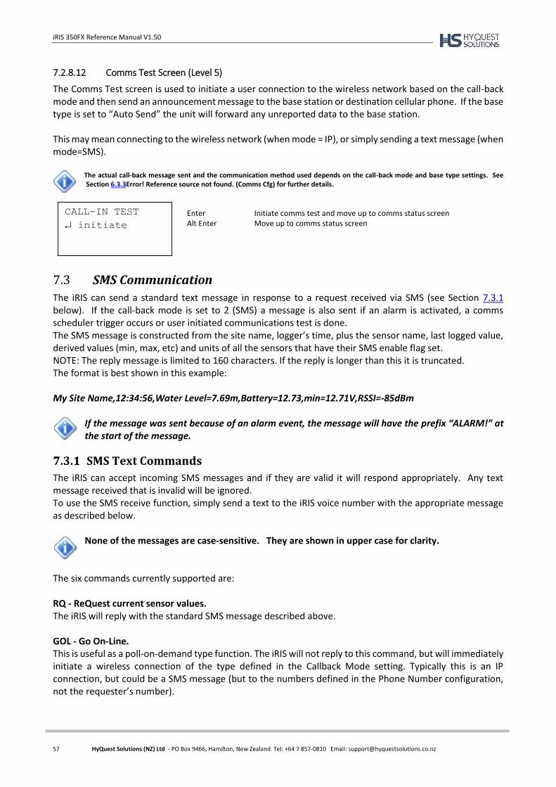
iRIS 350FX Reference Manual V1.50
57 HyQuest Solutions (NZ) Ltd - PO Box 9466, Hamilton, New Zealand Tel: +64 7 857-0810 Email: [email protected]
7.2.8.12 Comms Test Screen (Level 5)
The Comms Test screen is used to initiate a user connection to the wireless network based on the call-back mode and then send an announcement message to the base station or destination cellular phone. If the base type is set to “Auto Send” the unit will forward any unreported data to the base station. This may mean connecting to the wireless network (when mode = IP), or simply sending a text message (when mode=SMS).
The actual call-back message sent and the communication method used depends on the call-back mode and base type settings. See Section 6.3.3Error! Reference source not found. (Comms Cfg) for further details.
SMS Communication
The iRIS can send a standard text message in response to a request received via SMS (see Section 7.3.1 below). If the call-back mode is set to 2 (SMS) a message is also sent if an alarm is activated, a comms scheduler trigger occurs or user initiated communications test is done. The SMS message is constructed from the site name, logger’s time, plus the sensor name, last logged value, derived values (min, max, etc) and units of all the sensors that have their SMS enable flag set. NOTE: The reply message is limited to 160 characters. If the reply is longer than this it is truncated. The format is best shown in this example: My Site Name,12:34:56,Water Level=7.69m,Battery=12.73,min=12.71V,RSSI=-85dBm
If the message was sent because of an alarm event, the message will have the prefix “ALARM!” at the start of the message.
SMS Text Commands
The iRIS can accept incoming SMS messages and if they are valid it will respond appropriately. Any text message received that is invalid will be ignored. To use the SMS receive function, simply send a text to the iRIS voice number with the appropriate message as described below.
None of the messages are case-sensitive. They are shown in upper case for clarity.
The six commands currently supported are: RQ - ReQuest current sensor values. The iRIS will reply with the standard SMS message described above. GOL - Go On-Line. This is useful as a poll-on-demand type function. The iRIS will not reply to this command, but will immediately initiate a wireless connection of the type defined in the Callback Mode setting. Typically this is an IP connection, but could be a SMS message (but to the numbers defined in the Phone Number configuration, not the requester’s number).
CALL-IN TEST
initiate
Enter Initiate comms test and move up to comms status screen Alt Enter Move up to comms status screen
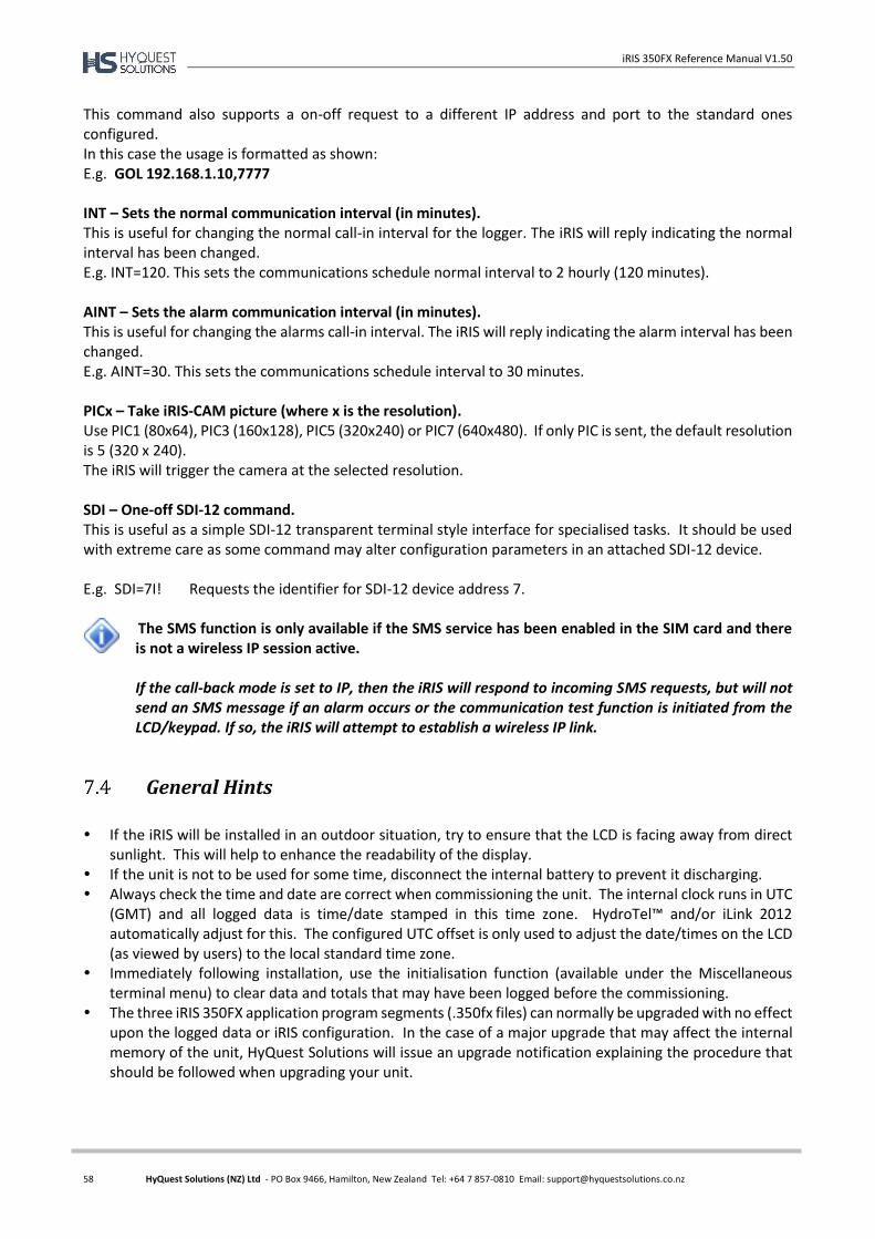
iRIS 350FX Reference Manual V1.50
58 HyQuest Solutions (NZ) Ltd - PO Box 9466, Hamilton, New Zealand Tel: +64 7 857-0810 Email: [email protected]
This command also supports a on-off request to a different IP address and port to the standard ones configured. In this case the usage is formatted as shown: E.g. GOL 192.168.1.10,7777 INT – Sets the normal communication interval (in minutes). This is useful for changing the normal call-in interval for the logger. The iRIS will reply indicating the normal interval has been changed. E.g. INT=120. This sets the communications schedule normal interval to 2 hourly (120 minutes). AINT – Sets the alarm communication interval (in minutes). This is useful for changing the alarms call-in interval. The iRIS will reply indicating the alarm interval has been changed. E.g. AINT=30. This sets the communications schedule interval to 30 minutes. PICx – Take iRIS-CAM picture (where x is the resolution). Use PIC1 (80x64), PIC3 (160x128), PIC5 (320x240) or PIC7 (640x480). If only PIC is sent, the default resolution is 5 (320 x 240). The iRIS will trigger the camera at the selected resolution. SDI – One-off SDI-12 command. This is useful as a simple SDI-12 transparent terminal style interface for specialised tasks. It should be used with extreme care as some command may alter configuration parameters in an attached SDI-12 device. E.g. SDI=7I! Requests the identifier for SDI-12 device address 7.
The SMS function is only available if the SMS service has been enabled in the SIM card and there is not a wireless IP session active. If the call-back mode is set to IP, then the iRIS will respond to incoming SMS requests, but will not send an SMS message if an alarm occurs or the communication test function is initiated from the LCD/keypad. If so, the iRIS will attempt to establish a wireless IP link.
General Hints
If the iRIS will be installed in an outdoor situation, try to ensure that the LCD is facing away from direct
sunlight. This will help to enhance the readability of the display. If the unit is not to be used for some time, disconnect the internal battery to prevent it discharging. Always check the time and date are correct when commissioning the unit. The internal clock runs in UTC
(GMT) and all logged data is time/date stamped in this time zone. HydroTel™ and/or iLink 2012 automatically adjust for this. The configured UTC offset is only used to adjust the date/times on the LCD (as viewed by users) to the local standard time zone.
Immediately following installation, use the initialisation function (available under the Miscellaneous terminal menu) to clear data and totals that may have been logged before the commissioning.
The three iRIS 350FX application program segments (.350fx files) can normally be upgraded with no effect upon the logged data or iRIS configuration. In the case of a major upgrade that may affect the internal memory of the unit, HyQuest Solutions will issue an upgrade notification explaining the procedure that should be followed when upgrading your unit.
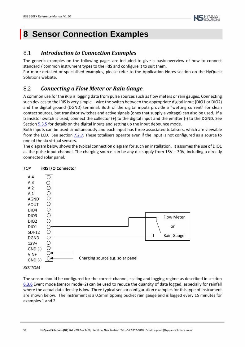
iRIS 350FX Reference Manual V1.50
59 HyQuest Solutions (NZ) Ltd - PO Box 9466, Hamilton, New Zealand Tel: +64 7 857-0810 Email: [email protected]
8 Sensor Connection Examples
Introduction to Connection Examples
The generic examples on the following pages are included to give a basic overview of how to connect standard / common instrument types to the iRIS and configure it to suit them. For more detailed or specialised examples, please refer to the Application Notes section on the HyQuest Solutions website.
Connecting a Flow Meter or Rain Gauge
A common use for the iRIS is logging data from pulse sources such as flow meters or rain gauges. Connecting such devices to the iRIS is very simple – wire the switch between the appropriate digital input (DIO1 or DIO2) and the digital ground (DGND) terminal. Both of the digital inputs provide a “wetting current” for clean contact sources, but transistor switches and active signals (ones that supply a voltage) can also be used. If a transistor switch is used, connect the collector (+) to the digital input and the emitter (-) to the DGND. See Section 5.3.5 for details on the digital inputs and setting up the input debounce mode. Both inputs can be used simultaneously and each input has three associated totalisers, which are viewable from the LCD. See section 7.2.7. These totalisers operate even if the input is not configured as a source to one of the six virtual sensors. The diagram below shows the typical connection diagram for such an installation. It assumes the use of DIO1 as the pulse input channel. The charging source can be any d.c supply from 15V – 30V, including a directly connected solar panel. TOP iRIS I/O Connector
BOTTOM The sensor should be configured for the correct channel, scaling and logging regime as described in section 6.3.6 Event mode (sensor mode=2) can be used to reduce the quantity of data logged, especially for rainfall where the actual data density is low. Three typical sensor configuration examples for this type of instrument are shown below. The instrument is a 0.5mm tipping bucket rain gauge and is logged every 15 minutes for examples 1 and 2.
AI4 AI3 AI2 AI1 AGND AOUT DIO4 DIO3 DIO2 DIO1 SDI-12 DGND 12V+ GND (-) VIN+ GND (-)
Flow Meter
or
Rain Gauge
Charging source e.g. solar panel
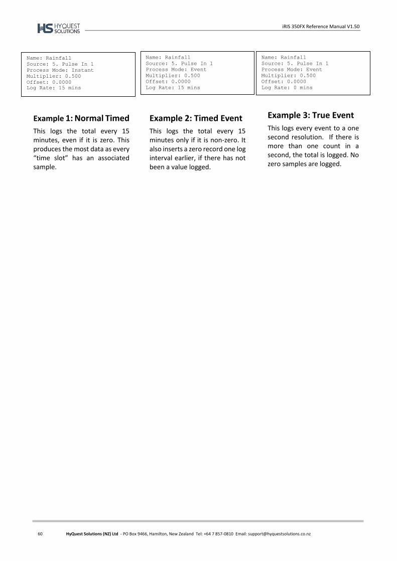
iRIS 350FX Reference Manual V1.50
60 HyQuest Solutions (NZ) Ltd - PO Box 9466, Hamilton, New Zealand Tel: +64 7 857-0810 Email: [email protected]
Name: Rainfall
Source: 5. Pulse In 1
Process Mode: Instant
Multiplier: 0.500
Offset: 0.0000
Log Rate: 15 mins
Name: Rainfall
Source: 5. Pulse In 1
Process Mode: Event
Multiplier: 0.500
Offset: 0.0000
Log Rate: 15 mins
Name: Rainfall
Source: 5. Pulse In 1
Process Mode: Event
Multiplier: 0.500
Offset: 0.0000
Log Rate: 0 mins
Example 1: Normal Timed
This logs the total every 15 minutes, even if it is zero. This produces the most data as every “time slot” has an associated sample.
Example 2: Timed Event
This logs the total every 15 minutes only if it is non-zero. It also inserts a zero record one log interval earlier, if there has not been a value logged.
Example 3: True Event
This logs every event to a one second resolution. If there is more than one count in a second, the total is logged. No zero samples are logged.
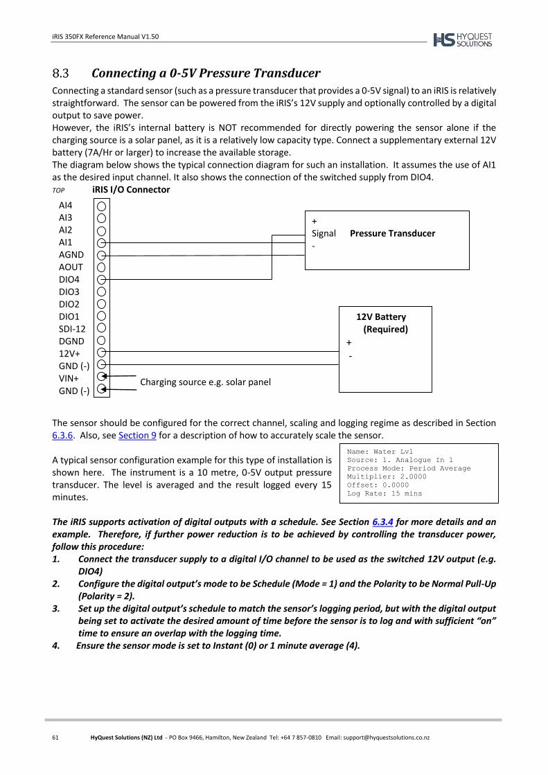
iRIS 350FX Reference Manual V1.50
61 HyQuest Solutions (NZ) Ltd - PO Box 9466, Hamilton, New Zealand Tel: +64 7 857-0810 Email: [email protected]
Connecting a 0-5V Pressure Transducer
Connecting a standard sensor (such as a pressure transducer that provides a 0-5V signal) to an iRIS is relatively straightforward. The sensor can be powered from the iRIS’s 12V supply and optionally controlled by a digital output to save power. However, the iRIS’s internal battery is NOT recommended for directly powering the sensor alone if the charging source is a solar panel, as it is a relatively low capacity type. Connect a supplementary external 12V battery (7A/Hr or larger) to increase the available storage. The diagram below shows the typical connection diagram for such an installation. It assumes the use of AI1 as the desired input channel. It also shows the connection of the switched supply from DIO4. TOP iRIS I/O Connector
The sensor should be configured for the correct channel, scaling and logging regime as described in Section 6.3.6. Also, see Section 9 for a description of how to accurately scale the sensor. A typical sensor configuration example for this type of installation is shown here. The instrument is a 10 metre, 0-5V output pressure transducer. The level is averaged and the result logged every 15 minutes. The iRIS supports activation of digital outputs with a schedule. See Section 6.3.4 for more details and an example. Therefore, if further power reduction is to be achieved by controlling the transducer power, follow this procedure: 1. Connect the transducer supply to a digital I/O channel to be used as the switched 12V output (e.g.
DIO4) 2. Configure the digital output’s mode to be Schedule (Mode = 1) and the Polarity to be Normal Pull-Up
(Polarity = 2). 3. Set up the digital output’s schedule to match the sensor’s logging period, but with the digital output
being set to activate the desired amount of time before the sensor is to log and with sufficient “on” time to ensure an overlap with the logging time.
4. Ensure the sensor mode is set to Instant (0) or 1 minute average (4).
AI4 AI3 AI2 AI1 AGND AOUT DIO4 DIO3 DIO2 DIO1 SDI-12 DGND 12V+ GND (-) VIN+ GND (-)
+ Signal Pressure Transducer -
Charging source e.g. solar panel
12V Battery (Required)
+ -
Name: Water Lvl
Source: 1. Analogue In 1
Process Mode: Period Average
Multiplier: 2.0000
Offset: 0.0000
Log Rate: 15 mins
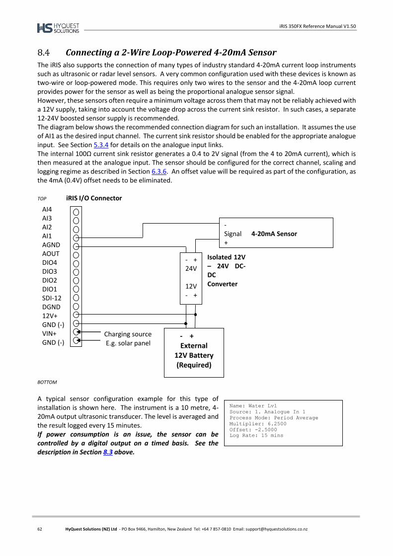
iRIS 350FX Reference Manual V1.50
62 HyQuest Solutions (NZ) Ltd - PO Box 9466, Hamilton, New Zealand Tel: +64 7 857-0810 Email: [email protected]
Connecting a 2-Wire Loop-Powered 4-20mA Sensor
The iRIS also supports the connection of many types of industry standard 4-20mA current loop instruments such as ultrasonic or radar level sensors. A very common configuration used with these devices is known as two-wire or loop-powered mode. This requires only two wires to the sensor and the 4-20mA loop current provides power for the sensor as well as being the proportional analogue sensor signal. However, these sensors often require a minimum voltage across them that may not be reliably achieved with a 12V supply, taking into account the voltage drop across the current sink resistor. In such cases, a separate 12-24V boosted sensor supply is recommended. The diagram below shows the recommended connection diagram for such an installation. It assumes the use of AI1 as the desired input channel. The current sink resistor should be enabled for the appropriate analogue input. See Section 5.3.4 for details on the analogue input links. The internal 100Ω current sink resistor generates a 0.4 to 2V signal (from the 4 to 20mA current), which is then measured at the analogue input. The sensor should be configured for the correct channel, scaling and logging regime as described in Section 6.3.6. An offset value will be required as part of the configuration, as the 4mA (0.4V) offset needs to be eliminated. TOP iRIS I/O Connector
BOTTOM
A typical sensor configuration example for this type of installation is shown here. The instrument is a 10 metre, 4-20mA output ultrasonic transducer. The level is averaged and the result logged every 15 minutes. If power consumption is an issue, the sensor can be controlled by a digital output on a timed basis. See the description in Section 8.3 above.
Isolated 12V – 24V DC- DC Converter
- + 24V 12V - +
Charging source E.g. solar panel
- + External
12V Battery (Required)
- Signal 4-20mA Sensor +
AI4 AI3 AI2 AI1 AGND AOUT DIO4 DIO3 DIO2 DIO1 SDI-12 DGND 12V+ GND (-) VIN+ GND (-)
Name: Water Lvl
Source: 1. Analogue In 1
Process Mode: Period Average
Multiplier: 6.2500
Offset: -2.5000
Log Rate: 15 mins
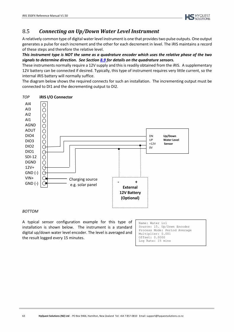
iRIS 350FX Reference Manual V1.50
63 HyQuest Solutions (NZ) Ltd - PO Box 9466, Hamilton, New Zealand Tel: +64 7 857-0810 Email: [email protected]
Connecting an Up/Down Water Level Instrument
A relatively common type of digital water level instrument is one that provides two pulse outputs. One output generates a pulse for each increment and the other for each decrement in level. The iRIS maintains a record of these steps and therefore the relative level. This instrument type is NOT the same as a quadrature encoder which uses the relative phase of the two signals to determine direction. See Section 8.9 for details on the quadrature sensors. These instruments normally require a 12V supply and this is readily obtained from the iRIS. A supplementary 12V battery can be connected if desired. Typically, this type of instrument requires very little current, so the internal iRIS battery will normally suffice. The diagram below shows the required connects for such an installation. The incrementing output must be connected to DI1 and the decrementing output to DI2. TOP iRIS I/O Connector
BOTTOM A typical sensor configuration example for this type of installation is shown below. The instrument is a standard digital up/down water level encoder. The level is averaged and the result logged every 15 minutes.
AI4 AI3 AI2 AI1 AGND AOUT DIO4 DIO3 DIO2 DIO1 SDI-12 DGND 12V+ GND (-) VIN+ GND (-) - +
External 12V Battery (Optional)
DN Up/Down UP Water Level +12V Sensor 0V
Charging source e.g. solar panel
Name: Water Lvl
Source: 15. Up/Down Encoder
Process Mode: Period Average
Multiplier: 0.001
Offset: 0.0000
Log Rate: 15 mins
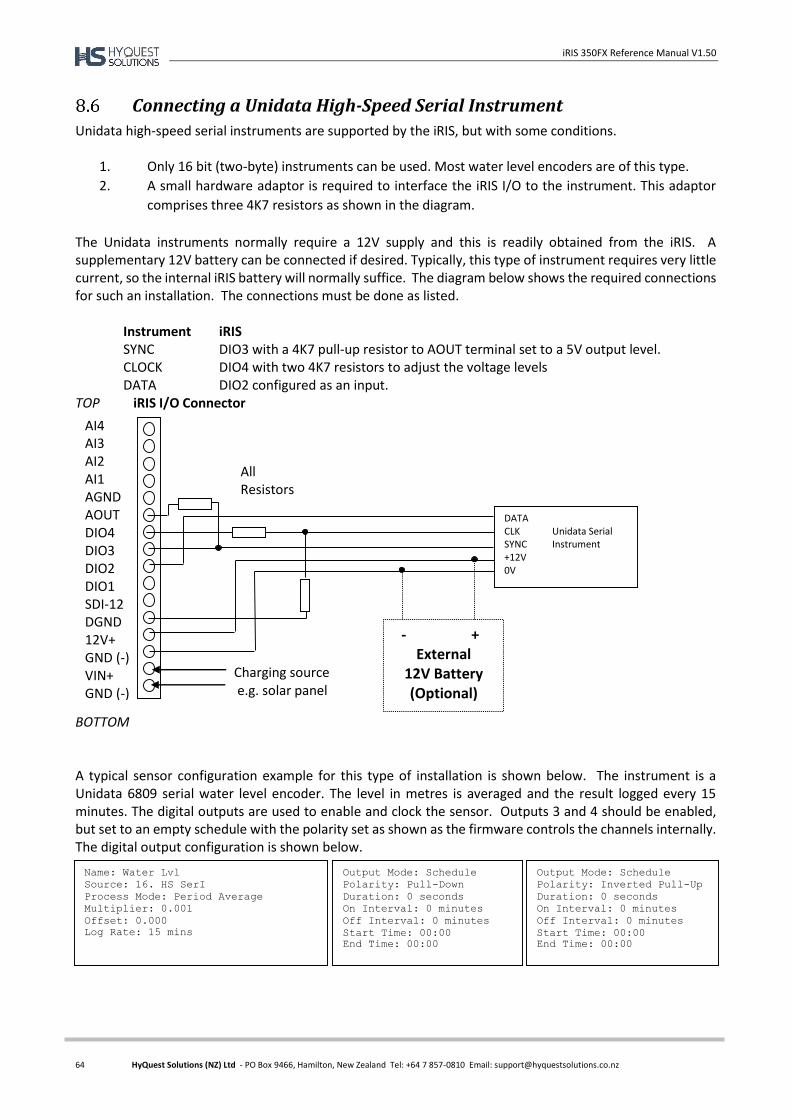
iRIS 350FX Reference Manual V1.50
64 HyQuest Solutions (NZ) Ltd - PO Box 9466, Hamilton, New Zealand Tel: +64 7 857-0810 Email: [email protected]
Connecting a Unidata High-Speed Serial Instrument
Unidata high-speed serial instruments are supported by the iRIS, but with some conditions.
1. Only 16 bit (two-byte) instruments can be used. Most water level encoders are of this type.
2. A small hardware adaptor is required to interface the iRIS I/O to the instrument. This adaptor
comprises three 4K7 resistors as shown in the diagram.
The Unidata instruments normally require a 12V supply and this is readily obtained from the iRIS. A supplementary 12V battery can be connected if desired. Typically, this type of instrument requires very little current, so the internal iRIS battery will normally suffice. The diagram below shows the required connections for such an installation. The connections must be done as listed. Instrument iRIS
SYNC DIO3 with a 4K7 pull-up resistor to AOUT terminal set to a 5V output level. CLOCK DIO4 with two 4K7 resistors to adjust the voltage levels DATA DIO2 configured as an input.
TOP iRIS I/O Connector
BOTTOM A typical sensor configuration example for this type of installation is shown below. The instrument is a Unidata 6809 serial water level encoder. The level in metres is averaged and the result logged every 15 minutes. The digital outputs are used to enable and clock the sensor. Outputs 3 and 4 should be enabled, but set to an empty schedule with the polarity set as shown as the firmware controls the channels internally. The digital output configuration is shown below.
AI4 AI3 AI2 AI1 AGND AOUT DIO4 DIO3 DIO2 DIO1 SDI-12 DGND 12V+ GND (-) VIN+ GND (-)
- + External
12V Battery (Optional)
DATA CLK Unidata Serial SYNC Instrument +12V 0V
Charging source e.g. solar panel
All Resistors
4K7 5%
Name: Water Lvl
Source: 16. HS SerI
Process Mode: Period Average
Multiplier: 0.001
Offset: 0.000
Log Rate: 15 mins
Output Mode: Schedule
Polarity: Pull-Down
Duration: 0 seconds
On Interval: 0 minutes
Off Interval: 0 minutes
Start Time: 00:00
End Time: 00:00
Output Mode: Schedule
Polarity: Inverted Pull-Up
Duration: 0 seconds
On Interval: 0 minutes
Off Interval: 0 minutes
Start Time: 00:00
End Time: 00:00
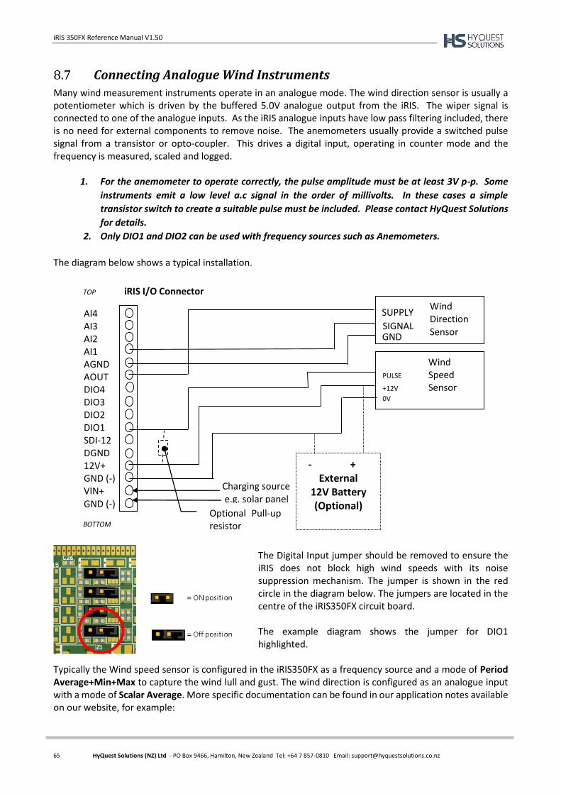
iRIS 350FX Reference Manual V1.50
65 HyQuest Solutions (NZ) Ltd - PO Box 9466, Hamilton, New Zealand Tel: +64 7 857-0810 Email: [email protected]
Connecting Analogue Wind Instruments
Many wind measurement instruments operate in an analogue mode. The wind direction sensor is usually a potentiometer which is driven by the buffered 5.0V analogue output from the iRIS. The wiper signal is connected to one of the analogue inputs. As the iRIS analogue inputs have low pass filtering included, there is no need for external components to remove noise. The anemometers usually provide a switched pulse signal from a transistor or opto-coupler. This drives a digital input, operating in counter mode and the frequency is measured, scaled and logged.
1. For the anemometer to operate correctly, the pulse amplitude must be at least 3V p-p. Some
instruments emit a low level a.c signal in the order of millivolts. In these cases a simple
transistor switch to create a suitable pulse must be included. Please contact HyQuest Solutions
for details.
2. Only DIO1 and DIO2 can be used with frequency sources such as Anemometers.
The diagram below shows a typical installation.
The Digital Input jumper should be removed to ensure the iRIS does not block high wind speeds with its noise suppression mechanism. The jumper is shown in the red circle in the diagram below. The jumpers are located in the centre of the iRIS350FX circuit board. The example diagram shows the jumper for DIO1 highlighted.
Typically the Wind speed sensor is configured in the iRIS350FX as a frequency source and a mode of Period Average+Min+Max to capture the wind lull and gust. The wind direction is configured as an analogue input with a mode of Scalar Average. More specific documentation can be found in our application notes available on our website, for example:
AI4 AI3 AI2 AI1 AGND AOUT DIO4 DIO3 DIO2 DIO1 SDI-12 DGND 12V+ GND (-) VIN+ GND (-)
- + External
12V Battery (Optional)
Wind PULSE Speed +12V Sensor 0V
Charging source e.g. solar panel
SUPPLY SIGNAL GND
Wind Direction Sensor
Optional Pull-up resistor
TOP iRIS I/O Connector
BOTTOM
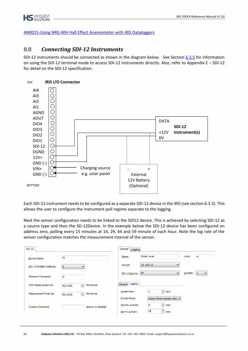
iRIS 350FX Reference Manual V1.50
66 HyQuest Solutions (NZ) Ltd - PO Box 9466, Hamilton, New Zealand Tel: +64 7 857-0810 Email: [email protected]
AN0015-Using NRG 40H Hall Effect Anemometer with iRIS Dataloggers
Connecting SDI-12 Instruments
SDI-12 instruments should be connected as shown in the diagram below. See Section 6.3.5 for information on using the SDI-12 terminal mode to access SDI-12 instruments directly. Also, refer to Appendix E – SDI-12 for detail on the SDI-12 specification.
Each SDI-12 instrument needs to be configured as a separate SDI-12 device in the iRIS (see section 6.3.5). This allows the user to configure the instrument poll regime separate to the logging. Next the sensor configuration needs to be linked to the SDI12 device. This is achieved by selecting SDI-12 as a source type and then the SD-12Device. In the example below the SDI-12 device has been configured on address zero, polling every 15 minutes at 14, 29, 44 and 59 minute of each hour. Note the log rate of the sensor configuration matches the measurement interval of the sensor.
AI4 AI3 AI2 AI1 AGND AOUT DIO4 DIO3 DIO2 DIO1 SDI-12 DGND 12V+ GND (-) VIN+ GND (-)
- + External
12V Battery (Optional)
DATA SDI-12 +12V Instrument(s) 0V
Charging source e.g. solar panel
TOP iRIS I/O Connector
BOTTOM

iRIS 350FX Reference Manual V1.50
67 HyQuest Solutions (NZ) Ltd - PO Box 9466, Hamilton, New Zealand Tel: +64 7 857-0810 Email: [email protected]
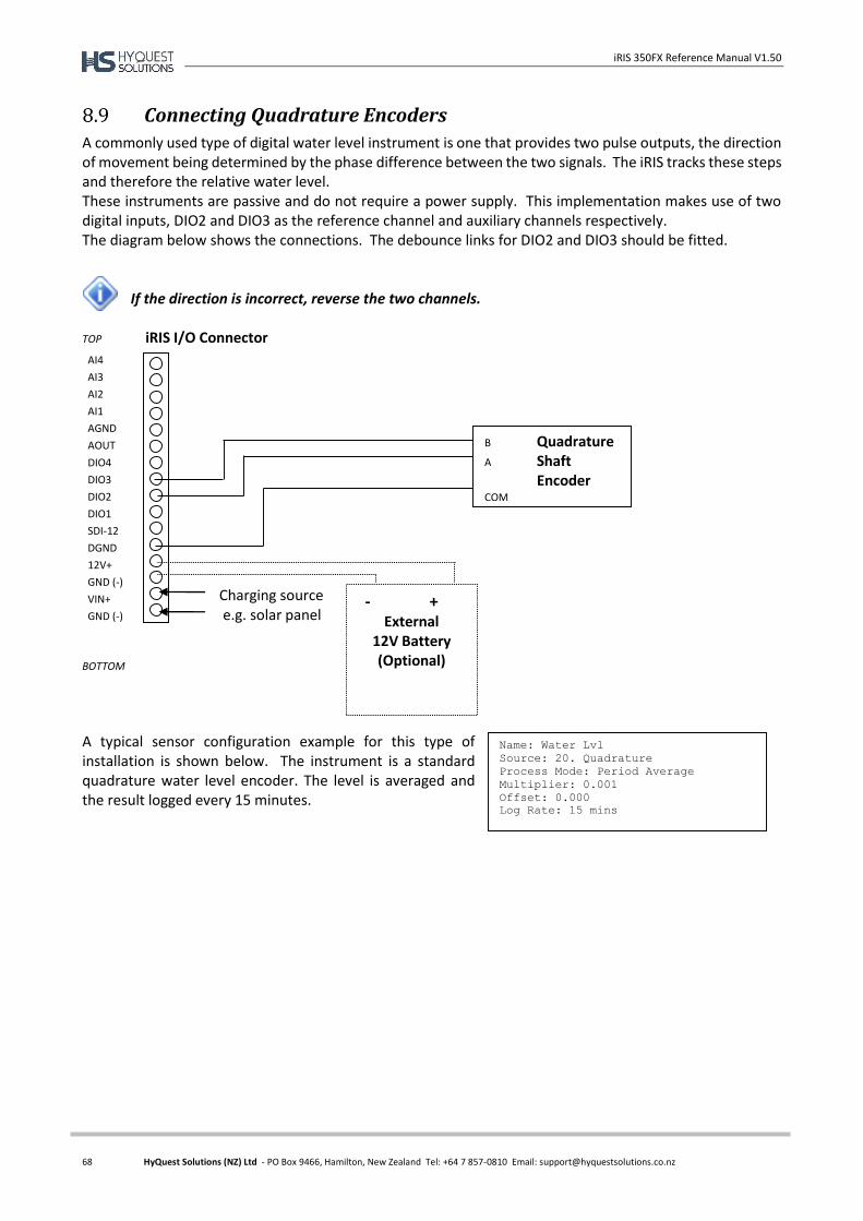
iRIS 350FX Reference Manual V1.50
68 HyQuest Solutions (NZ) Ltd - PO Box 9466, Hamilton, New Zealand Tel: +64 7 857-0810 Email: [email protected]
Connecting Quadrature Encoders
A commonly used type of digital water level instrument is one that provides two pulse outputs, the direction of movement being determined by the phase difference between the two signals. The iRIS tracks these steps and therefore the relative water level. These instruments are passive and do not require a power supply. This implementation makes use of two digital inputs, DIO2 and DIO3 as the reference channel and auxiliary channels respectively. The diagram below shows the connections. The debounce links for DIO2 and DIO3 should be fitted.
If the direction is incorrect, reverse the two channels.
TOP iRIS I/O Connector BOTTOM
A typical sensor configuration example for this type of installation is shown below. The instrument is a standard quadrature water level encoder. The level is averaged and the result logged every 15 minutes.
- + External
12V Battery (Optional)
B Quadrature A Shaft Encoder COM
Charging source e.g. solar panel
AI4
AI3
AI2
AI1
AGND
AOUT
DIO4
DIO3
DIO2
DIO1
SDI-12
DGND
12V+
GND (-)
VIN+
GND (-)
Name: Water Lvl
Source: 20. Quadrature
Process Mode: Period Average
Multiplier: 0.001
Offset: 0.000
Log Rate: 15 mins
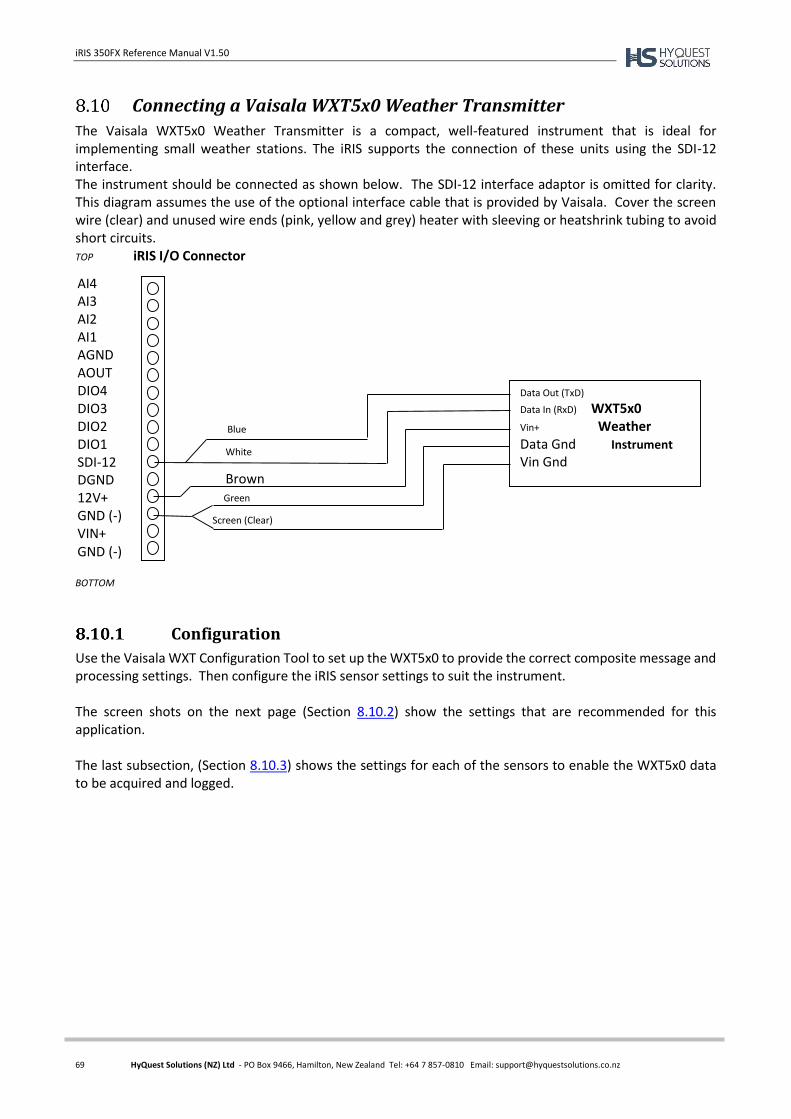
iRIS 350FX Reference Manual V1.50
69 HyQuest Solutions (NZ) Ltd - PO Box 9466, Hamilton, New Zealand Tel: +64 7 857-0810 Email: [email protected]
Connecting a Vaisala WXT5x0 Weather Transmitter
The Vaisala WXT5x0 Weather Transmitter is a compact, well-featured instrument that is ideal for implementing small weather stations. The iRIS supports the connection of these units using the SDI-12 interface. The instrument should be connected as shown below. The SDI-12 interface adaptor is omitted for clarity. This diagram assumes the use of the optional interface cable that is provided by Vaisala. Cover the screen wire (clear) and unused wire ends (pink, yellow and grey) heater with sleeving or heatshrink tubing to avoid short circuits. TOP iRIS I/O Connector BOTTOM
Configuration
Use the Vaisala WXT Configuration Tool to set up the WXT5x0 to provide the correct composite message and processing settings. Then configure the iRIS sensor settings to suit the instrument. The screen shots on the next page (Section 8.10.2) show the settings that are recommended for this application. The last subsection, (Section 8.10.3) shows the settings for each of the sensors to enable the WXT5x0 data to be acquired and logged.
AI4 AI3 AI2 AI1 AGND AOUT DIO4 DIO3 DIO2 DIO1 SDI-12 DGND 12V+ GND (-) VIN+ GND (-)
Data Out (TxD) Data In (RxD) WXT5x0 Vin+ Weather Data Gnd Instrument Vin Gnd
Green
Brown
Blue
White
Screen (Clear)
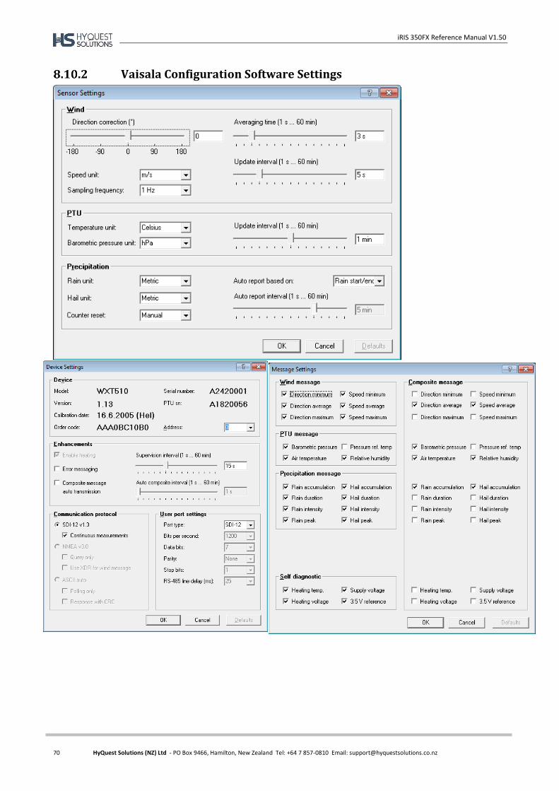
iRIS 350FX Reference Manual V1.50
70 HyQuest Solutions (NZ) Ltd - PO Box 9466, Hamilton, New Zealand Tel: +64 7 857-0810 Email: [email protected]
Vaisala Configuration Software Settings

iRIS 350FX Reference Manual V1.50
71 HyQuest Solutions (NZ) Ltd - PO Box 9466, Hamilton, New Zealand Tel: +64 7 857-0810 Email: [email protected]
iRIS Sensor Configuration
Once the Vaisala has been configured (as shown in Section 8.10.2 above), the iRIS can be then be configured with the following sensor settings:
Name: Wind Dir
Source: 19. SDI-12
SDI-12 Device: WXT510
Variable: 1
Process Mode: Scalar Average
Multiplier: 1.00000
Offset: 0.00000
Log Rate: 5 mins
Name: Wind Spd
Source: 19. SDI-12
SDI-12 Device: WXT510
Variable: 2
Process Mode: Period Average
Log Minimum: Enabled
Log Maximum: Enabled
Multiplier: 1.00000
Offset: 0.00000
Log Rate: 5 mins
Name: Air Temp
Source 19. SDI-12
SDI-12 Device: WXT510
Variable: 3
Process Mode: Instant
Multiplier: 1.00000
Offset: 0.00000
Log Rate: 5 mins
Name: Humidity
Source: 19. SDI-12
SDI-12 Device: WXT510
Variable: 4
Process Mode: Instant
Multiplier: 1.00000
Offset: 0.00000
Log Rate: 5 mins
Name: Hail
Source 19. SDI-12
SDI-12 Device: WXT510
Variable: 7
Process Mode: Instant
Multiplier: 1.00000
Offset: 0.00000
Log Rate: 5 mins
Name: Barometer
Source 19. SDI-12
SDI-12 Device: WXT510
Variable: 5
Process Mode: Instant
Multiplier: 1.00000
Offset: 0.00000
Log Rate: 5 mins
Name: Rainfall
Source 19. SDI-12
SDI-12 Device: WXT510
Variable: 6
Process Mode: Instant
Multiplier: 1.00000
Offset: 0.00000
Log Rate: 5 mins
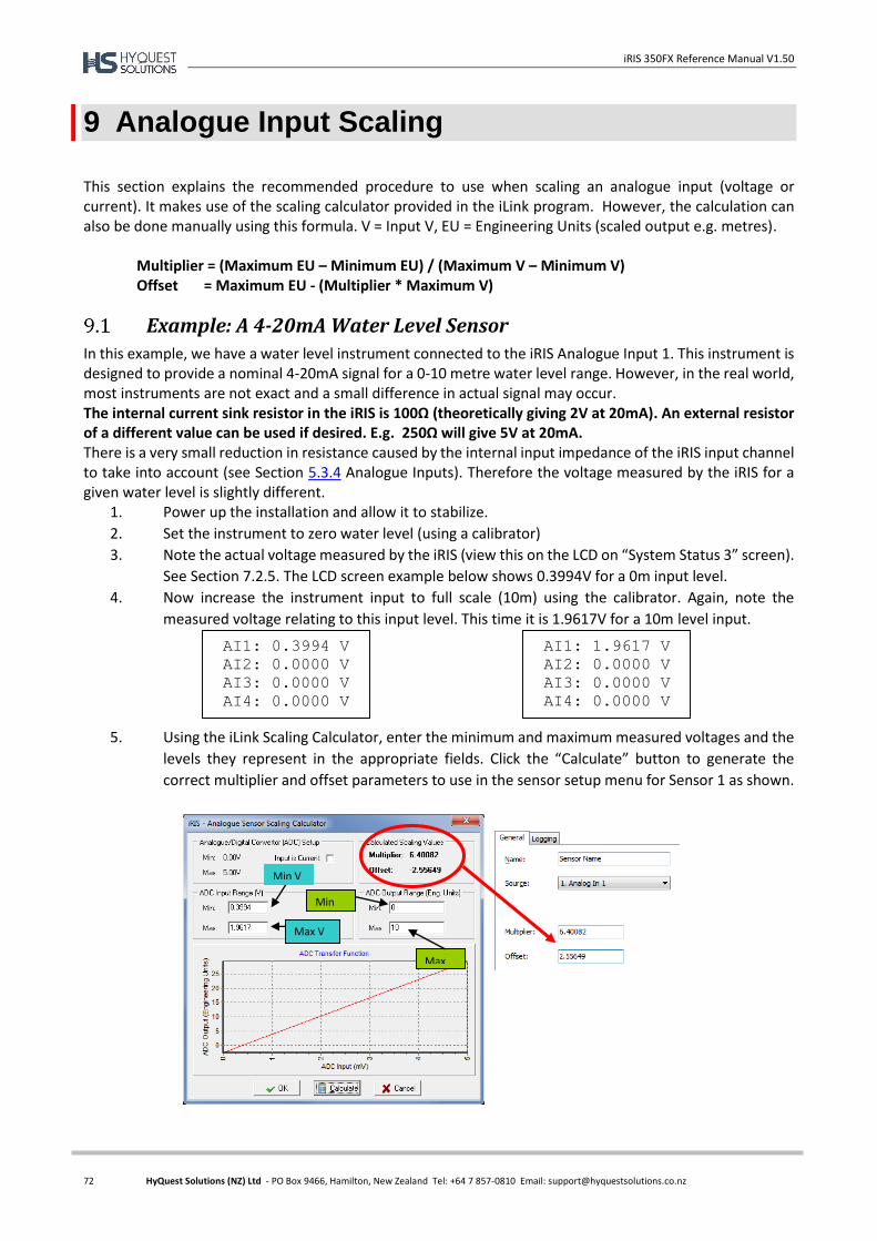
iRIS 350FX Reference Manual V1.50
72 HyQuest Solutions (NZ) Ltd - PO Box 9466, Hamilton, New Zealand Tel: +64 7 857-0810 Email: [email protected]
9 Analogue Input Scaling
This section explains the recommended procedure to use when scaling an analogue input (voltage or current). It makes use of the scaling calculator provided in the iLink program. However, the calculation can also be done manually using this formula. V = Input V, EU = Engineering Units (scaled output e.g. metres).
Multiplier = (Maximum EU – Minimum EU) / (Maximum V – Minimum V) Offset = Maximum EU - (Multiplier * Maximum V)
Example: A 4-20mA Water Level Sensor
In this example, we have a water level instrument connected to the iRIS Analogue Input 1. This instrument is designed to provide a nominal 4-20mA signal for a 0-10 metre water level range. However, in the real world, most instruments are not exact and a small difference in actual signal may occur. The internal current sink resistor in the iRIS is 100Ω (theoretically giving 2V at 20mA). An external resistor of a different value can be used if desired. E.g. 250Ω will give 5V at 20mA. There is a very small reduction in resistance caused by the internal input impedance of the iRIS input channel to take into account (see Section 5.3.4 Analogue Inputs). Therefore the voltage measured by the iRIS for a given water level is slightly different.
1. Power up the installation and allow it to stabilize.
2. Set the instrument to zero water level (using a calibrator)
3. Note the actual voltage measured by the iRIS (view this on the LCD on “System Status 3” screen).
See Section 7.2.5. The LCD screen example below shows 0.3994V for a 0m input level.
4. Now increase the instrument input to full scale (10m) using the calibrator. Again, note the
measured voltage relating to this input level. This time it is 1.9617V for a 10m level input.
5. Using the iLink Scaling Calculator, enter the minimum and maximum measured voltages and the
levels they represent in the appropriate fields. Click the “Calculate” button to generate the
correct multiplier and offset parameters to use in the sensor setup menu for Sensor 1 as shown.
Min V
Max V
Max
Min
WL
AI1: 0.3994 V
AI2: 0.0000 V
AI3: 0.0000 V
AI4: 0.0000 V
AI1: 1.9617 V
AI2: 0.0000 V
AI3: 0.0000 V
AI4: 0.0000 V
iRIS 350FX Reference Manual V1.50
73 HyQuest Solutions (NZ) Ltd - PO Box 9466, Hamilton, New Zealand Tel: +64 7 857-0810 Email: [email protected]
10 RS232 Interface Telemetry / Gateway Comms
Overview
The iRIS may be used to communicate via external telemetry devices such as data radios or modems using its RS232 port. When an external RS232 communication device is connected, the iRIS is also capable of doing “store and forward” or “gateway” communications. This feature allows data packets that are not addressed to this logger to be redirected to other HyQuest Solutions devices. This chapter describes using the RS232 Telemetry function and also explains the gateway communications functionality.
RS232 Port Telemetry
If the RS232 port is to be used for telemetry, then its normal terminal/binary mode at 38400bps is disabled and the port becomes fixed to iQuest binary protocol at the user configured port speed. There are two methods of enabling the RS232 telemetry mode.
RS232 Only Telemetry Mode
If the iRIS does not have an internal wireless modem or else the internal modem is unused, the iRIS can be configured for “RS232 Only” telemetry mode. This mode is controlled by the iRIS software based on various actions (see table below) and the RS232 port does not need a special cable for connection to external communications devices.
In RS232 Only telemetry mode, any call-back messages will always be directed out the RS232 port. This is why telemetry mode is enabled when a user is logged in. It allows call-back testing to be done using the LCD/keypad.
Switching between telemetry and “normal” modes is controlled by the following actions:
Action Mode
Key pressed when user is not logged in Normal
User is logged in Telemetry
User has just logged out Normal
RS232 port activity in terminal or data download modes Kept in Normal
At least 2 minutes of no activity on keypad or RS232 port Telemetry
Table 6 – RS232 Port Telemetry Control
Mode Protocol House Icon RS232 Speed
Normal Terminal or Binary Outline 115200bps
Telemetry Binary Only Filled in with ‘R’ As configured
Table 7 – RS232 Telemetry Mode Indications
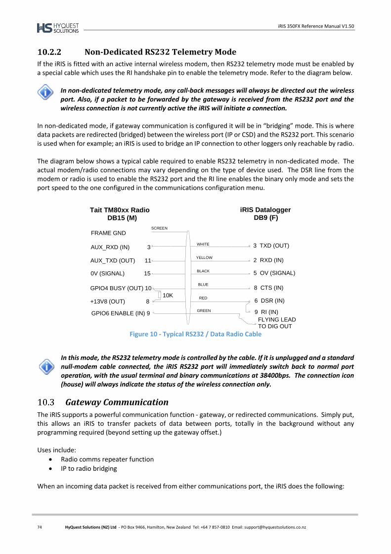
iRIS 350FX Reference Manual V1.50
74 HyQuest Solutions (NZ) Ltd - PO Box 9466, Hamilton, New Zealand Tel: +64 7 857-0810 Email: [email protected]
Non-Dedicated RS232 Telemetry Mode
If the iRIS is fitted with an active internal wireless modem, then RS232 telemetry mode must be enabled by a special cable which uses the RI handshake pin to enable the telemetry mode. Refer to the diagram below.
In non-dedicated telemetry mode, any call-back messages will always be directed out the wireless port. Also, if a packet to be forwarded by the gateway is received from the RS232 port and the wireless connection is not currently active the iRIS will initiate a connection.
In non-dedicated mode, if gateway communication is configured it will be in “bridging” mode. This is where data packets are redirected (bridged) between the wireless port (IP or CSD) and the RS232 port. This scenario is used when for example; an iRIS is used to bridge an IP connection to other loggers only reachable by radio. The diagram below shows a typical cable required to enable RS232 telemetry in non-dedicated mode. The actual modem/radio connections may vary depending on the type of device used. The DSR line from the modem or radio is used to enable the RS232 port and the RI line enables the binary only mode and sets the port speed to the one configured in the communications configuration menu.
Figure 10 - Typical RS232 / Data Radio Cable
In this mode, the RS232 telemetry mode is controlled by the cable. If it is unplugged and a standard null-modem cable connected, the iRIS RS232 port will immediately switch back to normal port operation, with the usual terminal and binary communications at 38400bps. The connection icon (house) will always indicate the status of the wireless connection only.
Gateway Communication
The iRIS supports a powerful communication function - gateway, or redirected communications. Simply put, this allows an iRIS to transfer packets of data between ports, totally in the background without any programming required (beyond setting up the gateway offset.) Uses include:
Radio comms repeater function
IP to radio bridging When an incoming data packet is received from either communications port, the iRIS does the following:
AUX_RXD (IN) 3
AUX_TXD (OUT) 11
0V (SIGNAL) 15
GPIO4 BUSY (OUT) 10
+13V8 (OUT) 8
WHITE
YELLOW
BLACK
BLUE
RED
2 RXD (IN)
3 TXD (OUT)
5 OV (SIGNAL)
8 CTS (IN)
6 DSR (IN)
FRAME GND
Tait TM80xx Radio DB15 (M)
iRIS Datalogger DB9 (F)
SCREEN
9 RI (IN)
10K
FLYING LEADTO DIG OUT
GPIO6 ENABLE (IN) 9GREEN
iRIS 350FX Reference Manual V1.50
75 HyQuest Solutions (NZ) Ltd - PO Box 9466, Hamilton, New Zealand Tel: +64 7 857-0810 Email: [email protected]
Is this message for me? If it is, then accept and process it. Gateway redirection is not needed and no further action is taken.
Check if the iRIS has a gateway offset configured. If it does, then test the destination address in the received packet and see if it falls in the range covered by the gateway. If a match is found, then the packet will have its source and destination addresses changed (aliased) and be transmitted. In non-dedicated mode it will be sent from the other port. In dedicated mode it will be sent from the same port that the packet was received on.
If the packet has not been used by this point then it is rejected and lost.
Note: All retries are the responsibility of the transmission originator. The only setup required to use gateway communications is to set the gateway table offset.
Aliased Gateway explained
The iRIS uses a gateway method called "Aliased Gateway Communication". In other words, it alters the destination and source addresses of a received packet before it is redirected back out via the gateway. The primary reason for this in a radio only situation is to completely separate radio communication paths between stations. This is to avoid a packet that has been redirected through an intermediate station being received and replied to by the far destination station at the same time. This might be due to unusual RF propagation conditions where direct communications is not normally achievable between the originator and destination stations but suddenly becomes possible. By addressing the original packet from the originating node (usually HydroTel™) to a notional (non-existent) number, the gateway iRIS can add an offset to the address (correcting to the real address) and pass it on to the distant node. Any directly received packet will now be ignored by the distant iRIS as the address will not match.
Gateway example
An iRIS, set to address 14, is installed at a hilltop rainfall measuring site. This logger is within range of a wireless network and it uses IP communications with the HydroTel™ base. A second iRIS, which is set to address 67, is installed down in the valley at a water quality site. This site has no wireless network coverage, so a pair of low-power radios is used to link the two sites. Each radio connects to the RS232 port on its respective iRIS logger. The hilltop site uses a special cable (see Figure 10 above) to enable non-dedicated RS232 telemetry mode because it also has wireless connectivity. As the valley site has no modem, it is set to “RS232 only” telemetry mode and it uses a standard RS232 cable to connect to the radio. The HydroTel™ base computer (which has a communications address of 0) needs to access both iRIS loggers. To achieve this, the hilltop iRIS is enabled for gateway communication and for convenience its offset gateway is set to 1000. This means that the site will redirect any packet with a destination address between 1000 and 1099.
To enable alarm call-back from the iRIS at the valley site, its call-back address is also set to 1000 to cause the hilltop gateway logger to redirect messages to the HydroTel™ base.
The only change at the HydroTel™ base is to set the address for the valley site to 1067 in the station configuration form, rather than its actual address of 67. The address gets changed as it passes through the gateway iRIS logger as described below.

iRIS 350FX Reference Manual V1.50
76 HyQuest Solutions (NZ) Ltd - PO Box 9466, Hamilton, New Zealand Tel: +64 7 857-0810 Email: [email protected]
This is what happens to the data packets during a typical requestresponse data conversation.
HydroTel™ sends a request packet to the valley site via IP (which has the same IP address as the hilltop site in HydroTel™). It is addressed to destination address 1067 from sender’s address 0.
The gateway logger matches the destination address (1067) to be in its gateway address range.
The packet’s source and destination addresses are aliased by applying the gateway offset (1000).
The gateway logger sends the aliased packet via the radio down to the remote iRIS. It is now addressed to destination address 67 from sender’s address 1000.
The remote iRIS processes the request and sends back its response via the radio. This packet is addressed to HydroTel™ as destination address 1000 from the valley iRIS sender’s address of 67.
The gateway logger matches the destination address (1000) to be in its gateway address range.
The packet’s source and destination addresses are aliased by applying the gateway offset (1000).
The gateway logger sends the aliased packet via the IP network to the HydroTel™ base. It is now addressed to destination address 0 from sender’s address 1067.

iRIS 350FX Reference Manual V1.50
77 HyQuest Solutions (NZ) Ltd - PO Box 9466, Hamilton, New Zealand Tel: +64 7 857-0810 Email: [email protected]
11 Using Modbus Slave Mode
The Modbus protocol slave mode support is a feature supported by the standard iRIS 350FX program variants. Custom variants do not have support for this feature as the RS232 port is often used by these in a different way. When enabled, the iRIS functions as a simple Modbus slave (server). Third party equipment is the master and can write values to or read values from a set of predefined “holding registers”. In the case of the written holding registers, the iRIS 350FX can be configured to access these values as sources for one or more sensor channels. In order to enable the Modbus operation on the shared RS232 port, the user must do this with the keypad/LCD interface when on site. If Modbus mode is configured, a safety timeout switches back to Modbus after a period of no activity on the port, in the event a user forgets to manually reselect that mode. The iRIS 350FX operates in Modbus RTU mode (Modbus ASCII mode will be added at a later date). Supported port speeds are 1200, 2400, 4800, 9600, 19200, 38400 and 115200bps. Parity in RTU mode is settable to Even, Odd or None. In compliance with the Modbus specification, when parity is set to ‘None’, an extra stop bit is inserted. In RTU mode, 8 data bits are used and in ASCII mode, 7 data bits are used. If the RTU is writing values to the iRIS frequently, then the iRIS can log a period average and minimum and maximum values during the log period as well. There is also a basic write timeout where the holding registers are set to an invalid value after a predetermined time of no write commands being received from the Modbus master. This can be disabled by setting the timeout to zero.
Configuring iRIS 350FX to use Modbus
This section explains how to configure an iRIS 350FX to use Modbus input in iLink 2012. Connect the logger using iLink 2012 and go to the General settings under the Configuration tab. Expand the sensors tree. In the screenshot on the next page, sensor 12 (Modbus) is selected and the ‘Modbus 2 Byte Short’ has been chosen from the source dropdown list. So it will use the values that are written to holding register 40112 for logging (2 Byte Shorts are written in registers 40101-40120 and 4 Byte Floats are written in registers 40201-40240).
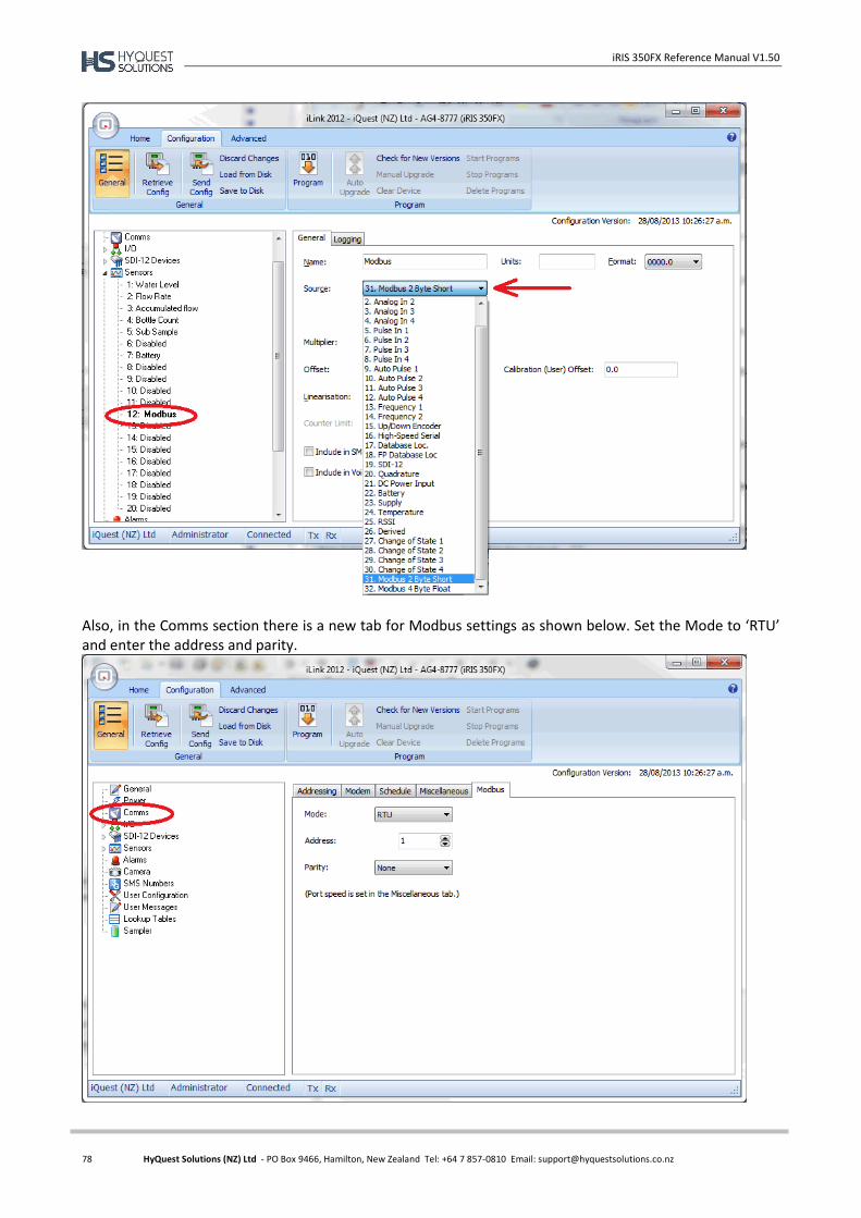
iRIS 350FX Reference Manual V1.50
78 HyQuest Solutions (NZ) Ltd - PO Box 9466, Hamilton, New Zealand Tel: +64 7 857-0810 Email: [email protected]
Also, in the Comms section there is a new tab for Modbus settings as shown below. Set the Mode to ‘RTU’ and enter the address and parity.
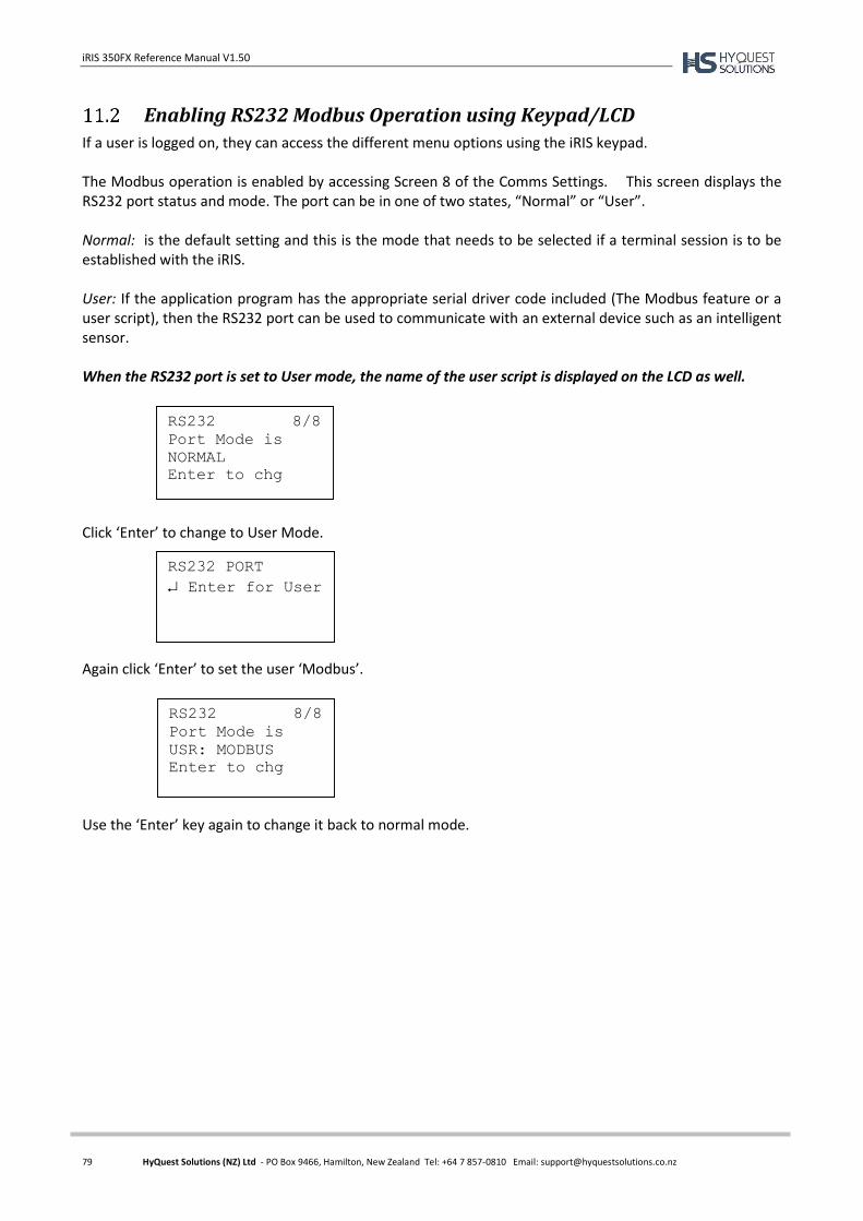
iRIS 350FX Reference Manual V1.50
79 HyQuest Solutions (NZ) Ltd - PO Box 9466, Hamilton, New Zealand Tel: +64 7 857-0810 Email: [email protected]
Enabling RS232 Modbus Operation using Keypad/LCD
If a user is logged on, they can access the different menu options using the iRIS keypad. The Modbus operation is enabled by accessing Screen 8 of the Comms Settings. This screen displays the RS232 port status and mode. The port can be in one of two states, “Normal” or “User”. Normal: is the default setting and this is the mode that needs to be selected if a terminal session is to be established with the iRIS. User: If the application program has the appropriate serial driver code included (The Modbus feature or a user script), then the RS232 port can be used to communicate with an external device such as an intelligent sensor. When the RS232 port is set to User mode, the name of the user script is displayed on the LCD as well. Click ‘Enter’ to change to User Mode. Again click ‘Enter’ to set the user ‘Modbus’. Use the ‘Enter’ key again to change it back to normal mode.
RS232 8/8
Port Mode is
NORMAL
Enter to chg
RS232 PORT
Enter for User
RS232 8/8
Port Mode is
USR: MODBUS
Enter to chg
iRIS 350FX Reference Manual V1.50
80 HyQuest Solutions (NZ) Ltd - PO Box 9466, Hamilton, New Zealand Tel: +64 7 857-0810 Email: [email protected]
12 Troubleshooting
This section offers possible answers to common installation and/or configuration issues.
Can’t connect to the iRIS via the RS232 port.
Check that the PC application (iLink or terminal program such as HyperTerminal®) is set for the correct comms port and speed (38400bps). Also check that the iRIS is not in RS232 Only Telemetry mode. This is indicated by a solid black house icon with an ‘R’ symbol in it being displayed on the LCD. If it is in this telemetry mode, switch back to normal mode by pressing any key or if currently logged in, then log out by pressing Alt-Enter from a top level screen. See Section 10.2 for details on using RS232 Telemetry mode.
iRIS will not start when the battery is first connected.
Check that the battery voltage is at least 12.2V. The internal battery management hardware is designed to shut the unit down when the battery becomes discharged to a certain point. It will not restart unless the battery is deemed to have sufficient capacity for normal operation.
Pulse lost when iRIS connected to other equipment.
In almost all installations where an iRIS is connected in parallel with other equipment to share a common pulse input (e.g. from a flow meter) there has not been a detrimental effect, as the iRIS presents a relatively high impedance to the circuit. However, in the event that connecting an iRIS does cause pulse failure, try removing the debounce selection link for the appropriate input. This sets the input to electronic switching mode, even if the actual pulse source is a clean contact (reed switch or similar).
Unable to connect to an IP network.
SIM Card: Check the SIM card is active and enabled for IP connectivity service. APN: The unit must be configured for a valid APN that must also match the SIM account APN. Signal: The iRIS will not attempt to connect if the RSSI is 0 or < -113dBm. Use a higher gain antenna
if the signal strength is marginal. IP Settings: The iRIS will not attempt to connect unless both the primary and secondary base settings are
defined. (IP addresses and port numbers are non-zero). If the secondary base is not used, set it to the same values as the primary base.
See Appendix I for a list of the network settings for the HyQuest Solutions APN or HyQuest Solutions Global Data Network.
iRIS will not respond to SMS requests.
Account: Check the account is active and the SMS service is enabled. Power Mode: If full power save is selected, the wireless modem is shut down. Connection: If the iRIS is connected on an IP session, the SMS feature is unavailable. Use a scheduled IP
connection to minimise the time that SMS is unavailable. Voice Call: If an iRIS 350FXV is connected on a voice call, the SMS feature is unavailable.
iRIS 350FXV answers a voice call, but no sound is heard.
If the iRIS is currently connected to the wireless network with an IP link the iRIS voice processing function is disabled. However the internal modem may still answer the incoming call independently but have no audio available.
iRIS 350FX Reference Manual V1.50
81 HyQuest Solutions (NZ) Ltd - PO Box 9466, Hamilton, New Zealand Tel: +64 7 857-0810 Email: [email protected]
Set the IP connectivity using the scheduler so that it has a high availability for voice (short on-line sessions).
Unable to access terminal menu.
If the security code has been enabled and this is unknown, then access is not possible. Please contact the person responsible for setting the code in the first instance. The code is set by an authorised user using iLink. However, if the security code is known and yet access is still denied, check the case of the entry is correct. E.g. Caps Lock key is not on. The code is case-sensitive and must match exactly.
Digital Output activates when user is logged on.
This indicates the output is set to a scheduled mode with special features enabled. This mode is to enable easy sensor calibration or radio communication testing when the sensor or radio is controlled by a scheduled digital output. Otherwise the person on site would have to wait until the next scheduled operation to be able to perform the test.
SDI-12 sensors log a “NaN” value.
Until an SDI-12 instrument has communicated correctly at least once, all sensors logging values from it are inhibited. So no logging occurs until the first good measurement is obtained. If, later the instrument fails to respond all sensors using values from the instrument will use the error value of NaN (Not a Number).
Sensor values not included in SMS reply to “RQ”.
Whether or not a sensor is included in the SMS reply is controlled by the “Include in Voice/SMS” checkbox in the sensor configuration in iLink or HydroTel™. This enables only the wanted sensors to be included. Ensure that required sensors have this checkbox enabled and the updated configuration has been sent to the iRIS 350FX.
External 12V battery not charging as expected.
This effect can occur when a large capacity external 12V lead acid battery and large solar panel are installed. Over time, if the total current consumption of the iRIS and/or external equipment is significant, the battery voltage may start to fall, despite a daily charging “spike” in sunlight being observed. This may be due to the iRIS internal charger reaching its designed input current limit (approx. 900mA) which means the battery progressively falls behind and may not reach full charge. For sites with a large solar panel (20watt or greater) an external solar regulator is recommended.

iRIS 350FX Reference Manual V1.50
82 HyQuest Solutions (NZ) Ltd - PO Box 9466, Hamilton, New Zealand Tel: +64 7 857-0810 Email: [email protected]
13 Appendix A – Specific Information
General Characteristics
The iRIS 350FX is supplied in an environmentally sealed (IP66) enclosure constructed from a special corrosion-resistant aluminium alloy that is finished in a hard-anodised coating. This provides a very high degree of mechanical strength and EMI shielding, and enables completely stand-alone mounting in outdoor situations. The unit comes standard with an integral 12V gel-cell battery, membrane keypad and a 4 lines x 19 characters (plus icons) LCD. The iRIS 350FX supports a maximum of twenty external sensors (1-20). Sources for these sensors may be chosen from physical digital or analogue inputs or virtual sources (via serial communication or calculations). Sources may also be from internal measurements (battery voltage, supply voltage, temperature and RSSI). Each sensor has six associated alarms, each with separate trigger and reset levels. Each alarm also has a duration, which is used to delay the alarm trigger for analogue inputs and to determine the time over which pulse input counters should be totalised (rainfall etc). Data from all enabled sensors are logged in a four word (8 byte) compressed format which includes full date and time stamp to a 1 second resolution. The iRIS 350FX supports SDI-12 communication with a range of industry standard intelligent sensors. A variant of the iRIS 350FX which is designated the iRIS 350FXV offers voice annunciation of sensor values using the voice bearer of the wireless service. The iRIS 350FX supports the connection of a proprietary serial camera, the iRIS-CAM. This enables the iRIS to capture colour images which can be unloaded in the same way as logged data. Due to resource limitations, the iRIS 350FXV is unable to support the iRIS-CAM in conjunction with the voice feature.
Figure 11 - iRIS 350FX External View
iRIS 350FX Reference Manual V1.50
83 HyQuest Solutions (NZ) Ltd - PO Box 9466, Hamilton, New Zealand Tel: +64 7 857-0810 Email: [email protected]
Technical Specifications
Dimensions: 160mm x 130mm x 67mm (6.30in x 5.11in x 2.64in) (Excluding glands) Mass: 1450g (3.19lb) with gel-cell battery fitted.
Power Supply: Internal 12V @ 0.8A/Hr rechargeable sealed lead acid battery. Can also connect an external regulated 12V dc power supply or rechargeable sealed lead-acid battery.
Charger Supply: External 15-30Vdc supply. Supports a directly connected solar panel (no regulator). Power Consumption: Less than 6mA @ 12V in idle mode. Actual current consumption is dependent on
power management mode, wireless modem state and I/O configuration.
Comms Interfaces: 1x RS232 DB9, 38,400 bps, DTE configuration. 1x Integral multi-band wireless modem or 1x Plug-in comms adaptor E.g. Ethernet, satellite etc. Requires PCB Rev 1.2+
Digital I/O: 4 x Digital Inputs/Outputs. Each channel configurable as either an input or output. Digital Input Mode:
- 30Vdc maximum input, switch to 0Vdc to activate. - Link selectable for either mechanical (<20Hz) or electronic (<5kHz) switching. Digital Output Mode: When set for output, the channel can be either: - Switched 12V out (max 100mA) or - Open-drain pull-down (max 100mA @ 30V)
Analogue I/O: 4 x 16 bit uni-polar analogue inputs. Range 0 – 5.000V. Input impedance 98kΩ.
Referenced to 0V common. Internal measurements available for monitoring are:
Battery Voltage
Supply Voltage
Internal Temperature (C or F)
Received Signal Strength (RSSI or RSCP)
Link selectable for either voltage (0-5V) or current (0-20mA) mode. Integral current mode resistor value 100R.
SDI-12 Interface: SDI-12 hardware interface that fully complies with the SDI-12 electrical standard. Software support to SDI-12 standard 1.3.
Logging Memory: Non-volatile 8MB flash storage of 1,085,476 time/date stamped data points. Circular
buffer mode (overwrites oldest data when memory full). A typical site with 2 parameters logged every 15 minutes plus battery voltage logged hourly will give 3.3 years of storage before data overwrite occurs.
Audio Memory: iRIS 350FXV only. Non-volatile 8MB flash storage of PCM audio files. Total
cumulative audio playtime 12 minutes at 11.025kHz sampling rate. Clock/Calendar: Non-volatile with user replaceable lithium back-up battery module. Accurate to +/-
20 seconds / month

iRIS 350FX Reference Manual V1.50
84 HyQuest Solutions (NZ) Ltd - PO Box 9466, Hamilton, New Zealand Tel: +64 7 857-0810 Email: [email protected]
Environmental: Storage Temperature: -20C - +85C. (-4F - +185F)
Operating Temperature: -10C - +70C. (14F - +158F) Enclosure sealed to IP66 with gasket and glands.
Mounting: 4 x M4 (3/16”) blind mounting holes in rear of case.
4 x 16mm (¾”) compression glands for power supply and I/O cabling access.
Antenna Connection
The iRIS 350 has an industry standard SMA connector which protrudes through the bottom edge of the enclosure lid. In areas of good signal strength, a small “stubby” or omni-directional type antenna will suffice. In areas of more marginal coverage, the antenna should an external high gain type such as a Yagi, via appropriate low-loss high frequency coaxial cable and male SMA connector.
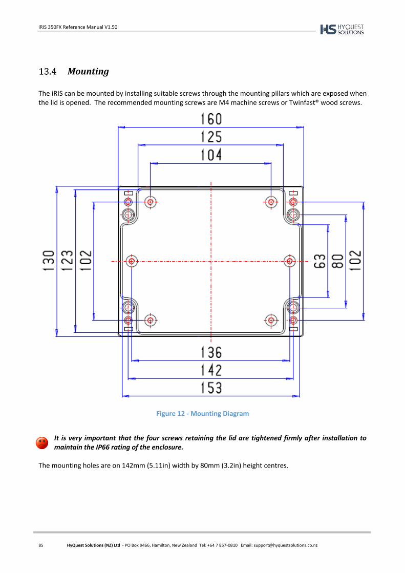
iRIS 350FX Reference Manual V1.50
85 HyQuest Solutions (NZ) Ltd - PO Box 9466, Hamilton, New Zealand Tel: +64 7 857-0810 Email: [email protected]
Mounting
The iRIS can be mounted by installing suitable screws through the mounting pillars which are exposed when the lid is opened. The recommended mounting screws are M4 machine screws or Twinfast® wood screws.
Figure 12 - Mounting Diagram
It is very important that the four screws retaining the lid are tightened firmly after installation to maintain the IP66 rating of the enclosure.
The mounting holes are on 142mm (5.11in) width by 80mm (3.2in) height centres.
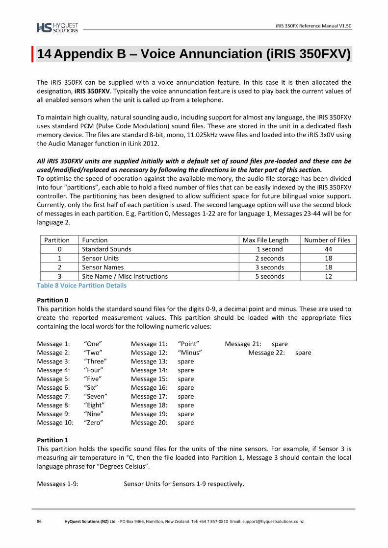
iRIS 350FX Reference Manual V1.50
86 HyQuest Solutions (NZ) Ltd - PO Box 9466, Hamilton, New Zealand Tel: +64 7 857-0810 Email: [email protected]
14 Appendix B – Voice Annunciation (iRIS 350FXV)
The iRIS 350FX can be supplied with a voice annunciation feature. In this case it is then allocated the designation, iRIS 350FXV. Typically the voice annunciation feature is used to play back the current values of all enabled sensors when the unit is called up from a telephone. To maintain high quality, natural sounding audio, including support for almost any language, the iRIS 350FXV uses standard PCM (Pulse Code Modulation) sound files. These are stored in the unit in a dedicated flash memory device. The files are standard 8-bit, mono, 11.025kHz wave files and loaded into the iRIS 3x0V using the Audio Manager function in iLink 2012. All iRIS 350FXV units are supplied initially with a default set of sound files pre-loaded and these can be used/modified/replaced as necessary by following the directions in the later part of this section. To optimise the speed of operation against the available memory, the audio file storage has been divided into four “partitions”, each able to hold a fixed number of files that can be easily indexed by the iRIS 350FXV controller. The partitioning has been designed to allow sufficient space for future bilingual voice support. Currently, only the first half of each partition is used. The second language option will use the second block of messages in each partition. E.g. Partition 0, Messages 1-22 are for language 1, Messages 23-44 will be for language 2.
Partition Function Max File Length Number of Files
0 Standard Sounds 1 second 44
1 Sensor Units 2 seconds 18
2 Sensor Names 3 seconds 18
3 Site Name / Misc Instructions 5 seconds 12
Table 8 Voice Partition Details
Partition 0 This partition holds the standard sound files for the digits 0-9, a decimal point and minus. These are used to create the reported measurement values. This partition should be loaded with the appropriate files containing the local words for the following numeric values: Message 1: “One” Message 11: “Point” Message 21: spare Message 2: “Two” Message 12: “Minus” Message 22: spare Message 3: “Three” Message 13: spare Message 4: “Four” Message 14: spare Message 5: “Five” Message 15: spare Message 6: “Six” Message 16: spare Message 7: “Seven” Message 17: spare Message 8: “Eight” Message 18: spare Message 9: “Nine” Message 19: spare Message 10: “Zero” Message 20: spare Partition 1 This partition holds the specific sound files for the units of the nine sensors. For example, if Sensor 3 is measuring air temperature in °C, then the file loaded into Partition 1, Message 3 should contain the local language phrase for “Degrees Celsius”. Messages 1-9: Sensor Units for Sensors 1-9 respectively.
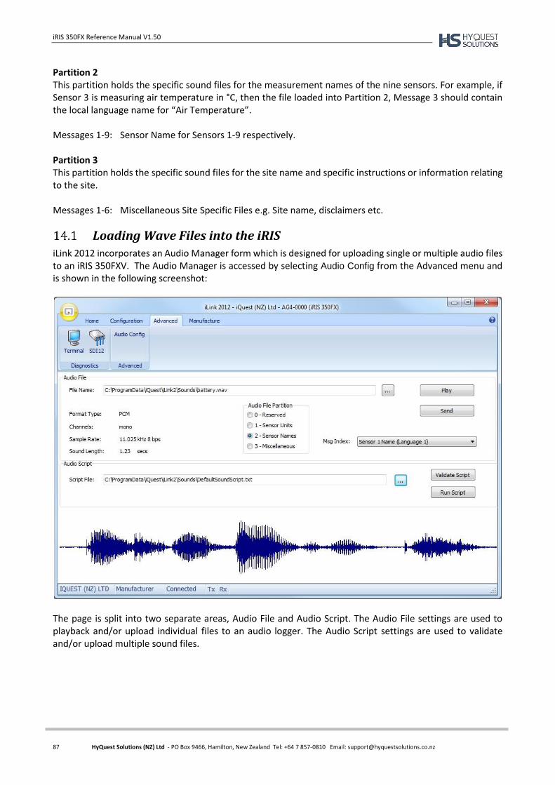
iRIS 350FX Reference Manual V1.50
87 HyQuest Solutions (NZ) Ltd - PO Box 9466, Hamilton, New Zealand Tel: +64 7 857-0810 Email: [email protected]
Partition 2 This partition holds the specific sound files for the measurement names of the nine sensors. For example, if Sensor 3 is measuring air temperature in °C, then the file loaded into Partition 2, Message 3 should contain the local language name for “Air Temperature”. Messages 1-9: Sensor Name for Sensors 1-9 respectively. Partition 3 This partition holds the specific sound files for the site name and specific instructions or information relating to the site. Messages 1-6: Miscellaneous Site Specific Files e.g. Site name, disclaimers etc.
Loading Wave Files into the iRIS
iLink 2012 incorporates an Audio Manager form which is designed for uploading single or multiple audio files to an iRIS 350FXV. The Audio Manager is accessed by selecting Audio Config from the Advanced menu and is shown in the following screenshot:
The page is split into two separate areas, Audio File and Audio Script. The Audio File settings are used to playback and/or upload individual files to an audio logger. The Audio Script settings are used to validate and/or upload multiple sound files.
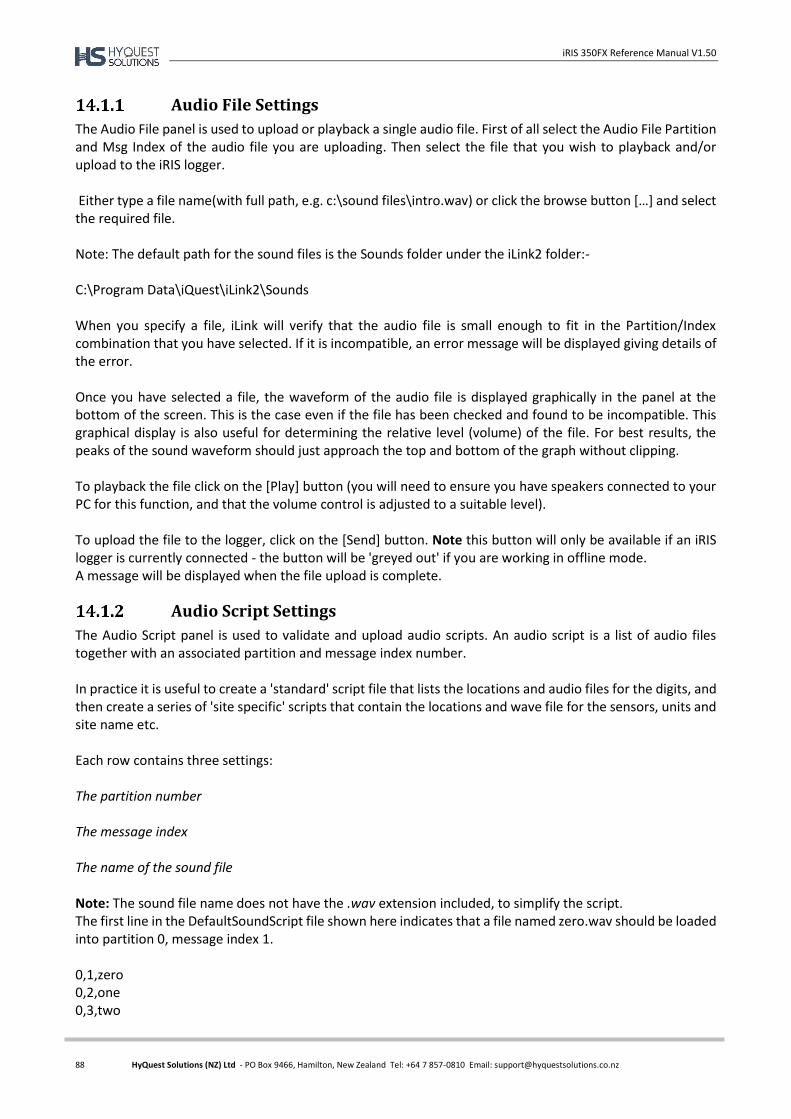
iRIS 350FX Reference Manual V1.50
88 HyQuest Solutions (NZ) Ltd - PO Box 9466, Hamilton, New Zealand Tel: +64 7 857-0810 Email: [email protected]
Audio File Settings
The Audio File panel is used to upload or playback a single audio file. First of all select the Audio File Partition and Msg Index of the audio file you are uploading. Then select the file that you wish to playback and/or upload to the iRIS logger. Either type a file name(with full path, e.g. c:\sound files\intro.wav) or click the browse button […] and select the required file. Note: The default path for the sound files is the Sounds folder under the iLink2 folder:- C:\Program Data\iQuest\iLink2\Sounds When you specify a file, iLink will verify that the audio file is small enough to fit in the Partition/Index combination that you have selected. If it is incompatible, an error message will be displayed giving details of the error. Once you have selected a file, the waveform of the audio file is displayed graphically in the panel at the bottom of the screen. This is the case even if the file has been checked and found to be incompatible. This graphical display is also useful for determining the relative level (volume) of the file. For best results, the peaks of the sound waveform should just approach the top and bottom of the graph without clipping. To playback the file click on the [Play] button (you will need to ensure you have speakers connected to your PC for this function, and that the volume control is adjusted to a suitable level). To upload the file to the logger, click on the [Send] button. Note this button will only be available if an iRIS logger is currently connected - the button will be 'greyed out' if you are working in offline mode. A message will be displayed when the file upload is complete.
Audio Script Settings
The Audio Script panel is used to validate and upload audio scripts. An audio script is a list of audio files together with an associated partition and message index number. In practice it is useful to create a 'standard' script file that lists the locations and audio files for the digits, and then create a series of 'site specific' scripts that contain the locations and wave file for the sensors, units and site name etc. Each row contains three settings: The partition number The message index The name of the sound file Note: The sound file name does not have the .wav extension included, to simplify the script. The first line in the DefaultSoundScript file shown here indicates that a file named zero.wav should be loaded into partition 0, message index 1. 0,1,zero 0,2,one 0,3,two

iRIS 350FX Reference Manual V1.50
89 HyQuest Solutions (NZ) Ltd - PO Box 9466, Hamilton, New Zealand Tel: +64 7 857-0810 Email: [email protected]
0,4,three 0,5,four 0,6,five 0,7,six 0,8,seven 0,9,eight 0,10,nine 0,11,point 0,12,minus 1,1,metres 1,2,degc 1,3,pause 1,4,pause 1,5,pause 1,6,pause 1,7,pause 1,8,pause 1,9,pause 1,10,pause 2,1,waterlevel 2,2,temperature All the sound files to be used in the script must be located in the C:\Program Data\iQuest\iLink2\Sounds folder. Validating Audio Script Files Once you have selected an audio script, you should click the [Validate Script] button to verify that the script dos not contain any errors. Possible errors might include syntax errors, the wrong number of parameters on a line, a wave file that does not exist, a wave file that is incompatible with the specified partition. As iLink2012 scans the script file, each of the specified wave files is selected into the Audio Panel (see earlier) and scanned for compatibility. The associated waveform is also displayed in the bottom panel as each file is processed. Once the verification process is complete, a message box will be displayed indicating either a successful scan, or the first error encountered. If an error is encountered, the details are displayed and will need to be corrected before the script can be run. Running an Audio Script File Once a script file has been selected and verified, click on the [Run Script] button to execute the script which will upload each of the specified audio files to the iRIS 350FXV. As each line of the script is processed, the top panel (Audio File Panel) reflects the current audio file, partition and index number, and the bottom panel displays the audio file waveform in a graphical format. When the script has completed, a message will be displayed confirming that the upload procedure is complete.

iRIS 350FX Reference Manual V1.50
90 HyQuest Solutions (NZ) Ltd - PO Box 9466, Hamilton, New Zealand Tel: +64 7 857-0810 Email: [email protected]
Uploading Audio Files over a Remote Connection
It is possible to upload audio files to an iRIS 350FXV that is connected to iLink 2012 over an IP or even a radio or other low-speed link. However due to the potentially large file sizes involved, it is highly recommended that all audio uploads are carried out with the logger connected directly to the PC via the RS232 port. Also, if communication to the logger is lost during a script-based audio upload, the results may be indeterminable as files may be only partially loaded so remote uploads should be carried out with caution and only considered where a local connection is absolutely not possible.
15 Appendix C – Using an iRIS-CAM Camera
Overview
The iRIS-CAM is a camera accessory for the iRIS 350FX datalogger. It is supplied in an environmentally sealed (IP66) enclosure constructed from a special corrosion-resistant aluminium alloy that is finished in a hard-anodised coating. This provides a very high degree of mechanical strength and EMI shielding, and enables completely stand-alone mounting in outdoor situations. The enclosure is filled with epoxy resin and the lens is silicon greased in place, which means the potential for water ingress is extremely low. When connected to an appropriately configured iRIS data logger, images can be taken, stored and then unloaded (at regular intervals) via any of the communication channels available to the iRIS (e.g. IP or RS232).
Specifications
SIZE: 162mm x 116mm x 65mm (4.60in x 6.37in x 2.64in) (WxHxD) CONNECTORS: 6 way rectangular connector on the end of 5m of shielded PVC cable. MASS: 300 g (10.6oz) POWER SUPPLY: 3.3V d.c +/- 10% (powered via cable from iRIS) RESOLUTION: Selectable 80x60, 160x128, 350x240 or 640x480 pixels, JPEG format, 24-bit colour STANDARD LENS: F2.8
Focal length 4mm Integral IR filter
ENVIRONMENTAL: Operating: -10 °C to +70 °C (14 °F to +158 °F) Storage: -10 °C to +85 °C (14 °F to +185 °F)
Enclosure sealed to IP66

iRIS 350FX Reference Manual V1.50
91 HyQuest Solutions (NZ) Ltd - PO Box 9466, Hamilton, New Zealand Tel: +64 7 857-0810 Email: [email protected]
Mounting
This can be achieved with the use of the four M6 Allen Key® bolts or other suitable hardware such as wood screws. The diagram below shows the overall dimensions and position of the mounting holes for the IRIS-CAM. The correct orientation is shown in the diagram, where the engraved writing is the right way up. The cable extends from the left side of the enclosure when viewing the camera from the front.
Due to the lens’s small aperture it can be susceptible to image quality degradation should a droplet of water land on the lens (the effect of which is to create a second lens, severely distorting the image). To minimize the effects of rain, provide the camera lens with a rain shield and position the camera so that it points down and away from prevailing weather.
Connecting the iRIS-CAM
Connecting the camera to the datalogger is a simple process. First disconnect all power to the logger then feed the camera cable through the gland. Next connect the iRIS-CAM 6 way connector to the camera port on the iRIS circuit board. This is located next to the SIM card carrier on the iRIS. Finally tighten the gland and re-power the logger.

iRIS 350FX Reference Manual V1.50
92 HyQuest Solutions (NZ) Ltd - PO Box 9466, Hamilton, New Zealand Tel: +64 7 857-0810 Email: [email protected]
The easiest way to commission the iRIS-CAM is to connect it to the USB port of a laptop or desktop PC. This allows quick and repetitive collection of images from the camera, enabling quick focusing and alignment of the camera. It is important to install the Windows® iRIS-CAM USB adapter drivers before connecting the camera to the PC.
Installing PC Based Software & USB Drivers
The following list of steps will install the iRIS-CAM commissioning software and the Windows® USB drivers for the iRIS-CAM adaptor.
1. Obtain the installation package from HyQuest Solutions.1
2. For the CD distribution:
a. Insert CD into PC’s CDROM drive. If the installer does not automatically start, then run it
manually from d:\ iRISCAMInstaller.exe (where d:\ is the CDROM drive letter).
b. Click on Install iRIS-CAM button and follow the prompts.
3. For a Web download:
a. Download the iRIS-CAM windows software installer package from
www.hyquestsolutions.co.nz
b. Run the iRISCAMInstaller.exe program and follow the instructions.
4. Once installation of the iRIS Camera Software is complete and the installation program has been
closed, install the USB drivers by:
a. Run the installer from Start->All Programs->iRIS-CAM->USB Driver Installer.
b. Click Install button.
If you are prompted with the message saying the software has not passed Windows Logo Verification, please ignore and click the Continue Anyway button.
1 Software can be obtained from CD or the HyQuest Solutions website: www.hyquestsolutions.co.nz
iRIS-CAM 6 way Connector on iRIS 350FX
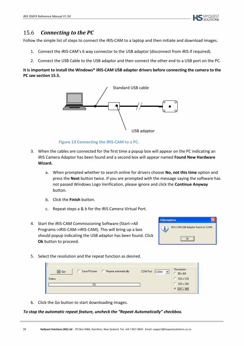
iRIS 350FX Reference Manual V1.50
93 HyQuest Solutions (NZ) Ltd - PO Box 9466, Hamilton, New Zealand Tel: +64 7 857-0810 Email: [email protected]
Connecting to the PC
Follow the simple list of steps to connect the iRIS-CAM to a laptop and then initiate and download images.
1. Connect the iRIS-CAM’s 6 way connector to the USB adaptor (disconnect from iRIS if required).
2. Connect the USB Cable to the USB adaptor and then connect the other end to a USB port on the PC.
It is important to install the Windows® iRIS-CAM USB adapter drivers before connecting the camera to the PC see section 15.5.
3. When the cables are connected for the first time a popup box will appear on the PC indicating an
iRIS Camera Adaptor has been found and a second box will appear named Found New Hardware
Wizard.
a. When prompted whether to search online for drivers choose No, not this time option and
press the Next button twice. If you are prompted with the message saying the software has
not passed Windows Logo Verification, please ignore and click the Continue Anyway
button.
b. Click the Finish button.
c. Repeat steps a & b for the iRIS Camera Virtual Port.
4. Start the iRIS-CAM Commissioning Software (Start->All
Programs->iRIS-CAM->iRIS-CAM). This will bring up a box
should popup indicating the USB adaptor has been found. Click
Ok button to proceed.
5. Select the resolution and the repeat function as desired.
6. Click the Go button to start downloading images.
To stop the automatic repeat feature, uncheck the “Repeat Automatically” checkbox.
USB adaptor
Standard USB cable
Figure 13 Connecting the iRIS-CAM to a PC.
iRIS 350FX Reference Manual V1.50
94 HyQuest Solutions (NZ) Ltd - PO Box 9466, Hamilton, New Zealand Tel: +64 7 857-0810 Email: [email protected]
Focusing
Focusing of the camera can be achieved by screwing the lens clockwise or anticlockwise when viewing the camera from the front. The camera is factory set to for midrange focus.
Anticlockwise rotation (or screw outwards) focuses on near objects.
Clockwise rotation (or screw inwards) focuses on distant objects.
iRIS Configuration
Once the camera has been installed and commissioned using the PC interface the iRIS needs to be programmed and configured.
Installing iRIS Software for Camera Support
Installation of iRIS datalogger based software is achieved by using the iLink software package on a PC connected to the logger via a null-modem cable. For details on how to upgrade the firmware and/or software lease refer to Error! Reference source not found.. The only requirement for camera support is to select the orrect version for Program Bank 2. This is the file with the identifier “Camera” instead of the standard variant which has the identifier “Std”. e.g. iRIS350FX_Cell(W)_Camera_zzz_2.350fx is the correct version for camera support on a Wavecom cellular version of the iRIS 350FX.
Configure the Camera on the iRIS
As with a standard iRIS data logger all configuration is achieved through iLink 2012 configuration menus. This is done by connecting a PC to the logger with a null modem cable and connecting to it with a terminal program like HyperTerminal. The list below describes the configuring of the settings that relate to the operation of the camera. Camera Menu The iRIS-CAM configuration is explained in Section 6.3.8. There are four ways of taking an image:
Scheduled – This method uses the Camera Schedule to take pictures at regular intervals. If external
illumination is required a digital output can be separately configured in schedule mode to power
the light source.
Alarm – If enabled, the camera will take a picture when the iRIS goes from having no active alarms
to one or more being active. To rearm this function, the alarms must return to normal, so this
works best when there is only a single alarm configured in the system.
Remote – Use HydroTel™ to start a picture capture. Refer to the HydroTel documentation on how
to setup and use this feature.
By a logged in user initiating a test call in from the communications LCD screen. This will take a
picture and automatically connect to the HydroTel base and have it retrieve the image(s).
Remote Picture Capture Settings In this mode the iRIS-CAM will take a picture on request from HydroTel™. There are no iRIS based settings required for this mode. Picture capture will happen automatically and can be used in conjunction with schedule mode. Resolution of the remotely requested picture can be different to ones taken by the scheduler, alarm or user.
iRIS 350FX Reference Manual V1.50
95 HyQuest Solutions (NZ) Ltd - PO Box 9466, Hamilton, New Zealand Tel: +64 7 857-0810 Email: [email protected]
16 Appendix D – Upgrading Firmware/Software
Overview
This section describes the procedure to use when upgrading the firmware/software components in an iRIS. The upgrade procedure has been carried out many times without issue. However, because the process does involve erasing and reprogramming of flash memory, it is important that a good, securely connected power supply is provided to the iRIS throughout the upgrade process.
File Naming Conventions
iRIS Executive Firmware
The “Firmware” in the iRIS is analogous to the operating system in a PC. It is the Firmware that contains all the low level functions and library routines used by the Application Software. The iRIS firmware is available as a single file for downloading and flash upgrading using iLink 2012. The upgrade file is in the format: iRIS350FX_Firmware_xxx.bin where: xxx is the firmware version e.g. iRIS350FX_Firmware_150.bin iRIS 350FX Firmware, Version Vx/1.50 The default repository for the firmware files is C:\ProgramData\iQuest\iLink2\Programs.
iRIS Application Software
The “Application Software” in the iRIS is analogous to an application such as Word® on a PC. It is the software that contains the general functionality of the iRIS. This comes in three sections or “banks” (due to the memory configuration of the iRIS) but runs as if it were one single program. The common software upgrade files for Banks 1, 2 and 3 are always in the format: iRIS350FX_xxxx_yyy_z.irx where: xxxx is the communication type (Cellular (Wavecom or Maxon), NoModem, Ethernet or Iridium). yyy is the software version
z is the program bank that this file should be loaded into e.g. iRIS350FX_Cellular_140_1.350fx iRIS 350FX Software, Cellular, Version 1.40, Bank 1 The default repository for the program files is the “Programs” folder under iLink.
iRIS 350FX Reference Manual V1.50
96 HyQuest Solutions (NZ) Ltd - PO Box 9466, Hamilton, New Zealand Tel: +64 7 857-0810 Email: [email protected]
Module OpenAT
The “OpenAT” in the Cellular Module is analogous to an application such as Word® on a PC. It is the software that controls the module's functions which are required by the iRIS 350FX for cellular communications. The OpenAT upgrade files are always in the format: iEmbedded_xxx_Vyyyy.dwl where: xxx is the module type (Q24 or Q26). yyyy is the OpenAT version. e.g. iEmbedded_Q24_V1_06.dwl Wavecom Q24 Software, Version 1.06 Upgrading the module's OpenAT can now be done through the Automated Upgrade Procedure along with the firmware and software. See the section below.
iRIS Automated Upgrade Procedure (Software/Firmware)
iLink 2012 has an automated firmware/software upgrade tool that supports the iRIS 350FX. This tool includes several checks to confirm the validity of the components being installed. The automated upgrade tool can do both the firmware and software upgrades in one process, saving considerable time and effort. The example given below shows a full, automatic firmware and software upgrade for an iRIS 350FX.
1. Make sure the required upgrade files are available on the computer. Ideally these should be
located in the default deployment folders listed above in Section 16.2.
2. Connect to the iRIS using iLink 2012.
3. Click on the Auto Upgrade button under the Configuration tab.
4. The iLink 2012 will automatically detect the variant and type of the device and these fields will be
populated with the appropriate configuration. If required, please select a different configuration
from the drop down list.
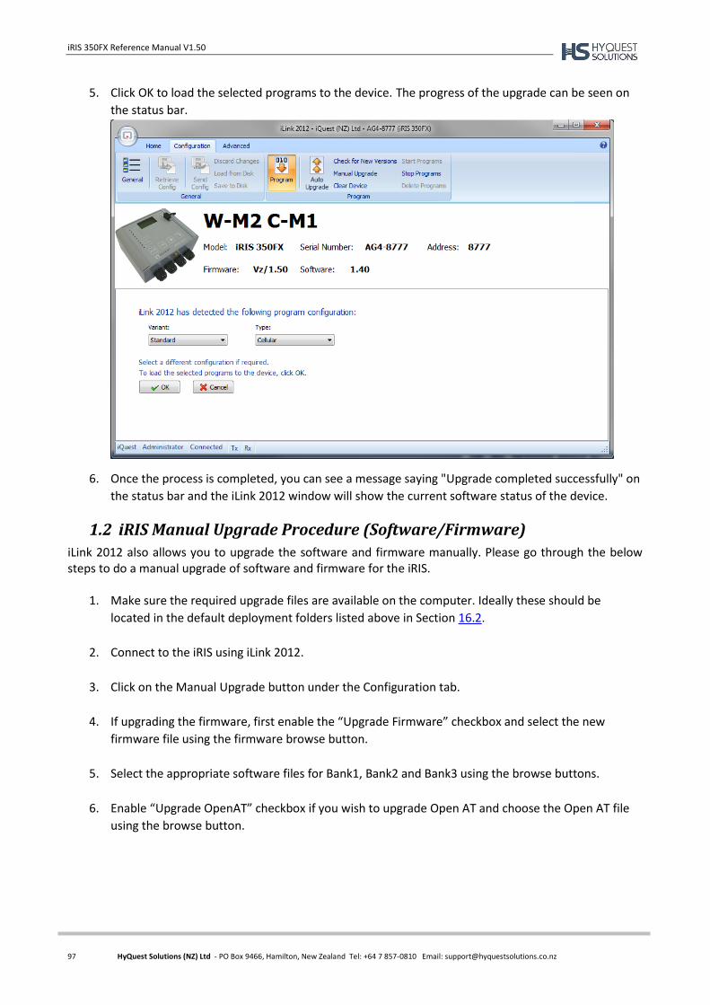
iRIS 350FX Reference Manual V1.50
97 HyQuest Solutions (NZ) Ltd - PO Box 9466, Hamilton, New Zealand Tel: +64 7 857-0810 Email: [email protected]
5. Click OK to load the selected programs to the device. The progress of the upgrade can be seen on
the status bar.
6. Once the process is completed, you can see a message saying "Upgrade completed successfully" on
the status bar and the iLink 2012 window will show the current software status of the device.
1.2 iRIS Manual Upgrade Procedure (Software/Firmware)
iLink 2012 also allows you to upgrade the software and firmware manually. Please go through the below steps to do a manual upgrade of software and firmware for the iRIS.
1. Make sure the required upgrade files are available on the computer. Ideally these should be
located in the default deployment folders listed above in Section 16.2.
2. Connect to the iRIS using iLink 2012.
3. Click on the Manual Upgrade button under the Configuration tab.
4. If upgrading the firmware, first enable the “Upgrade Firmware” checkbox and select the new
firmware file using the firmware browse button.
5. Select the appropriate software files for Bank1, Bank2 and Bank3 using the browse buttons.
6. Enable “Upgrade OpenAT” checkbox if you wish to upgrade Open AT and choose the Open AT file
using the browse button.
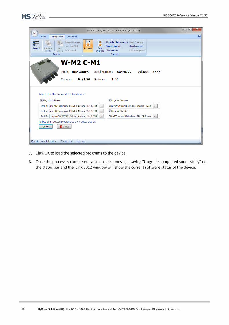
iRIS 350FX Reference Manual V1.50
98 HyQuest Solutions (NZ) Ltd - PO Box 9466, Hamilton, New Zealand Tel: +64 7 857-0810 Email: [email protected]
7. Click OK to load the selected programs to the device.
8. Once the process is completed, you can see a message saying "Upgrade completed successfully" on
the status bar and the iLink 2012 window will show the current software status of the device.

iRIS 350FX Reference Manual V1.50
99 HyQuest Solutions (NZ) Ltd - PO Box 9466, Hamilton, New Zealand Tel: +64 7 857-0810 Email: [email protected]
17 APPENDIX E – SDI-12
What is SDI-12?
SDI-12 stands for Serial Digital Interface at 1200 bps. It is a standard to interface battery powered data recorders with microprocessor-based sensors designed for environmental data acquisition (EDA). EDA is accomplished by means of a sensor, or sensors, and a data recorder, which collects and saves the data. SDI-12 is a standard communications protocol, which provides a means to transfer measurements taken by an intelligent sensor to a data recorder. An intelligent sensor typically takes a measurement, makes computations based on the raw sensor reading, and outputs the measured data in engineering units. For example, an SDI-12 pressure sensor may take a series of pressure measurements, average them, and then output pressure in psi, inches of mercury, bars, millibars, or torrs. The sensor's microprocessor makes the computations, converts sensor readings into the appropriate units, and uses the SDI-12 protocol to transfer data to the recorder. SDI-12 is a multi-drop interface that can communicate with multi-parameter sensors. Multi-drop means that more than one SDI-12 sensor can be connected to a data recorder. The SDI-12 bus is capable of having ten sensors connected to it. Having more than ten sensors, however, is possible. Some SDI-12 users connect more than ten sensors to a single data recorder. Multi-parameter means that a single sensor may return more than one measurement. For example, some water quality sensors return temperature, conductivity, dissolved oxygen, pH, turbidity, and depth.
Advantages of SDI-12
A serial-digital interface is a logical choice for interfacing microprocessor-based sensors with a data recorder. This has advantages for sensors and data recorders.
Unique and complex self-calibration algorithms can be done in microprocessor-based sensors.
Sensors can be interchanged without reprogramming the data recorder with calibration or other information.
Power is supplied to sensors through the interface.
Hybrid circuit and surface mount technologies make it practical to include the power supply regulator, a microprocessor, and other needed circuitry in small sensor packages.
Sensors can use low cost EEPROMs (electrically erasable programmable read only memory) for calibration coefficients and other information instead of internal trimming operations.
The use of a standard serial interface eliminates significant complexity in the design of data recorders.
Data recorders can be designed and produced independently of future sensor development.
SDI-12 data recorders interface with a variety of sensors.
SDI-12 sensors interface with a variety of data recorders.
Personnel trained in SDI-12 will have skills to work with a variety of SDI-12 data recorders and SDI-12 sensors.
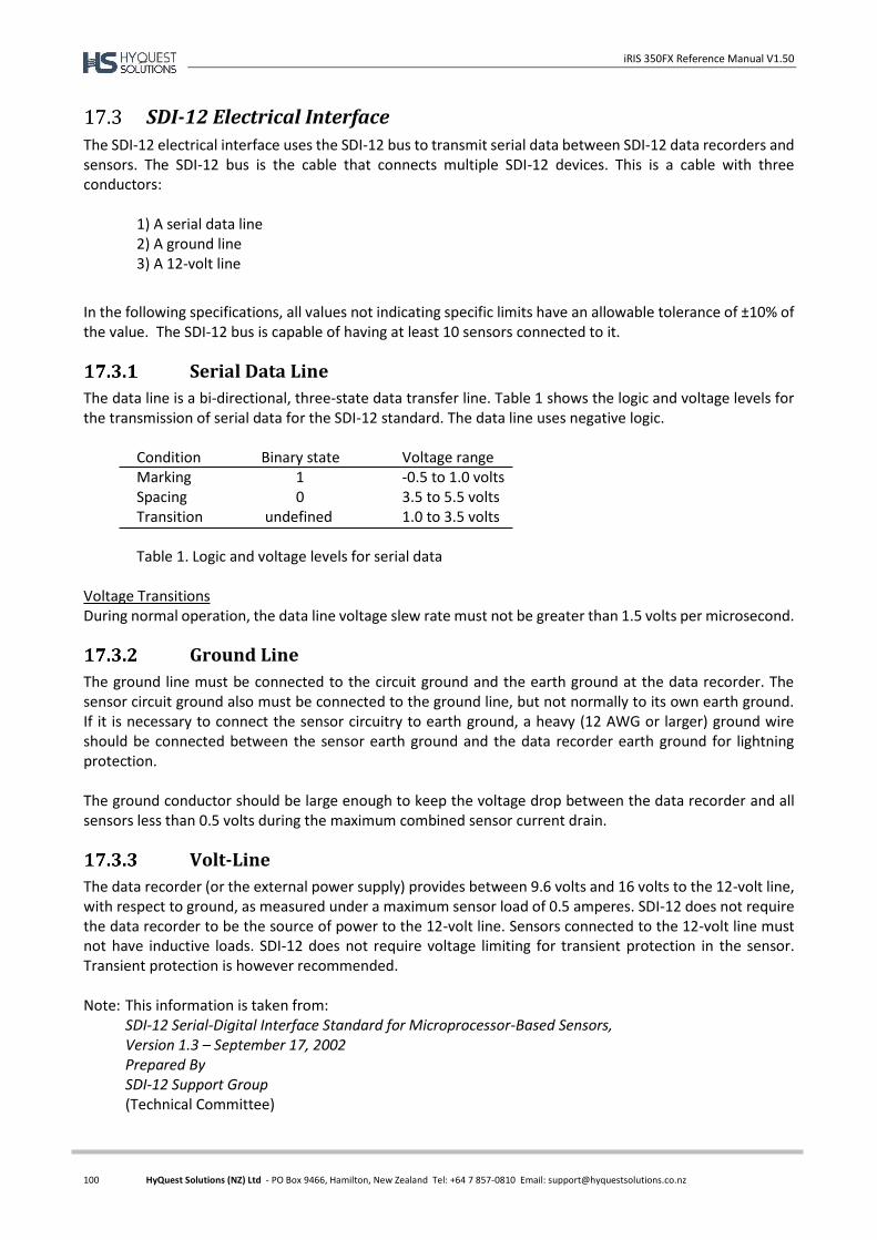
iRIS 350FX Reference Manual V1.50
100 HyQuest Solutions (NZ) Ltd - PO Box 9466, Hamilton, New Zealand Tel: +64 7 857-0810 Email: [email protected]
SDI-12 Electrical Interface
The SDI-12 electrical interface uses the SDI-12 bus to transmit serial data between SDI-12 data recorders and sensors. The SDI-12 bus is the cable that connects multiple SDI-12 devices. This is a cable with three conductors:
1) A serial data line 2) A ground line 3) A 12-volt line
In the following specifications, all values not indicating specific limits have an allowable tolerance of ±10% of the value. The SDI-12 bus is capable of having at least 10 sensors connected to it.
Serial Data Line
The data line is a bi-directional, three-state data transfer line. Table 1 shows the logic and voltage levels for the transmission of serial data for the SDI-12 standard. The data line uses negative logic.
Condition Binary state Voltage range Marking 1 -0.5 to 1.0 volts Spacing 0 3.5 to 5.5 volts Transition undefined 1.0 to 3.5 volts Table 1. Logic and voltage levels for serial data
Voltage Transitions During normal operation, the data line voltage slew rate must not be greater than 1.5 volts per microsecond.
Ground Line
The ground line must be connected to the circuit ground and the earth ground at the data recorder. The sensor circuit ground also must be connected to the ground line, but not normally to its own earth ground. If it is necessary to connect the sensor circuitry to earth ground, a heavy (12 AWG or larger) ground wire should be connected between the sensor earth ground and the data recorder earth ground for lightning protection. The ground conductor should be large enough to keep the voltage drop between the data recorder and all sensors less than 0.5 volts during the maximum combined sensor current drain.
Volt-Line
The data recorder (or the external power supply) provides between 9.6 volts and 16 volts to the 12-volt line, with respect to ground, as measured under a maximum sensor load of 0.5 amperes. SDI-12 does not require the data recorder to be the source of power to the 12-volt line. Sensors connected to the 12-volt line must not have inductive loads. SDI-12 does not require voltage limiting for transient protection in the sensor. Transient protection is however recommended. Note: This information is taken from:
SDI-12 Serial-Digital Interface Standard for Microprocessor-Based Sensors, Version 1.3 – September 17, 2002 Prepared By SDI-12 Support Group (Technical Committee)

iRIS 350FX Reference Manual V1.50
101 HyQuest Solutions (NZ) Ltd - PO Box 9466, Hamilton, New Zealand Tel: +64 7 857-0810 Email: [email protected]
18 User Notes