Embed Size (px)
Citation preview
BASICS OF HYDROGRAPHY & INSPECTION OF
SUBSEA INFRASTRUCTURES
Principles and Practice
1st Edition
The Manual of Surveyor
Geraud NAANKEU WATI
Positioning & Geomatic Specialist
BASICS OF HYDROGRAPHY & INSPECTION OF SUBSEA
INFRASTRUCTURES
Principles and Practice
1st Edition
The Manual of Surveyor
Author: Geraud NAANKEU WATI
ISBN: 979-10-699-3658-4
Cover designer: Editions Seng’a & LSD Creartion
Cover photo © Kosti Keistinen from Pixabay
First backward cover photo © Ricardo Resende from Unsplash
Second backwards cover photo © Riverbed survey data collected in Bulgaria with a Teledyne
RESON SeaBat T20-P multibeam echosounder and Teledyne PDS
Third backward cover photo © International Federation of Hydrographic Societies at Rostock-
Warnemünde in Germany, 2016
Copyright @Geraud NAANKEU WATI, 2019
All rights reserved.
No part of this book may be reproduced or utilized in any form or by any means, electronic or
mechanical, including photocopying, recording, or by any information storage and retrieval system,
without permission in writing by the copyright owner.
www.geraudnaankeuwati.com
3
CONTENTS
PREFACE ................................................................................................................................................... 11 CHAPTER 1. GENERAL INTRODUCTION. ........................................................................................ 19
1.1 What is Hydrography? ...................................................................................................... 20
1.2 What is Inspection of Subsea Infrastructures? ............................................................... 26
1.2.1 Inspection techniques ................................................................................................... 26
1.2.2 Sensors for investigating subsea infrastructures ........................................................... 27
1.3 Applications of Hydrography and Inspection of Subsea Infrastructures ..................... 28
1.3.1 Hydroelectric dam ........................................................................................................ 28
1.3.2 Lake .............................................................................................................................. 31
1.3.3 Rivers and channels...................................................................................................... 32
1.3.4 Coastal infrastructures and works of art ....................................................................... 33
1.3.5 Offshore oil and gas ..................................................................................................... 34
1.3.6 Civil and dredging works ............................................................................................. 38
1.3.7 Confined spaces ........................................................................................................... 39
1.3.8 National defense and security ...................................................................................... 39
1.3.9 Marine renewable energy ............................................................................................. 39
CHAPTER 2. SURVEY SYSTEMS. ........................................................................................................ 41 1.1 Surface Survey Systems .................................................................................................... 41
1.1.1 Traditional surface survey vessels ................................................................................ 41
1.1.2 Diving support vessels ................................................................................................. 43
1.1.3 Unmanned surface vessels ........................................................................................... 44
1.1.4 Hydro-oceanographic buoys ........................................................................................ 47
1.2 Underwater Survey Systems ............................................................................................. 48
1.2.1 Submersibles ................................................................................................................ 49
1.2.2 Remotely operated vehicles ......................................................................................... 50
1.2.3 Autonomous underwater vehicle .................................................................................. 53
CHAPTER 3. BASICS KNOWLEDGE OF HYDROGRAPHY AND INSPECTION OF SUBSEA
INFRASTRUCTURES. ............................................................................................................................. 57 1.1 Survey Project Management ............................................................................................ 58
1.2 Survey Team ...................................................................................................................... 61
1.3 Statistics .............................................................................................................................. 63
1.3.1 Mean ............................................................................................................................ 64
4
1.3.2 Standard deviation ........................................................................................................ 64
1.3.3 Median ......................................................................................................................... 64
1.3.4 Range ........................................................................................................................... 64
1.3.5 Expectation................................................................................................................... 64
1.3.6 Normal distribution ...................................................................................................... 64
1.3.7 Probability density ....................................................................................................... 65
1.4 Law of Uncertainty Propagation ...................................................................................... 65
1.5 Method of Least Squares .................................................................................................. 66
1.5.1 Linear least squares ...................................................................................................... 67
1.5.2 Non linear least squares ............................................................................................... 69
1.6 Trigonometry ..................................................................................................................... 70
1.6.1 Trigonometry in a rectangle triangle ............................................................................ 70
1.6.2 Trigonometry in a trigonometric circle ........................................................................ 71
1.7 Vectors ................................................................................................................................ 72
1.7.1 What is a vector? .......................................................................................................... 72
1.7.2 Operations on the vectors ............................................................................................. 72
1.8 Measurement of Lever Arms of Survey System ............................................................. 74
1.9 Datum ................................................................................................................................. 76
1.9.1 Types of datums ........................................................................................................... 76
1.9.2 Coordinate systems ...................................................................................................... 78
1.9.3 Reference ellipsoid ....................................................................................................... 83
1.9.4 Geoid ............................................................................................................................ 85
1.9.5 Coordinates transformations between two datums ....................................................... 85
1.10 Tide ................................................................................................................................... 88
1.10.1 Generalities ................................................................................................................ 88
1.10.2 Tidal cycles ................................................................................................................ 90
1.10.3 Tide prediction ........................................................................................................... 92
1.10.4 Analysis of tide data series for tide prediction ........................................................... 94
1.10.5 Determination of chart datum .................................................................................... 96
1.10.6 Tide gauge types ........................................................................................................ 98
1.11 Reference Frames and Transformations ..................................................................... 100
1.11.1 Terrestrial reference frame ....................................................................................... 100
1.11.2 Local geodetic frame or tangent frame ..................................................................... 101
5
1.11.3 Local navigation frame ............................................................................................ 102
1.11.4 Body frame ............................................................................................................... 103
1.11.5 Sensor frame ............................................................................................................ 104
1.12 Survey Software ............................................................................................................. 104
1.12.1 How to choose right software for surveying? ........................................................... 104
1.12.2 List of some survey software ................................................................................... 105
1.13 Computer Programming ............................................................................................... 109
CHAPTER 4. COMPUTERS AND INPUT/OUTPUT INTERFACES. ........................................... 113 1.1 Computers ........................................................................................................................ 113
1.1.1 Generalities ................................................................................................................ 113
1.1.2 Types of computers .................................................................................................... 114
1.2 Communication Interfaces.............................................................................................. 115
1.2.1 Serial links.................................................................................................................. 115
1.2.2 Registered Jack 45 (RJ45) connectors of 8 pins ......................................................... 123
1.2.3 BNC connectors ......................................................................................................... 127
1.2.4 Video connectors ........................................................................................................ 128
1.2.5 SubConn ..................................................................................................................... 130
CHAPTER 5. GLOBAL NAVIGATION SATELLITES SYSTEM. .................................................... 131 1.1 Description of Global Navigation Satellites System (GNSS) ........................................ 131
1.1.1 GNSS architecture ...................................................................................................... 132
1.1.2 Basic principle of GNSS positioning ......................................................................... 135
1.1.3 GNSS error sources .................................................................................................... 137
1.1.4 GNSS positioning modes ........................................................................................... 138
1.1.5 GNSS positioning methods ........................................................................................ 139
1.1.6 Satellite based augmentation system (SBAS) ............................................................ 142
1.2 What is a GNSS Positioning System? ............................................................................ 144
1.2.1 Specifications of GNSS positioning system ............................................................... 144
1.2.2 Output data in MNEA standard .................................................................................. 151
1.2.3 Requirements for installation a GNSS antenna .......................................................... 155
CHAPTER 6. INTRODUCTION TO UNDERWATER ACOUSTICS. ............................................ 159 1.1 Acoustic Waves ................................................................................................................ 159
1.2 Characteristics of the Marine Environment ................................................................. 161
1.2.1 Ambient noise ............................................................................................................ 162
6
1.2.2 Absorption coefficient of sea water............................................................................ 163
1.2.3 Sound velocity in the sea water .................................................................................. 164
1.2.4 Surface reverberation ................................................................................................. 168
1.2.5 Background reverberation .......................................................................................... 169
1.3 Modeling of acoustic signal path in the sea water ......................................................... 169
1.4 Modeling of Water Height measured by a Depth Sensor ............................................. 171
1.4.1 Computation algorithms of physical properties of sea water ..................................... 172
1.4.2 Estimation of the water height ................................................................................... 174
CHAPTER 7. SUBSEA ACOUSTIC POSITIONING SYSTEMS. ..................................................... 177 1.1 USBL Positioning System ............................................................................................... 178
1.1.1 USBL positioning system in transponder mode ......................................................... 179
1.1.2 USBL positioning system in responder mode ............................................................ 184
1.1.3 Advantages and disadvantages of USBL acoustic positioning system ...................... 186
1.2 LBL Positioning System .................................................................................................. 186
1.3 SBL Positioning System .................................................................................................. 189
1.4 Doppler Velocity Log ...................................................................................................... 190
1.5 Correlation Velocity Log ................................................................................................ 195
CHAPTER 8. INERTIAL NAVIGATION SYSTEM. .......................................................................... 199 1.1 Description of Inertial Navigation System .................................................................... 200
1.1.1 Configurations of INSs .............................................................................................. 200
1.1.2 Classification of inertial sensors ................................................................................ 202
1.1.3 Inertial sensor errors ................................................................................................... 202
1.1.4 The bias of sensor....................................................................................................... 203
1.1.5 The white noise of sensor ........................................................................................... 204
1.1.6 The rate random walk of sensor ................................................................................. 204
1.1.7 Specifications of inertial measurement unit ............................................................... 206
1.2 Inertial Navigation Equations ........................................................................................ 208
1.2.1 Attitude equation ........................................................................................................ 209
1.2.2 Velocity equation ....................................................................................................... 211
1.2.3 Position equation ........................................................................................................ 212
1.3 Inertial Navigation Error Equations ............................................................................. 213
1.3.1 Attitude error equation ............................................................................................... 213
1.3.2 Velocity error equation .............................................................................................. 214
7
1.3.3 Position error equation ............................................................................................... 215
1.4 Aided Inertial Navigation System for Subsea Operations ........................................... 216
1.4.1 Kalman filter .............................................................................................................. 217
1.4.2 Kalman filter algorithm for states estimation of INS coupled with external sensors . 219
1.4.3 Correction stage ......................................................................................................... 222
CHAPTER 9. SWATH MAPPING SYSTEMS. ................................................................................... 225 1.1 Multibeam Echosounder ................................................................................................. 226
1.1.1 General presentation of multibeam echosounder ....................................................... 226
1.1.2 Electronic architecture of a multibeam echosounder ................................................. 228
1.1.3 Working principle of a multibeam echosounder ........................................................ 229
1.1.4 Description of MBES‟s technical specifications ........................................................ 230
1.1.5 Assembly diagram of MBES acquisition system ....................................................... 242
1.1.6 MBES survey methodology ....................................................................................... 246
1.2 Side Scan Sonar ............................................................................................................... 255
1.2.1 General presentation of side scan sonar ..................................................................... 255
1.2.2 Electronic hardware of a side scan sonar ................................................................... 256
1.2.3 Working principle of a side scan sonar ...................................................................... 257
1.2.4 Technical specifications of side scan sonar ................................................................ 259
1.2.5 Types of side scan sonars ........................................................................................... 263
1.2.6 Deployment of side scan sonar ................................................................................... 266
1.2.7 Advantages and disadvantages of side scan sonar ..................................................... 267
1.2.8 SSS survey methodology ........................................................................................... 267
1.2.9 Post-processing of side scan sonar images ................................................................. 270
1.2.10 Interpretation of side scan sonar images .................................................................. 272
CHAPTER 10. SYSTEMS FOR INSPECTION OF SUBSEA INFRASTRUCTURES. .................. 275 1.1 2D Acoustic Camera ........................................................................................................ 276
1.1.1 General presentation of 2D acoustic camera .............................................................. 276
1.1.2 Working principle of 2D acoustic camera .................................................................. 277
1.1.3 Description of technical specifications of 2D acoustic camera .................................. 278
1.1.4 Deployment of 2D acoustic cameras .......................................................................... 283
1.1.5 Survey methodology via 2D acoustic camera ............................................................ 285
1.1.6 Processing of 2D acoustic images .............................................................................. 287
1.1.7 Interpretation of images from 2D acoustic cameras ................................................... 288
8
1.2 Digital video Camera ....................................................................................................... 288
1.2.1 General presentation of digital video camera ............................................................. 289
1.2.2 Working principle of digital video camera ................................................................. 291
1.2.3 Architecture of acquisition system by digital video camera ....................................... 292
1.2.4 Technical specifications of digital video camera ....................................................... 293
1.2.5 Types of digital video cameras used for inspection operations .................................. 295
1.2.6 Recording video in file from video stream ................................................................. 297
1.2.7 Video bitrate ............................................................................................................... 298
1.3 3D Laser Scanner ............................................................................................................ 298
1.3.1 General presentation of 3D laser scanner ................................................................... 298
1.3.2 Applications of 3D laser scanners .............................................................................. 299
1.3.3 Principle working of a 3D laser scanner .................................................................... 300
1.3.4 3D laser scanner types ................................................................................................ 302
1.3.5 Electronic architecture of a 3D laser scanner acquisition system............................... 304
1.3.6 Technical specifications of 3D laser scanners ............................................................ 306
1.3.7 Survey methodology of 3D laser scanner ................................................................... 308
CHAPTER 11. SYSTEMS FOR GEOPHYSICAL SURVEYS. ........................................................... 311 1.1 Sub-Bottom Profiler ........................................................................................................ 311
1.1.1 Electronic hardware of a sub-bottom profiler ............................................................ 312
1.1.2 Working principle of a sub-bottom profiler ............................................................... 313
1.1.3 Types of sub-bottom profilers .................................................................................... 315
1.1.4 Deployment of sub-bottom profilers .......................................................................... 319
1.1.5 Acquisition and processing of data from sub-bottom profilers .................................. 322
1.1.6 Interpretation of images from sub-bottom profilers ................................................... 322
CHAPTER 12. ANALYSIS OF ERROR BUDGET FOR MULTIBEAM SURVEY SYSTEMS ..... 325 1.1 Importance of Error budget Analysis for a MBES survey System ............................. 326
1.1.1 Types of measurement uncertainties in MBES survey system ................................... 327
1.1.2 Identification of measurement error sources of hydrographic survey system ............ 328
1.2 Geo-Referencing Equations of Sounding Acquired by a Surface Survey System ...... 331
1.2.1 Geometric description of a surface multi beam survey system .................................. 331
1.2.2 Geo-referencing equations of sounding in the navigation frame ................................ 331
1.2.3 Sounding reduction for MBES surface survey system ............................................... 336
1.3 Geo-Referencing Equations of Sounding Acquired by a Subsea Survey System ....... 342

9
1.3.1 General principle of data fusion ................................................................................. 344
1.3.2 Equations of a sounding position expressed in the navigation frame ......................... 344
1.3.3 Sounding reduction .................................................................................................... 345
1.4 Error Budget Estimation for Hydrographic Survey Systems ...................................... 347
1.4.1 Algorithm of error budget estimation for surface survey system ............................... 347
1.4.2 Algorithm of error budget estimation of subsea survey system ................................. 349
GLOSSARY ............................................................................................................................................... 351 BIBLIOGRAPHY..................................................................................................................................... 355

10
“This book reflects my desire to share my knowledge and experience of the field with you”
Geraud NAANKEU WATI
11
PREFACE
My name is Geraud NAANKEU WATI, positioning and geomatic specialist. In 2015, I obtained
a Master‟s degree in Hydrography and Oceanography at ENSTA Bretagne, with knowledge in
management, mathematics, computer science and robotics. For the past five years, I have worked
on several survey campaigns and research and development projects in hydrography and subsea
infrastructure inspection such as:
- Error budget analysis of underwater and surface survey systems,
- Trajectory computation of an autonomous underwater vehicle (AUV) from an inertial
navigation system (INS) coupled with a Doppler velocity log (DVL) and an Ultra Short
BaseLine (USBL) positioning system,
- Positioning of a subsea vehicle in opened and confined underwater environments
(tunnels, galleries, etc…),
- Tide prediction from tidal observations,
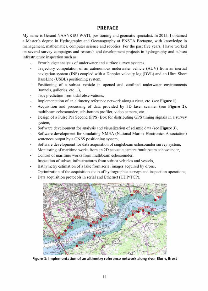
- Implementation of an altimetry reference network along a river, etc. (see Figure 1)
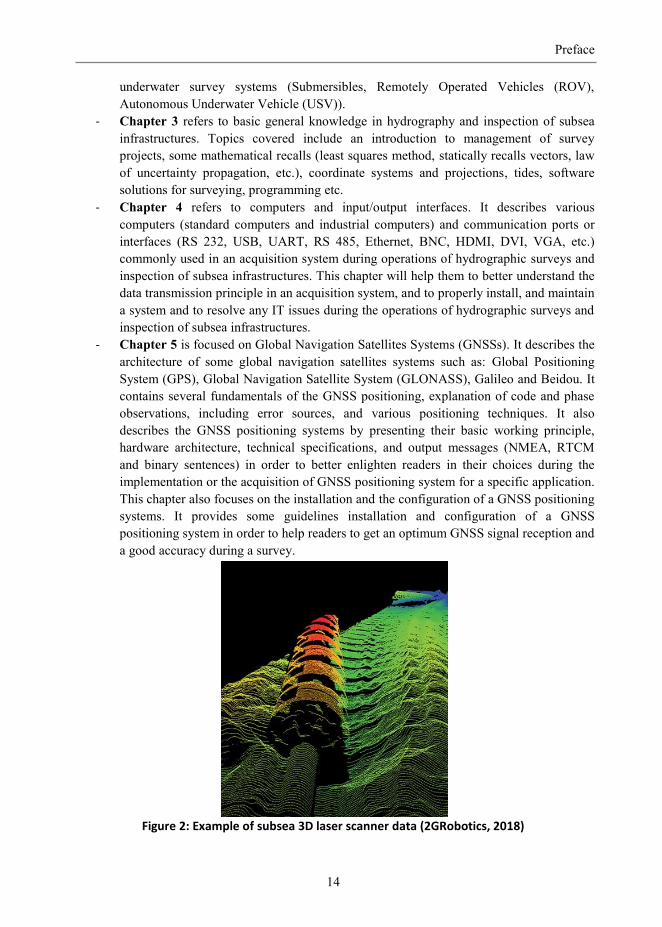
- Acquisition and processing of data provided by 3D laser scanner (see Figure 2),
multibeam echosounder, sub-bottom profiler, video camera, etc…
- Design of a Pulse Per Second (PPS) Box for distributing GPS timing signals in a survey
system,
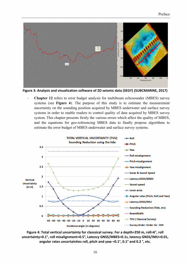
- Software development for analysis and visualization of seismic data (see Figure 3),
- Software development for simulating NMEA (National Marine Electronics Association)
sentences output by a GNSS positioning system,
- Software development for data acquisition of singlebeam echosounder survey system,
- Monitoring of maritime works from an 2D acoustic camera /multibeam echosounder,
- Control of maritime works from multibeam echosounder,
- Inspection of subsea infrastructures from subsea vehicles and vessels,
- Bathymetry estimation of a lake from aerial images acquired by drone,
- Optimization of the acquisition chain of hydrographic surveys and inspection operations,
- Data acquisition protocols in serial and Ethernet (UDP/TCP).
Figure 1: Implementation of an altimetry reference network along river Elorn, Brest
Preface
12
During these different projects, I learned a lot of new things and encountered several issues such
as:
- Properly implement a software of coordinate transformation,
- Properly implement a multibeam echosounder acquisition system,
- Understand and correct various time errors in a data acquisition system,
- Manage a survey project (survey constraints will vary depending on whether the project
is performed on smaller water bodies (rivers, lakes, channels) or on larger ones such as
oceans and seas.
- Properly calibrate a multibeam echosounder and 3D laser scanner acquisition systems,
- Implement an inertial navigation system on a remotely operated vehicle (ROV),
- Choosing the right surveying software solutions,
- Managing large volumes of data in various formats (LAS, LAZ, MP4, etc.), etc.
I started out as Junior Surveyor. Due to the lack of field experience and solid basics in
hydrography and subsea infrastructure inspection, I usually spent so much time these above
mentioned issues. For instance:
- My first field experience was to work as data processor offshore on a vessel where all
equipments were already installed and calibrated.
- Moreover, I really didn‟t understand the working principles of some sensors (USBL,
DVL, CVL, etc.), protocols of data transfer, time stamping, time servers, etc.
- Neither, did I understand the general field constraints just like most young surveyors,
- I had however a good generalist training in management, mathematics, computer science
and robotics, which allowed me to quickly adapt to new situations.
In addition, I usually spent several hours to perform repetitive operations in the office. As I don‟t
like losing time, I often developed small software to automate long processes and to optimize the
processing time of data (navigation, multibeam, videos, etc.).
From time to time, I attended conferences to have an exchange with other professionals of the
hydrographic community on themes and issues affecting several areas of our activity. During my
exchanges, I noticed that some hydrographic surveyors were not aware of some aspects such as:
the non-necessity to use a heave sensor for hydrographic sounding reduction using a separation
model between the chart datum and the ellipsoid reference (Sanders, RTK Tides without a heave
sensor, 2015). They carried out multibeam surveys without understanding the theory of sounding
geo-referencing. I also noticed that some hydrographic surveyors as I was spent several hours to
process and merge multibeam data; while it was often enough to reverse one attitude
measurement or to do a good calibration process in order to properly merge data and save time.
After spending much time to resolve several issues in hydrography and inspection of subsea
infrastructures, I understood that it is important for professionals and also stakeholders to have a
good knowledge of these fields for ensuring the success of projects linked to those ones. Then, I
decided to write this book for four main reasons:
1. To share my knowledge and experience of the field in positioning, hydrography and
inspection of subsea infrastructures with stakeholders, and the members of hydrographic
and topographic communities (teachers, students, surveyors, survey engineers,
managers, institutes, etc.)
Preface
13
2. To contribute to the training of surveyors, and to help them to overcome numerous
issues and to meet the needs in hydrography and inspection of subsea infrastructures in
the world,
3. To help the stakeholders to specify their internal standards and to evaluate the technical
aspects of contractor proposals, in order to get high accurate data,
4. To initiate people without theoretical and practical knowledge in hydrography and
inspection of subsea infrastructures and to promote these fields.
This book has several purposes:
- It provides an introduction to hydrography and inspection of subsea infrastructures,
- It describes the various sensors used in survey projects (role, applications, working
principle, technical specifications, output, etc.),
- It describes various communication connectors and protocols used in a survey system,
- It presents some basic notions in management, mathematics, electronics, oceanography
and geodesy necessary in hydrography and inspection of subsea infrastructures,
- It provides an introduction to tide prediction and to determination of a chart datum,
- It provides algorithms for geo-referencing in data (multibeam, 3D scanner laser, etc.),
- It describes the principles of operation of GNSS satellites, inertial systems, and many
other navigation technologies, both qualitatively and mathematically,
- It provides an introduction to underwater acoustics, and timing in survey systems,
- It provides an introduction to error budget analysis of survey systems, etc…
According to Frédéric GUILLOT, CEO at SUBCMARINE: The new book: “Basics of
Hydrographic and Inspection of Subsea Infrastructures – Principles and Practice” is very
useful for students and professionals in topography, hydrography and inspection of subsea
infrastructures (surveyors, survey engineers, scientists, etc.). They will learn many theoretical and
practical basics about GNSS, acoustic and inertial positioning systems, 3D laser scanner systems,
sub-bottom profilers, multibeam echosounders, 2D acoustic cameras and methods for geo-
referencing, calibrating system and data analysis. Experts or specialists in hydrography and
inspection of subsea infrastructures could learn something new such as concrete/practical
solutions to better manage a survey project, to efficiently install survey system, and to optimize
survey operations in terms of time and quality. Stakeholders, chief surveyors, experts and CEOs
could find some good solutions such as: how to build a successful survey team? How to choose
(acquisition, processing, visualization, etc.)? How to estimate the error budget of acquisition
system? This book is also useful for hydrographic professionals involved with emerging national
hydrographic offices wishing to comply with the International Hydrographic Organization (IHO)
standards. This book can then be considered to be a manual for surveyors.
The layout of this book is divided into 12 chapters:
- Chapter 1: This book begins with brief definition of hydrography and inspection of
subsea infrastructures in presenting surveys various applications of hydrography and
inspection of subsea infrastructures (nautical charting, port and coastal management,
offshore engineering). It also presents types of hydrographic and inspection surveys and
some constraints commonly encountered in these applications.
- Chapter 2 presents the various types of survey systems commonly used for
hydrographic and inspection operations namely: surface survey systems (traditional
survey vessels, Diving support vessels, unmanned surface vehicles, buoys, etc.) and
Preface
14
underwater survey systems (Submersibles, Remotely Operated Vehicles (ROV),
Autonomous Underwater Vehicle (USV)).
- Chapter 3 refers to basic general knowledge in hydrography and inspection of subsea
infrastructures. Topics covered include an introduction to management of survey
projects, some mathematical recalls (least squares method, statically recalls vectors, law
of uncertainty propagation, etc.), coordinate systems and projections, tides, software
solutions for surveying, programming etc.
- Chapter 4 refers to computers and input/output interfaces. It describes various
computers (standard computers and industrial computers) and communication ports or
interfaces (RS 232, USB, UART, RS 485, Ethernet, BNC, HDMI, DVI, VGA, etc.)
commonly used in an acquisition system during operations of hydrographic surveys and
inspection of subsea infrastructures. This chapter will help them to better understand the
data transmission principle in an acquisition system, and to properly install, and maintain
a system and to resolve any IT issues during the operations of hydrographic surveys and
inspection of subsea infrastructures.
- Chapter 5 is focused on Global Navigation Satellites Systems (GNSSs). It describes the
architecture of some global navigation satellites systems such as: Global Positioning
System (GPS), Global Navigation Satellite System (GLONASS), Galileo and Beidou. It
contains several fundamentals of the GNSS positioning, explanation of code and phase
observations, including error sources, and various positioning techniques. It also
describes the GNSS positioning systems by presenting their basic working principle,
hardware architecture, technical specifications, and output messages (NMEA, RTCM
and binary sentences) in order to better enlighten readers in their choices during the
implementation or the acquisition of GNSS positioning system for a specific application.
This chapter also focuses on the installation and the configuration of a GNSS positioning
systems. It provides some guidelines installation and configuration of a GNSS
positioning system in order to help readers to get an optimum GNSS signal reception and
a good accuracy during a survey.
Figure 2: Example of subsea 3D laser scanner data (2GRobotics, 2018)
Preface
15
- Chapter 6 introduces to underwater acoustics. It presents the basic knowledge of
underwater acoustics in order to help readers to understand the properties of acoustic
wave, the specificities of subsea environment, the working principle of the acoustic
sensors and the main parameters which affect the propagation of acoustic waves in the
water.
- Chapter 7 is focused on the subsea acoustic positioning systems. It describes subsea
acoustic positioning systems commonly used for subsea operations: Ultra Short
BaseLine (USBL), Long BaseLine (LBL) and Short BaseLine (SBL) positioning
systems, Doppler Velocity Log (DVL) and Correlation Velocity Log (CVL). A
particular attention is focused on their working principles, accuracies, applications and
implementations on survey platforms in order to help readers to better manage
operations of hydrographic surveys and inspection of subsea infrastructures.
- Chapter 8 refers to inertial navigation system. It provides an introduction to inertial
navigation to help readers to better understand the working principle of the inertial
navigation systems, to know the various errors which characterize the inertial navigation
systems, and to properly choose, deploy and use an inertial navigation system during
survey operations.
- Chapter 9 is focused on swath bathymetry survey systems. The aim of this chapter is to
describe in depth the swath-mapping systems (multibeam echosounder and side scan
sonar), the most used for mapping of subsea environment in order to help readers to
better manage mapping projects. It presents the architecture, implementation, technical
specifications of swath mapping systems and also the survey methodology for swath-
mapping systems (mobilization, quality control, calibration, acquisition and processing
of data, deliverables, etc.).
- Chapter 10 is focused on systems suitable for operations of subsea infrastructures
inspection (docks, channels, bridges, dams, subsea infrastructures, etc.). The purpose of
this chapter is to describe in depth the systems commonly used for investigating the
emerged and immersed parts of coastal and subsea infrastructures in order to help
readers to better manage operations of subsea infrastructures inspection and ensure the
monitoring and the durability of infrastructures.
- Chapter 11 is devoted to sub-bottom profilers. It is to present various sub-bottom
profilers which are commonly used for geophysical surveys such as chirp, pinger,
parametric, boomer and sparker sub-bottom profilers. It describes briefly their
characteristics, applications, working principles, and also their survey methodologies
(installation, acquisition, processing and interpretation of seismic data).
Preface
16
Figure 3: Analysis and visualization software of 2D seismic data (SEGY) (SUBCMARINE, 2017)
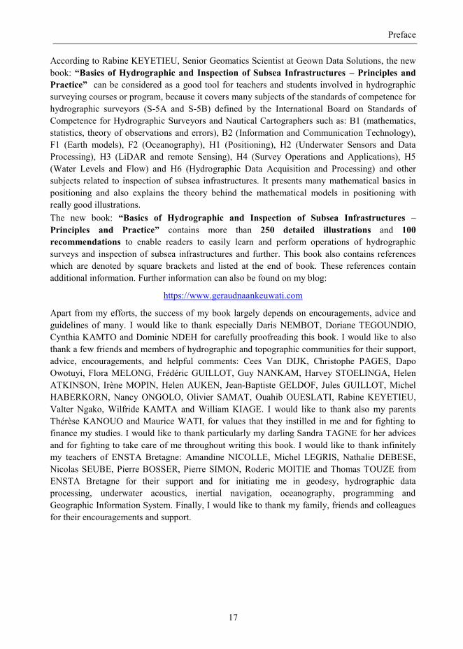
- Chapter 12 refers to error budget analysis for multibeam echosounder (MBES) survey
systems (see Figure 4). The purpose of this study is to estimate the measurement
uncertainty on the sounding position acquired by MBES underwater and surface survey
systems in order to enable readers to control quality of data acquired by MBES survey
system. This chapter presents firstly the various errors which affect the quality of MBES,
and the equations for geo-referencing MBES data to finally propose algorithms to
estimate the error budget of MBES underwater and surface survey systems.
Figure 4: Total vertical uncertainty for classsical survey. For a depth=250 m, roll=6°, roll
uncertainty=0.1°, roll misalignment=0.5°, Latency GNSS/MBES=0.1s, latency GNSS/IMU=0.01, angular rates uncertainties roll, pitch and yaw =0.1°, 0.1° and 0.2 °, etc.
Preface
17
According to Rabine KEYETIEU, Senior Geomatics Scientist at Geown Data Solutions, the new
book: “Basics of Hydrographic and Inspection of Subsea Infrastructures – Principles and
Practice” can be considered as a good tool for teachers and students involved in hydrographic
surveying courses or program, because it covers many subjects of the standards of competence for
hydrographic surveyors (S-5A and S-5B) defined by the International Board on Standards of
Competence for Hydrographic Surveyors and Nautical Cartographers such as: B1 (mathematics,
statistics, theory of observations and errors), B2 (Information and Communication Technology),
F1 (Earth models), F2 (Oceanography), H1 (Positioning), H2 (Underwater Sensors and Data
Processing), H3 (LiDAR and remote Sensing), H4 (Survey Operations and Applications), H5
(Water Levels and Flow) and H6 (Hydrographic Data Acquisition and Processing) and other
subjects related to inspection of subsea infrastructures. It presents many mathematical basics in
positioning and also explains the theory behind the mathematical models in positioning with
really good illustrations.
The new book: “Basics of Hydrographic and Inspection of Subsea Infrastructures –
Principles and Practice” contains more than 250 detailed illustrations and 100
recommendations to enable readers to easily learn and perform operations of hydrographic
surveys and inspection of subsea infrastructures and further. This book also contains references
which are denoted by square brackets and listed at the end of book. These references contain
additional information. Further information can also be found on my blog:
https://www.geraudnaankeuwati.com
Apart from my efforts, the success of my book largely depends on encouragements, advice and
guidelines of many. I would like to thank especially Daris NEMBOT, Doriane TEGOUNDIO,
Cynthia KAMTO and Dominic NDEH for carefully proofreading this book. I would like to also
thank a few friends and members of hydrographic and topographic communities for their support,
advice, encouragements, and helpful comments: Cees Van DIJK, Christophe PAGES, Dapo
Owotuyi, Flora MELONG, Frédéric GUILLOT, Guy NANKAM, Harvey STOELINGA, Helen
ATKINSON, Irène MOPIN, Helen AUKEN, Jean-Baptiste GELDOF, Jules GUILLOT, Michel
HABERKORN, Nancy ONGOLO, Olivier SAMAT, Ouahib OUESLATI, Rabine KEYETIEU,
Valter Ngako, Wilfride KAMTA and William KIAGE. I would like to thank also my parents
Thérèse KANOUO and Maurice WATI, for values that they instilled in me and for fighting to
finance my studies. I would like to thank particularly my darling Sandra TAGNE for her advices
and for fighting to take care of me throughout writing this book. I would like to thank infinitely
my teachers of ENSTA Bretagne: Amandine NICOLLE, Michel LEGRIS, Nathalie DEBESE,
Nicolas SEUBE, Pierre BOSSER, Pierre SIMON, Roderic MOITIE and Thomas TOUZE from
ENSTA Bretagne for their support and for initiating me in geodesy, hydrographic data
processing, underwater acoustics, inertial navigation, oceanography, programming and
Geographic Information System. Finally, I would like to thank my family, friends and colleagues
for their encouragements and support.

18
"Practice without theory is blind, Theory without practice is sterile”
Emmanuel KANT
19
CHAPTER 1.
GENERAL INTRODUCTION
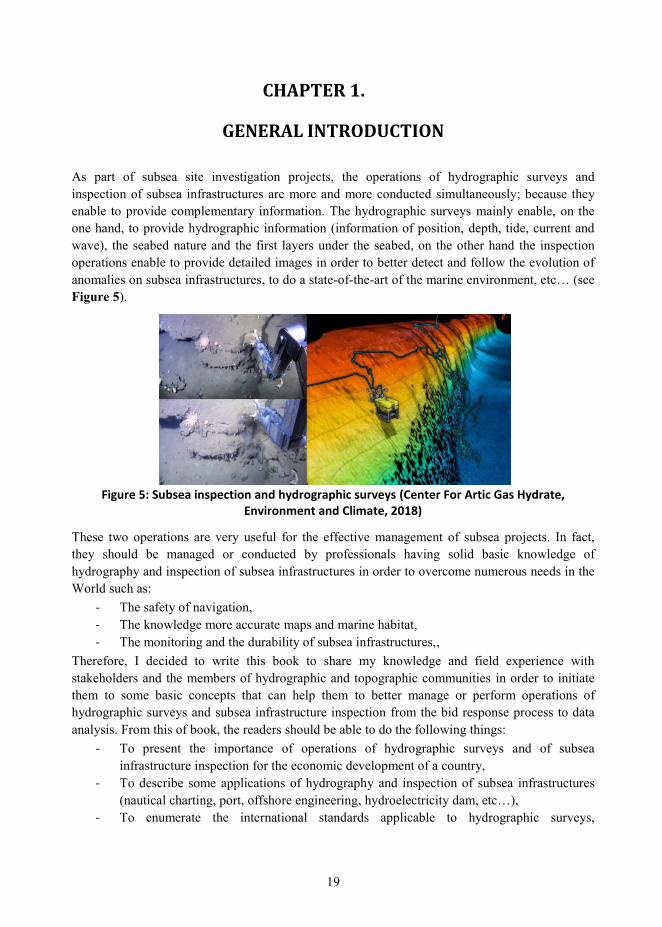
As part of subsea site investigation projects, the operations of hydrographic surveys and
inspection of subsea infrastructures are more and more conducted simultaneously; because they
enable to provide complementary information. The hydrographic surveys mainly enable, on the
one hand, to provide hydrographic information (information of position, depth, tide, current and
wave), the seabed nature and the first layers under the seabed, on the other hand the inspection
operations enable to provide detailed images in order to better detect and follow the evolution of
anomalies on subsea infrastructures, to do a state-of-the-art of the marine environment, etc… (see
Figure 5).
Figure 5: Subsea inspection and hydrographic surveys (Center For Artic Gas Hydrate,
Environment and Climate, 2018)
These two operations are very useful for the effective management of subsea projects. In fact,
they should be managed or conducted by professionals having solid basic knowledge of
hydrography and inspection of subsea infrastructures in order to overcome numerous needs in the
World such as:
- The safety of navigation,
- The knowledge more accurate maps and marine habitat,
- The monitoring and the durability of subsea infrastructures,,
Therefore, I decided to write this book to share my knowledge and field experience with
stakeholders and the members of hydrographic and topographic communities in order to initiate
them to some basic concepts that can help them to better manage or perform operations of
hydrographic surveys and subsea infrastructure inspection from the bid response process to data
analysis. From this of book, the readers should be able to do the following things:
- To present the importance of operations of hydrographic surveys and of subsea
infrastructure inspection for the economic development of a country,
- To describe some applications of hydrography and inspection of subsea infrastructures
(nautical charting, port, offshore engineering, hydroelectricity dam, etc…),
- To enumerate the international standards applicable to hydrographic surveys,
Chapter 1. General introduction
20
- To manage and perform the hydrographic surveys and inspection inspections,
- To create a successful survey department,
- To choose right software solutions for a survey company or a survey project,
- To setup and use subsea acoustic and GNSS positioning systems,
- To setup and use a tide gauge and explain the tide theory,
- To describe the concepts behind hydrographic survey systems and ancillary sensors,
- To control and assess the quality of survey data,
- To state the concepts and methods of survey data processing and acquisition,
- To install, configure, and calibrate an acquisition system for operations of hydrographic
surveys and inspection of subsea infrastructures,
- To analyze hydrographic data, point cloud, acoustic and optical images,
- To promote hydrography and inspection of subsea infrastructures in the world, etc.
I will introduce the first chapter of the book by presenting briefly the fields of hydrography and
subsea infrastructure inspection. This first chapter is divided into 3 sections. In the Section 1.1, I
will define the notion of hydrography and present some techniques of hydrographic surveys. In
the Section 1.2, I will define the notion of subsea infrastructure inspection and, I will present the
importance of inspection for the monitoring and the durability of subsea infrastructures, and also
some sensors commonly used for investigating subsea infrastructures. In the Section 1.3, I will
describe some applications of hydrography and subsea infrastructure inspection such as:
hydroelectricity dam, oil and gas, civil and dredging works, coastal infrastructures, confined
spaces, etc…
1.1 WHAT IS HYDROGRAPHY?
The International Hydrographic Organization (IHO) defined Hydrography as a branch of applied
sciences which deals with the measurement and description of the physical features of oceans,
seas, coastal areas, lakes and rivers, as well as with the prediction of their change over time, for
the primary purpose of safety of navigation. In addition to supporting safe and efficient
navigation, hydrography serves as support in most of inlands, coastal and offshore activities,
including: maritime transport and navigation, hydroelectricity power, defense and security,
offshore oil and gas, subsea renewable energy, infrastructures and works of art, archeology,
aquaculture, environmental works, civil works and dredging and galleries.
1.1.1 Hydrographic survey techniques As part of inlands, coastal and offshore projects, the hydrographic companies or hydrographic
offices are commonly solicited to produce marine information such as: bathymetry, geophysical,
tidal and seismic information. This information is very important to ensure the safety of
operations and navigation, to plan future repair works, etc... They are obtained through the
following survey techniques, namely:
- Hydrographic surveys by echosounder,
- Geophysical surveys,
- Positioning,
- Tide prediction and support operations.
Chapter 1. General introduction
21
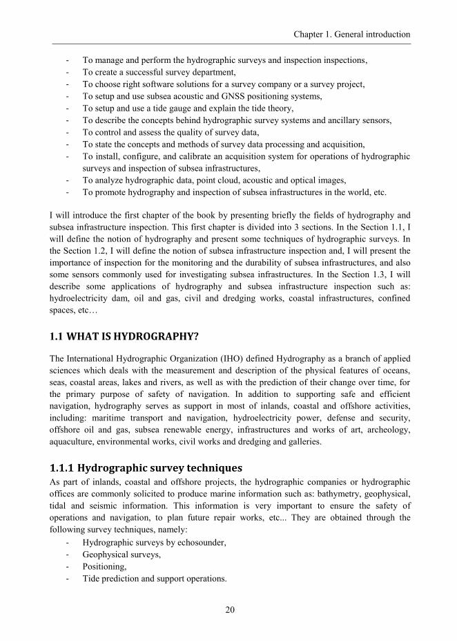
1.1.1.1 Hydrographic surveys by echosounder
A Hydrographic survey by echosounder is a survey technique which consists of describing
physical features of seabed for primarily the safety of navigation of vessels and military
submersibles (see Figure 6) based on determining the travel time of acoustic signal emits from an
echosounder. When the purpose of the survey by echosounder is not to guarantee the security of
navigation, it is usually called bathymetry survey. A bathymetric survey is however performed to
determine the depth, know the morphology of the seabed, verify the position of existing subsea
installations, detect anomalies and scouring areas on the civil engineering of subsea
infrastructures, etc…
Figure 6: Hydrographic surveys performed to ensure the safety of navigation in Panama canal
(Panama Canal Authority)
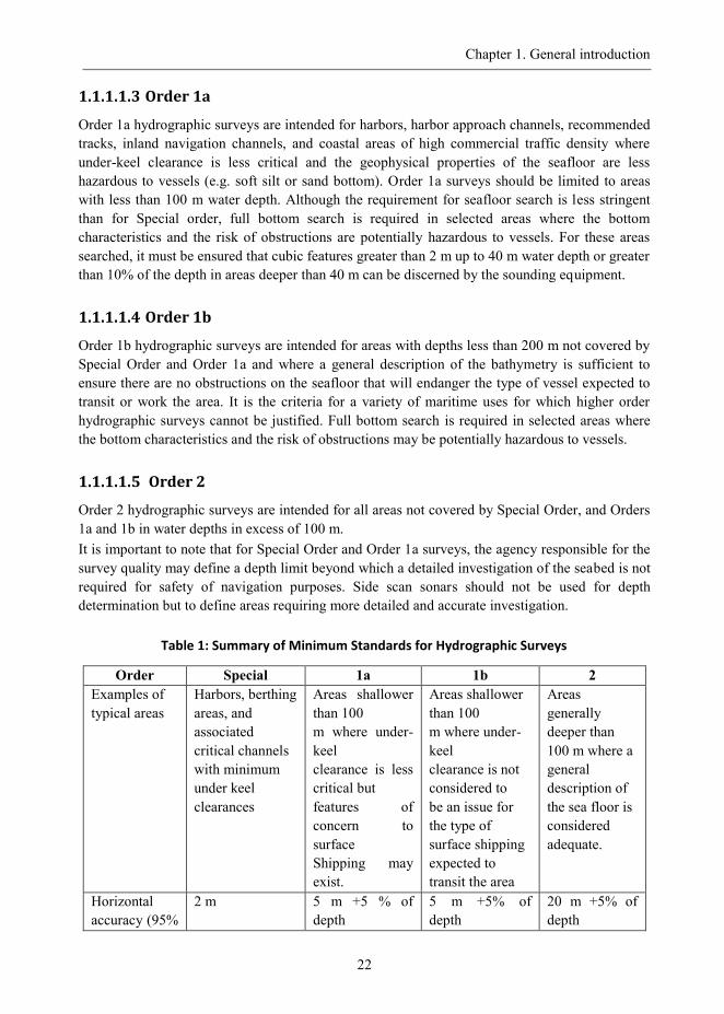
1.1.1.1.1 Classification of hydrographic surveys
To accommodate in a systematic manner different accuracy requirements for areas to be
surveyed, four orders of survey have been defined by the IHO S44. These are described at Table
1 below which summarizes the overall requirements that are in fact the essence of the complete
standard.
1.1.1.1.2 Special order
Special order hydrographic surveys are intended to be restricted to specific critical areas with
minimum under-keel clearance and where bottom characteristics are potentially hazardous to
vessels. These areas have to be explicitly designated by the agency responsible for survey quality
(harbors, berthing areas, and associated critical channels. All error sources which affected the
accuracy of sounding measurement should be minimized or cancelled.
The use of side scan sonar, or multi transducer arrays, or high-resolution multibeam echo
sounders is required to detect the feature size to be detected. In required areas, appropriate
sounding equipment and methodologies must be employed in order to ensure that all features
greater than 1m cubed are detected. The use of side scan sonar in conjunction with multibeam or
multi-transducer echo sounders may be necessary in areas where pinnacles and dangerous
obstacles may be encountered.
Chapter 1. General introduction
22
1.1.1.1.3 Order 1a
Order 1a hydrographic surveys are intended for harbors, harbor approach channels, recommended
tracks, inland navigation channels, and coastal areas of high commercial traffic density where
under-keel clearance is less critical and the geophysical properties of the seafloor are less
hazardous to vessels (e.g. soft silt or sand bottom). Order 1a surveys should be limited to areas
with less than 100 m water depth. Although the requirement for seafloor search is less stringent
than for Special order, full bottom search is required in selected areas where the bottom
characteristics and the risk of obstructions are potentially hazardous to vessels. For these areas
searched, it must be ensured that cubic features greater than 2 m up to 40 m water depth or greater
than 10% of the depth in areas deeper than 40 m can be discerned by the sounding equipment.
1.1.1.1.4 Order 1b
Order 1b hydrographic surveys are intended for areas with depths less than 200 m not covered by
Special Order and Order 1a and where a general description of the bathymetry is sufficient to
ensure there are no obstructions on the seafloor that will endanger the type of vessel expected to
transit or work the area. It is the criteria for a variety of maritime uses for which higher order
hydrographic surveys cannot be justified. Full bottom search is required in selected areas where
the bottom characteristics and the risk of obstructions may be potentially hazardous to vessels.
1.1.1.1.5 Order 2
Order 2 hydrographic surveys are intended for all areas not covered by Special Order, and Orders
1a and 1b in water depths in excess of 100 m.
It is important to note that for Special Order and Order 1a surveys, the agency responsible for the
survey quality may define a depth limit beyond which a detailed investigation of the seabed is not
required for safety of navigation purposes. Side scan sonars should not be used for depth
determination but to define areas requiring more detailed and accurate investigation.
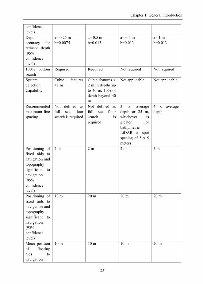
Table 1: Summary of Minimum Standards for Hydrographic Surveys
Order Special 1a 1b 2
Examples of
typical areas
Harbors, berthing
areas, and
associated
critical channels
with minimum
under keel
clearances
Areas shallower
than 100
m where under-
keel
clearance is less
critical but
features of
concern to
surface
Shipping may
exist.
Areas shallower
than 100
m where under-
keel
clearance is not
considered to
be an issue for
the type of
surface shipping
expected to
transit the area
Areas
generally
deeper than
100 m where a
general
description of
the sea floor is
considered
adequate.
Horizontal
accuracy (95%
2 m 5 m +5 % of
depth
5 m +5% of
depth
20 m +5% of
depth
Chapter 1. General introduction
23
confidence
level)
Depth
accuracy for
reduced depth
(95%
confidence
level)
a= 0.25 m
b=0.0075
a= 0.5 m
b=0.013
a= 0.5 m
b=0.013
a= 1 m
b=0.013
100% bottom
search
Required Required Not required Not required
System
detection
Capability
Cubic features
>1 m
Cubic features >
2 m in depths up
to 40 m; 10% of
depth beyond 40
m
Not applicable Not applicable
Recommended
maximum line
spacing
Not defined as
full sea floor
search is required
Not defined as
full sea floor
search is
required
3 x average
depth or 25 m,
whichever is
greater. For
bathymetric
LiDAR a spot
spacing of 5 x 5
meters
4 x average
depth
Positioning of
fixed aids to
navigation and
topography
significant to
navigation
(95%
confidence
level)
2 m 2 m 2 m 5 m
Positioning of
fixed aids to
navigation and
topography
significant to
navigation
(95%
confidence
level)
10 m 20 m 20 m 20 m
Mean position
of floating
aids to
navigation
10 m 10 m 10 m 20 m
Chapter 1. General introduction
24
(95%
confidence
level)
The limits for total vertical uncertainty (TVU) or (depth accuracy of sounding) at 95% is function
of parameters „a‟ and „b‟ listed in table above with the depth „d‟ have to be introduced into the
formula as below:
𝑇𝑉𝑈 = ± 𝑎2 + 𝑏 ∗ 𝑑 2
Where:
- a represents that portion of the uncertainty which doesn‟t vary with the depth
- b is a coefficient which represents that uncertainty portion that varies with the depth,
- d is the depth.
- b*d corresponds to the portion of the uncertainty that varies with the depth.
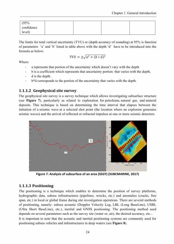
1.1.1.2 Geophysical site survey
The geophysical site survey is a survey technique which allows investigating subsurface structure
(see Figure 7), particularly as related to exploration for petroleum, natural gas, and mineral
deposits. This technique is based on determining the time interval that elapses between the
initiation of a seismic wave at a selected shot point (the location where an explosion generates
seismic waves) and the arrival of reflected or refracted impulses at one or more seismic detectors.
Figure 7: Analysis of subsurface of an area (SEGY) (SUBCMARINE, 2017)
1.1.1.3 Positioning
The positioning is a technique which enables to determine the position of survey platforms,
hydrographic data, subsea infrastructures (pipelines, wrecks, etc.) and anomalies (cracks, free
span, etc.) in local or global frame during site investigation operations. There are several methods
of positioning, namely: subsea acoustic (Doppler Velocity Log, LBL (Long BaseLine), USBL
(Ultra Short BaseLine), etc.), inertial and GNSS positioning. The positioning method used
depends on several parameters such as the survey site (water or, air), the desired accuracy, etc...
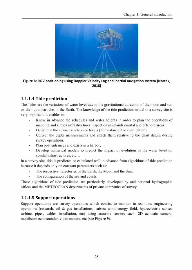
It is important to note that the acoustic and inertial positioning systems are commonly used for
positioning subsea vehicles and infrastructures in deep waters (see Figure 8).
Chapter 1. General introduction
25
Figure 8: ROV positioning using Doppler Velocity Log and inertial navigation system (Nortek,
2018)
1.1.1.4 Tide prediction
The Tides are the variations of water level due to the gravitational attraction of the moon and sun
on the liquid particles of the Earth. The knowledge of the tide prediction model in a survey site is
very important; it enables to:
- Know in advance the schedules and water heights in order to plan the operations of
mapping and subsea infrastructures inspection in inlands coastal and offshore areas.
- Determine the altimetry reference levels ( for instance: the chart datum),
- Correct the depth measurements and attach them relative to the chart datum during
survey operations,
- Plan boat entrances and exists in a harbor,
- Develop numerical models to predict the impact of evolution of the water level on
coastal infrastructures, etc…
In a survey site, tide is predicted or calculated well in advance from algorithms of tide prediction
because it depends only on constant parameters such as:
- The respective trajectories of the Earth, the Moon and the Sun,
- The configuration of the sea and coasts.
These algorithms of tide prediction are particularly developed by and national hydrographic
offices and the METEOCEAN departments of private companies of survey.
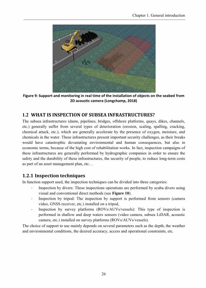
1.1.1.5 Support operations
Support operations are survey operations which consist to monitor in real time engineering
operations (research, oil & gas installations, subsea wind energy field, hydroelectric subsea
turbine, pipes, cables installation, etc) using acoustic sensors such: 2D acoustic camera,
multibeam echosounder, video camera, etc (see Figure 9).
Chapter 1. General introduction
26
Figure 9: Support and monitoring in real time of the installation of objects on the seabed from
2D acoustic camera (Longchamp, 2018)
1.2 WHAT IS INSPECTION OF SUBSEA INFRASTRUCTURES? The subsea infrastructures (dams, pipelines, bridges, offshore platforms, quays, dikes, channels,
etc.) generally suffer from several types of deterioration (erosion, scaling, spalling, cracking,
chemical attack, etc.), which are generally accelerate by the presence of oxygen, moisture, and
chemicals in the water. These infrastructures present important security challenges, as their breaks
would have catastrophic devastating environmental and human consequences, but also in
economic terms, because of the high cost of rehabilitation works. In fact, inspection campaigns of
these infrastructures are generally performed by hydrographic companies in order to ensure the
safety and the durability of these infrastructures, the security of people, to reduce long-term costs
as part of an asset management plan, etc…
1.2.1 Inspection techniques In function support used, the inspection techniques can be divided into three categories:
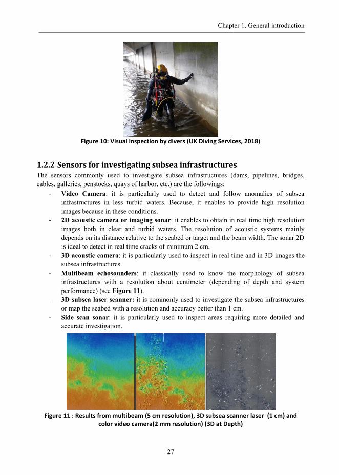
- Inspection by divers: These inspections operations are performed by scuba divers using
visual and conventional direct methods (see Figure 10).
- Inspection by tripod: The inspection by support is performed from sensors (camera
video, GNSS receiver, etc.) installed on a tripod,
- Inspection by survey platforms (ROVs/AUVs/vessels): This type of inspection is
performed in shallow and deep waters sensors (video camera, subsea LiDAR, acoustic
camera, etc.) installed on survey platforms (ROVs/AUVs/vessels).
The choice of support to use mainly depends on several parameters such as the depth, the weather
and environmental conditions, the desired accuracy, access and operational constraints, etc.
Chapter 1. General introduction
27
Figure 10: Visual inspection by divers (UK Diving Services, 2018)
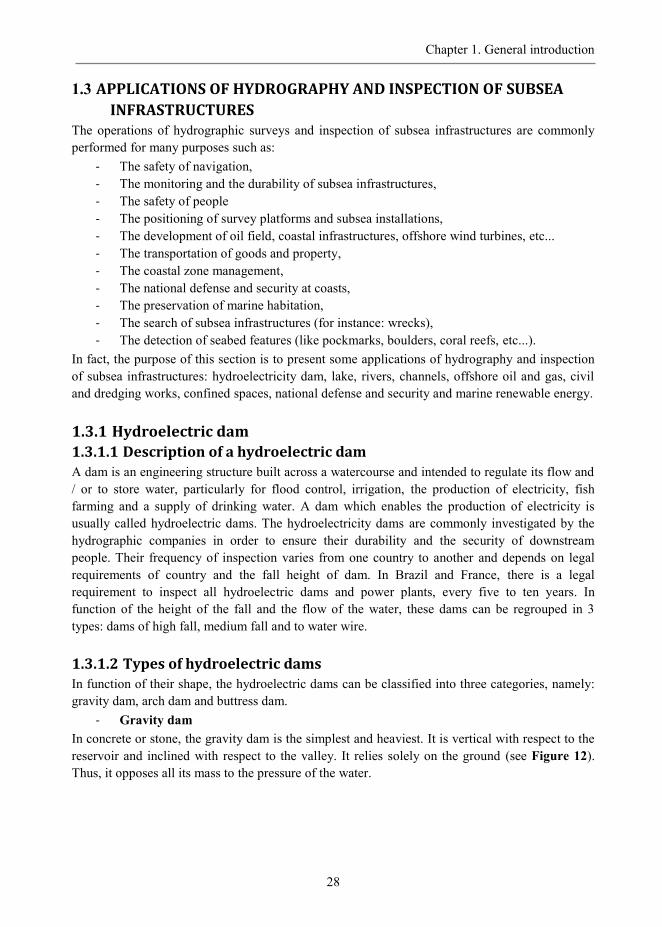
1.2.2 Sensors for investigating subsea infrastructures The sensors commonly used to investigate subsea infrastructures (dams, pipelines, bridges,
cables, galleries, penstocks, quays of harbor, etc.) are the followings:
- Video Camera: it is particularly used to detect and follow anomalies of subsea
infrastructures in less turbid waters. Because, it enables to provide high resolution
images because in these conditions.
- 2D acoustic camera or imaging sonar: it enables to obtain in real time high resolution
images both in clear and turbid waters. The resolution of acoustic systems mainly
depends on its distance relative to the seabed or target and the beam width. The sonar 2D
is ideal to detect in real time cracks of minimum 2 cm.
- 3D acoustic camera: it is particularly used to inspect in real time and in 3D images the
subsea infrastructures.
- Multibeam echosounders: it classically used to know the morphology of subsea
infrastructures with a resolution about centimeter (depending of depth and system
performance) (see Figure 11).
- 3D subsea laser scanner: it is commonly used to investigate the subsea infrastructures
or map the seabed with a resolution and accuracy better than 1 cm.
- Side scan sonar: it is particularly used to inspect areas requiring more detailed and
accurate investigation.
Figure 11 : Results from multibeam (5 cm resolution), 3D subsea scanner laser (1 cm) and
color video camera(2 mm resolution) (3D at Depth)
Chapter 1. General introduction
28
1.3 APPLICATIONS OF HYDROGRAPHY AND INSPECTION OF SUBSEA
INFRASTRUCTURES The operations of hydrographic surveys and inspection of subsea infrastructures are commonly
performed for many purposes such as:
- The safety of navigation,
- The monitoring and the durability of subsea infrastructures,
- The safety of people
- The positioning of survey platforms and subsea installations,
- The development of oil field, coastal infrastructures, offshore wind turbines, etc...
- The transportation of goods and property,
- The coastal zone management,
- The national defense and security at coasts,
- The preservation of marine habitation,
- The search of subsea infrastructures (for instance: wrecks),
- The detection of seabed features (like pockmarks, boulders, coral reefs, etc...).
In fact, the purpose of this section is to present some applications of hydrography and inspection
of subsea infrastructures: hydroelectricity dam, lake, rivers, channels, offshore oil and gas, civil
and dredging works, confined spaces, national defense and security and marine renewable energy.
1.3.1 Hydroelectric dam
1.3.1.1 Description of a hydroelectric dam
A dam is an engineering structure built across a watercourse and intended to regulate its flow and
/ or to store water, particularly for flood control, irrigation, the production of electricity, fish
farming and a supply of drinking water. A dam which enables the production of electricity is
usually called hydroelectric dams. The hydroelectricity dams are commonly investigated by the
hydrographic companies in order to ensure their durability and the security of downstream
people. Their frequency of inspection varies from one country to another and depends on legal
requirements of country and the fall height of dam. In Brazil and France, there is a legal
requirement to inspect all hydroelectric dams and power plants, every five to ten years. In
function of the height of the fall and the flow of the water, these dams can be regrouped in 3
types: dams of high fall, medium fall and to water wire.
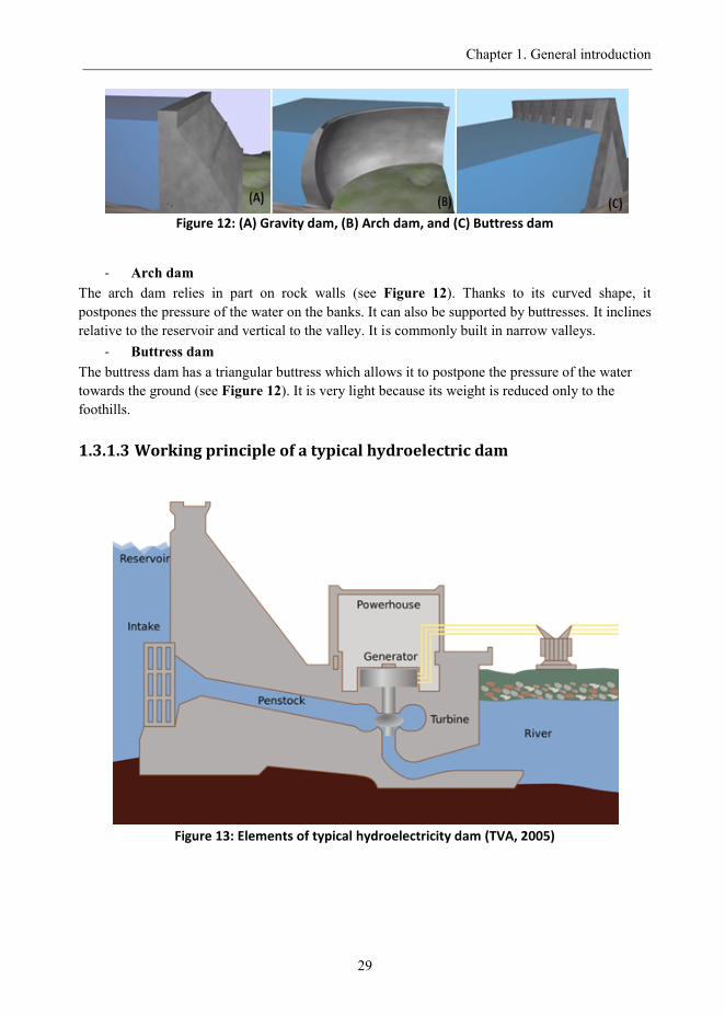
1.3.1.2 Types of hydroelectric dams
In function of their shape, the hydroelectric dams can be classified into three categories, namely:
gravity dam, arch dam and buttress dam.
- Gravity dam
In concrete or stone, the gravity dam is the simplest and heaviest. It is vertical with respect to the
reservoir and inclined with respect to the valley. It relies solely on the ground (see Figure 12).
Thus, it opposes all its mass to the pressure of the water.
Chapter 1. General introduction
29
Figure 12: (A) Gravity dam, (B) Arch dam, and (C) Buttress dam
- Arch dam
The arch dam relies in part on rock walls (see Figure 12). Thanks to its curved shape, it
postpones the pressure of the water on the banks. It can also be supported by buttresses. It inclines
relative to the reservoir and vertical to the valley. It is commonly built in narrow valleys.
- Buttress dam
The buttress dam has a triangular buttress which allows it to postpone the pressure of the water
towards the ground (see Figure 12). It is very light because its weight is reduced only to the
foothills.
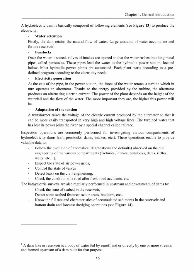
1.3.1.3 Working principle of a typical hydroelectric dam
Figure 13: Elements of typical hydroelectricity dam (TVA, 2005)
Chapter 1. General introduction
30
A hydroelectric dam is basically composed of following elements (see Figure 13) to produce the
electricity:
- Water retention
Firstly, the dam retains the natural flow of water. Large amounts of water accumulate and
form a reservoir1.
- Penstocks
Once the water is stored, valves of intakes are opened so that the water rushes into long metal
pipes called penstocks. These pipes lead the water to the hydraulic power station, located
below. Most hydraulic power plants are automated. Each plant starts according to a pre-
defined program according to the electricity needs.
- Electricity generation
At the exit of the pipe, in the power station, the force of the water rotates a turbine which in
turn operates an alternator. Thanks to the energy provided by the turbine, the alternator
produces an alternating electric current. The power of the plant depends on the height of the
waterfall and the flow of the water. The more important they are, the higher this power will
be.
- Adaptation of the tension
A transformer raises the voltage of the electric current produced by the alternator so that it
can be more easily transported in very high and high voltage lines. The turbined water that
has lost its power joins the river by a special channel called tailrace.
Inspection operations are commonly performed for investigating various compartments of
hydroelectricity dams (raft, penstocks, dams, intakes, etc.). These operations enable to provide
valuable data to:
- Follow the evolution of anomalies (degradations and defaults) observed on the civil
engineering of the various compartments (factories, intakes, penstocks, dams, riffles,
weirs, etc…),
- Inspect the state of air power grids,
- Control the state of valves
- Detect leaks on the civil engineering,
- Check the condition of a road after frost, road accidents, etc.
The bathymetric surveys are also regularly performed in upstream and downstream of dams to:
- Check the state of seabed in the reservoir,
- Detect some seabed features: scour areas, boulders, etc…
- Know the fill rate and characteristics of accumulated sediments in the reservoir and
bottom drain and forecast dredging operations (see Figure 14).
1 A dam lake or reservoir is a body of water fed by runoff and or directly by one or more streams
and formed upstream of a dam built for that purpose.
Chapter 1. General introduction
31
Figure 14 : Submergence study of dam at 50 m of water depth (Guillot, 2015)
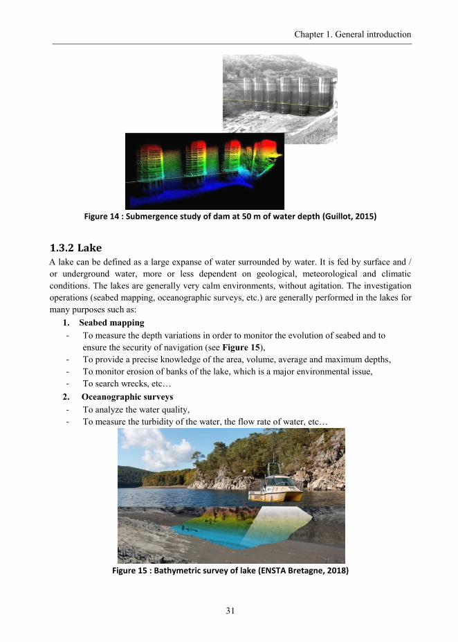
1.3.2 Lake A lake can be defined as a large expanse of water surrounded by water. It is fed by surface and /
or underground water, more or less dependent on geological, meteorological and climatic
conditions. The lakes are generally very calm environments, without agitation. The investigation
operations (seabed mapping, oceanographic surveys, etc.) are generally performed in the lakes for
many purposes such as:
1. Seabed mapping
- To measure the depth variations in order to monitor the evolution of seabed and to
ensure the security of navigation (see Figure 15),
- To provide a precise knowledge of the area, volume, average and maximum depths,
- To monitor erosion of banks of the lake, which is a major environmental issue,
- To search wrecks, etc…
2. Oceanographic surveys
- To analyze the water quality,
- To measure the turbidity of the water, the flow rate of water, etc…
Figure 15 : Bathymetric survey of lake (ENSTA Bretagne, 2018)
Chapter 1. General introduction
32
1.3.3 Rivers and channels The rivers and channels are navigational ways used daily by the vessels to transport goods and
people to docks of port (or a mooring area, shelter, etc.) or to perform survey operations. To
safely navigate, the vessels access to shelter (port, etc.) via a channel which has the greatest depth
of water under the keel. The channel is usually delineated by regularly spaced beacons and a line
of landmarks in order to confirm their correct positions in the event that beacons are degraded. In
a channel, the buoyage conventions are peculiar: the shape and the color of the beacons are
codified under the name of lateral marking system. Signs of important channels are lit by fires at
night. The rivers and channels have significant economic importance for countries with a well-
equipped waterway network such as the France, the England, etc. Thus, hydrographic surveys and
inspection campaigns are regularly performed in these areas to:
1. Bathymetric surveys of control
- Verify the presence and positions of beacons or markers,
- Measure the depth variations in order to monitor the evolution of seabed and to ensure
the security of navigation, etc.
- Check the quantity of dredged material volume during dredging operations,
2. Bathymetric surveys of reconnaissance
- Determine the waterways,
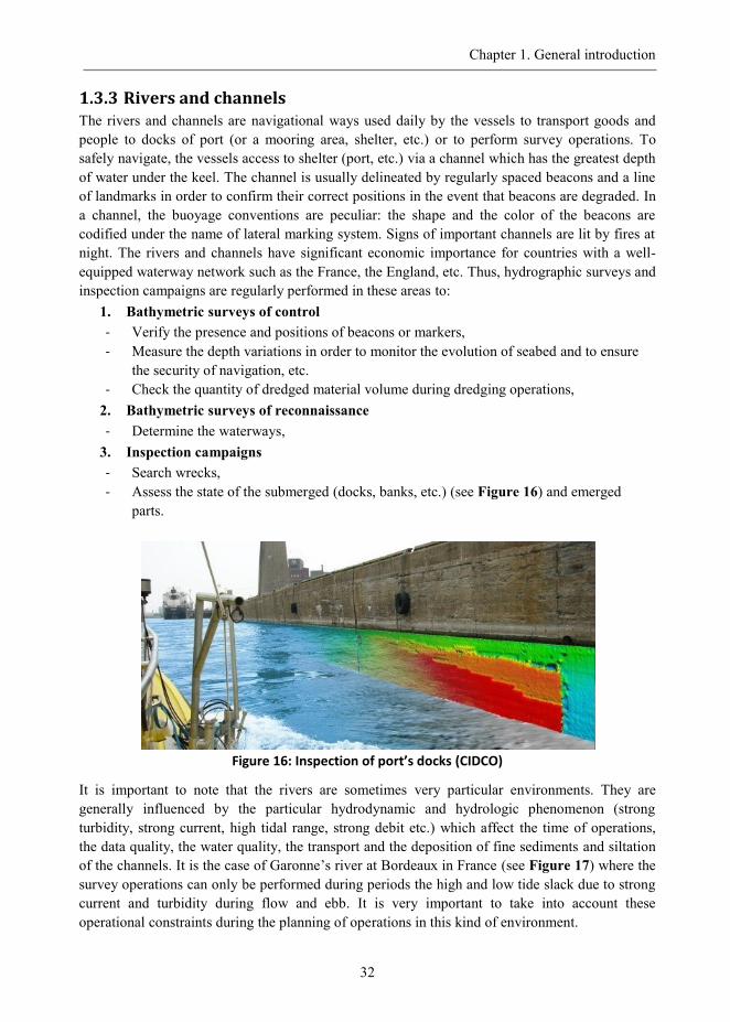
3. Inspection campaigns
- Search wrecks,
- Assess the state of the submerged (docks, banks, etc.) (see Figure 16) and emerged
parts.
Figure 16: Inspection of port’s docks (CIDCO)
It is important to note that the rivers are sometimes very particular environments. They are
generally influenced by the particular hydrodynamic and hydrologic phenomenon (strong
turbidity, strong current, high tidal range, strong debit etc.) which affect the time of operations,
the data quality, the water quality, the transport and the deposition of fine sediments and siltation
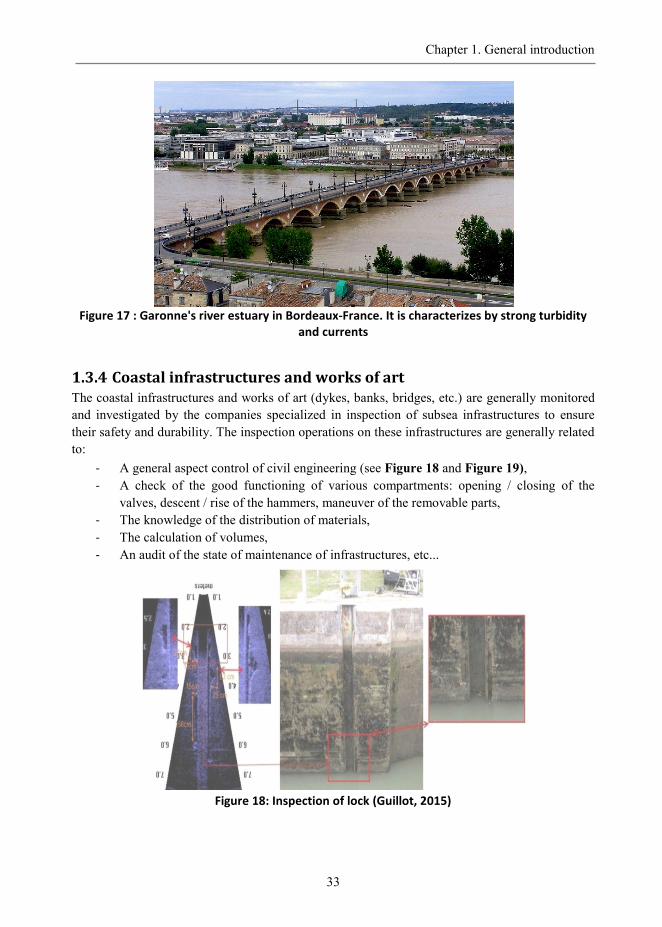
of the channels. It is the case of Garonne‟s river at Bordeaux in France (see Figure 17) where the
survey operations can only be performed during periods the high and low tide slack due to strong
current and turbidity during flow and ebb. It is very important to take into account these
operational constraints during the planning of operations in this kind of environment.
Chapter 1. General introduction
33
Figure 17 : Garonne's river estuary in Bordeaux-France. It is characterizes by strong turbidity
and currents
1.3.4 Coastal infrastructures and works of art The coastal infrastructures and works of art (dykes, banks, bridges, etc.) are generally monitored
and investigated by the companies specialized in inspection of subsea infrastructures to ensure
their safety and durability. The inspection operations on these infrastructures are generally related
to:
- A general aspect control of civil engineering (see Figure 18 and Figure 19),
- A check of the good functioning of various compartments: opening / closing of the
valves, descent / rise of the hammers, maneuver of the removable parts,
- The knowledge of the distribution of materials,
- The calculation of volumes,
- An audit of the state of maintenance of infrastructures, etc...
Figure 18: Inspection of lock (Guillot, 2015)
Chapter 1. General introduction
34
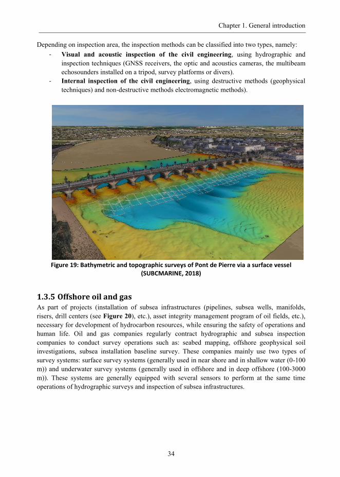
Depending on inspection area, the inspection methods can be classified into two types, namely:
- Visual and acoustic inspection of the civil engineering, using hydrographic and
inspection techniques (GNSS receivers, the optic and acoustics cameras, the multibeam
echosounders installed on a tripod, survey platforms or divers).
- Internal inspection of the civil engineering, using destructive methods (geophysical
techniques) and non-destructive methods electromagnetic methods).
Figure 19: Bathymetric and topographic surveys of Pont de Pierre via a surface vessel
(SUBCMARINE, 2018)
1.3.5 Offshore oil and gas As part of projects (installation of subsea infrastructures (pipelines, subsea wells, manifolds,
risers, drill centers (see Figure 20), etc.), asset integrity management program of oil fields, etc.),
necessary for development of hydrocarbon resources, while ensuring the safety of operations and
human life. Oil and gas companies regularly contract hydrographic and subsea inspection
companies to conduct survey operations such as: seabed mapping, offshore geophysical soil
investigations, subsea installation baseline survey. These companies mainly use two types of
survey systems: surface survey systems (generally used in near shore and in shallow water (0-100
m)) and underwater survey systems (generally used in offshore and in deep offshore (100-3000
m)). These systems are generally equipped with several sensors to perform at the same time
operations of hydrographic surveys and inspection of subsea infrastructures.
Chapter 1. General introduction
35
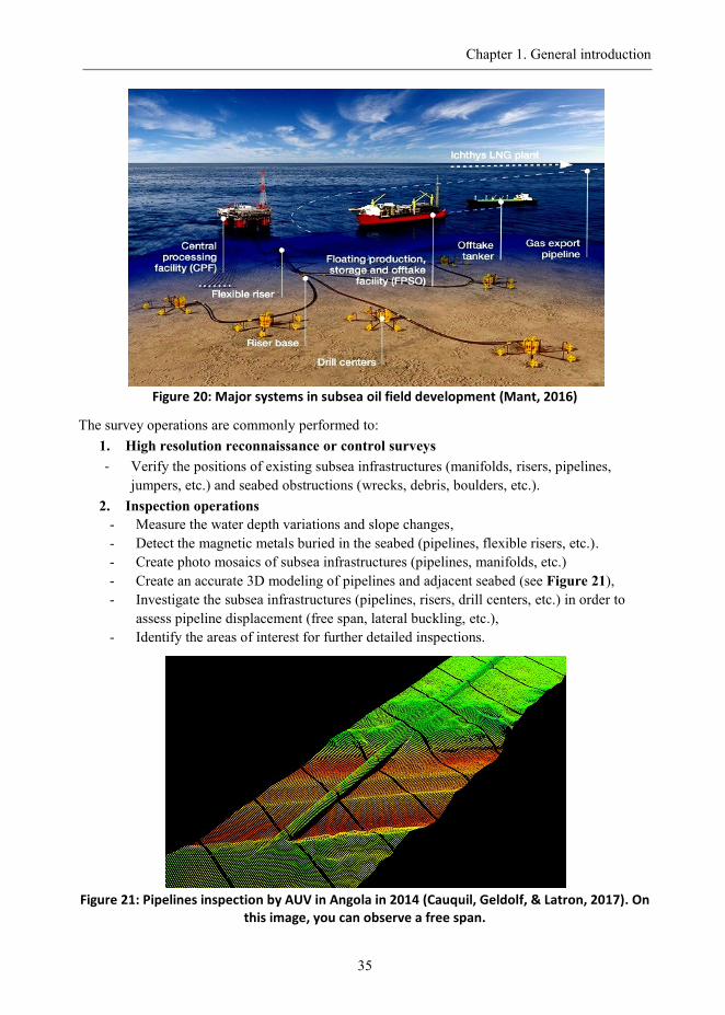
Figure 20: Major systems in subsea oil field development (Mant, 2016)
The survey operations are commonly performed to:
1. High resolution reconnaissance or control surveys
- Verify the positions of existing subsea infrastructures (manifolds, risers, pipelines,
jumpers, etc.) and seabed obstructions (wrecks, debris, boulders, etc.).
2. Inspection operations
- Measure the water depth variations and slope changes,
- Detect the magnetic metals buried in the seabed (pipelines, flexible risers, etc.).
- Create photo mosaics of subsea infrastructures (pipelines, manifolds, etc.)
- Create an accurate 3D modeling of pipelines and adjacent seabed (see Figure 21),
- Investigate the subsea infrastructures (pipelines, risers, drill centers, etc.) in order to
assess pipeline displacement (free span, lateral buckling, etc.),
- Identify the areas of interest for further detailed inspections.
Figure 21: Pipelines inspection by AUV in Angola in 2014 (Cauquil, Geldolf, & Latron, 2017). On
this image, you can observe a free span.
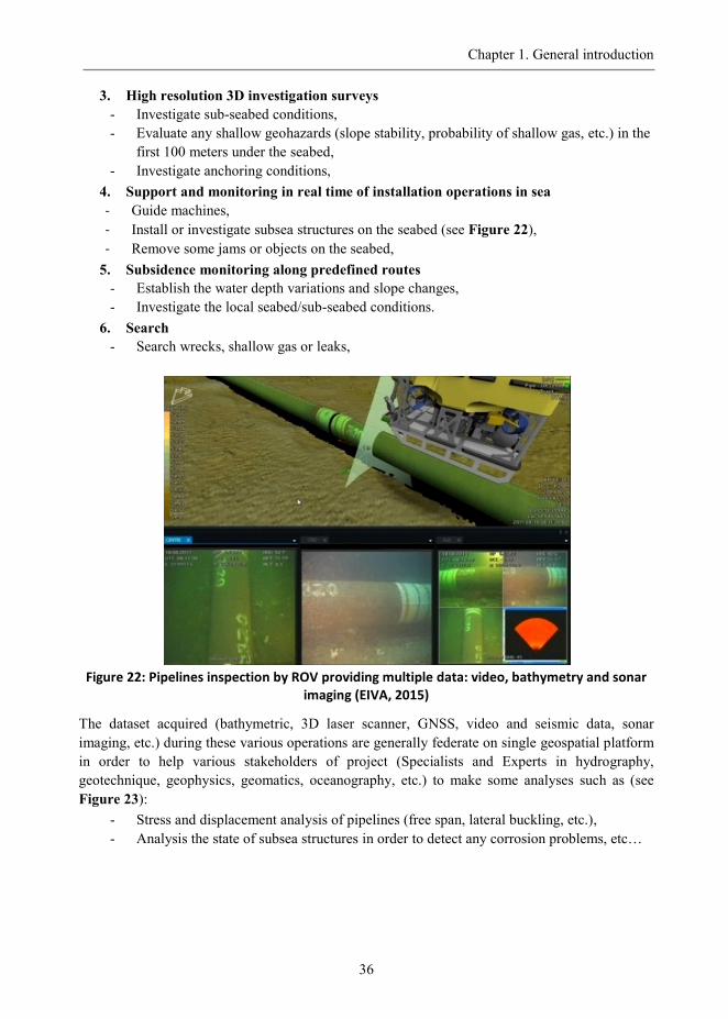
Chapter 1. General introduction
36
3. High resolution 3D investigation surveys
- Investigate sub-seabed conditions,
- Evaluate any shallow geohazards (slope stability, probability of shallow gas, etc.) in the
first 100 meters under the seabed,
- Investigate anchoring conditions,
4. Support and monitoring in real time of installation operations in sea
- Guide machines,
- Install or investigate subsea structures on the seabed (see Figure 22),
- Remove some jams or objects on the seabed,
5. Subsidence monitoring along predefined routes
- Establish the water depth variations and slope changes,
- Investigate the local seabed/sub-seabed conditions.
6. Search
- Search wrecks, shallow gas or leaks,
Figure 22: Pipelines inspection by ROV providing multiple data: video, bathymetry and sonar
imaging (EIVA, 2015)
The dataset acquired (bathymetric, 3D laser scanner, GNSS, video and seismic data, sonar
imaging, etc.) during these various operations are generally federate on single geospatial platform
in order to help various stakeholders of project (Specialists and Experts in hydrography,
geotechnique, geophysics, geomatics, oceanography, etc.) to make some analyses such as (see
Figure 23):
- Stress and displacement analysis of pipelines (free span, lateral buckling, etc.),
- Analysis the state of subsea structures in order to detect any corrosion problems, etc…
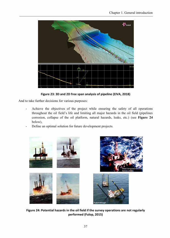
Chapter 1. General introduction
37
Figure 23: 3D and 2D free span analysis of pipeline (EIVA, 2018)
And to take further decisions for various purposes:
- Achieve the objectives of the project while ensuring the safety of all operations
throughout the oil field‟s life and limiting all major hazards in the oil field (pipelines
corrosion, collapse of the oil platform, natural hazards, leaks, etc.) (see Figure 24
below),
- Define an optimal solution for future development projects.
Figure 24: Potential hazards in the oil field if the survey operations are not regularly performed (Fulop, 2015)
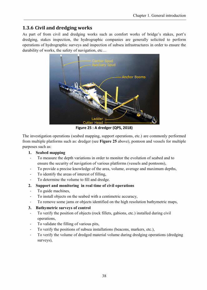
Chapter 1. General introduction
38
1.3.6 Civil and dredging works As part of from civil and dredging works such as comfort works of bridge‟s stakes, port‟s
dredging, stakes inspection, the hydrographic companies are generally solicited to perform
operations of hydrographic surveys and inspection of subsea infrastructures in order to ensure the
durability of works, the safety of navigation, etc…
Figure 25 : A dredger (QPS, 2018)
The investigation operations (seabed mapping, support operations, etc.) are commonly performed
from multiple platforms such as: dredger (see Figure 25 above), pontoon and vessels for multiple
purposes such as:
1. Seabed mapping
- To measure the depth variations in order to monitor the evolution of seabed and to
ensure the security of navigation of various platforms (vessels and pontoons),
- To provide a precise knowledge of the area, volume, average and maximum depths,
- To identify the areas of interest of filling,
- To determine the volume to fill and dredge.
2. Support and monitoring in real time of civil operations
- To guide machines,
- To install objects on the seabed with a centimetric accuracy,
- To remove some jams or objects identified on the high resolution bathymetric maps,
3. Bathymetric surveys of control
- To verify the position of objects (rock fillets, gabions, etc.) installed during civil
operations,
- To validate the filling of various pits,
- To verify the positions of subsea installations (beacons, markers, etc.),
- To verify the volume of dredged material volume during dredging operations (dredging
surveys),
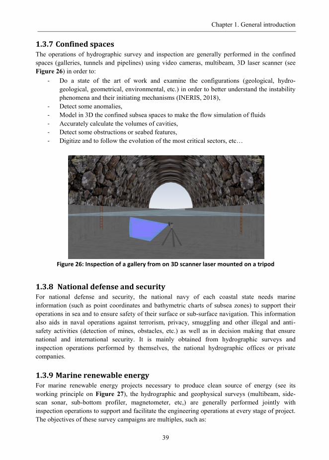
Chapter 1. General introduction
39
1.3.7 Confined spaces The operations of hydrographic survey and inspection are generally performed in the confined
spaces (galleries, tunnels and pipelines) using video cameras, multibeam, 3D laser scanner (see
Figure 26) in order to:
- Do a state of the art of work and examine the configurations (geological, hydro-
geological, geometrical, environmental, etc.) in order to better understand the instability
phenomena and their initiating mechanisms (INERIS, 2018),
- Detect some anomalies,
- Model in 3D the confined subsea spaces to make the flow simulation of fluids
- Accurately calculate the volumes of cavities,
- Detect some obstructions or seabed features,
- Digitize and to follow the evolution of the most critical sectors, etc…
Figure 26: Inspection of a gallery from on 3D scanner laser mounted on a tripod
1.3.8 National defense and security For national defense and security, the national navy of each coastal state needs marine
information (such as point coordinates and bathymetric charts of subsea zones) to support their
operations in sea and to ensure safety of their surface or sub-surface navigation. This information
also aids in naval operations against terrorism, privacy, smuggling and other illegal and anti-
safety activities (detection of mines, obstacles, etc.) as well as in decision making that ensure
national and international security. It is mainly obtained from hydrographic surveys and
inspection operations performed by themselves, the national hydrographic offices or private
companies.
1.3.9 Marine renewable energy For marine renewable energy projects necessary to produce clean source of energy (see its
working principle on Figure 27), the hydrographic and geophysical surveys (multibeam, side-
scan sonar, sub-bottom profiler, magnetometer, etc,) are generally performed jointly with
inspection operations to support and facilitate the engineering operations at every stage of project.
The objectives of these survey campaigns are multiples, such as:
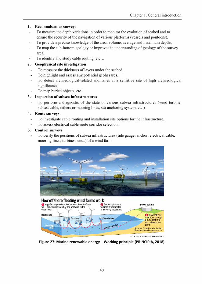
Chapter 1. General introduction
40
1. Reconnaissance surveys
- To measure the depth variations in order to monitor the evolution of seabed and to
ensure the security of the navigation of various platforms (vessels and pontoons),
- To provide a precise knowledge of the area, volume, average and maximum depths,
- To map the sub-bottom geology or improve the understanding of geology of the survey
area,
- To identify and study cable routing, etc…
2. Geophysical site investigation
- To measure the thickness of layers under the seabed,
- To highlight and assess any potential geohazards,
- To detect archaeological-related anomalies at a sensitive site of high archaeological
significance.
- To map buried objects, etc..
3. Inspection of subsea infrastructures
- To perform a diagnostic of the state of various subsea infrastructures (wind turbine,
subsea cable, tethers or mooring lines, sea anchoring system, etc.)
4. Route surveys
- To investigate cable routing and installation site options for the infrastructure,
- To assess electrical cable route corridor selection,
5. Control surveys
- To verify the positions of subsea infrastructures (tide gauge, anchor, electrical cable,
mooring lines, turbines, etc...) of a wind farm.
Figure 27: Marine renewable energy – Working principle (PRINCIPIA, 2018)