Embed Size (px)
Citation preview

BATTERY CHARGERBATTERY CHARGERRLDRLD
USER'S MANUALUSER'S MANUAL

(THIS PAGE WAS INTENTIONALLY LEFT BLANK)
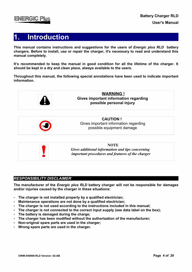
TABLE OF CONTENTS· 1. Introduction................................................................................................. 4
· RESPONSIBILITY DISCLAIMER................................................................................. 4
· 2. Safety instructions and warnings............................................................. 5· GENERAL.................................................................................................................... 5· SHOCK PREVENTION................................................................................................ 5· BURN AND BODILY INJURY PREVENTION.............................................................. 6· FIRE AND EXPLOSION PREVENTION...................................................................... 6· MEDICAL AND FIRST AID TREATMENT................................................................... 6· EQUIPMENT WARNING LABELS............................................................................... 6
· 3. Description.................................................................................................. 7· 4. Installation................................................................................................... 9
· INTERNAL VIEW OF THE CHARGER, CABINET A................................................. 11· INTERNAL VIEW OF THE CHARGER, CABINET B................................................. 12· AC VOLTAGE SELECTION 3 x 220/380 V - CABINET A......................................... 13· AC VOLTAGE SELECTION 3 x 220/380 V - CABINET B......................................... 14· AC INPUT VOLTAGE ADJUSTMENT - CABINET A................................................. 15· AC INPUT VOLTAGE ADJUSTMENT - CABINET B................................................. 16· GROUNDING AND LINE CONNECTION.................................................................. 17
· 5. Operation................................................................................................... 18· PRELIMINARY CONTROLS...................................................................................... 18· BATTERY CONNECTION, VOLTAGE CHECK AND AUTOSTART......................... 19· CHARGE OPERATION.............................................................................................. 19· AUTOMATIC DATA SAVING..................................................................................... 22· AUTOMATIC AND MANUAL CHARGE TERMINATION........................................... 22· EQUALIZATION......................................................................................................... 23· MAINTENANCE......................................................................................................... 24
· 6. Trouble Shooting...................................................................................... 25· 7. Cabinet Tables.......................................................................................... 27· 8. Spare parts list.......................................................................................... 28
Battery Charger RLDUser's Manual
1. IntroductionThis manual contains instructions and suggestions for the users of Energic plus RLD battery chargers. Before to install, use or repair the charger, it's necessary to read and understand this manual completely.
It’s recommended to keep the manual in good condition for all the lifetime of the charger. It should be kept in a dry and clean place, always available to the users.
Throughout this manual, the following special annotations have been used to indicate important information.
RESPONSIBILITY DISCLAIMERThe manufacturer of the Energic plus RLD battery charger will not be responsible for damages and/or injuries caused by the charger in these situations:
• The charger is not installed properly by a qualified electrician;• Maintenance operations are not done by a qualified electrician;• The charger is not used according to the instructions included in this manual;• The charger is not connected to the correct input supply (see data label on the box);• The battery is damaged during the charge;• The charger has been modified without the authorization of the manufacturer;• Non-original spare parts are used in the charger;• Wrong spare parts are used in the charger.
OWM-040906-RLD Version: 02-AB Page 4 of 29
WARNING !Gives important information regarding
possible personal injury
CAUTION !Gives important information regarding
possible equipment damage
NOTEGives additional information and tips concerning important procedures and features of the charger
Battery Charger RLDUser's Manual
2. Safety instructions and warningsGENERALBattery chargers can cause injury or death, or damage to other equipment or property, if the user does not strictly observe all safety rules and take precautionary actions.Safe practices must be learned through study and training before using this equipment.Only qualified personnel should install, use, or service this battery charger.
SHOCK PREVENTION
Bare conductors, or terminals in the output circuit, or ungrounded, electrically-live equipments can fatally shock a person. To protect against shock, have competent electrician verify that the equipment is adequately grounded and learn what terminals and parts are electrically HOT.The body’s electrical resistance is decreased when wet, permitting dangerous current to flow through the body. Do not work in damp area without being extremely careful. Stand on dry rubber mat or dry wood and use insulating gloves when dampness or sweat cannot be avoided. Keep clothing dry.
INSTALLATION AND GROUNDING – Electrica equipment must be installed and mantained in accordance with all the applicable national and local codes.A power disconnect switch must be located at the equipment. Check the data label for voltage and phase requirements. If only 3-phase power is available, connect single-phase equipment to ONLY TWO WIRES of the 3-phase line.DO NOT CONNECT the equipment grounding conductor to the third live wire of the 3-phase line as this makes the equipment frame electrically HOT, which can cause a fatal shock.If a grounding conductor is part of the power supply cable, be sure to connect it to a properly grounded switch box or building ground. If not part of the supply cable, use a separate grounding conductor. Don’t remove a ground prong from any plug. Use correct mating receptacles. Check ground for electrical continuity before using equipment. The grounding conductor must be of a size equal to or larger than the size recommended by Code or this manual.
CHARGING LEADS – Inspect leads often for damage to the insulation. Replace or repair cracked or worn leads immediately. Use leads having sufficient capacity to carry the operating current without overheating.Never extend the charging leads without prior approval of the manufacturer. Extending the charging leads without prior approval of the manufacturer may cause wrong operation of the charger and voids the warranty.
BATTERY TERMINALS – Do not touch battery terminals while equipment is operating.
SERVICE AND MAINTENANCE – Shut OFF all power at the disconnect switch or line breaker BEFORE inspecting, adjusting, or servicing the equipment. Lock switch OPEN (or remove line fuses) so that the power cannot be turned ON accidentally.Disconnect power to equipment if it is to be left unattended or out of service.Disconnect battery from charger.Measure voltage on capacitors and, if there is any voltage reading, wait 5 minutes before to proceed.Keep inside parts clean and dry. Dirt and/or moisture can cause insulation failure. This failure can result in high voltage at the charger output.
OWM-040906-RLD Version: 02-AB Page 5 of 29
Battery Charger RLDUser's Manual
BURN AND BODILY INJURY PREVENTIONThe battery produces very high currents when short circuited, and will burn the skin severely if in contact with any metal conductor that is carrying this current.Do not permit rings on fingers to come in contact with battery terminals or the cell connectors on top of the battery.Battery acid is very corrosive. Alwais wear correct eye and body protection when near batteries.
FIRE AND EXPLOSION PREVENTIONWhen batteries are being recharged, they generate hydrogen gas that is explosive in certain concentrations in air (the flammability or explosive limits are 4.1% to 72% hydrogen in air). The spark-retarding vents help slow the rate of release of hydrogen, but the escaping hydrogen may form an explosive atmosphere around the battery if ventilation is poor.The ventilation system should be designed to provide an adequate amount of fresh air for the number of batteries being charged. This is essential to prevent an explosion. Always keep sparks, flames, burning cigarettes, and other sources of ignition away from the battery recharging area. Do not break "live" circuits at the terminals of batteries. Do not lay tools or anything that is metallic on top of any battery.
To prevent arcing and burning of the connector contacts, be sure the charger is OFF before connecting or disconnecting the battery. The digital display must be completely OFF.
MEDICAL AND FIRST AID TREATMENTFirst aid facilities and a qualified first aid person should be available for each shift for immediate treatment of electrical shock victims.
EMERGENCY FIRST AID: Call phisician and ambulance immediately and use First Aid techniques recommended by the American Red Cross.In case of acid in the eyes, flush very well with clean water and obtain professional medical attention immediately.
EQUIPMENT WARNING LABELSInspect all precautionary labels on the equipment.Order and replace all labels that cannot be easily read.
OWM-040906-RLD Version: 02-AB Page 6 of 29
DANGER: ELECTRICAL SHOCK CAN BE FATAL.
If person is unconscious and electric shock is suspected, do not touch person if he or she is in contact with charging equipment, battery, charging leads, or other live electrical parts. Disconnect power at wall switch and then use First Aid.Dry wood, wooden broom, and other insulating material can be used to move cables, if necessary, away from person.IF BREATHING IS DIFFICULT, give oxygen.IF NOT BREATHING, BEGIN ARTIFICIAL BREATHING, such as mouth-to-mouth.IF PULSE IS ABSENT, BEGIN ARTIFICIAL CIRCULATION, such as external heart massage.
Battery Charger RLDUser's Manual
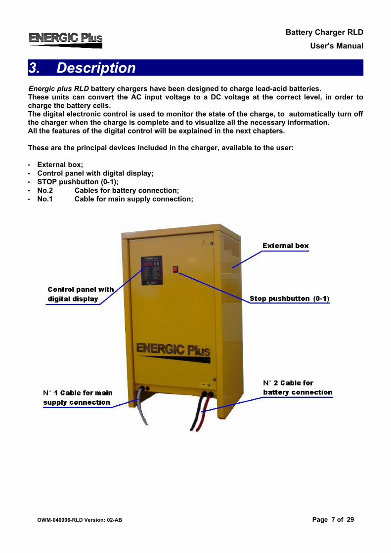
3. DescriptionEnergic plus RLD battery chargers have been designed to charge lead-acid batteries. These units can convert the AC input voltage to a DC voltage at the correct level, in order to charge the battery cells.The digital electronic control is used to monitor the state of the charge, to automatically turn off the charger when the charge is complete and to visualize all the necessary information.All the features of the digital control will be explained in the next chapters.
These are the principal devices included in the charger, available to the user:
• External box;• Control panel with digital display;• STOP pushbutton (0-1);• No.2 Cables for battery connection;• No.1 Cable for main supply connection;
OWM-040906-RLD Version: 02-AB Page 7 of 29
Battery Charger RLDUser's Manual
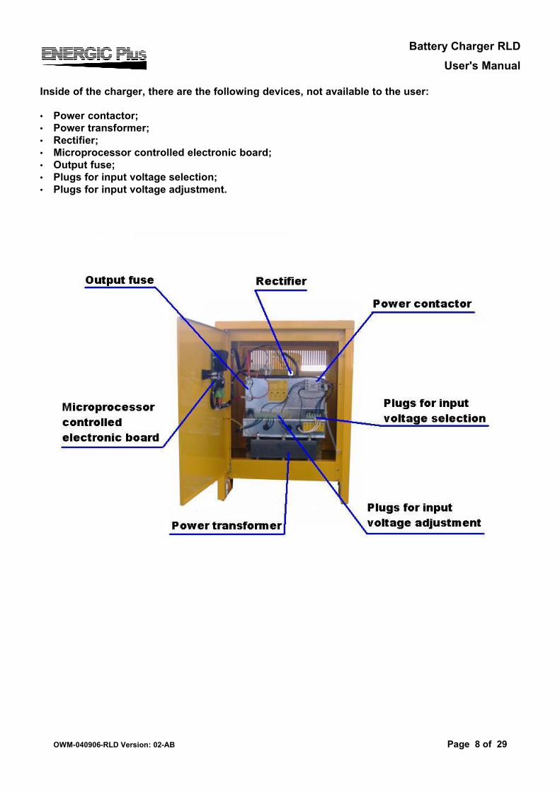
Inside of the charger, there are the following devices, not available to the user:
• Power contactor;• Power transformer;• Rectifier;• Microprocessor controlled electronic board;• Output fuse;• Plugs for input voltage selection;• Plugs for input voltage adjustment.
OWM-040906-RLD Version: 02-AB Page 8 of 29
Battery Charger RLDUser's Manual
4. Installation
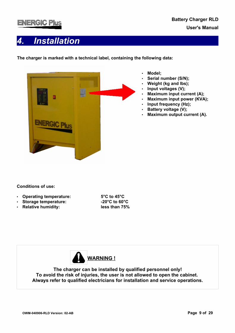
The charger is marked with a technical label, containing the following data:
• Model;• Serial number (S/N);• Weight (kg and lbs);• Input voltages (V);• Maximum input current (A);• Maximum input power (KVA);• Input frequency (Hz);• Battery voltage (V);• Maximum output current (A).
Conditions of use:
• Operating temperature: 5°C to 45°C• Storage temperature: -20°C to 60°C• Relative humidity: less than 75%
OWM-040906-RLD Version: 02-AB Page 9 of 29
WARNING !
The charger can be installed by qualified personnel only!To avoid the risk of injuries, the user is not allowed to open the cabinet.
Always refer to qualified electricians for installation and service operations.
Battery Charger RLDUser's Manual
OWM-040906-RLD Version: 02-AB Page 10 of 29
WARNING !
To prevent fire or shock hazard, do not expose the charger to rain or moisture. Do not use the e charger in presence of flammable gas, because it can generate sparks!
Do not install the charger near flammable materials.
WARNING !
To reduce the risk of fire, the charger must be installed on a floor of non-combustible material.
If this is not possible, a floor plate of at least 1,6mm steel extended at least 150mm beyond the charger on all sides must be installed.
CAUTION !
Allow adequate air circulation to prevent internal heat buildup.Do not place the unit near materials that may block the ventilation slots.
Do not install the unit near heat sources such as radiators or air ducts, or in a place subject to direct sunlight, excessive dust, mechanical vibration or shock.
CAUTION !
The operations and settings described in this chapter are fundamental for the good functionality of the charger.
Improper settings can cause severe damage to the charger and the battery!
Before to install the charger:Check that the charger input voltage (V) is identical to your AC power supply voltage.
Check that the charger max input power (KVA) is available from your AC power supply.
Battery Charger RLDUser's Manual
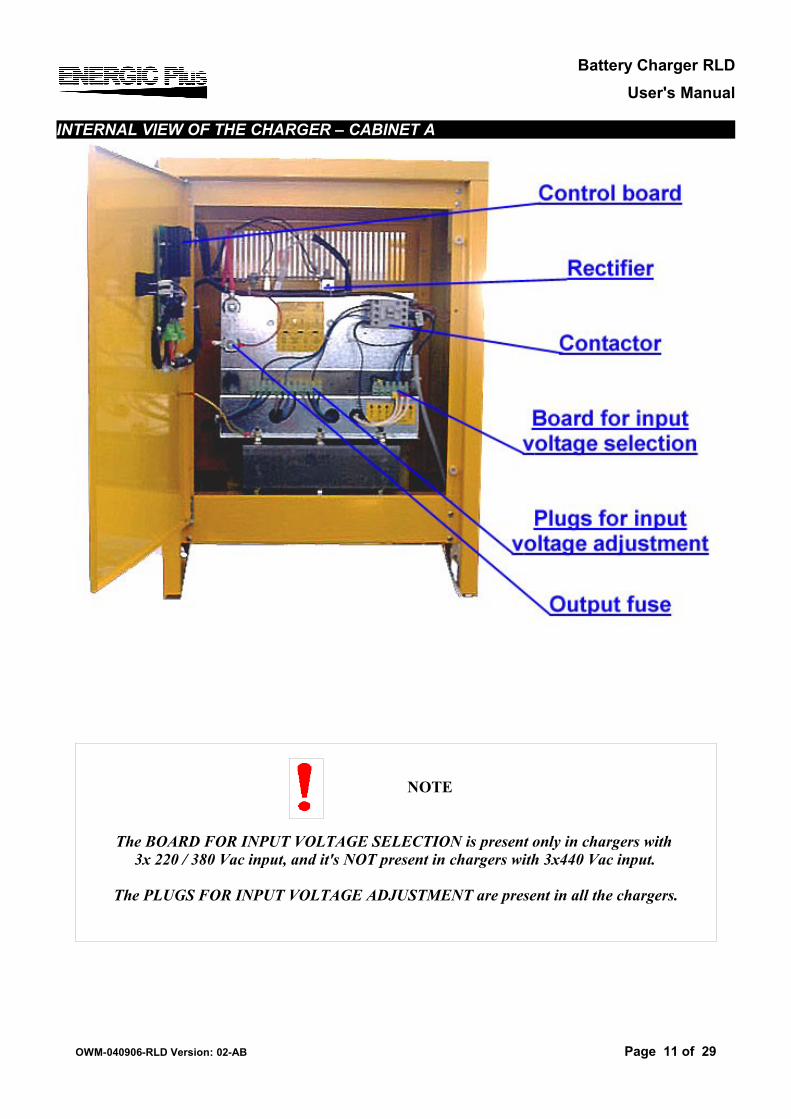
INTERNAL VIEW OF THE CHARGER – CABINET A
OWM-040906-RLD Version: 02-AB Page 11 of 29
NOTE
The BOARD FOR INPUT VOLTAGE SELECTION is present only in chargers with 3x 220 / 380 Vac input, and it's NOT present in chargers with 3x440 Vac input.
The PLUGS FOR INPUT VOLTAGE ADJUSTMENT are present in all the chargers.
Battery Charger RLDUser's Manual
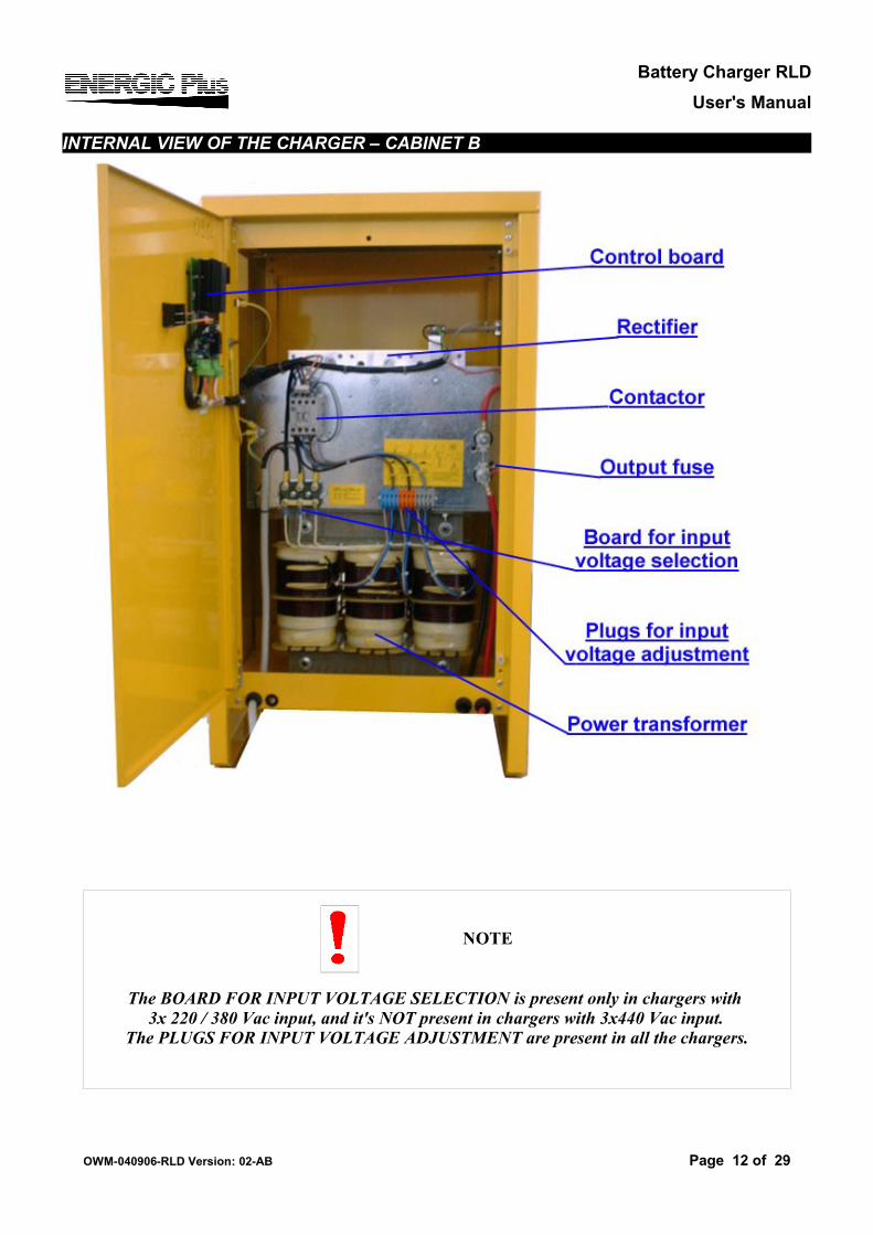
INTERNAL VIEW OF THE CHARGER – CABINET B
OWM-040906-RLD Version: 02-AB Page 12 of 29
NOTE
The BOARD FOR INPUT VOLTAGE SELECTION is present only in chargers with 3x 220 / 380 Vac input, and it's NOT present in chargers with 3x440 Vac input.
The PLUGS FOR INPUT VOLTAGE ADJUSTMENT are present in all the chargers.
Battery Charger RLDUser's Manual
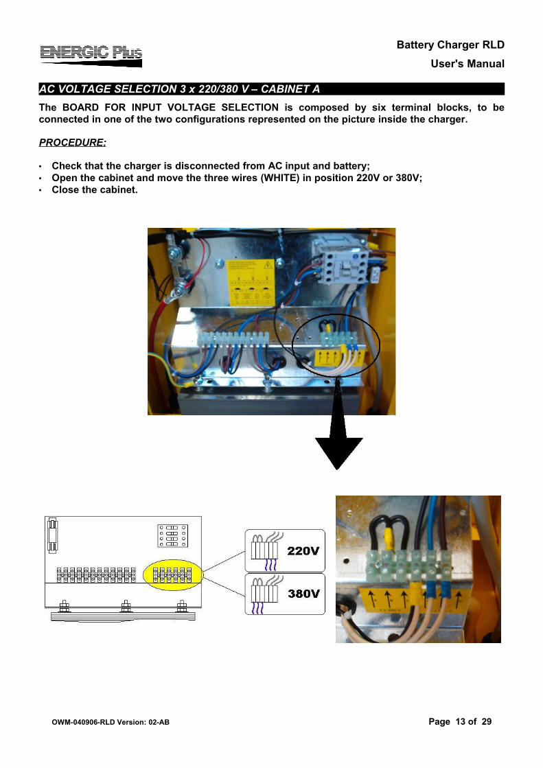
AC VOLTAGE SELECTION 3 x 220/380 V – CABINET AThe BOARD FOR INPUT VOLTAGE SELECTION is composed by six terminal blocks, to be connected in one of the two configurations represented on the picture inside the charger.
PROCEDURE:
• Check that the charger is disconnected from AC input and battery;• Open the cabinet and move the three wires (WHITE) in position 220V or 380V;• Close the cabinet.
OWM-040906-RLD Version: 02-AB Page 13 of 29
Battery Charger RLDUser's Manual
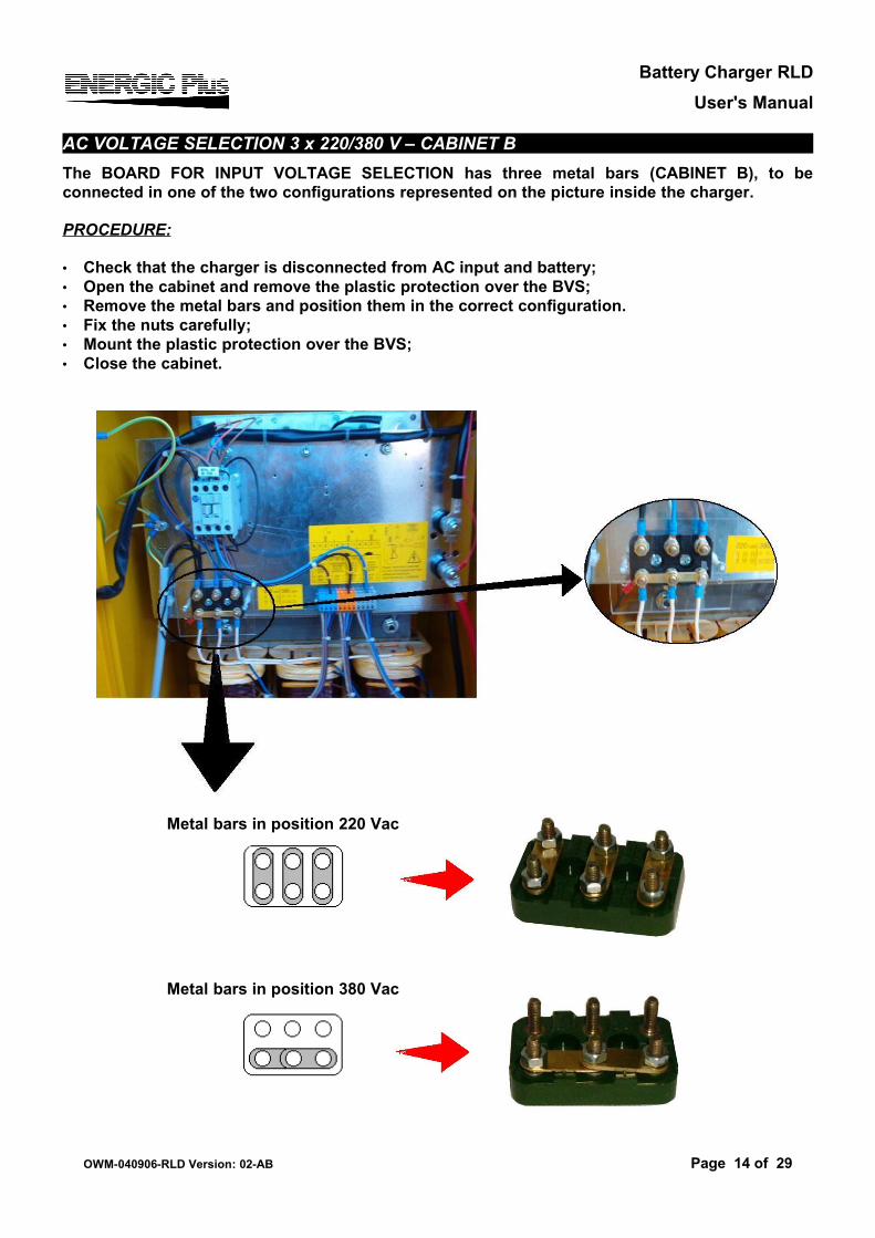
AC VOLTAGE SELECTION 3 x 220/380 V – CABINET BThe BOARD FOR INPUT VOLTAGE SELECTION has three metal bars (CABINET B), to be connected in one of the two configurations represented on the picture inside the charger.
PROCEDURE:
• Check that the charger is disconnected from AC input and battery;• Open the cabinet and remove the plastic protection over the BVS;• Remove the metal bars and position them in the correct configuration.• Fix the nuts carefully;• Mount the plastic protection over the BVS;• Close the cabinet.
Metal bars in position 220 Vac
Metal bars in position 380 Vac
OWM-040906-RLD Version: 02-AB Page 14 of 29
Battery Charger RLDUser's Manual
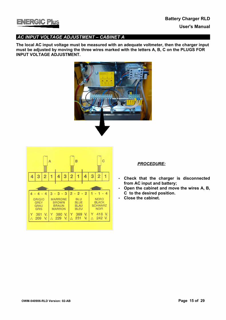
AC INPUT VOLTAGE ADJUSTMENT – CABINET AThe local AC input voltage must be measured with an adequate voltmeter, then the charger input must be adjusted by moving the three wires marked with the letters A, B, C on the PLUGS FOR INPUT VOLTAGE ADJUSTMENT.
PROCEDURE:
• Check that the charger is disconnected from AC input and battery;
• Open the cabinet and move the wires A, B, C to the desired position.
• Close the cabinet.
OWM-040906-RLD Version: 02-AB Page 15 of 29
Battery Charger RLDUser's Manual
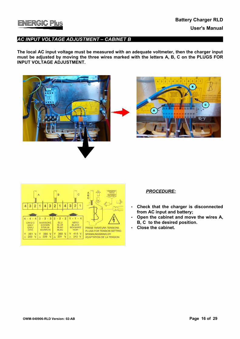
AC INPUT VOLTAGE ADJUSTMENT – CABINET B
The local AC input voltage must be measured with an adequate voltmeter, then the charger input must be adjusted by moving the three wires marked with the letters A, B, C on the PLUGS FOR INPUT VOLTAGE ADJUSTMENT.
PROCEDURE:
• Check that the charger is disconnected from AC input and battery;
• Open the cabinet and move the wires A, B, C to the desired position.
• Close the cabinet.
OWM-040906-RLD Version: 02-AB Page 16 of 29
Battery Charger RLDUser's Manual
GROUNDING AND LINE CONNECTION
If the charger is to be connected to the AC power supply with a flexible jacketed cable, one having a separate grounding conductor should be used. If, for any reason, an input cable which does not include a grounding conductor is used, the equipment must be grounded with separate conductor. Minimum size and color coding requirements must be in accordance with any applicable national or local code.
PROCEDURE
• Read on the data label the AC current value corresponding to the line voltage to which charger is to be connected. Using that current value, select the proper fuses, disconnect switch and power cable sizes, according with any applicable national or local code.
• Check that the charger is disconnected from AC input and battery;• Open the cabinet;• Mount the input cable and connect the four power conductors (three phase + ground) to the
terminal blocks; • Close the cabinet;• With disconnect switch on AC input power line on position “OFF” or “OPEN”, connect the
power cable coming from the charger to the switch and, then, install the fuses in the switch.
OWM-040906-RLD Version: 02-AB Page 17 of 29
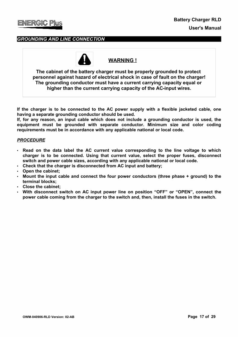
WARNING !
The cabinet of the battery charger must be properly grounded to protect personnel against hazard of electrical shock in case of fault on the charger!The grounding conductor must have a current carrying capacity equal or
higher than the current carrying capacity of the AC-input wires.
Battery Charger RLDUser's Manual
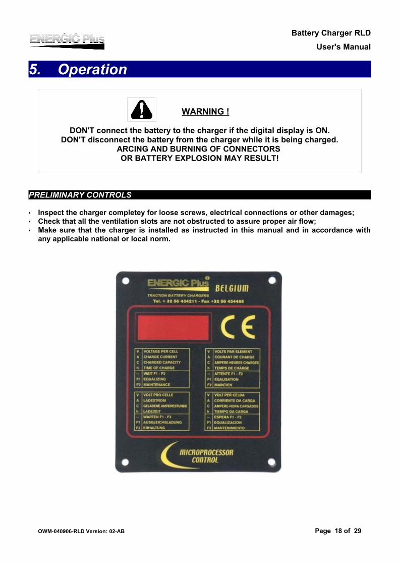
5. Operation
PRELIMINARY CONTROLS
• Inspect the charger completey for loose screws, electrical connections or other damages;• Check that all the ventilation slots are not obstructed to assure proper air flow;• Make sure that the charger is installed as instructed in this manual and in accordance with
any applicable national or local norm.
OWM-040906-RLD Version: 02-AB Page 18 of 29
WARNING !
DON'T connect the battery to the charger if the digital display is ON.DON'T disconnect the battery from the charger while it is being charged.
ARCING AND BURNING OF CONNECTORS OR BATTERY EXPLOSION MAY RESULT!
Battery Charger RLDUser's Manual
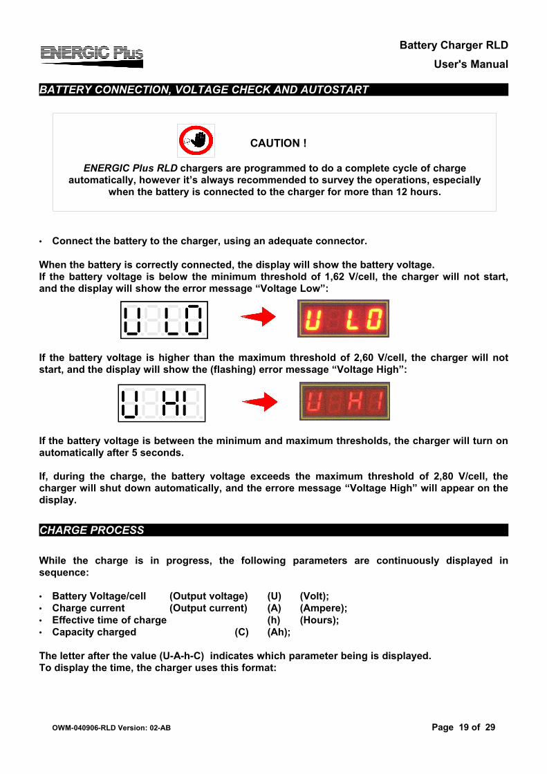
BATTERY CONNECTION, VOLTAGE CHECK AND AUTOSTART
• Connect the battery to the charger, using an adequate connector.
When the battery is correctly connected, the display will show the battery voltage. If the battery voltage is below the minimum threshold of 1,62 V/cell, the charger will not start, and the display will show the error message “Voltage Low”:
If the battery voltage is higher than the maximum threshold of 2,60 V/cell, the charger will not start, and the display will show the (flashing) error message “Voltage High”:
If the battery voltage is between the minimum and maximum thresholds, the charger will turn on automatically after 5 seconds.
If, during the charge, the battery voltage exceeds the maximum threshold of 2,80 V/cell, the charger will shut down automatically, and the errore message “Voltage High” will appear on the display.
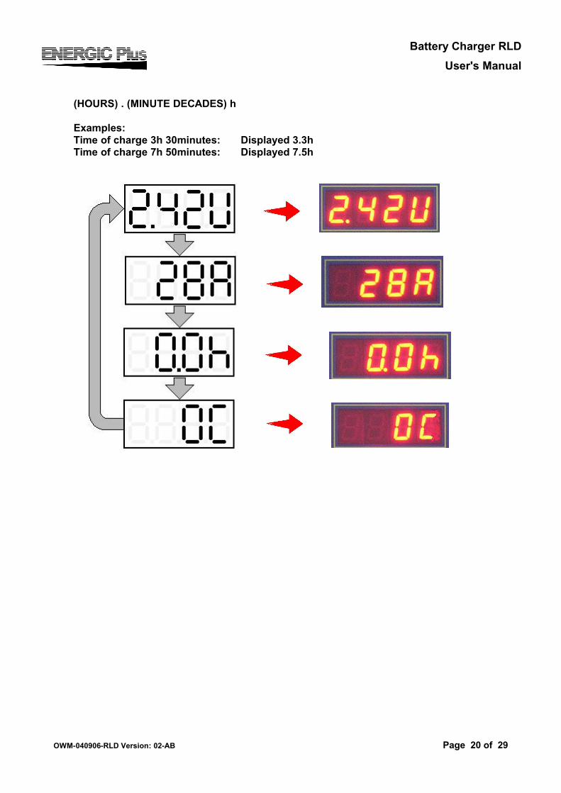
CHARGE PROCESS
While the charge is in progress, the following parameters are continuously displayed in sequence:
• Battery Voltage/cell (Output voltage) (U) (Volt);• Charge current (Output current) (A) (Ampere);• Effective time of charge (h) (Hours);• Capacity charged (C) (Ah);
The letter after the value (U-A-h-C) indicates which parameter being is displayed.To display the time, the charger uses this format:
OWM-040906-RLD Version: 02-AB Page 19 of 29
CAUTION !
ENERGIC Plus RLD chargers are programmed to do a complete cycle of charge automatically, however it’s always recommended to survey the operations, especially
when the battery is connected to the charger for more than 12 hours.
Battery Charger RLDUser's Manual
(HOURS) . (MINUTE DECADES) h
Examples:Time of charge 3h 30minutes: Displayed 3.3hTime of charge 7h 50minutes: Displayed 7.5h
OWM-040906-RLD Version: 02-AB Page 20 of 29
Battery Charger RLDUser's Manual
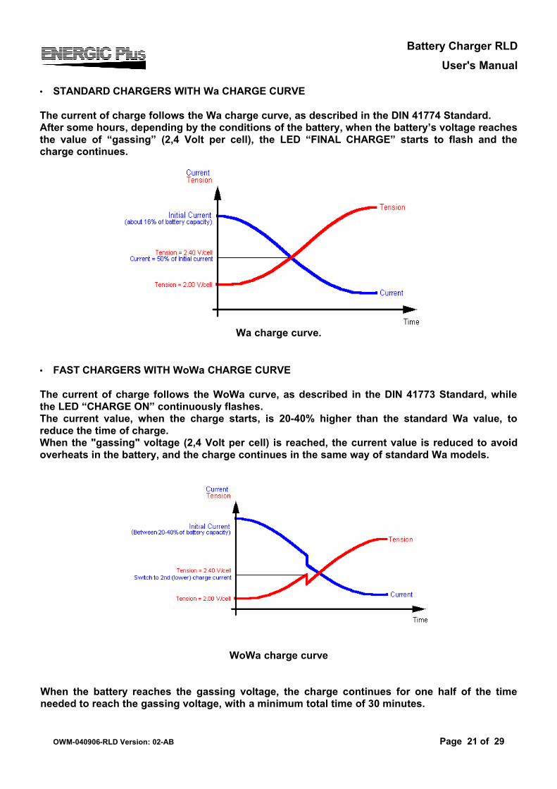
• STANDARD CHARGERS WITH Wa CHARGE CURVE
The current of charge follows the Wa charge curve, as described in the DIN 41774 Standard.After some hours, depending by the conditions of the battery, when the battery’s voltage reaches the value of “gassing” (2,4 Volt per cell), the LED “FINAL CHARGE” starts to flash and the charge continues.
Wa charge curve.
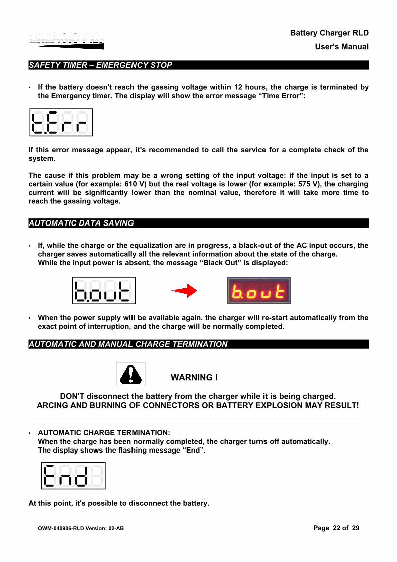
• FAST CHARGERS WITH WoWa CHARGE CURVE
The current of charge follows the WoWa curve, as described in the DIN 41773 Standard, while the LED “CHARGE ON” continuously flashes.The current value, when the charge starts, is 20-40% higher than the standard Wa value, to reduce the time of charge.When the "gassing" voltage (2,4 Volt per cell) is reached, the current value is reduced to avoid overheats in the battery, and the charge continues in the same way of standard Wa models.
WoWa charge curve
When the battery reaches the gassing voltage, the charge continues for one half of the time needed to reach the gassing voltage, with a minimum total time of 30 minutes.
OWM-040906-RLD Version: 02-AB Page 21 of 29
Battery Charger RLDUser's Manual
SAFETY TIMER – EMERGENCY STOP
• If the battery doesn't reach the gassing voltage within 12 hours, the charge is terminated by the Emergency timer. The display will show the error message “Time Error”:
If this error message appear, it's recommended to call the service for a complete check of the system.
The cause if this problem may be a wrong setting of the input voltage: if the input is set to a certain value (for example: 610 V) but the real voltage is lower (for example: 575 V), the charging current will be significantly lower than the nominal value, therefore it will take more time to reach the gassing voltage.
AUTOMATIC DATA SAVING
• If, while the charge or the equalization are in progress, a black-out of the AC input occurs, the charger saves automatically all the relevant information about the state of the charge.While the input power is absent, the message “Black Out” is displayed:
• When the power supply will be available again, the charger will re-start automatically from the exact point of interruption, and the charge will be normally completed.
AUTOMATIC AND MANUAL CHARGE TERMINATION
• AUTOMATIC CHARGE TERMINATION: When the charge has been normally completed, the charger turns off automatically.The display shows the flashing message “End”.
At this point, it's possible to disconnect the battery.
OWM-040906-RLD Version: 02-AB Page 22 of 29
WARNING !
DON'T disconnect the battery from the charger while it is being charged.ARCING AND BURNING OF CONNECTORS OR BATTERY EXPLOSION MAY RESULT!
Battery Charger RLDUser's Manual
• MANUAL CHARGE TERMINATION:The charge can be manually terminated in any moment, by pressing the red STOP pushbutton. The display will show the message “Stop”:
At this point, it's possible to disconnect the battery.
EQUALIZATION
The EQUALIZATION function is useful to keep all the cells of the battery at the same voltage level, even after years of continuous work. When a battery is charged/discharged everyday, it's suggested to equalize it weekly.
The charger, after a normally completed charge cycle, will add 4 extra charges of 30 minutes, with 15 hours interval between each charge.
During the interval between each equalization charge, the display will show the scrolling message: “End”:
When the equalization chargers are in progress, the display will show the message“F1”, followed by the current value:
OWM-040906-RLD Version: 02-AB Page 23 of 29
NOTES
After the charge termination, while the battery remains connected, the final values of [Voltage/cell], [Time] and [Capacity charged] remain stored in memory.
If the red STOP pushbutton is pressed, the display will show these values in sequence.
If the charge has been terminated manually, equalization and maintenance functions are automatically disabled.
Battery Charger RLDUser's Manual
MAINTENANCE
The MAINTENANCE function is useful to keep the battery in perfect condition when it's not used for an indefined time (weeks, months, ...).
It is sufficient to leave the battery connected to the charger: the control board will keep the battery voltage under control and will activate the charger automatically when the voltage falls below a predefined minimum theshold.
While the charger is off and the battery voltage is being monitored, this message is displayed:
If the voltage falls below the minimum threshold, the charger will give a refresh charge to pull up the voltage to a programmed maximum threshold, and the display will show the message: “F2”.
OWM-040906-RLD Version: 02-AB Page 24 of 29
NOTES
With this “voltage controlled” maintenance/refresh system, the battery will be kept in perfect condition for an undefined time, without any risk of undercharge or overcharge.
If the battery is in ideal condition (no self-discharge) the refresh charge will never be activated.If the battery is in bad condition (self-discharge is significant), the refresh charge will be often
activated and the battery will be kept charged without problems.
Battery Charger RLDUser's Manual
6. Trouble shooting
SYMPTOM POSSIBLE CAUSES ACTION
Charger does not react to battery
being connected, and display
remains OFF.
A
1 Battery not connected properly. Check battery connectors/harness.
2 Charger has been connected to forklift motor connector.
Disconnect forkift motor andconnect battery.
3 Output cables reversed. Check charger, connectors and battery polarities. Output fuse is probably blown.
4 Bad control board connection. Check board connectors (green).5 Bad control board. Replace control board.
The charger-process aborts itself and the
message
appear.
B Output fuse blown. Replace output fuse and adjust AC input setting.
When battery is connected, message
appear.
C1 AC input is absent.
Check AC input voltage on each phase.Check AC input connections.
Check AC disconnect switch and fuses.
2 Bad contactor. Replace contactor.
Output current is too high D
1 Wrong AC input settings. Adjust AC input settings to higher voltage.2 One or more cells are shorted. Repair battery.
Output currentis too low E
1 Wrong AC input settings. Adjust AC input settings to lower voltage.2 One AC phase is absent. Check AC input voltage on each phase.3 One or more diodes blown. Replace rectifier.4 Bad contactor. Replace contactor.
Charger smells hot F
1 Bad location. Install the charger in proper location.
2 Ventilation slots obstructed. Remove objects which may obstruct slots.3 Wrong AC input settings. Adjust AC input settings to higher voltage.4 Bad or loose power wirings. Check and thighten all power wirings.5 Transformer burned. Replace transformer.
OWM-040906-RLD Version: 02-AB Page 25 of 29
WARNING !
The charger can be repaired by qualified personnel only!To avoid the risk of electrical injuries, the user is not allowed to open the cabinet.
Battery Charger RLDUser's Manual
SYMPTOM POSSIBLE CAUSES ACTION
Charger too noisy G
1 Bad contactor. Replace contactor and freewheeling diode.2 One or more diodes shorted. Replace rectifier.
Battery has low S.G. and/or
doesn'tlast full shift
H
1 Wrong AC input settings. Adjust AC input settings to lower voltage.
2 Battery capacity too low. Replace battery.
Battery temperature
too high.I
1 Wrong AC input settings. Adjust AC input settings to higher voltage.2 Battery power demand too high. Consider purchasing bigger Ah battery.
3 Insufficient cool down time. Increase cool down time before/after charging.
4 Automatic stop doesn't work. Check and replace board and/or contactor.
OWM-040906-RLD Version: 02-AB Page 26 of 29
Battery Charger RLDUser's Manual
7. Cabinet tables
CABINET A
50 x 36 x 70 cm
24/40 24/60 24/80 24/100 24/120 24/14036/60 36/80 36/100 36/120 36/14040/50 40/60 40/80 40/10048/40 48/50 48/60 48/80 48/100 48/120 48/14072/60 72/80 72/10080/40 80/60 80/80 80/10096/60 96/80
CABINET B
50 x 45 x 90 cm
24/160 24/180 24/20036/160 36/180 36/20048/160 48/180 48/200 48/22072/120 72/140 72/16080/120 80/140 80/150 80/160 80/180 80/20096/100 96/120 96/140 96/160
OWM-040906-RLD Version: 02-AB Page 27 of 29
Battery Charger RLDUser's Manual
8. Spare parts listCOMMON PARTS – CABINET A
POSITION CODE DESCRIPTION1-A '0203270 Base RLD box A2-A 0203271 Side panel RLD box A3-A 0203272 Upper panel RLD box A4-A 0203273 Rear panel RLD box A5-A 0203279 Front panel RLD box A6-A 0201341 Main switch 0-17-A 0202733 Digital control card8-A RLCBSRE-06-01 Printcard support (x4)9-A 0203999 Varistor 275V10-A 0201742 Cable strain relief (x 3)11-A 0202961 Contactor AB C1612-A 0202401 Launch resistor
VARIABLE PARTS – CABINET A
POS. DESCR. 24-40 24-60 24-80 24-100 24-120 24-140 36-60 36-80
13-A Rectifier
0201941 0201941 0201863 0201943 0201944 0201945 0201941 0201863
36-100 36-120 40-50 40-60 40-80 40-100 48-40 48-500201943 0201944 0201941 0201941 0201863 0201943 0201941 0201941
48-60 48-80 48-100 48-120 72-80 80-40 80-60 80-800201941 0201863 0201943 0201944 0201863 0201941 0201941 0201863
POS. DESCR. 24-40 24-60 24-80 24-100 24-120 24-140 36-60 36-80
14-A Output fuse
'0201063 0201065 0201066 0201067 0201068 0201069 0201065 0201066
36-100 36-120 40-50 40-60 40-80 40-100 48-40 48-500201067 0201068 0201064 0201065 0201066 0201067 0201063 0201064
48-60 48-80 48-100 48-120 72-80 80-40 80-60 80-800201065 0201066 0201067 0201068 0201066 0201063 0201065 0201066
POS. DESCR. 72-80 80-40 80-60 80-80
15-A Supply resistor 0202412 02024125 02024125 02024125
OWM-040906-RLD Version: 02-AB Page 28 of 29
Battery Charger RLDUser's Manual
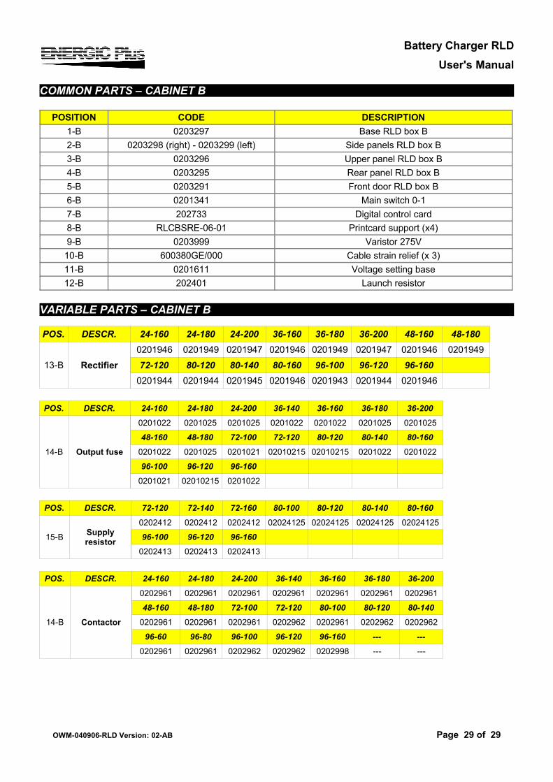
COMMON PARTS – CABINET B
POSITION CODE DESCRIPTION1-B 0203297 Base RLD box B2-B 0203298 (right) - 0203299 (left) Side panels RLD box B3-B 0203296 Upper panel RLD box B4-B 0203295 Rear panel RLD box B5-B 0203291 Front door RLD box B6-B 0201341 Main switch 0-17-B 202733 Digital control card8-B RLCBSRE-06-01 Printcard support (x4)9-B 0203999 Varistor 275V
10-B 600380GE/000 Cable strain relief (x 3)11-B 0201611 Voltage setting base12-B 202401 Launch resistor
VARIABLE PARTS – CABINET B
POS. DESCR. 24-160 24-180 24-200 36-160 36-180 36-200 48-160 48-180
13-B Rectifier0201946 0201949 0201947 0201946 0201949 0201947 0201946 0201949
72-120 80-120 80-140 80-160 96-100 96-120 96-1600201944 0201944 0201945 0201946 0201943 0201944 0201946
POS. DESCR. 24-160 24-180 24-200 36-140 36-160 36-180 36-200
14-B Output fuse
0201022 0201025 0201025 0201022 0201022 0201025 0201025
48-160 48-180 72-100 72-120 80-120 80-140 80-1600201022 0201025 0201021 02010215 02010215 0201022 0201022
96-100 96-120 96-1600201021 02010215 0201022
POS. DESCR. 72-120 72-140 72-160 80-100 80-120 80-140 80-160
15-B Supply resistor
0202412 0202412 0202412 02024125 02024125 02024125 02024125
96-100 96-120 96-1600202413 0202413 0202413
POS. DESCR. 24-160 24-180 24-200 36-140 36-160 36-180 36-200
14-B Contactor
0202961 0202961 0202961 0202961 0202961 0202961 0202961
48-160 48-180 72-100 72-120 80-100 80-120 80-1400202961 0202961 0202961 0202962 0202961 0202962 0202962
96-60 96-80 96-100 96-120 96-160 --- ---0202961 0202961 0202962 0202962 0202998 --- ---
OWM-040906-RLD Version: 02-AB Page 29 of 29