Embed Size (px)
Citation preview
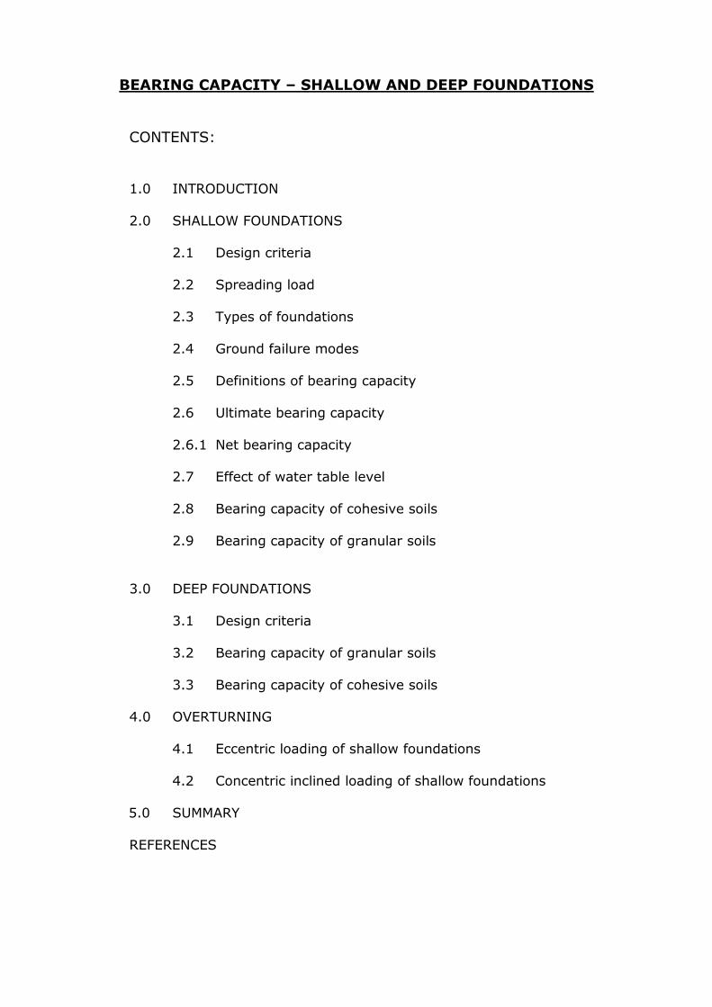
BEARING CAPACITY – SHALLOW AND DEEP FOUNDATIONS
CONTENTS:
1.0 INTRODUCTION
2.0 SHALLOW FOUNDATIONS
2.1 Design criteria 2.2 Spreading load
2.3 Types of foundations
2.4 Ground failure modes
2.5 Definitions of bearing capacity
2.6 Ultimate bearing capacity
2.6.1 Net bearing capacity
2.7 Effect of water table level
2.8 Bearing capacity of cohesive soils
2.9 Bearing capacity of granular soils
3.0 DEEP FOUNDATIONS
3.1 Design criteria
3.2 Bearing capacity of granular soils
3.3 Bearing capacity of cohesive soils
4.0 OVERTURNING
4.1 Eccentric loading of shallow foundations
4.2 Concentric inclined loading of shallow foundations
5.0 SUMMARY
REFERENCES
-2- Bearing Capacity v1.00 September 2010
1.0 INTRODUCTION
A foundation is defined as the supporting base of a structure which forms the interface across which the loads are transmitted to the underlying soil or rock. In most cases foundations in civil engineering are constructed of plain or
reinforced concrete, notable exceptions being roads, embankments and dams.
Foundations are classified according to the depth of founding, D (depth of base of foundation below ground level) compared to the width of the foundation, B.
Shallow foundations: are placed at shallow depths i.e. D B or where D is less than about 3m (i.e. within reach of normal excavation plant).
Deep foundations: are placed at greater depths i.e. D3m or DB.
Pile foundations: transmit the loads to greater depths through steel or reinforced concrete columns (see separate note set)
2.0 SHALLOW FOUNDATIONS (D<B or D<3m) NOTE: only a ‘general guide’
2.1 Design criteria
i) Adequate depth The depth of founding, D, must be sufficient to prevent conditions on the ground surface from affecting the foundation e.g. climatic changes –
rainfall, temperature, freezing/ thawing.
Also the depth must be adequate to resist: Changes resulting in ground water level movement and The effects of horizontal loads and overturning moments.
ii) Stability of the supported structure
Failure of a foundation could occur due to inadequate bearing capacity of the soil beneath the foundation (leading to shear failure), overturning or sliding of the foundation.
iii) Limiting settlement
The acceptable settlement of a structure must not be exceeded by the settlement of its foundation. Types of settlement:
Immediate (undrained settlement) Occurs during construction as dead and structural loading is
imposed. Consolidation(time dependent)
Settlement (+ differential settlement) develops during the life of a structure.
2.2 Spreading load
Shallow foundations convert a localised load (e.g. a point load transmitted by a column or a line load, such as cavity wall brick construction) into a pressure by
spreading the load over the area of a foundation.
-3- Bearing Capacity v1.00 September 2010
Thus for a column (point) load, P kN acting on a rectangular pad foundation, length, L by width, B the bearing pressure, q is given by;
q = P
kN/m2
L x B For a line load of S kN/lin m, acting on a strip foundation width, B the applied
pressure, q is given by;
q = S
kN/m2
B x 1m
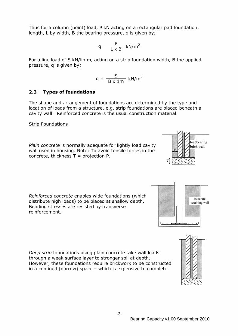
2.3 Types of foundations
The shape and arrangement of foundations are determined by the type and location of loads from a structure, e.g. strip foundations are placed beneath a
cavity wall. Reinforced concrete is the usual construction material. Strip Foundations
Plain concrete is normally adequate for lightly load cavity wall used in housing. Note: To avoid tensile forces in the concrete, thickness T = projection P.
Reinforced concrete enables wide foundations (which distribute high loads) to be placed at shallow depth.
Bending stresses are resisted by transverse reinforcement.
Deep strip foundations using plain concrete take wall loads through a weak surface layer to stronger soil at depth.
However, these foundations require brickwork to be constructed in a confined (narrow) space – which is expensive to complete.
-4- Bearing Capacity v1.00 September 2010
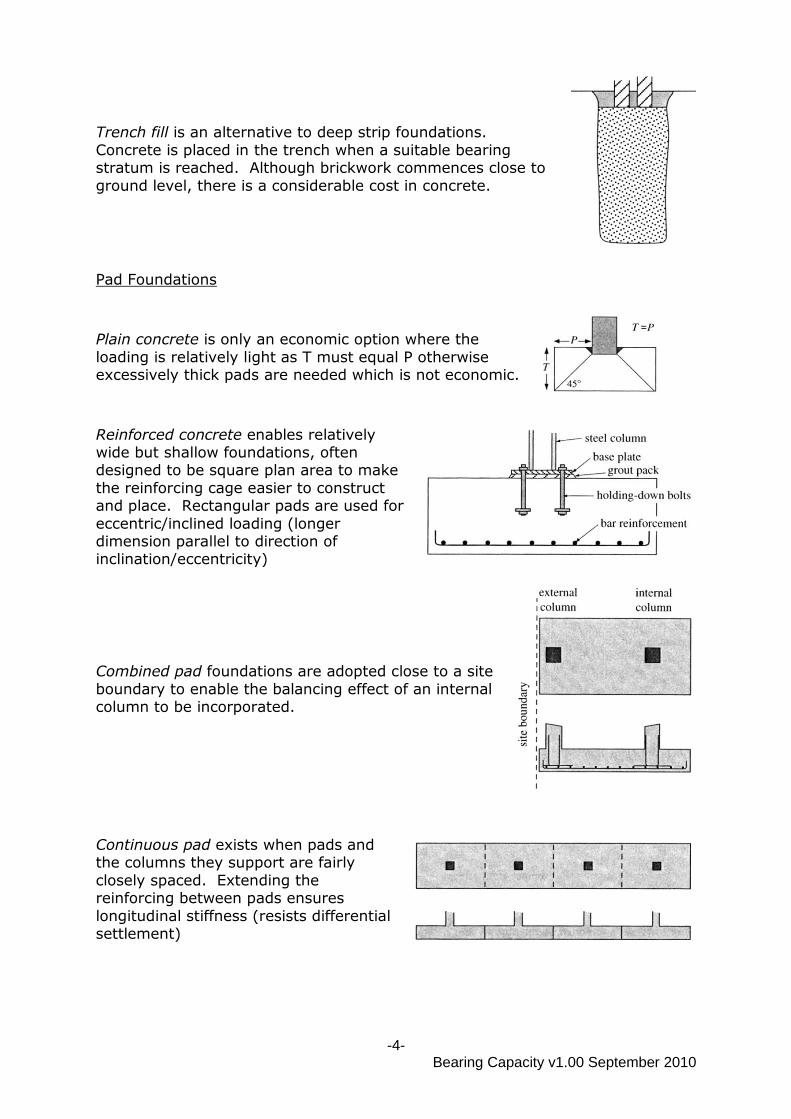
Trench fill is an alternative to deep strip foundations.
Concrete is placed in the trench when a suitable bearing stratum is reached. Although brickwork commences close to
ground level, there is a considerable cost in concrete.
Pad Foundations
Plain concrete is only an economic option where the
loading is relatively light as T must equal P otherwise excessively thick pads are needed which is not economic.
Reinforced concrete enables relatively wide but shallow foundations, often designed to be square plan area to make
the reinforcing cage easier to construct and place. Rectangular pads are used for
eccentric/inclined loading (longer dimension parallel to direction of inclination/eccentricity)
Combined pad foundations are adopted close to a site
boundary to enable the balancing effect of an internal column to be incorporated.
Continuous pad exists when pads and the columns they support are fairly
closely spaced. Extending the reinforcing between pads ensures
longitudinal stiffness (resists differential settlement)
-5- Bearing Capacity v1.00 September 2010
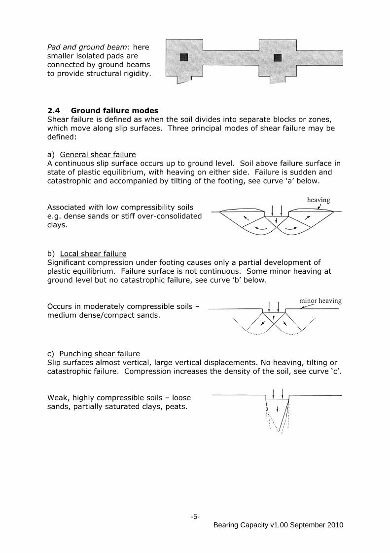
Pad and ground beam: here smaller isolated pads are connected by ground beams
to provide structural rigidity.
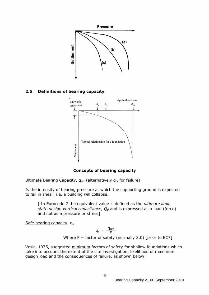
2.4 Ground failure modes Shear failure is defined as when the soil divides into separate blocks or zones,
which move along slip surfaces. Three principal modes of shear failure may be defined:
a) General shear failure A continuous slip surface occurs up to ground level. Soil above failure surface in
state of plastic equilibrium, with heaving on either side. Failure is sudden and catastrophic and accompanied by tilting of the footing, see curve „a‟ below.
Associated with low compressibility soils
e.g. dense sands or stiff over-consolidated clays.
b) Local shear failure
Significant compression under footing causes only a partial development of plastic equilibrium. Failure surface is not continuous. Some minor heaving at ground level but no catastrophic failure, see curve „b‟ below.
Occurs in moderately compressible soils – medium dense/compact sands.
c) Punching shear failure Slip surfaces almost vertical, large vertical displacements. No heaving, tilting or catastrophic failure. Compression increases the density of the soil, see curve „c‟.
Weak, highly compressible soils – loose sands, partially saturated clays, peats.
-6- Bearing Capacity v1.00 September 2010
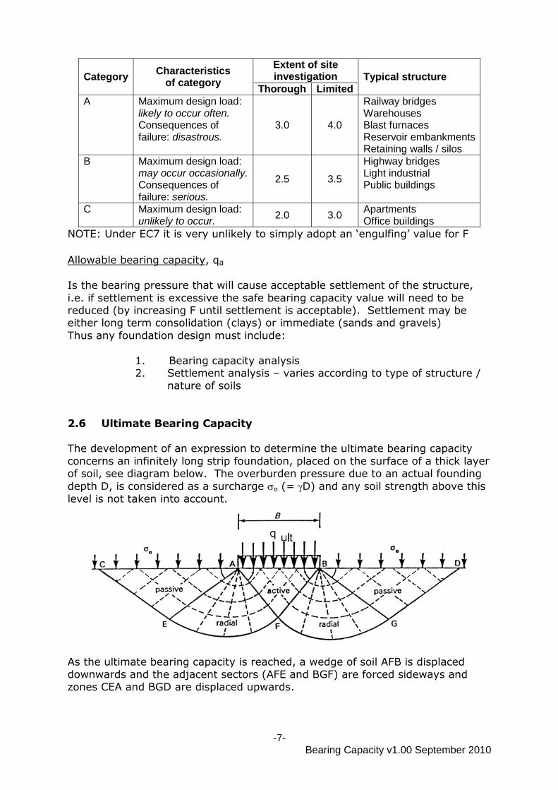
2.5 Definitions of bearing capacity
Concepts of bearing capacity
Ultimate Bearing Capacity, qult (alternatively qf, for failure)
Is the intensity of bearing pressure at which the supporting ground is expected to fail in shear, i.e. a building will collapse.
[ In Eurocode 7 the equivalent value is defined as the ultimate limit
state design vertical capacitance, Qd and is expressed as a load (force)
and not as a pressure or stress].
Safe bearing capacity, qs
qs = qult
F Where F = factor of safety (normally 3.0) [prior to EC7]
Vesic, 1975, suggested minimum factors of safety for shallow foundations which take into account the extent of the site investigation, likelihood of maximum
design load and the consequences of failure, as shown below;
-7- Bearing Capacity v1.00 September 2010
Category Characteristics
of category
Extent of site investigation Typical structure
Thorough Limited
A Maximum design load: likely to occur often. Consequences of failure: disastrous.
3.0 4.0
Railway bridges Warehouses Blast furnaces Reservoir embankments Retaining walls / silos
B Maximum design load: may occur occasionally. Consequences of failure: serious.
2.5 3.5
Highway bridges Light industrial Public buildings
C Maximum design load: unlikely to occur.
2.0 3.0 Apartments Office buildings
NOTE: Under EC7 it is very unlikely to simply adopt an „engulfing‟ value for F
Allowable bearing capacity, qa
Is the bearing pressure that will cause acceptable settlement of the structure,
i.e. if settlement is excessive the safe bearing capacity value will need to be reduced (by increasing F until settlement is acceptable). Settlement may be either long term consolidation (clays) or immediate (sands and gravels)
Thus any foundation design must include:
1. Bearing capacity analysis 2. Settlement analysis – varies according to type of structure /
nature of soils
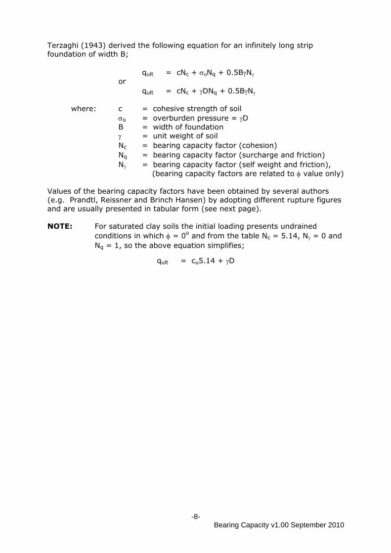
2.6 Ultimate Bearing Capacity The development of an expression to determine the ultimate bearing capacity
concerns an infinitely long strip foundation, placed on the surface of a thick layer of soil, see diagram below. The overburden pressure due to an actual founding
depth D, is considered as a surcharge o (= D) and any soil strength above this level is not taken into account.
As the ultimate bearing capacity is reached, a wedge of soil AFB is displaced downwards and the adjacent sectors (AFE and BGF) are forced sideways and zones CEA and BGD are displaced upwards.
-8- Bearing Capacity v1.00 September 2010
Terzaghi (1943) derived the following equation for an infinitely long strip foundation of width B;
qult = cNc + oNq + 0.5BN or
qult = cNc + DNq + 0.5BN
where: c = cohesive strength of soil
o = overburden pressure = D
B = width of foundation
= unit weight of soil
Nc = bearing capacity factor (cohesion)
Nq = bearing capacity factor (surcharge and friction)
N = bearing capacity factor (self weight and friction),
(bearing capacity factors are related to value only)
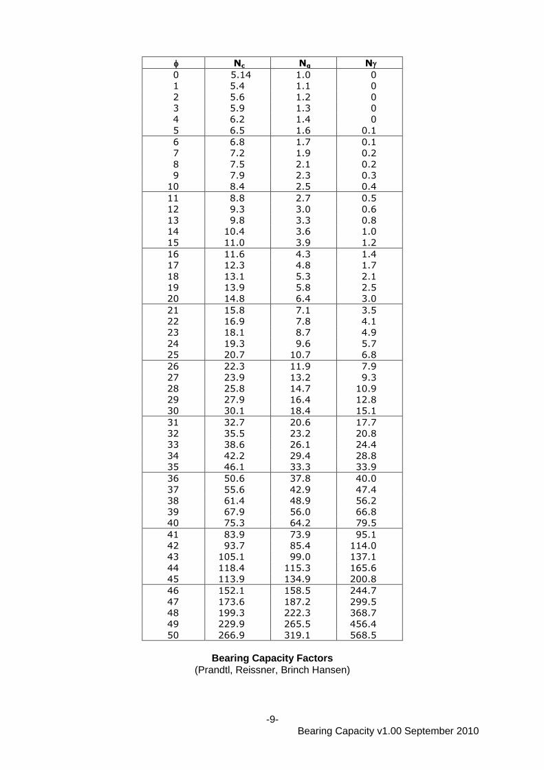
Values of the bearing capacity factors have been obtained by several authors (e.g. Prandtl, Reissner and Brinch Hansen) by adopting different rupture figures
and are usually presented in tabular form (see next page). NOTE: For saturated clay soils the initial loading presents undrained
conditions in which = 0o and from the table Nc = 5.14, N = 0 and
Nq = 1, so the above equation simplifies;
qult = cu5.14 + D
-9- Bearing Capacity v1.00 September 2010
Nc Nq N
0 5.14 1.0 0
1 5.4 1.1 0
2 5.6 1.2 0
3 5.9 1.3 0
4 6.2 1.4 0
5 6.5 1.6 0.1
6 6.8 1.7 0.1
7 7.2 1.9 0.2
8 7.5 2.1 0.2
9 7.9 2.3 0.3
10 8.4 2.5 0.4
11 8.8 2.7 0.5
12 9.3 3.0 0.6
13 9.8 3.3 0.8
14 10.4 3.6 1.0
15 11.0 3.9 1.2
16 11.6 4.3 1.4
17 12.3 4.8 1.7
18 13.1 5.3 2.1
19 13.9 5.8 2.5
20 14.8 6.4 3.0
21 15.8 7.1 3.5
22 16.9 7.8 4.1
23 18.1 8.7 4.9
24 19.3 9.6 5.7
25 20.7 10.7 6.8
26 22.3 11.9 7.9
27 23.9 13.2 9.3
28 25.8 14.7 10.9
29 27.9 16.4 12.8
30 30.1 18.4 15.1
31 32.7 20.6 17.7
32 35.5 23.2 20.8
33 38.6 26.1 24.4
34 42.2 29.4 28.8
35 46.1 33.3 33.9
36 50.6 37.8 40.0
37 55.6 42.9 47.4
38 61.4 48.9 56.2
39 67.9 56.0 66.8
40 75.3 64.2 79.5
41 83.9 73.9 95.1
42 93.7 85.4 114.0
43 105.1 99.0 137.1
44 118.4 115.3 165.6
45 113.9 134.9 200.8
46 152.1 158.5 244.7
47 173.6 187.2 299.5
48 199.3 222.3 368.7
49 229.9 265.5 456.4
50 266.9 319.1 568.5
Bearing Capacity Factors
(Prandtl, Reissner, Brinch Hansen)
-10- Bearing Capacity v1.00 September 2010
2.6.1 Net Bearing Capacity, qn or qnet
Soil excavated to depth, D in order to construct a foundation, causes a relief in
vertical stress of D. If the excavation is subsequently backfilled the overburden
pressure, o, is restored and net bearing capacity applies.
For example, net ultimate bearing capacity, qn ult ,is the net change in total
stress experienced by the soil at the base of the foundation i.e.;
qn ult = (total applied stress) – (stress removed due to the excavation)
qn ult = qult - o
= qult - D
The factor of safety, F must be applied to the net and not the gross ultimate
bearing capacity;
qs = qult - D
+ D F
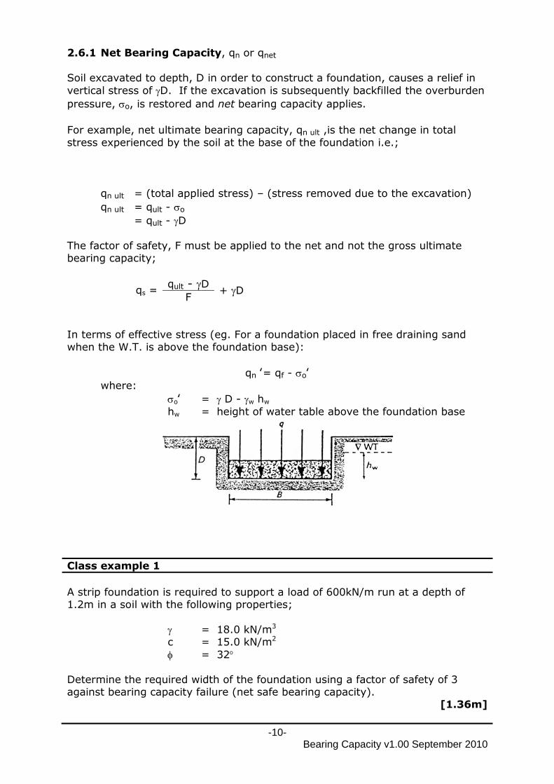
In terms of effective stress (eg. For a foundation placed in free draining sand
when the W.T. is above the foundation base):
qn ‛= qf - o‛ where:
o‛ = D - w hw
hw = height of water table above the foundation base
Class example 1
A strip foundation is required to support a load of 600kN/m run at a depth of 1.2m in a soil with the following properties;
= 18.0 kN/m3 c = 15.0 kN/m2
= 32
Determine the required width of the foundation using a factor of safety of 3 against bearing capacity failure (net safe bearing capacity).
[1.36m]
-11- Bearing Capacity v1.00 September 2010
In the above analysis, the foundation was assumed to be infinitely long. In order to use the expression for practical design purposes, three shape categories are
defined: strip rectangular
circular ≡ square
Consequently the Terzaghi equation changes to:
qult = cNcsc + DNqsq + 0.5BNs
And in terms of net ultimate bearing capacity, qn ult :
qn ult = cNcsc + DNq sq + 0.5BNs - D
where sc , sq and s are shape factors (Vesic, 1975):
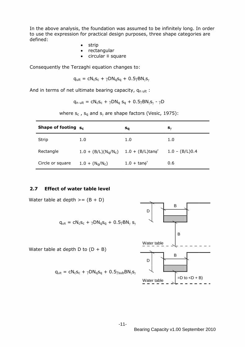
2.7 Effect of water table level
Water table at depth >= (B + D)
qult = cNcsc + DNqsq + 0.5BN s
D
B
B
Water table
Water table at depth D to (D + B)
qult = cNcsc + DNqsq + 0.5subBNs
D
B
Water table
=D to <D + B)
Shape of footing sc sq sγ
Strip 1.0 1.0 1.0
Rectangle 1.0 + (B/L)(Nq/Nc) 1.0 + (B/L)tan‛ 1.0 – (B/L)0.4
Circle or square 1.0 + (Nq/Nc) 1.0 + tan‛ 0.6
-12- Bearing Capacity v1.00 September 2010
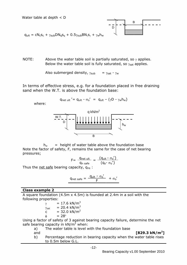
Water table at depth < D
qult = cNcsc + subDNqsq + 0.5subBNs + whw
B
D
NOTE: Above the water table soil is partially saturated, so applies.
Below the water table soil is fully saturated, so sat applies.
Also submerged density, sub = sat - w
In terms of effective stress, e.g. for a foundation placed in free draining
sand when the W.T. is above the foundation base:
qnet ult ‛= qult - o‛ = qult – (D - whw) where:
q kN/m2
W.T.
D hw
B
hw = height of water table above the foundation base
Note the factor of safety, F, remains the same for the case of net bearing pressures;
F= qnet ult
= (qult - o‛)
qn safe (qs- o‛)
Thus the net safe bearing capacity, qns :
qnet safe = qult - o‛
+ o‛ F
Class example 2
A square foundation (4.5m x 4.5m) is founded at 2.4m in a soil with the following properties:
= 17.6 kN/m3
sat = 20.4 kN/m3 c = 32.0 kN/m2
= 28 Using a factor of safety of 3 against bearing capacity failure, determine the net
safe bearing capacity in kN/m2 when: a) The water table is level with the foundation base
and [829.3 kN/m2]
b) Percentage reduction in bearing capacity when the water table rises to 0.5m below G.L.
-13- Bearing Capacity v1.00 September 2010
[15.8%]
2.8 Bearing capacity of cohesive soils
The ultimate bearing capacity of saturated cohesive soils (clay and silt) with low permeability is most critical immediately after construction, before the excess
porewater pressure has had time to dissipate i.e. undrained conditions. As time proceeds, consolidation occurs, the soil becomes stiffer and has more strength.
Therefore design of foundations on fine grained soils should be in terms of undrained or total stress.
Skempton (1951) suggested for an undrained saturated clay (u = 0o), the basic Terzaghi equation should be used, but with values of Nc related to the shape and
depth of the foundation;
qult = cNc + DNq + 0.5BN
Since when = 0o; Nq = 1 and N = 0
Terzaghi becomes;
qult = cuNc + D
And in net terms;
qn ult = cuNc + D - D = cuNc
Values of Nc can be found from the chart (Skempton, 1951) below:
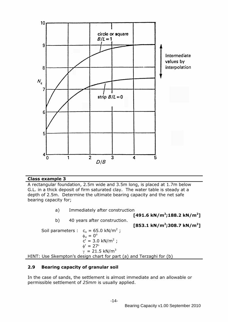
-14- Bearing Capacity v1.00 September 2010
Class example 3
A rectangular foundation, 2.5m wide and 3.5m long, is placed at 1.7m below
G.L. in a thick deposit of firm saturated clay. The water table is steady at a depth of 2.5m. Determine the ultimate bearing capacity and the net safe bearing capacity for;
a) Immediately after construction
[491.6 kN/m2;188.2 kN/m2] b) 40 years after construction.
[853.1 kN/m2;308.7 kN/m2]
Soil parameters : cu = 65.0 kN/m2 ;
u = 0o
c‛ = 3.0 kN/m2 ;
‛ = 27
= 21.5 kN/m3
HINT: Use Skempton‟s design chart for part (a) and Terzaghi for (b)
2.9 Bearing capacity of granular soil
In the case of sands, the settlement is almost immediate and an allowable or permissible settlement of 25mm is usually applied.
-15- Bearing Capacity v1.00 September 2010
Foundation design uses the allowable bearing capacity, qa, which satisfies the
settlement condition and provides values of the Factor of Safety greater than the normal 3.0 – 4.0.
Because of the difficulty and expense of undisturbed sampling and lack of uniformity of sand/gravel deposits, in-situ test results are used to determine the
allowable bearing capacity and to make settlement predictions.
In-situ (on-site) tests: 1. Plate bearing test
2. Standard penetration test (SPT) – sand/gravel beds 3. Dutch cone test – not used much in UK due to stony nature of ground
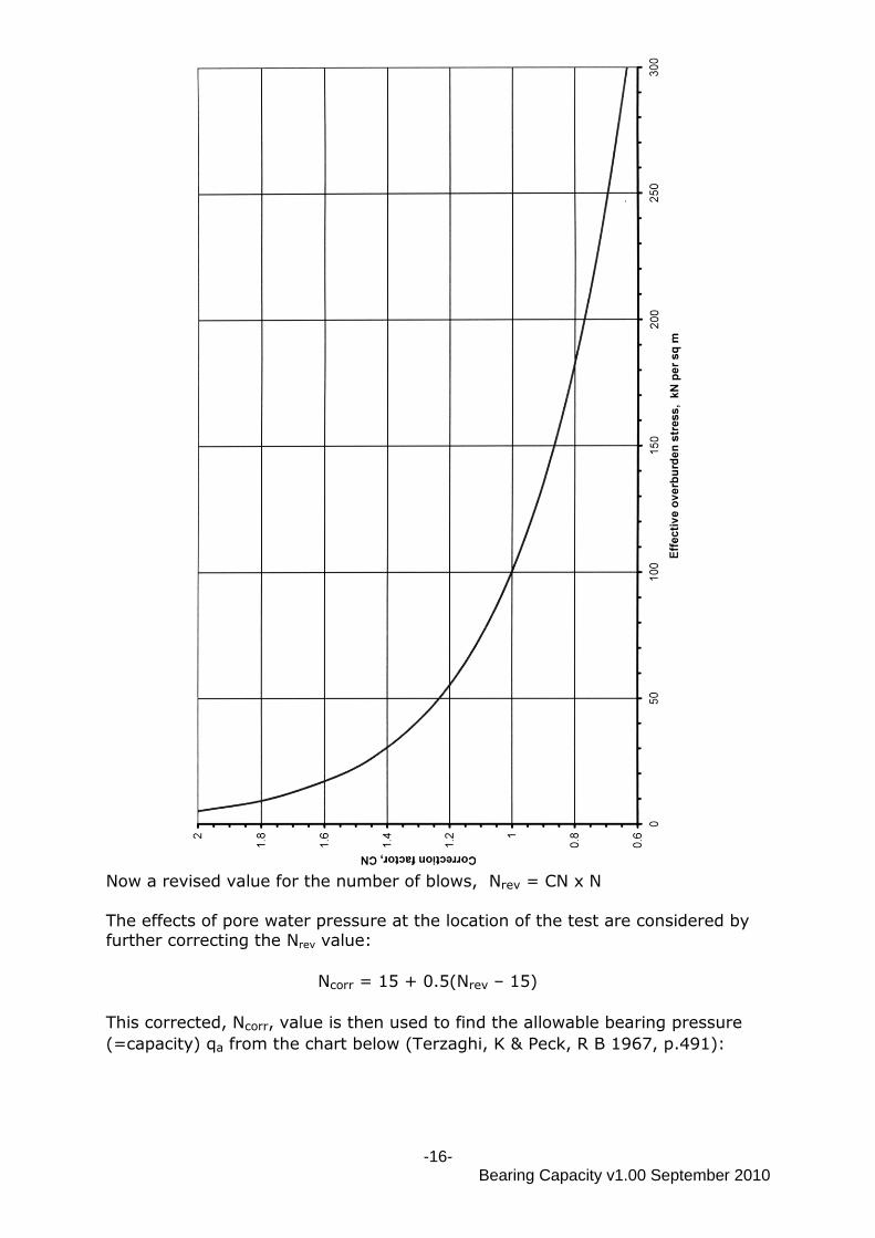
The standard penetration test results, N values, are corrected to allow for;
pore water pressure and overburden pressure
and are then used to find the allowable bearing capacity, qa, from a chart.
Correction factor, CN, for overburden pressure – this accounts for the confining pressure at the depth at which the N value has been taken and is read off a
graph (Peck, Hanson & Thornburn, 1974):
-16- Bearing Capacity v1.00 September 2010
Now a revised value for the number of blows, Nrev = CN x N
The effects of pore water pressure at the location of the test are considered by further correcting the Nrev value:
Ncorr = 15 + 0.5(Nrev – 15)
This corrected, Ncorr, value is then used to find the allowable bearing pressure
(=capacity) qa from the chart below (Terzaghi, K & Peck, R B 1967, p.491):
-17- Bearing Capacity v1.00 September 2010
The effect of the water table may be taken into account by applying the following correction:
Cw = 0.5 {1 + Dw
} (D + B)
where
Dw = depth of water table below ground level
D = depth of foundation below ground level
B = width of foundation
Thus, allowable bearing pressure, qa derived from the previous graph becomes a
corrected allowable bearing pressure, qa corr;
qa corr = Cw qa
(from graph)
-18- Bearing Capacity v1.00 September 2010
Class example 4
A 3.0m square foundation is located at a depth of 1.8m in uniform sand,
( = 18.6 kN/m3 ; sat = 20.5 kN/m3). A site investigation revealed SPT values between 1.8m and 4.8m below ground level as shown below. Initially the water table level is steady at 3.5 m below ground level.
Depth (m) N 1.8 10
2.8 13 3.8 17
4.8 20
If the water table then rises to 0.9m below ground level, determine the percentage reduction in the allowable bearing capacity for a maximum settlement of 25mm.
[37%]
3.0 DEEP FOUNDATIONS (DB or D3m)
3.1 Design criteria If the ultimate bearing capacity of a deep foundation is estimated using
Terzaghi‟s equation for shallow foundations, the ultimate bearing capacity will be grossly under-estimated.
Meyerhof produced equations for the ultimate bearing capacity for deep foundations:
Strip Foundation
qult = cNc + PoNq + 0.5BN
Rectangular Foundation
qult = c Nc(1 + 0.2 B
) + PoNq + 0.5BN(1 – 0.2 B
) L L
Where;
Nc , Nq and N = bearing capacity factors
(symbols same as for shallow foundations)
Po = average lateral pressure acting against the
vertical face of the foundation over the height “h” above the base of the plastic failure zone
(see below).
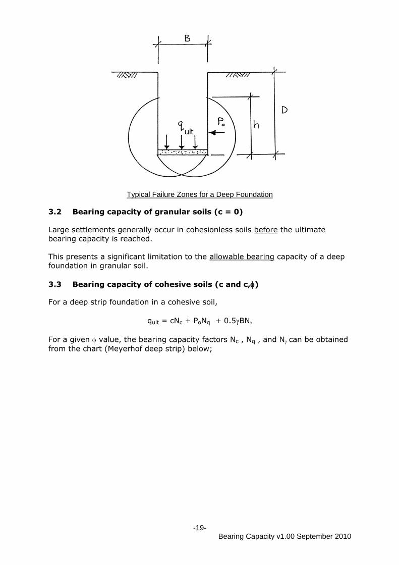
-19- Bearing Capacity v1.00 September 2010
Typical Failure Zones for a Deep Foundation
3.2 Bearing capacity of granular soils (c = 0)
Large settlements generally occur in cohesionless soils before the ultimate
bearing capacity is reached. This presents a significant limitation to the allowable bearing capacity of a deep
foundation in granular soil.
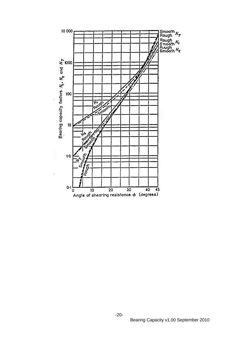
3.3 Bearing capacity of cohesive soils (c and c,)
For a deep strip foundation in a cohesive soil,
qult = cNc + PoNq + 0.5BN
For a given value, the bearing capacity factors Nc , Nq , and N can be obtained
from the chart (Meyerhof deep strip) below;
-20- Bearing Capacity v1.00 September 2010
-21- Bearing Capacity v1.00 September 2010
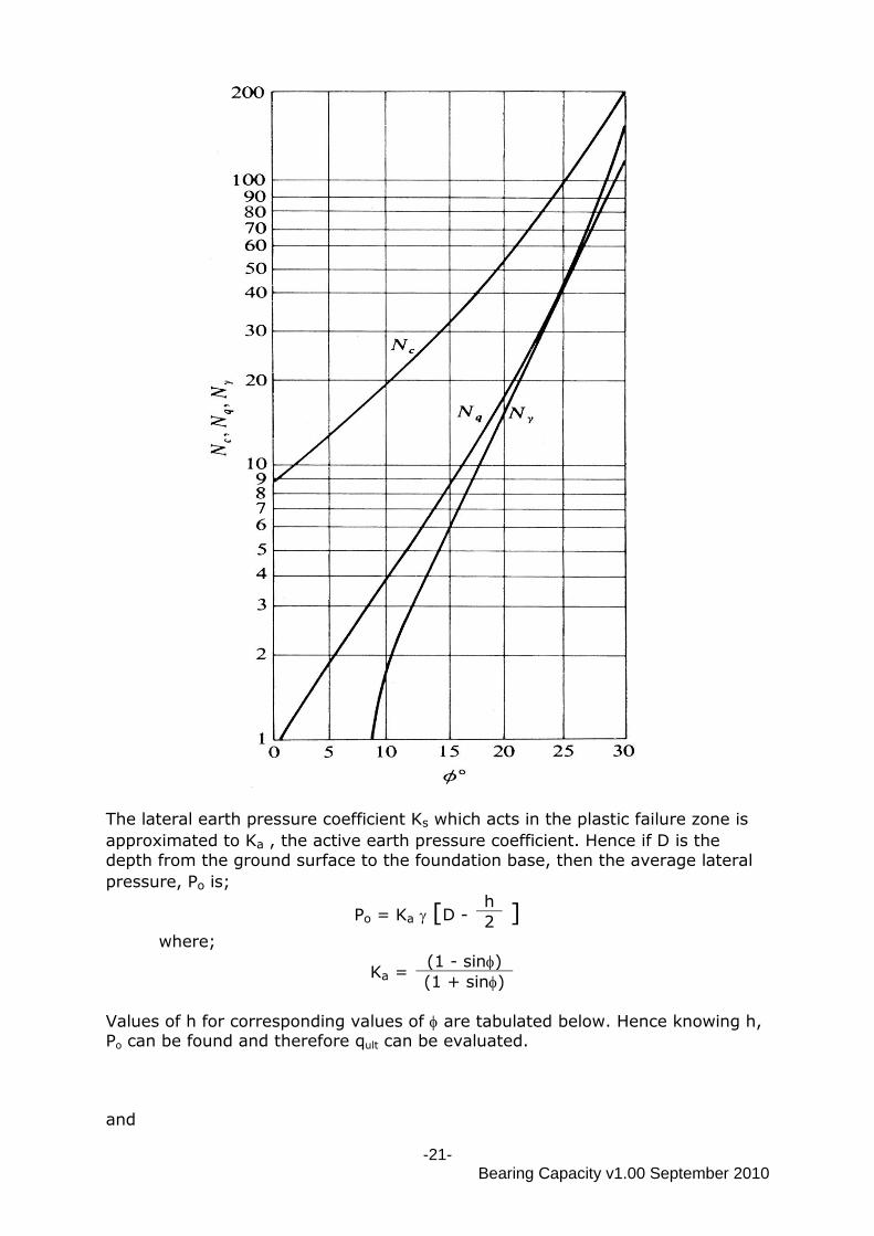
The lateral earth pressure coefficient Ks which acts in the plastic failure zone is
approximated to Ka , the active earth pressure coefficient. Hence if D is the
depth from the ground surface to the foundation base, then the average lateral
pressure, Po is;
Po = Ka [D - h
] 2 where;
Ka = (1 - sin)
(1 + sin)
Values of h for corresponding values of are tabulated below. Hence knowing h, Po can be found and therefore qult can be evaluated.
and
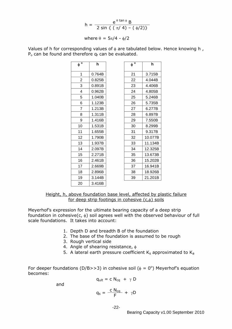
-22- Bearing Capacity v1.00 September 2010
h = e
tan B
2 sin { ( / 4) – ( /2)}
where = 5/4 - /2
Values of h for corresponding values of are tabulated below. Hence knowing h ,
Po can be found and therefore qf can be evaluated.
o
h o
h
1 0.764B 21 3.715B
2 0.825B 22 4.044B
3 0.891B 23 4.406B
4 0.962B 24 4.805B
5 1.040B 25 5.246B
6 1.123B 26 5.735B
7 1.213B 27 6.277B
8 1.311B 28 6.897B
9 1.416B 29 7.550B
10 1.531B 30 8.299B
11 1.655B 31 9.317B
12 1.790B 32 10.077B
13 1.937B 33 11.134B
14 2.097B 34 12.325B
15 2.271B 35 13.673B
16 2.461B 36 15.202B
17 2.669B 37 16.941B
18 2.896B 38 18.926B
19 3.144B 39 21.201B
20 3.416B
Height, h, above foundation base level, affected by plastic failure
for deep strip footings in cohesive (c,) soils Meyerhof‟s expression for the ultimate bearing capacity of a deep strip
foundation in cohesive(c, ) soil agrees well with the observed behaviour of full scale foundations. It takes into account:
1. Depth D and breadth B of the foundation 2. The base of the foundation is assumed to be rough
3. Rough vertical side
4. Angle of shearing resistance,
5. A lateral earth pressure coefficient Ks approximated to Ka
For deeper foundations (D/B>>3) in cohesive soil ( = 0o) Meyerhof‟s equation becomes:
qult = c Ncq + D
and
qs = c Ncq + D
F
-23- Bearing Capacity v1.00 September 2010
where Ncq is a bearing capacity factor based on foundation
shape and roughness; = 10.18 circular foundation, (rough)
= 9.52 circular foundation, (smooth) = 8.85 strip foundation, (rough) = 8.28 strip foundation, (smooth)
Class example 5
A rectangular foundation (2.0m x 6.0m ) is placed at 15m below ground level in
a sandy clay soil (sat =21.3 kN/m3 ; c = 35.0 kN/m
2 ; = 25). The water table
is steady at ground level. If the shaft and base of the foundation are smooth, determine the net safe
bearing capacity of the foundation.
Adopt a factor of safety of 3 against bearing capacity failure. [2345.8 kN/m2]
4.0 OVERTURNING
So far only vertical concentric loading of the foundation has been considered. Many foundations have to be designed to cater for the effects of horizontal loading and moment loading as a result of eccentric or inclined loads.
The analysis involves resolving the loading into a single vertical load acting at
the base of the foundation at some eccentricity, e, from the centroid of the foundation. If a horizontal load exists, it is considered to act at the foundation base level, where it no longer contributes to the overturning moment but
provides a resultant inclined loading.
Applying inclined and eccentric/concentric loads to a foundation with a horizontal
base, leads to a reduction in the ultimate bearing capacity, qult, compared with
the value obtained for vertical loading. Brinch Hansen (1970) developed a solution for eccentric and inclined loading for
shallow and deep strip footings for all conditions.
Meyerhof (1953) developed a solution (based on strip footing theory) for concentric inclined loading of shallow, circular, square and rectangular
foundations for = 0 conditions.
4.1 Eccentric loading of a strip foundation (Brinch Hansen, 1970)
This method uses a reduced foundation width, B‛ and an equivalent vertical
pressure, Pv.
If “e” is the eccentricity of the resultant load measured from the axis of symmetry of the
foundation, then an effective foundation width B‛ for bearing capacity considerations is given by:
B‛ = B - 2e where B is the actual width.
-24- Bearing Capacity v1.00 September 2010
The equivalent vertical pressure, qe , is given by:
qe = Pv + Ph
B‛
where:
Pv = vertical load component/metre run
Ph = horizontal load component/metre run
B‛ = effective width of base/metre run
= dimensionless constant – related to ‛
tan‛
F 0.0 0.2 0.4 0.6 0.8 1.0
1.4 1.8 2.3 2.8 3.3 3.9
where F is a factor of safety against bearing capacity failure.
Now,
qe qs
For cohesive soil ( = 0o) use;
qs = cu Nc + D
F
where Nc is related to D/ B‛ and is found from
Skempton‟s graph for = 0o
For c, soil use;
Use Terzaghi (qult = cNc + DNq+ 0.5 B‛N)
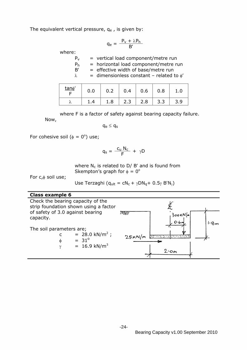
Class example 6
Check the bearing capacity of the strip foundation shown using a factor
of safety of 3.0 against bearing capacity.
The soil parameters are; c = 28.0 kN/m2 ;
= 31o
= 16.9 kN/m3
-25- Bearing Capacity v1.00 September 2010
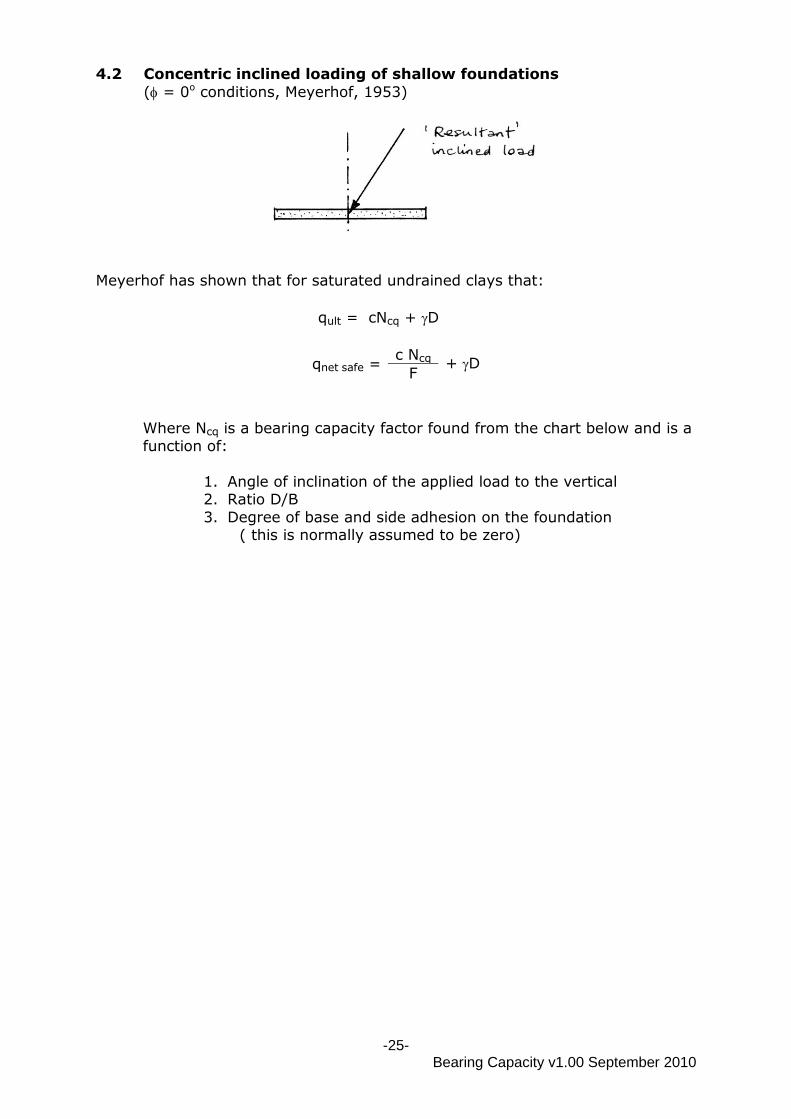
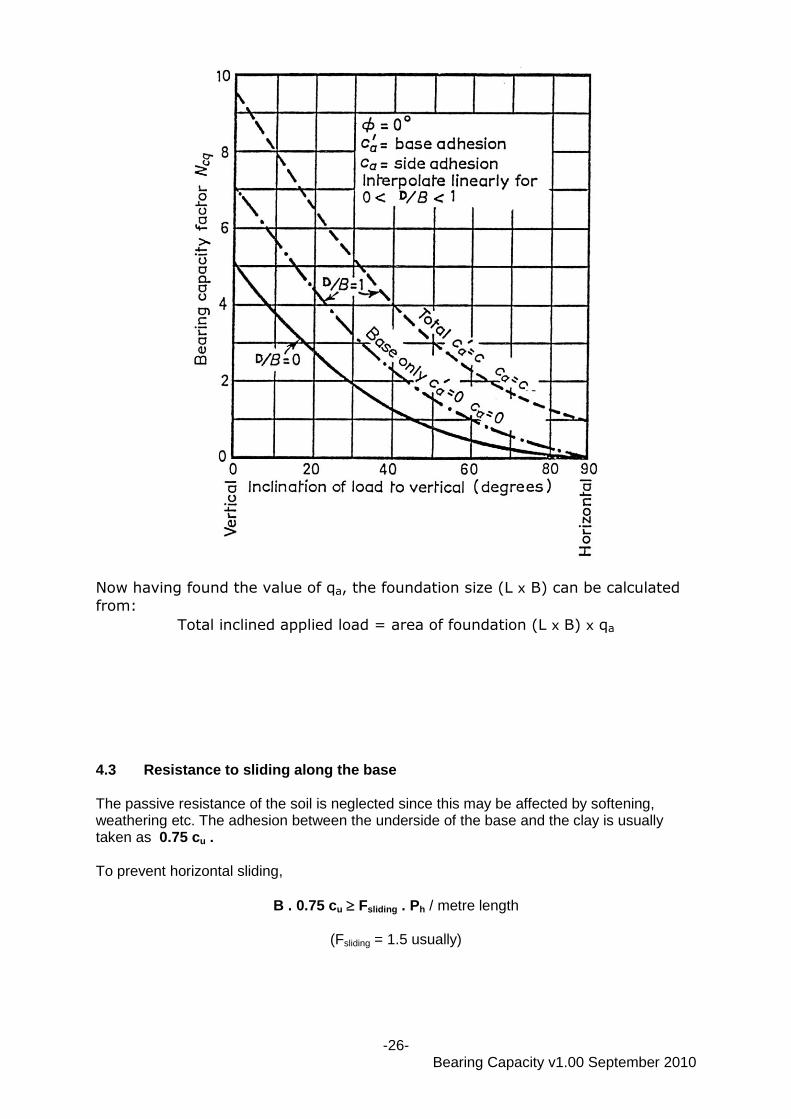
4.2 Concentric inclined loading of shallow foundations
( = 0o conditions, Meyerhof, 1953)
Meyerhof has shown that for saturated undrained clays that:
qult = cNcq + D
qnet safe = c Ncq + D
F
Where Ncq is a bearing capacity factor found from the chart below and is a
function of:
1. Angle of inclination of the applied load to the vertical 2. Ratio D/B
3. Degree of base and side adhesion on the foundation ( this is normally assumed to be zero)
-26- Bearing Capacity v1.00 September 2010
Now having found the value of qa, the foundation size (L x B) can be calculated
from:
Total inclined applied load = area of foundation (L x B) x qa
4.3 Resistance to sliding along the base The passive resistance of the soil is neglected since this may be affected by softening, weathering etc. The adhesion between the underside of the base and the clay is usually taken as 0.75 cu . To prevent horizontal sliding,
B . 0.75 cu Fsliding . Ph / metre length
(Fsliding = 1.5 usually)
-27- Bearing Capacity v1.00 September 2010
4.4 Design of heel rib If for economic reasons, a wide base is not selected to counteract sliding, a heel rib may be included in the design.
1. Depth d = balance of resistance to sliding 2/3 qa = { F.Ph – 0.75 cu B } 2/3 qa 2. B.M. at junction of rib with heel = { F.Ph – 0.75 cu B } d Ast 2 3. Check shear and bond.
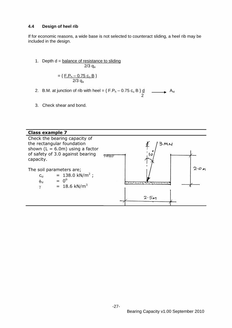
Class example 7
Check the bearing capacity of the rectangular foundation
shown (L = 6.0m) using a factor of safety of 3.0 against bearing
capacity.
The soil parameters are;
cu = 138.0 kN/m2 ;
u = 0o
= 18.6 kN/m3
-28- Bearing Capacity v1.00 September 2010
5.0 SUMMARY
qult = ultimate bearing capacity
qs = safe bearing capacity
qs = qult
F
where F = factor of safety (normally 3.0)
qn = net bearing capacity
= qult - o = qult - D (total stress)
= qult - o‛ = qult – (D - w hw) (effective stress)
qn a = net allowable bearing capacity
qn a = qult - D
+ D F
Shallow Foundations D B ; D 3m
c , soil
Terzaghi: qult = cNcsc + DNqsq + 0.5BNs
[Nc ; Nq ; N ; sc ; sq ; s
are from tables]
- modified when W.T. is present using sub = sat - w
c soil ( =0o)
Skempton: qf = cNc + D [Nc from graph]
soil (c = 0)
qa from graph using corrected S.P.T. (N) values
Deep foundations DB ; D3m
c , soil Meyerhof :
Strip;
qult = cNc + PoNq + 0.5BN
Rectangular;
qult = c (1 + 0.2 B
)Nc + PoNq + 0.5B(1 – 0.2 B
)N L L
[Nc ; Nq ; N from graph
Po = Ka[ D – (h/2) ]
h from table
Ka = (1-sin)/(1+sin)]
c soil ( = 0 o)
Meyerhof : qult = cuNcq + D [Ncq values given]
soil (c = 0 o)
Meyerhof : qult = 0.5BNq [Nq from graph]
Eccentric Loading – strip foundation
-29- Bearing Capacity v1.00 September 2010
Brinch Hansen : qe qa ;
qe = Pv + Ph
B‛
[ from table]
qs = cu Nc
+ D F
B‛ = B + 2e
- for c soil: Nc from Skempton
- for c, soil: Nc Nq N from table
Inclined Loading
Meyerhof : qult = cNcq + D [Ncq from graph]
REFERENCES
Brinch Hansen, J (1970) A revised and extended formula for bearing capacity
Bulletin No.28, Danish Geotechnical Institute, Copenhagen, pp5-11 Meyerhof, G G (1951) The ultimate bearing capacity of foundations
Geotechnique v2 no.4
Meyerhof, G G (1953) The bearing capacity of foundations under eccentric and inclined loads Proc 3rd International Conference on Soil Mechanics and Foundation Engineering, Zurich, vol 1 pp 440-45
Peck, R B Hanson, W E & Thornburn, T H (1974) Foundation engineering Pub:
John Wiley, New York Skempton, A W (1951) The bearing capacity of clays Proc Building Research
Congress, vol.1, pp.180-189
Terzaghi, K (1943) Theorectical soil mechanics Pub. John Wiley& Sons New York Terzaghi, K & Peck, R B (1967) Soil mechanics in engineering practice 2nd Ed
Pub. John Wiley& Sons
Vesic, A S (1975) Bearing capacity of shallow foundations. In Foundation Engineering Handbook, Ed. Winterkorn, H F and Fang, H Y. Pub: Van
Nostrand Reinhold Co.