Embed Size (px)
Citation preview
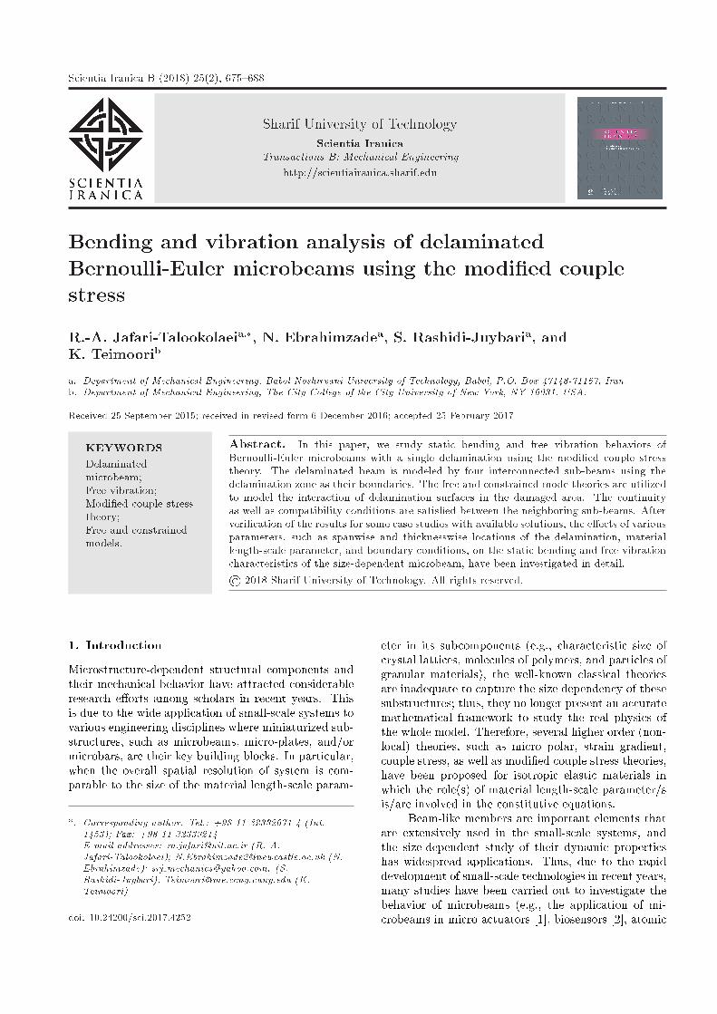
Scientia Iranica B (2018) 25(2), 675{688
Sharif University of TechnologyScientia Iranica
Transactions B: Mechanical Engineeringhttp://scientiairanica.sharif.edu
Bending and vibration analysis of delaminatedBernoulli-Euler microbeams using the modi�ed couplestress
R.-A. Jafari-Talookolaeia;�, N. Ebrahimzadea, S. Rashidi-Juybaria, andK. Teimoorib
a. Department of Mechanical Engineering, Babol Noshirvani University of Technology, Babol, P.O. Box 47148-71167, Iran.b. Department of Mechanical Engineering, The City College of the City University of New York, NY 10031, USA.
Received 25 September 2015; received in revised form 6 December 2016; accepted 25 February 2017
KEYWORDSDelaminatedmicrobeam;Free vibration;Modi�ed couple stresstheory;Free and constrainedmodels.
Abstract. In this paper, we study static bending and free vibration behaviors ofBernoulli-Euler microbeams with a single delamination using the modi�ed couple stresstheory. The delaminated beam is modeled by four interconnected sub-beams using thedelamination zone as their boundaries. The free and constrained mode theories are utilizedto model the interaction of delamination surfaces in the damaged area. The continuityas well as compatibility conditions are satis�ed between the neighboring sub-beams. Afterveri�cation of the results for some case studies with available solutions, the e�ects of variousparameters, such as spanwise and thicknesswise locations of the delamination, materiallength-scale parameter, and boundary conditions, on the static bending and free vibrationcharacteristics of the size-dependent microbeam, have been investigated in detail.© 2018 Sharif University of Technology. All rights reserved.
1. Introduction
Microstructure-dependent structural components andtheir mechanical behavior have attracted considerableresearch e�orts among scholars in recent years. Thisis due to the wide application of small-scale systems tovarious engineering disciplines where miniaturized sub-structures, such as microbeams, micro-plates, and/ormicrobars, are their key building blocks. In particular,when the overall spatial resolution of system is com-parable to the size of the material length-scale param-
*. Corresponding author. Tel.: +98 11 32332071-4 (Int.1453); Fax: +98 11 32339214E-mail addresses: [email protected] (R.-A.Jafari-Talookolaei); [email protected] (N.Ebrahimzade); srj [email protected]. (S.Rashidi-Juybari); [email protected] (K.Teimoori)
doi: 10.24200/sci.2017.4252
eter in its subcomponents (e.g., characteristic size ofcrystal lattices, molecules of polymers, and particles ofgranular materials), the well-known classical theoriesare inadequate to capture the size dependency of thesesubstructures; thus, they no longer present an accuratemathematical framework to study the real physics ofthe whole model. Therefore, several higher order (non-local) theories, such as micro polar, strain gradient,couple stress, as well as modi�ed couple stress theories,have been proposed for isotropic elastic materials inwhich the role(s) of material length-scale parameter/sis/are involved in the constitutive equations.
Beam-like members are important elements thatare extensively used in the small-scale systems, andthe size-dependent study of their dynamic propertieshas widespread applications. Thus, due to the rapiddevelopment of small-scale technologies in recent years,many studies have been carried out to investigate thebehavior of microbeams (e.g., the application of mi-crobeams in micro actuators [1], biosensors [2], atomic
676 R.-A. Jafari-Talookolaei et al./Scientia Iranica, Transactions B: Mechanical Engineering 25 (2018) 675{688
force microscopes [3], and carrying micro-particles [4]).In this regard, the couple stress elasticity theorywas presented in 1960s for the �rst time where thismodel introduced two higher-order material length-scale parameters, in addition to the two classical Lam�econstants, in the governing equations of motion [5,6].In 2002, this model was modi�ed by Yang et al. [7]to develop the modi�ed couple stress theory in whichthe constitutive equations contain only one additionalmaterial length scale, creating symmetric couple stresstensor. These two properties of the modi�ed couplestress theory (i.e., the inclusion of a symmetric couplestress tensor and the involvement of only one length-scale parameter) are two advantages of this model overthe classical couple stress theory. Therefore, in the pastdecade, many researchers have studied the behavior ofmicrobeams based on this novel and convenient theory.For instance, modi�ed couple stress theory for bendinganalysis of Bernoulli-Euler beams was presented usingthe minimum total potential energy principle [8]. Maet al. [9] developed size-dependent Timoshenko beammodel based on the modi�ed couple stress theory.They also investigated the Poisson's e�ect on the staticbending and free vibration of a simply supported beam.However, later, it was shown that considering Poisson'se�ect can lead to erroneous results, and the resultsobtained by omitting Poisson's e�ect are much closerto the experimental data [10,11]. Kahrobaiyan etal. [12] used modi�ed couple stress theory to obtainthe dynamic characteristics of atomic force microscopescantilevers. Asghari et al. investigated the static andfree vibration analyses of nonlinear Timoshenko beambased on the modi�ed couple stress theory [13]. Akg�ozand Civalek reported on the stability of axially loadedmicrobeams based on the strain gradient elasticityand modi�ed couple stress theory [14]. Simsek andReddy [15] examined the static and dynamic behaviorsof the functionally graded microbeams based on themodi�ed couple stress theory, compared with othernonlocal beam theories. Akg�oz et al. studied the vi-bration responses of non-homogenous and non-uniformmicrobeams within the framework of Bernoulli-Eulerbeam model and modi�ed couple stress theory [16]. Inaddition, Mohammad Abadi and Daneshmehr inves-tigated the buckling analyses of laminated compositebeams based on the Bernoulli-Euler and Timoshenkobeam theories by the modi�ed couple stress theory [17].Darijani and Mohammadabadi proposed a new beamdeformation theory using the modi�ed couple stresstheory by considering the shear deformation with twounknown functions [18].
Similar to the aforementioned linear models, thenonlinear static and dynamic analyses of microbeamswere investigated using the numerical and theoreticalmethods by many researchers based on the modi�edcouple stress theory [19-23]. Dai et al. developed
a new nonlinear theoretical model for cantilever mi-crobeams [19] to explore the nonlinear dynamic behav-ior. Mohammad-Abadi and Daneshmehr [20] reportedon the buckling analysis of microbeams based on theBernoulli-Euler beam, Timoshenko beam, and Reddybeam theories. By employing the principle of minimumtotal potential energy, they derived the governing dif-ferential equations and corresponding boundary condi-tions. Generalized di�erential quadrature method wasemployed to solve the governing di�erential equations.Simsek [21] used the modi�ed couple stress theory tostudy the static and nonlinear vibration analyses ofmicrobeams rested on a three-layered nonlinear elasticfoundation. The Bernoulli-Euler beam theory alongwith the von-K�arm�an's geometric nonlinearity wasused in this study. Ghayesh et al. numerically studiedthe nonlinear resonant dynamics of a microbeam [22]for straight beam, and Farokhi et al. [23] did the samefor an initially curved beam. The Galerkin methodalong with appropriate eigenfunctions was used to dis-cretize the nonlinear partial di�erential equation of mo-tion into a set of nonlinear ordinary di�erential equa-tions, and subsequently, the pseudo-arc length contin-uation technique was utilized to solve these equations.
On the other hand, it is well known that thebeam-like elements may encounter di�erent types ofdamages during their manufacturing process or servicelife. Among them, delamination (or through-the-width crack) is found to be a common failure modein beams where it is well known that the incidence ofthe delamination in a structure changes its dynamiccharacteristics such as natural frequencies and dynamicresponse. Accordingly, there has been a growing inter-est in studying the vibrational behavior of delaminatedbeams. Wang et al. [24] investigated the free vibra-tions of an isotropic beam with a through-the-widthdelamination by splitting the whole beam into fourintact Bernoulli-Euler beams called sub-beams that arejoined together. In their study, the delaminated layerswere assumed to deform `freely' without any interactionover the delamination surfaces (free mode model); thus,they have di�erent transverse deformations. Accordingto this modeling, the dramatic interpenetration of thesub-beams located in the delaminated region may occurin the case of o� mid-plane delamination, which isphysically impossible. To avoid this kind of inconsis-tency, a new model was presented by Mujumdar andSuryanarayan [25], which is based on the assumptionthat the delaminated layers are constrained to havethe same transverse deformations (constrained modemodel). However, this constrained model cannot pre-dict the opening in the mode shapes found in the ex-periments by Shen and Grady [26]. Afterwards, manyresearchers have used the free and constrained modelsto study the dynamics of delaminated beams. Forinstance, Della et al. presented an analytical solution
R.-A. Jafari-Talookolaei et al./Scientia Iranica, Transactions B: Mechanical Engineering 25 (2018) 675{688 677
to the free vibrations of a beam with two overlappeddelaminations [27]. The fundamental frequency andlinear normal mode of the beam, in uenced by the sizeand location of delamination, were investigated in theirstudy. Manoach and Warminski [28] presented dy-namic behavior of a composite Timoshenko beam witha single delamination. Kargarnovin et al. studied onthe transient response of a delaminated composite Tim-oshenko beam under the action of moving loads andmoving oscillating masses [29,30]. In these studies, thecontact interactions between the delaminated surfaceswere modeled using the constrained mode model [29]and piecewise linear contact springs [30] (the contactsprings were used to investigate two extreme cases, i.e.free and constrained models). The e�ects of di�erentparameters, such as the size and depth of the delamina-tion, the load velocity, the di�erent ply con�gurations,and the Poisson's e�ect on the dynamic response of thebeam, were studied. Moreover, Szekr�enyes investigatedthe free vibration analysis of delaminated compositebeams based on the Timoshenko and Bernoulli-Eulerbeam theories [31]. In this study, it was shownthat the delaminated beam vibration is a coupled exural-longitudinal vibration, and the delaminationopening is due to the dynamic buckling phenomenon.Furthermore, Szekr�enyes [32] also presented a �nite-element model for delaminated composite beams toinvestigate the existence of a system response to theparametric excitation, and bifurcation, and stabilityanalysis of the possible solution. Recently, Attar etal. [33,34] have studied non-smooth static and dynamicbehaviors of structural components interacting withthe unilateral elastic foundations. They proposed ashooting technique to obtain the non-linear normalmodes of beams interacting with the tensionless elasticsupports. In these studies, the damaged (non-smooth)contact interactions at the interface of beam andfoundation can be interpreted as the delaminationdamage compared to the corresponding system witha perfect bilateral connection between the beam andelastic supports at their interface.
Although there are numerous publications on thedynamic behavior of damaged classical structures orthe role of size dependency in the dynamics of intactmicrobeams, we can observe from the literature surveythat there is no contribution to the static and dynamicanalyses of delaminated microbeams. Hence, the maincontribution of the present work is to analyze the bend-ing and vibration characteristics of a Bernoulli-Eulermicrobeam with a single delamination. In this study,we utilize both free and constrained mode theories tomodel the delaminated surfaces. Subsequently, somenumerical examples are presented to investigate thee�ects of di�erent delamination parameters, such asthe damage length, size, and thicknesswise location,on the static and dynamic behaviors of the system.
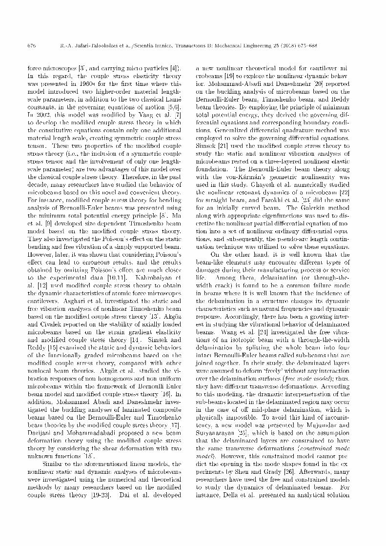
Figure 1. The schematic model of a delaminatedmicrobeam.
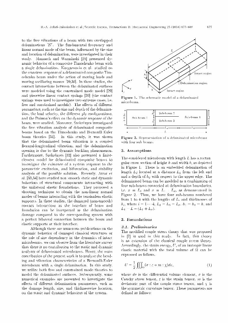
Figure 2. Representation of a delaminated microbeamwith four sub-beams.
2. Assumptions
The considered microbeam with length L has a rectan-gular cross-section of height h and width b, as depictedin Figure 1. There is an embedded delamination oflength Ld located at a distance L1 from the left endand a depth of h2 with respect to the upper edge. Thedelaminated beam can be modeled as a combination offour sub-beams connected at delamination boundaries,i.e. x = L1 and x = L1 + Ld, as demonstrated inFigure 2. Thus, we have four sub-beams numberedfrom 1 to 4 with the lengths of Li and thicknesses ofhi, where i = 1 � � � 4, L2 = L3 = Ld, h1 = h4 = h, andL4 = L� (L1 + Ld).
3. Formulations
3.1. PreliminariesThe modi�ed couple stress theory that was proposedin [7] is used in this study. In fact, this theoryis an extension of the classical couple stress theory.Accordingly, the strain energy, U , of an isotropic linearelastic material with the total volume of can beexpressed as follows:
U =12
y
(� : "+m : �)dv; (1)
where dv is the di�erential volume element, � is theCauchy stress tensor, " is the strain tensor, m is thedeviatoric part of the couple stress tensor, and � isthe symmetric curvature tensor. These parameters arede�ned as follows:
678 R.-A. Jafari-Talookolaei et al./Scientia Iranica, Transactions B: Mechanical Engineering 25 (2018) 675{688
" =12�ru+ (ru)T
�; (2)
� = �tr(")I + 2�"; (3)
� =12�r� + (r�)T � ; (4)
m = 2`2��; (5)
where � is the rotation vector de�ned by Eq. (6) asfollows:
� =12curl(u); (6)
where u is the displacement vector, ` is the materiallength scale, and � and � are the Lam�e's constants sothat they are related to both Young's modulus, E, andPoisson's ratio, v, as follows:
� =Ev
(1 + v)(1� 2v); (7)
� =E
2(1 + v): (8)
3.2. Governing equationsAccording to the Bernoulli-Euler beam theory, the dis-placement �eld for the ith sub-beam can be expressedas follows:
ui = �z (@wi(x; t)@x
; vi = 0;
wi = wi(x; t); i = 1; � � � ; 4; (9)
where ui, vi, and wi are the components of dis-placement vector in the directions of x, y, and z,respectively. By substituting Eq. (9) into Eq. (2), thestrain components of the ith sub-beam can be obtainedas follows:
"xxi = �z @2wi(x; t)@x2 ;
"yyi = "zzi = "xyi = "yzi = "zxi = 0: (10)
Furthermore, using Eqs. (3)-(8), one can obtain thestress components, rotation vector, symmetric curva-ture tensor, and deviatoric part of the couple stresstensor as follows:
�xxi = �(�+ 2�)z@2wi@x2 ;
�yyi = �zzi = ��z @2wi@x2 ;
�xyi = �yzi = �zxi = 0; (11)
�i =12
����������i J k
@@x
@@y
@@z
�z @wi@x 0 wi
���������� =�
0;�@wi@x
; 0�; (12)
�i =
������ 0 � 12@2wi@x2 0
� 12@2wi@x2 0 0
0 0 0
������ ; (13)
mi =
������ 0 �`2�@2wi@x2 0
�`2�@2wi@x2 0 0
0 0 0
������ : (14)
By substituting Eqs. (10)-(14) into Eq. (1), the expres-sion for strain energy of four sub-beams can be obtainedas follows:
U1 =12
L1Z0
((�+ 2�)I1
�@2w1
@x2
�2
+�`2A1
�@2w1
@x2
�2)dx; (15)
Ui =12
L1+LdZL1
((�+ 2�)Ii
�@2wi@x2
�2
+�`2Ai�@2wi@x2
�2)dx; i = 2; 3; (16)
U4 =12
LZL1+Ld
((�+ 2�)I4
�@2w4
@x2
�2
+�`2A4
�@2w4
@x2
�2)dx; (17)
where:
Ii =xAiz2dA; i = 1 � � � 4; (18)
and Ai is the cross-sectional area of the ith sub-beam.Furthermore, the kinetic energy of sub-beams can beexpressed as follows:
T1 =12
Z L1
0�A1
�@w1
@t
�2
dx; (19)
Ti =12
Z L1+Ld
L1
�Ai�@wi@t
�2
dx; i = 2; 3; (20)
T4 =12
Z L
L1+Ld�A4
�@w4
@t
�2
dx: (21)
Finally, the work done by external forces and momentscan be obtained as [8]:
W =x
(f:u+ c:�)dv +x@
(t:u+ s:�)da; (22)
where f , c, t, and s are the body force, body couple,surface traction, and surface couple, respectively, and@ is the surface of .
R.-A. Jafari-Talookolaei et al./Scientia Iranica, Transactions B: Mechanical Engineering 25 (2018) 675{688 679
3.2.1. Static analysisIn this section, the static bending analysis of thedelaminated microbeam is presented. The di�erentialequations for each sub-beam are derived using theprinciple of minimum total potential energy, which canbe expressed as [35]:
�� = �(U �W ) = 0; (23)
where � is the variational operator. Moreover, byde�nition, the total potential energy (�) is written asfollows:
� = U �W = U1 + U2 + U3 + U4 �W: (24)
The related equations according to both constrainedand free modes are presented in the following subsec-tions.
Constrained modeAccording to constrained mode model [25], sub-beamslocated in the delamination region have identical trans-verse displacement, i.e. w2 = w3. Using Eq. (23), thegoverning equations for the static bending of sub-beamsin this case are obtained as follows:
Did4wi(x)dx4 � qi(x) = 0; i = 1; 4; (25)
(D2 +D3)d4w2(x)dx4 � q2(x) = 0; (26)
where:Di = (�+ 2�)Ii + �`2Ai; i = 1� 4: (27)
In addition, qi (i = 1; 2, and 4) is the externalload applied to the ith sub-beams. The linear non-homogeneous di�erential Eqs. (25) and (26) can beintegrated to obtain the following solutions:
wi(x) =1Di
�x xqi(x)dxdxdxdx+
C1i
6x3
+C2i
2x2+C3ix+C4i
�; i=1 and 4;
(28)
w2(x) =1
D2 +D3
�x xq2(x)dxdxdxdx
+C12
6x3 +
C22
2x2 + C32x+ C42
�; (29)
where coe�cients Cji are unknown constants thatcan be determined by applying appropriate boundary,continuity, and compatibility conditions (details arepresented in Section 3.2.2). Note that Eqs. (28)and (29) represent the closed-form solution for thestatic de ection of the delaminated microbeam.
Free modeIn the free mode model, as mentioned before, sub-beams 2 and 3 were allowed to move freely without
touching each other. Thus, they have di�erent trans-verse displacements. By employing a similar processas used in the previous subsection, the governingequations of the sub-beams can be obtained as follows:
Did4wi(x)dx4 � qi(x) = 0; i = 1; � � � ; 4: (30)
By integrating Eq. (30), the static de ection of the de-laminated microbeam will be obtained by the followingformula:
wi(x) =1Di
�x xqi(x)dxdxdxdx+
C1i
6x3
+C2i
2x2 + C3ix+ C4i
�; i = 1; � � � ; 4:
(31)
3.2.2. Free vibration analysisIn this section, the free vibration analysis of delami-nated microbeam based on the Bernoulli-Euler beammodel is studied by employing the modi�ed couplestress theory. To this end, the di�erential equationsof motion for the problem in hand can be obtained byapplying the Hamilton's principle to the whole systemas follows [35]:
�Z t2
t1(T � U)dt = 0; (32)
where t1 and t2 are two arbitrary time instants. Substi-tuting Eqs. (15)-(17) and Eqs. (19)-(21) into Eq. (32)leads to the equations of motion that are presented inthe subsequent sections for the constrained and freemode models.
Constrained modeFor the constrained mode model, the governing di�er-ential equations of motion for the free vibration can bederived as follows:
Di@4wi@x4 + �Ai
@2wi@t2
= 0; i = 1; 4; (33)
(D2 +D3)@4w2
@x4 + �(A2 +A3)@2w2
@t2= 0: (34)
Using the separation of variables technique, the solu-tion to Eqs. (33) and (34) can be written as follows:
wi(x; t) = Wi(x) cos(!t); (i = 1; 2; 4); (35)
where ! and Wi(x) are the natural frequency andcorresponding mode shape of the ith sub-beam, respec-tively. Substituting Eq. (35) into Eqs. (33) and (34)and, subsequently, dividing both sides by cos(!t), weobtain the following fourth-order ordinary di�erentialequation:
d4Wi(x)dx4 � �4
iWi(x) = 0; i = 1; 4; (36a)
680 R.-A. Jafari-Talookolaei et al./Scientia Iranica, Transactions B: Mechanical Engineering 25 (2018) 675{688
d4W2(x)dx4 � �4
2W2(x) = 0; (36b)
where:
�4i =
�Ai!2
Di; i = 1; 4;
�42 =
�(A2 +A3)!2
D2 +D3:
We assume a solution to the form Wi(x) = Cesx.Substituting the assumed solution into the di�erentialequations (36a) and (36b), one can obtain s = ��,s = �i � (I is the complex variable). After somesimpli�cations, the appropriate solution for the modeshape can be obtained as follows:
Wi(x) =Ci cos(�ix) + Si sin(�ix) +Qi cosh(�ix)
+Ri sinh(�ix); i = 1; 2; 4: (37)
It is clear that, in this case, we have 12 unknowncoe�cients Ci, Si, Qi, and Ri (i = 1; 2, and 4).These coe�cients can be determined by 4 boundaryconditions as well as 8 continuity and compatibilityrelations. The appropriate boundary conditions thatcan be applied at the support ends (i.e., x = 0 and x =L) are Wi = 0 and W 0i = 0 for the clamped condition,Wi = 0 and W 00i = 0 for the simply supported type,W 00i = 0 and W 000i = 0 for the free end conditions wherei = 1 and 4. Note that, in the aforementioned relations,the prime sign denotes di�erentiation with respect tox-coordinate. The continuity conditions of de ectionand slope at two ends of the delamination zone arealso identi�ed as follows:
w1 = w2; w01 = w02; at x = L1; (38)
w4 = w2; w04 = w02; at x = L1 + Ld: (39)
Moreover, the compatibility conditions of shear forcecan be expressed:
D1w0001 = (D2 +D3)w0002 ; at x = L1; (40)
D4w0004 = (D2 +D3)w0002 ; at x = L1 + Ld: (41)
Finally, the compatibility conditions of bending mo-ments are obtained as follows:
D1W 001 =(D2+D3)W 002 � h21
4Ld
W 01(L1)�W 04(L1+Ld)
1(�+2�)A2
+ 1(�+2�)A3
!;
at x=L1; (42)
D4W 004 =(D2+D3)W 002 � h21
4Ld
W 01(L1)�W 04(L1+Ld)
1(�+2�)A2
+ 1(�+2�)A3
!;
at x=L1+Ld; (43)
where Eqs. (38)-(43) along with four boundary condi-tions provide 12 homogenous equations for 12 unknowncoe�cients Ci, Si, Qi, and Ri (i = 1, 2 and 4).Substituting Eq. (36) into these conditions leads tothe matrix-form equations [A]fC1; S1; � � � ; Q4; R4gT =f0g. To obtain a nontrivial solution to the unknowncoe�cients, the determinant of coe�cient matrix [A]must be zero, which forms the characteristic equationfor the system natural frequencies. In fact, theeigenvalues and eigenvectors of the above matrix-formequations are the natural frequencies and the corre-sponding mode shapes of the delaminated microbeam,respectively.
Free modeFor the free mode, the equations of motion are derivedas follows:
Di@4wi@x4 + �Ai
@2wi@t2
= 0; i = 1 � � � 4: (44)
The solution forms for the free mode model are iden-tical to the constrained mode. Note that there are16 unknown coe�cients that can be determined by 4boundary conditions and 12 continuity and compati-bility conditions. The boundary conditions for the freemode are identical to those that are presented for theconstrained mode. Moreover, the continuity conditionsfor de ection and slope and also compatibility condi-tions for the shear forces and bending moments are asfollows:
The continuity conditions of the transverse de ection:
w1 = w2; w1 = w3; at x = L1; (45)
w4 = w2; w4 = w3; at x = L1 + Ld: (46)
The continuity conditions of the slope:
w01 = w02; w01 = w03; at x = L1; (47)
w04 = w02; w04 = w03; at x = L1 + Ld: (48)
The compatibility conditions of the shear forces:
D1w0001 = D2w0002 +D3w0003 ; at x = L1; (49)
D4w0004 = D2w0002 +D3w0003 ; at x = L1 + Ld: (50)
The compatibility conditions of the bending moments:
D1W 001 = D2W 002 +D3W 003
� h21
4Ld
W 01(L1)�W 04(L1+Ld)
1(�+2�)A2
+ 1(�+2�)A3
!; at x=L1; (51)
D4W 004 = D2W 002 +D3W 003
� h21
4Ld
W 01(L1)�W 04(L1+Ld)
1(�+2�)A2
+ 1(�+2�)A3
!; at x=L1+Ld:
(52)
R.-A. Jafari-Talookolaei et al./Scientia Iranica, Transactions B: Mechanical Engineering 25 (2018) 675{688 681
Eqs. (45)-(52) and four appropriate boundary condi-tions make a set of 16 simultaneous linear homogenousalgebraic equations for 16 unknown coe�cients Ci,Si, Qi, and Ri(i = 1 � 4). The frequencies andcorresponding mode shapes can be obtained in a similarway that is described for the constrained mode model.
4. Numerical results
The beam model assumed here is taken to be made ofepoxy with E = 1:44 GPa, v = 0:38, � = 1220 kg/m3,and ` = 17:6 �m as elastic modulus, Poisson's ratio,density, and length-scale parameter, respectively [8].The veri�cations and results for the static case and freevibration case are presented in the next sections. Sinceincorporating the Poisson's ratio causes underestima-tion of de ection due to the overestimation of bendingrigidity of microbeam [10,11], the Poisson's ratio isassumed here to be zero. For all considered examples,unless mentioned otherwise, the beam's dimensionsare L = 20h1 and b = 2h1. Di�erent delaminationparameters vary, and their e�ects on the microbeambehavior are investigated.
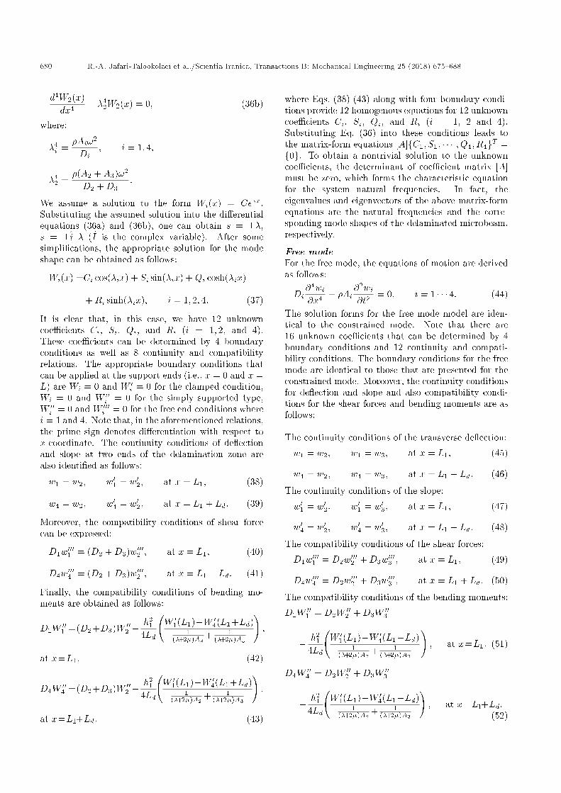
4.1. Static analysisAs shown in Figure 3, a cantilever beam with centraldelamination, which is subjected to a vertical forceat the free end, is considered here. The centraldelamination refers to a delamination whose centercoincides with the beam center. In order to verifythe present formulations, the delamination length isconsidered in�nitesimally small (i.e., Ld = 0:01L),and the constrained mode model is applied. For allnumerical examples in the static analysis, the loadmagnitude is taken to be P = 100 �N [8].
The de ection of the microbeam based on thepresent formulation is depicted in Figure 4. We can ob-serve that the de ection of the delaminated microbeamwith extremely small delamination length is identicalto the result reported previously by Park et al. [8] foran intact microbeam with the same conditions.
The e�ect of delamination length on the de ectionof the microbeam is investigated in Figure 5. Inthis case, the central delamination is placed on themid plane of the beam (i.e., h2 = h3). It is worth
Figure 3. The cantilever beam with the centraldelamination subjected to a point load P at its free end.
mentioning that, in this �gure and also in Figures 6-8, the blue lines in the left and right sides of thedelamination region refer to the de ection of sub-beams2 and 3, respectively. It is obvious that the beam'sde ection directly depends on the delamination lengthso that it increases when the delamination length
Figure 4. Static bending de ection for the cantilevermicrobeam subjected to a point load at its free end (seeFigure 3 with P = 100 �N). In order to verify our model,the delamination length is considered very small (i.e.,Ld = 0:01L) and the beam de ection is compared with thestatic deformation of intact microbeam obtained in [8].Note that SBi is abbreviated for ith sub-beam (i = 1; 4),and the delamination region is referred to sub-beams 2and 3.
Figure 5. E�ect of delamination length on the de ectionof cantilever micro beam (see Figure 3) with h2 = h3 andP = 100 �N. Note that the solid blue line refers to thede ection of the sub-beams 1 and 4, before and after thedelamination zone.
682 R.-A. Jafari-Talookolaei et al./Scientia Iranica, Transactions B: Mechanical Engineering 25 (2018) 675{688
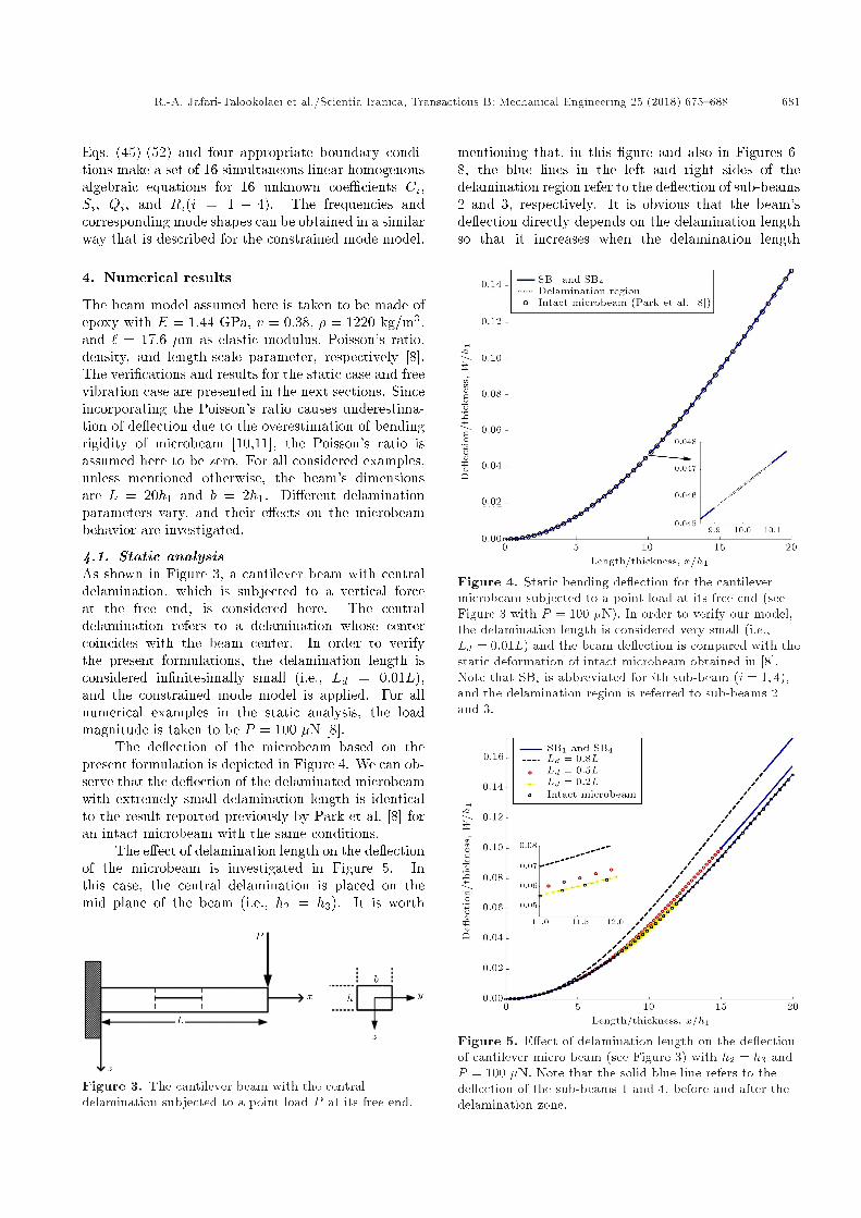
Figure 6. E�ect of delamination thicknesswise locationon the de ection of cantilever microbeam (see Figure 3)with Ld = 0:7L and P = 100 �N. Note that the solid blueline refers to the de ection of sub-beams 1 and 4, beforeand after the delamination zone.
Figure 7. E�ect of length-scale parameter on thede ection of cantilever microbeam (see Figure 3) withh2 = h3 = 0:5h1, Ld = 0:5L, P = 100 �N, h1 = 20 �m andn = h1=`. Note that the solid blue line refers to thede ection of the sub-beams 1 and 4, before and after thedelamination zone.
increases. This occurrence is because the delaminationdecreases the beam's overall sti�ness.
Figure 6 illustrates the e�ect of thicknesswiselocation of the delamination on the static de ectionof the delaminated microbeam. In this case, thelength of the central delamination is considered to beLd = 0:7L, and three di�erent thicknesswise locationsare considered. Therefore, it is observed that as the
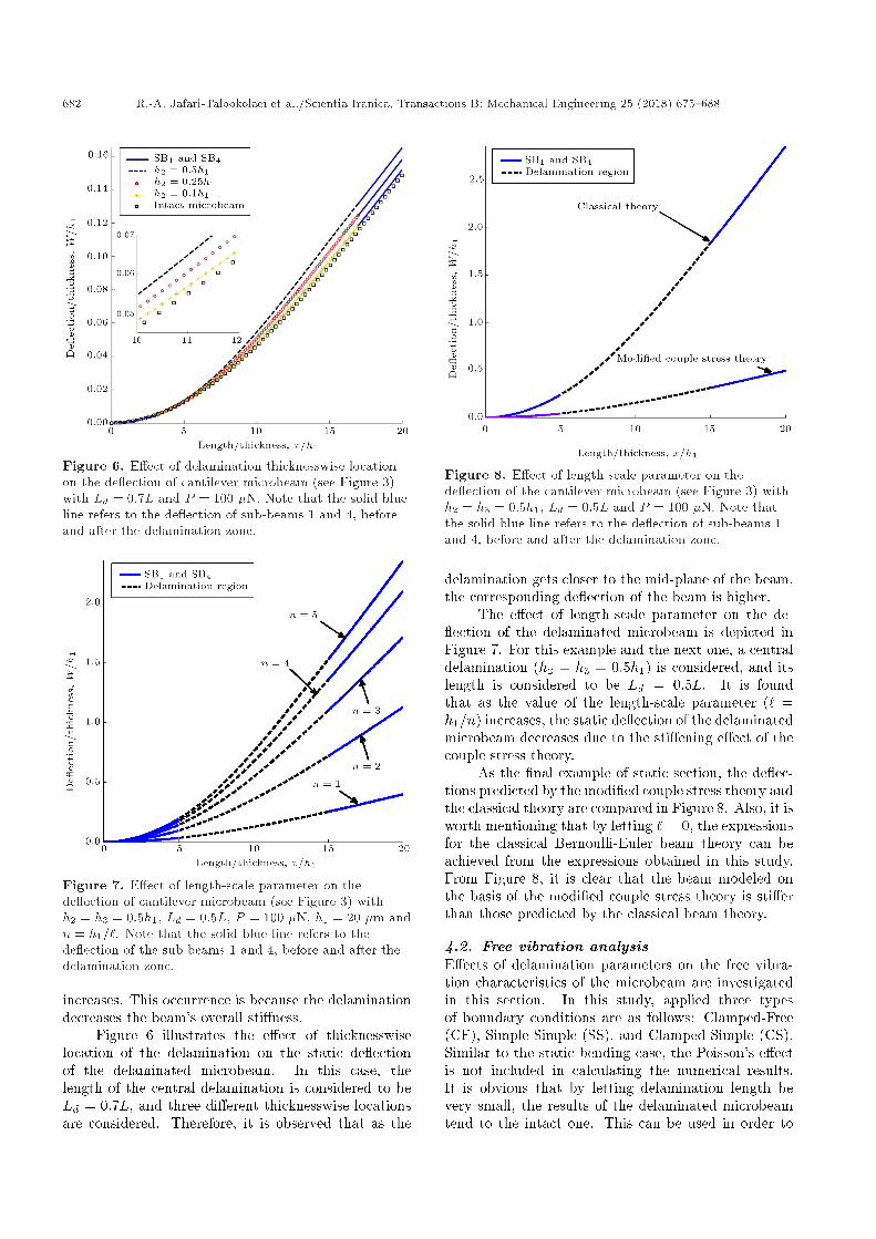
Figure 8. E�ect of length-scale parameter on thede ection of the cantilever microbeam (see Figure 3) withh2 = h3 = 0:5h1, Ld = 0:5L and P = 100 �N. Note thatthe solid blue line refers to the de ection of sub-beams 1and 4, before and after the delamination zone.
delamination gets closer to the mid-plane of the beam,the corresponding de ection of the beam is higher.
The e�ect of length-scale parameter on the de- ection of the delaminated microbeam is depicted inFigure 7. For this example and the next one, a centraldelamination (h2 = h3 = 0:5h1) is considered, and itslength is considered to be Ld = 0:5L. It is foundthat as the value of the length-scale parameter (` =h1=n) increases, the static de ection of the delaminatedmicrobeam decreases due to the sti�ening e�ect of thecouple stress theory.
As the �nal example of static section, the de ec-tions predicted by the modi�ed couple stress theory andthe classical theory are compared in Figure 8. Also, it isworth mentioning that by letting ` = 0, the expressionsfor the classical Bernoulli-Euler beam theory can beachieved from the expressions obtained in this study.From Figure 8, it is clear that the beam modeled onthe basis of the modi�ed couple stress theory is sti�erthan those predicted by the classical beam theory.
4.2. Free vibration analysisE�ects of delamination parameters on the free vibra-tion characteristics of the microbeam are investigatedin this section. In this study, applied three typesof boundary conditions are as follows: Clamped-Free(CF), Simple-Simple (SS), and Clamped-Simple (CS).Similar to the static bending case, the Poisson's e�ectis not included in calculating the numerical results.It is obvious that by letting delamination length bevery small, the results of the delaminated microbeamtend to the intact one. This can be used in order to
R.-A. Jafari-Talookolaei et al./Scientia Iranica, Transactions B: Mechanical Engineering 25 (2018) 675{688 683
Figure 9. Fundamental natural frequency of the simplysupported intact microbeam.
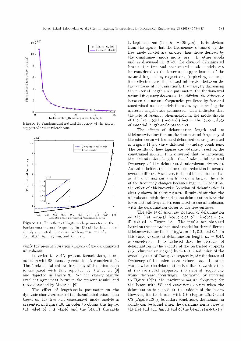
Figure 10. The e�ect of length-scale parameter on thefundamental natural frequency (in HZ) of the delaminatedsimply supported microbeam with h2 = h3 = 0:5h1,Ld = 0:5L, h1 = 20 �m, and L1 = L4.
verify the present vibration analysis of the delaminatedmicrobeam.
In order to verify present formulations, a mi-crobeam with SS boundary conditions is considered [9].The fundamental natural frequency of this microbeamis compared with that reported by Ma et al. [9]and depicted in Figure 9. We can clearly observeexcellent agreement between the present results andthose obtained by Ma et al. [9].
The e�ect of length-scale parameter on thedynamic characteristics of the delaminated microbeambased on the free and constrained mode models ispresented in Figure 10. In order to obtain this �gure,the value of ` is varied and the beam's thickness
is kept constant (i.e., h1 = 20 �m). It is obviousfrom the �gure that the frequencies obtained by thefree mode model are smaller than those derived bythe constrained mode model are. In other wordsand as discussed in [27-30] for classical delaminatedbeams, the free and constrained mode models canbe considered as the lower and upper bounds of thenatural frequencies, respectively (neglecting the non-liner e�ects due to the contact interaction between thetwo surfaces of delamination). Likewise, by decreasingthe material length-scale parameter, the fundamentalnatural frequency decreases. In addition, the di�erencebetween the natural frequencies predicted by free andconstrained mode models increases by decreasing thematerial length-scale parameter. This indicates thatthe role of opening phenomenon in the mode shapesof the free model is more distinct in the lower valuesof material length-scale parameter.
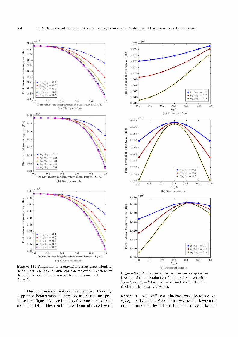
The e�ects of delamination length and itsthicknesswise location on the �rst natural frequency ofthe microbeam with central delamination are presentedin Figure 11 for three di�erent boundary conditions.The results of these �gures are obtained based on theconstrained model. It is observed that by increasingthe delamination length, the fundamental naturalfrequency of the delaminated microbeam decreases.As stated before, this is due to the reduction in beam'soverall sti�ness. Moreover, it should be mentioned thatas the delamination length becomes larger, the rateof the frequency changes becomes higher. In addition,the e�ect of thicknesswise location of delamination isclearly shown in these �gures. Results show that themicrobeams with the mid-plane delamination have thelower natural frequencies compared to the microbeamswith the delamination closer to the free surfaces.
The e�ects of spanwise location of delaminationon the �rst natural frequencies of microbeam areillustrated in Figure 12. The results are obtainedbased on the constrained mode model for three di�erentthicknesswise locations of h2=h1 = 0:1, 0.2, and 0.5. Inthis case, a constant delamination length Ld = 0:4Lis considered. It is deduced that the presence ofdelamination in the vicinity of the restricted supports(e.g., clamped or hinged) leads to the reduction of theoverall system sti�ness; consequently, the fundamentalfrequency of the microbeam reduces too. In otherwords, when the delamination is shifted towards eitherof the restricted supports, the natural frequencieswould decrease accordingly. Moreover, by referringto Figure 12(b), the maximum natural frequency forthe beam with SS end conditions occurs when thedelamination is placed at the middle of the beam.However, for the beams with CF (Figure 12(a)) andCS (Figure 12(c)) boundary conditions, the maximumpoints can be found when the delamination is close tothe free end and simple end of the beam, respectively.
684 R.-A. Jafari-Talookolaei et al./Scientia Iranica, Transactions B: Mechanical Engineering 25 (2018) 675{688
Figure 11. Fundamental frequencies versus dimensionlessdelamination length for di�erent thicknesswise locations ofdelamination in microbeams with h1 = 20 �m andL1 = L4.
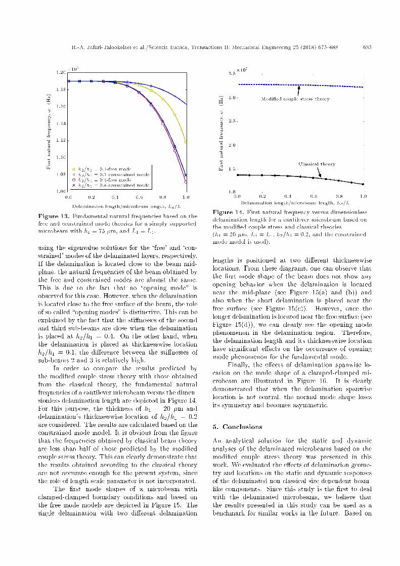
The fundamental natural frequencies of simplysupported beams with a central delamination are pre-sented in Figure 13 based on the free and constrainedmode models. The results have been obtained with
Figure 12. Fundamental frequencies versus spanwiselocation of the delamination for the microbeam withLd = 0:4L, h1 = 20 �m, L1 = L4 and three di�erentthicknesswise locations h2=h1.
respect to two di�erent thicknesswise locations ofh2=h1 = 0:1 and 0.4. We can observe that the lower andupper bounds of the natural frequencies are obtained
R.-A. Jafari-Talookolaei et al./Scientia Iranica, Transactions B: Mechanical Engineering 25 (2018) 675{688 685
Figure 13. Fundamental natural frequencies based on thefree and constrained mode theories for a simply supportedmicrobeam with h1 = 75 �m, and L1 = L4.
using the eigenvalue solutions for the `free' and `con-strained' modes of the delaminated layers, respectively.If the delamination is located close to the beam mid-plane, the natural frequencies of the beam obtained bythe free and constrained modes are almost the same.This is due to the fact that no \opening mode" isobserved for this case. However, when the delaminationis located close to the free surface of the beam, the roleof so-called \opening modes" is distinctive. This can beexplained by the fact that the sti�nesses of the secondand third sub-beams are close when the delaminationis placed at h2=h1 = 0:4. On the other hand, whenthe delamination is placed at thicknesswise locationh2=h1 = 0:1, the di�erence between the sti�nesses ofsub-beams 2 and 3 is relatively high.
In order to compare the results predicted bythe modi�ed couple stress theory with those obtainedfrom the classical theory, the fundamental naturalfrequencies of a cantilever microbeam versus the dimen-sionless delamination length are depicted in Figure 14.For this purpose, the thickness of h1 = 20 �m anddelamination's thicknesswise location of h2=h1 = 0:2are considered. The results are calculated based on theconstrained mode model. It is obvious from the �gurethat the frequencies obtained by classical beam theoryare less than half of those predicted by the modi�edcouple stress theory. This can clearly demonstrate thatthe results obtained according to the classical theoryare not accurate enough for the present system, sincethe role of length-scale parameter is not incorporated.
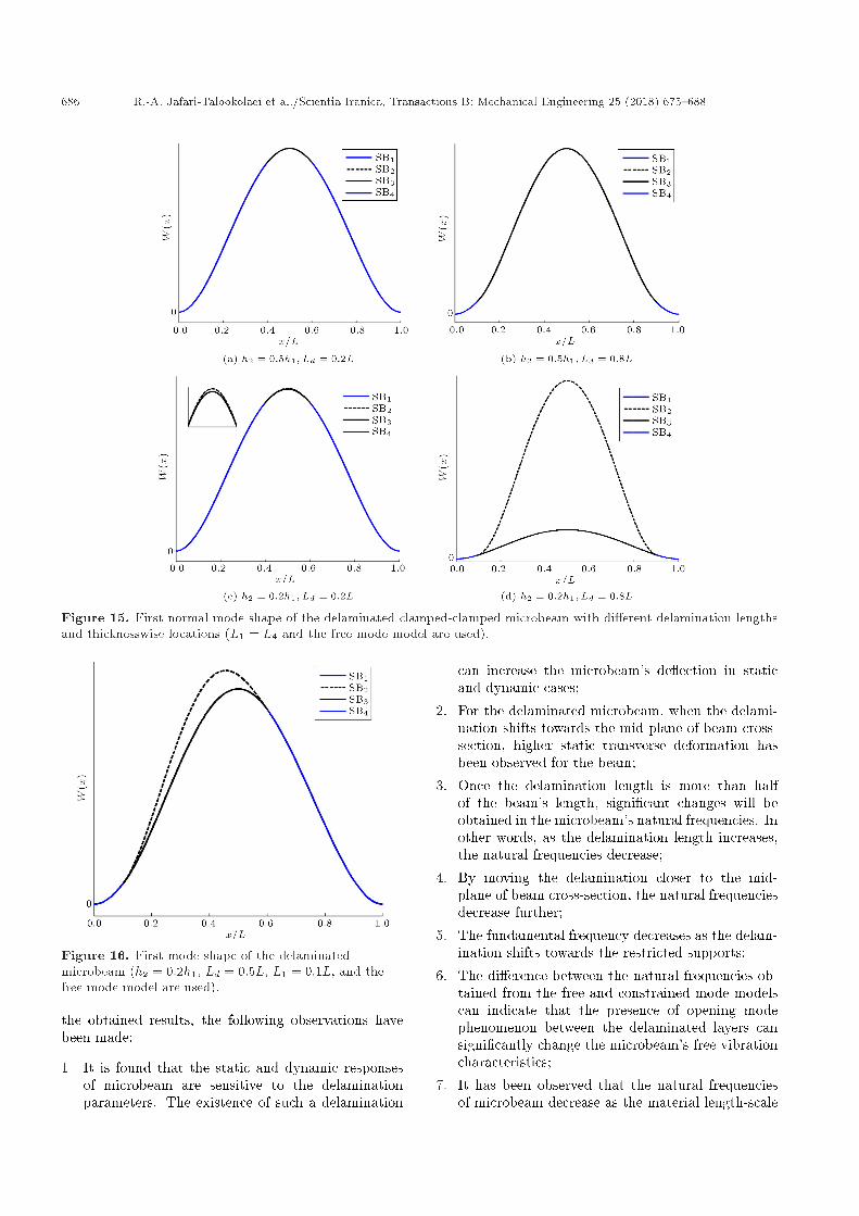
The �rst mode shapes of a microbeam withclamped-clamped boundary conditions and based onthe free mode models are depicted in Figure 15. Thesingle delamination with two di�erent delamination
Figure 14. First natural frequency versus dimensionlessdelamination length for a cantilever microbeam based onthe modi�ed couple stress and classical theories(h1 = 20 �m, L1 = L4, h2=h1 = 0:2, and the constrainedmode model is used).
lengths is positioned at two di�erent thicknesswiselocations. From these diagrams, one can observe thatthe �rst mode shape of the beam does not show anyopening behavior when the delamination is locatednear the mid-plane (see Figure 15(a) and (b)) andalso when the short delamination is placed near thefree surface (see Figure 15(c)). However, once thelonger delamination is located near the free surface (seeFigure 15(d)), we can clearly see the opening modephenomenon in the delamination region. Therefore,the delamination length and its thicknesswise locationhave signi�cant e�ects on the occurrence of openingmode phenomenon for the fundamental mode.
Finally, the e�ects of delamination spanwise lo-cation on the mode shape of a clamped-clamped mi-crobeam are illustrated in Figure 16. It is clearlydemonstrated that when the delamination spanwiselocation is not central, the normal mode shape losesits symmetry and becomes asymmetric.
5. Conclusions
An analytical solution for the static and dynamicanalyses of the delaminated microbeams based on themodi�ed couple stress theory was presented in thiswork. We evaluated the e�ects of delamination geome-try and locations on the static and dynamic responsesof the delaminated non-classical size-dependent beam-like components. Since this study is the �rst to dealwith the delaminated microbeams, we believe thatthe results presented in this study can be used as abenchmark for similar works in the future. Based on
686 R.-A. Jafari-Talookolaei et al./Scientia Iranica, Transactions B: Mechanical Engineering 25 (2018) 675{688
Figure 15. First normal mode shape of the delaminated clamped-clamped microbeam with di�erent delamination lengthsand thicknesswise locations (L1 = L4 and the free mode model are used).
Figure 16. First mode shape of the delaminatedmicrobeam (h2 = 0:2h1, Ld = 0:5L, L1 = 0:1L, and thefree mode model are used).
the obtained results, the following observations havebeen made:
1. It is found that the static and dynamic responsesof microbeam are sensitive to the delaminationparameters. The existence of such a delamination
can increase the microbeam's de ection in staticand dynamic cases;
2. For the delaminated microbeam, when the delami-nation shifts towards the mid-plane of beam cross-section, higher static transverse deformation hasbeen observed for the beam;
3. Once the delamination length is more than halfof the beam's length, signi�cant changes will beobtained in the microbeam's natural frequencies. Inother words, as the delamination length increases,the natural frequencies decrease;
4. By moving the delamination closer to the mid-plane of beam cross-section, the natural frequenciesdecrease further;
5. The fundamental frequency decreases as the delam-ination shifts towards the restricted supports;
6. The di�erence between the natural frequencies ob-tained from the free and constrained mode modelscan indicate that the presence of opening modephenomenon between the delaminated layers cansigni�cantly change the microbeam's free vibrationcharacteristics;
7. It has been observed that the natural frequenciesof microbeam decrease as the material length-scale
R.-A. Jafari-Talookolaei et al./Scientia Iranica, Transactions B: Mechanical Engineering 25 (2018) 675{688 687
parameter decreases. In addition, the di�erencebetween the frequencies obtained from the free andconstrained mode models increases when the valueof length-scale parameter decreases.
References
1. Hung, E.S. and Senturia, S.D. \Extending the travelrange of analog-tuned electrostatic actuators", J. Mi-croelectromech. S., 8(4), pp. 497-505 (1999).
2. Pei, J., Tian, F., and Thundat, T. \Novel glucosebiosensor based on the microcantilever", Anal. Chem.,76, pp. 292-297 (2004).
3. Pereira, R.D.S. \Atomic force microscopy as a novelpharmacological tool", Biochem. Pharmacol., 62, pp.975-983 (2001).
4. Jafari-Talookolaei, R.A., Abedi, M., S�im�sek, M., andAttar, M. \Dynamics of a micro scale Timoshenkobeam subjected to a moving micro particle based onthe modi�ed couple stress theory", J. Vib. Control,24(3), pp. 527-548 (2018).
5. Mindlin, R. and Tiersten, H. \E�ects of couple-stressesin linear elasticity", Arch. Ration. Mech. An., 11, pp.415-448 (1962).
6. Toupin, R.A. \Elastic materials with couple-stresses",Arch. Ration. Mech. An., 11, pp. 385-414 (1962).
7. Yang, F., Chong, A., Lam, D., and Tong, P. \Couplestress based strain gradient theory for elasticity", Int.J. Solids Struct., 39, pp. 2731-2743 (2002).
8. Park, S.K. and Gao, X.L. \Bernoulli-Euler beammodel based on a modi�ed couple stress theory", J.Micromech. Microeng., 16, pp. 2355-2359 (2006).
9. Ma, H.M., Gao, X.L., and Reddy, J. \A micro-structure-dependent Timoshenko beam model basedon a modi�ed couple stress theory", J. Mech. Phys.Solids, 56, pp. 3379-3391 (2008).
10. Dehrouyeh-Semnani, A.M. and Nikkhah-Bahrami, M.\A discussion on incorporating the Poisson e�ect inmicro-beam models based on modi�ed couple stresstheory", Int. J. Eng. Sci., 86, pp. 20-25 (2015).
11. Reddy, J.N. and El-Borgi, S. \Eringen's nonlocaltheories of beams accounting for moderate rotations",Int. J. Eng. Sci., 82, pp. 159-177 (2014).
12. Kahrobaiyan, M.H., Asghari, M., Rahaeifard, M., andAhmadian, M.T. \Investigation of the size-dependentdynamic characteristics of atomic force microscopemicrocantilevers based on the modi�ed couple stresstheory", Int. J. Eng. Sci., 48, pp. 1985-1994 (2010).
13. Asghari, M., Kahrobaiyan, M.H., and Ahmadian, M.T.\A nonlinear Timoshenko beam formulation based onthe modi�ed couple stress theory", Int. J. Eng. Sci.,48, pp. 1749-1761 (2010).
14. Akg�oz, B. and Civalek, �O. \Strain gradient elasticityand modi�ed couple stress models for buckling analysisof axially loaded micro-scaled beams", Int. J. Eng.Sci., 49, pp. 1268-1280 (2011).
15. Simsek, M. and Reddy, J.N. \Bending and vibration offunctionally graded micro-beams using a new higherorder beam theory and the modi�ed couple stresstheory", Int. J. Eng. Sci., 64, pp. 37-53 (2013).
16. Akg�oz, B. and Civalek, �O. \Free vibration analysisof axially functionally graded tapered Bernoulli-Eulermicro-beams based on the modi�ed couple stress the-ory", Compos. Struct., 98, pp. 314-322 (2013).
17. Mohammad Abadi, M. and Daneshmehr, A.R. \An in-vestigation of modi�ed couple stress theory in bucklinganalysis of micro composite laminated Euler-Bernoulliand Timoshenko beams", Int. J. Eng. Sci., 75, pp.40-53 (2014).
18. Darijani, H. and Mohammadabadi, H. \A new defor-mation beam theory for static and dynamic analysis ofmicro-beams", Int. J. Mech. Sci., 89, pp. 31-39 (2014).
19. Dai, H.L., Wang, Y.K., and Wang, L. \Nonlinear dy-namics of cantilevered micro-beams based on modi�edcouple stress theory", Int. J. Eng. Sci., 94, pp. 103-112(2015).
20. Mohammad-Abadi, M. and Daneshmehr, A.R. \Sizedependent buckling analysis of micro-beams based onmodi�ed couple stress theory with high order theoriesand general boundary conditions", Int. J. Eng. Sci.,74, pp. 1-14 (2014).
21. Simsek, M. \Nonlinear static and free vibration anal-ysis of micro-beams based on the nonlinear elasticfoundation using modi�ed couple stress theory andHe's variational method", Compos. Struct., 112, pp.264-272 (2014).
22. Ghayesh, M.H., Farokhi, H., and Amabili, M. \Non-linear dynamics of a microscale beam based on themodi�ed couple stress theory", Compos. Eng., 50, pp.318-324 (2013).
23. Farokhi, H., Ghayesh, M.H., and Amabili, M. \Nonlin-ear dynamics of a geometrically imperfect micro-beambased on the modi�ed couple stress theory", Int. J.Eng. Sci., 68, pp. 11-23 (2013).
24. Wang, J.T.S., Liu, Y.Y., and Gibby, J.A. \Vibrationsof split beams", J. Sound Vib., 84, pp. 491-502 (1982).
25. Mujumdar, P.M. and Suryanarayan, S. \Flexural vi-brations of beams with delaminations", J. Sound Vib.,125, pp. 441-461 (1988).
26. Shen, M.H. and Grady, J.E. \Free vibrations of delam-inated beams", AIAA J., 30, pp. 1361-1370 (1992).
27. Della, C.N., Shu, D., and MSRao, P. \Vibrations ofbeams with two overlapping delaminations", Compos.Struct., 66, pp. 101-108 (2004).
28. Manoach, E., Warminski Mitura, J.A., and Samborski,S. \Dynamics of a composite Timoshenko beam withdelamination", Mech. Res. Commun., 46, pp. 47-53(2012).
29. Kargarnovin, M.H., Ahmadian, M.T., and Jafari-Talookolaei, R.A. \Forced vibration of delaminatedTimoshenko beams subjected to a moving load", Sci.Eng. Compos. Mater., 19, pp. 145-157 (2012).
688 R.-A. Jafari-Talookolaei et al./Scientia Iranica, Transactions B: Mechanical Engineering 25 (2018) 675{688
30. Kargarnovin, M.H., Jafari-Talookolaei, R.A., and Ah-madian, M.T. \Vibration analysis of delaminatedTimoshenko beams under the motion of a constantamplitude point force traveling with uniform velocity",Int. J. Mech. Sci., 70, pp. 39-49 (2013).
31. Szekr�enyes, A. \Coupled exural-longitudinal vibra-tion of delaminated composite beams with local sta-bility analysis", J. Sound Vib., 333, pp. 5141-5164(2014).
32. Szekrenyes, A. \A special case of parametrically ex-cited systems: Free vibration of delaminated compos-ite beams", Eur. J. Mech. A-Solid, 49, pp. 82-105(2015).
33. Attar, M., Karrech, A., and Regenauer-Lieb, K. \Non-linear modal analysis of structural components sub-jected to unilateral constraints", J. Sound Vib., 389,pp. 380-410 (2016).
34. Attar, M., Karrech, A., and Regenauer-Lieb, K. \Non-linear analysis of beam-like structures on unilateralfoundations: a lattice spring model", Int. J. SolidsStruct., 88, pp. 192-214 (2016).
35. Clive, L.D. and Shames, I.H., Solid Mechanics, AVariational Approach, Springer (2013).
Biographies
Ramazan-Ali Jafari-Talookolaei is currently anAssistant Professor at the School of Mechanical En-gineering, Babol Noshirvani University of Technology.He obtained his BSc in Mechanical Engineering fromShahrood University of Technology in 2002, his MScand PhD degrees in Mechanical Engineering fromSharif University of Technology in 2004 and 2013, re-spectively. His current research interests include lami-nated composite structures, micro and nano structures,�nite-element method, analytical solutions, dynamics,
vibration, linear and non-linear analyses, and damagedstructures. He has published 3 books and more than60 journal and conference papers.
Nima Ebrahimzade is currently a PhD candidateof Mechanical Engineering at the School of Mechan-ical and Systems Engineering, Newcastle University-UK. He received his MSc in Mechanical Engineeringfrom Babol Noshirvani University of Technology-Iranin 2016. His Research interests include nonlineardynamics and vibration, aeroelasticity, and MEMS.
Saeed Rashidi-Juybari received his MSc degreein Mechanical Engineering from the Department ofMechanical engineering at Babol Noshirvani Universityof Technology, Iran in 2016 and his BSc degree fromthe University of Tafresh, Iran. His research inter-ests are uid-structure interaction, o�shore and oceanengineering, wave energy conversion, and structuralvibration.
Khashayar Teimoori is a PhD candidate of Mechan-ical Engineering and Adjunct Lecturer in the GroveSchool of Engineering at the City College of the CityUniversity of New York, where he obtained his MScdegree in Mechanical Engineering. He completed hisBSc in Mechanical Engineering at Tehran Scienceand Research Branch of the Islamic Azad Universityunder the supervision of late distinguished ProfessorMohammad H. Kargarnovin. His research interestsinclude both pure and applied scienti�c topics in Me-chanical Engineering and Mathematical Sciences suchas; mechanical vibration, applied mechanics in uid-structure/solid interactions, electro-mechanobiologicalsystems, however, the interests are not limited to thementioned topics.