Embed Size (px)
Citation preview

BestReach Rigid Belt
ModelsBRB 230 OSBRB 230 SSBRB 460 OSBRB 460 SS
Best Diversified Products Inc.107 Flint Street
Jonesboro, AR 72401Phone 870-935-0970
Toll Free: 800-327-9209Fax: 870-935-3661
Best Diversified Products, Inc.
TM
Product Manual
Please read entire manual before operating conveyor
99039May, 2001
1
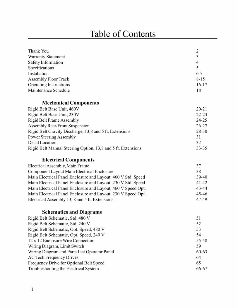
Table of Contents
Thank You 2Warranty Statement 3Safety Information 4Specifications 5Installation 6-7Assembly Floor Track 8-15Operating Instructions 16-17Maintenance Schedule 18
Mechanical ComponentsRigid Belt Base Unit, 460V 20-21Rigid Belt Base Unit, 230V 22-23Rigid Belt Frame Assembly 24-25Assembly Rear/Front Suspension 26-27Rigid Belt Gravity Discharge, 13,8 and 5 ft. Extensions 28-30Power Steering Assembly 31Decal Location 32Rigid Belt Manual Steering Option, 13,8 and 5 ft. Extensions 33-35
Electrical ComponentsElectrical Assembly, Main Frame 37Component Layout Main Electrical Enclosure 38Main Electrical Panel Enclosure and Layout, 460 V Std. Speed 39-40Main Electrical Panel Enclosure and Layout, 230 V Std. Speed 41-42Main Electrical Panel Enclosure and Layout, 460 V Speed Opt. 43-44Main Electrical Panel Enclosure and Layout, 230 V Speed Opt. 45-46Electrical Assembly 13, 8 and 5 ft. Extensions 47-49
Schematics and DiagramsRigid Belt Schematic, Std. 480 V 51Rigid Belt Schematic, Std. 240 V 52Rigid Belt Schematic, Opt. Speed, 480 V 53Rigid Belt Schematic, Opt. Speed, 240 V 5412 x 12 Enclosure Wire Connection 55-58Wiring Diagram, Limit Switch 59Wiring Diagram and Parts List Operator Panel 60-63AC Tech Frequency Drives 64Frequency Drive for Optional Belt Speed 65Troubleshooting the Electrical System 66-67

2
THANK YOU
Thank you for purchasing our BESTREACH conveyor. We realize you had a choice and it excites usthat you selected a conveyor from BEST Diversified Products, Inc.
We are providing you with a toll-free number, 800-845-3783, to put you directly in touch with ourCustomer Service Department. Call us for any reason. We realize it’s not our opinion of our productsand service that counts—it’s your opinion we live by!
We are in business to serve our customers. From the factory or the field, we are eager to help. OurSales/Service technicians have the experience and expertise to ensure a smooth transition between yourfixed conveyors and your BEST system. You will receive the same high level service from BEST beforeand after the sale.
Again, we appreciate your purchase and hope you will continue to select the BEST solution for yourmaterial handling needs.
Sincerely,
The Associates of BEST Diversified Products, Inc.Jonesboro, Arkansas

3
Your Best conveyor is protected by our premier warranty. Best Diversified Products, Inc. will replace, free ofcharge, parts that are damaged during the course of normal operation due to material or workmanship defects.This warranty extends for a period of two (2) years on all mechanical components and one (1) year on allelectrical components, as measured from the date you take possession of your conveyor.
This warranty does not cover damage due to accident, misuse, abuse, and negligence. This warranty does notcover damage due to improper operation or maintenance, connection to improper voltage supply, or at-tempted repair/modification by anyone other than an authorized Best Diversified Products, Inc. service per-sonnel.
For specific warranty information or assistance, please contact your Best Diversified Products, Inc. salesrepresentative at 1-800-327-9209.
WARRANTY STATEMENT
4
s Avoid wearing excessively loose clothing or hanging jewelry when workingwith moving machinery.
s Keep long hair pulled up to prevent it from becoming caught in moving parts.
s Remove any obstructions from the path of the conveyor.
s Make sure others move away from the conveyor before moving the unit orstarting the conveyor bed.
s Best Diversified Products, Inc. conveyors and their electrical systems mustonly be serviced by properly trained and qualified technicians.
s Never service the conveyor with power applied. Always disconnect powerbefore servicing equipment.
s Never operate conveyor with any electrical enclosure open.
s Never operate conveyor with any guards removed.
SAFETY INFORMATION
5
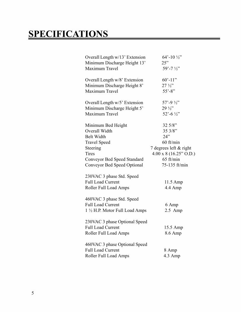
Overall Length w/13’ Extension 64’-10 ½”Minimum Discharge Height 13’ 25”Maximum Travel 59’-7 ½”
Overall Length w/8’ Extension 60’-11”Minimum Discharge Height 8’ 27 ½”Maximum Travel 55’-8”
Overall Length w/5’ Extension 57’-9 ½”Minimum Discharge Height 5’ 29 ½”Maximum Travel 52’-6 ½”
Minimum Bed Height 32 5/8”Overall Width 35 3/8”Belt Width 24”Travel Speed 60 ft/minSteering 7 degrees left & rightTires 4.00 x 8 (16.25” O.D.)Conveyor Bed Speed Standard 65 ft/minConveyor Bed Speed Optional 75-135 ft/min
230VAC 3 phase Std. SpeedFull Load Current 11.5 AmpRoller Full Load Amps 4.4 Amp
460VAC 3 phase Std. SpeedFull Load Current 6 Amp1 ½ H.P. Motor Full Load Amps 2.5 Amp
230VAC 3 phase Optional SpeedFull Load Current 15.5 AmpRoller Full Load Amps 8.6 Amp
460VAC 3 phase Optional SpeedFull Load Current 8 AmpRoller Full Load Amps 4.3 Amp
SPECIFICATIONS
6
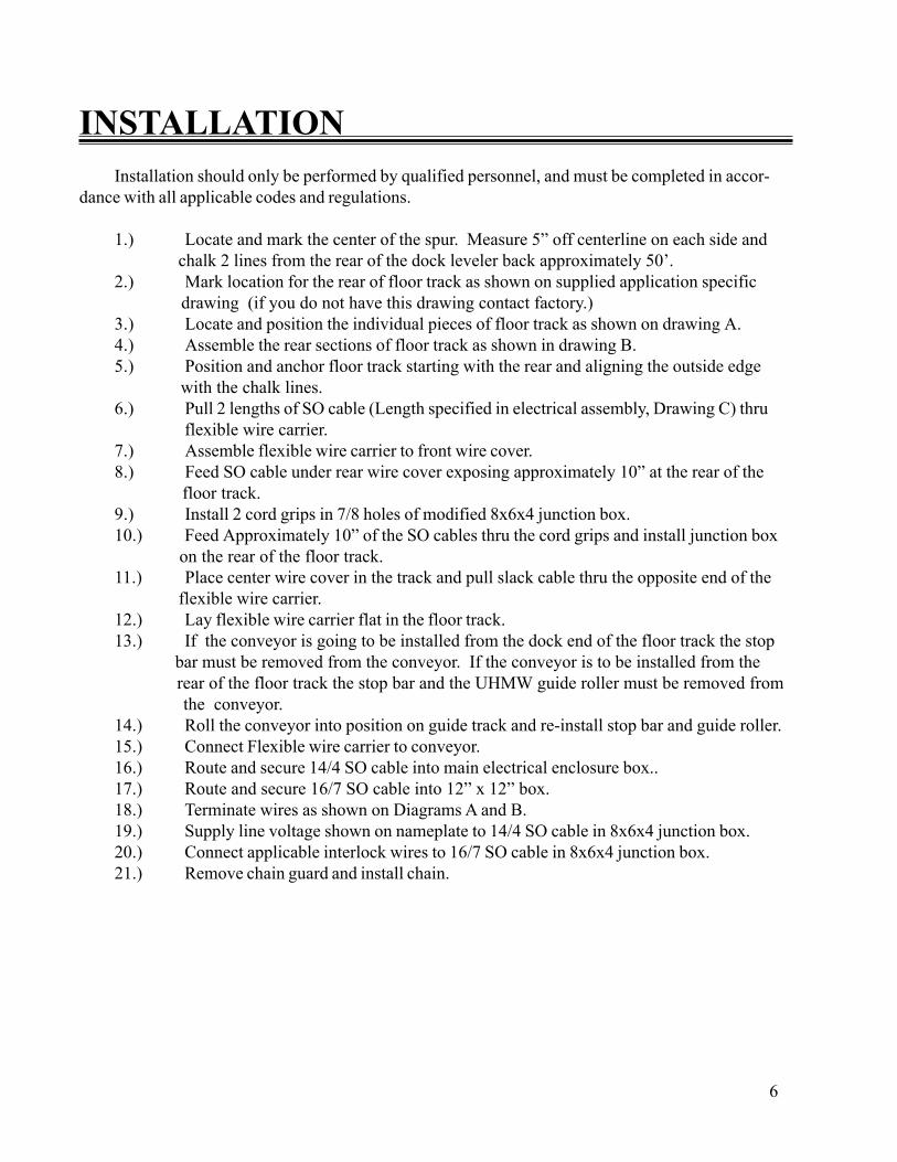
INSTALLATIONInstallation should only be performed by qualified personnel, and must be completed in accor-
dance with all applicable codes and regulations.
1.) Locate and mark the center of the spur. Measure 5” off centerline on each side and chalk 2 lines from the rear of the dock leveler back approximately 50’.
2.) Mark location for the rear of floor track as shown on supplied application specific drawing (if you do not have this drawing contact factory.)
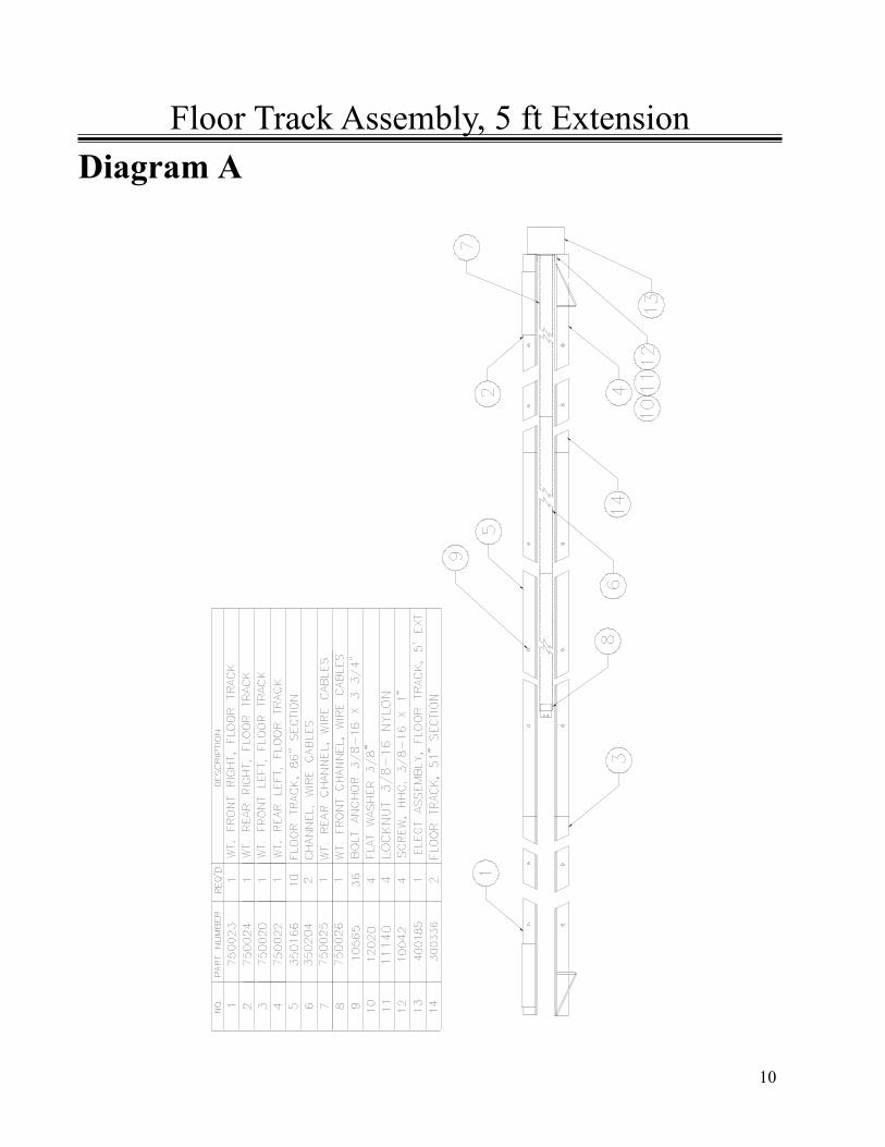
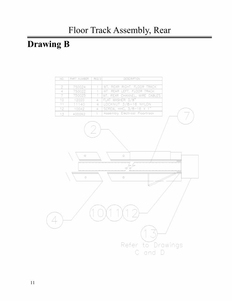
3.) Locate and position the individual pieces of floor track as shown on drawing A.4.) Assemble the rear sections of floor track as shown in drawing B.5.) Position and anchor floor track starting with the rear and aligning the outside edge
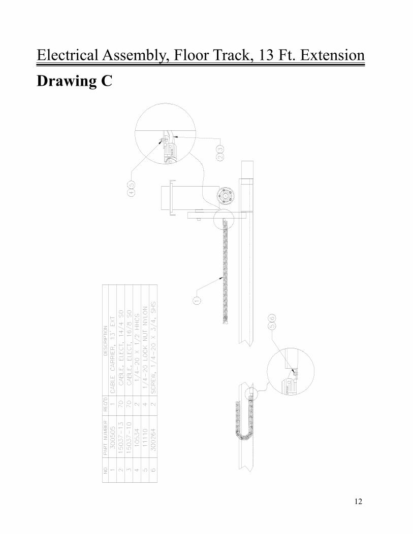
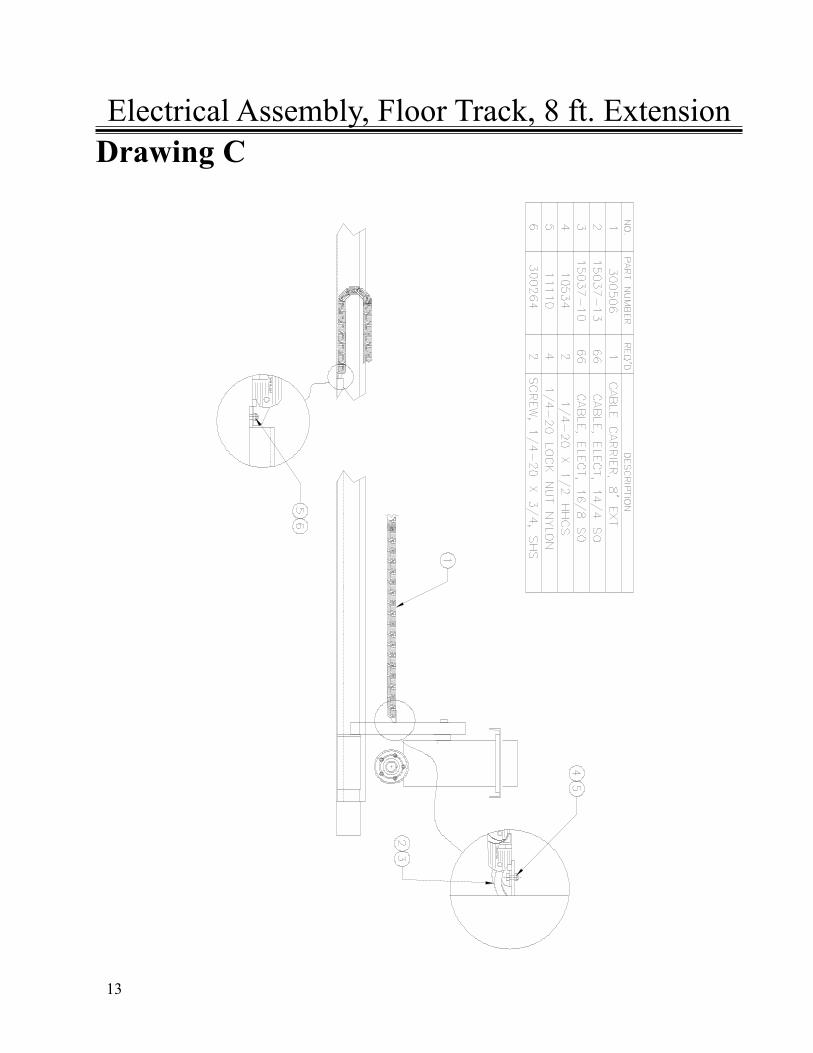
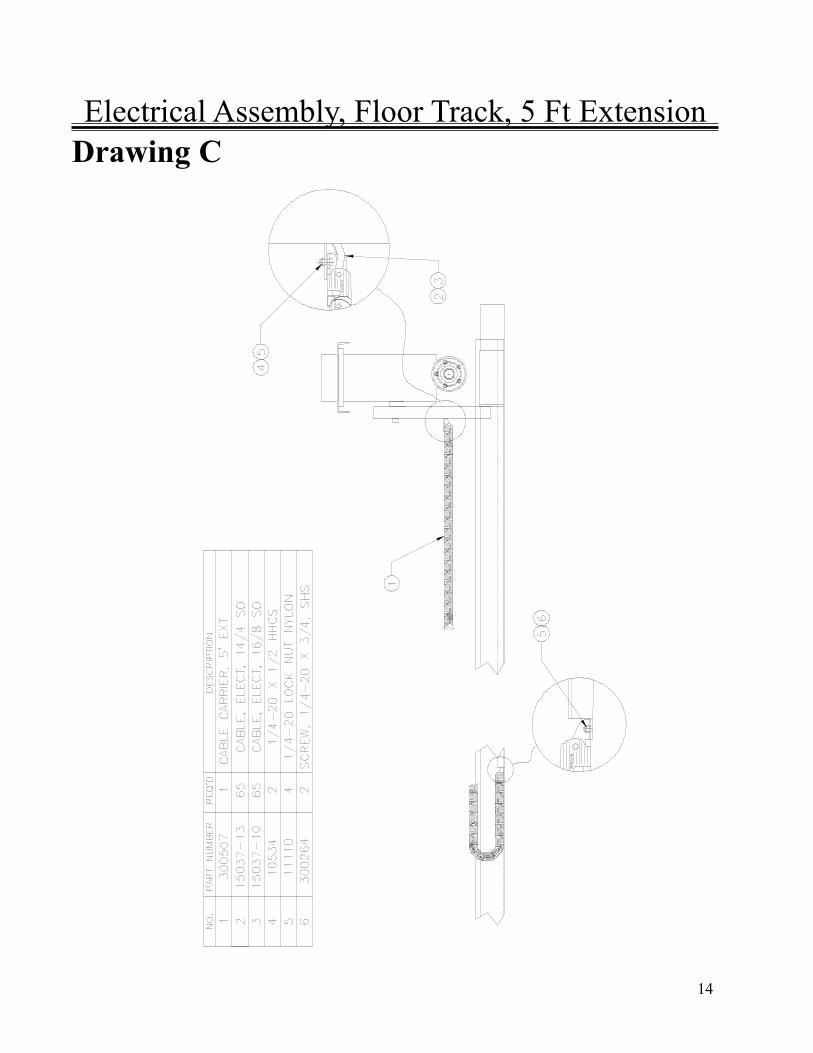
with the chalk lines.6.) Pull 2 lengths of SO cable (Length specified in electrical assembly, Drawing C) thru
flexible wire carrier.7.) Assemble flexible wire carrier to front wire cover.8.) Feed SO cable under rear wire cover exposing approximately 10” at the rear of the
floor track.9.) Install 2 cord grips in 7/8 holes of modified 8x6x4 junction box.10.) Feed Approximately 10” of the SO cables thru the cord grips and install junction box
on the rear of the floor track.11.) Place center wire cover in the track and pull slack cable thru the opposite end of the
flexible wire carrier.12.) Lay flexible wire carrier flat in the floor track.13.) If the conveyor is going to be installed from the dock end of the floor track the stop
bar must be removed from the conveyor. If the conveyor is to be installed from the rear of the floor track the stop bar and the UHMW guide roller must be removed from the conveyor.
14.) Roll the conveyor into position on guide track and re-install stop bar and guide roller.15.) Connect Flexible wire carrier to conveyor.16.) Route and secure 14/4 SO cable into main electrical enclosure box..17.) Route and secure 16/7 SO cable into 12” x 12” box.18.) Terminate wires as shown on Diagrams A and B.19.) Supply line voltage shown on nameplate to 14/4 SO cable in 8x6x4 junction box.20.) Connect applicable interlock wires to 16/7 SO cable in 8x6x4 junction box.21.) Remove chain guard and install chain.
7
BELT INSTALATION AND TRACKING:
Unroll the belt, PVC coating side up, around the tail pulley and over the idler rollers. Run beltover the snub roller and around the drive roll. Align the seam near the center of the conveyor frame.Pull the belt together to engage the lacing and install the pin. There are two permanent marks in thecenter of the belt width approximately 20 feet back from the lacing and 10 feet apart. Find thesemarks and take an exact measurement between them. Add .375” (3/8”) to the measurement. Ex-ample (measured 119 9/16” + 3/8” = 119 15/16). For proper tension, adjust the tail pulley so thedistance between the two marks is equal to the sum of the measured dimension and 3/8”. To insurethe tail pulley is square, be sure both tail pulley blocks are equal distance from the rear of the con-veyor frame. After tracking the belt, check the dimension between the marks to make sure propertension is still in the belt. If the dimension has changed, adjust accordingly and recheck for propertracking.
INSTALLATION (cont)
With the belt installed, begin the tracking procedure. The drive roll should be parallel to thesnub roller. The snub roller should be locked into place. All idler rollers are square to the frame.Start the belt. Watch to see which side the belt wants to run to and also how quickly it does so. Shutoff the conveyor. Begin belt tracking by adjusting the first idler from the tail. Loosen the bolts on theidler bracket and angle the roller to correct the belt travel. The roller will steer the belt toward theuphill side of the roller (Uphill refers to the belt travel direction). If further correction is necessary,proceed to adjust the first idler from the front, then the two in the center of the conveyor, in thatorder. If adjusting the idlers cannot solve the tracking problem, the tail pulley may have to be ad-justed slightly.
Adjusting the idler rollers will solve most all of the belt tracking problems. The belt shouldrun straight and on the center of the slider bed. Practice and experience will speed up the belt track-ing process.
8
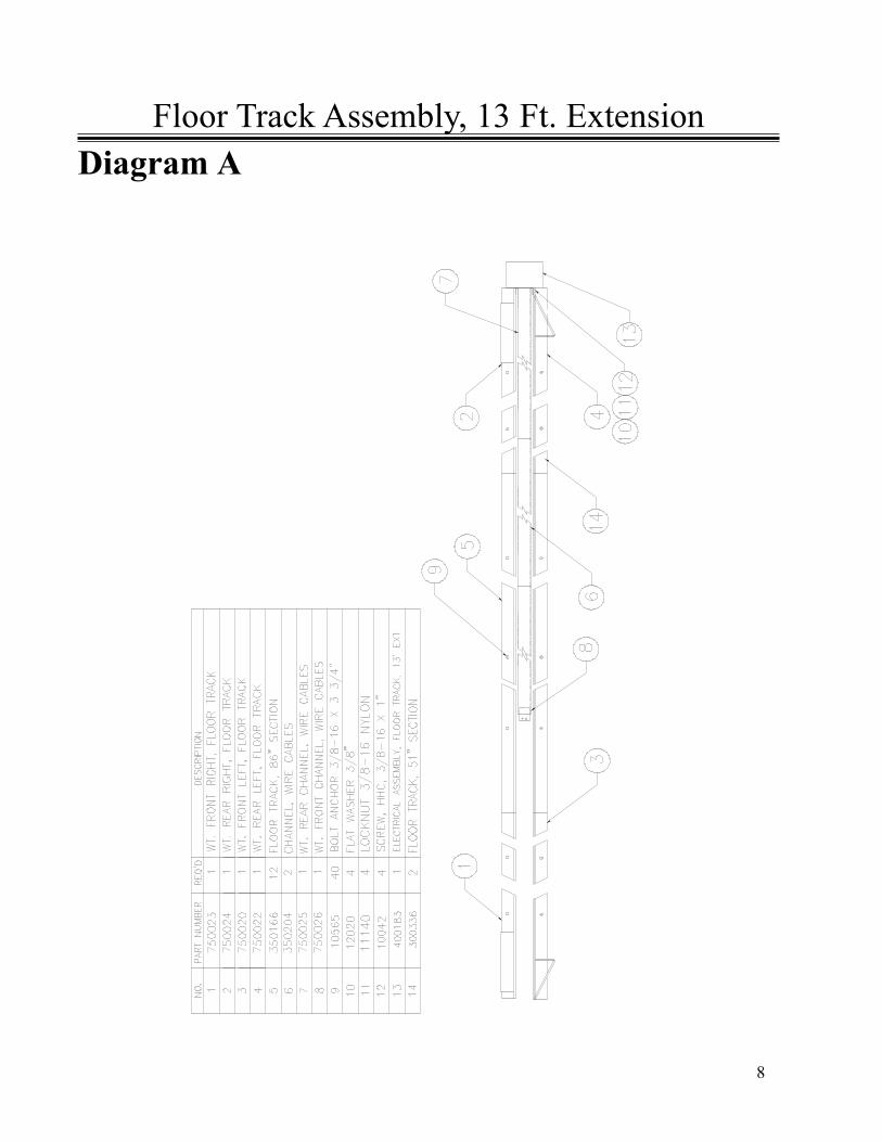
Floor Track Assembly, 13 Ft. ExtensionDiagram A
9
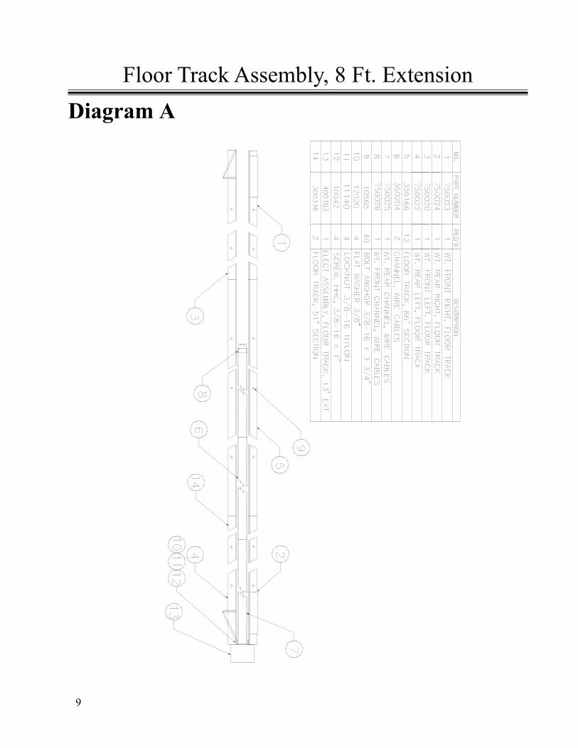
Floor Track Assembly, 8 Ft. ExtensionDiagram A
10
Floor Track Assembly, 5 ft ExtensionDiagram A
11
Drawing BFloor Track Assembly, Rear
12
Electrical Assembly, Floor Track, 13 Ft. ExtensionDrawing C
13
Electrical Assembly, Floor Track, 8 ft. ExtensionDrawing C
14
Electrical Assembly, Floor Track, 5 Ft ExtensionDrawing C
15
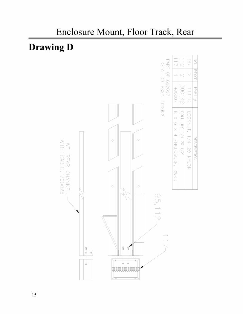
Drawing DEnclosure Mount, Floor Track, Rear
16
An emergency stop circuit controls electrical power to all parts of the conveyor. When any oneemergency stop switch is activated, power is removed from all motors and actuators stopping allmovement of the conveyor frame and bed. All electrical power is also removed from the motors andactuators when the DOOR DISCONNECT HANDLE is in the OFF or OPEN positions.
A. With interlocking door disconnect in the ON position and all Emergency Stop buttons out andoptional Cable Pull switches in the run position, the operator pushes either RESET button. TheMASTER CONTACTOR is energized and the machine is ready to respond to the operator’sinputs.
B. Moving the joystick in the DOWN direction starts the traversing motor in the forward directionafter the beeper is sounded for approximately 1.5 seconds , moving the unit toward the dockdoor. Releasing the joystick will return it to its centered position, stopping the motor. Movingthe joystick UP starts the traversing motor in the opposite direction after the beeper is sounded.
C. The LEFT and RIGHT positions of the joystick cause the steering actuator to steer the unit. Theunit will steer in the same direction as the joystick movement when the unit is moving forward.
D. The conveyor bed is controlled by the OFF ON pushbutton. Pressing it once will start the bedafter the beeper is sounded continuously for approximately 1 second. When the bed is running,pressing this pushbutton turns off the bed.
E. At any time either Emergency Stop switch may be pushed to de-energize the MASTER contactor. Thiswill remove power from all motors and actuators. To restart the machine, the Emergency Stop that wasactivated must be reset and either RESET pushbutton momentarily depressed. Any motor that wasrunning prior to the Emergency Stop will have to be restarted through the Operator’s Control Panel.
F. A feeder control switch provides dry contacts for a customer connection to control the feeder forthe spur or any other function the customer requires.
OPERATING INSTRUCTIONS
PROGRAMMING PACKAGE STOP PHOTOEYES:• Switch on 12” x 12” enclosure on the extension should be in the down position for normal
operation.• To program, flip switch to up position. Cover photoeye for the desired shut off delay time required on the conveyor belt. There should be a continuous beep for
the time the photoeye is covered during programming.
17
• Return switch to the down position for operation.• To return to default settings of 3 seconds delay, flip switch up and down three times in 2 sec.
The default settings will be reinstated and the switch is in down position for operation.
INDEXING OPTION AND PHOTOEYE PROGRAMMING:• This conveyor can be equipped with an electronic package indexing option.• The indexing option is switched on and off using a selector switch on the operator control
panel. In the on position, the conveyor is in normal operating mode. When the switch is off, theconveyor will index packages a programmable distance after they pass through the indexingphotoeye located on the transition.
• Programming this distance follows the same procedure as the package stop photoeyeexcept you will cover the indexing photoeye for the desired conveyor belt run time after apackage is detected on the transition.
PROGRAMMING PACKAGE STOP PHOTOEYES (continued)
OPERATING INSTRUCTIONS (CONT)

18
The BESTREACH Conveyor is virtually maintenance free. However, we do recommend the follow-ing:
Keep the conveyor clean and free of debris, dirt and grease accumulation.
Inspect belt for wear and proper tracking.
Make sure photoeyes are clean and unobstructed.
Inspect all bearings for leaking seals or other early signs of failure. (Conveyor beltrollers and Rear axle pillow blocks)
Check chain tension on the rear axle drive.
Visually inspect floortrack and flexible cable carrier and cables to ensure properworking order.
Test all EMERGENCY STOP switches to verify proper operation.
Oil in the Motorized Head Pulley is to be monitored and changed per owner’s manualspecification.
All of the above maintenance inspections should be conducted daily.
MAINTENANCE SCHEDULE

19
Mechanical Components
Assembly Diagrams of Components and Parts Listof BestReachTM Rigid Belt Conveyor.
20
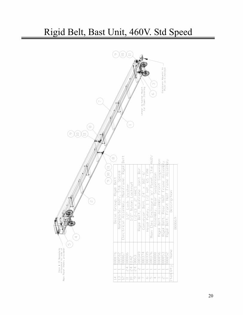
Rigid Belt, Bast Unit, 460V. Std Speed
21
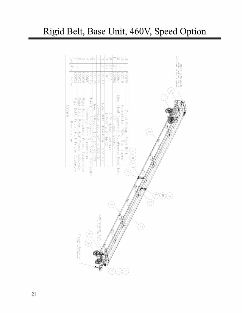
Rigid Belt, Base Unit, 460V, Speed Option
22
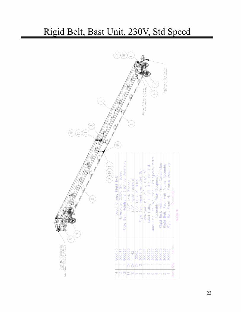
Rigid Belt, Bast Unit, 230V, Std Speed
23
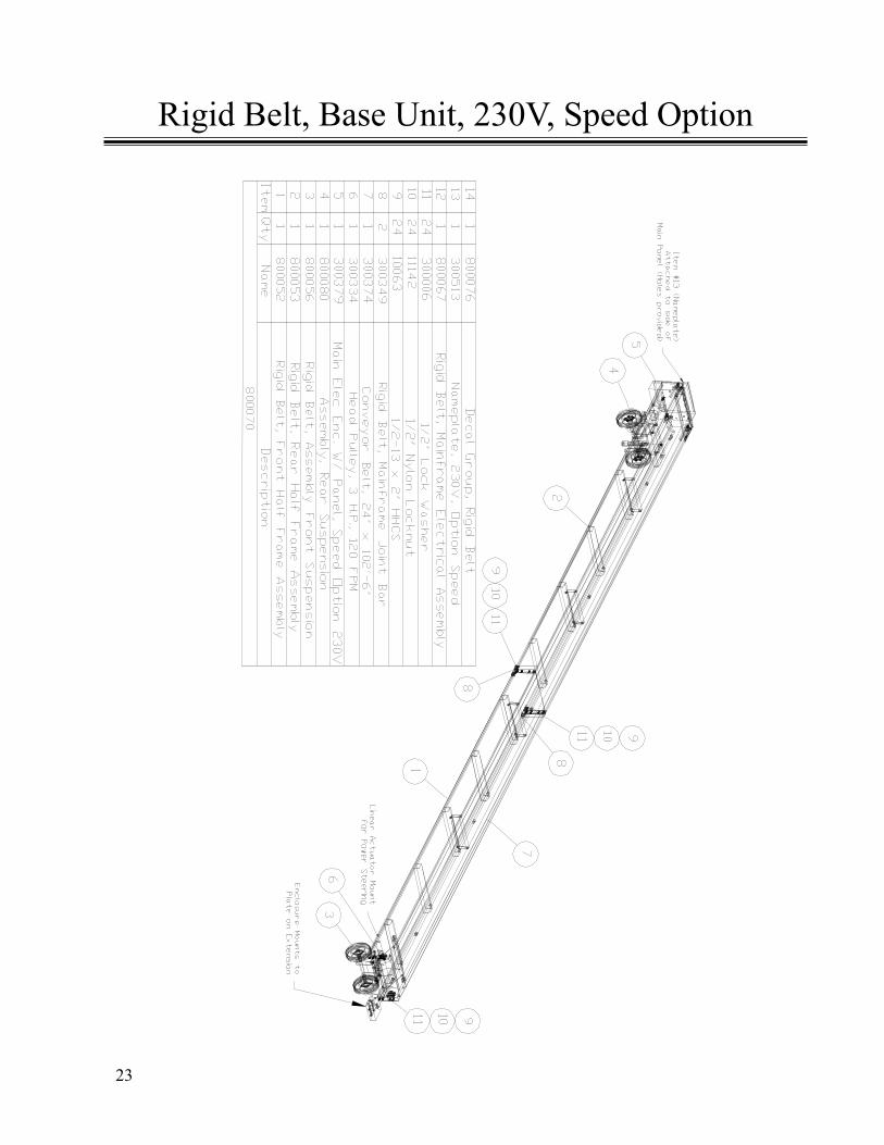
Rigid Belt, Base Unit, 230V, Speed Option
24
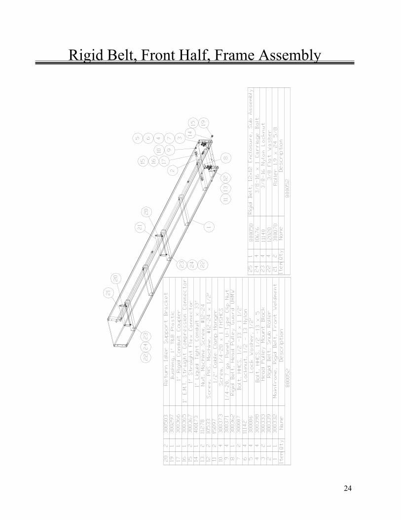
Rigid Belt, Front Half, Frame Assembly
25
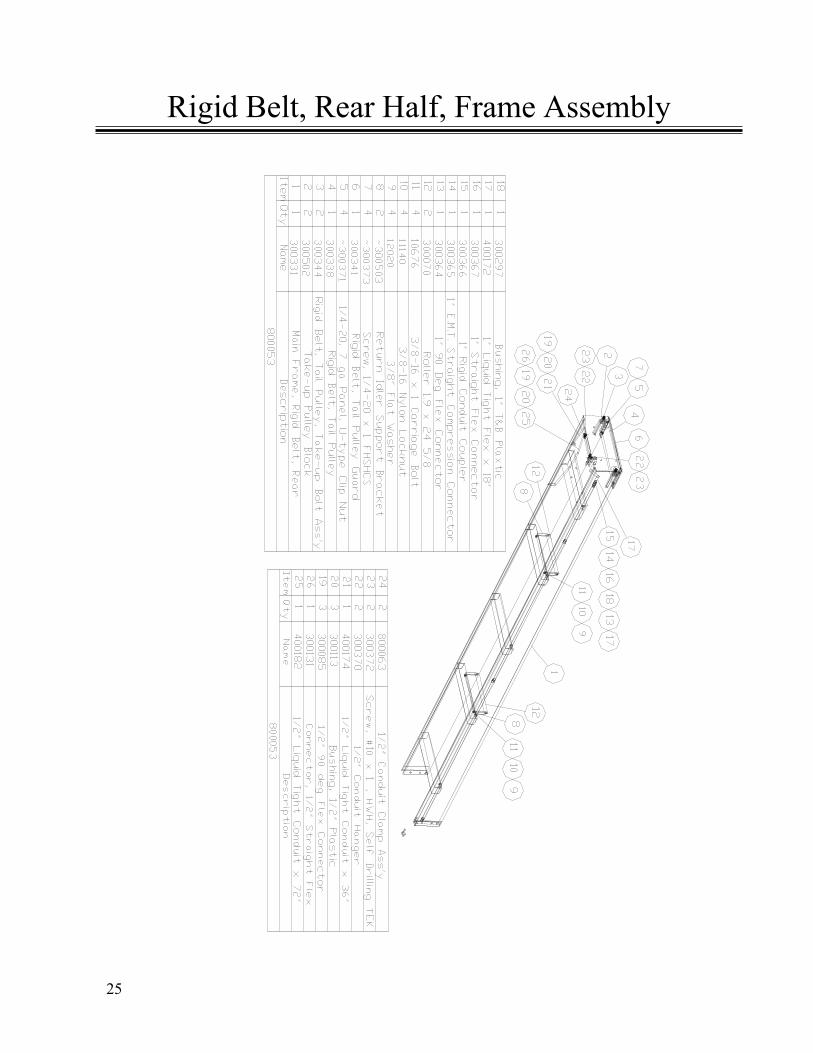
Rigid Belt, Rear Half, Frame Assembly
26
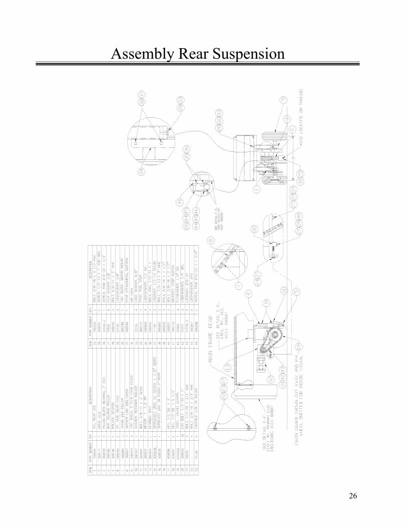
Assembly Rear Suspension
27
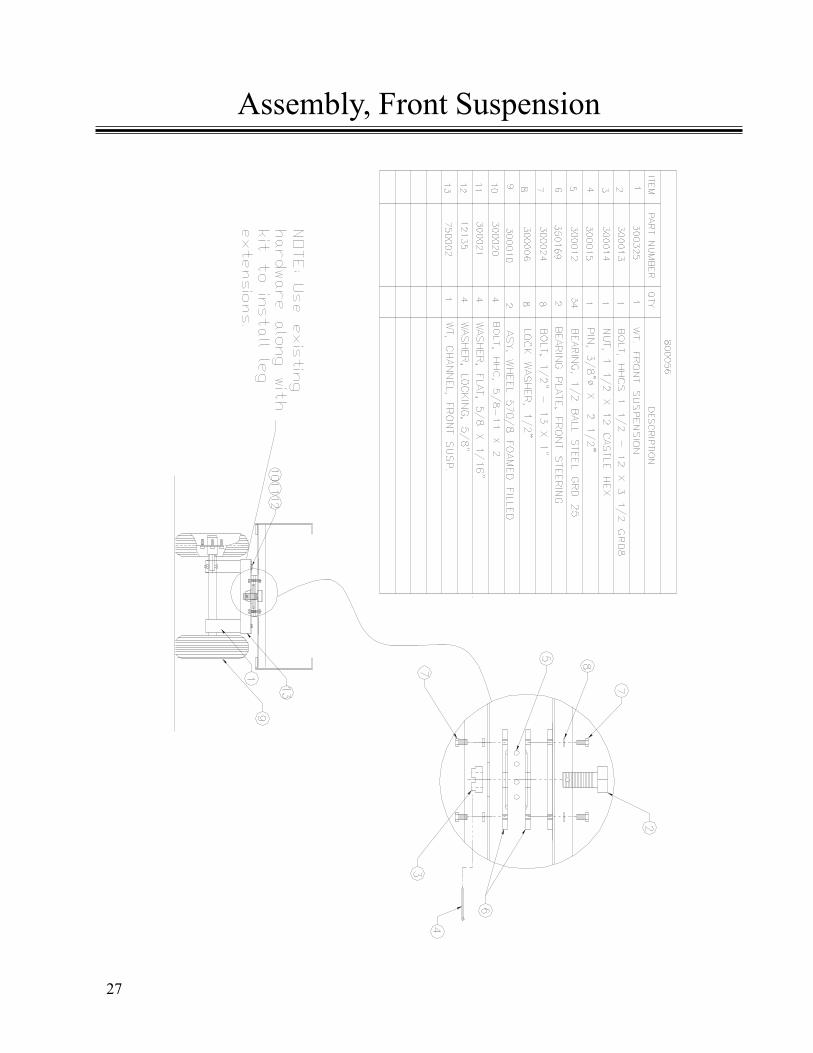
Assembly, Front Suspension
28
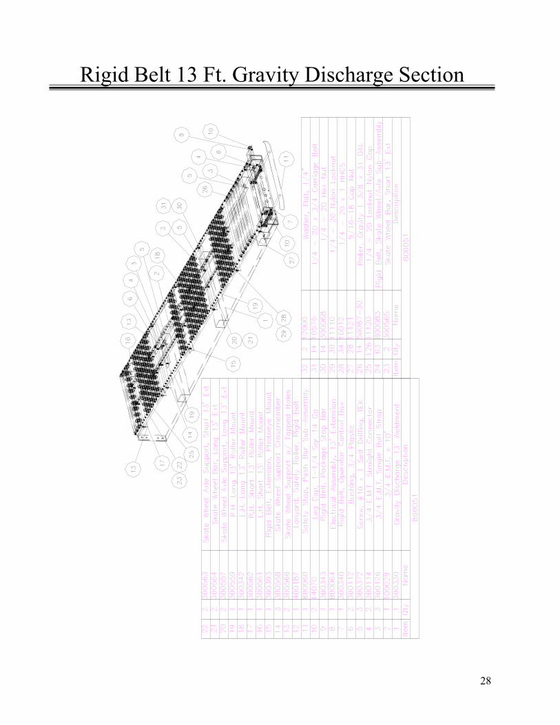
Rigid Belt 13 Ft. Gravity Discharge Section
29
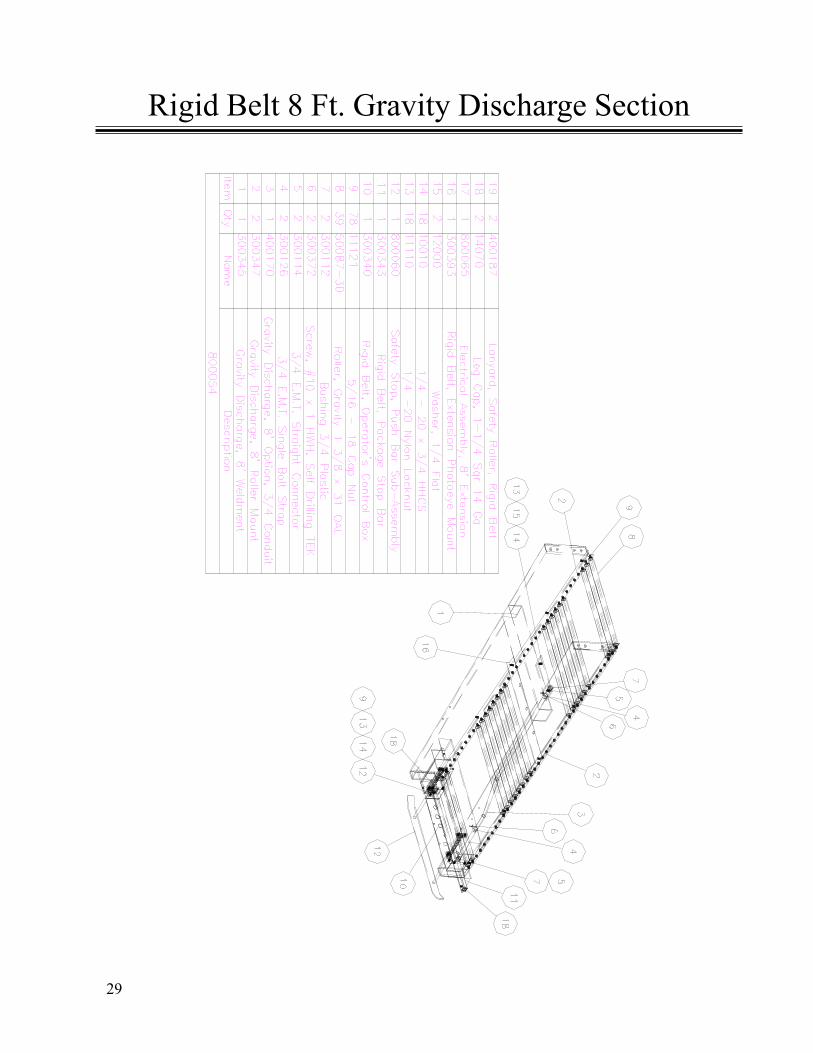
Rigid Belt 8 Ft. Gravity Discharge Section
30
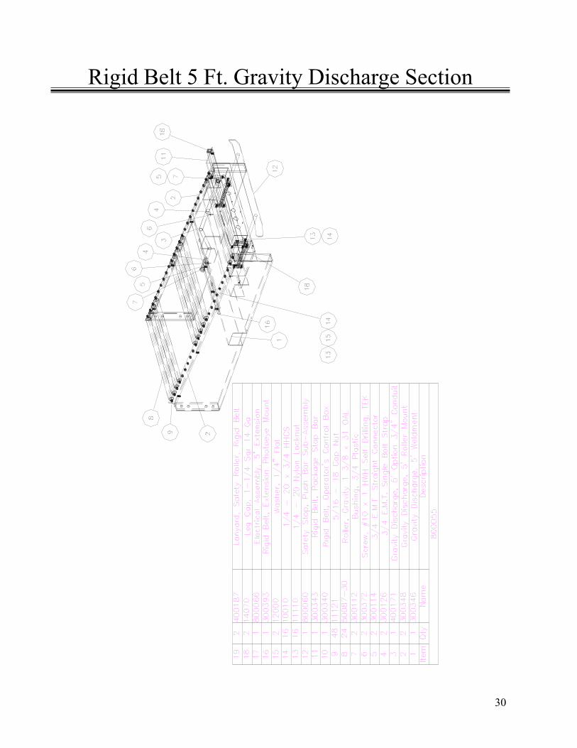
Rigid Belt 5 Ft. Gravity Discharge Section
31
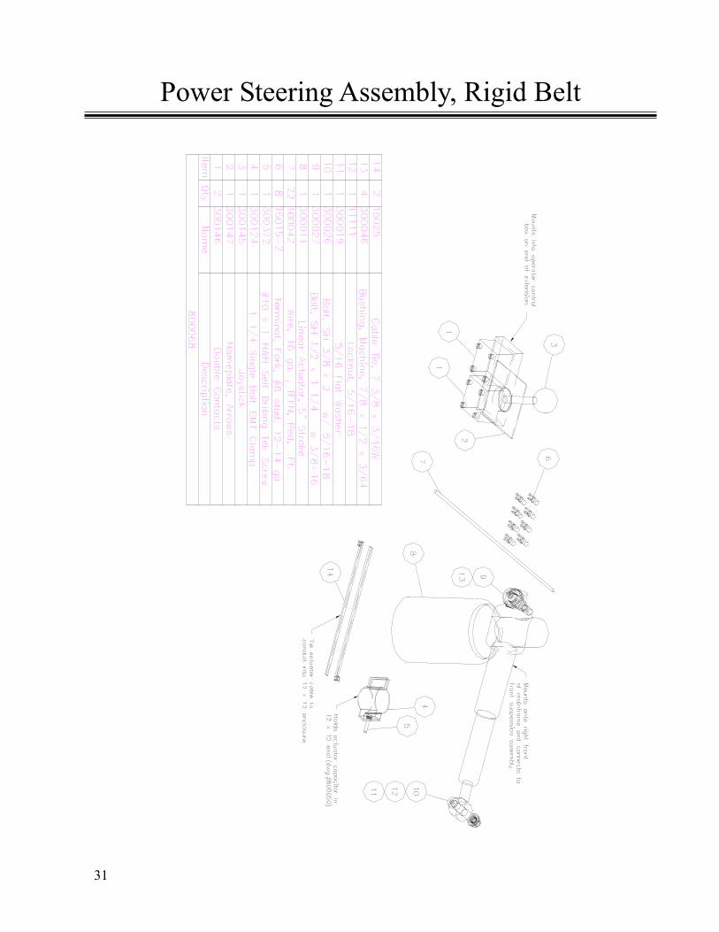
Power Steering Assembly, Rigid Belt
32
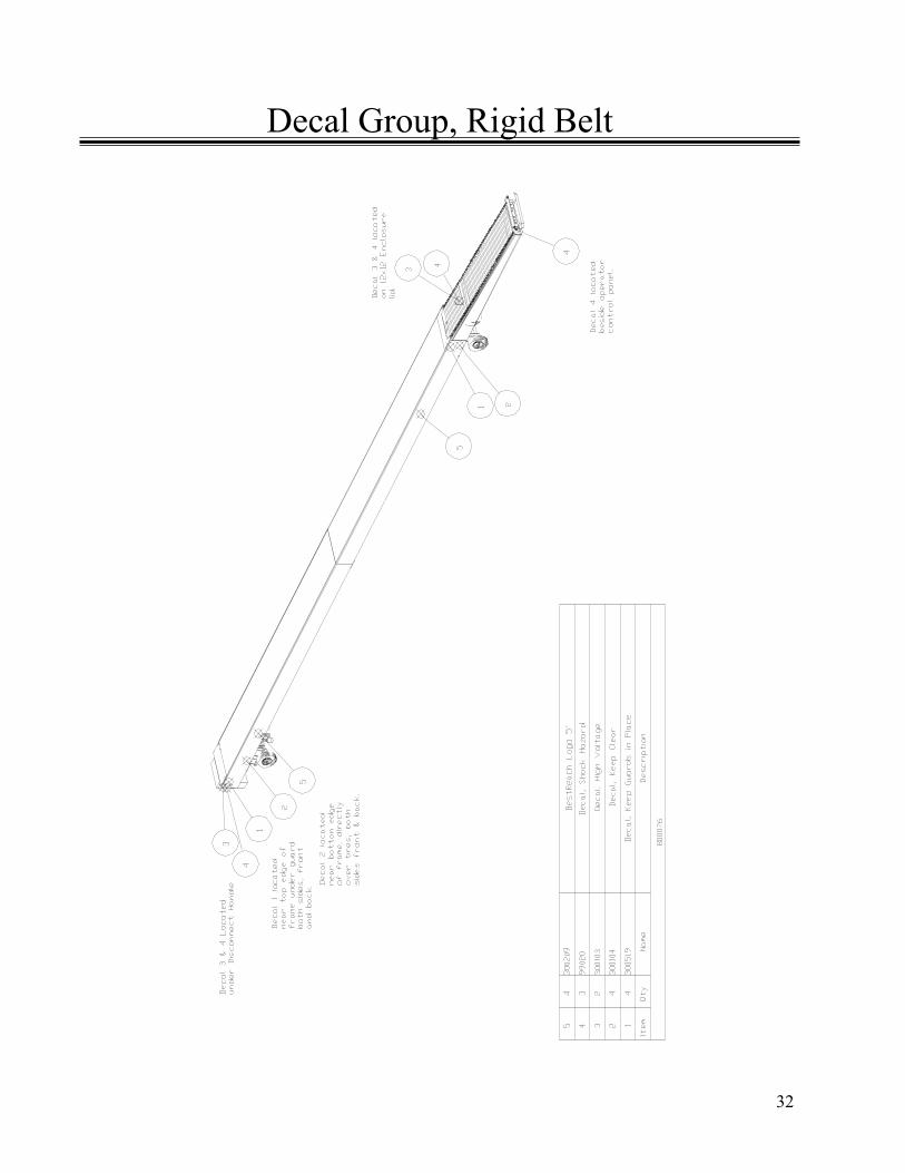
Decal Group, Rigid Belt

33
Rigid Belt, Manual Steering Option, 13 Ft.
34
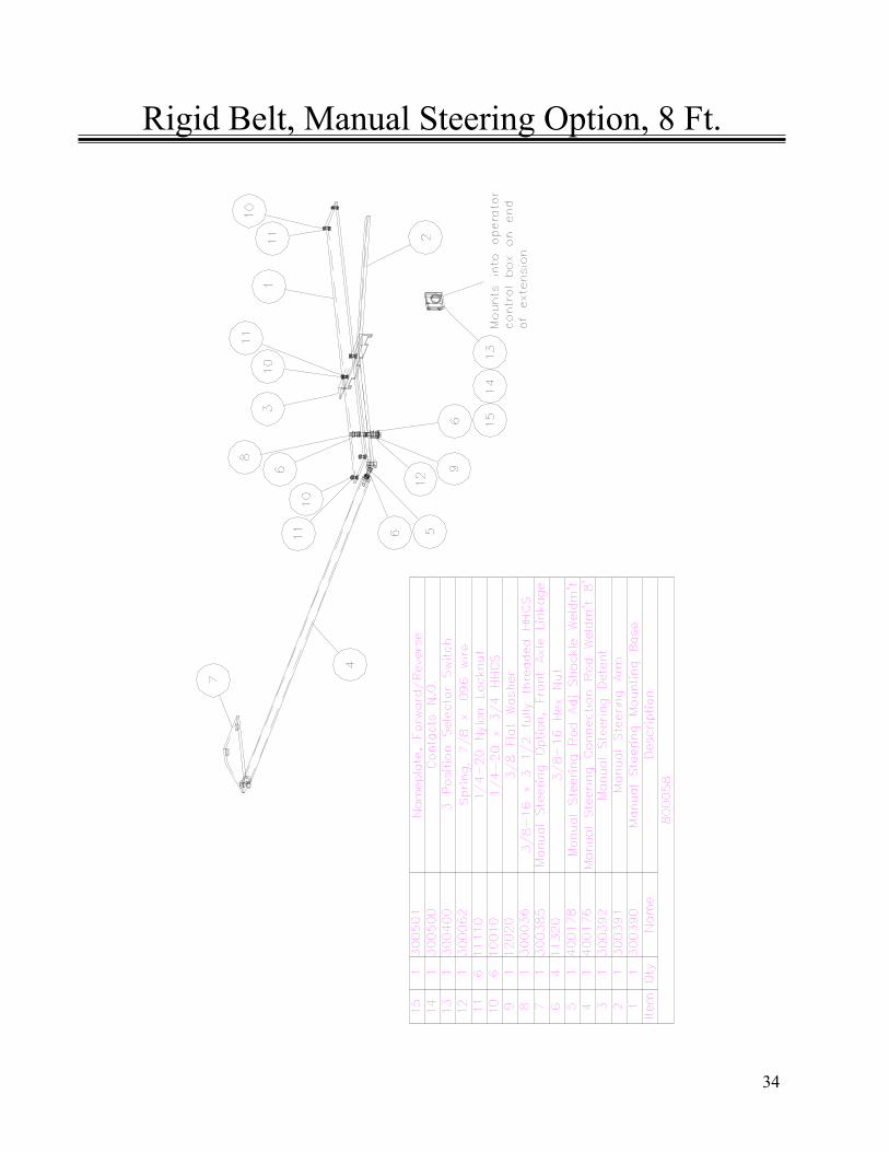
Rigid Belt, Manual Steering Option, 8 Ft.
35
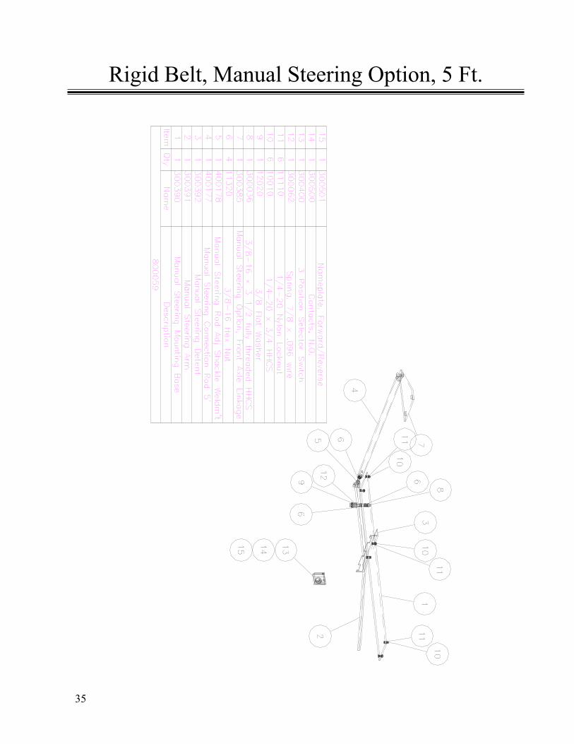
Rigid Belt, Manual Steering Option, 5 Ft.

36
Electrical Components
Assembly Diagrams of Electrical Components andParts List of BestReachTM Rigid Belt Conveyor.
37
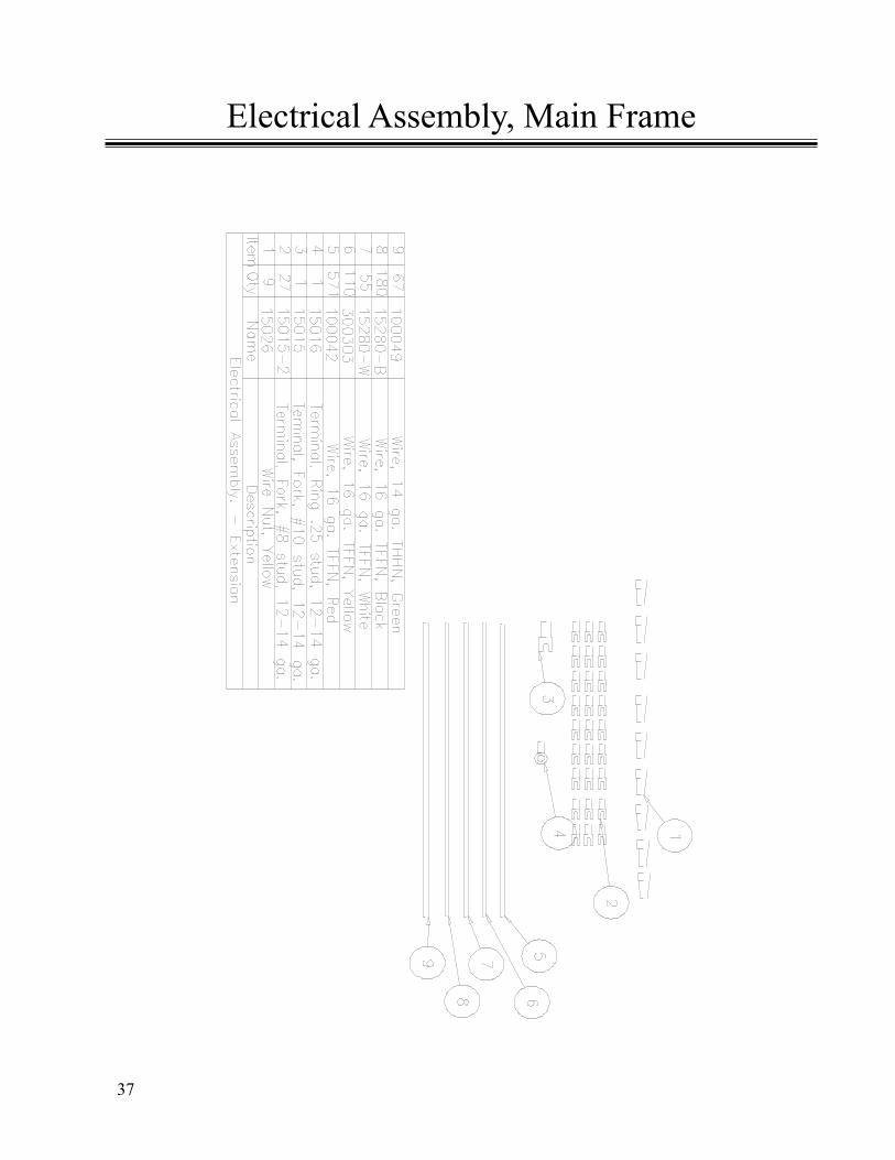
Electrical Assembly, Main Frame
38
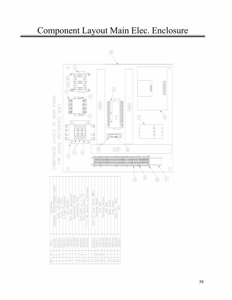
Component Layout Main Elec. Enclosure
39
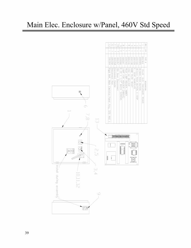
Main Elec. Enclosure w/Panel, 460V Std Speed

40
Main Electrical Panel Layout, 460V, Std Speed
41
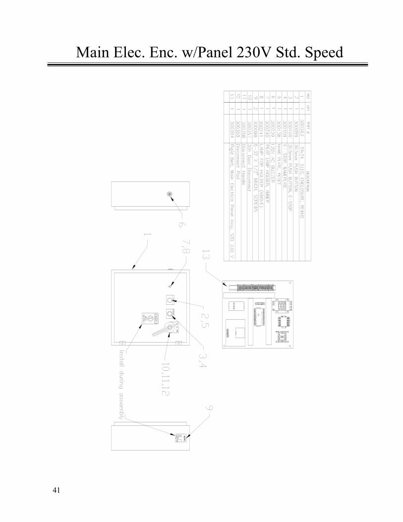
Main Elec. Enc. w/Panel 230V Std. Speed
42
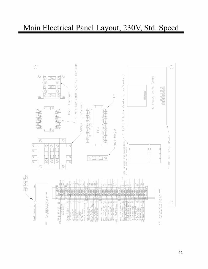
Main Electrical Panel Layout, 230V, Std. Speed

43
Main Elec. Enc. w/Panel, 460V Speed Opt.
44
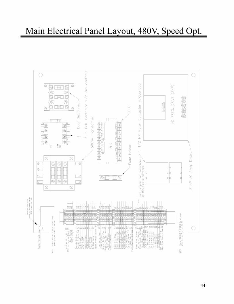
Main Electrical Panel Layout, 480V, Speed Opt.

45
Rigid Belt, Main Elec. w/Panel, 230V, Speed Opt.
46
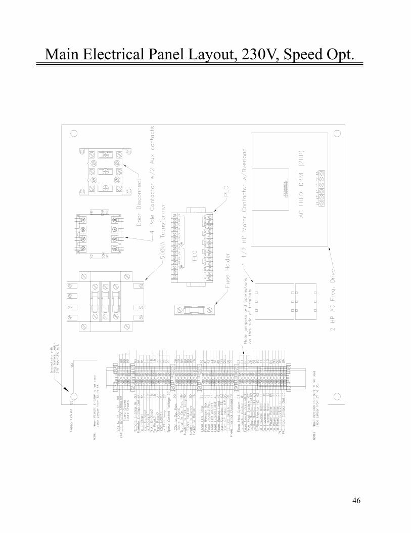
Main Electrical Panel Layout, 230V, Speed Opt.
47
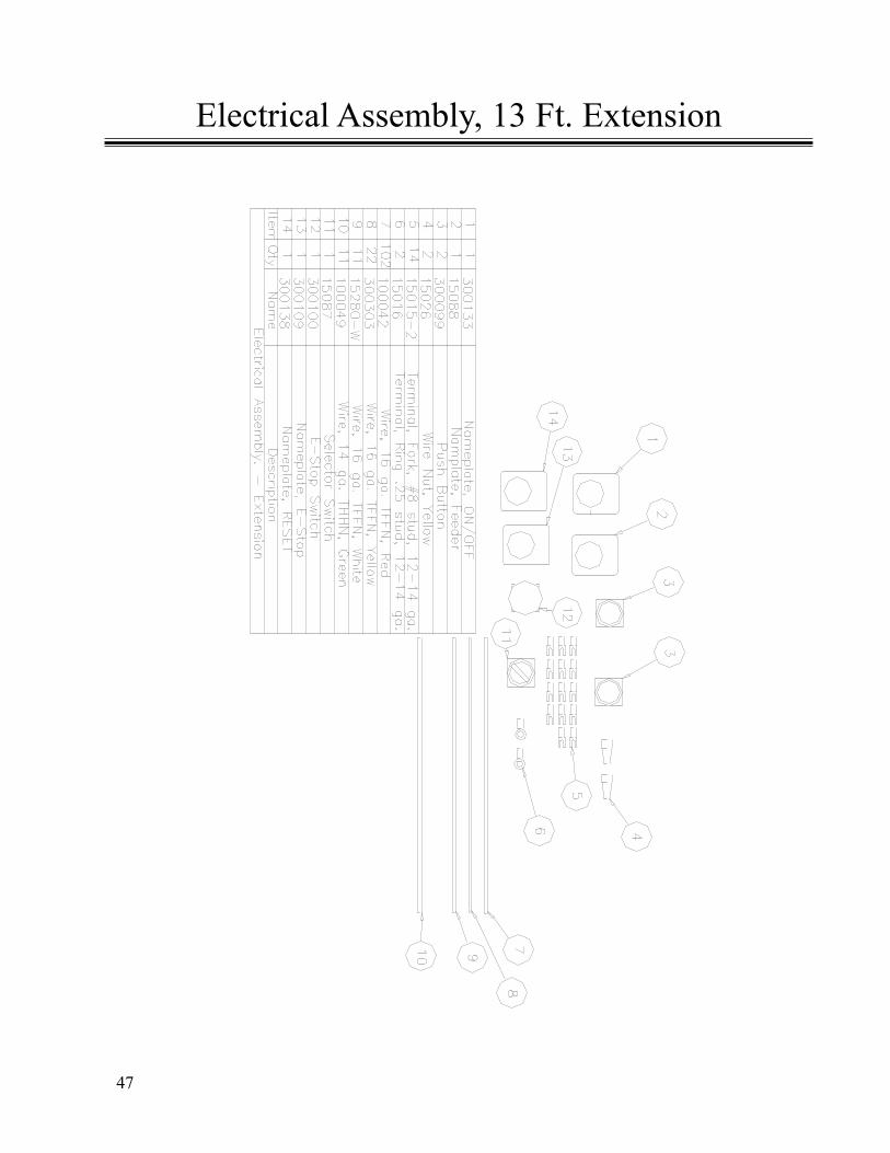
Electrical Assembly, 13 Ft. Extension
48
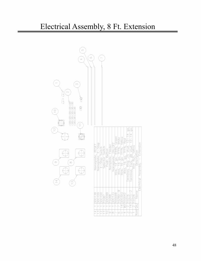
Electrical Assembly, 8 Ft. Extension

49
Electrical Assembly, 5 Ft. Extension

50
Schematics and Wire Connection Diagrams
BestReachTM Rigid Belt Schematics and WiringDiagrams
51
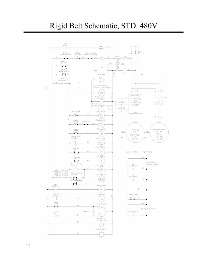
Rigid Belt Schematic, STD. 480V

52
Rigid Belt Schematic, STD. 240V
53
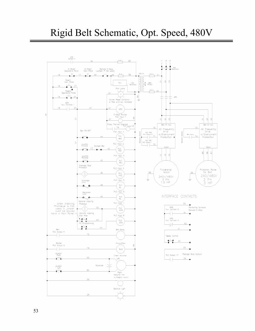
Rigid Belt Schematic, Opt. Speed, 480V
54
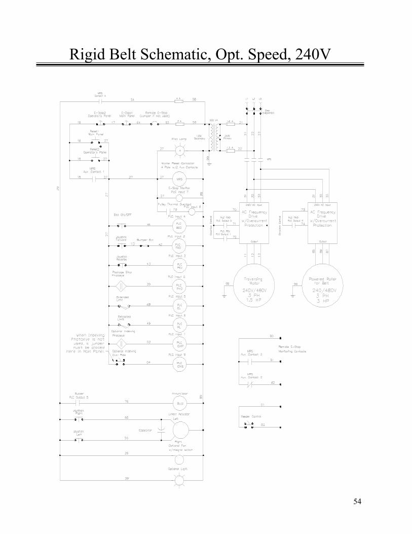
Rigid Belt Schematic, Opt. Speed, 240V
55
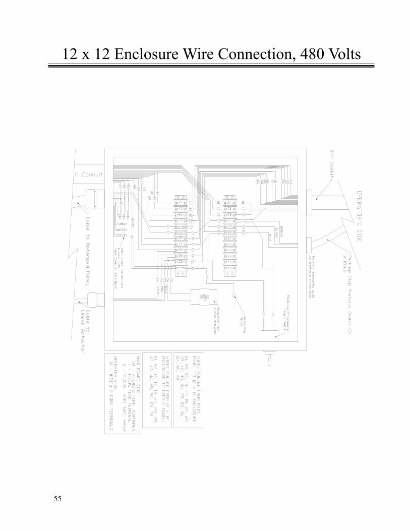
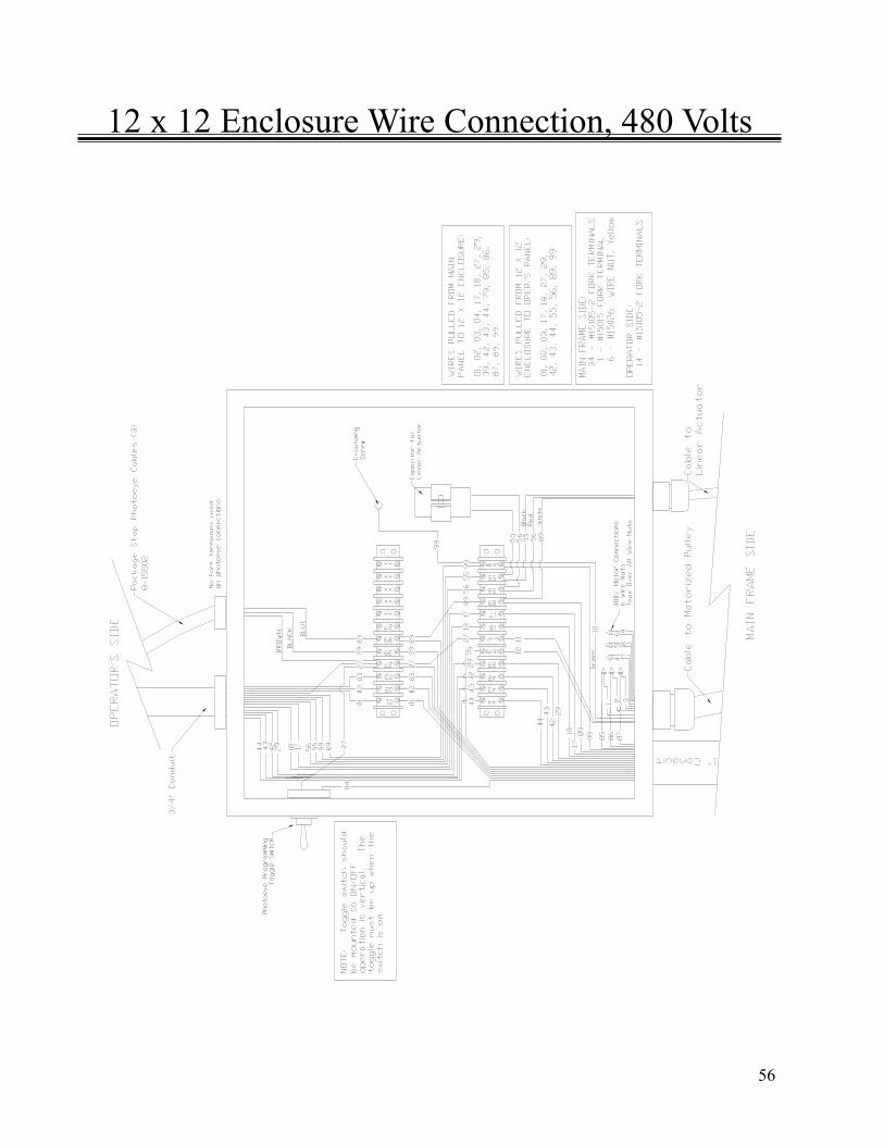
12 x 12 Enclosure Wire Connection, 480 Volts
56
12 x 12 Enclosure Wire Connection, 480 Volts
57
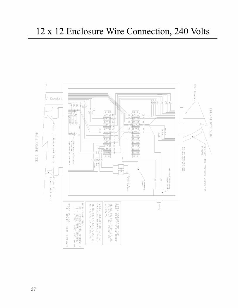
12 x 12 Enclosure Wire Connection, 240 Volts
58
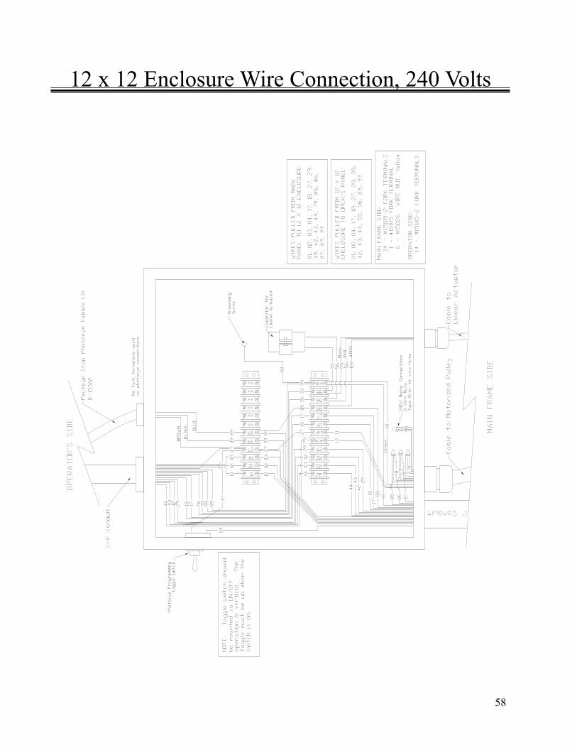
12 x 12 Enclosure Wire Connection, 240 Volts
59
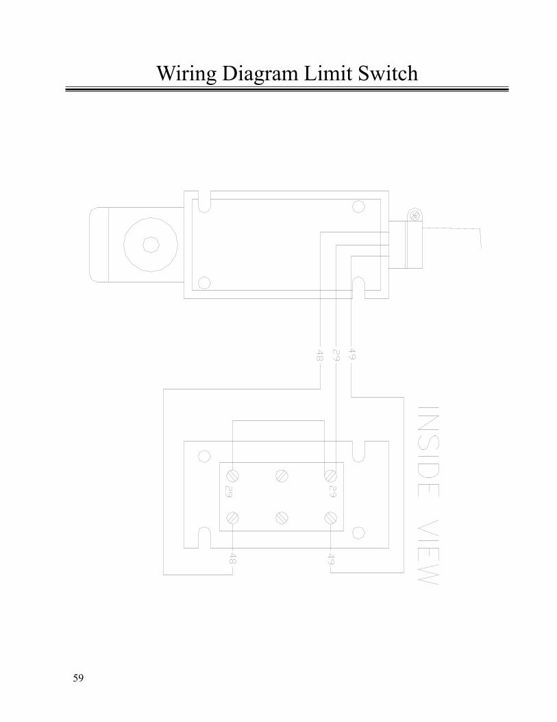
Wiring Diagram Limit Switch
60
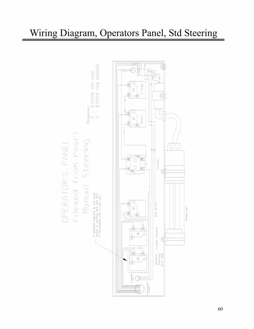
Wiring Diagram, Operators Panel, Std Steering

61
Operators Panel, Parts List, Std Steering
62
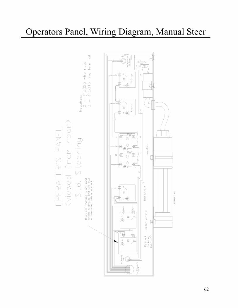
Operators Panel, Wiring Diagram, Manual Steer
63
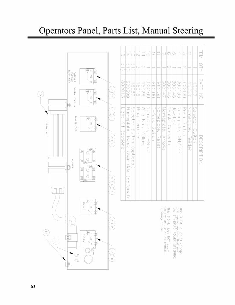
Operators Panel, Parts List, Manual Steering
64
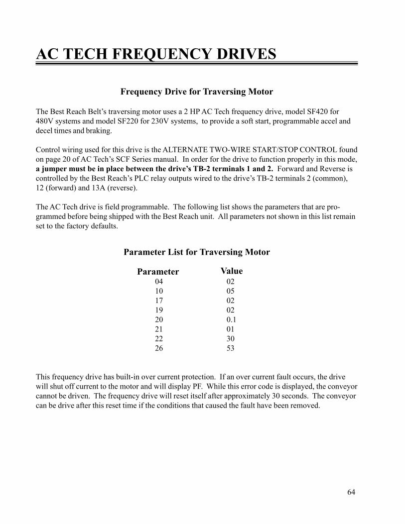
Frequency Drive for Traversing Motor
The Best Reach Belt’s traversing motor uses a 2 HP AC Tech frequency drive, model SF420 for480V systems and model SF220 for 230V systems, to provide a soft start, programmable accel anddecel times and braking.
Control wiring used for this drive is the ALTERNATE TWO-WIRE START/STOP CONTROL foundon page 20 of AC Tech’s SCF Series manual. In order for the drive to function properly in this mode,a jumper must be in place between the drive’s TB-2 terminals 1 and 2. Forward and Reverse iscontrolled by the Best Reach’s PLC relay outputs wired to the drive’s TB-2 terminals 2 (common),12 (forward) and 13A (reverse).
The AC Tech drive is field programmable. The following list shows the parameters that are pro-grammed before being shipped with the Best Reach unit. All parameters not shown in this list remainset to the factory defaults.
Parameter List for Traversing Motor
04 0210 0517 0219 0220 0.121 0122 3026 53
This frequency drive has built-in over current protection. If an over current fault occurs, the drivewill shut off current to the motor and will display PF. While this error code is displayed, the conveyorcannot be driven. The frequency drive will reset itself after approximately 30 seconds. The conveyorcan be drive after this reset time if the conditions that caused the fault have been removed.
AC TECH FREQUENCY DRIVES
ValueParameter

65
The frequency drive used to power the motorized head pulley for this option is the same as the driveused for the traversing motor except that it has a 3 HP rating instead of the traversing’s 2 HP.
Control wiring for this drive is the Two-Wire Start/Stop Control wiring found on page 19 of the ACTech SCF Series Manual. Reversing is not used for the conveyor belt. Therefore, a jumper is used toselect Forward only.
The parameters are different for this drive from the traversing drive’s parameters. All parameters notlisted here remain at the factory’s default values.
Parameter List for Optional Speed Belt Drive
19 02 20 0.1 23 36.0 24 64.8 26 100 39 125
With these parameters, the belt speed in feet per minute will be displayed on the frequency drive’sLED display when the belt is running. Belt speed may be adjusted by the up and down buttons on thefrequency drive. For more information on the drive consult the AC Tech Manual supplied with youconveyor.
WARNING: Voltage in the main electrical panel can cause injury or death. Viewing the fre-quency drive’s display and adjusting the belt speed requires the main electrical panel door be openwhile power is applied. This should only be done by trained and qualified personnel with approvalto work with live voltage. Follow all OSHA and other pertinent safety guidelines when servicingthis conveyor.
Frequency Drive for Optional Belt Speed
Parameter Value
66
WHEN NOTHING WILL RUNCheck:
• Remote disconnect fuses and disconnect is turned on• Conveyor’s door disconnect is turned on• E-Stops mushroom heads are out• Master reset circuit is on (amber pilot light on main electrical panel should be on)• Primary and secondary fuses for control transformer• Supply power wiring
CONVEYOR BELT WILL NOT RUNCheck:
• Master reset circuit is on (amber pilot light on main electrical panel should be on)• Bed On/Off contacts are making• Wiring from Bed On/Off contacts to PLC input• PLC output is making• Wiring between PLC output and bed contactor coil• Bed contactor’s overload has tripped• Bed contactor is making (check contacts and coil)• Motorized pulley thermal overload. The motorized pulley has a normally closed internalthermal overload switch. This switch is wired as an input to the PLC. If the pulley over heats andthe switch opens, the belt will shut off. If the Bed On/Off button is pushed while the thermaloverload switch is open (or the wiring to the switch is broken or not connected) the belt will notstart and the beeper will sound an error code of three beeps 2 seconds each separated by .5seconds.• Wiring between bed contactor and motorized pulley
Motorized pulley motor
Troubleshooting the Electrical System

67
CONVEYOR WILL NOT DRIVE FORWARD, BUT WILL DRIVE IN REVERSECheck:
• Bumper is not returning fully forward• Bumper switch is not making while bumper is fully forward• Extend limit switch is not returning to neutral position (center position)• Extend limit contacts in limit switch are closed (operator rod is on something or contacts arestuck)• Wiring between Forward contact (joystick or selector switch) and bumper switch• Wiring between bumper switch and PLC input
CONVEYOR WILL NOT DRIVE FORWARD OR REVERSECheck:
• Jumper on AC frequency drive’s terminals 1 and 2 (must be in place)• AC frequency drive’s common control wiring to Forward/Reverse contacts (joystick orselector switch)• AC frequency drive has faulted out (overload faults, shown as PF, will reset themselves inapproximately 30 seconds after no input to forward or reverse controls)• Three phase power to AC frequency drive• Output from AC frequency drive• Traversing Motor• Wiring from AC frequency drive to motor• Parameters in AC frequency drive have changed from values shown in list
CONVEYOR WILL NOT STEER LEFT OR RIGHT (power steering models only)Check:
• Power to joystick steering contacts, fuse in main electrical panel• Power through joystick contacts when steering• Power to linear actuator
Linear actuator capacitor
Troubleshooting the Electrical System (cont)

Best Diversified Products, Inc.107 Flint Street
Jonesboro, AR 72401Phone: 870-935-0970
Toll Free: 800-327-9209Fax: 870-935-3661
Call BEST Customer Service1-800-327-9209
99039