Embed Size (px)
Citation preview
Best Practice Guidelines for Safe (Un)Loading of
Road Freight Vehicles covering Technical, Behavioural and Organisational Aspects
Issue 1 - December 2013
2
Table of Contents
Table of Contents ____________________________________________________________ 2 Introduction ________________________________________________________________ 3 Scope and objectives _________________________________________________________ 3 Part A: Organizational and Behavioural aspects_____________________________________ 4 1. Behaviour Based Safety _________________________________________________ 4 2. Roles and responsibilities ________________________________________________ 9 3. SQAS and ESAD ______________________________________________________ 18 4. Emergency response plan _______________________________________________ 19 5. Applicable legislation ___________________________________________________ 21 6. Communication skills of drivers and operators _______________________________ 22 Part B: Technical aspects _____________________________________________________ 23 7. Technical requirements (un)loading sites ___________________________________ 23 8. SULID: Site (Un)Loading Information Document _____________________________ 24 9. Information, instructions and training for drivers and operators _________________ 26 10. Personal Protective Equipment (PPE) ______________________________________ 30 11. Unloading scenario’s bulk liquid __________________________________________ 33 12. Couplings and hoses for bulk liquids and gasses _____________________________ 37 Contact list ________________________________________________________________ 45 Part C: Annexes ____________________________________________________________ 46 1. Annex 1: Example Risk assessment for Bulk Solids Unloading sites ______________ 46 2. Annex 2: Pictorial examples of Access/ Egress to the (un)loading area ____________ 47 3. Annex 3: Examples Behaviour Based Safety Observation reports ________________ 49 4. Annex 4: Roles and Tasks for load securing in Cargo Transport Units _____________ 52 5. Annex 5: Hierarchy and lists of applicable legislation __________________________ 53 6. Annex 6: Best Practice Guidelines ________________________________________ 57 7. Annex 7: Examples of Risks and Risk mitigation for (un)loading operations ________ 58 8. Annex 8: (Un)loading expressions / list in English ____________________________ 64 9. Annex 9: Examples of pictographic loading instructions ________________________ 65
DISCLAIMER This document is intended for information only and sets out guidelines for the safe (un)loading of road freight vehicles (bulk, packed & liquid). The information provided in these guidelines is provided in good faith and, while it is accurate as far as the authors are aware, no representations or warranties are made with regards to its completeness. It is not intended to be a comprehensive guide for the (un)loading of road freight vehicles (bulk, packed & liquid). No responsibility will be assumed by the participating associations (CEFIC, ECTA, FECC) in relation to the information contained in these Guidelines. Each company should decide based on their own decision-making process to apply the guidance contained in this document, in full, partly or to adopt other measures.
3
Introduction
Continuous efforts to improve safety during the transport and the associated handling of chemicals are part of the overall aim to improve safety performance of both the chemical industry and the transport industry.
Statistical analysis of accidents indicates that 80% of transport-related incidents and accidents occur during loading and unloading operations. Further detailed analysis shows that in 90% of these cases, the human factor is the root cause. It is therefore essential to increase safety during loading and unloading. These guidelines offer best practice guidance regarding the safety of loading and unloading operations of road freight vehicles from an organizational, behavioural and technical point of view.
Guidance on processes and equipment should reduce the number and consequences of interface mismatches, thus intrinsically improving the safety of (un)loading operations and therefore the entire supply chain.
The previous guideline: Behaviour Based Safety Guidelines for the safe loading & unloading of road freight vehicles. Issue 2 March 2007 served our industries well in providing a clear guidance on who is to be expected to perform what task thereby largely standardising the organisational part of the (un)loading process. That part of the guideline is a best practice now and makes its appearance again in chapter 2 Roles and responsibilities of this revised guideline with some minor additions and clarifications.
The implementation of a Behaviour Based Safety management system has proven to be very effective in reducing incidents on chemical manufacturing sites but only makes it first steps in the logistics industry today. Chapter 1: Behaviour Based Safety of this guideline shows the reader the industry’s best practice today and is a significant development of the second chapter of the previous ‘BBS guideline’.
More technical best practices on standardisation of equipment (i.e. Technical requirements, PPE, couplings) and processes (i.e. SULID, info and instructions, communication) can be found in Part B: Technical aspects of the document.
In all circumstances, the applicable national or international regulations take precedence over the recommendations made in these guidelines. The guidelines are of a voluntary nature. Individual companies may decide to apply the guidelines either in full, or partly, according to their own judgment and in light of the specific circumstances.
The writing of guidelines in itself is the subject of continuous improvement. This guideline is not meant to be printed on 66 glossy pages. The guideline contains several cross references and external hyperlinks and is designed to live its life in the virtual world.
Feedback, suggestions on broken links and updates can be sent to vtr cefic.be
Steven Beddegenoodts, Chairman of the workgroup
Scope and objectives
The objective of these guidelines is to provide assistance in the prevention or elimination of unsafe conditions and situations during (un)loading operations by promoting best practice, recognizing the need for interaction between the different parties involved.
The scope of the these guidelines includes the safe loading and unloading of chemical products by operators and drivers at production sites, storage terminals, warehouses and customers, and covers the loading and unloading of liquid bulk, dry bulk as well as packed goods.
@
Chapter 1 Behaviour Based Safety - Issue 1 - December 2013 4
Part A: Organizational and Behavioural Aspects
A safety management system is meant to identify hazards, to control risks and to measure effectiveness of mitigating actions. The safety management system therefore should also cover the entire (un)loading operation from gate to gate and take into account each of the subsequent chapters of this document. These include ‘Behaviour based safety’, ‘Roles and responsibilities’, ‘SQAS and ESAD’, ‘Emergency response plan’, ‘Applicable legislation’ and ‘Communication skills of drivers and operators’.
1. Behaviour Based Safety
Behaviour Based Safety (BBS) is a safety management practice that has originally been used in the process industry to improve the safety level on the work floor. This guideline strongly suggests application of this system to the (un)loading operation.
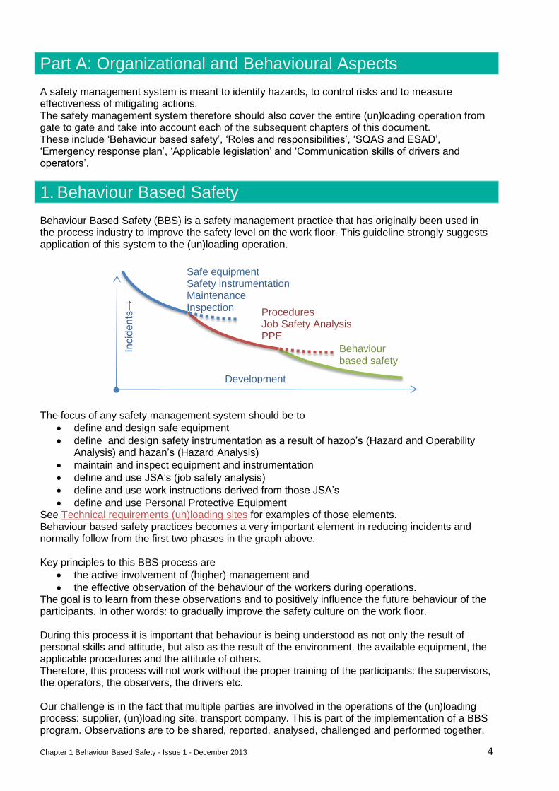
The focus of any safety management system should be to
define and design safe equipment
define and design safety instrumentation as a result of hazop’s (Hazard and Operability Analysis) and hazan’s (Hazard Analysis)
maintain and inspect equipment and instrumentation
define and use JSA’s (job safety analysis)
define and use work instructions derived from those JSA’s
define and use Personal Protective Equipment See Technical requirements (un)loading sites for examples of those elements. Behaviour based safety practices becomes a very important element in reducing incidents and normally follow from the first two phases in the graph above. Key principles to this BBS process are
the active involvement of (higher) management and
the effective observation of the behaviour of the workers during operations. The goal is to learn from these observations and to positively influence the future behaviour of the participants. In other words: to gradually improve the safety culture on the work floor. During this process it is important that behaviour is being understood as not only the result of personal skills and attitude, but also as the result of the environment, the available equipment, the applicable procedures and the attitude of others. Therefore, this process will not work without the proper training of the participants: the supervisors, the operators, the observers, the drivers etc. Our challenge is in the fact that multiple parties are involved in the operations of the (un)loading process: supplier, (un)loading site, transport company. This is part of the implementation of a BBS program. Observations are to be shared, reported, analysed, challenged and performed together.
Incid
ents
→
Development
Safe equipment Safety instrumentation Maintenance Inspection Procedures
Job Safety Analysis PPE
Behaviour based safety
Chapter 1 Behaviour Based Safety - Issue 1 - December 2013 5
All parties in the process have a common interest in increasing the safety level of the operations. The next pages provide practical tools and a guideline for the implementation of a BBS program. Using the step by step approach below should facilitate any organization in determining its level with regards to the implementation process. The levels can be used as an evaluation tool by all parties.
1.1. BBS at Level 1
1. There is a strong safety management system in place which includes:
a safety policy signed by the management
regular safety meetings
safety training programs
involvement of all personnel to improve safety (near miss reporting system)
written procedures and instructions
regular communication of safety matters to all employees This system is evaluated internally on a regular basis and improvement action plans are in place.
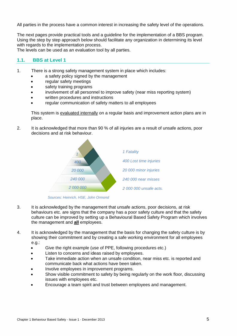
2. It is acknowledged that more than 90 % of all injuries are a result of unsafe actions, poor decisions and at risk behaviour.
3. It is acknowledged by the management that unsafe actions, poor decisions, at risk
behaviours etc. are signs that the company has a poor safety culture and that the safety culture can be improved by setting up a Behavioural Based Safety Program which involves the management and all employees.
4. It is acknowledged by the management that the basis for changing the safety culture is by showing their commitment and by creating a safe working environment for all employees e.g.:
Give the right example (use of PPE, following procedures etc.)
Listen to concerns and ideas raised by employees.
Take immediate action when an unsafe condition, near miss etc. is reported and communicate back what actions have been taken.
Involve employees in improvement programs.
Show visible commitment to safety by being regularly on the work floor, discussing issues with employees etc.
Encourage a team spirit and trust between employees and management.
1 Fatality 400 Lost time injuries 20 000 minor injuries 240 000 near misses 2 000 000 unsafe acts.
Sources: Heinrich, HSE, John Ormond
2 000 000
240 000
20 000
400
1
Chapter 1 Behaviour Based Safety - Issue 1 - December 2013 6
1.2. BBS at Level 2
= Level 1 plus the following items 1. Someone is assigned to lead the BBS program. This can be an internal or an external
specialist who has been trained in BBS improvement programs.
2. Identify for all the activities, a list of critical (at risk) safe and unsafe behaviours. This can be done by using incident investigation reports, near miss reports and risk assessments. This is accomplished through involvement of a multi-disciplinary team of the workforce. This list will make clear to all employees what ‘at risk’ behaviour is, e.g.
Driving a forklift without adequate visibility to crossing traffic.
Failure to check the working conditions when issuing a Permit-To-Work (e.g. presence of flammable material when doing hot work.)
Failure to isolate electrical equipment before starting the job.
Failure to use the life line system when going on top of a truck.
By-passing a safety device (e.g. light cells). 3. Give training to the management and all employees on the BBS system:
why the system has been set up
the commitment of the management to make it a success
how the system works
what the expected outcome is
what the role of all employees is
Chapter 1 Behaviour Based Safety - Issue 1 - December 2013 7
1.3. BBS at Level 3
= Level 2 plus the following items 1. Assign people within all layers of the organization to do behavioural observation rounds.
Organize training on:
what are ‘at risk’ behaviours
observation techniques
how to approach people that were observed (how to give positive reinforcement, how to coach them to change their behaviour)
how to report
2. Set up a system of behavioural observations:
Make a plan.
Set targets and goals.
Trained observers observe the work force and record ‘safe’ / ‘at risk’ behaviours.
Use the list of ‘at risk behaviours’ as guidance.
Give immediate feedback to the person that was observed.
Give positive reinforcement when safe behaviours are observed.
Provide coaching/correction when at risk behaviours are observed (stop the activity when necessary), explain what could be the consequence of the unsafe behaviour.
Focus on safe behaviours.
Write a report. 3. Collect, record and analyse observation data.
Look for trends. Try to understand why people behave in a certain way and what can be done to improve.
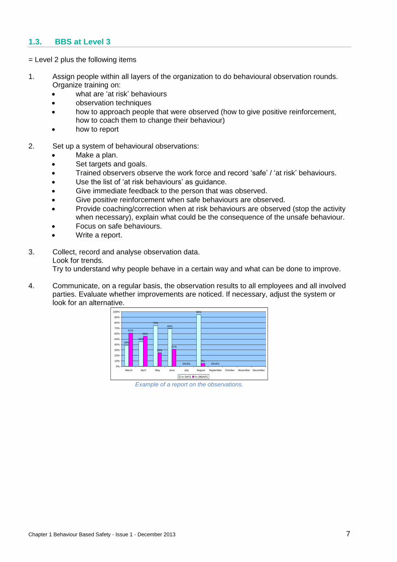
4. Communicate, on a regular basis, the observation results to all employees and all involved parties. Evaluate whether improvements are noticed. If necessary, adjust the system or look for an alternative.
Example of a report on the observations.
39%
45%
75%
69%
0%
95%
0%
61%
55%
25%
31%
0%5%
0%0%
10%
20%
30%
40%
50%
60%
70%
80%
90%
100%
March April May June July August September October November December
% SAFE % UNSAFE
Chapter 1 Behaviour Based Safety - Issue 1 - December 2013 8
1.4. BBS at Level 4
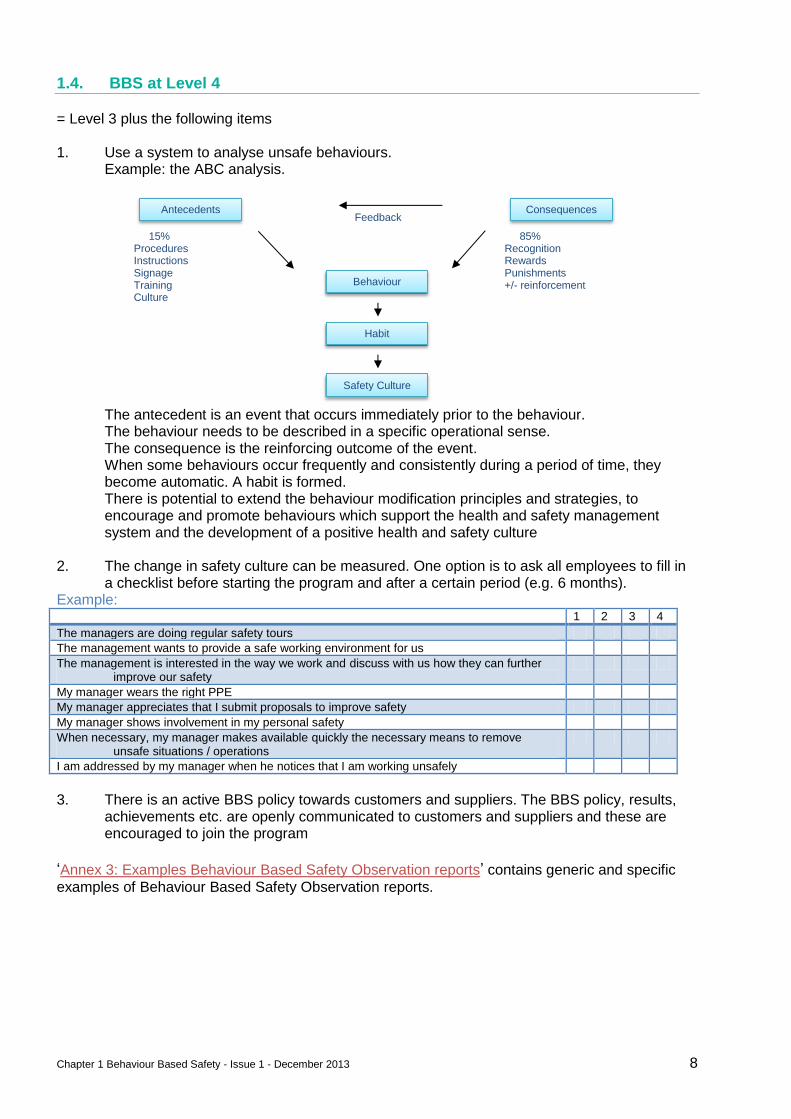
= Level 3 plus the following items 1. Use a system to analyse unsafe behaviours.
Example: the ABC analysis.
Feedback
15% Procedures Instructions Signage Training Culture
85% Recognition Rewards Punishments +/- reinforcement
The antecedent is an event that occurs immediately prior to the behaviour. The behaviour needs to be described in a specific operational sense. The consequence is the reinforcing outcome of the event. When some behaviours occur frequently and consistently during a period of time, they become automatic. A habit is formed. There is potential to extend the behaviour modification principles and strategies, to encourage and promote behaviours which support the health and safety management system and the development of a positive health and safety culture
2. The change in safety culture can be measured. One option is to ask all employees to fill in a checklist before starting the program and after a certain period (e.g. 6 months).
Example: 1 2 3 4
The managers are doing regular safety tours
The management wants to provide a safe working environment for us
The management is interested in the way we work and discuss with us how they can further improve our safety
My manager wears the right PPE
My manager appreciates that I submit proposals to improve safety
My manager shows involvement in my personal safety
When necessary, my manager makes available quickly the necessary means to remove unsafe situations / operations
I am addressed by my manager when he notices that I am working unsafely
3. There is an active BBS policy towards customers and suppliers. The BBS policy, results,
achievements etc. are openly communicated to customers and suppliers and these are encouraged to join the program
‘Annex 3: Examples Behaviour Based Safety Observation reports’ contains generic and specific
examples of Behaviour Based Safety Observation reports.
Antecedents Consequences
Behaviour
Habit
Safety Culture
Chapter 2 Roles and responsibilities - Issue 1 December 2013 9
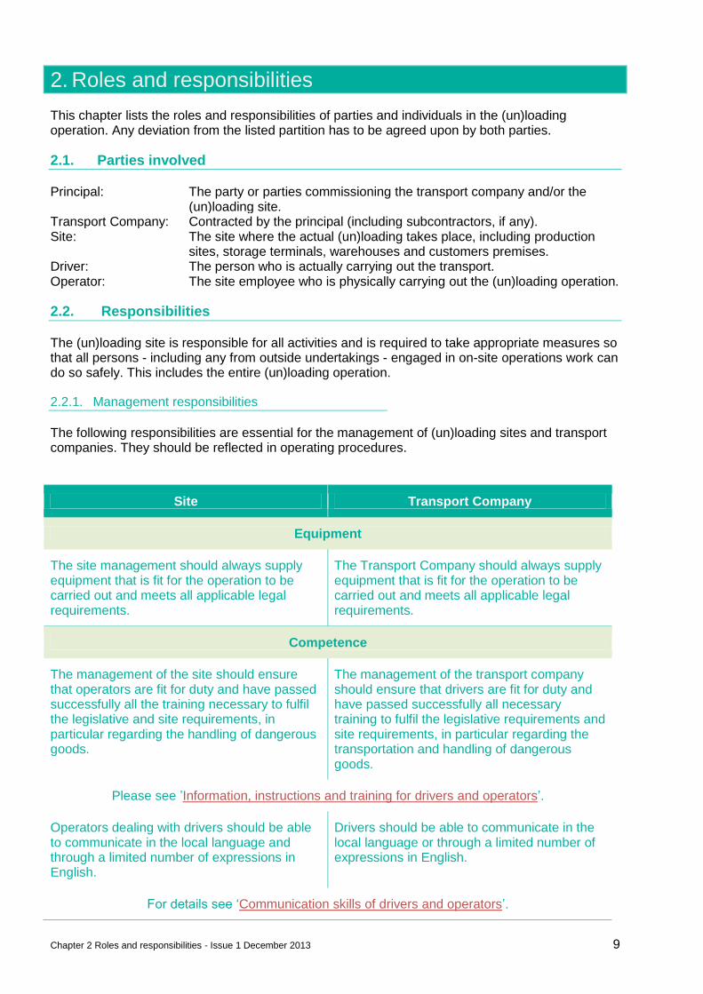
2. Roles and responsibilities
This chapter lists the roles and responsibilities of parties and individuals in the (un)loading operation. Any deviation from the listed partition has to be agreed upon by both parties.
2.1. Parties involved
Principal: The party or parties commissioning the transport company and/or the (un)loading site.
Transport Company: Contracted by the principal (including subcontractors, if any). Site: The site where the actual (un)loading takes place, including production
sites, storage terminals, warehouses and customers premises. Driver: The person who is actually carrying out the transport. Operator: The site employee who is physically carrying out the (un)loading operation.
2.2. Responsibilities
The (un)loading site is responsible for all activities and is required to take appropriate measures so that all persons - including any from outside undertakings - engaged in on-site operations work can do so safely. This includes the entire (un)loading operation.
2.2.1. Management responsibilities
The following responsibilities are essential for the management of (un)loading sites and transport companies. They should be reflected in operating procedures.
Site Transport Company
Equipment
The site management should always supply equipment that is fit for the operation to be carried out and meets all applicable legal requirements.
The Transport Company should always supply equipment that is fit for the operation to be carried out and meets all applicable legal requirements.
Competence
The management of the site should ensure that operators are fit for duty and have passed successfully all the training necessary to fulfil the legislative and site requirements, in particular regarding the handling of dangerous goods.
The management of the transport company should ensure that drivers are fit for duty and have passed successfully all necessary training to fulfil the legislative requirements and site requirements, in particular regarding the transportation and handling of dangerous goods.
Please see ’Information, instructions and training for drivers and operators’.
Operators dealing with drivers should be able to communicate in the local language and through a limited number of expressions in English.
Drivers should be able to communicate in the local language or through a limited number of expressions in English.
For details see ‘Communication skills of drivers and operators’.
Chapter 2 Roles and responsibilities - Issue 1 December 2013 10
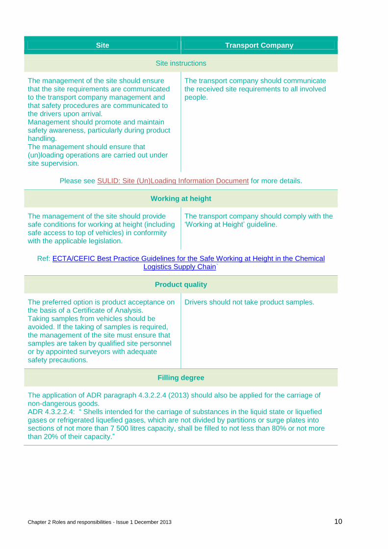
Site Transport Company
Site instructions
The management of the site should ensure that the site requirements are communicated to the transport company management and that safety procedures are communicated to the drivers upon arrival. Management should promote and maintain safety awareness, particularly during product handling. The management should ensure that (un)loading operations are carried out under site supervision.
The transport company should communicate the received site requirements to all involved people.
Please see SULID: Site (Un)Loading Information Document for more details.
Working at height
The management of the site should provide safe conditions for working at height (including safe access to top of vehicles) in conformity with the applicable legislation.
The transport company should comply with the ‘Working at Height’ guideline.
Ref: ECTA/CEFIC Best Practice Guidelines for the Safe Working at Height in the Chemical Logistics Supply Chain`
Product quality
The preferred option is product acceptance on the basis of a Certificate of Analysis. Taking samples from vehicles should be avoided. If the taking of samples is required, the management of the site must ensure that samples are taken by qualified site personnel or by appointed surveyors with adequate safety precautions.
Drivers should not take product samples.
Filling degree
The application of ADR paragraph 4.3.2.2.4 (2013) should also be applied for the carriage of non-dangerous goods. ADR 4.3.2.2.4: “ Shells intended for the carriage of substances in the liquid state or liquefied gases or refrigerated liquefied gases, which are not divided by partitions or surge plates into sections of not more than 7 500 litres capacity, shall be filled to not less than 80% or not more than 20% of their capacity.”
Chapter 2 Roles and responsibilities - Issue 1 December 2013 11
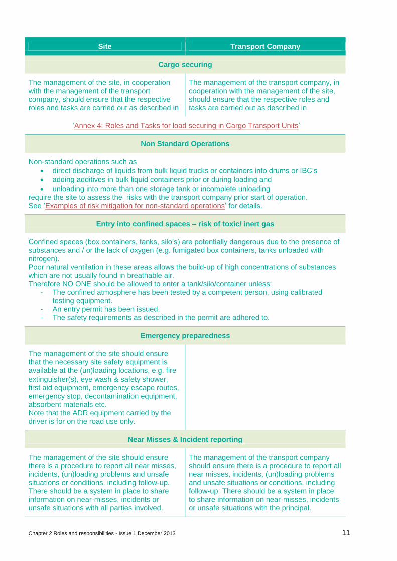
Site Transport Company
Cargo securing
The management of the site, in cooperation with the management of the transport company, should ensure that the respective roles and tasks are carried out as described in
The management of the transport company, in cooperation with the management of the site, should ensure that the respective roles and tasks are carried out as described in
‘Annex 4: Roles and Tasks for load securing in Cargo Transport Units’
Non Standard Operations
Non-standard operations such as
direct discharge of liquids from bulk liquid trucks or containers into drums or IBC’s
adding additives in bulk liquid containers prior or during loading and
unloading into more than one storage tank or incomplete unloading require the site to assess the risks with the transport company prior start of operation. See ’Examples of risk mitigation for non-standard operations’ for details.
Entry into confined spaces – risk of toxic/ inert gas
Confined spaces (box containers, tanks, silo’s) are potentially dangerous due to the presence of substances and / or the lack of oxygen (e.g. fumigated box containers, tanks unloaded with nitrogen). Poor natural ventilation in these areas allows the build-up of high concentrations of substances which are not usually found in breathable air. Therefore NO ONE should be allowed to enter a tank/silo/container unless:
- The confined atmosphere has been tested by a competent person, using calibrated testing equipment.
- An entry permit has been issued. - The safety requirements as described in the permit are adhered to.
Emergency preparedness
The management of the site should ensure that the necessary site safety equipment is available at the (un)loading locations, e.g. fire extinguisher(s), eye wash & safety shower, first aid equipment, emergency escape routes, emergency stop, decontamination equipment, absorbent materials etc. Note that the ADR equipment carried by the driver is for on the road use only.
Near Misses & Incident reporting
The management of the site should ensure there is a procedure to report all near misses, incidents, (un)loading problems and unsafe situations or conditions, including follow-up. There should be a system in place to share information on near-misses, incidents or unsafe situations with all parties involved.
The management of the transport company should ensure there is a procedure to report all near misses, incidents, (un)loading problems and unsafe situations or conditions, including follow-up. There should be a system in place to share information on near-misses, incidents or unsafe situations with the principal.
Chapter 2 Roles and responsibilities - Issue 1 December 2013 12
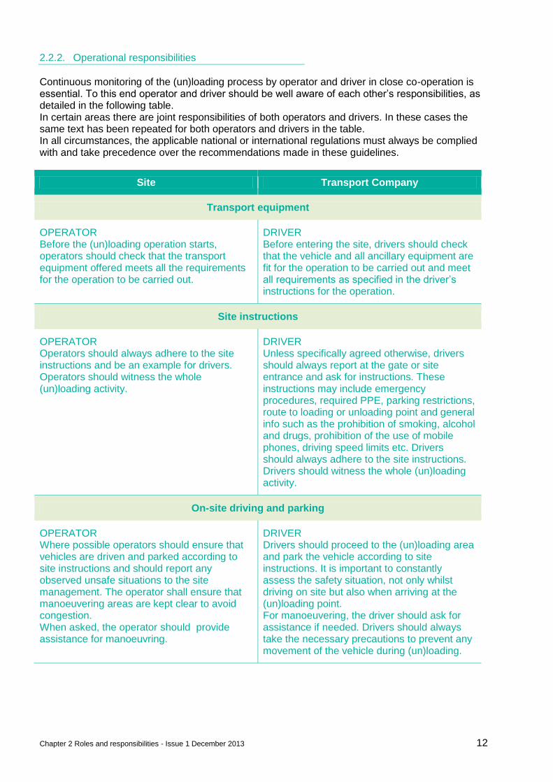
2.2.2. Operational responsibilities
Continuous monitoring of the (un)loading process by operator and driver in close co-operation is essential. To this end operator and driver should be well aware of each other’s responsibilities, as detailed in the following table. In certain areas there are joint responsibilities of both operators and drivers. In these cases the same text has been repeated for both operators and drivers in the table. In all circumstances, the applicable national or international regulations must always be complied with and take precedence over the recommendations made in these guidelines.
Site Transport Company
Transport equipment
OPERATOR Before the (un)loading operation starts, operators should check that the transport equipment offered meets all the requirements for the operation to be carried out.
DRIVER Before entering the site, drivers should check that the vehicle and all ancillary equipment are fit for the operation to be carried out and meet all requirements as specified in the driver’s instructions for the operation.
Site instructions
OPERATOR Operators should always adhere to the site instructions and be an example for drivers. Operators should witness the whole (un)loading activity.
DRIVER Unless specifically agreed otherwise, drivers should always report at the gate or site entrance and ask for instructions. These instructions may include emergency procedures, required PPE, parking restrictions, route to loading or unloading point and general info such as the prohibition of smoking, alcohol and drugs, prohibition of the use of mobile phones, driving speed limits etc. Drivers should always adhere to the site instructions. Drivers should witness the whole (un)loading activity.
On-site driving and parking
OPERATOR Where possible operators should ensure that vehicles are driven and parked according to site instructions and should report any observed unsafe situations to the site management. The operator shall ensure that manoeuvering areas are kept clear to avoid congestion. When asked, the operator should provide assistance for manoeuvring.
DRIVER Drivers should proceed to the (un)loading area and park the vehicle according to site instructions. It is important to constantly assess the safety situation, not only whilst driving on site but also when arriving at the (un)loading point. For manoeuvering, the driver should ask for assistance if needed. Drivers should always take the necessary precautions to prevent any movement of the vehicle during (un)loading.
Chapter 2 Roles and responsibilities - Issue 1 December 2013 13
Site Transport Company
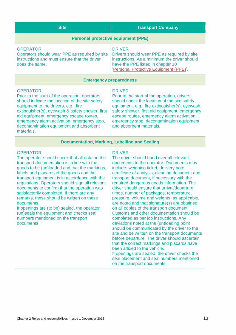
Personal protective equipment (PPE)
OPERATOR Operators should wear PPE as required by site instructions and must ensure that the driver does the same.
DRIVER Drivers should wear PPE as required by site instructions. As a minimum the driver should have the PPE listed in chapter 10 ‘Personal Protective Equipment (PPE)’.
Emergency preparedness
OPERATOR Prior to the start of the operation, operators should indicate the location of the site safety equipment to the drivers, e.g.: fire extinguisher(s), eyewash & safety shower, first aid equipment, emergency escape routes, emergency alarm activation, emergency stop, decontamination equipment and absorbent materials.
DRIVER Prior to the start of the operation, drivers should check the location of the site safety equipment, e.g.: fire extinguisher(s), eyewash, safety shower, first aid equipment, emergency escape routes, emergency alarm activation, emergency stop, decontamination equipment and absorbent materials.
Documentation, Marking, Labelling and Sealing
OPERATOR The operator should check that all data on the transport documentation is in line with the goods to be (un)loaded and that the markings, labels and placards of the goods and the transport equipment is in accordance with the regulations. Operators should sign all relevant documents to confirm that the operation was satisfactorily completed. If there are any remarks, these should be written on these documents. If openings are (to be) sealed, the operator (un)seals the equipment and checks seal numbers mentioned on the transport documents.
DRIVER The driver should hand over all relevant documents to the operator. Documents may include: weighing ticket, delivery note, certificate of analysis, cleaning document and transport document, if necessary with the required dangerous goods information. The driver should ensure that arrival/departure times, number of packages, temperature, pressure, volume and weights, as applicable, are noted and that signature(s) are obtained on all copies of the transport document. Customs and other documentation should be completed as per job instructions. Any deviations noted at the (un)loading point should be communicated by the driver to the site and be written on the transport documents before departure. The driver should ascertain that the correct markings and placards have been affixed to the vehicle. If openings are sealed, the driver checks the seal placement and seal numbers mentioned on the transport documents.
Chapter 2 Roles and responsibilities - Issue 1 December 2013 14
Site Transport Company
Product samples
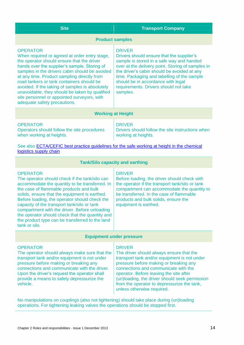
OPERATOR When required or agreed at order entry stage, the operator should ensure that the driver hands over the supplier’s sample. Storing of samples in the drivers cabin should be avoided at any time. Product sampling directly from road tankers or tank containers should be avoided. If the taking of samples is absolutely unavoidable, they should be taken by qualified site personnel or appointed surveyors, with adequate safety precautions.
DRIVER Drivers should ensure that the supplier’s sample is stored in a safe way and handed over at the delivery point. Storing of samples in the driver’s cabin should be avoided at any time. Packaging and labelling of the sample should be in accordance with legal requirements. Drivers should not take samples.
Working at Height
OPERATOR Operators should follow the site procedures when working at heights.
DRIVER Drivers should follow the site instructions when working at heights.
See also ECTA/CEFIC best practice guidelines for the safe working at height in the chemical logistics supply chain
Tank/Silo capacity and earthing
OPERATOR The operator should check if the tank/silo can accommodate the quantity to be transferred. In the case of flammable products and bulk solids, ensure that the equipment is earthed. Before loading, the operator should check the capacity of the transport tank/silo or tank compartment with the driver. Before unloading the operator should check that the quantity and the product type can be transferred to the land tank or silo.
DRIVER Before loading, the driver should check with the operator if the transport tank/silo or tank compartment can accommodate the quantity to be transferred. In the case of flammable products and bulk solids, ensure the equipment is earthed.
Equipment under pressure
OPERATOR The operator should always make sure that the transport tank and/or equipment is not under pressure before making or breaking any connections and communicate with the driver. Upon the driver’s request the operator shall provide a means to safely depressurize the vehicle.
DRIVER The driver should always ensure that the transport tank and/or equipment is not under pressure before making or breaking any connections and communicate with the operator. Before leaving the site after (un)loading, the driver should seek permission from the operator to depressurize the tank, unless otherwise required.
No manipulations on couplings (also not tightening) should take place during (un)loading operations. For tightening leaking valves the operations should be stopped first.
Chapter 2 Roles and responsibilities - Issue 1 December 2013 15
Site Transport Company
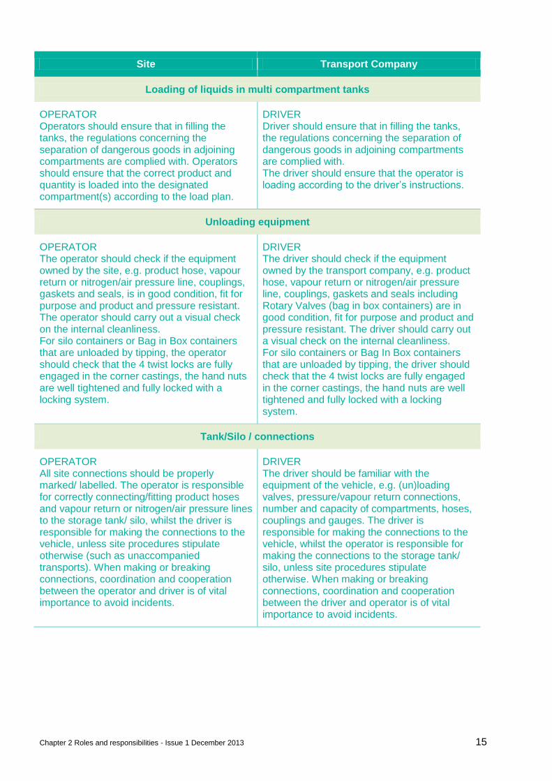
Loading of liquids in multi compartment tanks
OPERATOR Operators should ensure that in filling the tanks, the regulations concerning the separation of dangerous goods in adjoining compartments are complied with. Operators should ensure that the correct product and quantity is loaded into the designated compartment(s) according to the load plan.
DRIVER Driver should ensure that in filling the tanks, the regulations concerning the separation of dangerous goods in adjoining compartments are complied with. The driver should ensure that the operator is loading according to the driver’s instructions.
Unloading equipment
OPERATOR The operator should check if the equipment owned by the site, e.g. product hose, vapour return or nitrogen/air pressure line, couplings, gaskets and seals, is in good condition, fit for purpose and product and pressure resistant. The operator should carry out a visual check on the internal cleanliness. For silo containers or Bag in Box containers that are unloaded by tipping, the operator should check that the 4 twist locks are fully engaged in the corner castings, the hand nuts are well tightened and fully locked with a locking system.
DRIVER The driver should check if the equipment owned by the transport company, e.g. product hose, vapour return or nitrogen/air pressure line, couplings, gaskets and seals including Rotary Valves (bag in box containers) are in good condition, fit for purpose and product and pressure resistant. The driver should carry out a visual check on the internal cleanliness. For silo containers or Bag In Box containers that are unloaded by tipping, the driver should check that the 4 twist locks are fully engaged in the corner castings, the hand nuts are well tightened and fully locked with a locking system.
Tank/Silo / connections
OPERATOR All site connections should be properly marked/ labelled. The operator is responsible for correctly connecting/fitting product hoses and vapour return or nitrogen/air pressure lines to the storage tank/ silo, whilst the driver is responsible for making the connections to the vehicle, unless site procedures stipulate otherwise (such as unaccompanied transports). When making or breaking connections, coordination and cooperation between the operator and driver is of vital importance to avoid incidents.
DRIVER The driver should be familiar with the equipment of the vehicle, e.g. (un)loading valves, pressure/vapour return connections, number and capacity of compartments, hoses, couplings and gauges. The driver is responsible for making the connections to the vehicle, whilst the operator is responsible for making the connections to the storage tank/ silo, unless site procedures stipulate otherwise. When making or breaking connections, coordination and cooperation between the driver and operator is of vital importance to avoid incidents.
Chapter 2 Roles and responsibilities - Issue 1 December 2013 16
Site Transport Company
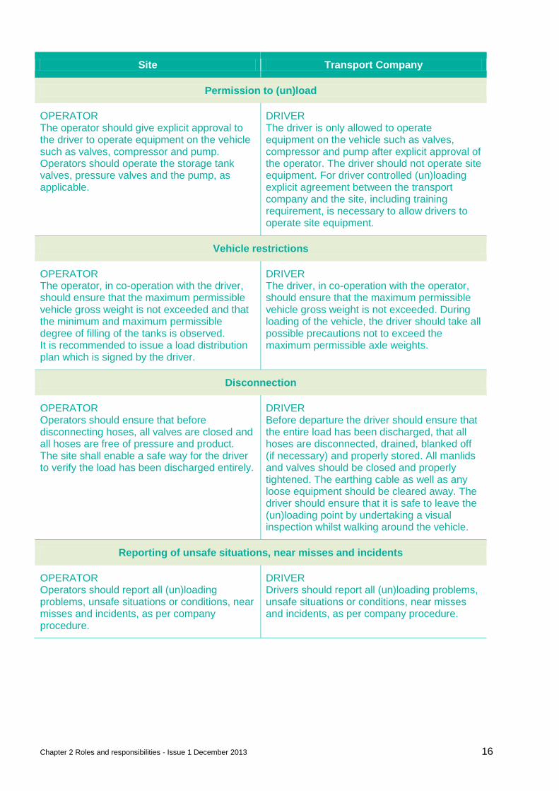
Permission to (un)load
OPERATOR The operator should give explicit approval to the driver to operate equipment on the vehicle such as valves, compressor and pump. Operators should operate the storage tank valves, pressure valves and the pump, as applicable.
DRIVER The driver is only allowed to operate equipment on the vehicle such as valves, compressor and pump after explicit approval of the operator. The driver should not operate site equipment. For driver controlled (un)loading explicit agreement between the transport company and the site, including training requirement, is necessary to allow drivers to operate site equipment.
Vehicle restrictions
OPERATOR The operator, in co-operation with the driver, should ensure that the maximum permissible vehicle gross weight is not exceeded and that the minimum and maximum permissible degree of filling of the tanks is observed. It is recommended to issue a load distribution plan which is signed by the driver.
DRIVER The driver, in co-operation with the operator, should ensure that the maximum permissible vehicle gross weight is not exceeded. During loading of the vehicle, the driver should take all possible precautions not to exceed the maximum permissible axle weights.
Disconnection
OPERATOR Operators should ensure that before disconnecting hoses, all valves are closed and all hoses are free of pressure and product. The site shall enable a safe way for the driver to verify the load has been discharged entirely.
DRIVER Before departure the driver should ensure that the entire load has been discharged, that all hoses are disconnected, drained, blanked off (if necessary) and properly stored. All manlids and valves should be closed and properly tightened. The earthing cable as well as any loose equipment should be cleared away. The driver should ensure that it is safe to leave the (un)loading point by undertaking a visual inspection whilst walking around the vehicle.
Reporting of unsafe situations, near misses and incidents
OPERATOR Operators should report all (un)loading problems, unsafe situations or conditions, near misses and incidents, as per company procedure.
DRIVER Drivers should report all (un)loading problems, unsafe situations or conditions, near misses and incidents, as per company procedure.
Chapter 2 Roles and responsibilities - Issue 1 December 2013 17
Site Transport Company
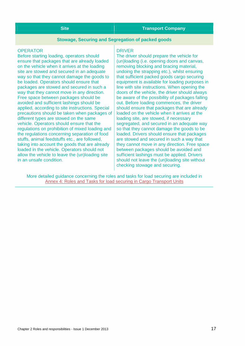
Stowage, Securing and Segregation of packed goods
OPERATOR Before starting loading, operators should ensure that packages that are already loaded on the vehicle when it arrives at the loading site are stowed and secured in an adequate way so that they cannot damage the goods to be loaded. Operators should ensure that packages are stowed and secured in such a way that they cannot move in any direction. Free space between packages should be avoided and sufficient lashings should be applied, according to site instructions. Special precautions should be taken when packages of different types are stowed on the same vehicle. Operators should ensure that the regulations on prohibition of mixed loading and the regulations concerning separation of food stuffs, animal feedstuffs etc., are followed, taking into account the goods that are already loaded in the vehicle. Operators should not allow the vehicle to leave the (un)loading site in an unsafe condition.
DRIVER The driver should prepare the vehicle for (un)loading (i.e. opening doors and canvas, removing blocking and bracing material, undoing the strapping etc.), whilst ensuring that sufficient packed goods cargo securing equipment is available for loading purposes in line with site instructions. When opening the doors of the vehicle, the driver should always be aware of the possibility of packages falling out. Before loading commences, the driver should ensure that packages that are already loaded on the vehicle when it arrives at the loading site, are stowed, if necessary segregated, and secured in an adequate way so that they cannot damage the goods to be loaded. Drivers should ensure that packages are stowed and secured in such a way that they cannot move in any direction. Free space between packages should be avoided and sufficient lashings must be applied. Drivers should not leave the (un)loading site without checking stowage and securing.
More detailed guidance concerning the roles and tasks for load securing are included in Annex 4: Roles and Tasks for load securing in Cargo Transport Units
Chapter 3 SQAS and ESAD - Issue 1 - December 2013 18
3. SQAS and ESAD
Part of the responsibilities of the organisation is to assess the risks of its supply chain as described throughout this document. When the supply chain comprises contracted road transportation, rail transportation, warehousing or tank-cleaning, the on-site risk assessment described in this guideline should be complemented by a system to qualify and periodically review transport companies, distributors and third-party providers based on Responsible Care or other health, safety, security and environmental performance criteria.
One possible way to accomplish this is through SQAS and ESAD. The SQAS and ESAD schemes consist of a team of accredited assessors that visit and assess each Logistics Service Provider or distributor using a uniform questionnaire. Those questionnaires are freely available in multiple languages on www.sqas.org.
The company will go through the questionnaire once to select the questions relevant to its business and can – provided the company subscribed to the SQAS Service Group – download reports of assessed logistic suppliers and distributors and apply the selection (called a ‘template’) to the reports, thus avoid having to spend time with each LSP or distributor covering what are actually standard industry requirements. Likewise it saves the LSP or distributor time covering the same industry audits with each customer. The saved time can thus be spent discussing what gaps are identified through this process and what, if any specific business requirements are not covered in SQAS. The effort serves the LSP or distributor as a risk assessment tool for his own operations and provides him with a reference of industry guidelines, benchmark and internal auditing all in one assessment.
Chapter 4 Emergency response plan - Issue 1 - December 2013 19
4. Emergency response plan
The on-site emergency plan should address procedures for dealing with emergency situations involving loss of containment, fire, explosion etc. It should include:
Containing and controlling incidents so as to minimize the effects and to limit danger to persons, the environment and property;
Implementing the measures necessary to protect persons and the environment;
Description of the actions which should be taken to control the conditions at events and to limit their consequences, including a description of the safety equipment and resources available;
Arrangements for training staff in the duties they will be expected to perform;
Arrangements for informing on-site personnel, local authorities and emergency services, drivers and visitors.
The emergency plan should be simple and straightforward, flexible and achieve necessary compliance with legislative requirements. Furthermore separate on-site and off-site emergency plans should be prepared.
4.1. Emergency operating procedures / training
The emergency procedures should include instructions for dealing with fires, leaks and spills. The procedure should describe how to:
Raise the alarm and call the fire brigade;
Tackle a fire or control spills and leaks (when it is safe to do so);
Evacuate the site, and if necessary nearby premises.
4.2. Area evacuation
Evacuation of areas in the event of fire or toxic gas emission should be addressed in an emergency evacuation procedure. This should specify designated safe areas, assembly points and toxic gas shelters. The procedure should also identify responsible personnel whose duties during area evacuation include:
Responsibility for a specific area;
Collecting ID badges
Communication of missing persons to central emergency services.
4.3. Fire fighting
A fire fighting strategy should consider:
Appointment of fire fighters, with subsequent training;
Location plans of fire hoses, extinguishers and water sources;
Access for emergency services;
Provision of firewater .
Chapter 4 Emergency response plan - Issue 1 - December 2013 20
4.4. Removal of substance to a safe place
The emergency spill control procedure should include the following key sections:
Spills involving hazardous materials should first be contained to prevent spread of the material to other areas. This may involve the use of temporary diking, sand bags, dry sand, earth or proprietary booms / absorbent pads;
Wherever possible the material should be rendered safe by treating with appropriate chemicals
Treated material should be absorbed onto inert carrier material to allow the material to be cleared up and removed to a safe place for disposal or further treatment in accordance with legislation.
4.5. Stabilisation / dilution to safe condition
Once the hazardous material has been contained to prevent spread of the material to other areas, the material should be treated wherever possible to render it safe. Acids and alkalis may be treated with appropriate neutralising agents. Due to the differing properties of the various groups of chemical, an appropriate treatment strategy with suitable chemicals should be established in each case. For example, highly concentrated hydrochloric acid will fume when spilled so prior to neutralization the spill should be diluted with a water spray. Once the material has been treated the area should be washed with large volumes of water. Most chemical plants and associated areas are serviced by chemical drains that feed to the effluent treatment plant. The washing operation will represent an abnormal loading on the effluent treatment plant, and it is vital that in any situation where this is likely to happen the staff responsible for operation of the effluent treatment plant are notified so that appropriate measures can be adopted.
4.6. Availability of neutralizing substances / foam
Process specific emergency spill kits (acid, alkali, solvent, toxic etc.) and appropriate personal protective equipment should be readily available with supporting procedures. These spill kits should be maintained on a regular basis to ensure that they are always available and fit for purpose. This ensures that the most appropriate measure is on hand to deal with a spill or fire in the most effective way.
Chapter 5 Applicable legislation - Issue 1 - December 2013 21
5. Applicable legislation
This section gives a generic overview of applicable legislation. Different companies are involved in (un)loading of chemicals. This could be the
chemical plant
terminal
warehouse
transport company. All have to deal with applicable legislation. The legislation can be divided into different parts:
Health and safety
Process safety
Environment
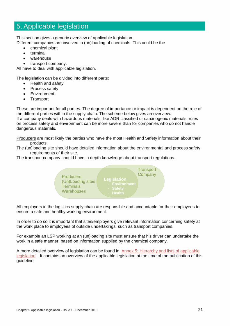
Transport These are important for all parties. The degree of importance or impact is dependent on the role of the different parties within the supply chain. The scheme below gives an overview. If a company deals with hazardous materials, like ADR classified or carcinogenic materials, rules on process safety and environment can be more severe than for companies who do not handle dangerous materials. Producers are most likely the parties who have the most Health and Safety information about their
products. The (un)loading site should have detailed information about the environmental and process safety
requirements of their site. The transport company should have in depth knowledge about transport regulations.
All employers in the logistics supply chain are responsible and accountable for their employees to ensure a safe and healthy working environment. In order to do so it is important that sites/employers give relevant information concerning safety at the work place to employees of outside undertakings, such as transport companies. For example an LSP working at an (un)loading site must ensure that his driver can undertake the work in a safe manner, based on information supplied by the chemical company. A more detailed overview of legislation can be found in ‘Annex 5: Hierarchy and lists of applicable legislation’ . It contains an overview of the applicable legislation at the time of the publication of this guideline.
Producers (Un)Loading sites Terminals Warehouses
Transport Company
Legislation - Environment - Safety
- Health
Chapter 6 Communication skills of drivers and operators - Issue 1 - December 2013 22
6. Communication skills of drivers and operators
Communication at (un)loading sites is one of the most common sources for discussion and unsafe actions during (un)loading. Therefore, ensuring that communication between drivers and operators can be made in an understandable way for both parties is key for success. This involves making sure that the (un)loading sites make their general instructions clearly understandable, preferably by making use of pictures instead of words. For assuring that drivers and operators understand each other when communicating during the (un)loading process a common language has to be found. For international transport, drivers and operators often do not share a common language. Both drivers and operators should be familiar with a fixed set of the most common expressions in a shared language. A set of 142 expressions in English is the platform of choice for this. Both transport companies and (un)loading locations should make sure that their drivers/operators have knowledge and can make use of at least the fixed set of expressions in English. The expressions required to be known by both drivers and operators are the ones defined in Transperanto (www.transperanto.org). The number of expressions required is dependent on the specific work area in which the drivers and operators are active in (e.g. packed, bulk liquid, ADR) and is a subset of 142 expressions. See also Annex 8: (Un)loading expressions / list in English Many of these expressions are also conveyed by pictograms see: www.transperanto.org Transport companies and (un)loading sites should ensure that their drivers and operators obtain the required skills. This can also involve the development of supporting means (e.g. leaflets, apps, handbooks). Rather than instructing by elaborate sentences, pictures or pictograms can be used. Some examples can be found in Annex 9: Examples of pictographic loading instructions Directive 2003/59/EC obliges professional drivers to undergo periodic retraining in the skills essential for their profession. This obligation is intended to improve road safety and the safety of the driver, including during operations carried out by the driver while the vehicle is stopped. Furthermore, the modern nature of the profession of driver should arouse young people's interest in the profession, contributing to the recruitment of new drivers at a time of shortage. One of the objectives that this Directive is trying to reach is the ability to adopt behaviour to help enhance the image of the company (Objective 3.6).
Chapter 7 Technical requirements (un)loading sites - Issue 1 - December 2013 23
Part B: Technical aspects
The following chapters of the ‘Best Practice Guideline’ list a number of standardisations and technical requirements that will improve the safety and sustainability of the chemical supply chain by reducing the interface mismatches. These include standardisation of driver PPE (Personal Protective Equipment), couplings and hoses, communication and information tools such as SULID.
7. Technical requirements (un)loading sites
‘Annex 7: Examples of Risks and Risk mitigation for (un)loading operations’ gives a brief overview of possible technical measures that can be taken to mitigate the risks that can occur at an (un)loading place. Examples of risks can be:
overflow
over pressure
under pressure
exposure to product
exposure to vapours
fire/explosion
chemical reactions
unwanted movement of vehicles
fall from vehicle
high temperatures of product An example of specific risks and requirements for safety on bulk solid unloading sites can be found in Annex 1: Example Risk assessment for Bulk Solids Unloading sites It is the responsibility of the (un)loading sites to assess the risks of (un)loading operations and to determine the measures to be taken. They are dependent on the potential effect of the failure as well as the probability. The risk can be product related, e.g. the effects of an overflow of a tank will be much more severe for a tank containing toxic material than for one containing water. Also the quantity of the product involved can play a role in the potential effect. Examples of risk tables of products, split into different groups, to illustrate the potential different risks and measures can be found in ‘Annex 7: Examples of Risks and Risk mitigation for (un)loading operations’ along with some non-standard operations which – unless specifically agreed between the parties – should be eliminated from the supply chain. Access and egress of trucks to and from the site needs to be considered
Separation of truck traffic and pedestrians
Truck manoeuvering, including the need to back up a vehicle See Annex 2: Pictorial examples of Access/ Egress to the (un)loading area for some pictorial examples. Accessibility of the site through public roads should consider roundabouts, bridges and crossings. Routing instructions can be communicated through SULID: Site (Un)Loading Information Document
Chapter 8 SULID: Site (Un)Loading Information Document - Issue 1 – December 2013 24
8. SULID: Site (Un)Loading Information Document
8.1. Legislation
Article 10 of Directive 89/391/EC states: Every employer shall take appropriate measures so that employers of workers from any outside undertakings and/or establishments engaged in work in his undertaking and/or establishment receive, in accordance with national laws and/or practices, adequate information concerning: a) the safety and health risks and protective and preventive measures and activities in respect
of both the undertaking and/or establishment in general and each type of workstation and/or job;
(b) the measures taken for the points referred to in paragraph a. Each member country has integrated this directive in national legislation. To comply with this legislation every (un)loading site should inform the management of each haulier that could be present on their site. The implementation of the above differs from country to country and from (un)loading point to (un)loading point. In France it is usual that a ‘Protocol de sécurité’ is sent to the suppliers who then distribute this information further to the potential hauliers to be evaluated and signed (every year). This protocol differs from a single information leaflet to a ten page risk assessment document. This way of working takes a lot of time and effort with limited added value. In other countries / companies the situation is variable and differs from no information at all, to entrance gate info for the driver to a full package addressed to the management of the haulier. Most of the information that is offered has been drawn up by the management of the (un)loading company without any independent or suppliers verification. Some suppliers perform an audit for (primarily) High Consequence Dangerous Goods (HCDG) prior to the first delivery but this information is rarely shared with the hauliers.
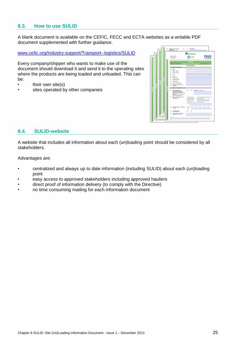
8.2. SULID-template
The ‘Site (Un)Loading Information Document’ has been created in 2011 in cooperation between CEFIC, ECTA and FECC. SULID is available in four languages. It lists all practical (technical and safety related) information about the (un)loading point in combination with the protective and preventive measures, submitted by the (un)loading site. SULID doesn’t include a risk assessment but is an excellent starting point to identify the (potential) risks and gives a clear picture of the existing situation. SULID is available for three different types of (un)loading sites depending on the nature of the products to be handled: • Bulk liquids • Bulk solids • Packed goods SULID is mainly an information document and doesn’t provide an evaluation nor a classification of the different (un)loading sites.
Chapter 8 SULID: Site (Un)Loading Information Document - Issue 1 – December 2013 25
8.3. How to use SULID
A blank document is available on the CEFIC, FECC and ECTA websites as a writable PDF document supplemented with further guidance. www.cefic.org/Industry-support/Transport--logistics/SULID Every company/shipper who wants to make use of the document should download it and send it to the operating sites where the products are being loaded and unloaded. This can be: • their own site(s) • sites operated by other companies
8.4. SULID-website
A website that includes all information about each (un)loading point should be considered by all stakeholders. Advantages are: • centralized and always up to date information (including SULID) about each (un)loading
point • easy access to approved stakeholders including approved hauliers • direct proof of information delivery (to comply with the Directive) • no time consuming mailing for each information document
Chapter 9 Information, instructions and training for drivers and operators - Issue 1 - December 2013 26
9. Information, instructions and training for drivers and operators
Drivers coming to (un)load on a site should be properly informed of the site safety requirements, route to take, (un)loading method, product hazards etc. See ‘SULID: Site (Un)Loading Information Document’ for the best practice format. Listed below are contents for information, instructions and training for drivers and operators at (un)loading sites. The (un)loading sites should use those elements which are relevant for their operators. Relevancy depends on factors like the presence of hazards or the degree of coaching, guidance and assistance of site personnel.
9.1. General information and instructions for drivers and operators
Following items are common information and instructions for both driver and operators and should be incorporated in both the driver’s and the operator’s training programs.
9.1.1. Loading/ unloading instructions
Loading/ unloading method Unloading scenario’s bulk liquid
Maximum pressure
Use of vapour return
Forklift segregation rules
Load securing requirements see also Annex 4: Roles and Tasks for load securing in Cargo Transport Units
9.1.2. Emergencies and Alarms
See also Emergency response plan
What kind of alarms (warnings/standby, fire alarms, gas alarms, tests)
Who can raise/activate an alarm
When to raise/activate an alarm
How to raise/activate an alarm (phone numbers, buttons)
What actions to take in case of alarm o Site plan with destination location, evacuation routes, assembly points o Different action pending on the kind of alarm o When (un)loading o What about truck and keys o Other attention items o After the signal of situation safe has been given
9.1.3. Health and environment
Be informed about the health and environmental hazards of the products in/on the truck.
Know the ADR hazard signage and pictograms.
Use the appropriate PPE. See also Personal Protective Equipment (PPE)
Act accordingly in case of exposure to product.
Deal with waste or spills.
Highlight and report issues, unusual events, incidents promptly.
9.1.4. Reporting of injuries, incidents, -unusual events and environmental complaints
Instructions about reporting What: injuries, environmental incidents, near misses, safety observations
Chapter 9 Information, instructions and training for drivers and operators - Issue 1 - December 2013 27
When: promptly, timely How: verbal, written, phone To whom: site personnel, drivers own organization
9.1.5. Communication formats
Listed below are formats to communicate and train (un)loading site information and instruction to drivers. Adequate signage and safety instructions at the entry to the site and the (un)loading area are considered as a minimum requirement. The (un)loading site should consider adding a combination of formats mentioned below.
Display signs, placards, posters o Traffic rules and road marks o Prohibition and obligation signs at the entrance for general site rules and specific
signs at the (un)loading area o Incident/accident equipment locations and instructions (important at the (un)loading
area) First aid kit First aid intervention contacts Stop button Fire fighting equipment Spill absorbent
o Emergency instructions as signs/pictograms (important at the (un)loading area) Alarm button Emergency number Escape routing Emergency shower / Eye wash station.
Coaching/monitoring at the (un)loading area as per operator/driver roles and responsibilities.
PowerPoint or video, covering selected content based on photographs/video of recognizable site situations, with spoken or written comment.
Flyer/leaflet, covering all content based on photographs of recognizable site situations depending on the site hazard severities, strengthened with written comment
Test on comprehension, not on prose-language skills.
(un)Loading permit, with main matters highlighted about emergencies/alarms, site circulation,
(un)Loading instructions
Site Safety Certificate or Safety Passport, for an experienced, regular/frequent and trained/informed driver – entry permit without extensive training
See Annex 9: Examples of pictographic loading instructions for practical examples.
9.2. Driver specific information and instructions
9.2.1. Drivers access rules
Language requirements; Communication skills of drivers and operators
Identification and required documents o ID or passport o Driver’s license o Drivers training certificates o Truck certificates (technical, cleaning document) o Product related (transport) documents
Special rules: frequent visitor, accompanied by others
Facilities (toilet, shower, catering)
9.2.2. Site circulation instructions, traffic rules, truck (un)loading preparation
Site plan with the location of the destination
Chapter 9 Information, instructions and training for drivers and operators - Issue 1 - December 2013 28
Use of access pass/badge: Should it be visible at all times or only for entry and exit.
Speed limits
Wearing of seat belt
Parking rules; Never block roads, escape routes, rail tracks, entrances or exits
No mobile phone use while driving (not even hands free !)
Specific arrangements and instructions for mixed traffic areas (pedestrians, forklifts.)
Documents available (any goods taken on site need to be accompanied with the proper documents)
Truck preparation o Engine off o Wheel chocks o Electricity off o Earthing o Support legs o Keys
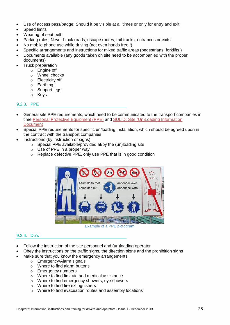
9.2.3. PPE
General site PPE requirements, which need to be communicated to the transport companies in time Personal Protective Equipment (PPE) and SULID: Site (Un)Loading Information Document
Special PPE requirements for specific un/loading installation, which should be agreed upon in the contract with the transport companies
Instructions (by instruction or signs) o Special PPE available/provided at/by the (un)loading site o Use of PPE in a proper way o Replace defective PPE, only use PPE that is in good condition
Example of a PPE pictogram
9.2.4. Do’s
Follow the instruction of the site personnel and (un)loading operator
Obey the instructions on the traffic signs, the direction signs and the prohibition signs
Make sure that you know the emergency arrangements: o Emergency/Alarm signals o Where to find alarm buttons o Emergency numbers o Where to find first aid and medical assistance o Where to find emergency showers, eye showers o Where to find fire extinguishers o Where to find evacuation routes and assembly locations
Chapter 9 Information, instructions and training for drivers and operators - Issue 1 - December 2013 29
9.2.5. Don’ts
No alcohol and/or drugs
No use of camera’s
No ignition sources: o No fire/lighters/matches o No smoking o No mobile phone use
No climbing on trucks (working at heights) without fall protection
No plant equipment use without permission
No entry of blocked premises or roads
No eating and drinking (can be different per (un)loading site)
9.2.6. Product specific training
For products with severe hazards (flammables, health hazards) loaders/shippers may choose to develop/provide training and information about:
Product characteristics
Specific PPE
Handling requirements o Loading key safety requirements o Delivery/unloading key safety requirements
What to do in case of an undesirable event (accidental contact, accidental release, runaway reaction, fire)
Reporting of near misses and/or undesirable events
Suggested formats
Classroom ‘train the trainer’ or training
Leaflet, checklist with coaching on how to use equipment
9.3. Operator specific information and instructions
All operators working at production plants and other (un)loading sites should have been trained according to the legal standards required for their type of work. Besides the legal requirements the company should provide operators with Plant/(un)loading Operating Procedures that are trained and explained by an experienced operator. In an activity based program all operators should gain theoretical knowledge of the plants and (un)loading facilities. When finalizing the theoretical knowledge training they should be tested by an experienced technician/operator. These tests are planned for the operator via a training scheme with repetition of key elements to reinforce the learning. Operators working at (un)loading installations necessarily work with outside partners in an area where behaviour is of paramount importance. Each of the chapters in Part A: Organizational and Behavioural Aspects should be integral part of the training program.
Chapter 10 Personal Protective Equipment (PPE) - Issue 1 - December 2013 30
10. Personal Protective Equipment (PPE)
This chapter focuses on Personal Protective Equipment (PPE) as the last barrier of defence to protect the driver against risks during (un)loading activities in a chemical plant environment. The required PPE for site access are complementary to the requirements of ADR for PPE for the risks during driving and in case of accidents or emergencies during transport. This chapter covers only general PPE requirements that are applicable for general chemical products of ‘most’ sites. For specific products (e.g. class 8 or 6.1) and/or for specific chemical plant environments, additional specific PPE may be required in accordance with the relevant SDS and risk assessments. These additional PPE requirements are not included in the present document and should be communicated to the transport company with sufficient notice ref:’SULID: Site (Un)Loading Information Document’ or should be made available by the chemical plant.
10.1. Risk Analysis
Personal Protective Equipment (PPE) requirements for site access of contractors, including drivers, are defined based on a risk analysis of the task to be performed and the environment in which the task is performed. See ‘Management responsibilities’ for guidance on risk assessment. As products, tasks and environments differ from plant to plant the PPE requirements for contractors will be equally different. Drivers make a unique exception to this differentiation as drivers usually visit and work on several locations. When sites prescribe PPE at a lower level of protection as detailed in this chapter, it is recommendable that site management performs a task specific risk review to confirm the adequateness of the level of protection of the PPE. When sites prescribe PPE at a higher level of protection than the PPE guidance provided in this chapter, it is recommendable that the management of the transport company together with the site management perform a joint task specific risk review to confirm this requirement for such higher level of protection. Wearing PPE may introduce additional risks. The risk analysis should include such considerations.
Safety glasses may limit or hinder sight.
Ear protection hinders verbal communication.
Safety gloves will limit the capabilities of the hands: fine motor control, tactile sense…
Safety shoe with rigid or steel sole decrease the sensitivity of the driver to the pedal. As safety shoes are usually mandatory on-site even inside the cab these are not recommended. High laced shoes (for ankle-protecting) have an additional protection but can be uncomfortable for driving.
Chapter 10 Personal Protective Equipment (PPE) - Issue 1 - December 2013 31
10.2. 3 different sets of PPE
Drivers can conduct 3 different types of (un)loading operations. Therefore 3 different sets of PPE should be used dependent on the type of chemical products that are being transported and handled.
10.2.1. Type 1: packed goods and drop-and-swap
Drivers (un)loading sealed packed goods and drivers carrying out drop and swap operations (i.e. dropping off or taking on a trailer/container at/from a chemical or storage facility without performing product (un)loading activities). These drivers access chemical sites but are not likely to be exposed to chemicals. Equally they are not likely to have to engage in working at height nor do their tasks usually involve risk of flammable atmospheres.
10.2.2. Type 2: bulk granulates
Drivers (un)loading bulk granulates or solid chemicals without danger classification access chemical sites but are not likely to be exposed to chemicals as such. But they often engage in working at height. Their tasks and environment do not usually involve risk of flammable atmospheres.
10.2.3. Type 3: bulk liquids and DG solids
Drivers (un)loading bulk liquids (ADR and non-ADR) and classified solids (ADR) access chemical sites and work in areas where the likelihood of being exposed to chemicals they carry or chemicals already present in vessels or lines can’t be ignored. Equally they often have to engage in working at height and their tasks might involve risk of flammable atmospheres if those are present at or near to the (un)loading location (not limited to those arising from the product they transport).
10.3. Sets of required PPE for different types of (un)loading operations
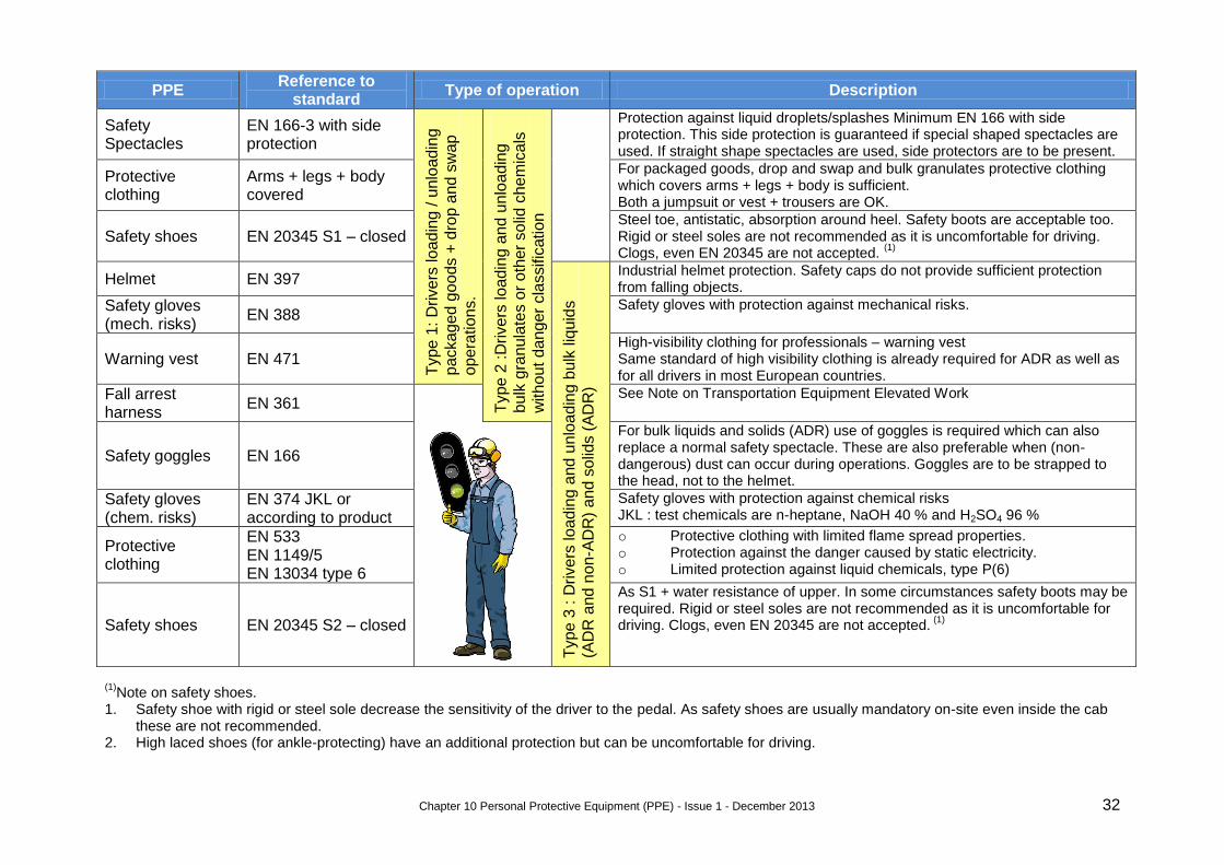
The selection of the sets of PPE is based on the risks of these types of products and the risks related to the activities in a chemical plant environment, which are not necessarily limited to the loaded/unloaded product. These sets of equipment should be available to the driver at all times. Most of the equipment has to be worn while working on any chemical site. Specific items such as the fall arrest harness and hearing protection are used in specific circumstances. The chemical site will agree with the driver upon these circumstances. Listed below are PPE by type as described above in relation to the applicable standards and some additional clarification. Where multiple norms apply, the item needs to comply with each norm listed. The required PPE should be used properly, kept in good condition and the drivers are to be adequately trained to use them.
Chapter 10 Personal Protective Equipment (PPE) - Issue 1 - December 2013 32
PPE Reference to
standard Type of operation Description
Safety Spectacles
EN 166-3 with side protection
Type
1: D
rive
rs lo
ad
ing / u
nlo
ad
ing
packa
ge
d g
oo
ds +
dro
p a
nd
sw
ap
ope
ratio
ns.
Type
2 :D
rive
rs lo
ad
ing a
nd u
nlo
ad
ing
bulk
gra
nu
late
s o
r o
ther
so
lid c
he
mic
als
with
ou
t d
an
ger
cla
ssific
atio
n
Protection against liquid droplets/splashes Minimum EN 166 with side protection. This side protection is guaranteed if special shaped spectacles are used. If straight shape spectacles are used, side protectors are to be present.
Protective clothing
Arms + legs + body covered
For packaged goods, drop and swap and bulk granulates protective clothing which covers arms + legs + body is sufficient. Both a jumpsuit or vest + trousers are OK.
Safety shoes EN 20345 S1 – closed Steel toe, antistatic, absorption around heel. Safety boots are acceptable too. Rigid or steel soles are not recommended as it is uncomfortable for driving. Clogs, even EN 20345 are not accepted.
(1)
Helmet EN 397
Type
3 : D
rive
rs lo
ad
ing a
nd
un
load
ing b
ulk
liq
uid
s
(AD
R a
nd
no
n-A
DR
) a
nd s
olid
s (
AD
R)
Industrial helmet protection. Safety caps do not provide sufficient protection from falling objects.
Safety gloves (mech. risks)
EN 388 Safety gloves with protection against mechanical risks.
Warning vest EN 471 High-visibility clothing for professionals – warning vest Same standard of high visibility clothing is already required for ADR as well as for all drivers in most European countries.
Fall arrest harness
EN 361 See Note on Transportation Equipment Elevated Work
Safety goggles EN 166
For bulk liquids and solids (ADR) use of goggles is required which can also replace a normal safety spectacle. These are also preferable when (non-dangerous) dust can occur during operations. Goggles are to be strapped to the head, not to the helmet.
Safety gloves (chem. risks)
EN 374 JKL or according to product
Safety gloves with protection against chemical risks JKL : test chemicals are n-heptane, NaOH 40 % and H2SO4 96 %
Protective clothing
EN 533 EN 1149/5 EN 13034 type 6
o Protective clothing with limited flame spread properties. o Protection against the danger caused by static electricity. o Limited protection against liquid chemicals, type P(6)
Safety shoes EN 20345 S2 – closed
As S1 + water resistance of upper. In some circumstances safety boots may be required. Rigid or steel soles are not recommended as it is uncomfortable for driving. Clogs, even EN 20345 are not accepted.
(1)
(1)Note on safety shoes.
1. Safety shoe with rigid or steel sole decrease the sensitivity of the driver to the pedal. As safety shoes are usually mandatory on-site even inside the cab these are not recommended.
2. High laced shoes (for ankle-protecting) have an additional protection but can be uncomfortable for driving.
Chapter 11 Unloading scenario’s bulk liquid - Issue 1 – December 2013 33
11. Unloading scenario’s bulk liquid
In no order of preference the 4 most common scenarios for unloading bulk liquids are: 1. Bottom unloading by pump and vapour return 2. Bottom discharge by pump without vapour return 3. Bottom unloading by compressed air or inert gas. 4. Top Discharge
For each of these scenario’s the text below describes the key characteristics, main advantages and disadvantages and conditions for safe practice. The document focuses on (un)loading operations both through the top or via the bottom of vehicles, this is commonly done with a flexible hose but an (un)loading arm can be considered too.
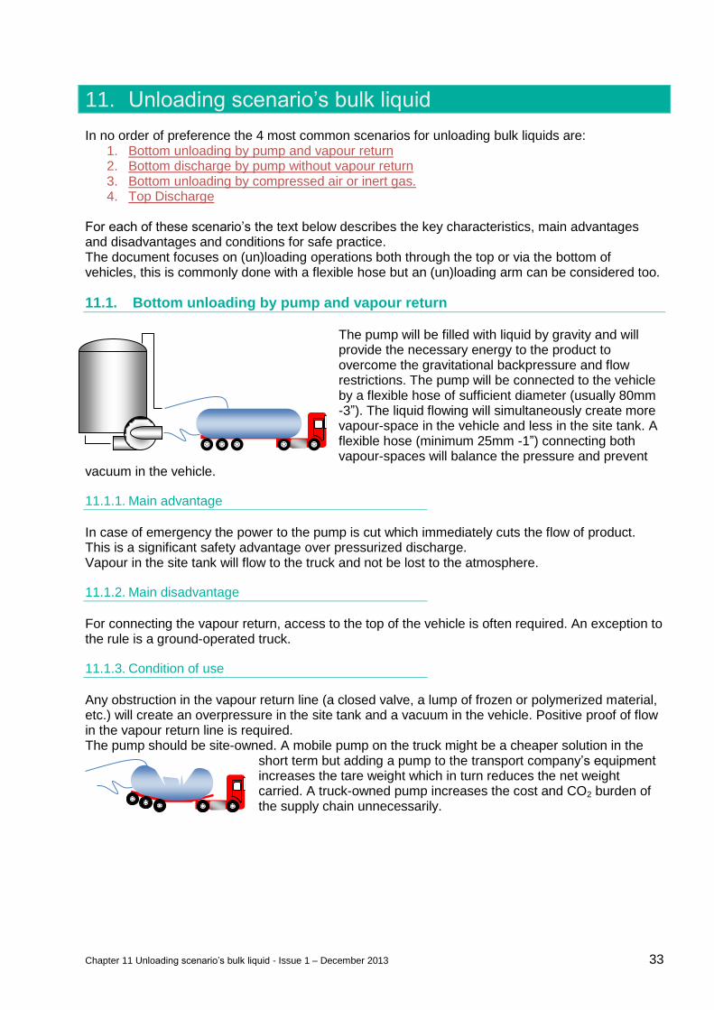
11.1. Bottom unloading by pump and vapour return
The pump will be filled with liquid by gravity and will provide the necessary energy to the product to overcome the gravitational backpressure and flow restrictions. The pump will be connected to the vehicle by a flexible hose of sufficient diameter (usually 80mm -3”). The liquid flowing will simultaneously create more vapour-space in the vehicle and less in the site tank. A flexible hose (minimum 25mm -1”) connecting both vapour-spaces will balance the pressure and prevent
vacuum in the vehicle.
11.1.1. Main advantage
In case of emergency the power to the pump is cut which immediately cuts the flow of product. This is a significant safety advantage over pressurized discharge. Vapour in the site tank will flow to the truck and not be lost to the atmosphere.
11.1.2. Main disadvantage
For connecting the vapour return, access to the top of the vehicle is often required. An exception to the rule is a ground-operated truck.
11.1.3. Condition of use
Any obstruction in the vapour return line (a closed valve, a lump of frozen or polymerized material, etc.) will create an overpressure in the site tank and a vacuum in the vehicle. Positive proof of flow in the vapour return line is required. The pump should be site-owned. A mobile pump on the truck might be a cheaper solution in the
short term but adding a pump to the transport company’s equipment increases the tare weight which in turn reduces the net weight carried. A truck-owned pump increases the cost and CO2 burden of the supply chain unnecessarily.
Chapter 11 Unloading scenario’s bulk liquid - Issue 1 – December 2013 34
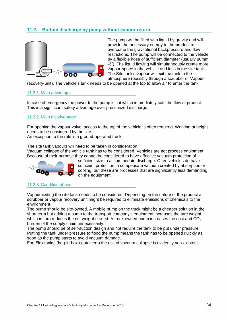
11.2. Bottom discharge by pump without vapour return
The pump will be filled with liquid by gravity and will provide the necessary energy to the product to overcome the gravitational backpressure and flow restrictions. The pump will be connected to the vehicle by a flexible hose of sufficient diameter (usually 80mm -3”). The liquid flowing will simultaneously create more vapour-space in the vehicle and less in the site tank. The Site tank’s vapour will exit the tank to the atmosphere (possibly through a scrubber or Vapour-
recovery-unit). The vehicle’s tank needs to be opened at the top to allow air to enter the tank.
11.2.1. Main advantage
In case of emergency the power to the pump is cut which immediately cuts the flow of product. This is a significant safety advantage over pressurized discharge.
11.2.2. Main disadvantage
For opening the vapour valve, access to the top of the vehicle is often required. Working at height needs to be considered by the site. An exception to the rule is a ground-operated truck. The site tank vapours will need to be taken in consideration. Vacuum collapse of the vehicle tank has to be considered. Vehicles are not process equipment. Because of their purpose they cannot be considered to have effective vacuum protection of
sufficient size to accommodate discharge. Often vehicles do have sufficient protection to compensate vacuum created by absorption or cooling, but these are processes that are significantly less demanding on the equipment.
11.2.3. Condition of use
Vapour exiting the site tank needs to be considered. Depending on the nature of the product a scrubber or vapour recovery unit might be required to eliminate emissions of chemicals to the environment. The pump should be site-owned. A mobile pump on the truck might be a cheaper solution in the short term but adding a pump to the transport company’s equipment increases the tare weight which in turn reduces the net weight carried. A truck-owned pump increases the cost and CO2 burden of the supply chain unnecessarily. The pump should be of self-suction design and not require the tank to be put under pressure. Putting the tank under pressure to flood the pump means the tank has to be opened quickly as soon as the pump starts to avoid vacuum damage. For ‘Flexitanks’ (bag-in-box-containers) the risk of vacuum collapse is evidently non-existent.
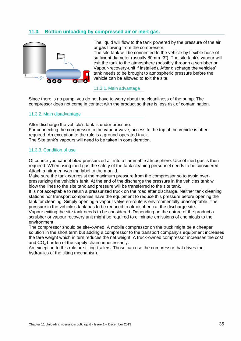
Chapter 11 Unloading scenario’s bulk liquid - Issue 1 – December 2013 35
11.3. Bottom unloading by compressed air or inert gas.
The liquid will flow to the tank powered by the pressure of the air or gas flowing from the compressor. The site tank will be connected to the vehicle by flexible hose of sufficient diameter (usually 80mm -3”). The site tank’s vapour will exit the tank to the atmosphere (possibly through a scrubber or Vapour-recovery-unit if installed). After discharge the vehicles’ tank needs to be brought to atmospheric pressure before the vehicle can be allowed to exit the site.
11.3.1. Main advantage
Since there is no pump, you do not have to worry about the cleanliness of the pump. The compressor does not come in contact with the product so there is less risk of contamination.
11.3.2. Main disadvantage
After discharge the vehicle’s tank is under pressure. For connecting the compressor to the vapour valve, access to the top of the vehicle is often required. An exception to the rule is a ground-operated truck. The Site tank’s vapours will need to be taken in consideration.
11.3.3. Condition of use
Of course you cannot blow pressurized air into a flammable atmosphere. Use of inert gas is then required. When using inert gas the safety of the tank cleaning personnel needs to be considered. Attach a nitrogen-warning label to the manlid. Make sure the tank can resist the maximum pressure from the compressor so to avoid over-pressurizing the vehicle’s tank. At the end of the discharge the pressure in the vehicles tank will blow the lines to the site tank and pressure will be transferred to the site tank. It is not acceptable to return a pressurized truck on the road after discharge. Neither tank cleaning stations nor transport companies have the equipment to reduce this pressure before opening the tank for cleaning. Simply opening a vapour valve en-route is environmentally unacceptable. The pressure in the vehicle’s tank has to be reduced to atmospheric at the discharge site. Vapour exiting the site tank needs to be considered. Depending on the nature of the product a scrubber or vapour recovery unit might be required to eliminate emissions of chemicals to the environment. The compressor should be site-owned. A mobile compressor on the truck might be a cheaper solution in the short term but adding a compressor to the transport company’s equipment increases the tare weight which in turn reduces the net weight. A truck-owned compressor increases the cost and CO2 burden of the supply chain unnecessarily. An exception to this rule are tilting-trailers. Those can use the compressor that drives the hydraulics of the tilting mechanism.
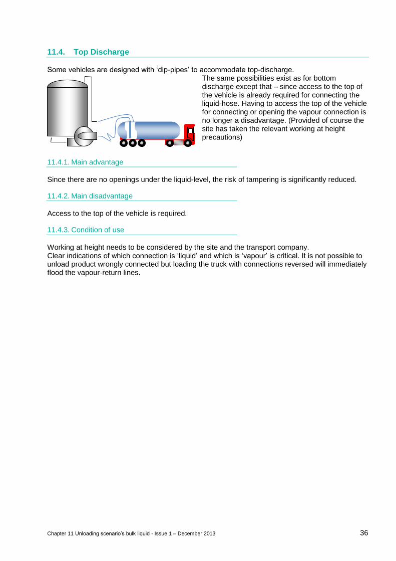
Chapter 11 Unloading scenario’s bulk liquid - Issue 1 – December 2013 36
11.4. Top Discharge
Some vehicles are designed with ‘dip-pipes’ to accommodate top-discharge. The same possibilities exist as for bottom discharge except that – since access to the top of the vehicle is already required for connecting the liquid-hose. Having to access the top of the vehicle for connecting or opening the vapour connection is no longer a disadvantage. (Provided of course the site has taken the relevant working at height precautions)
11.4.1. Main advantage
Since there are no openings under the liquid-level, the risk of tampering is significantly reduced.
11.4.2. Main disadvantage
Access to the top of the vehicle is required.
11.4.3. Condition of use
Working at height needs to be considered by the site and the transport company. Clear indications of which connection is ‘liquid’ and which is ‘vapour’ is critical. It is not possible to unload product wrongly connected but loading the truck with connections reversed will immediately flood the vapour-return lines.
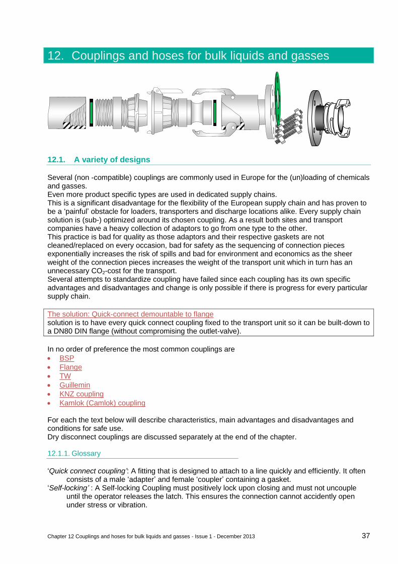
Chapter 12 Couplings and hoses for bulk liquids and gasses - Issue 1 - December 2013 37
12. Couplings and hoses for bulk liquids and gasses
12.1. A variety of designs
Several (non -compatible) couplings are commonly used in Europe for the (un)loading of chemicals and gasses. Even more product specific types are used in dedicated supply chains. This is a significant disadvantage for the flexibility of the European supply chain and has proven to be a ‘painful’ obstacle for loaders, transporters and discharge locations alike. Every supply chain solution is (sub-) optimized around its chosen coupling. As a result both sites and transport companies have a heavy collection of adaptors to go from one type to the other. This practice is bad for quality as those adaptors and their respective gaskets are not cleaned/replaced on every occasion, bad for safety as the sequencing of connection pieces exponentially increases the risk of spills and bad for environment and economics as the sheer weight of the connection pieces increases the weight of the transport unit which in turn has an unnecessary CO2-cost for the transport. Several attempts to standardize coupling have failed since each coupling has its own specific advantages and disadvantages and change is only possible if there is progress for every particular supply chain.
The solution: Quick-connect demountable to flange solution is to have every quick connect coupling fixed to the transport unit so it can be built-down to a DN80 DIN flange (without compromising the outlet-valve).
In no order of preference the most common couplings are
BSP
Flange
TW
Guillemin
KNZ coupling
Kamlok (Camlok) coupling For each the text below will describe characteristics, main advantages and disadvantages and conditions for safe use. Dry disconnect couplings are discussed separately at the end of the chapter.
12.1.1. Glossary
‘Quick connect coupling’: A fitting that is designed to attach to a line quickly and efficiently. It often consists of a male ‘adapter’ and female ‘coupler’ containing a gasket.
‘Self-locking’ : A Self-locking Coupling must positively lock upon closing and must not uncouple until the operator releases the latch. This ensures the connection cannot accidently open under stress or vibration.
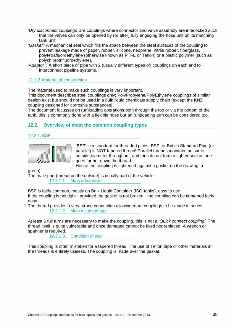
Chapter 12 Couplings and hoses for bulk liquids and gasses - Issue 1 - December 2013 38
‘Dry disconnect couplings’ are couplings where connector and valve assembly are interlocked such that the valves can only be opened by (or after) fully engaging the hose unit on its matching tank unit.
‘Gasket’: A mechanical seal which fills the space between the steel surfaces of the coupling to prevent leakage made of paper, rubber, silicone, neoprene, nitrile rubber, fiberglass, polytetrafluoroethylene (otherwise known as PTFE or Teflon) or a plastic polymer (such as polychlorotrifluoroethylene).
‘Adaptor’ : A short piece of pipe with 2 (usually different types of) couplings on each end to interconnect pipeline systems.
12.1.2. Material of construction
The material used to make such couplings is very important. This document describes steel couplings only; PolyPropylene/PolyEthylene couplings of similar design exist but should not be used in a bulk liquid chemicals supply chain (except the KNZ coupling designed for corrosive substances). The document focusses on (un)loading operations both through the top or via the bottom of the tank, this is commonly done with a flexible hose but an (un)loading arm can be considered too.
12.2. Overview of most the common coupling types
12.2.1. BSP
’BSP’ is a standard for threaded pipes. BSP, or British Standard Pipe (or parallel) is NOT tapered thread! Parallel threads maintain the same outside diameter throughout, and thus do not form a tighter seal as one goes further down the thread. Hence the coupling is tightened against a gasket (in the drawing in
green). The male part (thread on the outside) is usually part of the vehicle.
12.2.1.1. Main advantage
BSP is fairly common, mostly on Bulk Liquid Container (ISO-tanks), easy to use. If the coupling is not tight - provided the gasket is not broken - the coupling can be tightened fairly easy. The thread provides a very strong connection allowing more couplings to be made in series.
12.2.1.2. Main disadvantage
At least 6 full turns are necessary to make the coupling, this is not a ‘Quick connect coupling’. The thread itself is quite vulnerable and once damaged cannot be fixed nor replaced. A wrench or spanner is required.
12.2.1.3. Condition of use
This coupling is often mistaken for a tapered thread. The use of Teflon tape or other materials in the threads is entirely useless. The coupling is made over the gasket.
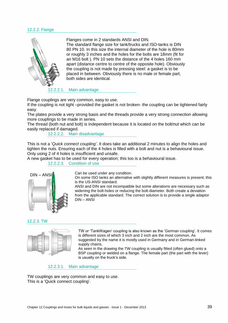
Chapter 12 Couplings and hoses for bulk liquids and gasses - Issue 1 - December 2013 39
12.2.2. Flange
Flanges come in 2 standards ANSI and DIN. The standard flange size for tank/trucks and ISO-tanks is DIN 80 PN 10. In this size the internal diameter of the hole is 80mm or roughly 3 inches and the holes for the bolts are 18mm (fit for an M16 bolt ). PN 10 sets the distance of the 4 holes 160 mm apart (distance centre to centre of the opposite hole). Obviously the coupling is not made by pressing steel: a gasket is to be placed in between. Obviously there is no male or female part, both sides are identical.
12.2.2.1. Main advantage
Flange couplings are very common, easy to use. If the coupling is not tight –provided the gasket is not broken- the coupling can be tightened fairly easy. The plates provide a very strong basis and the threads provide a very strong connection allowing more couplings to be made in series. The thread (both nut and bolt) is independent because it is located on the bolt/nut which can be easily replaced if damaged.
12.2.2.2. Main disadvantage
This is not a ‘Quick connect coupling’. It does take an additional 2 minutes to align the holes and tighten the nuts. Ensuring each of the 4 holes is filled with a bolt and nut is a behavioural issue. Only using 2 of 4 holes is insufficient and unsafe. A new gasket has to be used for every operation; this too is a behavioural issue.
12.2.2.3. Condition of use
Can be used under any condition. On some ISO tanks an alternative with slightly different measures is present; this is the US-ANSI standard. ANSI and DIN are not incompatible but some alterations are necessary such as widening the bolt-holes or reducing the bolt-diameter. Both create a deviation from the applicable standard. The correct solution is to provide a single adaptor DIN – ANSI
12.2.3. TW
TW or ‘TankWagen’ coupling is also known as the ‘German coupling’. It comes is different sizes of which 3 inch and 2 inch are the most common. As suggested by the name it is mostly used in Germany and in German-linked supply chains. As seen in the drawing the TW coupling is usually fitted (often glued) onto a BSP coupling or welded on a flange. The female part (the part with the lever) is usually on the truck’s side.
12.2.3.1. Main advantage
TW couplings are very common and easy to use. This is a ‘Quick connect coupling’.
DIN – ANSI
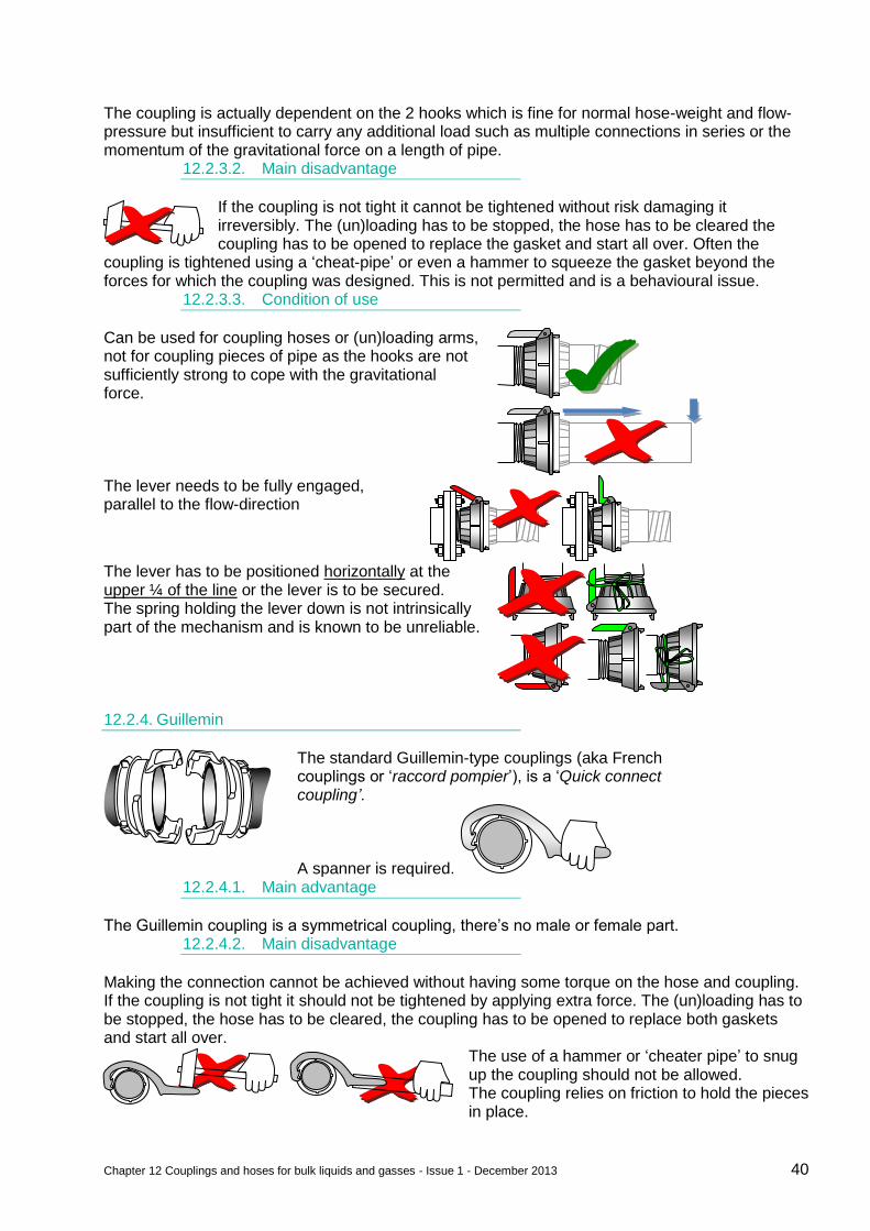
Chapter 12 Couplings and hoses for bulk liquids and gasses - Issue 1 - December 2013 40
The coupling is actually dependent on the 2 hooks which is fine for normal hose-weight and flow-pressure but insufficient to carry any additional load such as multiple connections in series or the momentum of the gravitational force on a length of pipe.
12.2.3.2. Main disadvantage
If the coupling is not tight it cannot be tightened without risk damaging it irreversibly. The (un)loading has to be stopped, the hose has to be cleared the coupling has to be opened to replace the gasket and start all over. Often the
coupling is tightened using a ‘cheat-pipe’ or even a hammer to squeeze the gasket beyond the forces for which the coupling was designed. This is not permitted and is a behavioural issue.
12.2.3.3. Condition of use
Can be used for coupling hoses or (un)loading arms, not for coupling pieces of pipe as the hooks are not sufficiently strong to cope with the gravitational force.
The lever needs to be fully engaged, parallel to the flow-direction
The lever has to be positioned horizontally at the upper ¼ of the line or the lever is to be secured. The spring holding the lever down is not intrinsically part of the mechanism and is known to be unreliable.
12.2.4. Guillemin
The standard Guillemin-type couplings (aka French couplings or ‘raccord pompier’), is a ‘Quick connect coupling’.
A spanner is required. 12.2.4.1. Main advantage
The Guillemin coupling is a symmetrical coupling, there’s no male or female part. 12.2.4.2. Main disadvantage
Making the connection cannot be achieved without having some torque on the hose and coupling. If the coupling is not tight it should not be tightened by applying extra force. The (un)loading has to be stopped, the hose has to be cleared, the coupling has to be opened to replace both gaskets and start all over.
The use of a hammer or ‘cheater pipe’ to snug up the coupling should not be allowed. The coupling relies on friction to hold the pieces in place.
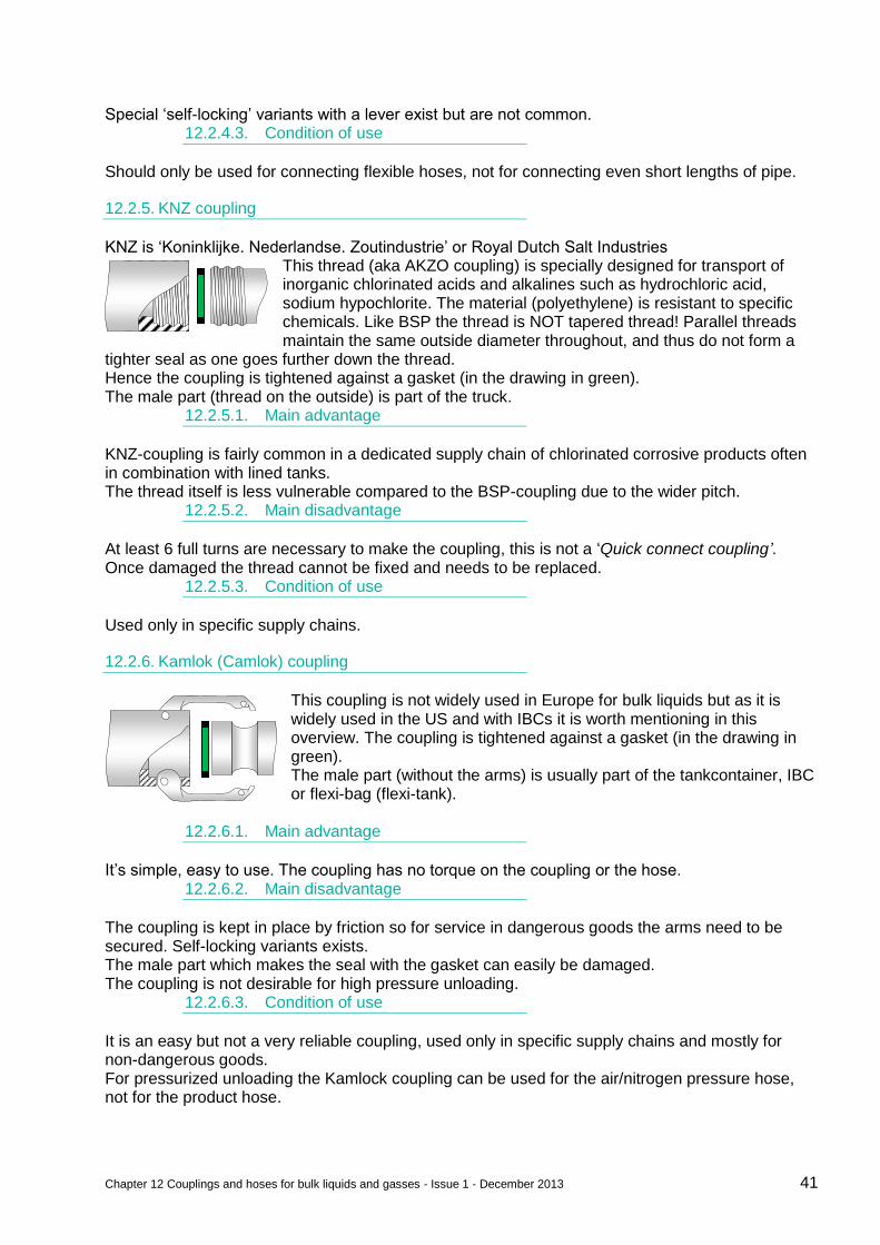
Chapter 12 Couplings and hoses for bulk liquids and gasses - Issue 1 - December 2013 41
Special ‘self-locking’ variants with a lever exist but are not common. 12.2.4.3. Condition of use
Should only be used for connecting flexible hoses, not for connecting even short lengths of pipe.
12.2.5. KNZ coupling
KNZ is ‘Koninklijke. Nederlandse. Zoutindustrie’ or Royal Dutch Salt Industries This thread (aka AKZO coupling) is specially designed for transport of inorganic chlorinated acids and alkalines such as hydrochloric acid, sodium hypochlorite. The material (polyethylene) is resistant to specific chemicals. Like BSP the thread is NOT tapered thread! Parallel threads maintain the same outside diameter throughout, and thus do not form a
tighter seal as one goes further down the thread. Hence the coupling is tightened against a gasket (in the drawing in green). The male part (thread on the outside) is part of the truck.
12.2.5.1. Main advantage
KNZ-coupling is fairly common in a dedicated supply chain of chlorinated corrosive products often in combination with lined tanks. The thread itself is less vulnerable compared to the BSP-coupling due to the wider pitch.
12.2.5.2. Main disadvantage
At least 6 full turns are necessary to make the coupling, this is not a ‘Quick connect coupling’. Once damaged the thread cannot be fixed and needs to be replaced.
12.2.5.3. Condition of use
Used only in specific supply chains.
12.2.6. Kamlok (Camlok) coupling
This coupling is not widely used in Europe for bulk liquids but as it is widely used in the US and with IBCs it is worth mentioning in this overview. The coupling is tightened against a gasket (in the drawing in green). The male part (without the arms) is usually part of the tankcontainer, IBC or flexi-bag (flexi-tank).
12.2.6.1. Main advantage
It’s simple, easy to use. The coupling has no torque on the coupling or the hose. 12.2.6.2. Main disadvantage
The coupling is kept in place by friction so for service in dangerous goods the arms need to be secured. Self-locking variants exists. The male part which makes the seal with the gasket can easily be damaged. The coupling is not desirable for high pressure unloading.
12.2.6.3. Condition of use
It is an easy but not a very reliable coupling, used only in specific supply chains and mostly for non-dangerous goods. For pressurized unloading the Kamlock coupling can be used for the air/nitrogen pressure hose, not for the product hose.
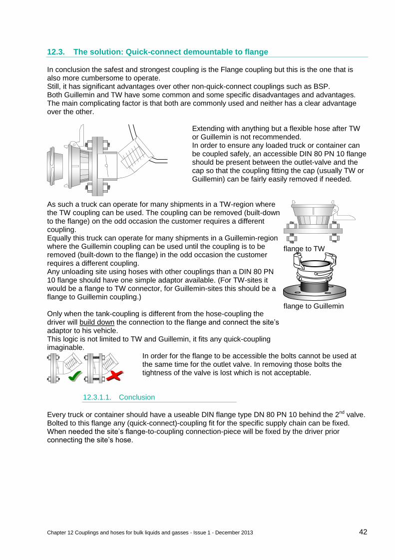
Chapter 12 Couplings and hoses for bulk liquids and gasses - Issue 1 - December 2013 42
12.3. The solution: Quick-connect demountable to flange
In conclusion the safest and strongest coupling is the Flange coupling but this is the one that is also more cumbersome to operate. Still, it has significant advantages over other non-quick-connect couplings such as BSP. Both Guillemin and TW have some common and some specific disadvantages and advantages. The main complicating factor is that both are commonly used and neither has a clear advantage over the other.
Extending with anything but a flexible hose after TW or Guillemin is not recommended. In order to ensure any loaded truck or container can be coupled safely, an accessible DIN 80 PN 10 flange should be present between the outlet-valve and the cap so that the coupling fitting the cap (usually TW or Guillemin) can be fairly easily removed if needed.
As such a truck can operate for many shipments in a TW-region where the TW coupling can be used. The coupling can be removed (built-down to the flange) on the odd occasion the customer requires a different coupling. Equally this truck can operate for many shipments in a Guillemin-region where the Guillemin coupling can be used until the coupling is to be removed (built-down to the flange) in the odd occasion the customer requires a different coupling. Any unloading site using hoses with other couplings than a DIN 80 PN 10 flange should have one simple adaptor available. (For TW-sites it would be a flange to TW connector, for Guillemin-sites this should be a flange to Guillemin coupling.) Only when the tank-coupling is different from the hose-coupling the driver will build down the connection to the flange and connect the site’s adaptor to his vehicle. This logic is not limited to TW and Guillemin, it fits any quick-coupling imaginable.
flange to TW
flange to Guillemin
In order for the flange to be accessible the bolts cannot be used at the same time for the outlet valve. In removing those bolts the tightness of the valve is lost which is not acceptable.
12.3.1.1. Conclusion
Every truck or container should have a useable DIN flange type DN 80 PN 10 behind the 2nd valve. Bolted to this flange any (quick-connect)-coupling fit for the specific supply chain can be fixed. When needed the site’s flange-to-coupling connection-piece will be fixed by the driver prior connecting the site’s hose.
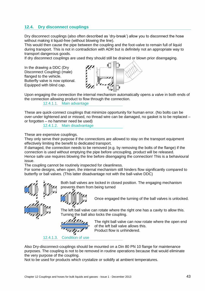
Chapter 12 Couplings and hoses for bulk liquids and gasses - Issue 1 - December 2013 43
12.4. Dry disconnect couplings
Dry disconnect couplings (also often described as ‘dry-break’) allow you to disconnect the hose without making it liquid-free (without blowing the line). This would then cause the pipe between the coupling and the foot-valve to remain full of liquid during transport. This is not in contradiction with ADR but is definitely not an appropriate way to transport dangerous goods. If dry disconnect couplings are used they should still be drained or blown prior disengaging.
In the drawing a DDC (Dry Disconnect Coupling) (male) flanged to the vehicle. Butterfly valve is now optional. Equipped with blind cap.
Upon engaging the connection the internal mechanism automatically opens a valve in both ends of the connection allowing product to flow through the connection.
12.4.1.1. Main advantage
These are quick-connect couplings that minimize opportunity for human error. (No bolts can be over-under tightened and or missed, no thread wire can be damaged, no gasket is to be replaced – or forgotten – no hammer need be used)
12.4.1.2. Main disadvantage
These are expensive couplings. They only serve their purpose if the connections are allowed to stay on the transport equipment effectively limiting the benefit to dedicated transport. If damaged, the connection needs to be removed (e.g. by removing the bolts of the flange) if the connection is used without emptying the pipe before uncoupling, product will be released. Hence safe use requires blowing the line before disengaging the connection! This is a behavioural issue. The coupling cannot be routinely inspected for cleanliness. For some designs, when open, the internal mechanism still hinders flow significantly compared to butterfly or ball valves. (This latter disadvantage not with the ball-valve DDC)
Both ball valves are locked in closed position. The engaging mechanism prevents them from being turned
Once engaged the turning of the ball valves is unlocked.
The left ball valve can rotate where the right one has a cavity to allow this. Turning the ball also locks the coupling.
The right ball valve can now rotate where the open end of the left ball valve allows this. Product flow is unhindered.
12.4.1.3. Condition of use
Also Dry-disconnect-couplings should be mounted on a Din 80 PN 10 flange for maintenance purposes. The coupling is not to be removed in routine operations because that would eliminate the very purpose of the coupling. Not to be used for products which crystalize or solidify at ambient temperatures.
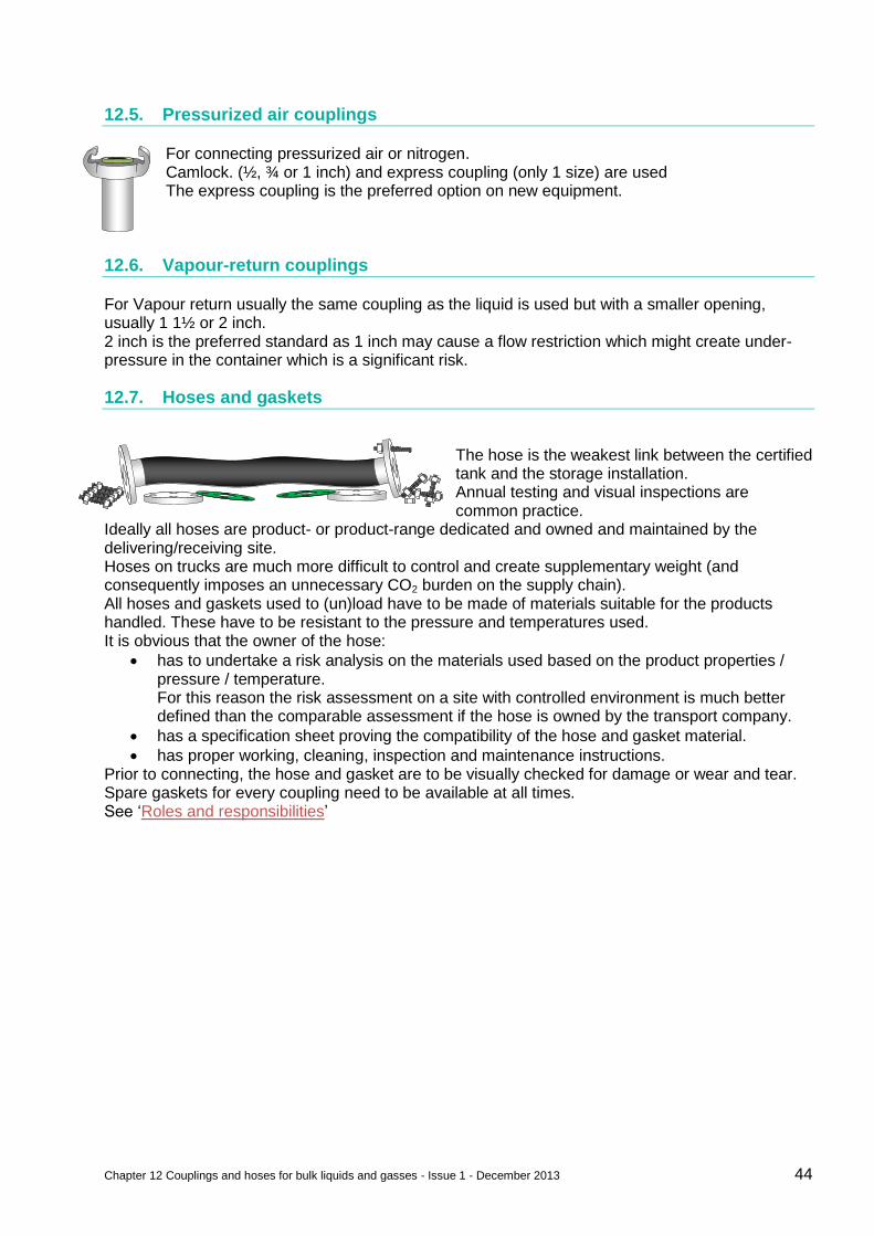
Chapter 12 Couplings and hoses for bulk liquids and gasses - Issue 1 - December 2013 44
12.5. Pressurized air couplings
For connecting pressurized air or nitrogen. Camlock. (½, ¾ or 1 inch) and express coupling (only 1 size) are used The express coupling is the preferred option on new equipment.
12.6. Vapour-return couplings
For Vapour return usually the same coupling as the liquid is used but with a smaller opening, usually 1 1½ or 2 inch. 2 inch is the preferred standard as 1 inch may cause a flow restriction which might create under-pressure in the container which is a significant risk.
12.7. Hoses and gaskets
The hose is the weakest link between the certified tank and the storage installation. Annual testing and visual inspections are common practice.
Ideally all hoses are product- or product-range dedicated and owned and maintained by the delivering/receiving site. Hoses on trucks are much more difficult to control and create supplementary weight (and consequently imposes an unnecessary CO2 burden on the supply chain). All hoses and gaskets used to (un)load have to be made of materials suitable for the products handled. These have to be resistant to the pressure and temperatures used. It is obvious that the owner of the hose:
has to undertake a risk analysis on the materials used based on the product properties / pressure / temperature. For this reason the risk assessment on a site with controlled environment is much better defined than the comparable assessment if the hose is owned by the transport company.
has a specification sheet proving the compatibility of the hose and gasket material.
has proper working, cleaning, inspection and maintenance instructions. Prior to connecting, the hose and gasket are to be visually checked for damage or wear and tear. Spare gaskets for every coupling need to be available at all times. See ‘Roles and responsibilities’

Contact list 45
Contact list
Steven Beddegenoodts Global SHERQ manager SC SABIC SBU Chemicals M +31 6211 699 79
steven.beddegenoodts sabic-europe.com
Judith Kleinen Manager Land Transport & Spot Shipping SABIC SC Chem Europe T +31 46 722 2273 M +31 6 134 282 55
judith.kleinen sabic-europe.com
Jan Hendrik Leopold SSHEQ Manager R.M.I. Global Logistic Services T +31 10 283 11 00
janhendrik.leopold nl.rmi-global.com
Luc Van de Velde Logistics Safety Manager Ineos Olefins & Polymers Europe T + 32 3210 36 47 M + 32 475 27 23 31
Luc.vandevelde ineos.com
Philippe Neefs Distribution Safety Specialist Chevron Phillips Chemicals Int N.V. T+32 2689 1265 F+32 2689 1307
neefspm cpchem.com
Evert de Jong European HSSEQ Manager De Rijke Group M+31 181 654 292 M+31 653 789 646
Evert.deJong derijke.com
Maayke Van Noort ES&S Transportation Manager Benelux Dow Benelux BV T+31 115 671 334
mjvannoort dow.com
Marc Cabuy EMEAF Liquids Logistics SSHE Advisor ExxonMobil Chemical T+ 32 2 722 4063
marc.cabuy exxonmobil.com
Steve Rowland SHEQ Manager, UK,Europe and Americas Suttons Transport Group T+44 151 420 2020 M+44 7713 230 047
stephen.rowland suttonsgroup.com
Rob Montfoort HSSE Country Specialist Shell Chemicals Europe B.V. T+ 31 10441 6291 M+31 655 125 876
rob.montfoort shell.com
Jacques Declercq Secretary General M+32 475 451 457
Jacques.declercq bacd.be
Colin V Humphrey Managing Director Responsible Care Coordinator T +32(0)2 741 86 81 M + 44 (0) 781 732 5834
colinvhumphrey ecta.com
Victor Trapani SQAS Manager Cefic T+32 2676 7385 M+32 499 580 610
vtr cefic.be
Justin Lemmens Senior Sales Manager LKW WALTER Internationale Transportorganisation AG T+43 5 7777 4339 M+43 664 85 82 401
lemmens lkw-walter.com
Peter J C Newport Chief Executive Officer Chemical Business Association T +44 (0) 1270 252800 M +44 (0) 7786 515407
peter.newport chemical.org.uk
Jos Verlinden Director Transport and Logistics Cefic T+32 2676 7395 M+32 474 989033
jve cefic.be
Marc Twisk Project manager Transports Vervaeke T+32 2481 7693 M+32 498 580 608
mtw vervaeke.com
@
@
@
@ @ @
@ @ @
@
@
@
@
@
@
@ @
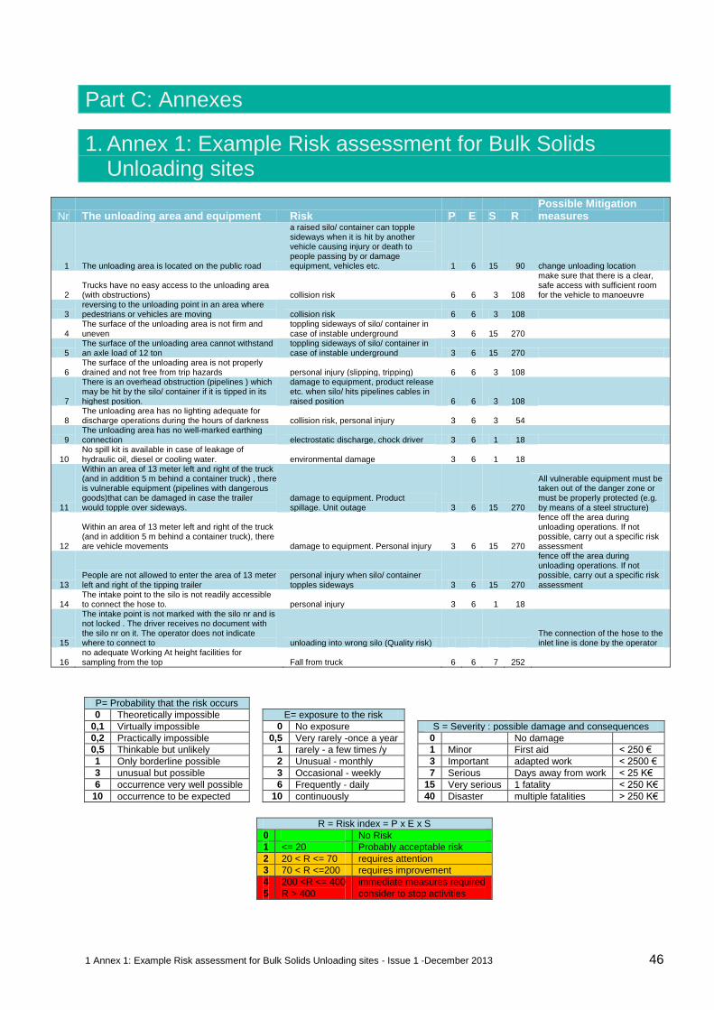
1 Annex 1: Example Risk assessment for Bulk Solids Unloading sites - Issue 1 -December 2013 46
Part C: Annexes
1. Annex 1: Example Risk assessment for Bulk Solids Unloading sites
Nr The unloading area and equipment Risk P E S R Possible Mitigation measures
1 The unloading area is located on the public road
a raised silo/ container can topple sideways when it is hit by another vehicle causing injury or death to people passing by or damage equipment, vehicles etc. 1 6 15 90 change unloading location
2 Trucks have no easy access to the unloading area (with obstructions) collision risk 6 6 3 108
make sure that there is a clear, safe access with sufficient room for the vehicle to manoeuvre
3 reversing to the unloading point in an area where pedestrians or vehicles are moving collision risk 6 6 3 108
4 The surface of the unloading area is not firm and uneven
toppling sideways of silo/ container in case of instable underground 3 6 15 270
5 The surface of the unloading area cannot withstand an axle load of 12 ton
toppling sideways of silo/ container in case of instable underground 3 6 15 270
6 The surface of the unloading area is not properly drained and not free from trip hazards personal injury (slipping, tripping) 6 6 3 108
7
There is an overhead obstruction (pipelines ) which may be hit by the silo/ container if it is tipped in its highest position.
damage to equipment, product release etc. when silo/ hits pipelines cables in raised position 6 6 3 108
8 The unloading area has no lighting adequate for discharge operations during the hours of darkness collision risk, personal injury 3 6 3 54
9 The unloading area has no well-marked earthing connection electrostatic discharge, chock driver 3 6 1 18
10
No spill kit is available in case of leakage of
hydraulic oil, diesel or cooling water. environmental damage 3 6 1 18
11
Within an area of 13 meter left and right of the truck (and in addition 5 m behind a container truck) , there is vulnerable equipment (pipelines with dangerous goods)that can be damaged in case the trailer would topple over sideways.
damage to equipment. Product spillage. Unit outage 3 6 15 270
All vulnerable equipment must be taken out of the danger zone or must be properly protected (e.g. by means of a steel structure)
12
Within an area of 13 meter left and right of the truck (and in addition 5 m behind a container truck), there are vehicle movements damage to equipment. Personal injury 3 6 15 270
fence off the area during unloading operations. If not possible, carry out a specific risk assessment
13 People are not allowed to enter the area of 13 meter left and right of the tipping trailer
personal injury when silo/ container topples sideways 3 6 15 270
fence off the area during unloading operations. If not possible, carry out a specific risk assessment
14 The intake point to the silo is not readily accessible to connect the hose to. personal injury 3 6 1 18
15
The intake point is not marked with the silo nr and is not locked . The driver receives no document with the silo nr on it. The operator does not indicate where to connect to unloading into wrong silo (Quality risk)
The connection of the hose to the inlet line is done by the operator
16 no adequate Working At height facilities for sampling from the top Fall from truck 6 6 7 252
P= Probability that the risk occurs 0 Theoretically impossible
E= exposure to the risk 0,1 Virtually impossible
0 No exposure
S = Severity : possible damage and consequences
0,2 Practically impossible
0,5 Very rarely -once a year
0 No damage
0,5 Thinkable but unlikely
1 rarely - a few times /y
1 Minor First aid < 250 €
1 Only borderline possible
2 Unusual - monthly
3 Important adapted work < 2500 €
3 unusual but possible
3 Occasional - weekly
7 Serious Days away from work < 25 K€
6 occurrence very well possible
6 Frequently - daily
15 Very serious 1 fatality < 250 K€
10 occurrence to be expected
10 continuously
40 Disaster multiple fatalities > 250 K€
R = Risk index = P x E x S
0 No Risk
1 <= 20 Probably acceptable risk
2 20 < R <= 70 requires attention
3 70 < R <=200 requires improvement
4 200 <R <= 400 immediate measures required
5 R > 400 consider to stop activities
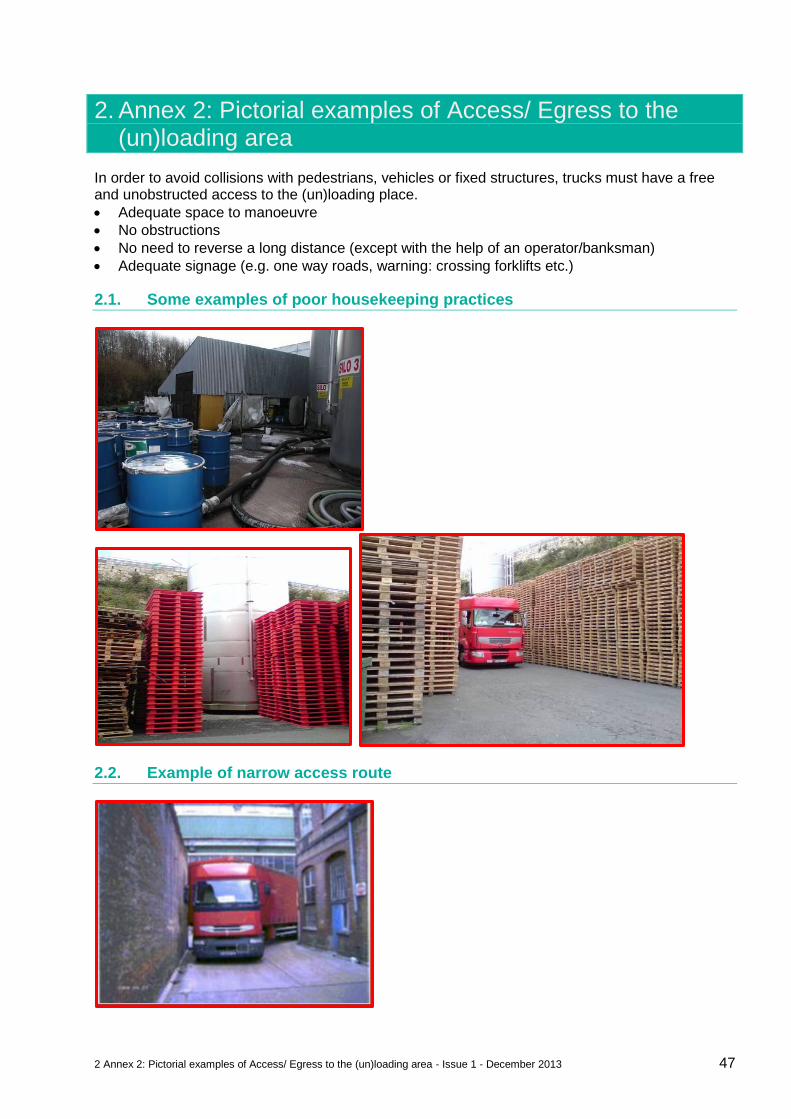
2 Annex 2: Pictorial examples of Access/ Egress to the (un)loading area - Issue 1 - December 2013 47
2. Annex 2: Pictorial examples of Access/ Egress to the (un)loading area
In order to avoid collisions with pedestrians, vehicles or fixed structures, trucks must have a free and unobstructed access to the (un)loading place.
Adequate space to manoeuvre
No obstructions
No need to reverse a long distance (except with the help of an operator/banksman)
Adequate signage (e.g. one way roads, warning: crossing forklifts etc.)
2.1. Some examples of poor housekeeping practices
2.2. Example of narrow access route
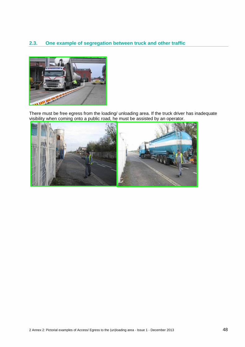
2 Annex 2: Pictorial examples of Access/ Egress to the (un)loading area - Issue 1 - December 2013 48
2.3. One example of segregation between truck and other traffic
There must be free egress from the loading/ unloading area. If the truck driver has inadequate visibility when coming onto a public road, he must be assisted by an operator.
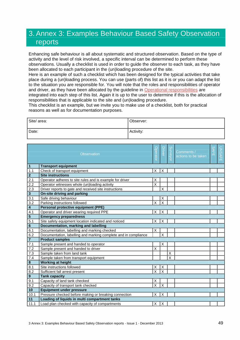
3 Annex 3: Examples Behaviour Based Safety Observation reports - Issue 1 - December 2013 49
3. Annex 3: Examples Behaviour Based Safety Observation reports
Enhancing safe behaviour is all about systematic and structured observation. Based on the type of activity and the level of risk involved, a specific interval can be determined to perform these observations. Usually a checklist is used in order to guide the observer to each task, as they have been allocated to each participant in the (un)loading procedure of the site. Here is an example of such a checklist which has been designed for the typical activities that take place during a (un)loading process. You can use (parts of) this list as it is or you can adapt the list to the situation you are responsible for. You will note that the roles and responsibilities of operator and driver, as they have been allocated by the guideline in Operational responsibilities are integrated into each step of this list. Again it is up to the user to determine if this is the allocation of responsibilities that is applicable to the site and (un)loading procedure. This checklist is an example, but we invite you to make use of a checklist, both for practical reasons as well as for documentation purposes.
Site/ area:
Observer:
Date:
Activity:
Observation
Op
era
tor
Driv
er
Su
rveyo
r
Comments / actions to be taken
SA
FE
UN
SA
FE
1 Transport equipment
1.1 Check of transport equipment X X
2 Site instructions
2.1 Operator adheres to site rules and is example for driver X
2.2 Operator witnesses whole (un)loading activity X
2.3 Driver reports to gate and received site instructions X
3 On-site driving and parking
3.1 Safe driving behaviour X
3.2 Parking instructions followed X X
4 Personal protective equipment (PPE)
4.1 Operator and driver wearing required PPE X X
5 Emergency preparedness
5.1 Site safety equipment location indicated and noticed X X
6 Documentation, marking and labelling
6.1 Documentation, labelling and marking checked X
6.2 Documentation, labelling and marking complete and in compliance X
7 Product samples
7.1 Sample present and handed to operator X
7.2 Sample present and handed to driver X
7.3 Sample taken from land tank X
7.4 Sample taken from transport equipment X
8 Working at height
8.1 Site instructions followed X X
8.2 Sufficient fall arrest present X X
9 Tank capacity
9.1 Capacity of land tank checked X
9.2 Capacity of transport tank checked X X
10 Equipment under pressure
10.1 Pressure checked before making or breaking connection X X
11 Loading of liquids in multi compartment tanks
11.1 Load plan checked with capacity of compartments X X
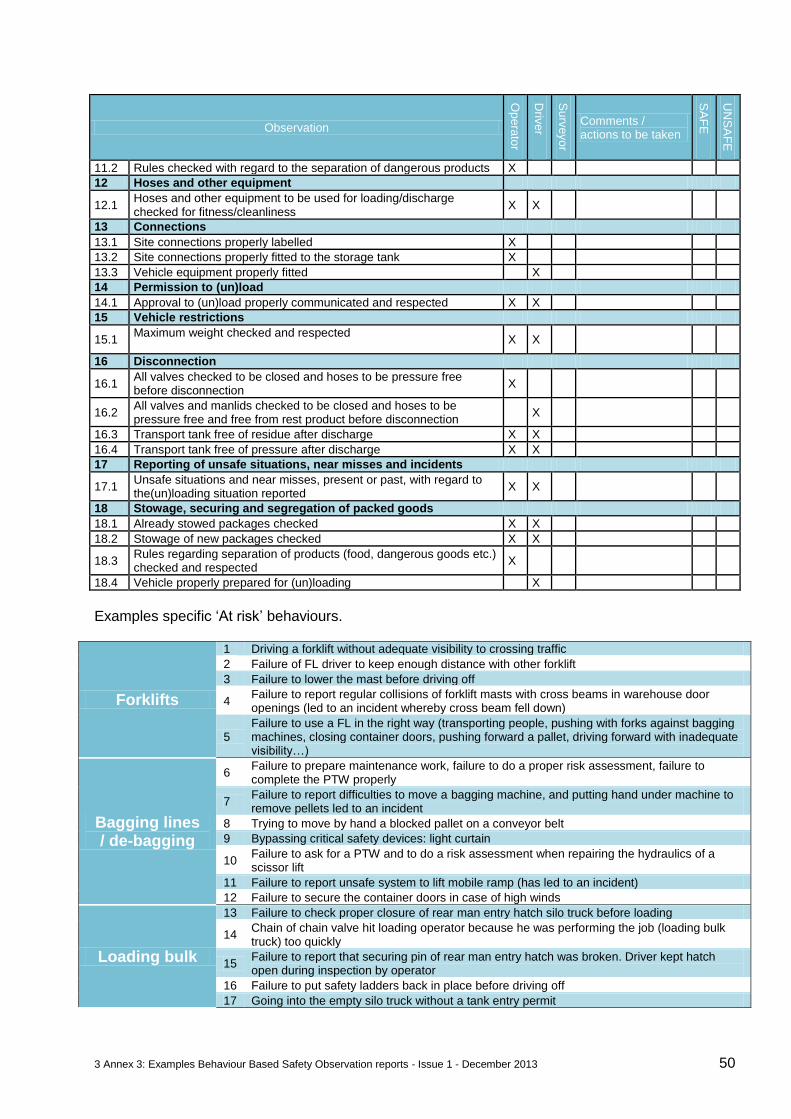
3 Annex 3: Examples Behaviour Based Safety Observation reports - Issue 1 - December 2013 50
Observation
Op
era
tor
Driv
er
Su
rveyo
r
Comments / actions to be taken
SA
FE
UN
SA
FE
11.2 Rules checked with regard to the separation of dangerous products X
12 Hoses and other equipment
12.1 Hoses and other equipment to be used for loading/discharge checked for fitness/cleanliness
X X
13 Connections
13.1 Site connections properly labelled X
13.2 Site connections properly fitted to the storage tank X
13.3 Vehicle equipment properly fitted X
14 Permission to (un)load
14.1 Approval to (un)load properly communicated and respected X X
15 Vehicle restrictions
15.1 Maximum weight checked and respected
X X
16 Disconnection
16.1 All valves checked to be closed and hoses to be pressure free before disconnection
X
16.2 All valves and manlids checked to be closed and hoses to be pressure free and free from rest product before disconnection
X
16.3 Transport tank free of residue after discharge X X
16.4 Transport tank free of pressure after discharge X X
17 Reporting of unsafe situations, near misses and incidents
17.1 Unsafe situations and near misses, present or past, with regard to the(un)loading situation reported
X X
18 Stowage, securing and segregation of packed goods
18.1 Already stowed packages checked X X
18.2 Stowage of new packages checked X X
18.3 Rules regarding separation of products (food, dangerous goods etc.) checked and respected
X
18.4 Vehicle properly prepared for (un)loading X
Examples specific ‘At risk’ behaviours.
Forklifts
1 Driving a forklift without adequate visibility to crossing traffic
2 Failure of FL driver to keep enough distance with other forklift
3 Failure to lower the mast before driving off
4 Failure to report regular collisions of forklift masts with cross beams in warehouse door openings (led to an incident whereby cross beam fell down)
5 Failure to use a FL in the right way (transporting people, pushing with forks against bagging machines, closing container doors, pushing forward a pallet, driving forward with inadequate visibility…)
Bagging lines / de-bagging
6 Failure to prepare maintenance work, failure to do a proper risk assessment, failure to complete the PTW properly
7 Failure to report difficulties to move a bagging machine, and putting hand under machine to remove pellets led to an incident
8 Trying to move by hand a blocked pallet on a conveyor belt
9 Bypassing critical safety devices: light curtain
10 Failure to ask for a PTW and to do a risk assessment when repairing the hydraulics of a scissor lift
11 Failure to report unsafe system to lift mobile ramp (has led to an incident)
12 Failure to secure the container doors in case of high winds
Loading bulk
13 Failure to check proper closure of rear man entry hatch silo truck before loading
14 Chain of chain valve hit loading operator because he was performing the job (loading bulk truck) too quickly
15 Failure to report that securing pin of rear man entry hatch was broken. Driver kept hatch open during inspection by operator
16 Failure to put safety ladders back in place before driving off
17 Going into the empty silo truck without a tank entry permit
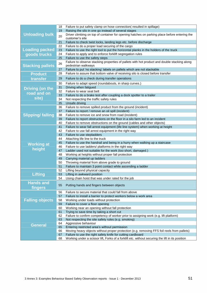
3 Annex 3: Examples Behaviour Based Safety Observation reports - Issue 1 - December 2013 51
Unloading bulk
18 Failure to put safety clamp on hose connection( resulted in spillage)
19 Raising the silo in one go instead of several stages
20 Driver climbing on top of container for opening hatches on parking place before entering the customer’s site
21 Failure to check twist locks, landing legs etc. before discharge
Loading packed goods trucks
22 Failure to do a proper load securing of the cargo
23 Failure to use the right tool to put the horizontal planks in the holders of the truck
24 Failure to apply and to enforce forklift segregation rules
25 Failure to use the safety steps
Stacking pallets 26
Failure to observe stacking properties of pallets with hot product and double stacking along pedestrian walkways
27 Failure to put ‘no stacking’ labels on pallets which are not stackable
Product transfer
28 Failure to assure that bottom valve of receiving silo is closed before transfer
29 Failure to do a check during transfer operations
Driving (on the road and on
site)
30 Failure to adapt speed (roundabouts, in sharp curves.)
31 Driving when fatigued
32 Failure to wear seat belt
33 Failure to do a brake test after coupling a dock spotter to a trailer
34 Not respecting the traffic safety rules
35 Unsafe driving
Slipping/ falling
36 Failure to remove spilled product from the ground (incident)
37 Failure to report / remove an oil spill (incident)
38 Failure to remove ice and snow from road (incident)
39 Failure to report obstructions on the floor in a silo farm led to an incident
40 Failure to remove obstructions on the ground (cables and other objects)
Working at height
41 Failure to wear fall arrest equipment (life line system) when working at height
42 Failure to use fall arrest equipment in the right way
43 Failure to use stepladders
44 Attaching life line to the truck
45 Failure to use the handrail and being in a hurry when walking up a staircase
46 Failure to use ladders/ platforms in the right way
47 Ladder used not suitable for the work (too short, damaged.)
48 Working at heights without proper fall protection
49 Carrying material up ladders
50 Throwing material from above grade to ground
51 Failure to maintain 3 point contact while ascending a ladder
Lifting 52 Lifting beyond physical capacity
53 Lifting in awkward position
54 Using chain hoist that was under rated for the job
Hands and fingers
55 Putting hands and fingers between objects
Falling objects
56 Failure to secure material that could fall from above
57 Failure to install a barrier to protect workers below a work area
58 Working under loads without protection
59 Failure to cover a floor opening
60 Working near an opening without fall protection
General
61 Trying to save time by taking a short cut
62 Failure to confirm competency of worker prior to assigning work (e.g. lift platform)
63 Not respecting the site safety rules (e.g. smoking)
64 Aggressive behaviour
65 Entering restricted area’s without permission
66 Moving heavy objects without proper protection (e.g. removing FFS foil reels from pallets)
67 Failure to use the right safety knife for cutting cardboard
68 Working under a scissor lift, Forks of a forklift etc. without securing the lift in its position
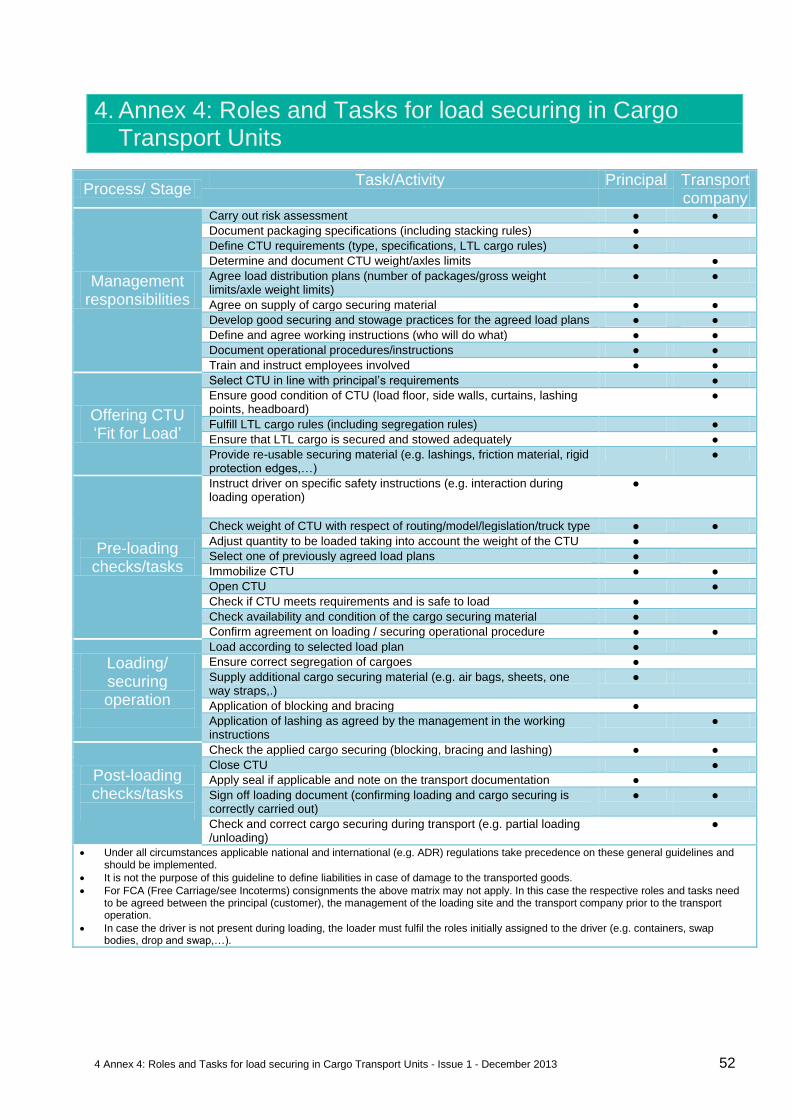
4 Annex 4: Roles and Tasks for load securing in Cargo Transport Units - Issue 1 - December 2013 52
4. Annex 4: Roles and Tasks for load securing in Cargo Transport Units
Process/ Stage Task/Activity Principal Transport
company
Management responsibilities
Carry out risk assessment ● ●
Document packaging specifications (including stacking rules) ●
Define CTU requirements (type, specifications, LTL cargo rules) ●
Determine and document CTU weight/axles limits ●
Agree load distribution plans (number of packages/gross weight limits/axle weight limits)
● ●
Agree on supply of cargo securing material ● ●
Develop good securing and stowage practices for the agreed load plans ● ●
Define and agree working instructions (who will do what) ● ●
Document operational procedures/instructions ● ●
Train and instruct employees involved ● ●
Offering CTU ‘Fit for Load’
Select CTU in line with principal’s requirements ●
Ensure good condition of CTU (load floor, side walls, curtains, lashing points, headboard)
●
Fulfill LTL cargo rules (including segregation rules) ●
Ensure that LTL cargo is secured and stowed adequately ●
Provide re-usable securing material (e.g. lashings, friction material, rigid protection edges,…)
●
Pre-loading checks/tasks
Instruct driver on specific safety instructions (e.g. interaction during loading operation)
●
Check weight of CTU with respect of routing/model/legislation/truck type ● ●
Adjust quantity to be loaded taking into account the weight of the CTU ●
Select one of previously agreed load plans ●
Immobilize CTU ● ●
Open CTU ●
Check if CTU meets requirements and is safe to load ●
Check availability and condition of the cargo securing material ●
Confirm agreement on loading / securing operational procedure ● ●
Loading/ securing operation
Load according to selected load plan ●
Ensure correct segregation of cargoes ●
Supply additional cargo securing material (e.g. air bags, sheets, one way straps,.)
●
Application of blocking and bracing ●
Application of lashing as agreed by the management in the working instructions
●
Post-loading checks/tasks
Check the applied cargo securing (blocking, bracing and lashing) ● ●
Close CTU ●
Apply seal if applicable and note on the transport documentation ●
Sign off loading document (confirming loading and cargo securing is correctly carried out)
● ●
Check and correct cargo securing during transport (e.g. partial loading /unloading)
●
Under all circumstances applicable national and international (e.g. ADR) regulations take precedence on these general guidelines and should be implemented.
It is not the purpose of this guideline to define liabilities in case of damage to the transported goods.
For FCA (Free Carriage/see Incoterms) consignments the above matrix may not apply. In this case the respective roles and tasks need to be agreed between the principal (customer), the management of the loading site and the transport company prior to the transport operation.
In case the driver is not present during loading, the loader must fulfil the roles initially assigned to the driver (e.g. containers, swap bodies, drop and swap,…).
PROCESS / STAGE TASK / ACTIVITY LOADER DRIVER
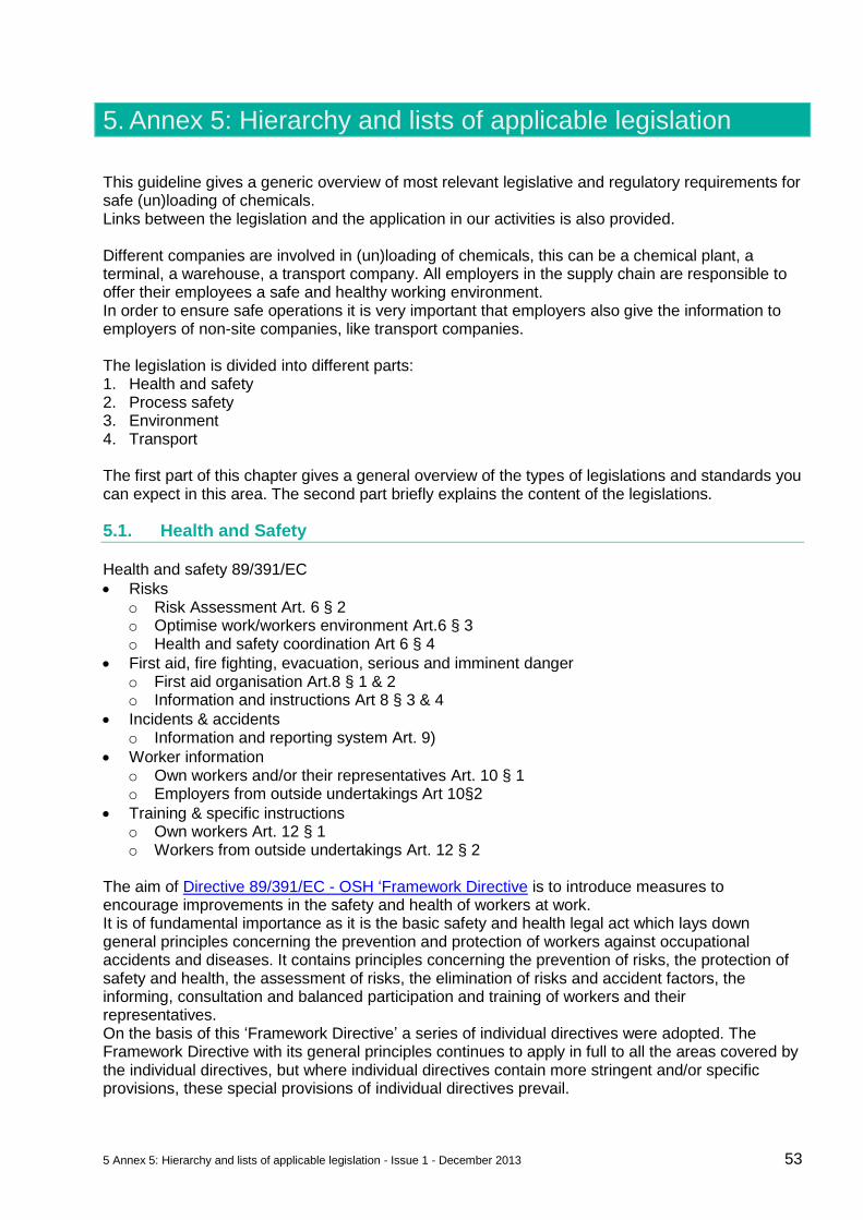
5 Annex 5: Hierarchy and lists of applicable legislation - Issue 1 - December 2013 53
5. Annex 5: Hierarchy and lists of applicable legislation
This guideline gives a generic overview of most relevant legislative and regulatory requirements for safe (un)loading of chemicals. Links between the legislation and the application in our activities is also provided. Different companies are involved in (un)loading of chemicals, this can be a chemical plant, a terminal, a warehouse, a transport company. All employers in the supply chain are responsible to offer their employees a safe and healthy working environment. In order to ensure safe operations it is very important that employers also give the information to employers of non-site companies, like transport companies. The legislation is divided into different parts: 1. Health and safety 2. Process safety 3. Environment 4. Transport The first part of this chapter gives a general overview of the types of legislations and standards you can expect in this area. The second part briefly explains the content of the legislations.
5.1. Health and Safety
Health and safety 89/391/EC
Risks o Risk Assessment Art. 6 § 2 o Optimise work/workers environment Art.6 § 3 o Health and safety coordination Art 6 § 4
First aid, fire fighting, evacuation, serious and imminent danger o First aid organisation Art.8 § 1 & 2 o Information and instructions Art 8 § 3 & 4
Incidents & accidents o Information and reporting system Art. 9)
Worker information o Own workers and/or their representatives Art. 10 § 1 o Employers from outside undertakings Art 10§2
Training & specific instructions o Own workers Art. 12 § 1 o Workers from outside undertakings Art. 12 § 2
The aim of Directive 89/391/EC - OSH ‘Framework Directive is to introduce measures to encourage improvements in the safety and health of workers at work. It is of fundamental importance as it is the basic safety and health legal act which lays down general principles concerning the prevention and protection of workers against occupational accidents and diseases. It contains principles concerning the prevention of risks, the protection of safety and health, the assessment of risks, the elimination of risks and accident factors, the informing, consultation and balanced participation and training of workers and their representatives. On the basis of this ‘Framework Directive’ a series of individual directives were adopted. The Framework Directive with its general principles continues to apply in full to all the areas covered by the individual directives, but where individual directives contain more stringent and/or specific provisions, these special provisions of individual directives prevail.
5 Annex 5: Hierarchy and lists of applicable legislation - Issue 1 - December 2013 54
The specific situation for loading and unloading is the cooperation between different employers. The directive states in article 10 point 2 how to handle this. Art 10 point 2 obliges employers to give information to employers of outside undertaking. See the Communication from the Commission to the European Parliament, the Council, the European Economic and Social Committee and the Committee of Regions on the practical implementation of the provisions of the Health and Safety at Work Directives 89/391 (Framework), 89/654 (Workplaces), 89/655 (Work Equipment), 89/656 (Personal Protective Equipment), 90/269 (Manual Handling of Loads) and 90/270 (Display Screen Equipment)
5.2. Process Safety
Management systems o Risk Assessment o Management of Change o Learning from Incidents
Fire Safety o Fire safety Directive o ATEX Explosive Atmospheres Atex 118a; Dir_1999_92
Equipment requirements o Safety in Pressure Vessels EN 13445 (97/23/EC) o Machine directive 2006/42/EC o CE marking 93/68/EC o Design of Installations different standards
Storage requirements
local legislation General: Process Safety directives are not available in EU. In general process safety management is a set of tools that focuses on preventing releases of any substance that have a high risk to the environment like toxic reactive of flammable liquids or gasses. A risk analyses on potential release of chemicals, the effect of such a release and the mitigating measures should ALWAYS be assessed, also when a material is not classified. For every country different standards can apply and also different ways are available to present to guidelines. For UK : https://www.gov.uk/browse/business/manufacturing/manufacturing-regulations
5.3. Environment
Emissions to air, soil and water o Directive 2010/75/EC (Integrated pollution prevention control - IPPC)
Directive 2008/50/EC (Air Pollution) National Air Emission legislation Proposal for a Soil Framework Directive (COM(2006) 231) National Soil pollution legislation Water Framework Directive 2000/60/EC National Water pollution legislation
Waste Control o 2008 EU Waste Framework Directive
National Legislation on Waste Control
Noise Control o Environmental Noise Directive 2002/49/EC
National Legislation on Noise Control
5 Annex 5: Hierarchy and lists of applicable legislation - Issue 1 - December 2013 55
The Environment legislation is divided in different aspects/ compartments: General: The general information can be found on the EU website: http://ec.europa.eu/environment/sme/legislation/legislation_en.htm
Emission to air, soil and Water
Air quality, emissions trading and noise
Chemicals (REACH)
Energy
Environmental management (EMAS, Life Cycle Assessment, CSR)
Greener products (Green Public Procurement, EU Ecolabel, Integrated Product Policy, Eco-design, WEEE, RoHS, ELV, EuP )
Water
Soil
Containment (Nederlandse Richtlijn Bodembescherming = NRB zit ook in PGS 15)
Waste control
Waste o Cleaning of transport equipment o Empty packaging
State aid for environmental protection
5.4. Transportation
5.4.1. General transport legislation
Transport is regulated both on a national and European level. A general overview on the Regulations for the different modes with EU-directives is available at following website: http://europa.eu/legislation_summaries/transport/index_en.htm
5.4.2. Load securing
See ADR 7.5.7.1 related to the stowage
General cargo : o European Best Practice Guidelines on Cargo Securing for Road Transport
http://ec.europa.eu/transport/road_safety/vehicles/doc/cargo_securing_guidelines_en.pdf o The requirements of paragraph 7.5.7.1 of ADR are deemed to be complied with if the cargo
is secured in accordance with standard EN 12195-1:2010
For class 2 receptacles : o Load securing of class 2 receptacles – IGC Doc 52/06/E
http://www.mobilit.fgov.be/data/route/adr/Doc_52_06_E.pdf For rail see
www.gcubureau.com, January 2013 appendix 9, code 7.x.x and following
“loading guidelines” of RIV at www.uic.org version January 2013 http://www.uic.org/etf/rivric/riv-ric.pdf
5.4.3. CMR Convention
CMR : Convention on the contract for International Carriage of Goods by Road
5.4.4. ADR
European Agreement concerning the International Carriage of Dangerous Goods by Road.
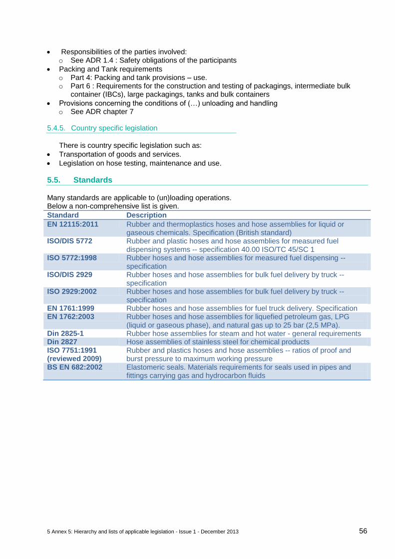
5 Annex 5: Hierarchy and lists of applicable legislation - Issue 1 - December 2013 56
Responsibilities of the parties involved: o See ADR 1.4 : Safety obligations of the participants
Packing and Tank requirements o Part 4: Packing and tank provisions – use. o Part 6 : Requirements for the construction and testing of packagings, intermediate bulk
container (IBCs), large packagings, tanks and bulk containers
Provisions concerning the conditions of (…) unloading and handling o See ADR chapter 7
5.4.5. Country specific legislation
There is country specific legislation such as:
Transportation of goods and services.
Legislation on hose testing, maintenance and use.
5.5. Standards
Many standards are applicable to (un)loading operations. Below a non-comprehensive list is given.
Standard Description
EN 12115:2011 Rubber and thermoplastics hoses and hose assemblies for liquid or gaseous chemicals. Specification (British standard)
ISO/DIS 5772 Rubber and plastic hoses and hose assemblies for measured fuel dispensing systems -- specification 40.00 ISO/TC 45/SC 1
ISO 5772:1998 Rubber hoses and hose assemblies for measured fuel dispensing -- specification
ISO/DIS 2929 Rubber hoses and hose assemblies for bulk fuel delivery by truck -- specification
ISO 2929:2002 Rubber hoses and hose assemblies for bulk fuel delivery by truck -- specification
EN 1761:1999 Rubber hoses and hose assemblies for fuel truck delivery. Specification EN 1762:2003 Rubber hoses and hose assemblies for liquefied petroleum gas, LPG
(liquid or gaseous phase), and natural gas up to 25 bar (2,5 MPa). Din 2825-1 Rubber hose assemblies for steam and hot water - general requirements Din 2827 Hose assemblies of stainless steel for chemical products ISO 7751:1991 (reviewed 2009)
Rubber and plastics hoses and hose assemblies -- ratios of proof and burst pressure to maximum working pressure
BS EN 682:2002 Elastomeric seals. Materials requirements for seals used in pipes and fittings carrying gas and hydrocarbon fluids
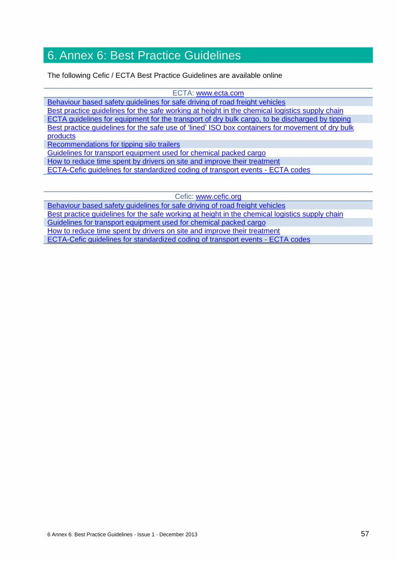
6 Annex 6: Best Practice Guidelines - Issue 1 - December 2013 57
6. Annex 6: Best Practice Guidelines
The following Cefic / ECTA Best Practice Guidelines are available online
ECTA: www.ecta.com
Behaviour based safety guidelines for safe driving of road freight vehicles Best practice guidelines for the safe working at height in the chemical logistics supply chain ECTA guidelines for equipment for the transport of dry bulk cargo, to be discharged by tipping Best practice guidelines for the safe use of ‘lined’ ISO box containers for movement of dry bulk products Recommendations for tipping silo trailers Guidelines for transport equipment used for chemical packed cargo How to reduce time spent by drivers on site and improve their treatment ECTA-Cefic guidelines for standardized coding of transport events - ECTA codes
Cefic: www.cefic.org
Behaviour based safety guidelines for safe driving of road freight vehicles Best practice guidelines for the safe working at height in the chemical logistics supply chain Guidelines for transport equipment used for chemical packed cargo How to reduce time spent by drivers on site and improve their treatment ECTA-Cefic guidelines for standardized coding of transport events - ECTA codes
7 Annex 7: Examples of Risks and Risk mitigation for (un)loading operations - Issue 1 - December 2013 58
7. Annex 7: Examples of Risks and Risk mitigation for (un)loading operations
7.1. Technical requirements (un)loading places
This chapter gives a brief overview of possible technical measures that can be taken to mitigate the risks that can occur at an (un)loading place. Examples of risks can be: overflow, over pressure, under pressure, exposure to product, exposure to vapours, fire/explosion, chemical reactions, unwanted movement of vehicles, fall from vehicle, high temperatures of product, etc. It is the responsibility of the (un)loading sites to assess the risks of (un)loading operation and to determine the measures to be taken. They are dependent on the potential effect of the failure as well as the probability. The risk can be product related, e.g. if the risk is an overflow of a tank the effects will be much more severe if the tank contains a very toxic material than if the tank contains water. Also the quantity of the product involved can play a role in the potential effect. Examples of risk tables of products, split into different groups, to illustrate the potential different risks and measures that could be taken are found below Reactive chemicals include those which are inherently unstable and susceptible to rapid decomposition as well as chemicals which, under specific conditions, can react alone, or with other substances in a violent uncontrolled manner, liberating heat, toxic gases, or leading to an explosion Flammable liquids include products with a flashpoint of <60°C or in case the flashpoint is above 60°C handled with a temperature above the flashpoint. Toxic liquids include products which are toxic for inhalation, exposure to skin or ingestion. Other classified products which are all products classified according to dangerous goods legislation except the ones mentioned above. Dry bulk, product that are solid particles and shipped in bulk silo’s. For technical requirements of unloading facilities for dry bulk, see also Guidelines for the Safe Tipping of Silo/Bulk/Containers and Tanks Non classified product, which are all the other products. Please note that to define the risk of the product handled the product properties need to be reviewed. The below tables give an impression of the possible technical measures than can be installed to mitigate the risk and also shows the possible relation to the product risks. The list is not mandatory to be applied. However it is mandatory to do a risk assessment and define for the specific situation what measures must be taken. Some measures are specifically mentioned in legislation in that case it is mandatory.
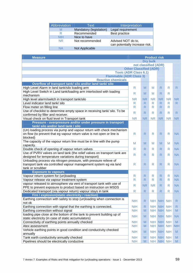
7 Annex 7: Examples of Risks and Risk mitigation for (un)loading operations - Issue 1 - December 2013 59
Abbreviation Text Interpretation M Mandatory (legislation) Legal requirement R Recommended Best practice
NtH Nice to have NR Not recommended Advised NOT do to,
can potentially increase risk. NA Not Applicable
Measure Product risk Dry bulk not classified (ADR) Other Classified (ADR) Toxic (ADR Class 6.1) Flammable (ADR Class 3) Reactive chemicals
Overflow of transport tank/ silo and/or land tank/ silo
High Level Alarm in land tank/silo loading arm R M M R R R
High Level Switch in Land tank/loading arm interlocked with loading mechanism
R M M R R
High level alarm/switch in transport tank/silo NR NR NR NR NR NR
Level indicator land tank/ silo R R R R R R
Flow meter on filling line R R R R R
Use of checklist to determine empty space in receiving tank/ silo. To be confirmed by filler and receiver.
R R R R R R
Visual check on fluid level in Transport tank NR NR NR NR NR NR
Pressure - overpressure and/or under pressure in transport tank/ silo and/or land tank / silo
(Un) loading process via pump and vapour return with check mechanism on flow (to prevent that eg vapour return valve is not open or line is blocked)
R R R R R NA
The capacity of the vapour return line must be in line with the pump capacity.
M M M M M NA
Double check of opening of vapour return valves R R R R R NA
Use of PVRV valves on land tank (the relief valves on transport tank are designed for temperature variations during transport)
R R R R R NA
Unloading process via nitrogen pressure, with pressure relieve of transport tank via controlled vapour management system eg via land tank or scrubber
R R R R R NA
Exposure to vapours
Vapour return system for (un)loading R R R R R NA
Vapour release via vapour treatment system R R R R R NA
vapour released to atmosphere via vent of transport tank with use of PPE to prevent exposure to product based on instruction on MSDS
R NR NR R R NA
Dedicated transport (via vapour return) vapour stays in tank R R R R R NA
Fire / explosion(static electricity / reaction)
Earthing connection with safety to stop (un)loading when connection is not ok
NtH R NtH NtH NtH R
Earthing connection with signal that the earthing is connected. NtH R NtH NtH NtH R
Earthing connection without signal NtH M NtH NtH NtH M
loading pipe close at the bottom of the tank to prevent building up of static electricity (in case of static accumulators)
NtH M NtH NtH NtH NA
Connectivity of earthing points annually checked NtH M NtH NtH NtH M
Atex assessment NtH M NtH NtH NtH NtH
Vehicle earthing points in good condition and conductivity checked annually
NtH M NtH NtH NtH M
Tank earth conductivity annually checked NtH M NtH NtH NtH M
Pipelines should be electrically conductive NtH M NtH NtH NtH M
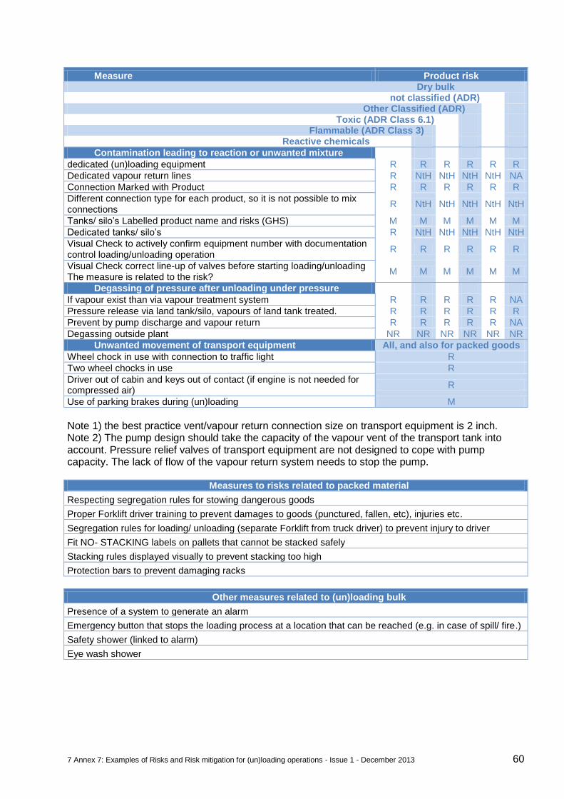
7 Annex 7: Examples of Risks and Risk mitigation for (un)loading operations - Issue 1 - December 2013 60
Measure Product risk Dry bulk not classified (ADR) Other Classified (ADR) Toxic (ADR Class 6.1) Flammable (ADR Class 3) Reactive chemicals
Contamination leading to reaction or unwanted mixture
dedicated (un)loading equipment R R R R R R
Dedicated vapour return lines R NtH NtH NtH NtH NA
Connection Marked with Product R R R R R R
Different connection type for each product, so it is not possible to mix connections
R NtH NtH NtH NtH NtH
Tanks/ silo’s Labelled product name and risks (GHS) M M M M M M
Dedicated tanks/ silo’s R NtH NtH NtH NtH NtH
Visual Check to actively confirm equipment number with documentation control loading/unloading operation
R R R R R R
Visual Check correct line-up of valves before starting loading/unloading The measure is related to the risk?
M M M M M M
Degassing of pressure after unloading under pressure
If vapour exist than via vapour treatment system R R R R R NA
Pressure release via land tank/silo, vapours of land tank treated. R R R R R R
Prevent by pump discharge and vapour return R R R R R NA
Degassing outside plant NR NR NR NR NR NR
Unwanted movement of transport equipment All, and also for packed goods
Wheel chock in use with connection to traffic light R
Two wheel chocks in use R
Driver out of cabin and keys out of contact (if engine is not needed for compressed air)
R
Use of parking brakes during (un)loading M
Note 1) the best practice vent/vapour return connection size on transport equipment is 2 inch. Note 2) The pump design should take the capacity of the vapour vent of the transport tank into account. Pressure relief valves of transport equipment are not designed to cope with pump capacity. The lack of flow of the vapour return system needs to stop the pump.
Measures to risks related to packed material
Respecting segregation rules for stowing dangerous goods
Proper Forklift driver training to prevent damages to goods (punctured, fallen, etc), injuries etc.
Segregation rules for loading/ unloading (separate Forklift from truck driver) to prevent injury to driver
Fit NO- STACKING labels on pallets that cannot be stacked safely
Stacking rules displayed visually to prevent stacking too high
Protection bars to prevent damaging racks
Other measures related to (un)loading bulk
Presence of a system to generate an alarm
Emergency button that stops the loading process at a location that can be reached (e.g. in case of spill/ fire.)
Safety shower (linked to alarm)
Eye wash shower
7 Annex 7: Examples of Risks and Risk mitigation for (un)loading operations - Issue 1 - December 2013 61
7.2. Examples of risk mitigation for non-standard operations
The HSE management system should consider all risks; it should contain all operations and the associated hazards. Enabling an organization to include all developments, changes and deviations from standard operations on a continuous basis, it is necessary to have a system in place to formally assess and address these situations. A ‘standard delivery’ to customer site for chemical products in bulk is characterized as follows:
Agreed transport company, loading and delivery dates, product volume and loading location.
Transport equipment is in line with common agreed practice and fits the order.
Appropriate shipping documents are present and no additional product handling during loading, transit or unloading is taking place (e.g. no local ad-hoc filtering or trans-loading into other truck / equipment).
Discharge fully at the agreed and known customer unloading location without return of product.
Unloading takes place in a bulk land tank.
No disruption after the discharge has started.
Agreed pressures, nitrogen blanketing and temperatures in the transport vessels in line with product requirements and common practice, before and after (un)loading.
An operation that is different from the definition of ‘standard’ described above is ‘non-standard operation (NSO)’. Suppliers and transport companies should proactively monitor these NSO’s and make sure to evaluate the operational risks. NSO’s increase the likelihood of errors and incidents and could place drivers, operators or the environment at risk. Therefore it is necessary to carry out risk analysis and to either eliminate any NSO or to manage the risk to an acceptable low level. Giving continuous developments, changes and deviations of processes, it is not possible to make an extensive NSO list. However regularly occurring NSO’s have been identified with suggested control mechanisms as listed below:
Unloading into drums and IBC and directly into containers.
Insufficient capacity of the storage tank
Unloading into multiple tanks or incomplete unloading
Drop off / parking of containers
Trans-loading between containers
Adding additives directly in to the transport vessel. Transport companies are encouraged to report NSO and / or potentially unsafe situations to the supplying chemical company. If a driver is in doubt whether the unloading operation can be done safely, he should not commence discharging and contact his planning department who can subsequently ask support from the supplier. Below are three examples on how to handle non-standard operations that can be used to benchmark internal processes. Companies can have different approaches to mitigate the risk, but the goal is always no harm to people, environment and assets.
7.2.1. Direct Discharge from Bulk Equipment into IBC or drums
The potential health, safety and environmental risks involved in unloading from bulk equipment directly into drums or Intermediate Bulk Containers (IBCs) without using a fixed installation are:
Loss of containment of product resulting from leakage, human error, malfunction of equipment or overfilling.
Human exposure and a potential for serious injury.
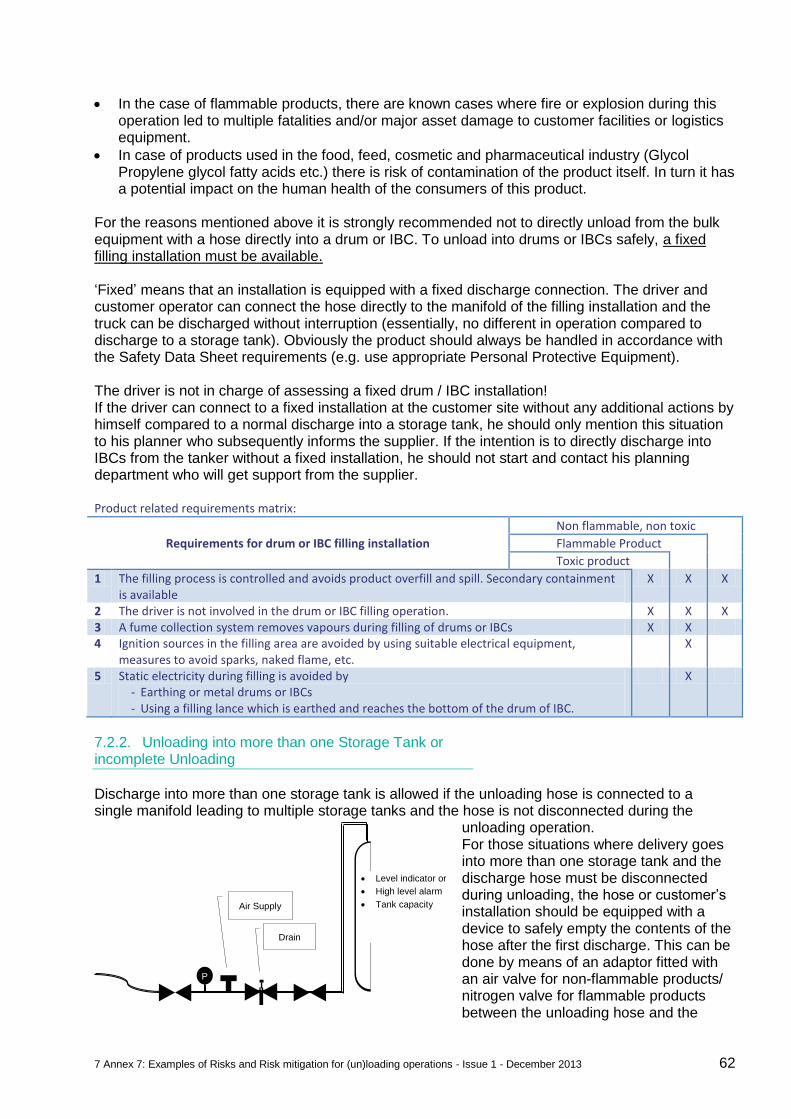
7 Annex 7: Examples of Risks and Risk mitigation for (un)loading operations - Issue 1 - December 2013 62
In the case of flammable products, there are known cases where fire or explosion during this operation led to multiple fatalities and/or major asset damage to customer facilities or logistics equipment.
In case of products used in the food, feed, cosmetic and pharmaceutical industry (Glycol Propylene glycol fatty acids etc.) there is risk of contamination of the product itself. In turn it has a potential impact on the human health of the consumers of this product.
For the reasons mentioned above it is strongly recommended not to directly unload from the bulk equipment with a hose directly into a drum or IBC. To unload into drums or IBCs safely, a fixed filling installation must be available. ‘Fixed’ means that an installation is equipped with a fixed discharge connection. The driver and customer operator can connect the hose directly to the manifold of the filling installation and the truck can be discharged without interruption (essentially, no different in operation compared to discharge to a storage tank). Obviously the product should always be handled in accordance with the Safety Data Sheet requirements (e.g. use appropriate Personal Protective Equipment). The driver is not in charge of assessing a fixed drum / IBC installation! If the driver can connect to a fixed installation at the customer site without any additional actions by himself compared to a normal discharge into a storage tank, he should only mention this situation to his planner who subsequently informs the supplier. If the intention is to directly discharge into IBCs from the tanker without a fixed installation, he should not start and contact his planning department who will get support from the supplier.
Product related requirements matrix:
Requirements for drum or IBC filling installation
Non flammable, non toxic
Flammable Product
Toxic product
1 The filling process is controlled and avoids product overfill and spill. Secondary containment is available
X X X
2 The driver is not involved in the drum or IBC filling operation. X X X 3 A fume collection system removes vapours during filling of drums or IBCs X X 4 Ignition sources in the filling area are avoided by using suitable electrical equipment,
measures to avoid sparks, naked flame, etc. X
5 Static electricity during filling is avoided by - Earthing or metal drums or IBCs - Using a filling lance which is earthed and reaches the bottom of the drum of IBC.
X
7.2.2. Unloading into more than one Storage Tank or incomplete Unloading
Discharge into more than one storage tank is allowed if the unloading hose is connected to a single manifold leading to multiple storage tanks and the hose is not disconnected during the
unloading operation. For those situations where delivery goes into more than one storage tank and the discharge hose must be disconnected during unloading, the hose or customer’s installation should be equipped with a device to safely empty the contents of the hose after the first discharge. This can be done by means of an adaptor fitted with an air valve for non-flammable products/ nitrogen valve for flammable products between the unloading hose and the
PI
Air Supply
Drain
Level indicator or
High level alarm
Tank capacity
7 Annex 7: Examples of Risks and Risk mitigation for (un)loading operations - Issue 1 - December 2013 63
customer’s inlet connection (see illustration). Note how the adaptor allows the hose to be flushed back into the transport tank before it is connected to the next storage tank. This operation should be carried out by the customer with properly trained operators and technical equipment without exposing the driver to any risks.
7.2.3. Insufficient Capacity of Storage Tank
The customer should proactively confirm to the driver that there is sufficient free space in the receiving storage tank prior start of discharge. If for any reason the discharge cannot be completed then the truck driver should wait until there is enough space in the receiving customer’s tank to resume the discharge operation safely. If this is not possible within a realistic timeframe and the truck cannot be completely unloaded, this should be recorded in the remark field of the transport document and the supplier should be informed accordingly. Ideally, handling of the hose should be done as described in the paragraph Unloading into more than one Storage tank or incomplete loading and the incident should be recorded by the parties involved. Any partially loaded vehicles embarking on a return trip to the supplier should comply with the ‘80/20 rule’

8 Annex 8: (Un)loading expressions / list in English - Issue 1 - December 2013 64
8. Annex 8: (Un)loading expressions / list in English
For bi-lingual reference see www.transperanto.org Language lists are in English, Dutch, German, French, Italian, Spanish, Portuguese, Polish, Russian (Phonetic + Cyrillic), Romanian, Bulgarian (Phonetic + Cyrillic), Turkish, Hungarian, Czech, Slovak, Slovene, Croatian, Serbian, Swedish, Danish, Norwegian, Finnish, Latvian, Estonian, Lithuanian, Greek (Phonetic + Greek)
Gate house check
D.1 ADR certificate D.2 Border D.3 Call your boss D.4 No entry D.5 Fill in the paper D.6 Means of Identification D.7 Licence/Number plate D.8 Invoice D.9 Loading papers D.10 Shipment number D.11 Signature D.12 Tremcard equipment D.13 Fire extinguisher D.14 Lights D.15 Tyres D.16 Tomorrow D.17 Too Early D.18 Too Late D.19 Weigh ticket D.20 Seal D.21 Intercom
Emergency
E.1 All safe E.2 Assembly Point E.3 Emergency Drill E.4 Emergency situation E.5 Follow E.6 Evacuation E.7 Alarm signal E.8 Gas alarm E.9 Absorbant material E.10 Broom E.11 Spade E.12 First Aid E.13 Medical Centre
General
G.1 Dangerous Goods G.2 Driver G.3 Open G.4 Closed G.5 No G.6 Yes G.7 Damaged G.8 Not OK G.9 OK G.10 Go to G.11 Loading place G.12 Left G.13 Right G.14 Stay here G.15 Straight on G.16 Start G.17 Stop G.18 Wait G.19 Park here G.20 Parking place G.21 Weighbridge G.22 Safe G.23 Unsafe G.24 Tired G.25 Problem G.26 Papers
Loading Bulk
LB.1 Are all the outlets closed ?
LB.2 Bottom valve LB.3 Safety valve LB.4 Cleaning document LB.5 Compartment LB.6 Compartment size LB.7 Compressor LB.8 Pump LB.9 Connect LB.10 Disconnect LB.11 Contaminated LB.12 Coupling LB.13 Depressurize LB.14 Earthing connection LB.15 Emergency stop LB.16 Filling degree LB.17 Filter LB.18 Gasket LB.19 Hose LB.20 Manhole LB.21 Baffles / Surge
plates LB.22 Flange LB.23 Pressure test LB.24 Overfill protection LB.25 Nitrogen LB.26 Air LB.27 Vacuum LB.28 Vapour return LB.29 Sample LB.30 Not clean/dirty LB.31 Out of spec LB.32 Spill LB.33 Storage tank LB.34 Tank LB.35 Tank container ID
plate LB.36 Labels
Loading General
LG.1 Load LG.2 Unload / Discharge LG.3 Container LG.4 Container CSC plate LG.5 Truck LG.6 Axle weight LG.7 Tare weight (empty
weight) LG.8 Fall protection LG.9 Harness LG.10 No climbing LG.11 Finished LG.12 Kilograms LG.13 Quantity to be loaded LG.14 Max total weight LG.15 Not enough LG.16 Too much LG.17 Product not ready LG.18 Stay at your vehicle LG.19 Switch off engine LG.20 Placarding LG.21 Wheel chocks
Loading Packed
LP.1 Secure the load LP.2 Blocking material LP.3 Bracing LP.4 Double stacking LP.5 Free space LP.6 Lashing straps LP.7 Curtain LP.8 Load floor LP.9 Load plan LP.10 Trailer
Safety
S.1 Speed limit < 20/30 km/hr
S.2 No smoking S.3 No mobile phones S.4 No alcohol S.5 No photographs S.6 No passengers S.7 No animals S.8 Wear Safety Glasses S.9 Wear protective
clothing S.10 Wear helmet S.11 Wear safety shoes S.12 Wear gloves S.13 Safety shower S.14 Eye wash S.15 Safety Instructions
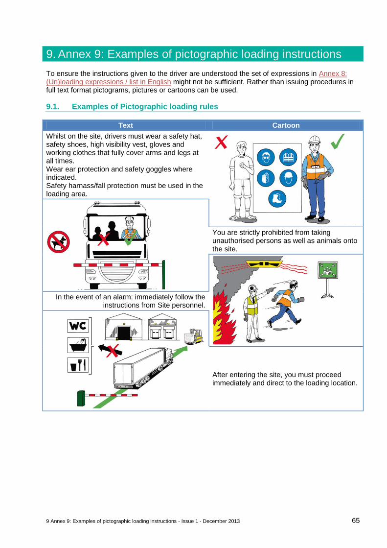
9 Annex 9: Examples of pictographic loading instructions - Issue 1 - December 2013 65
9. Annex 9: Examples of pictographic loading instructions
To ensure the instructions given to the driver are understood the set of expressions in Annex 8: (Un)loading expressions / list in English might not be sufficient. Rather than issuing procedures in full text format pictograms, pictures or cartoons can be used.
9.1. Examples of Pictographic loading rules
Text Cartoon
Whilst on the site, drivers must wear a safety hat, safety shoes, high visibility vest, gloves and working clothes that fully cover arms and legs at all times. Wear ear protection and safety goggles where indicated. Safety harnass/fall protection must be used in the loading area.
You are strictly prohibited from taking unauthorised persons as well as animals onto the site.
In the event of an alarm: immediately follow the instructions from Site personnel.
After entering the site, you must proceed immediately and direct to the loading location.
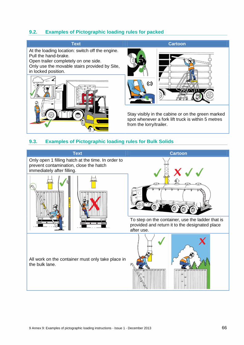
9 Annex 9: Examples of pictographic loading instructions - Issue 1 - December 2013 66
9.2. Examples of Pictographic loading rules for packed
Text Cartoon
At the loading location: switch off the engine. Pull the hand-brake. Open trailer completely on one side. Only use the movable stairs provided by Site, in locked position.
Stay visibly in the cabine or on the green marked spot whenever a fork lift truck is within 5 metres from the lorry/trailer.
9.3. Examples of Pictographic loading rules for Bulk Solids
Text Cartoon
Only open 1 filling hatch at the time. In order to prevent contamination, close the hatch immediately after filling.
To step on the container, use the ladder that is provided and return it to the designated place after use.
All work on the container must only take place in the bulk lane.