Embed Size (px)
Citation preview
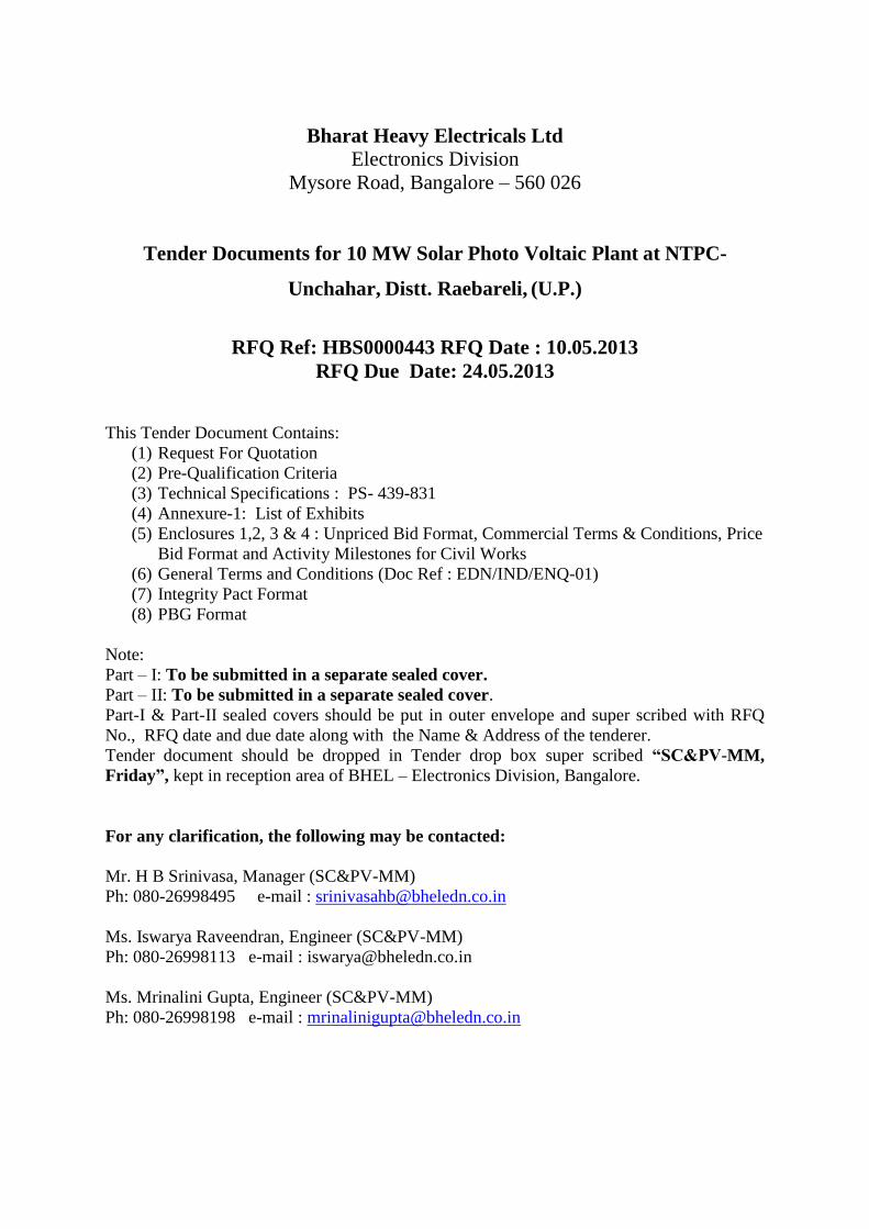
Bharat Heavy Electricals Ltd Electronics Division
Mysore Road, Bangalore – 560 026
Tender Documents for 10 MW Solar Photo Voltaic Plant at NTPC-
Unchahar, Distt. Raebareli, (U.P.)
RFQ Ref: HBS0000443 RFQ Date : 10.05.2013
RFQ Due Date: 24.05.2013
This Tender Document Contains:
(1) Request For Quotation
(2) Pre-Qualification Criteria
(3) Technical Specifications : PS- 439-831
(4) Annexure-1: List of Exhibits
(5) Enclosures 1,2, 3 & 4 : Unpriced Bid Format, Commercial Terms & Conditions, Price
Bid Format and Activity Milestones for Civil Works
(6) General Terms and Conditions (Doc Ref : EDN/IND/ENQ-01)
(7) Integrity Pact Format
(8) PBG Format
Note:
Part – I: To be submitted in a separate sealed cover.
Part – II: To be submitted in a separate sealed cover.
Part-I & Part-II sealed covers should be put in outer envelope and super scribed with RFQ
No., RFQ date and due date along with the Name & Address of the tenderer.
Tender document should be dropped in Tender drop box super scribed “SC&PV-MM,
Friday”, kept in reception area of BHEL – Electronics Division, Bangalore.
For any clarification, the following may be contacted:
Mr. H B Srinivasa, Manager (SC&PV-MM)
Ph: 080-26998495 e-mail : [email protected]
Ms. Iswarya Raveendran, Engineer (SC&PV-MM)
Ph: 080-26998113 e-mail : [email protected]
Ms. Mrinalini Gupta, Engineer (SC&PV-MM)
Ph: 080-26998198 e-mail : [email protected]
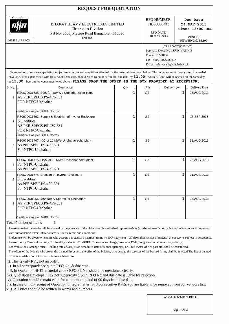
REQUEST FOR QUOTATION
Sl No. Description Qty Unit Delivery qty Delivery Date
1
PS0679031685 BOS for 10MWp Unchahar solar plant
AS PER SPECS.PS-439-831FOR NTPC-Unchahar
Certificate as per BHEL Norms
1 ST 1 06.AUG.2013
2
PS0679031693 Supply & Establish of Inveter Enclosure
& FacilitiesAS PER SPECS.PS-439-831FOR NTPC-Unchahar
Certificate as per BHEL Norms
1 ST 1 15.SEP.2013
3
PS0679031707 I&C of 10 MWp Unchahar solar plant
As PER SPEC PS-439-831For NTPC-Unchahar.
1 ST 1 21.AUG.2013
4
PS0679031715 O&M of 10 MWp Unchahar solar plant
For NTPC-UnchaharAs PER SPEC PS-439-831
1 ST 1 25.AUG.2013
5
PS0679031774 Erection of Inverter Enclosure
& FacilitiesAs PER SPEC PS-439-831For NTPC-Unchahar
1 ST 1 21.AUG.2013
6
PS0679031855 Mandatory Spares for Unchahar
AS PER SPECS.PS-439-831FOR NTPC-Unchahar.
Certificate as per BHEL Norms
1 ST 1 06.AUG.2013
Total Number of Items - 6
Please note that the tender will be opened in the presence of the bidders or his authorised representatives (maximum two per organisation) who choose to be present
with authorisation letters. Refer annexure for the terms and conditions.
Preference will be given to vendors who accepts our standard payment terms i.e.100% payment - 30 days after receipt of material at our works subject to acceptance.
Please specify Terms of delivery, Excise duty, sales tax, Ex-BHEL, Ex-works surcharge, Insurance,P&F, Freight and other taxes very clearly .
For evaluation,exchange rate(TT selling rate of SBI) as on scheduled date of tender opening (Part-I bid incase of two part bid) shall be considered.
The offers of the bidders who are on the banned list as also the offer of the bidders, who engage the services of the banned firms, shall be rejected.The list of banned
firms is available on BHEL web site www.bhel.com
i). This is only RFQ not an order. ii). In all correspondence quote RFQ No. & due date. iii). In Quotation BHEL material code / RFQ Sl. No. should be mentioned clearly. iv). Quotation Envelope / Fax not superscribed with RFQ No.and due date is liable for rejection. v). Quotation should remain valid for a minimum peiod of 90 days from due date.vi). In case of non-receipt of Quotation or regret letter for 3 consecutive RFQs you are liable to be removed from our vendors list.vii). All Prices should be written in words and numbers.
MMI:PU:RF:003
BHARAT HEAVY ELECTRICALS LIMITEDElectronics Division
PB No. 2606, Mysore Road Bangalore - 560026INDIA
For and On behalf of BHEL.
Page 1 OF 2
RFQ NUMBER: HBS0000443
RFQ DATE : 10.MAY.2013
Please submit your lowest quotation subject to our terms and conditions attached for the material mentioned below. The quotation must be enclosed in a sealed
envelope / Fax superscribed with RFQ no.and due date, should reach us on or before the due date by 13.00 hours IST and will be opened on the same day
at 13.30 hours at the venue mentioned above. PLEASE DROP THE OFFER IN THE BOX PROVIDED AT RECEPTION.
PURCHASE FILE COPY
Due Date24.MAY.2013
Time: 13:00 HRS
VENUE :NEW ENGG. BLDG
(for all correspondence)
Purchase Executive : SRINIVAS H B
Phone : 26998452
Fax : 00918026989217
E-mail: [email protected]
REQUEST FOR QUOTATION
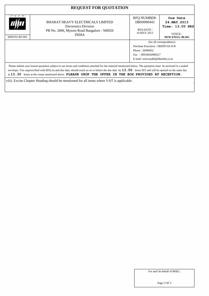
viii). Excise Chapter Heading should be mentioned for all items where VAT is applicable .
Vendors list to whom RFQ has been sent:1. BHEL, Electronics Division (X563699) - 6400029067
MMI:PU:RF:003
BHARAT HEAVY ELECTRICALS LIMITEDElectronics Division
PB No. 2606, Mysore Road Bangalore - 560026INDIA
For and On behalf of BHEL.
Page 2 OF 2
RFQ NUMBER: HBS0000443
RFQ DATE : 10.MAY.2013
Please submit your lowest quotation subject to our terms and conditions attached for the material mentioned below. The quotation must be enclosed in a sealed
envelope / Fax superscribed with RFQ no.and due date, should reach us on or before the due date by 13.00 hours IST and will be opened on the same day
at 13.30 hours at the venue mentioned above. PLEASE DROP THE OFFER IN THE BOX PROVIDED AT RECEPTION.
PURCHASE FILE COPY
Due Date24.MAY.2013
Time: 13:00 HRS
VENUE :NEW ENGG. BLDG
(for all correspondence)
Purchase Executive : SRINIVAS H B
Phone : 26998452
Fax : 00918026989217
E-mail: [email protected]
1.0 PRE-QUALIFICATION CRITERIA FOR EVALUATION:
The EPC contractor shall meet the qualifying requirement stipulated as below:
1.1 AA) The bidder shall be manufacturer of any one of the following major electrical
equipment of solar PV power plant in India along with established service facilities in
India for a minimum period of 1 year as on date of bid opening viz,
i. Grid connected PV inverter (Min. 500 KW)
ii. MV switchgear (11KV and above)
iii. Power Transformer (Min. 11 KV and Min. 1 MVA)
AND
BB) The bidder shall have executed electrical, civil and mechanical package of a single,
minimum of 3 MWp SPV power plant within India. Bidder shall be an executor and not a
project developer. Bidder shall furnish the details of project executed such as a) Project
location & details b) Customer details c) Satisfactory performance certificate of the
installed plant issued by customer.
OR
1.2 AA) Bidder shall have executed a single, minimum of 3MWp grid connected SPV plant
within India on EPC basis and shall submit proof of such execution from the end user
detailing the start date of the project, end date of the project and with all the details of
the scope undertaken under this EPC.
AND
BB) The bidder shall have a firm tie-up in the form of JV/MoU/Working arrangement
with any of the major Indian equipment manufacturer as per 1.1 AA (i),(ii)and (iii)
above with the commitment of delivery and also support for completion of scope of
work as per tender specification.
2.0 OTHER INFORMATION:
The bidder shall submit the following details along with the bid:
1) Audited balance sheets for last three years
2) Number of persons employed (Category wise: Professional, skilled, unskilled etc.)
TPH
P1234
5
6
7891
P123456
7
PP
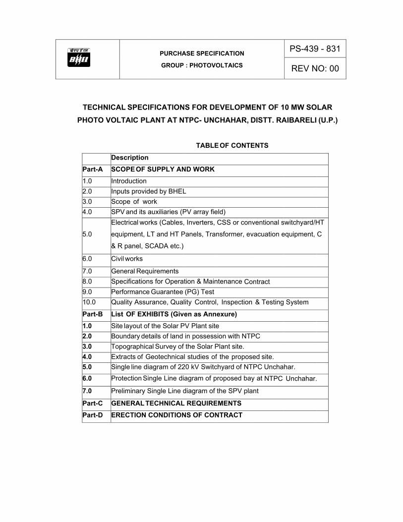
TECHNICAHOTO VO
DePart-A SC1.0 Int2.0 In3.0 Sc4.0 SP
5.0
El
eq
&
6.0 Ci
7.0 Ge8.0 Sp9.0 Pe10.0 Qu
Part-B Li1.0 Si2.0 Bo3.0 To4.0 Ex5.0 Si
6.0 Pr
7.0 Pr
Part-C GEPart-D ER
AL SPECIFLTAIC PLA
escription
COPE OF Stroduction puts providcope of woPV and its aectrical wor
quipment, L
R panel, SC
ivil works
eneral Requpecificationserformance uality Assur
st OF EXHte layout of oundary detopographicaxtracts of Gngle line dia
rotection Sin
reliminary S
ENERAL TERECTION C
PURCHA
GROUP
FICATIONANT AT N
SUPPLY AN
ed by BHELork auxiliaries (Prks (Cables,
T and HT P
CADA etc.)
uirements s for OperaGuaranteerance, Qua
HIBITS (Givthe Solar P
tails of landal Survey ofeotechnicaagram of 22
ngle Line di
Single Line d
ECHNICALCONDITION
ASE SPECIF
: PHOTOVO
NS FOR DENTPC- UNC
TABLE
ND WORK
L
PV array fie, Inverters,
Panels, Tran
tion & Main(PG) Testlity Control
ven as AnnePV Plant site
in possessf the Solar Pl studies of
20 kV Switc
agram of p
diagram of t
L REQUIRENS OF CON
FICATION
OLTAICS
EVELOPMCHAHAR,
E OF CONT
eld) CSS or con
nsformer, ev
ntenance Co
, Inspection
exure)
eion with NT
Plant site. f the proposchyard of NT
roposed ba
the SPV pla
EMENTSNTRACT
MENT OF 1DISTT. RA
ENTS
nventional s
vacuation e
ontract
n & Testing
TPC
sed site. TPC Uncha
ay at NTPC
ant
PS-439
REV N
0 MW SOAIBARELI
switchyard/H
equipment,
System
har.
Unchahar.
9 - 831
NO: 00
LAR (U.P.)
HT
C

Part-A
SCOPE OF SUPPLY AND WORK

1.0 INTRODUCTION: 1.1 PROJECT INTRODUCTION: BHEL-EDN Bangalore is setting up a 10MWp grid-connected SPV power plant at Unchahar
village for NTPC. This technical specification provides details of supply of materials to site,
safe storage of materials at site, receipt, unloading and safe storage of BHEL supplied
materials, erection, installation, system integration, pre-commissioning checks, commissioning
of the entire plant. Contractor is also responsible for the associated engineering activity in
execution of this 10 MW plant. This specification defines the scope of EPC (Engineering,
procurement and Construction). BHEL based on site survey has collected certain site pertinent
data, the same are attached along with this specification.
1.2 PROJECT INFORMATION: The proposed Solar Photo Voltaic plant shall be located in the vicinity of Feroze Gandhi
Unchahar Power Station (FGUPS) of NTPC. FGUPS is located at Unchahar, Raebareli district
of Uttar Pradesh. It is located at a distance of approx. 3km from Unchahar town on
Allahabad - Raebareli BG section of Northern Railway. It is situated 35km from Raebareli,
120 km from Lucknow and 80km from Allahabad on Lucknow- Allahabad Highway.
Available land for the construction: Approximately 44 acre of land is available for the plant and other facilities. Land is under
possession of NTPC. Site photos attached for reference. If Contractor feels essential, a quick
visit may be made to site.
2.0 INPUTS PROVIDED BY BHEL: 1. Land details and topographical Survey for the proposed area
2. Brief Geotechnical investigation Report of proposed site.
3. Preliminary Single Line Diagram of the plant
4. Preliminary PV array layout showing the distribution of inverter rooms for locating
inverters and CSS/conventional switchyards.
5. Site Photos
3.0 SCOPE OF WORK: Design, engineering, supply, packing and forwarding, transportation, unloading, storage,
installation and commissioning of 10 MWp Solar PV based power project (the required solar
PV modules will be supplied by BHEL to site, Unloading of PV modules and safe storage is in
contractor’s scope) and interconnection to 220 kV switchyard including drawal of 33KV line
through Underground AND/OR overhead path on turnkey basis at NTPC- Unchahar.
Contractor shall provide comprehensive operation & maintenance of the plant for a period of
one year from the date of successful completion of trial run. Contractor shall post adequate
number of operators for O & M activity at site. All the required spares shall be stocked so as to
have trouble-free operation. O & M shall include:
a) trained and licensed (for HT and LT operation) operators to be posted at site.
b) Module water washing shall be strictly carried out at least once in 15 days. If the site
condition demands, higher frequency of cleaning, the same shall be implemented.
c) Maintenance of all the transformers (33kV and 220 kV) including oil filtration once a
year and maintenance of 33KV transmission line OR underground line including the
associated assembly.
d) Collection of daily, monthly and annual data of the plant from SCADA and carrying out
remedial action for any fault in the plant so that generation is not affected.
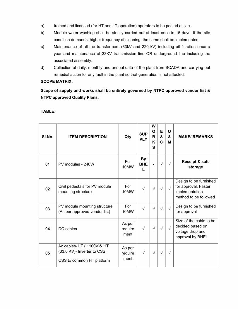
SCOPE MATRIX:
Scope of supply and works shall be entirely governed by NTPC approved vendor list & NTPC approved Quality Plans. TABLE:
Sl.No. ITEM DESCRIPTION Qty SUPPLY
WORKS
E&C
O&M
MAKE/ REMARKS
01 PV modules - 240W For
10MW
By BHE
L - √ √ Receipt & safe
storage
02 Civil pedestals for PV module mounting structure
For 10MW √ √ √ √
Design to be furnished for approval. Faster implementation method to be followed
03 PV module mounting structure (As per approved vendor list)
For 10MW √ √ √ √ Design to be furnished
for approval
04 DC cables As per requirement
√ √ √ √
Size of the cable to be decided based on voltage drop and approval by BHEL
05
Ac cables- LT ( 1100V)& HT (33.0 KV)- Inverter to CSS,
CSS to common HT platform
As per requirement
√ √ √ √
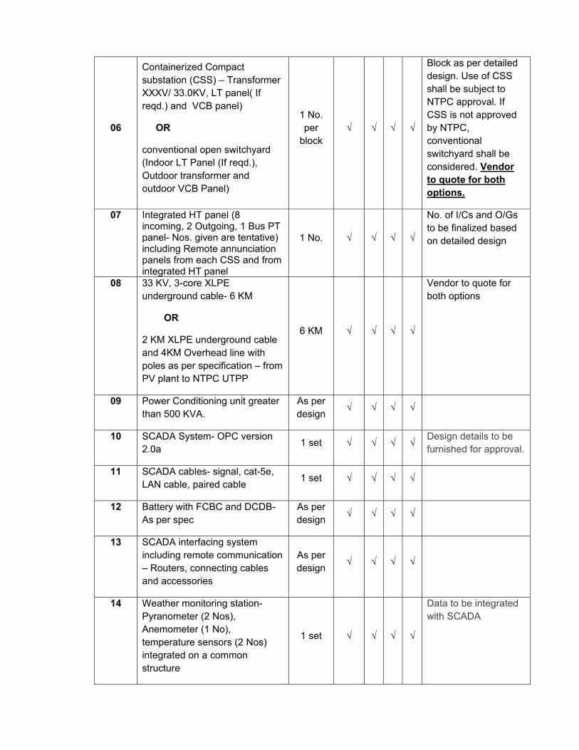
06
Containerized Compact substation (CSS) – Transformer XXXV/ 33.0KV, LT panel( If reqd.) and VCB panel)
OR
conventional open switchyard (Indoor LT Panel (If reqd.), Outdoor transformer and outdoor VCB Panel)
1 No. per
block √ √ √ √
Block as per detailed design. Use of CSS shall be subject to NTPC approval. If CSS is not approved by NTPC, conventional switchyard shall be considered. Vendor to quote for both options.
07 Integrated HT panel (8 incoming, 2 Outgoing, 1 Bus PT panel- Nos. given are tentative) including Remote annunciation panels from each CSS and from integrated HT panel
1 No. √ √ √ √
No. of I/Cs and O/Gs to be finalized based on detailed design
08 33 KV, 3-core XLPE underground cable- 6 KM
OR
2 KM XLPE underground cable and 4KM Overhead line with poles as per specification – from PV plant to NTPC UTPP
6 KM √ √ √ √
Vendor to quote for both options
09 Power Conditioning unit greater than 500 KVA.
As per design
√ √ √ √
10 SCADA System- OPC version 2.0a 1 set √ √ √ √ Design details to be
furnished for approval.
11 SCADA cables- signal, cat-5e, LAN cable, paired cable 1 set √ √ √ √
12 Battery with FCBC and DCDB- As per spec
As per design √ √ √ √
13 SCADA interfacing system including remote communication – Routers, connecting cables and accessories
As per design
√ √ √ √
14 Weather monitoring station- Pyranometer (2 Nos), Anemometer (1 No), temperature sensors (2 Nos) integrated on a common structure
1 set √ √ √ √
Data to be integrated with SCADA
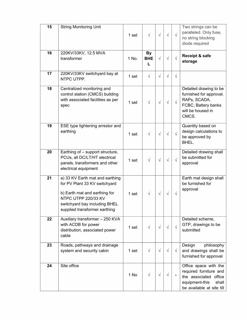
15 String Monitoring Unit
1 set √ √ √ √
Two strings can be paralleled. Only fuse, no string blocking diode required
16 220KV/33KV, 12.5 MVA transformer 1 No.
By BHE
L √ √ √ Receipt & safe
storage
17 220KV/33KV switchyard bay at NTPC UTPP. 1 set √ √ √ √
18 Centralized monitoring and control station (CMCS) building with associated facilities as per spec 1 set √ √ √ √
Detailed drawing to be furnished for approval. RAPs, SCADA, FCBC, Battery banks will be housed in CMCS.
19 ESE type lightening arrestor and earthing 1 set √ √ √ √
Quantity based on design calculations to be approved by BHEL.
20 Earthing of – support structure, PCUs, all DC/LT/HT electrical panels, transformers and other electrical equipment
1 set √ √ √ √
Detailed drawing shall be submitted for approval
21 a) 33 KV Earth mat and earthing for PV Plant 33 KV switchyard
b) Earth mat and earthing for NTPC UTPP 220/33 KV switchyard bay including BHEL supplied transformer earthing
1 set √ √ √ √
Earth mat design shall be furnished for approval
22 Auxiliary transformer – 250 KVA with ACDB for power distribution, associated power cable
1 set √ √ √ √
Detailed scheme, GTP, drawings to be submitted
23 Roads, pathways and drainage system and security cabin 1 set √ √ √ √
Design philosophy and drawings shall be furnished for approval
24 Site office
1 No √ √ √ -
Office space with the required furniture and the associated office equipment-this shall be available at site till
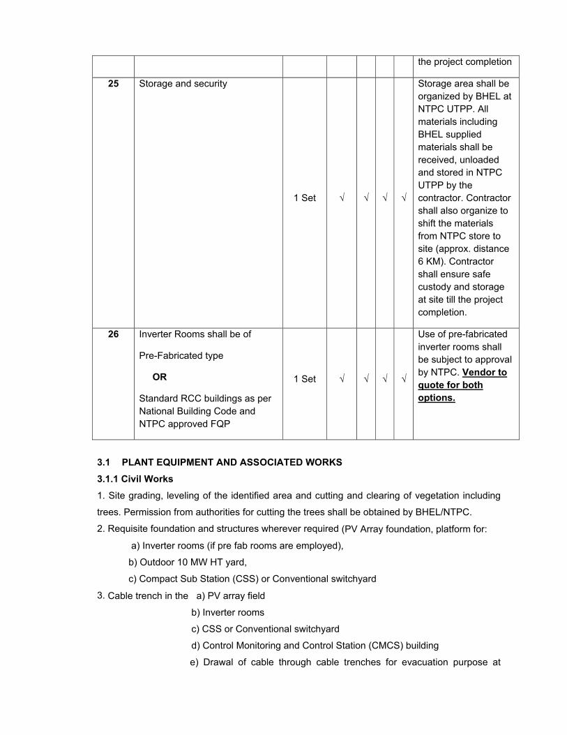
3.1 PLANT EQUIPMENT AND ASSOCIATED WORKS
3.1.1 Civil Works 1. Site grading, leveling of the identified area and cutting and clearing of vegetation including
trees. Permission from authorities for cutting the trees shall be obtained by BHEL/NTPC.
2. Requisite foundation and structures wherever required (PV Array foundation, platform for:
a) Inverter rooms (if pre fab rooms are employed),
b) Outdoor 10 MW HT yard,
c) Compact Sub Station (CSS) or Conventional switchyard
3. Cable trench in the a) PV array field
b) Inverter rooms
c) CSS or Conventional switchyard
d) Control Monitoring and Control Station (CMCS) building
e) Drawal of cable through cable trenches for evacuation purpose at
the project completion
25 Storage and security
1 Set √ √ √ √
Storage area shall be organized by BHEL at NTPC UTPP. All materials including BHEL supplied materials shall be received, unloaded and stored in NTPC UTPP by the contractor. Contractor shall also organize to shift the materials from NTPC store to site (approx. distance 6 KM). Contractor shall ensure safe custody and storage at site till the project completion.
26 Inverter Rooms shall be of
Pre-Fabricated type
OR
Standard RCC buildings as per National Building Code and NTPC approved FQP
1 Set √ √ √ √
Use of pre-fabricated inverter rooms shall be subject to approval by NTPC. Vendor to quote for both options.
33KV yard, 220KV yard and along the route wherever required.
4. Main and service roads, with suitable drainage arrangements wherever necessary as per
BHEL/NTPC approved drawings.
5. Construction of CMCS and RCC buildings for inverter rooms (if employed instead of pre fab
inverter rooms) and other facilities.
6. Fencing of 33 kV Switchyard.
7. Civil structure for water storage tanks, PV module water washing system.
3.1.2 Solar PV Plant The system shall consist of (but not limited to) following equipment:
(a) Module Mounting structures (MMS)
(b) String Monitoring Unit (SMU) system
(c) Cables and hardware
(d) Power conditioning unit (PCU) / Grid connected Inverter
(e) Compact Sub-station (CSS) (LT Panel (if reqd.), Transformer and VCB Panel) or
conventional switchyard (indoor LT panel (if reqd.), outdoor transformer and outdoor
VCB Panel) / HT equipment.
(f) 220kV/33 kV switchyard construction excluding supply of 220kV/33kV, 12.5 MVA
Transformer (BHEL will supply this transformer) close to Unchahar Thermal power plant
(UTPP) switchyard. All other works including gantry in the scope of contractor.
(g) C & R Panel for 220kV switchyard (To be located in the NTPC UTPP control room).
(h) Metering cubicle with ABT energy meters (main and check meters) at 33 kV switch yard
in the PV plant and 220 kV/33 kV switch yard at UTPP.
(i) SCADA
(j) Remote Annunciation Panel (RAP) for control and monitoring of all the HT breakers in
the plant. RAP shall be located in CMCS building.
(k) DC Battery bank (Tubular Gel type) with FCBC for 33kV switchyard in SPV plant to be
supplied and commissioned.
(l) AC Distribution boxes and DC distribution boxes
(m) Earthing kits & Earth mat
(n) Lightning arrestors in Solar array and HT yards
(o) Tool Kits for maintenance along with personal protective equipment
(p) Weather monitoring equipment
(q) Mandatory spares
(r) Furniture
(s) Illumination system for the plant including array, control room, switchyard and plant
periphery
(t). Consumable for Modules washing and Office stationary during O & M.
3.1.3 Grid interfacing, including all equipment required for the same such as transformers,
breakers, isolators, lightning arrestor, panels, protection equipment, cables, conductors,
earthing of transformer and SPV Panel yard etc. as per statutory requirements and comply to
CERC Grid code.
3.1.4 Routing, planning and Construction etc. of towers or cable trenches as required for
facilitating evacuation of Power from SPV plant through 33 kV transmission
lines/underground cable. Cable laying, Overhead line drawal as per relevant IS norms shall be
in contractor’s scope. Other works not specified above but required as per site for evacuation
shall be under the scope of the successful contractor. “Right of Way” shall be in NTPC’s scope.
3.1.5 Erection & Commissioning of 33/220 kV 12.5 MVA transformer and its termination to
220kV switchyard of NTPC Unchahar Station. The necessary civil works involving foundations
for transformers, circuit breakers, isolators and other equipment, and other works as required
at site, for the completion of the job shall be under the scope of the successful contractor.
3.1.6 Metering of outgoing energy at the 33 kV outgoing feeder and 220 kV feeder on HV side
of transformer is in the scope of contractor.
3.1.7 Design & construction of Control Monitoring & Control System (CMCS) to house
control panels, protection panels, GPS time synchronization system for remote monitoring &
control the plant etc, and inverter room to house the inverters. 220kV and 33kV (yard end)
control and protection panels shall be located in the existing switchyard control room and
control panels for 33kV breakers (at solar plant end) shall be located in CMCS room.
3.1.8 Fire protection and fire fighting equipment with state licensed agency.
3.1.9 Arrangement of water and auxiliary power supply during construction and O&M period
shall be done by the contractor. Contractor shall dig 3 Nos Bore wells and provide with pumps
and piping.
3.1.10 Supply & providing suitable illumination for the proposed SPV plant, evacuation
system including CMCS, CSS, Inverter rooms and other facilities.
3.1.11 Extending the Status of Analog and Digital inputs from 220kV bay to existing RTU.
Necessary Cable and cabling shall be in contractor's scope.
3.1.12 Modification of control & protection schemes of existing Transfer Bus Bay due to the
addition of 220kV/33kV Transformer Bay shall be in contractor's scope.
3.1.13 Providing Portable engineering workstation pre-loaded with relay configuration software,
EM software.
3.1.14 Providing drainage system for the plant and connection to discharge system as per
pollution norms wherever applicable.
3.2 ENGINEERING DATA & DRAWINGS
3.2.1 Engineering drawing, data etc including calculations shall be prepared by the contractor
and got approved from BHEL/NTPC before commencement of the project.
3.2.2 Successful contractor shall furnish operation and maintenance manual in six (06) sets
prior to commencement of warranty period in hard as well as soft form.
3.3 TRAINING OF EMPLOYERS PERSONNEL
The contractor shall provide training to at least four personnel of B H E L /NTPC for a
minimum period of 10 days at his works and at site for erection, testing, commissioning
and O & M. Expenses towards travel, stay, lodging, and boarding and other expenses for the
personnel shall be borne by BHEL/NTPC.
3.4 TERMINAL POINTS & EXCLUSIONS
The terminal point under the scope of this assignment shall be interfacing upto 220 kV
existing busbars of switchyard of NTPC Unchahar. Supply of PV modules and supply of 220/33
KV, 12.5 MVA transformer shall be in BHEL’s scope.
The scope of the contractor shall be deemed to include all such items which although are
not specifically mentioned in the bid documents and/or in contractor’s proposal but are
needed to make the system complete in all respects for its safe, reliable, efficient and
trouble free operation and the same shall be furnished and erected unless otherwise
specifically excluded as per this Section.
4.0 SPV and Its Accessories
4.1 SPV Module
SPV modules of required capacity shall be supplied by BHEL. Drawings of module shall be
provided to the Contractor for use in design of array layout and module mounting structure
design.
4.1.1 MODULE MOUNTING STRUCTURE
The design of module mounting structure shall be provided by BHEL. In case if the Contractor
proposes to use any other design of structure, BHEL shall decide based on the economics and
technical strength of the design.
1. Modules shall be mounted on a non-corrosive support structures
2. All the Panels shall have provision to adjust at three angular positions at approximate
interval of 15 deg angular difference. The locking arrangement for adjusting the angle of
module shall be accessible from the ground. Contractors to bring out the season wise angles in
the data sheet.
3. The base columns shall be made with reinforced cement concrete. The minimum
clearance between the lower edge of the modules and the developed ground level shall be 500
mm.
Contractor may propose other type of foundation depending on soil conditions, geographical
condition, regional wind speed, bearing capacity, slope stability etc. In such case, the
detailed foundation design should be proof checked by IIT/NIT and have to be got approved
from BHEL/NTPC before actual start of work.
Foundation design shall be Pile with Pile Cap, Ramming of structure legs, Ramming Re-bars
so as to suit the site requirements based on the soil conditions, Subject to deign proof check
as above. Irrespective of type of foundation employed by the contractor, Contractor has to
organize multiple machineries, tools, tackles and patterns so as to have minimum throughput
of 500kW. Mobile Mini batching plant shall be organized by the contractor for concrete mixing.
Volumetric mixing at site is not permitted.
4. In case offered support structure is of MS type then, the frames and leg assemblies of the
array structures shall be made of MS hot dip galvanized. Galvanization coating shall as per
IS 4759 or equivalent standards.
5. All fasteners shall be of Stainless steel - SS 304. Nut & bolts, supporting structures
including module Mounting Structures shall have to be adequately protected against all
climatic condition.
4.2 INSTRUMENTS FOR METEOROLOGICAL MEASUREMENTS. Contractor shall provide following measuring instruments with all necessary software &
hardware required to make it compatible with SCADA.
4.2.1 Pyranometer :
Contractor shall provide at least two (02) pyranometer for measuring incident global solar
radiation. The specification is as follows:
1. Spectral Response- 0.31 to 2.8 micron.
2. Sensitivity-9 micro-volt/w/m2 3. Time response(95%): Max 15 s 4. Non linearity: ±0.5% 5. Temperature Response: ±2% 6. Temperature Response= Max ±2% 7. Tilt error: ±0.5%.
8. Zero offset thermal radiation: ±7 w/m2
9. Zero offset temperature change ±2 w/m2 10. Operating temperature range: - 40 deg to +80 deg. 11. Uncertainty(95% confidence Level): Hourly- Max-3% Daily- Max-2% 12. Non stability: Max ±0.8% 13. Resolution: Min + / - 1 W/m2 14. Input Power for Instrument & Peripherals: 230 VAC (If required) 15. Output Signal: Analogue form which is compatible with the data
Each instrument shall be supplied with necessary cables. Calibration certificate with calibration traceability to World Radiation Reference (WRR) or World Radiation Centre (WRC) shall be furnished along with the equipment. The signal cable length shall not exceed 20m. Contractor shall provide Instrument manual in hard and soft form. 4.2.2 Thermometer : Contractor shall also provide two Nos of RTD type / semiconductor type ambient temperature measuring instrument at suitable place in PV array. Instrument shall have a range of 0o C to 80oC. 4.2.3 Anemometer : Contractor shall provide anemometer on tubular type made up of hot dipped Galvanized iron. Velocity range- Upto 25 m/s, accuracy limit of 0.2 m/s upto 10 m/sec. All the above sensors (Cl. 4.2.1 to 4.2.3) shall have valid calibration certificates which should be produced within one month after the installation. Note : The above sensors (Cl. 4.2.1 to 4.2.3) shall be erected as a Single weather monitoring unit. This unit shall provide data signal so as to integrate to SCADA without loss of accuracy. 4.3 POWER CONDITIONING UNIT / GRID CONNECTED INVERTER Power Conditioning Unit (PCU) consist of an electronic Inverter along with associated control,
protection and data logging devices. The system shall incorporate a uni-directional inverter
designed to supply the AC power to the grid at load end conforming to IEC 61727 or equivalent
standard. The power conditioning unit shall adjust the voltage & frequency levels to suit the
Grid.
Rating of each PCU shall be greater than 500 kVA and the combined kVA rating of all
PCUs shall not be less than 10000 kVA at standard temperature.
All three phases shall be supervised with respect to rise/fall in programmable threshold
values of frequency. PCU must have provision to be isolated from grid through Air Circuit
Breaker.
4.3.1 General Requirements
a. The efficiency of the PCU shall be equal to or more than 97 % at 75% load as per IEC
61683 or equivalent standard. The contractor shall specify the conversion efficiency at
different load say 25%, 50%, 75% and 100% in his offer.
b. The PCU shall have internal protection arrangement against any sustained fault in the
feeder line and against lightning in the feeder line.
c. The PCU shall have the required protection arrangements against earth leakage faults.
d. Specifically, the PCU should be three phase power conditioning unit using static solid
state components. DC lines shall have suitably rated isolators to allow safe start up and shut
down of the system. DC lines side of PCU should have isolator of suitable rating.
e. Each Sub-Array Junction Box/SMU will have suitably rated fuse with suitable rating for its
connecting.
f. Electrical surge protection shall be provided with surge protection device (SPD). SPD
shall consist of three Metal Oxide Varistor (MOV) type arrestors connected from positive and
negative to earth with inbuilt fuse or thermal disconnector. During earth fault condition SPD
shall safely disconnect the healthy system.
g. The PCU should be suitably designed for parallel operation. Each solid state electronic
device shall have to be protected to ensure long life of the inverter as well as smooth
functioning of the inverter. As 2 Nos of Inverters are taken through a 3 winding transformer
(double LV winding), PCU shall be suitable to work with such combination.
h. The PCU shall have anti islanding protection.
i. The PCU must have the feature to work in tandem with other similar PCU’s and be
able to be successively switched “ON” and “OFF” automatically based on solar radiation
variations during the day.
j. The system shall tend to balance unequal phase voltage (with 3-phase systems) with
reference to the red phase (line-1).
k. The PCU front panel shall be provided with a display (LCD or equivalent) of all important
parameter such as DC input voltage, DC input current, AC input voltage, AC input current,
AC output power, frequency etc.
If the contractor is not able to provide PCU with display, the same has to be made available
at SCADA.
l. Nuts & bolts and the PCU enclosure shall have to be adequately protected taking into
consideration the atmosphere and weather prevailing in the area.
m. The PCU shall include appropriate self protective and self diagnostic feature to protect
itself and the PV array from damage in the event of PCU component failure or from
parameters beyond the PCU’s safe operating range due to internal or external causes. The
self-protective features shall not allow signals from the PCU front panel to cause the PCU to

be operated in a manner which may be unsafe or damaging.
Faults due to malfunctioning within the PCU, including commutation failure, shall be cleared
by the PCU protective devices.
Control and read-out should be provided on an indicating panel integral to the Inverter. Display
should be simple and self explanatory display to show all the relevant parameter relating to
PCU operational data and fault condition in form of front Panel meters / LED’s or two line
LCD Display.
MODES OF PCU
• STANDBY MODE:
The control system shall continuously monitor the output of the solar power plant until pre-
set value is exceeded & that value to be indicated in datasheet.
• BASIC SYSTEM OPERATION (FULL AUTO MODE): The system shall automatically ‘wake up’ in the morning and begin to export power provided
there is sufficient solar energy and the grid voltage and frequency is in range.
• MAXIMUM POWER POINT TRACKER (MPPT): MPPT control algorithm shall adjust the voltage of the SPV array to optimise solar energy
fed into the grid.
• SLEEP MODE
Automatic ‘sleep’ mode shall be provided so that unnecessary losses are minimized at night.
Contractor to provide threshold dc voltage of the inverter to enter in sleep mode and back
to standby mode in the technical datasheet
The power conditioner must also automatically re-enter standby mode when threshold of
standby mode reached.
4.3.2 Maximum Power Tracking
Maximum power point tracker shall be integrated in the power conditioner unit to maximize
energy drawn from the Solar PV array. The MPPT should be microprocessor based to
minimize power losses. The details of working mechanism of MPPT shall be mentioned by the
contractor in
his offer. The MPPT must have provision for constant voltage operation. .Pan details of BHEL
PV module attached base on this contractor shall decide the number of PV modules to be
connected in series.
4.3.3 Central Inverter The inverter output shall always follow the grid in terms of voltage and frequency. This shall
be achieved by sensing the grid voltage and phase and feeding this information to the
feedback loop of the inverter. Thus control variable then controls the output voltage and
frequency of the inverter, so that inverter is always synchronized with the grid. The inverter
shall use self- commutated device.
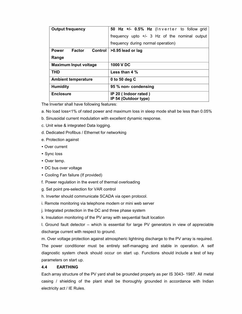
Output frequency 50 Hz +/- 0.5% Hz (I n v e r t e r to follow grid
frequency upto +/- 3 Hz of the nominal output
frequency during normal operation)
Power Factor Control Range
>0.95 lead or lag
Maximum Input voltage 1000 V DC
THD Less than 4 %
Ambient temperature 0 to 50 deg C
Humidity 95 % non- condensing
Enclosure IP 20 ( Indoor rated ) IP 54 (Outdoor type)
The Inverter shall have following features:
a. No load loss<1% of rated power and maximum loss in sleep mode shall be less than 0.05%
b. Sinusoidal current modulation with excellent dynamic response.
c. Unit wise & integrated Data logging.
d. Dedicated Profibus / Ethernet for networking
e. Protection against
• Over current
• Sync loss
• Over temp.
• DC bus over voltage
• Cooling Fan failure (If provided)
f. Power regulation in the event of thermal overloading
g. Set point pre-selection for VAR control
h. Inverter should communicate SCADA via open protocol.
i. Remote monitoring via telephone modem or mini web server
j. Integrated protection in the DC and three phase system
k. Insulation monitoring of the PV array with sequential fault location
l. Ground fault detector – which is essential for large PV generators in view of appreciable
discharge current with respect to ground.
m. Over voltage protection against atmospheric lightning discharge to the PV array is required.
The power conditioner must be entirely self-managing and stable in operation. A self
diagnostic system check should occur on start up. Functions should include a test of key
parameters on start up.
4.4 EARTHING
Each array structure of the PV yard shall be grounded properly as per IS 3043- 1987. All metal
casing / shielding of the plant shall be thoroughly grounded in accordance with Indian
electricity act / IE Rules.

4.5 Control, Automation and Data Acquisition System (SCADA) The complete Solar PV plant shall be integrated with SCADA which should communicate
with all the inverters and combiner box (SMU) and displaying parameters as mentioned below.
SCADA shall also have provision to control turning ON and OFF of any inverter of the grid
connected Solar PV plant.
SCADA shall provide instantaneous data of following parameters.
1. Power at 33 kV terminal
2. Ambient temperature
3. Wind Speed
4. AC and DC side Power of each inverter
5. Solar irradiation/isolation
6. Voltage of the HT Side
7. Current and voltage of each sub-array/string.
8. Any other parameter considered necessary by supplier based on current prudent practice.
SCADA shall store the daily energy produced by the plant, monthly energy and the annual
energy. Further SCADA shall also display the Performance Ratio (PR) of the plant. All the
trend and cumulative graphs shall be able to view and store. Also all the events including
outages and faults shall be logged and stored with time and date stamped. SCADA should
also have provision for offline viewing of daily, monthly and annual average of the above
parameters
SCADA shall provide 15 minute interval daily, monthly and annual average of following
parameters:
1. Exported Energy
2. Energy of each inverter
The SCADA shall have the feature to be integrated with the Network system as well as
remotely via the web using either a standard modem or a GSM/WIFI modem. The contractor
shall provide compatible software and hardware so that data can be transmitted via standard
modem.
Fixed and variable Charges (during O&M period) payable to the telecom company shall be
borne by the contractor.
'The SCADA shall be OPC version 2.0a compliant and implement a OPC-DA 2.0a server as
per the specification of OPC Foundation. All data should be accessible through this OPC
server.'
SCADA shall be provided with a reliable power supply along with a backup supply for at
least one hour to cater to outage of grid.
4.5.1 STRING MONITORING UNIT (SMU) Combiner box shall house string monitors which shall give operational status of each sub

array/string by current and/or power and shares the information with SCADA. Foot print of PV
array showing the location of each SMU shall be displayed as a screen shot on the SCADA
screen so that operator can identify the faulty SMU and the string from the SCADA screen.
The enclosure shall be Flammability Fire Retardant with Self-Extinguishing property and free
from Halogen. It
should be UV resistant in accordance with UL 746C suitable for outdoor application. The
mechanical impact resistance of IK 07 or better as per IEC 62262 or equivalent standard.
The enclosure rating shall be IP65 or better.
The control PCB housed in each SMU shall be rugged and proven for reliable performance.
Each SMU shall be provided with properly rated Surge Protection Device (SPD). Either
precision shunt or Hall sensor can be employed for sensing of string. Maximum of 2 (two) PV
strings can be paralleled per channel of SMU for current measurement. SMU shall measure
string voltage and shall be displayed in SCADA as real time parameter. SMU shall also provide
the SPD status on the SCADA screen. Contractor shall arrange to draw data communication
cables (Like RS-485), from each SMU to SCADA. Integrated SCADA shall be provided for the
entire plant which includes SMU data and weather station parameters.
5.0 Technical Specification of Electrical Work
5.1 The power evacuation system shall comprise of at least four (04), (as per BHEL SLD
– 8 transformer) transformers at different bay feeding 33 kV bus. In addition, the substation
shall also have one (01) feeder bay to evacuate power.
The 33 kV substation at Solar power plant shall be connected to 220 kV buses of
switchyard through 33/220 kV transformer as indicated in the drawing (Exhibit-6 of this
document).
Contractor shall submit following drawings to BHEL for approval.
1. SPV array and cable layout. 2. Module foundation 3. Main & service road with general drainage 4. ACDB Layout, If applicable 5. 33 kV Switchyard 6. Power Evacuation system 7. Switchgear related to 33/220 kV transformer8. Earthing
5.1.1 COMPACT SUB-STATION (CSS) or conventional switchyard: Each PV quadrant shall have a pre-fabricated, Pre-wired Compact Sub-station or
conventional switchyard. Use of Compact Substation will be subject to NTPC approval. This
unit is an interface between Inverter power output to PV plant switchyard.
The enclosure for compact substation shall be made of stainless steel or Aluminum-Zinc.
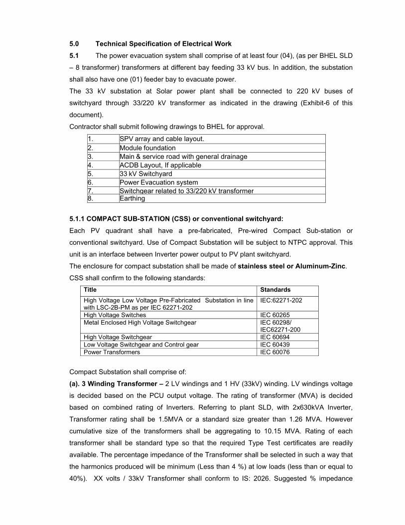
CSS shall confirm to the following standards:
Title Standards High Voltage Low Voltage Pre-Fabricated Substation in line with LSC-2B-PM as per IEC 62271-202
IEC:62271-202
High Voltage Switches IEC 60265 Metal Enclosed High Voltage Switchgear IEC 60298/
IEC62271-200 High Voltage Switchgear IEC 60694 Low Voltage Switchgear and Control gear IEC 60439 Power Transformers IEC 60076
Compact Substation shall comprise of:
(a). 3 Winding Transformer – 2 LV windings and 1 HV (33kV) winding. LV windings voltage
is decided based on the PCU output voltage. The rating of transformer (MVA) is decided
based on combined rating of Inverters. Referring to plant SLD, with 2x630kVA Inverter,
Transformer rating shall be 1.5MVA or a standard size greater than 1.26 MVA. However
cumulative size of the transformers shall be aggregating to 10.15 MVA. Rating of each
transformer shall be standard type so that the required Type Test certificates are readily
available. The percentage impedance of the Transformer shall be selected in such a way that
the harmonics produced will be minimum (Less than 4 %) at low loads (less than or equal to
40%). XX volts / 33kV Transformer shall conform to IS: 2026. Suggested % impedance
between LV windings = 10%. Between HV winding and LV winding shall be 5 %. Contractor
shall furnish Guaranteed No load and Cu loss. However the total loss of each transformer
shall not be more than 1.5%.
For other details, please refer to clause 5.7.1. Governing standards – Refer to clause 5.7 and clause 5.7.5 for general construction. Contractor shall organize for the Routine test and Type test, if any. Type test and Routine
Test shall be carried out in accordance with IS: 2026. In addition to this Tank vaccum test
and Tank pressure test shall also be carried out as Type test. In case of contractor/Sub-
contractor has conducted such specified Type test within last 10 years, (reckoned as on
March 2013). He may submit the Type Test reports to BHEL/NTPC for waiver of conductance
of such Type tests. The Test should have conducted by an Independent Laboratories.
5.1.2 HT PANEL: This is Part of CSS if CSS is employed subject to approval by NTPC else conventional outdoor HT panel shall be employed. HT panel shall consist of VCB and the associated C & R Panel for each PV quadrant. VCB
shall conform to IEC-62271-100. Please refer to clause 5.8 Circuit breaker (except 5.8.3
which is applicable for SF6). Detailed design of Bus bar calculations for current density,
Temperature rise and limiting temperature functionality for approval. CT’s, PT’s employed in
this panel shall be as per clause 5.10 as applicable to 33kV system. The HT panel shall have
an Multi-Function Meter (MFM) of class 0.5 accuracy.
For details of Numerical relays (confirming to IEC 61850 for protection, metering and monitoring) please refer to 5.15.3. Each HT panel shall have
(a). earth fault relay
(b). Over current relay
(c). Under voltage relay
(d). Over voltage relay.
GA drawing and GTP shall be submitted for approval before taking up with manufacturing.
Battery and battery charger required for each HT panel and the plant HT switchyard shall be
supplied, erected and commissioned. Type of battery shall be Tubular Lead Acid , Tubular
Gel, Plante batteries, NI-CD Batteries. Detailed design calculation of Battery size, capacity
considering all the loss factors shall be furnished for approval by BHEL/NTPC. If Tubular
Lead Acid batteries are employed, contractor shall provide separate enclosure close to
Inverter room, observing all the NTPC norms. The battery backup time of minimum 1 hour is
envisaged.
5.1.3 PLANT HT SWICTHYARD: This is located in the PV plant near to the entry of 220kV line coming from Unchahar thermal
power plant. Referring to plant SLD, this shall consist of 8 incomer and 2 outgoing, out of
which one of the outgoing is spare. For detailed specification refer to clause 5.1.2 given
above.
5.2 AC SWITCH BOARD (Part of CSS if CSS is employed subject to approval by NTPC else conventional indoor panels shall be considered) If PCU is technically suitable for parallel operation, the same shall be done through AC
Distribution Boards (ACDBs) which shall lie electrically between PCU and 33 kV
transformers. It shall have Air Circuit breaker of Suitable rating for connection and
disconnection of PCU from Grid. The connection between ACDB and Transformer shall be
either Busbar or Cable. It shall have provision to measure bus voltage, current and power
feeding the transformer. The ACB shall be Motor operated so as to control the operation from
SCADA. Further contractor shall furnish kA rating and other technical details of the ACB for
approval.
CONSTRUCTIONAL DETAILS OF SWITCHBOARDS (common to all types of switch boards) 5.2.1 All Switchboards i.e., 415 V Switchgears, Motor Control Centres (MCCs),
ACDBs, DC Distribution Boards (DCDBs) and Solenoid Valve Distribution Boards, shall be
of metal enclosed, indoor, floor- mounted, free-standing type.
5.2.2 All switchboard frames and load bearing members shall be fabricated using suitable
mild steel structural sections or pressed and shaped cold-rolled sheet steel of thickness
not less than 2.0 mm. Frames shall be enclosed in cold-rolled sheet steel of thickness 1.6
mm(nom.). Doors and covers shall also be of cold rolled sheet steel of thickness 1.6 mm
(nom.). Stiffeners shall be provided wherever necessary. The gland plate thickness shall
be 3.0 mm (nom.) for hot / cold-rolled sheet steel and 4.0 mm (nom.) for non-magnetic
material.
5.2.3 All panel edges and cover / door edges shall be reinforced against distortion by
rolling, bending or by the addition of welded reinforcement members. The top covers of the
panels should be designed such that they do not permanently bulge/ bend by the weight
of maintenance personnel working on it.
5.2.4 The complete structures shall be rigid, self-supporting, and free from flaws,
twists and bends. All cutouts shall be true in shape and devoid of sharp edges.
5.2.5 All switchboards shall be of dust-proof and vermin-proof construction and shall be
provided with a degree of protection of IP: 5X as per IS: 13947. However, the busbar
chambers having a degree of protection of IP: 4X are also acceptable where continuous
busbar rating is 1600A and above. Provision shall be made in all compartments for
providing IP: 5X degree of protection, when circuit - breaker or module trolley has been
removed. All cutouts shall be provided with synthetic rubber gaskets.
5.2.6 Provision of louvers on switchboards would not be preferred. However, louvers
backed
with metal screen are acceptable on the busbar chambers where continuous busbar rating
is 1600 A and above.
5.2.7 All switchboards shall be of uniform height not exceeding 2450 mm.
5.2.8 Switchboards shall be easily extendable on both sides by the addition of vertical
sections after removing the end covers.
5.2.9 Switchboards shall be supplied with base frames made of structural steel sections,
alongwith all necessary mounting hardware required for welding down the base frame to
the foundation / steel insert plates. The base frame height shall be such that floor finishing
(50 mm thick) to be done by Owner after erection of the switchboards does not obstruct
the movement of doors, covers, withdrawable modules etc.
5.2.10 All switchboards shall be divided into distinct vertical sections (panels), each
comprising of the following compartments:
5.2.11 Bus Bar Compartment
A completely enclosed bus bar compartment shall be provided for the horizontal and
vertical busbars. Bolted covers shall be provided for access to horizontal and vertical
busbars and all joints for repair and maintenance, which shall be feasible without
disturbing any feeder compartment. Auxiliary and power busbars shall be in separate
compartments.
5.2.12 Switchgear/Feeder Compartment
All equipment associated with an incomer or outgoing feeder shall be housed in a
separate compartment of the vertical section. The compartment shall be sheet steel
enclosed on all sides with the withdrawable units in position or removed. Insulating sheet
at rear of the compartment is also acceptable. The front of the compartment shall be
provided with the hinged single leaf door with captive screws for positive closure.
5.2.13 Cable Compartment Or Cable Alley
A full-height vertical cable alley of minimum 250mm width shall be provided for power and
control cables. Cable alley shall have no exposed live parts and shall have no
communication with busbar compartment. Cable terminations located in cable alley shall
be designed to meet the Form IVb Type 7 (as per IEC 61439 part 2 Annex AA) for
safety purpose. The termination for each module shall have its own integral glanding
facility. Wherever cable alleys are not provided for distribution boards, segregated cable
boxes for individual feeders shall be provided at the rear for direct termination of cables. For
circuit breaker external cable connections, a separately enclosed cable compartment shall
also be acceptable. The contractor shall furnish suitable plugs to cover the cable openings in
the partition between feeder compartment and cable alley. Cable alley door shall be
hinged.
5.2.14 Control Compartment
A separate compartment shall be provided for relays and other control devices
associated with a circuit breaker.
5.2.15 Sheet steel barriers shall be provided between two adjacent vertical panels
running to the full height of the switchboard, except for the horizontal busbar compartment.
Synthetic rubber gasket shall be provided between the panel sections to avoid ingress of
dust into panels. Each shipping section shall have full metal sheets at both ends for
transport and storage.
5.2.16 After isolation of power and control circuit connections it shall be possible to
safety carryout maintenance in a compartment with the busbar and adjacent circuit live.
Necessary shrouding arrangement shall be provided for this purpose. Wherever two breaker
compartments are provided in the same vertical section insulating barriers and shrouds
shall be provided in the rear cable compartment to avoid accidental touch with the live
parts of one circuit when working on the other circuit.
5.2.17 All 415V switchgear (circuit-breaker) panels shall be of single-front type. MCCs
and DBs shall be of single-front / double-front construction. All single-front switch boards
shall be provided with single-leaf, hinged or bolted covers at the rear. The bolts shall be of
captive type. The covers shall be provided with "DANGER" labels. All panel doors shall
open by 90 deg or more. In case of double- front MCCs, if this cannot be achieved for
panels adjacent to a breaker panel, suitable dummy panel shall be provided by the
Contractor wherever necessary.
5.2.18 All ACDBs, DCDBs and Solenoid Valve DBs shall be of fixed module type. All
415V circuit-breaker modules and MCC modules shall be of fully drawout type having
distinct 'Service' and 'Test' positions. The equipment pertaining to a drawout type incomer
or feeder module shall be mounted on a fully withdrawable chassis which can be drawn
out without having to unscrew any wire or cable connection. Suitable arrangement with
cradle/ rollers and guides shall be provided for smooth movement of the chassis. For
modules of size more than half the panel height, double guides shall be provided for
smooth removal or insertion of module. All identical module chasis of same size shall be
fully interchangeable without having to carryout any modifications.
5.2.19 All disconnecting contacts for power and control circuits of drawout modules shall be
of robust and proven design, fully self aligning and spring-loaded. Both fixed and moving
contacts shall be silver- plated and replaceable. The spring-loaded power and control
drawout contacts shall be on withdrawable chassis and the same on fixed portion shall
not be accepted. Detachable plug and socket type control terminals shall also be
acceptable.
5.2.20 Individual opening in the vertical bus enclosure shall permit the entry of moving
contacts from the drawout modules into vertical droppers.
5.2.21 Contractor shall supply & mount two (2) coupling relays in the DDC/ PLC
controlled modules and breakers.
5.2.22 All equipment and components shall be neatly arranged and shall be easily
accessible for operation and maintenance. The internal layout of all modules shall be
subject to owner's approval. The Contractor shall submit dimensional drawings showing
complete internal details of busbars and module components, for each type and rating for
approval of Owner.
5.2.23 The tentative power and control cable entries (top / bottom) are to be indicated
.However; the Owner reserves the right to alter the cable entries, if required during
detailed engineering, without any additional commercial implication.
5.2.24 Each switchboard shall be provided with undrilled, removable type gland plate,
which shall cover the entire cable alley. Contractor shall ensure that sufficient cable
glanding space is available for all the cables coming in a particular section through gland
plate. For all single core cables, gland plate shall be of non-magnetic material. The gland
plate shall preferably be provided in two distinct parts for the easy of terminating addition
cables in future. The gland plate shall be provided with gasket to ensure enclosure
protection. Recommended drilling chart of gland plates for all power and control cables in the
vertical panels shall be indicated by the Contractor in the respective G.A. drawings of the
boards.
5.2.25 The Contractor shall consider layout of panels in a switchboard consisting of
various feeder modules in a straight line, unless specified otherwise. The actual composition
and disposition of various modules in a switchboard shall be finalised during detailed
engineering. The Contractor shall include in his quoted price the cost of any adopter panel /
dummy panel required to meet various configuration / arrangement of busbars adopted by
the Contractor.
5.2.26 CLEARANCES The minimum clearance in air between phases and between phases and earth for the entire
run of horizontal and vertical busbars and bus-link connections at circuit-breaker shall be 25
mm. For all other components, the clearance between "two live parts", "a live part and
an earthed part", shall be atleast ten (10) mm throughout. Wherever it is not possible to
maintain these clearances, insulation shall be provided by sleeving or barriers. However,
for horizontal and vertical busbars the clearances specified above should be maintained
even when the busbars are sleeved or insulated. All connections from the busbars upto
switch / fuses shall be fully shrouded / insulated and securely bolted to minimise the risk
of phase to phase and phase to earth short circuits.
5.3 ACCESSORIES, CABLES CABLES
All standards, specifications and codes of practice referred to herein shall be the latest
editions including all applicable official amendments and revisions as on date of opening of
bid. In case of conflict between this specification and those (IS: codes, standards, etc.)
referred to herein, the former shall prevail. All the cables shall conform to the
requirements of the following standards and codes:
TUV specification
2Pfg 1169/08.2007
DC cable for photovoltaic system
IS :1554 - I PVC insulated (heavy duty) electric cables for working voltages upto
and including 1100V. IS : 3961 Recommended current ratings for cables IS : 3975 Low carbon galvanised steel wires, formed wires and tapes for
armouring of cables. IS : 5831 PVC insulation and sheath of electrical cables. IS:7098 (Part - I) Cross linked polyethylene insulated PVC sheathed cables for working
voltages upto and including 1100V.
IS : 8130 Conductors for insulated electrical cables and flexible cords. IS : 10418 Specification for drums for electric cables. IS : 10810 Methods of tests for cables. ASTM-D -2843 Standard test method for density of smoke from the burning or
decomposition of plastics.
IEC-754 (Part- I) Tests on gases evolved during combustion of electric cables.
IEC-332 Tests on electric cables under fire conditions. Part-3: Tests on
bunched
TECHNICAL REQUIREMENTS
The cables shall be suitable for laying on racks, in ducts, trenches, conduits and under
ground buried installation with chances of flooding by water.
All cables including EPR cables shall be flame retardant, low smoke (FRLS) type designed
to withstand all mechanical, electrical and thermal stresses developed under steady state
and transient operating conditions as specified elsewhere in this specification.
All cables of module area if laid on cable trays should be covered. If cables are to be laid
underground, laying shall be as per latest relevant IS code.
Copper/Aluminium conductor used in power cables shall have tensile as per relevant
standards. Conductors shall be stranded. Conductor of control cables shall be made of
stranded, plain annealed copper.
XLPO insulation shall be suitable for a continuous conductor temperature of 120 deg. C

and short circuit conductor temperature of 200 deg C for 5 secs.
XLPE insulation shall be suitable for a continuous conductor temperature of 90 deg. C
and short circuit conductor temperature of 250 deg C. PVC insulation shall be suitable for
continuous conductor temperature of 70 deg C and short circuit conductor temperature of
160 deg. C.
For single core armoured cables, armouring shall be of copper/aluminium wires/ formed
wires.
The aluminium used for armouring shall be of H4 grade as per IS: 8130 with maximum
resistivity of 0.028264 ohm mm2 per meter at 20 deg C. The sizes of aluminium armouring
shall be same as indicated above for galvanized steel.
The gap between armour wires / formed wires shall not exceed one armour wire / formed
wire space and there shall be no cross over / over-riding of armour wire / formed wire.
The minimum area of coverage of armouring shall be 90%. The breaking load of armour
joint shall not be less than 95% of that of armour wire / formed wire. Zinc rich paint shall
be applied on armour joint surface of G.S.wire/ formed wire.
Outer sheath of DC cable as per TUV specification 2 Pfg 1169/08.2007.
Outer sheath shall be of PVC as per IS: 5831 & black in colour. In addition to meeting all
the requirements of Indian standards referred to, outer sheath of all the cables shall have
the following FRLS properties.
(a.) Oxygen index of min. 29 (as per IS 10810 Part-58).
(b.) Acid gas emission of max. 20% (as per IEC-754-I).
(c.) Smoke density rating shall not be more than 60 % (as per ASTMD- 2843).
(d) Cable drum no/ Batch no - To be embossed/printed at every one meter.
Cores of the cables shall be identified by colouring of insulation. Following colour scheme
shall be adopted:
1 core - Red, Black, Yellow or Blue
2 core - Red & Black
3 core - Red, Yellow & Blue
4 core - Red, Yellow, Blue and Black
For control cables having more than 5 cores, core identification shall be done by numbering
the insulation of cores sequentially, starting by number 1 in the inner layer (e.g. say for 10
core cable, core numbering shall be from 1 to 10).
The number shall be printed in Hindu-Arabic numerals on the outer surfaces of the cores.
All the numbers shall be of the same colour, which shall contrast with the colour of
insulation. The colour of insulation for all the cores shall be grey only. The numerals shall
be legible and indelible. The numbers shall be repeated at regular intervals along the
core, consecutive numbers being inverted in relation to each other. When the number is a
single numeral, a dash shall be placed underneath it. If the number consists of two
numerals, these shall be disposed one below the other and a dash placed below the
lower numeral. The spacing between consecutive numbers shall not exceed 50 mm.
For reduced neutral conductors (in case of power cable), the core shall be black.
In addition to manufacturer's identification on cables as per IS, following marking shall also
be provided over outer sheath.
(a.) Cable size and voltage grade - To be embossed
(b.) Word 'FRLS' at every 5 metre - To be embossed
(c.) Sequential marking of length of the cable in metres at every one metre -To be
embossed / printed
The embossing shall be progressive, automatic, in line and marking shall be legible and
indelible. For EPR cables identification shall be printed on outer sheath.
All cables except DC cable shall meet the fire resistance requirement as per Category-B of
IEC 332 Part-3.
Dc cable shall meet the fire resistance requirement as per TUV specification 2Pfg
1169/08.2007.
Allowable tolerances on the overall diameter of the cables shall be +\-2 mm maximum, over
the declared value in the technical data sheets.
Repaired cables shall not be accepted. Pimples, fish eye, blow holes etc. are not acceptable.
Cable selection & sizing - Cables shall be sized based on the following considerations:
(a) Rated current of the equipment
(b) The voltage drop in the cable, during motor starting condition, shall be limited to 10%
and during full load running condition, shall be limited to 3% of the rated voltage
(c) Short circuit withstand capability
This will depend on the feeder type. For a fuse protected circuit, cable should be sized to
withstand the letout energy of the fuse. For breaker controlled feeder, cable shall be
capable of withstanding the system fault current level for total breaker tripping time
inclusive of relay pickup time. Cable employed for series connection of PV modules through MC4 connectors shall be of 4/6 sq mm size subject to voltage drop value acceptance – only TUV approved cable shall be employed. Tool required for MC4 connectors shall be organized by contractor. Number of tools required
per site shall be minimum 8 sets.
Control cables shall be sized based on the following considerations:
(a) The minimum conductor cross-section shall be 1.5 sq.mm.
(b) The minimum number of spare cores in control cables shall be as follows:
No. of cores in cable Min. No. of spare cores
2C, 3C NIL
5C 1
7C-12C 2
14C & above 3
Derating Factors
Derating factors for various conditions of installations including the following shall be
considered while selecting the cable sizes:
a) Variation in ambient temperature for cables laid in air
b) Grouping of cables
c) Variation in ground temperature and soil resistivity for buried cables.
Cable lengths shall be considered in such a way that straight through cable joints are
avoided.
Cables shall be armoured type if laid in switchyard area or directly buried.
All LT power cables of sizes more than 120 sq.mm. shall be XLPE insulated and preferable
sizes are 1Cx150, 1Cx300, 1Cx630, 3Cx150 & 3Cx240 sq.mm.
TESTS
Indicative list of tests/checks, Routine and Acceptance tests shall be as per Quality
Assurance & Inspection table of LT power and control cables enclosed at relevant section.
Type test, routine, acceptance tests requirements for DC cable shall be as per TUV
specification 2 Pfg 1169/08.2007.
CABLE ENDS
The cable ends shall be terminated with adequate size metallic double compression cable
glands. Cable glands shall be of robust construction capable of clamping cable and cable
armour (for armoured cables) firmly without injury to insulation. The glands shall be
earthed at two locations. Suitable lock type crimping lugs shall be used for cable end
terminations. Where cables are raising from ground, suitable PVC pipe guarding shall be
provided for cable raising with sealing of the guarding PVC pipe including a suitable
clamp.
5.4 EARTHING
Earthing system shall be in accordance with IS:3043 and Indian Electricity Rules, Codes
of practice and regulations existing in the location where the system is being installed
5.5 Protection class of Cabinet / Panels, Enclosure etc. All switch board shall be provided with adequately rated busbar, incoming control,
outgoing control etc. as a separate compartment inside the panel to meet the
requirements of the Chief Electrical Inspector General (CEIG). All live terminals and
busbars shall be shrouded. The outgoing terminals shall be suitable to receive suitable runs
and size of cables required for the Inverter/Transformer rating.
The degree of protection for following equipment shall be
1. Indoor Inverter : IP 20
2. Outdoor Inverter : IP 54
3. Indoor Junction box : IP 20
4. Outdoor Junction Box : IP 65
Unless specified the degree of protection shall be
1. In door air-conditioned areas :IP 20
2. In-door Non A.C. areas
a. Ventilated enclosure :IP42
b. Non-Ventilated :IP54
3. Out-door switchgear equipments :IP55
The Switchboard shall be designed and manufactured in accordance with the relevant
International and Indian standards suitable for the site conditions, and the specific code
number and validity should be mentioned. Separate control and power panels shall be
provided with separate power circuit for isolated operation of control circuit.
The design of panels, cabinet enclosures and packaging density of components
mounted therein shall be such that the temperature rise does not exceed 10 deg C above
the ambient under the worst conditions.
5.6 Energy Meters
One (1) set (main & check) of Class 0.2s accuracy Energy Meter of same make as
existing meters of 220kV existing Switchyard shall be provided at following locations.
1. 33kV Outgoing Feeder
2. 220kV side of the 33/220kV Transformer
In the metering panels, provision shall be made to mount two standby energy meters
additionally. (standby meters shall be supplied by BHEL/NTPC).
Details about existing meters shall be provided to successful contractor during detailed
engineering.
5.6.1 Type Test Requirements for ENERGY METER: All type test reports as per IEC 62052-11/IEC 62053-22.
5.7 TRANSFORMERS
Transformers IS:2026, IS:6600, IEC:76, IS:354, IS:3639 Bushings IS:2099, IEC:137 Insulating oil IS:335. IEC60296 Bushing CTs IS:2705, IEC 185
5.7.1 Plant Transformer (part of CSS if CSS is employed subject to approval by NTPC

else outdoor transformer shall be employed): Each step up transformer shall be 3 phase, 50Hz and able to step up to 33 kV. The
combined kVA rating of all the transformers connected at 33 kV bus shall not be less
than 10000 kVA. The noise level shall be in accordance to NEMA TR-1. Transformer shall
have Off Circuit Tap Changer with tapings of at least +/- 5% with individual steps of 2.5%.
The vector group, impedance, bushing rating, HV/LV termination & neutral earthing shall
also meet the system requirement & shall also be inline with standards as mentioned in this
specification. Air clearance shall be inline with Centra l Board of Irrigation and Power
(CBIP) norms. Suitable Bushing CTs shall be provided to meet the system protection
requirement. Transformer shall be in accordance to IS:2026 or equivalent to any other
international standard.
5.7.2 33/220 kV Switchyard Transformer- BHEL supply: One No (01) of 12.5 MVA, 50Hz, Continuous Duty, ONAN, Mineral Oil filled, 220/33kV,
three phases with Off Circuit Tap Changer with tapings of at least +/- 5% with individual
steps of 2.5%.
Transformer shall be provided with fire protection as per CEA construction standards 2010.
5.7.3 Fire Protection of 33/220 kV switchyard Transformer General: The scope of equipment to be furnished and erected under this specification
shall cover fire protection of Switchyard Transformer needed to make the system
complete, safe and sound in operation.
BHEL/NTPC shall provide water for HVW spray system to the contractor.
Supply and erection of all bolts, foundation bolts, nuts, gaskets, packing, hangers supports
clamps, all inserts (to be embedded in concrete) and all accessories required to complete
erection and commissioning.
The contractor shall bring to the notice of Employer at the earliest the details regarding the
modification of Employer’s equipment/buildings/ power supply schemes etc. which may be
required to meet the TAC regulations before the construction/installation of the same by
Employer.
The complete fire detection and protection systems shall be as per the
guidelines/codes/standards/rules of the TAC/NFPA/IS: 3034/OISD etc and all the systems
/equipments and installation shall be got approved from TAC accredited professionals by
the contractor to enable Employer to obtain maximum applicable rebate on insurance
premium. The responsibility of getting approval from TAC accredited professionals rests
exclusively on contractor. Any other additional equipment not specifically mentioned in the
technical specification but are found necessary to meet the requirements of TAC and also
for safe and sound operation of the plant are to be included at no extra cost to Employer
All hydrant valves shall be of stainless steel construction female oblique type conforming to
IS: 5290 or Equivalent.
Hoses shall be of non-percolating flexible type as per IS: 636 (Type-A) and or Equivalent.
Branch pipes shall be constructed of stainless steel SS-316 at both ends. One end of the
branch pipe will receive the quick coupling while the nozzles will be fixed to the other end.
The external / internal hose cabinets shall be mounted on ground (outdoor /Wall
mounted or column mounted type depending on site conditions.
External & Internal hose cabinets shall have a 6 mm thick glass panel in front door with the
word ‘FIRE’ painted on it with 150 mm (6”) red letters.
External & Internal hose cabinets shall be made of 16 gauge or thicker M.S. Sheets.
The External & Internal hose cabinets shall have rubber bushings to prevent ingress of
water and dust.
Minimum running water pressure at any projector/spray nozzle shall be not less than
3.5kg/Sq cm and not greater than 5.0 kg/Sq cm for HVW spray system.
An isolation valve shall be provided at both upstream and downstream of each of the deluge
valve and alarm valve.
Material of Construction
1. Mild steel as per IS:1239 (Part-I) medium grade (upto 150 NB) & as per IS:3589 Gr 410
(above 200 NB) or Equivalent for pipes normally filled with water.
2. Mild steel as per IS:1239 (Part-I) medium grade (upto 150 NB) & as per IS:3589 Gr.410
(above 200 NB) or Equivalent and galvanised as per IS:4736 for pipes normally empty and
periodically charged with water and foam system application.
3. Pipe thickness for sizes upto 150 NB and above shall be as per
IS:1239 Part-I medium grade.
4. To prevent soil corrosion buried pipes / pipes in trench shall be properly lagged with
corrosion protective tapes of minimum thickness of 4 mm (in two layers) of coal tar type as
per IS : 15337 or AWWA C 203.
Tests for HVW Spray hydraulic System
1. Spray system shall be hydraulically tested and shall be capable of with standing thirty
minutes a pressure equivalent to 150% of the design pressure. Otherwise protocols to be
verified.
2. Full flow tests with water shall be done for the system piping as a means of checking
the nozzle layout, discharge pattern and coverage, any obstructions and determination of
relation between design criteria and actual performance, and to ensure against clogging of
the smaller piping and the discharge devices by foreign matter carried by the water.
3. Rigidity of pipe supports shall also be checked during the water flow.
4. The maximum number of systems that may be expected to operate in case of fire shall
be in full operation simultaneously in order to check the adequacy and condition of the
water supply.
5. The discharge pressure at the highest and most remote nozzle shall not be less than
the value for which the system was designed.
6. Operation of deluge valve shall be checked by actuating detection system or opening
the drain valve of deluge valve.
7. Resetting of deluge valve shall also be checked.
8. Cutting water supply to DV and restoring the same after sometime shall not actuate the
DV.
5.7.4 General Requirements of Switchyard Transformer
Requirement HV Winding LV Winding
(i) Highest voltage for equipment, Um 245kV 36kV
(ii) BIL 950kVp 170 (iii) Chopped wave BIL 1050kVp 187 (iv) Switching impulse level 850 KVp -
(v) One min. power frequency withstand
voltage (kV rms)
395 70
Requirement HV Bushing LV Bushing
(i) BIL 1050kVp 170 kVp (ii) Chopped wave BIL 1050kVp 187 kVp (iii) Switching impulse level 850 KVp - (iv) One min. power frequency withstand
voltage (kV rms)
460 70
TEMPERATURE RISE
Temp. Rise over Ambient Temp. of 50 deg C of winding measured by resistance method 55 deg. C of top oil measured by thermometer 50 deg. C
TERMINAL DETAILS
i) High Voltage Over head Line ii) Low Voltage O/H Line or Cable iii) HV & LV Neutral Solidly grounded through Copper flat
5.7.5 General Construction: Transformer shall be constructed in accordance to IS:2026 and IS:3639 or equivalent to
any other international standard.
The other important construction particulars shall be as follow.
a. The Transformer tank and cover shall be fabricated from high grade low carbon plate
steel of tested quality. The tank and the cover shall be of welded construction and there
should be provision for lifting by crane.
b. A double float type Buchholz relay conforming to IS: 3637 shall be provided. The relay
shall be provided with a test cock suitable for a flexible pipe connection for checking its
operation
c. Suitable Inspection hole(s) with welded flange(s) and bolted cover(s) shall be provided
on the tank cover. The inspection hole(s) shall be of sufficient size to afford easy access
to the lower ends of the bushings, terminals etc.
d. All bolted connections to the tank shall be fitted with suitable oil-tight gaskets which
shall give satisfactory service under the operating conditions for complete life of the
transformer if not opened for maintenance at site
e. The transformer shall be provided with conventional single compartment conservator.
The top of the conservator shall be connected to the atmosphere through a transparent type
silica gel breather. Silica gel is isolated from atmosphere by an oil seal.
f. Transformer shall have adequate capacity Conservator tank to accommo
g. The radiators shall be detachable type, mounted on the tank with shut off valve at each
point of connection to the tank, along with drain valve at the bottom and relief valve at the
top.
h. The new insulating oil before pouring into the transformer shall conform to the
requirement of IS: 335. No inhibitors shall be used in the oil. The oil samples taken from the
transformer at site shall conform to the requirements of IS: 1866.
i. Transformer tank shall be mounted on bi-directional rollers for rail gauge of
1676mm. Suitable locking arrangement shall be provided to prevent accidental
movement of transformer. Tank shall also be provided with lifting lugs and minimum
four jacking pads.
j. A sheet steel, weather, vermin and dust proof marshalling box shall be
furnished with each transformer to accommodate temperature indicators & terminal
boards for incoming and outgoing cables.
5.7.6 Windings
a) The contractor shall ensure that windings of all transformers are made in dust proof
& conditioned atmosphere. The contractor shall furnish details of the facilities available at
works along with the bid.
b) The conductors shall be of electrolytic grade copper free from scales & burrs.
c) All Windings of 66kV and below shall have uniform insulation.
d) Tapping shall be so arranged as to preserve the magnetic balance of the
transformer at all voltage ratio
5.7.7 Core
a) The core shall be constructed from High grade, non-ageing, cold-rolled, super
grain oriented silicon steel laminations known as Hi B grade steels or equivalent.
b) Core insulation level shall be 2 kV (rms.) for 1 minute in air.
c) Adequate lifting lugs will be provided to enable the core & windings to be lifted.
5.7.8 Transformer Foundation
Power Transformer shall be placed on gravel filled foundation if placed on ground/ raised
foundation. In this case gravel filled chamber shall be connected through RCC pipe to an oil
chamber.
5.7.9 Fittings
The following fittings shall be provided with transformer:
1) Breather for conservators shall be mounted not more than 1400 mm above rail top.
2) Minimum two Nos. of spring operated pressure relief devices with alarm/trip contacts.
Discharge of PRD shall be properly taken through pipes & directed away from the
transformer /other equipment.
3) Air release plug.
4) Inspection openings and covers.
5) Bushing with metal parts and gaskets to suit the termination arrangement.
6) Cover lifting eyes, transformer lifting lugs, jacking pads, towing holes and core and
winding lifting lugs.
7) Protected type Mercury or alcohol in glass thermometer.
8) Bottom and top filter valves with threaded male adapters, bottom Sampling valve &
drain valve.
9) Rating and diagram plates on transformers and auxiliary apparatus.
10) Prismatic/toughened glass oil gauge for transformers and Tap Changer chamber
11) Flanged bi-directional wheels. (as applicable)
12) Marshalling Box.
13) Bushing current transformers.
14) Drain valves/plugs shall be provided in order that each section of pipe work can be
drained independently. Sludge valve at bottom most point of tank to be provided for easy
flush out/removal of sludge during maintenance.
15) Terminal marking plates.
16) Valves schedule plates.
17) Equipment earthing.
The fittings listed above are only indicative and other fittings, which generally are
required for satisfactory operation of the transformer, are deemed to be included.
5.7.10 Marshalling box
A sheet steel, dust and vermin proof marshalling box shall be provided for each
transformer to accommodate indication circuits and temperature indicators etc. and
provided with thermostatically controlled space heaters. The degree of protection shall be IP
55.
5.7.11 Instrumentation
S.No Device Description
1 Oil temperature indicator Dial type (150mm) with alarm and trip
contacts and max. reading pointer alongwith
resetting device
2 Winding temperature Indicator
(WTI)
Dial type (150mm) with alarm and trip
contacts and max. reading pointer alongwith
resetting device.
3 Magnetic oil level:
In control gauge for Main
conservator
With alarm contact for indication room
4 Remote WTI and OTI On Electrical Control Panel (ECP) in UCR. It
shall not be a repeater dial of Local WTI and
OTI.
5 Oil level gauge Prismatic/toughened glass type for Main
tanks.
Provision shall be kept for analog signals for OTI, WTI etc. for system provided in the
package.
5.7.12 Performance: a) The maximum flux density in any part of the core & yoke at the rated MVA, voltage &
frequency shall be such that under 110% continuous voltage condition it does not exceed
1.9 Tesla.
b) The transformer & all its accessories including CT’s etc, shall be designed to
withstand without injury the thermal & mechanical effects of any external short circuit to
earth & of short
circuits at the terminal of any winding for a period of 2 sec. Contractor shall submit the
short circuit withstand calculations.
c) Transformers shall withstand, without injurious heating, combined voltage & frequency
fluctuations, which produce the following over fluxing condition:
110 % Continuous
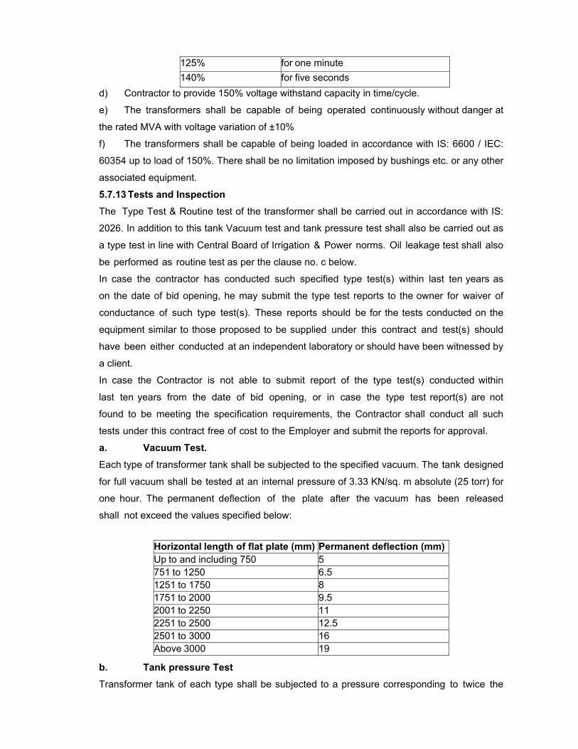
125% for one minute 140% for five seconds
d) Contractor to provide 150% voltage withstand capacity in time/cycle.
e) The transformers shall be capable of being operated continuously without danger at
the rated MVA with voltage variation of ±10%
f) The transformers shall be capable of being loaded in accordance with IS: 6600 / IEC:
60354 up to load of 150%. There shall be no limitation imposed by bushings etc. or any other
associated equipment.
5.7.13 Tests and Inspection
The Type Test & Routine test of the transformer shall be carried out in accordance with IS:
2026. In addition to this tank Vacuum test and tank pressure test shall also be carried out as
a type test in line with Central Board of Irrigation & Power norms. Oil leakage test shall also
be performed as routine test as per the clause no. c below.
In case the contractor has conducted such specified type test(s) within last ten years as
on the date of bid opening, he may submit the type test reports to the owner for waiver of
conductance of such type test(s). These reports should be for the tests conducted on the
equipment similar to those proposed to be supplied under this contract and test(s) should
have been either conducted at an independent laboratory or should have been witnessed by
a client.
In case the Contractor is not able to submit report of the type test(s) conducted within
last ten years from the date of bid opening, or in case the type test report(s) are not
found to be meeting the specification requirements, the Contractor shall conduct all such
tests under this contract free of cost to the Employer and submit the reports for approval.
a. Vacuum Test. Each type of transformer tank shall be subjected to the specified vacuum. The tank designed
for full vacuum shall be tested at an internal pressure of 3.33 KN/sq. m absolute (25 torr) for
one hour. The permanent deflection of the plate after the vacuum has been released
shall not exceed the values specified below:
b. Tank pressure Test Transformer tank of each type shall be subjected to a pressure corresponding to twice the
Horizontal length of flat plate (mm) Permanent deflection (mm) Up to and including 750 5 751 to 1250 6.5 1251 to 1750 8 1751 to 2000 9.5 2001 to 2250 11 2251 to 2500 12.5 2501 to 3000 16 Above 3000 19
normal head of oil or to the normal pressure plus 35 KN / sq. m whichever is lower,
measured at the base of the tank & maintained for one hour. The permanent deflection of
the plates after the excess pressure has been released shall not exceed the figure specified
above for vacuum test.
c. Oil leakage test on assembled transformer All tank & oil filled compartment shall be tested for oil tightness by being completely filled with
oil of viscosity not greater than that of specified oil at the ambient temperature & applying
pressure equal to the normal pressure plus 35 KN/sq. m measured at the base of the tank.
The pressure shall be maintained for a period of not less than 24 hours during which time no
sweating shall occur.
5.8 CIRCUIT BREAKERS (SF6 or VCB): Circuit Breakers shall be outdoor type, comprising three identical single pole units,
complete in all respects with all fittings and wiring.
CODES AND STANDARD
IEC- 62271-100 High-voltage switchgear and controlgear; Part 100:
alternating current circuit-breakers
5.8.1 Duty Requirements
Circuit breaker shall be totally restrike free under all duty conditions and shall be capable of
performing their duties without opening resistor. The circuit breaker shall meet the duty
requirement of any type of fault or fault location and shall be suitable for line charging and
dropping when used on 220kV effectively grounded or ungrounded systems and perform
make and break operations as per the stipulated duty cycles satisfactorily. Drawout type
outdoor breakers are not acceptable. Required gantry structures (supply & erection) for
drawal of conductor is in the scope of Contractor.
The circuit breaker shall be capable for breaking the steady & transient magnetizing current
corresponding to 220 kV transformers up to 200 MVA rating. It shall also be capable of
breaking line charging currents as per IEC- 62271-100 with a voltage factor of 1.4.
The transformer protection panel, breaker protection panel and the associated C&R panel
pertaining to 10MW PV plant shall be located within the control room of UTPP. Associated
battery bank and FCBC for this purpose shall be utilized form the existing battery and FCBC
with certain augmentation in the existing ACDB and DCDB in the UTPP. Design, fabrication,
assembly and testing and pre-shipment inspection before dispatching to site are in the scope
of the contractor.
FCBC (Float cum Boost Charger) Under normal conditions, the battery shall be on Float charger. The charger shall be
connected to a distribution board and it shall meet the requirements of DC load (coils of VCB
motors, auxillary and numerical relays, Remote annunciation Panel, indicating lamps etc.).
Capacity of the charger shall be worked out in detail depending on the DC load and the duty
cycle. Load regulation of CB C shall be 1% from full load to no-load. Charger rectifier shall be
MOSFET/IGBT/thyristor. Blocking diode in the path of battery to charger shall be provided.
Suitably rated MCBs shall be provided at input and output.
The rated transient recovery voltage for terminal fault and short line faults shall be as per
IEC:62271-100.
The circuit breakers shall be reasonably quiet in operation. Noise level in excess of 140 dB
measured at base of the breaker would be unacceptable. Contractor shall indicate the
noise level of breaker at distance of 50 to 150 m from base of the breaker.
The Contractor may note that total break time of the breaker shall not be exceeded under
any duty conditions specified such as with the combined variation of the trip coil voltage,
pneumatic pressure etc. While furnishing the proof of the total break time of complete
circuit breaker, the Contractor may specifically bring out the effect of non-simultaneity
between same pole and poles and show how it is covered in the guaranteed total break
time.
While furnishing particulars regarding the D.C. component of the circuit breaker, the
Contractor shall note that IEC-62271-100 requires that this value should correspond to the
guaranteed minimum opening time under any condition of operation.
The critical current which gives the longest arc duration at lock out pressure of
extinguishing medium and the duration shall be indicated.
All the duty requirements specified above shall be provided with the support of adequate
test reports to be furnished along with the bid.
5.8.2 Constructional Features
All making and breaking contacts shall be sealed and free from atmospheric effect. In the
event of leakage of extinguishing medium to a value, which cannot withstand the dielectric
stresses specified in the open position, the contacts shall preferably self close. Main
contacts shall be first to close and the last to open and shall be easily accessible for
inspection and replacement. If there are no separately mounted arcing contacts, then the
main contacts shall be easily accessible for inspection and replacement. Main contacts shall
have ample area and contact pressure for carrying the rated current under all conditions.
The interrupter sectional drawing showing the following conditions shall be furnished for
information with the bid:
a) Close position
b) Arc initiation position
c) Full arcing position
d) Arc extinction position
e) Open position.
All the three poles of the breaker shall be linked together.
Circuit breakers shall be provided with two (2) independent trip coils, suitable for trip circuit
supervision. The trip circuit supervision relay would also be provided. Necessary terminals
shall be provided in the central control cabinet of the circuit breaker.
5.8.3 Sulphur Hexaflouride (SF6) Gas Circuit Breaker Circuit breakers shall be single pressure type.
Design and construction of the circuit breaker shall be such that there is minimum possibility
of gas leakage and entry of moisture. There should not be any condensation of SF6 gas on
insulated surfaces of the circuit breaker.
In the interrupter assembly, there shall be absorbing product box to eliminate SF6
decomposition products and moisture. The details and operating experience with such filters
shall be brought out in additional information schedule.
Each pole shall form an enclosure filled with SF6 gas independent of two other poles.
Common monitoring of SF6 gas can be provided for the three poles of circuit breaker
having a common drive. The interconnecting pipes in this case shall be such that the SF6
gas from one pole could be removed for maintenance purposes.
Material used in the construction of circuit breakers shall be such as fully compatible with
SF6.
The SF6 gas density monitor shall be adequately temperature compensated to model the
density changes due to variations in ambient temperature within the body of circuit breaker
as a whole. It shall be possible to dismantle the monitor without removal of gas.
Sufficient SF6 gas shall be supplied to fill all the circuit breakers installed plus an
additional 20% of the quantity as spare.
5.8.4 Operating Mechanism
Circuit breaker shall be operated by electrically spring charged mechanism only.
The operating mechanism shall be anti-pumping and trip free (as per IEC definition)
electrically and either mechanically or pneumatically under every method of closing. The
mechanism of the breaker shall be such that the position of the breaker is maintained even
after the leakage of operating media and/or gas.
The operating mechanism shall be such that the failure of any auxiliary spring will not
prevent tripping and will not cause trip or closing operation of the power operated closing
devices. A mechanical indicator shall be provided to show open and close positions of
breaker. It shall be located in a position where it will be visible to a man standing on the
ground with the mechanism housing door closed. An operation counter shall also be
provided.
Closing coil shall operate correctly at all values of voltage between 85% and 110% of the
rated voltage. Shunt trip coils shall operate correctly under all operating conditions of the
circuit breaker upto the rated breaking capacity of the circuit breaker and at all values of
supply voltage between 70% and 110% of rated voltage. If additional elements are
introduced in the trip coil circuit their successful operation for similar applications of
outdoor breaker shall be clearly brought out in the bid.
Working parts of the mechanism shall be of corrosion resisting material. Bearings requiring
grease shall be equipped with pressure type grease fittings. Bearing pin, bolts, nuts and
other parts shall be adequately pinned or locked to prevent loosening or changing
adjustment with repeated operation of the breaker.
Operating mechanism shall normally be operated by remote electrical control. Electrical
tripping shall be performed by shunt trip coil. Provision shall also be made for local
electrical control. ‘Local / remote’ selector switch and close & trip push buttons shall be
provided in the breaker central control cabinet. Remote located push buttons and indicating
lamps shall also be provided.
Operating mechanism and all accessories shall be in local control cabinet. A central
control cabinet for the three poles of the breaker shall be provided along with supply of
necessary tubing, cables, etc.
Provisions shall be made on breakers for attaching an operation analyser to perform
speed tests after installation at site to record contact travel against time and measure
opening time.
The Contractor shall furnish curve supported by test data indicating the opening time
under close-open operation with combined variation of trip coil and operating media along
with the bid.
5.8.5 Spring Operated Mechanism
Spring operated mechanism shall be complete with motor, opening spring & closing
spring with limit switch for automatic charging and other necessary accessories to make
the mechanism a complete operating unit. Opening spring shall be supplied with limit
switch for automatic charging and other necessary accessories.
As long as power is available to the motor, a continuous sequence of closing and
opening operations shall be possible. The motor shall have adequate thermal rating for this
duty. After failure of power supply to the motor, one close- open operation shall be possible
with the energy contained in the operating mechanism.
Breaker operation shall be independent of the motor, which shall be used solely for
compressing the closing spring.
Motor shall comply with the requirements specified in Clause No. 5.16. Motor ratings shall
be such that it requires not more than 30 seconds for fully charging the closing spring.
Closing action of the circuit breaker shall compress the opening spring ready for tripping.
When closing springs are discharged, after closing a breaker, closing springs shall
automatically be charged for the next operation and an indication of this shall be provided
in the local and remote control cabinet.
The spring operating mechanism shall have adequate energy stored in the operating
spring to close and latch the circuit breaker against the rated making current and also to
provide the required energy for the tripping mechanism in case the tripping energy is
derived from the operating mechanism.
5.8.6 Fittings and Accessories
Following is partial list of some of the major fittings and accessories to be furnished as
integral part of the breakers. Number and exact location of these parts shall be indicated in
the bid.
Control unit / Central control cabinet in accordance with Clause No. 5.16 complete
with:
1. Double compression type cable glands, lugs, ferrules, etc.
2. Local/remote changeover switch
3. Operation counter located in control unit or central control unit.
4. Fuses, as required
5. Antipumping relay/contactor
6. Rating and diagram plate in accordance with IEC including year of manufacture,
etc.
7. Gauges for SF6 gas pressure, pneumatic/hydraulic pressure.
8. Gas density monitor with alarm and lockout contacts
5.8.7 Hollow insulator columns
The insulators shall conform to requirements stipulated in Clause No. 5.16. All routine tests
shall be conducted on the insulators as per relevant IEC. In addition the following routine
tests shall also be conducted on hollow column insulators :
a) Ultrasonic test
b) Pressure test
c) Bending load test in 4 directions at 50% specified bending load.
d) Bending load test in 4 directions at 100% specified Bending load as a sample test.
e) Burst pressure test as a sample test.
5.8.8 Support Structures
The minimum height of equipment supports shall be 2.55 meters. The height of center line
of conductor shall be as given elsewhere in the specification.
Terminal connectors shall conform to requirements stipulated in Clause No. 5.16.
5.8.9 Routine Tests
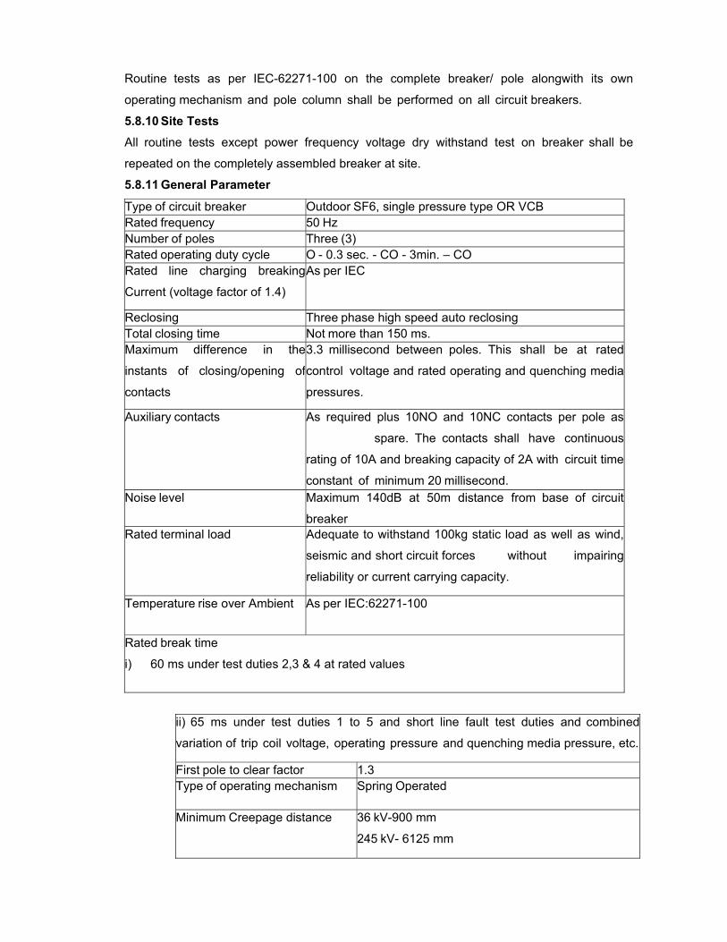
Routine tests as per IEC-62271-100 on the complete breaker/ pole alongwith its own
operating mechanism and pole column shall be performed on all circuit breakers.
5.8.10 Site Tests
All routine tests except power frequency voltage dry withstand test on breaker shall be
repeated on the completely assembled breaker at site.
5.8.11 General Parameter
Type of circuit breaker Outdoor SF6, single pressure type OR VCB Rated frequency 50 Hz Number of poles Three (3) Rated operating duty cycle O - 0.3 sec. - CO - 3min. – CO Rated line charging breaking
Current (voltage factor of 1.4)
As per IEC
Reclosing Three phase high speed auto reclosing Total closing time Not more than 150 ms. Maximum difference in the
instants of closing/opening of
contacts
3.3 millisecond between poles. This shall be at rated
control voltage and rated operating and quenching media
pressures.
Auxiliary contacts As required plus 10NO and 10NC contacts per pole as
spare. The contacts shall have continuous
rating of 10A and breaking capacity of 2A with circuit time
constant of minimum 20 millisecond. Noise level Maximum 140dB at 50m distance from base of circuit
breaker Rated terminal load Adequate to withstand 100kg static load as well as wind,
seismic and short circuit forces without impairing
reliability or current carrying capacity.
Temperature rise over Ambient As per IEC:62271-100
Rated break time
i) 60 ms under test duties 2,3 & 4 at rated values
ii) 65 ms under test duties 1 to 5 and short line fault test duties and combined
variation of trip coil voltage, operating pressure and quenching media pressure, etc.
First pole to clear factor 1.3 Type of operating mechanism Spring Operated
Minimum Creepage distance 36 kV-900 mm
245 kV- 6125 mm
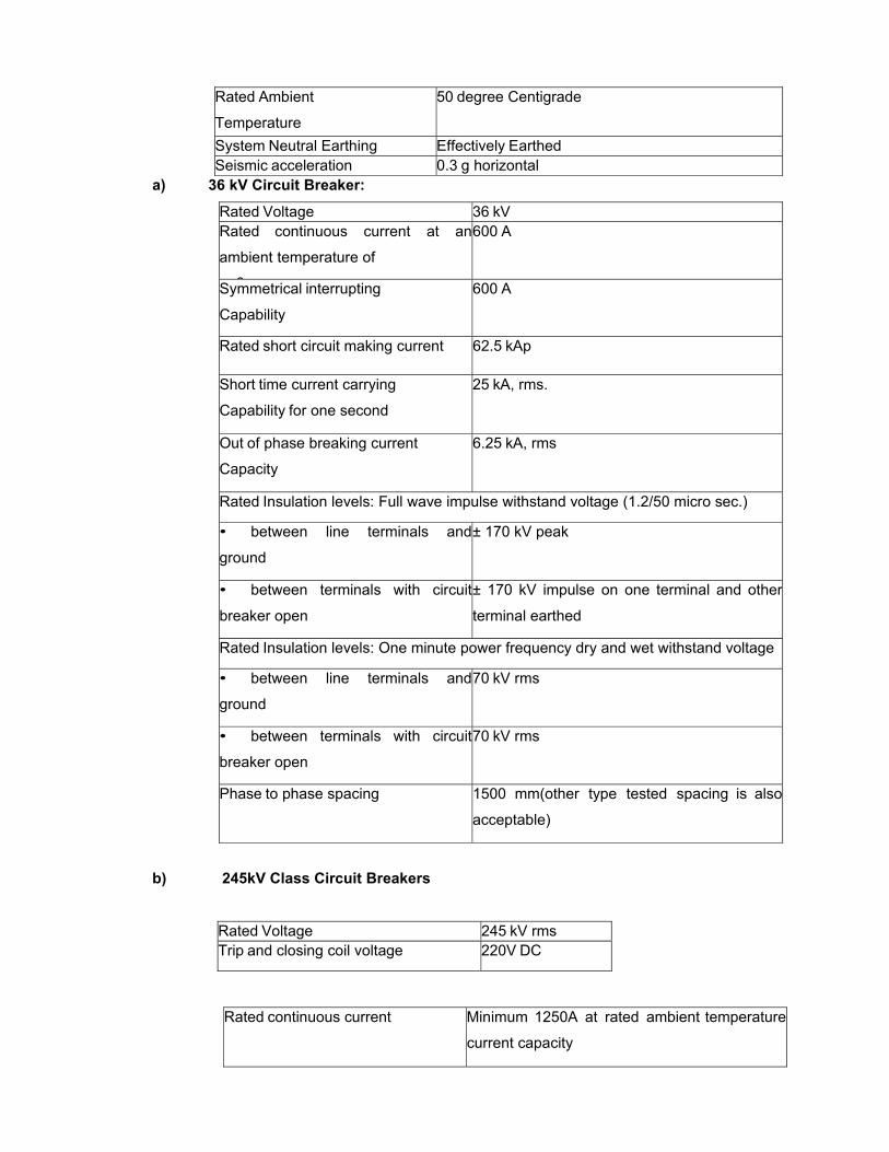
Rated Ambient
Temperature
50 degree Centigrade
System Neutral Earthing Effectively Earthed Seismic acceleration 0.3 g horizontal
a) 36 kV Circuit Breaker:
Rated Voltage 36 kV Rated continuous current at an
ambient temperature of
0
600 A
Symmetrical interrupting
Capability
600 A
Rated short circuit making current 62.5 kAp
Short time current carrying
Capability for one second
25 kA, rms.
Out of phase breaking current
Capacity
6.25 kA, rms
Rated Insulation levels: Full wave impulse withstand voltage (1.2/50 micro sec.)
• between line terminals and
ground
± 170 kV peak
• between terminals with circuit
breaker open
± 170 kV impulse on one terminal and other
terminal earthed
Rated Insulation levels: One minute power frequency dry and wet withstand voltage
• between line terminals and
ground
70 kV rms
• between terminals with circuit
breaker open
70 kV rms
Phase to phase spacing 1500 mm(other type tested spacing is also
acceptable)
b) 245kV Class Circuit Breakers
Rated Voltage 245 kV rms Trip and closing coil voltage 220V DC
Rated continuous current Minimum 1250A at rated ambient temperature
current capacity
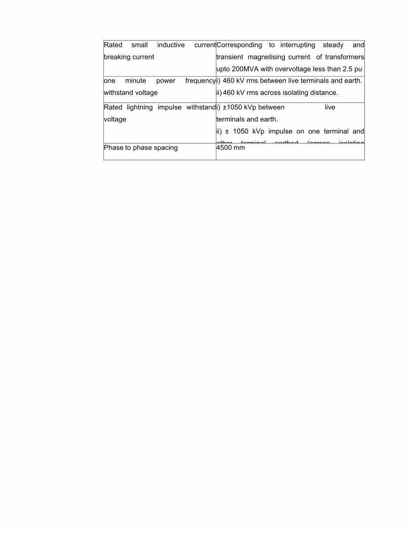
Rated small inductive current
breaking current
Corresponding to interrupting steady and
transient magnetising current of transformers
upto 200MVA with overvoltage less than 2.5 pu
one minute power frequency
withstand voltage
i) 460 kV rms between live terminals and earth.
ii) 460 kV rms across isolating distance.
Rated lightning impulse withstand
voltage
i) ±1050 kVp between live
terminals and earth.
ii) ± 1050 kVp impulse on one terminal and
other terminal earthed (across isolatingPhase to phase spacing 4500 mm

5.9 ISOLATORS: The isolators and accessories shall conform in general to IEC 62271-102 (or equivalent
Indian standard) except to the extent explicitly modified in specification.
Earth switches shall be provided on isolators wherever called for.
The isolators and earth switches for 245kV only shall be motor operated. The isolators
and earth switches shall be hand operated for 36kV.
Complete isolator with all the necessary items for successful operation shall be supplied.
Isolators shall be horizontal centre break type and Tandem type as per single line
diagram
DUTY REQUIREMENTS
Isolators and earth switches shall be capable of withstanding the dynamic and thermal
effects of the maximum possible short circuit current of the system in their closed
position. They shall be constructed such that they do not open under influence of
short circuit current and wind pressure together. The earth switches wherever provided
shall be constructional interlocked so that the earth switches can be operated only when
the isolator is open and vice-versa.
In addition to the constructional interlock, isolator and earth switches shall have provision
to prevent their electrical and manual operation unless the associated and other
interlocking conditions are met. All these interlocks shall be of fail safe type. Suitable
individual interlocking coil arrangements shall be provided. The interlocking coil shall be
suitable for continuous operation from DC supply and within a variation range as
stipulated in relevant section. The interlock coil shall be provided with adequate
contacts for facilitating permissive logic for ‘DC’ control scheme of the isolator as well
as for AC circuit of the motor to prevent opening or closing of isolators when the
interlocking coil is not energized.
The earthing switches shall be capable of discharging trapped charges of the
associated lines.
Isolator and earth switches shall be able to bear on the terminals the total forces including
wind loading and electrodynamic forces on the attached conductor without impairing
reliability or current carrying capacity.
The isolator shall be capable for making / breaking normal currents when no significant
change in voltage occurs across the terminals of each pole of the isolator on account of
making / breaking operation.
CONSTRUCTIONAL FEATURES
The isolators shall be provided with high pressure current carrying contacts on the
hinge/ jaw ends and all contact surfaces shall be silver plated. The thickness of silver
plating should not be less than 25 microns. The contacts shall be accurately
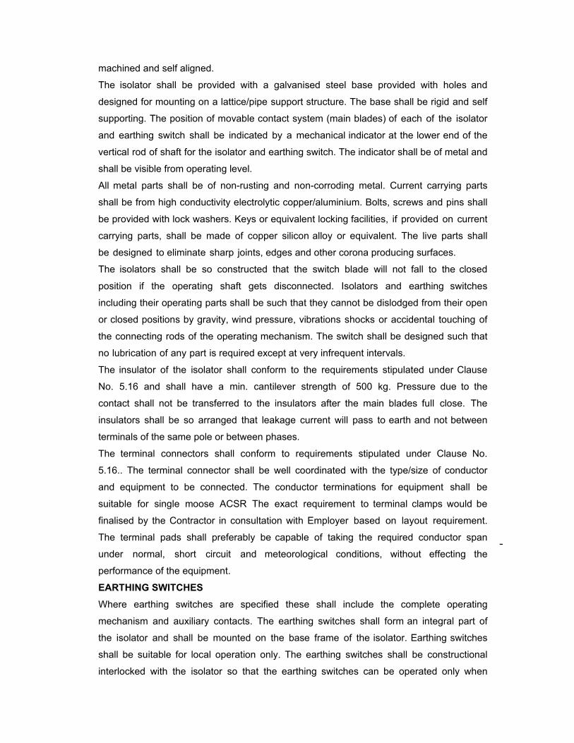
machined and self aligned.
The isolator shall be provided with a galvanised steel base provided with holes and
designed for mounting on a lattice/pipe support structure. The base shall be rigid and self
supporting. The position of movable contact system (main blades) of each of the isolator
and earthing switch shall be indicated by a mechanical indicator at the lower end of the
vertical rod of shaft for the isolator and earthing switch. The indicator shall be of metal and
shall be visible from operating level.
All metal parts shall be of non-rusting and non-corroding metal. Current carrying parts
shall be from high conductivity electrolytic copper/aluminium. Bolts, screws and pins shall
be provided with lock washers. Keys or equivalent locking facilities, if provided on current
carrying parts, shall be made of copper silicon alloy or equivalent. The live parts shall
be designed to eliminate sharp joints, edges and other corona producing surfaces.
The isolators shall be so constructed that the switch blade will not fall to the closed
position if the operating shaft gets disconnected. Isolators and earthing switches
including their operating parts shall be such that they cannot be dislodged from their open
or closed positions by gravity, wind pressure, vibrations shocks or accidental touching of
the connecting rods of the operating mechanism. The switch shall be designed such that
no lubrication of any part is required except at very infrequent intervals.
The insulator of the isolator shall conform to the requirements stipulated under Clause
No. 5.16 and shall have a min. cantilever strength of 500 kg. Pressure due to the
contact shall not be transferred to the insulators after the main blades full close. The
insulators shall be so arranged that leakage current will pass to earth and not between
terminals of the same pole or between phases.
The terminal connectors shall conform to requirements stipulated under Clause No.
5.16.. The terminal connector shall be well coordinated with the type/size of conductor
and equipment to be connected. The conductor terminations for equipment shall be
suitable for single moose ACSR The exact requirement to terminal clamps would be
finalised by the Contractor in consultation with Employer based on layout requirement.
The terminal pads shall preferably be capable of taking the required conductor span
under normal, short circuit and meteorological conditions, without effecting the
performance of the equipment.
EARTHING SWITCHES
Where earthing switches are specified these shall include the complete operating
mechanism and auxiliary contacts. The earthing switches shall form an integral part of
the isolator and shall be mounted on the base frame of the isolator. Earthing switches
shall be suitable for local operation only. The earthing switches shall be constructional
interlocked with the isolator so that the earthing switches can be operated only when
isolator is open and vice versa.
OPERATING MECHANISM AND CONTROL
The Contractor shall offer, motor operated switches for 245kV and hand operated for 36kV
having padlock arrangement on both ‘ON’ and ‘OFF’ positions.
Limit switches for control shall be fitted on the isolator/ earth switch shaft, within the
cabinet to sense the open and close positions of the isolators and earth switches.
It shall not be possible, after final adjustment has been made for any part of the
mechanism to be displaced at any point in the travel sufficient enough to allow improper
functioning of the isolator when the isolator is opened or closed at any speed.
Control cabinet/operating mech. box shall conform to requirements stipulated in Clause
No. 5.16 and IS: 5039/IS 8623/IEC 439 as applicable.
OPERATION
Isolator shall be gang operated for main blades and earth switches. The operation of the
three poles shall be well synchronized and interlocked.
The design shall be such as to provide maximum reliability under all service
conditions. All operating linkages carrying mechanical loads shall be designed for
negligible deflection. The length of inter insulator and interpole operating rods shall be
capable of adjustments.
The design of linkages and gears shall be such so as to allow one man to operate
the handle with ease for isolator and earth switch.
TESTS
In continuation to the requirements stipulated under Clause No. 5.11, the isolator
alongwith operating mechanism shall conform to the type tests and shall be subjected to
routine tests and acceptance tests in accordance with IEC
62271-102. Minimum 50 nos. mechanical operations will be carried out on 1 (one)
isolator assembled completely with all accessories as acceptance test. During final
testing of isolator sequential closing/ opening of earth switch shall also be checked only
after isolator is fully open/close. Acceptance test shall be carried out with operating box.
The insulator shall conform to all the type tests as per IEC 60168. All routine and
acceptance tests as per IEC-60168 shall also be carried out.
PARAMETERS
GENERAL
Type of isolator Outdoor type Rated frequency 50 Hz Number of poles Three (3) Operating time Not more than 12 sec
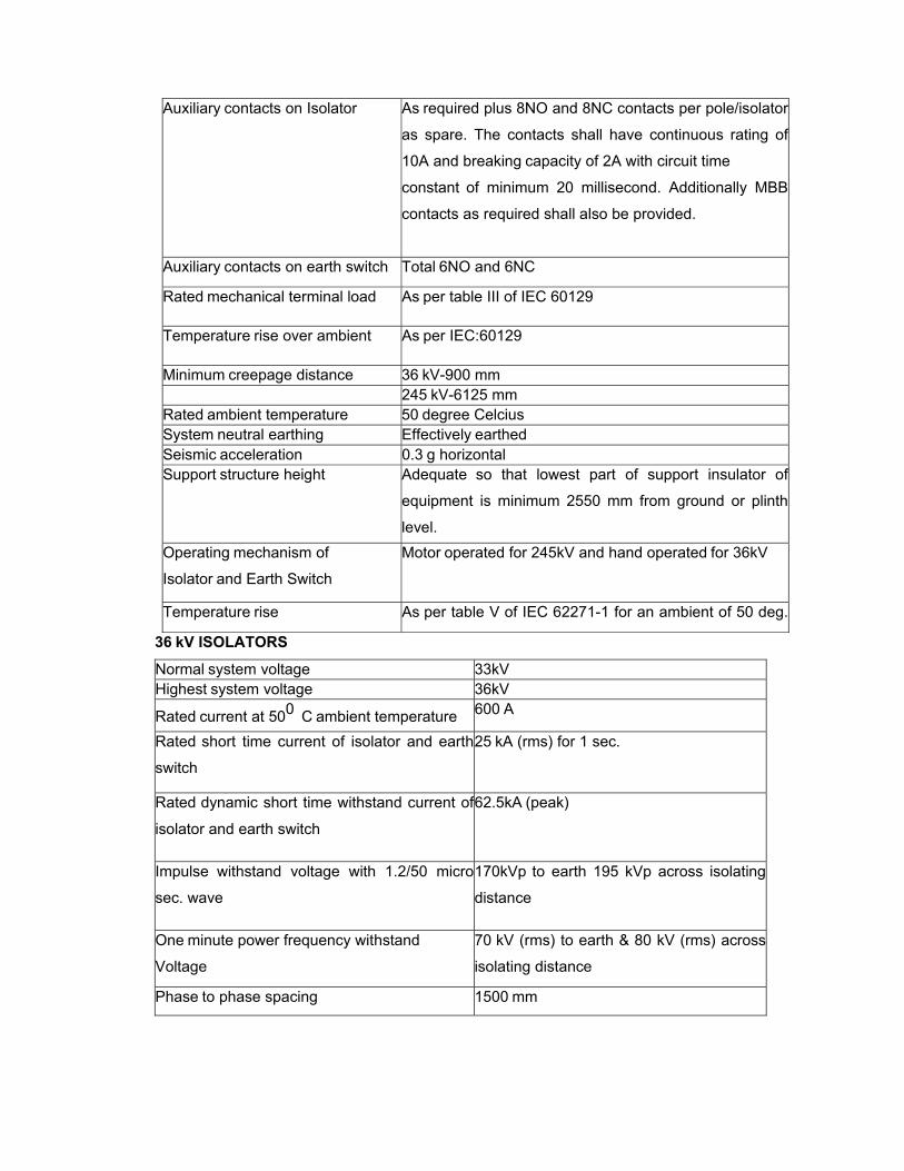
Auxiliary contacts on Isolator As required plus 8NO and 8NC contacts per pole/isolator
as spare. The contacts shall have continuous rating of
10A and breaking capacity of 2A with circuit time
constant of minimum 20 millisecond. Additionally MBB
contacts as required shall also be provided.
Auxiliary contacts on earth switch Total 6NO and 6NC
Rated mechanical terminal load As per table III of IEC 60129
Temperature rise over ambient As per IEC:60129
Minimum creepage distance 36 kV-900 mm 245 kV-6125 mm Rated ambient temperature 50 degree Celcius System neutral earthing Effectively earthed Seismic acceleration 0.3 g horizontal Support structure height Adequate so that lowest part of support insulator of
equipment is minimum 2550 mm from ground or plinth
level. Operating mechanism of
Isolator and Earth Switch
Motor operated for 245kV and hand operated for 36kV
Temperature rise As per table V of IEC 62271-1 for an ambient of 50 deg.
36 kV ISOLATORS
Normal system voltage 33kV Highest system voltage 36kV
Rated current at 500 C ambient temperature 600 A
Rated short time current of isolator and earth
switch
25 kA (rms) for 1 sec.
Rated dynamic short time withstand current of
isolator and earth switch
62.5kA (peak)
Impulse withstand voltage with 1.2/50 micro
sec. wave
170kVp to earth 195 kVp across isolating
distance
One minute power frequency withstand
Voltage
70 kV (rms) to earth & 80 kV (rms) across
isolating distance
Phase to phase spacing 1500 mm
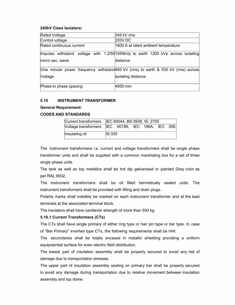
245kV Class Isolators:
Rated Voltage 245 kV rms Control voltage 220V DC Rated continuous current 1600 A at rated ambient temperature
Impulse withstand voltage with 1.2/50
micro sec. wave
1050kVp to earth 1200 kVp across isolating
distance
One minute power frequency withstand
Voltage
460 kV (rms) to earth & 530 kV (rms) across
isolating distance
Phase to phase spacing 4500 mm
5.10 INSTRUMENT TRANSFORMER General Requirement: CODES AND STANDARDS
Current transformers IEC 60044, BS:3938, IS: 2705 Voltage transformers IEC 60186, IEC 186A, IEC 358,
Insulating oil IS:335
The instrument transformers i.e. current and voltage transformers shall be single phase
transformer units and shall be supplied with a common marshaling box for a set of three
single phase units.
The tank as well as top metallics shall be hot dip galvanised or painted Grey color as
per RAL 9002.
The instrument transformers shall be oil filled hermetically sealed units. The
instrument transformers shall be provided with filling and drain plugs.
Polarity marks shall indelibly be marked on each instrument transformer and at the lead
terminals at the associated terminal block.
The insulators shall have cantilever strength of more than 500 kg.
5.10.1 Current Transformers (CTs) The CTs shall have single primary of either ring type or hair pin type or bar type. In case
of "Bar Primary" inverted type CTs, the following requirements shall be met:
The secondaries shall be totally encased in metallic shielding providing a uniform
equipotential surface for even electric field distribution.
The lowest part of insulation assembly shall be properly secured to avoid any risk of
damage due to transportation stresses.
The upper part of insulation assembly sealing on primary bar shall be properly secured
to avoid any damage during transportation due to relative movement between insulation
assembly and top dome.
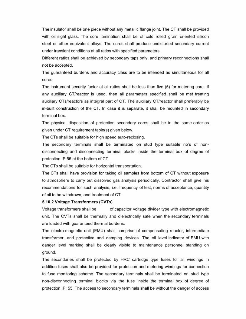
The insulator shall be one piece without any metallic flange joint. The CT shall be provided
with oil sight glass. The core lamination shall be of cold rolled grain oriented silicon
steel or other equivalent alloys. The cores shall produce undistorted secondary current
under transient conditions at all ratios with specified parameters.
Different ratios shall be achieved by secondary taps only, and primary reconnections shall
not be accepted.
The guaranteed burdens and accuracy class are to be intended as simultaneous for all
cores.
The instrument security factor at all ratios shall be less than five (5) for metering core. If
any auxiliary CT/reactor is used, then all parameters specified shall be met treating
auxiliary CTs/reactors as integral part of CT. The auxiliary CT/reactor shall preferably be
in-built construction of the CT. In case it is separate, it shall be mounted in secondary
terminal box.
The physical disposition of protection secondary cores shall be in the same order as
given under CT requirement table(s) given below.
The CTs shall be suitable for high speed auto-reclosing.
The secondary terminals shall be terminated on stud type suitable no’s of non-
disconnecting and disconnecting terminal blocks inside the terminal box of degree of
protection IP:55 at the bottom of CT.
The CTs shall be suitable for horizontal transportation.
The CTs shall have provision for taking oil samples from bottom of CT without exposure
to atmosphere to carry out dissolved gas analysis periodically. Contractor shall give his
recommendations for such analysis, i.e. frequency of test, norms of acceptance, quantity
of oil to be withdrawn, and treatment of CT.
5.10.2 Voltage Transformers (CVTs) Voltage transformers shall be of capacitor voltage divider type with electromagnetic
unit. The CVTs shall be thermally and dielectrically safe when the secondary terminals
are loaded with guaranteed thermal burdens.
The electro-magnetic unit (EMU) shall comprise of compensating reactor, intermediate
transformer, and protective and damping devices. The oil level indicator of EMU with
danger level marking shall be clearly visible to maintenance personnel standing on
ground.
The secondaries shall be protected by HRC cartridge type fuses for all windings In
addition fuses shall also be provided for protection and metering windings for connection
to fuse monitoring scheme. The secondary terminals shall be terminated on stud type
non-disconnecting terminal blocks via the fuse inside the terminal box of degree of
protection IP: 55. The access to secondary terminals shall be without the danger of access
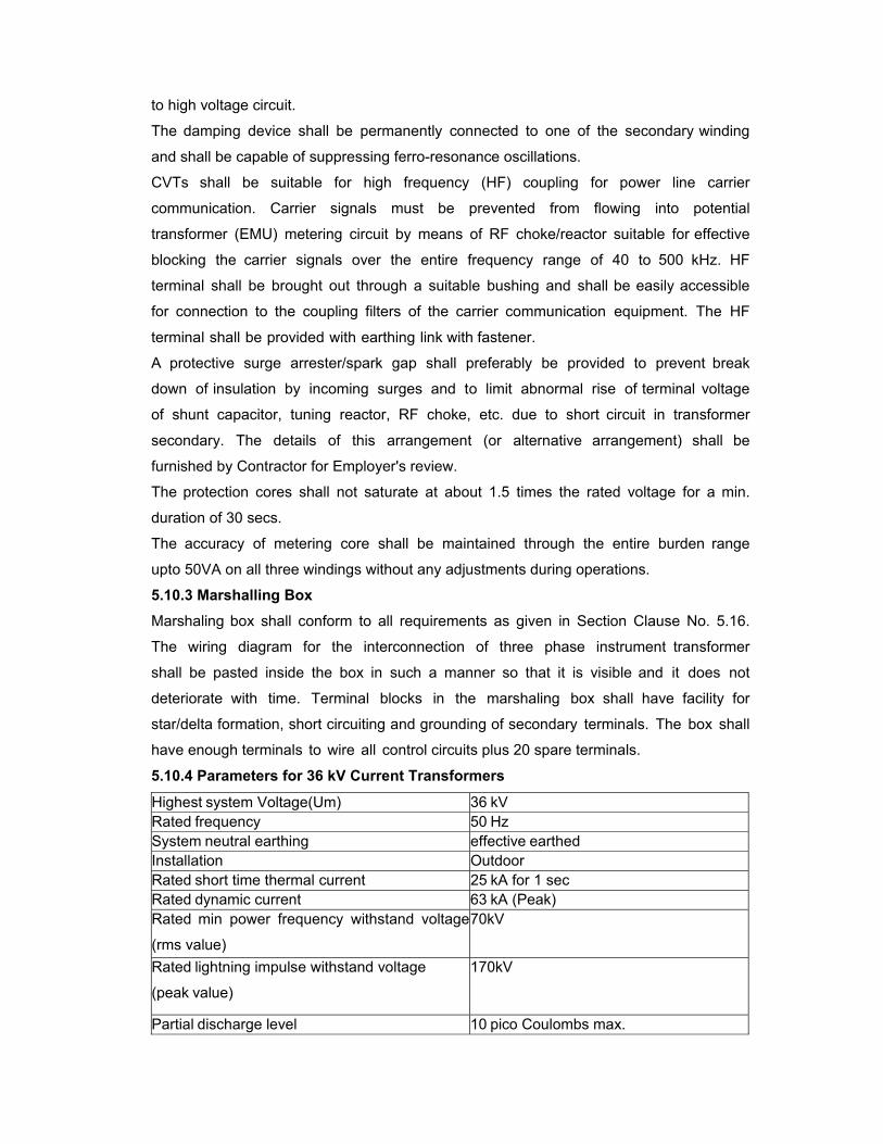
to high voltage circuit.
The damping device shall be permanently connected to one of the secondary winding
and shall be capable of suppressing ferro-resonance oscillations.
CVTs shall be suitable for high frequency (HF) coupling for power line carrier
communication. Carrier signals must be prevented from flowing into potential
transformer (EMU) metering circuit by means of RF choke/reactor suitable for effective
blocking the carrier signals over the entire frequency range of 40 to 500 kHz. HF
terminal shall be brought out through a suitable bushing and shall be easily accessible
for connection to the coupling filters of the carrier communication equipment. The HF
terminal shall be provided with earthing link with fastener.
A protective surge arrester/spark gap shall preferably be provided to prevent break
down of insulation by incoming surges and to limit abnormal rise of terminal voltage
of shunt capacitor, tuning reactor, RF choke, etc. due to short circuit in transformer
secondary. The details of this arrangement (or alternative arrangement) shall be
furnished by Contractor for Employer's review.
The protection cores shall not saturate at about 1.5 times the rated voltage for a min.
duration of 30 secs.
The accuracy of metering core shall be maintained through the entire burden range
upto 50VA on all three windings without any adjustments during operations.
5.10.3 Marshalling Box
Marshaling box shall conform to all requirements as given in Section Clause No. 5.16.
The wiring diagram for the interconnection of three phase instrument transformer
shall be pasted inside the box in such a manner so that it is visible and it does not
deteriorate with time. Terminal blocks in the marshaling box shall have facility for
star/delta formation, short circuiting and grounding of secondary terminals. The box shall
have enough terminals to wire all control circuits plus 20 spare terminals.
5.10.4 Parameters for 36 kV Current Transformers
Highest system Voltage(Um) 36 kV Rated frequency 50 Hz System neutral earthing effective earthed Installation Outdoor Rated short time thermal current 25 kA for 1 sec Rated dynamic current 63 kA (Peak) Rated min power frequency withstand voltage
(rms value)
70kV
Rated lightning impulse withstand voltage
(peak value)
170kV
Partial discharge level 10 pico Coulombs max.
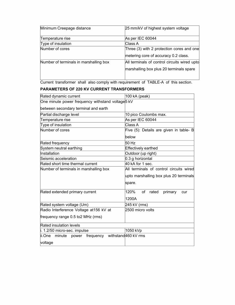
Minimum Creepage distance 25 mm/kV of highest system voltage
Temperature rise As per IEC 60044 Type of insulation Class A Number of cores Three (3) with 2 protection cores and one
metering core of accuracy 0.2 class. Number of terminals in marshalling box All terminals of control circuits wired upto
marshalling box plus 20 terminals spare
Current transformer shall also comply with requirement of TABLE-A of this section.
PARAMETERS OF 220 KV CURRENT TRANSFORMERS
Rated dynamic current 100 kA (peak) One minute power frequency withstand voltage
between secondary terminal and earth
5 kV
Partial discharge level 10 pico Coulombs max. Temperature rise As per IEC 60044 Type of insulation Class A Number of cores Five (5): Details are given in table- B
below Rated frequency 50 Hz System neutral earthing Effectively earthed Installation Outdoor (up right) Seismic acceleration 0.3 g horizontal Rated short time thermal current 40 kA for 1 sec. Number of terminals in marshalling box All terminals of control circuits wired
upto marshalling box plus 20 terminals
spare.
Rated extended primary current 120% of rated primary cur
1200A Rated system voltage (Um) 245 kV (rms) Radio Interference Voltage at156 kV at
frequency range 0.5 to2 MHz (rms)
2500 micro volts
Rated insulation levels i. 1.2/50 micro-sec. impulse 1050 kVp ii.One minute power frequency withstand
voltage
460 kV rms
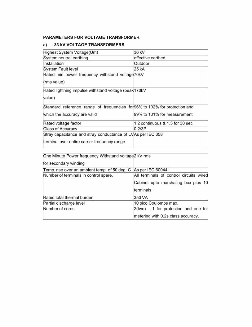
PARAMETERS FOR VOLTAGE TRANSFORMER
a) 33 kV VOLTAGE TRANSFORMERS
Highest System Voltage(Um) 36 kV System neutral earthing effective earthed Installation Outdoor System Fault level 25 kA Rated min power frequency withstand voltage
(rms value)
70kV
Rated lightning impulse withstand voltage (peak
value)
170kV
Standard reference range of frequencies for
which the accuracy are valid
96% to 102% for protection and
99% to 101% for measurement
Rated voltage factor 1.2 continuous & 1.5 for 30 sec Class of Accuracy 0.2/3P Stray capacitance and stray conductance of LV
terminal over entire carrier frequency range
As per IEC:358
One Minute Power frequency Withstand voltage
for secondary winding
2 kV rms
Temp. rise over an ambient temp. of 50 deg. C As per IEC 60044 Number of terminals in control spare. All terminals of control circuits wired
Cabinet upto marshaling box plus 10
terminals
Rated total thermal burden 350 VA Partial discharge level 10 pico Coulombs max. Number of cores 2(two) – 1 for protection and one for
metering with 0.2s class accuracy.
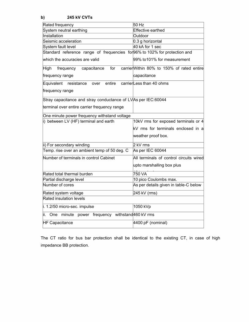
b) 245 kV CVTs
Rated frequency 50 Hz System neutral earthing Effective earthed Installation Outdoor Seismic acceleration 0.3 g horizontal System fault level 40 kA for 1 sec Standard reference range of frequencies for
which the accuracies are valid
96% to 102% for protection and
99% to101% for measurement
High frequency capacitance for carrier
frequency range
Within 80% to 150% of rated entire
capacitance
Equivalent resistance over entire carrier
frequency range
Less than 40 ohms
Stray capacitance and stray conductance of LV
terminal over entire carrier frequency range
As per IEC:60044
One minute power frequency withstand voltage i) between LV (HF) terminal and earth 10kV rms for exposed terminals or 4
kV rms for terminals enclosed in a
weather proof box.
ii) For secondary winding 2 kV rms Temp. rise over an ambient temp of 50 deg. C As per IEC 60044
Number of terminals in control Cabinet All terminals of control circuits wired
upto marshalling box plus
10 t i lRated total thermal burden 750 VA Partial discharge level 10 pico Coulombs max. Number of cores As per details given in table-C below
Rated system voltage 245 kV (rms) Rated insulation levels
i. 1.2/50 micro-sec. impulse 1050 kVp
ii. One minute power frequency withstand460 kV rms
HF Capacitance 4400 pF (nominal)
The CT ratio for bus bar protection shall be identical to the existing CT, in case of high
impedance BB protection.
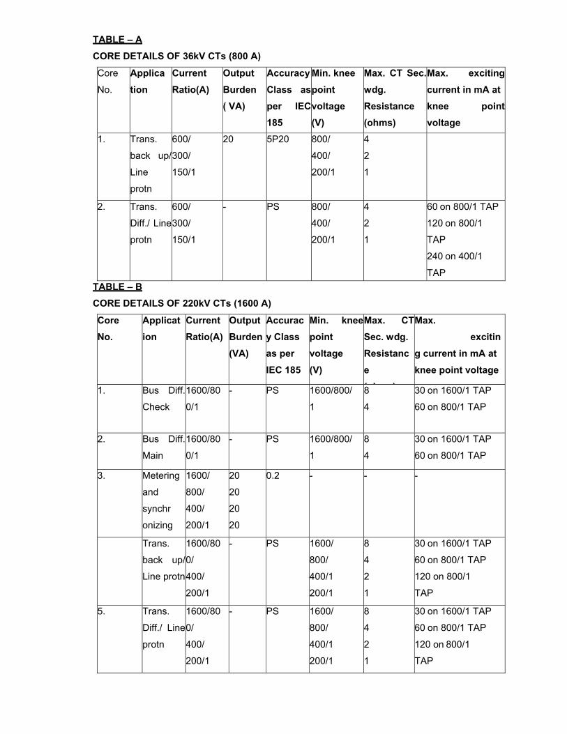
TABLE – A
CORE DETAILS OF 36kV CTs (800 A)
Core
No.
Applica tion
Current Ratio(A)
Output Burden ( VA)
AccuracyClass asper IEC 185
Min. knee
point voltage (V)
Max. CT Sec.wdg. Resistance (ohms)
Max. exciting current in mA atknee point voltage
1. Trans.
back up/
Line
protn
600/
300/
150/1
20 5P20 800/
400/
200/1
4
2
1
2. Trans.
Diff./ Line
protn
600/
300/
150/1
- PS 800/
400/
200/1
4
2
1
60 on 800/1 TAP
120 on 800/1
TAP
240 on 400/1
TAP TABLE – B
CORE DETAILS OF 220kV CTs (1600 A)
Core
No. Applicat ion
Current Ratio(A)
Output Burden(VA)
Accuracy Class
as per IEC 185
Min. knee point voltage
(V)
Max. CT Sec. wdg. Resistance
( h )
Max. exciting current in mA at knee point voltage
1. Bus Diff.
Check
1600/80
0/1
- PS 1600/800/
1
8
4
30 on 1600/1 TAP
60 on 800/1 TAP
2. Bus Diff.
Main
1600/80
0/1
- PS 1600/800/
1
8
4
30 on 1600/1 TAP
60 on 800/1 TAP
3. Metering
and
synchr
onizing
1600/
800/
400/
200/1
20
20
20
20
0.2 - - -
Trans.
back up/
Line protn
1600/80
0/
400/
200/1
- PS 1600/
800/
400/1
200/1
8
4
2
1
30 on 1600/1 TAP
60 on 800/1 TAP
120 on 800/1
TAP
5. Trans.
Diff./ Line
protn
1600/80
0/
400/
200/1
- PS 1600/
800/
400/1
200/1
8
4
2
1
30 on 1600/1 TAP
60 on 800/1 TAP
120 on 800/1
TAP
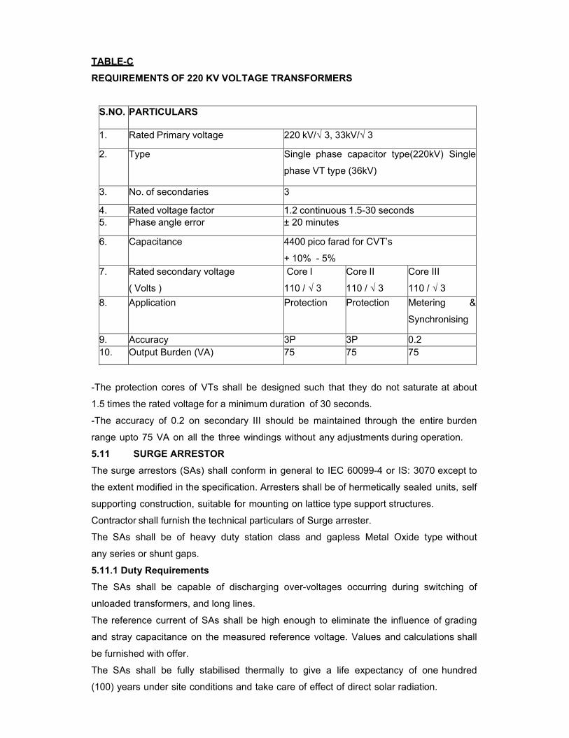
TABLE-C
REQUIREMENTS OF 220 KV VOLTAGE TRANSFORMERS
S.NO. PARTICULARS
1. Rated Primary voltage 220 kV/√ 3, 33kV/√ 3
2. Type
Single phase capacitor type(220kV) Single
phase VT type (36kV)
3. No. of secondaries 3
4. Rated voltage factor 1.2 continuous 1.5-30 seconds 5. Phase angle error ± 20 minutes
6. Capacitance 4400 pico farad for CVT’s
+ 10% - 5% 7. Rated secondary voltage
( Volts )
Core I
110 / √ 3
Core II
110 / √ 3
Core III
110 / √ 3 8. Application Protection Protection Metering &
Synchronising
9. Accuracy 3P 3P 0.2 10. Output Burden (VA) 75 75 75
-The protection cores of VTs shall be designed such that they do not saturate at about
1.5 times the rated voltage for a minimum duration of 30 seconds.
-The accuracy of 0.2 on secondary III should be maintained through the entire burden
range upto 75 VA on all the three windings without any adjustments during operation.
5.11 SURGE ARRESTOR
The surge arrestors (SAs) shall conform in general to IEC 60099-4 or IS: 3070 except to
the extent modified in the specification. Arresters shall be of hermetically sealed units, self
supporting construction, suitable for mounting on lattice type support structures.
Contractor shall furnish the technical particulars of Surge arrester.
The SAs shall be of heavy duty station class and gapless Metal Oxide type without
any series or shunt gaps.
5.11.1 Duty Requirements
The SAs shall be capable of discharging over-voltages occurring during switching of
unloaded transformers, and long lines.
The reference current of SAs shall be high enough to eliminate the influence of grading
and stray capacitance on the measured reference voltage. Values and calculations shall
be furnished with offer.
The SAs shall be fully stabilised thermally to give a life expectancy of one hundred
(100) years under site conditions and take care of effect of direct solar radiation.
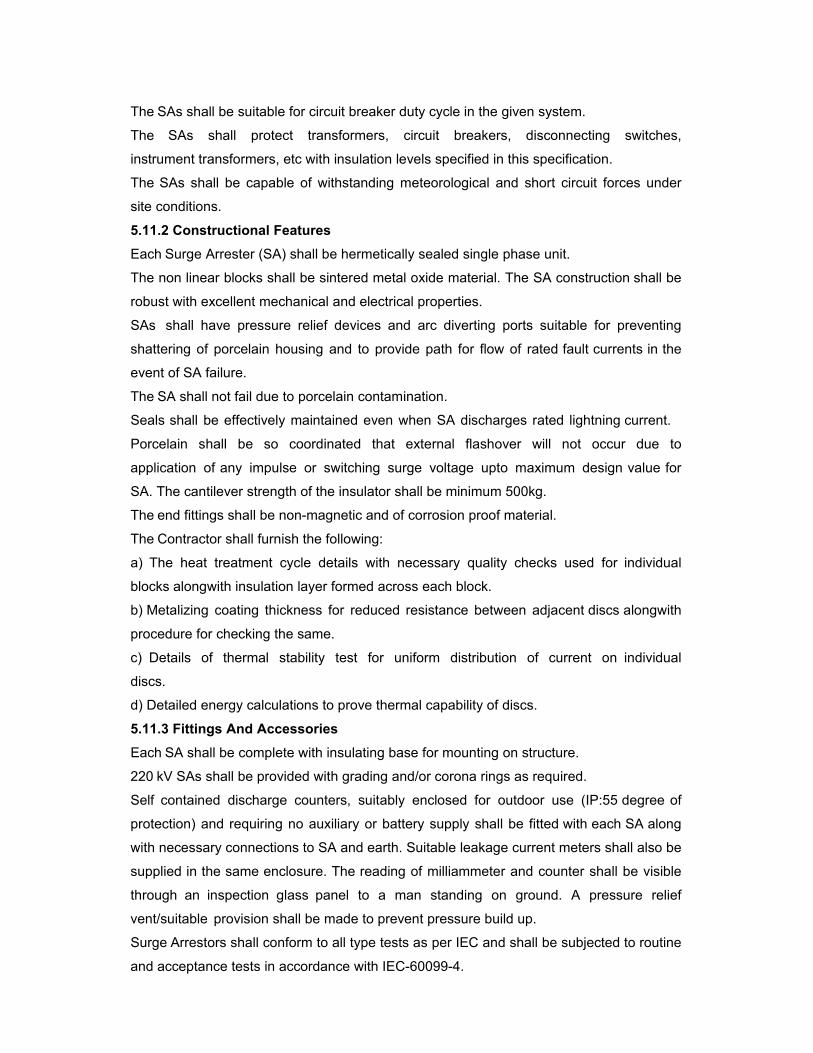
The SAs shall be suitable for circuit breaker duty cycle in the given system.
The SAs shall protect transformers, circuit breakers, disconnecting switches,
instrument transformers, etc with insulation levels specified in this specification.
The SAs shall be capable of withstanding meteorological and short circuit forces under
site conditions.
5.11.2 Constructional Features
Each Surge Arrester (SA) shall be hermetically sealed single phase unit.
The non linear blocks shall be sintered metal oxide material. The SA construction shall be
robust with excellent mechanical and electrical properties.
SAs shall have pressure relief devices and arc diverting ports suitable for preventing
shattering of porcelain housing and to provide path for flow of rated fault currents in the
event of SA failure.
The SA shall not fail due to porcelain contamination.
Seals shall be effectively maintained even when SA discharges rated lightning current.
Porcelain shall be so coordinated that external flashover will not occur due to
application of any impulse or switching surge voltage upto maximum design value for
SA. The cantilever strength of the insulator shall be minimum 500kg.
The end fittings shall be non-magnetic and of corrosion proof material.
The Contractor shall furnish the following:
a) The heat treatment cycle details with necessary quality checks used for individual
blocks alongwith insulation layer formed across each block.
b) Metalizing coating thickness for reduced resistance between adjacent discs alongwith
procedure for checking the same.
c) Details of thermal stability test for uniform distribution of current on individual
discs.
d) Detailed energy calculations to prove thermal capability of discs.
5.11.3 Fittings And Accessories
Each SA shall be complete with insulating base for mounting on structure.
220 kV SAs shall be provided with grading and/or corona rings as required.
Self contained discharge counters, suitably enclosed for outdoor use (IP:55 degree of
protection) and requiring no auxiliary or battery supply shall be fitted with each SA along
with necessary connections to SA and earth. Suitable leakage current meters shall also be
supplied in the same enclosure. The reading of milliammeter and counter shall be visible
through an inspection glass panel to a man standing on ground. A pressure relief
vent/suitable provision shall be made to prevent pressure build up.
Surge Arrestors shall conform to all type tests as per IEC and shall be subjected to routine
and acceptance tests in accordance with IEC-60099-4.
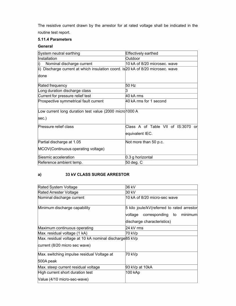
The resistive current drawn by the arrestor for at rated voltage shall be indicated in the
routine test report.
5.11.4 Parameters
General
System neutral earthing Effectively earthed Installation Outdoor i) Nominal discharge current 10 kA of 8/20 microsec. wave ii) Discharge current at which insulation coord. is
done
20 kA of 8/20 microsec. wave
Rated frequency 50 Hz Long duration discharge class 3 Current for pressure relief test 40 kA rms Prospective symmetrical fault current 40 kA rms for 1 second
Low current long duration test value (2000 micro
sec.)
1000 A
Pressure relief class Class A of Table VII of IS:3070 or
equivalent IEC.
Partial discharge at 1.05
MCOV(Continuous operating voltage)
Not more than 50 p.c.
Siesmic acceleration 0.3 g horizontal Reference ambient temp. 50 deg. C
a) 33 kV CLASS SURGE ARRESTOR
Rated System Voltage 36 kV Rated Arrester Voltage 30 kV Nominal discharge current 10 kA of 8/20 micro-sec wave
Minimum discharge capability 5 kilo joule/kV(referred to rated arrestor
voltage corresponding to minimum
discharge characteristics) Maximum continuous operating 24 kV rms Max. residual voltage (1 kA) 70 kVp Max. residual voltage at 10 kA nominal discharge
current (8/20 micro sec wave)
85 kVp
Max. switching impulse residual Voltage at
500A peak
70 kVp
Max. steep current residual voltage 93 kVp at 10kA High current short duration test
Value (4/10 micro-sec-wave)
100 kAp
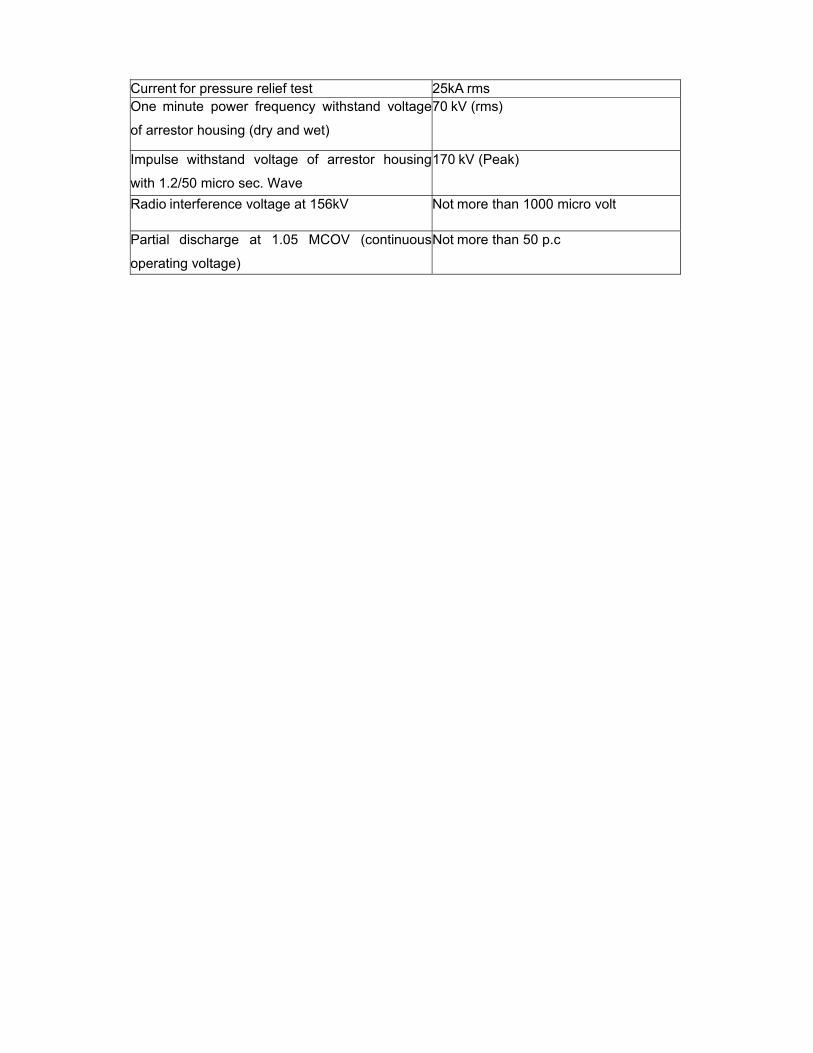
Current for pressure relief test 25kA rms One minute power frequency withstand voltage
of arrestor housing (dry and wet)
70 kV (rms)
Impulse withstand voltage of arrestor housing
with 1.2/50 micro sec. Wave
170 kV (Peak)
Radio interference voltage at 156kV Not more than 1000 micro volt
Partial discharge at 1.05 MCOV (continuous
operating voltage)
Not more than 50 p.c
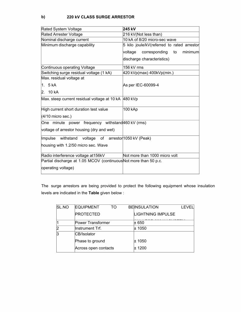
b) 220 kV CLASS SURGE ARRESTOR
The surge arrestors are being provided to protect the following equipment whose insulation
levels are indicated in the Table given below :
SL.NO EQUIPMENT TO BE
PROTECTED
INSULATION LEVEL
LIGHTNING IMPULSE
(kV ) FOR 220 kV SYSTEM1 Power Transformer ± 650 2 Instrument Trf. ± 1050 3 CB/Isolator
Phase to ground
Across open contacts
± 1050
± 1200
Rated System Voltage 245 kV Rated Arrester Voltage 216 kV(Not less than) Nominal discharge current 10 kA of 8/20 micro-sec wave Minimum discharge capability 5 kilo joule/kV(referred to rated arrestor
voltage corresponding to minimum
discharge characteristics)
Continuous operating Voltage 156 kV rms Switching surge residual voltage (1 kA) 420 kVp(max) 400kVp(min.) Max. residual voltage at
1. 5 kA
2. 10 kA
As per IEC-60099-4
Max. steep current residual voltage at 10 kA 480 kVp
High current short duration test value
(4/10 micro sec.)
100 kAp
One minute power frequency withstand
voltage of arrestor housing (dry and wet)
460 kV (rms)
Impulse withstand voltage of arrestor
housing with 1.2/50 micro sec. Wave
1050 kV (Peak)
Radio interference voltage at156kV Not more than 1000 micro volt Partial discharge at 1.05 MCOV (continuous
operating voltage)
Not more than 50 p.c.
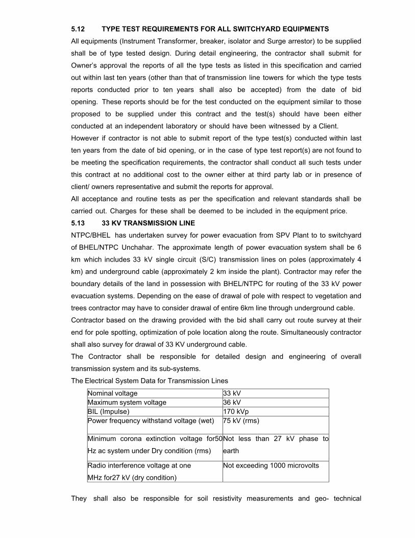
5.12 TYPE TEST REQUIREMENTS FOR ALL SWITCHYARD EQUIPMENTS
All equipments (Instrument Transformer, breaker, isolator and Surge arrestor) to be supplied
shall be of type tested design. During detail engineering, the contractor shall submit for
Owner’s approval the reports of all the type tests as listed in this specification and carried
out within last ten years (other than that of transmission line towers for which the type tests
reports conducted prior to ten years shall also be accepted) from the date of bid
opening. These reports should be for the test conducted on the equipment similar to those
proposed to be supplied under this contract and the test(s) should have been either
conducted at an independent laboratory or should have been witnessed by a Client.
However if contractor is not able to submit report of the type test(s) conducted within last
ten years from the date of bid opening, or in the case of type test report(s) are not found to
be meeting the specification requirements, the contractor shall conduct all such tests under
this contract at no additional cost to the owner either at third party lab or in presence of
client/ owners representative and submit the reports for approval.
All acceptance and routine tests as per the specification and relevant standards shall be
carried out. Charges for these shall be deemed to be included in the equipment price.
5.13 33 KV TRANSMISSION LINE
NTPC/BHEL has undertaken survey for power evacuation from SPV Plant to to switchyard
of BHEL/NTPC Unchahar. The approximate length of power evacuation system shall be 6
km which includes 33 kV single circuit (S/C) transmission lines on poles (approximately 4
km) and underground cable (approximately 2 km inside the plant). Contractor may refer the
boundary details of the land in possession with BHEL/NTPC for routing of the 33 kV power
evacuation systems. Depending on the ease of drawal of pole with respect to vegetation and
trees contractor may have to consider drawal of entire 6km line through underground cable.
Contractor based on the drawing provided with the bid shall carry out route survey at their
end for pole spotting, optimization of pole location along the route. Simultaneously contractor
shall also survey for drawal of 33 KV underground cable.
The Contractor shall be responsible for detailed design and engineering of overall
transmission system and its sub-systems.
The Electrical System Data for Transmission Lines
Nominal voltage 33 kV Maximum system voltage 36 kV BIL (Impulse) 170 kVp Power frequency withstand voltage (wet) 75 kV (rms)
Minimum corona extinction voltage for50
Hz ac system under Dry condition (rms)
Not less than 27 kV phase to
earth
Radio interference voltage at one
MHz for27 kV (dry condition)
Not exceeding 1000 microvolts
They shall also be responsible for soil resistivity measurements and geo- technical
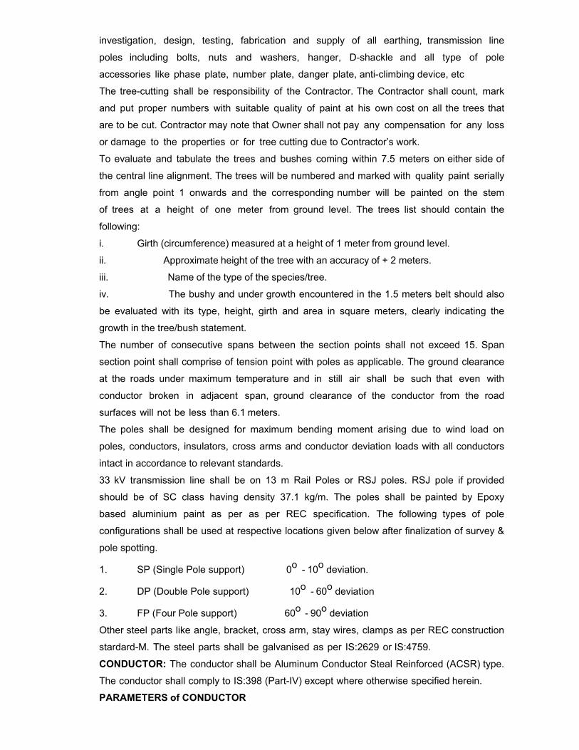
investigation, design, testing, fabrication and supply of all earthing, transmission line
poles including bolts, nuts and washers, hanger, D-shackle and all type of pole
accessories like phase plate, number plate, danger plate, anti-climbing device, etc
The tree-cutting shall be responsibility of the Contractor. The Contractor shall count, mark
and put proper numbers with suitable quality of paint at his own cost on all the trees that
are to be cut. Contractor may note that Owner shall not pay any compensation for any loss
or damage to the properties or for tree cutting due to Contractor’s work.
To evaluate and tabulate the trees and bushes coming within 7.5 meters on either side of
the central line alignment. The trees will be numbered and marked with quality paint serially
from angle point 1 onwards and the corresponding number will be painted on the stem
of trees at a height of one meter from ground level. The trees list should contain the
following:
i. Girth (circumference) measured at a height of 1 meter from ground level.
ii. Approximate height of the tree with an accuracy of + 2 meters.
iii. Name of the type of the species/tree.
iv. The bushy and under growth encountered in the 1.5 meters belt should also
be evaluated with its type, height, girth and area in square meters, clearly indicating the
growth in the tree/bush statement.
The number of consecutive spans between the section points shall not exceed 15. Span
section point shall comprise of tension point with poles as applicable. The ground clearance
at the roads under maximum temperature and in still air shall be such that even with
conductor broken in adjacent span, ground clearance of the conductor from the road
surfaces will not be less than 6.1 meters.
The poles shall be designed for maximum bending moment arising due to wind load on
poles, conductors, insulators, cross arms and conductor deviation loads with all conductors
intact in accordance to relevant standards.
33 kV transmission line shall be on 13 m Rail Poles or RSJ poles. RSJ pole if provided
should be of SC class having density 37.1 kg/m. The poles shall be painted by Epoxy
based aluminium paint as per as per REC specification. The following types of pole
configurations shall be used at respective locations given below after finalization of survey &
pole spotting.
1. SP (Single Pole support) 0o - 10o deviation.
2. DP (Double Pole support) 10o - 60o deviation
3. FP (Four Pole support) 60o - 90o deviation
Other steel parts like angle, bracket, cross arm, stay wires, clamps as per REC construction
stardard-M. The steel parts shall be galvanised as per IS:2629 or IS:4759.
CONDUCTOR: The conductor shall be Aluminum Conductor Steal Reinforced (ACSR) type.
The conductor shall comply to IS:398 (Part-IV) except where otherwise specified herein.
PARAMETERS of CONDUCTOR

a) Type Designation (Racoon) ACSR 7/4.09
b) Number and diameter of Aluminium 7/4.09 mm c) Total sectional area of Aluminium 79.20 sq.mm d) Overall diameter 12.30 mm e) Approximate weight 320 Kg/Km
f) Calculated d.c. resistance at 20 deg.C 0.3623 Ohms/Km g) Minimum UTS 27.74 KN
Wherever there is deviation in angle sufficient number of guys with support insulator
shall be provided to cater for uplift, depending upon direction of wind as REC specification
& construction standards or equivalent standard. Terminal poles shall be designed for
conductors strung on one side only. Wherever there is space constraints for guy wire, strut
poles may be used.
The material of pole shall comply IS: 802 “Code of practice for use of structural steel in
overhead transmission Line” and IS: 875. Clearance from ground, buildings, trees and
telephone lines shall be provided in conformity with the Indian Electricity Rules, 1956 as
amended upto date.
The design shall also be checked to cater for loads as per REC Standards for
transmission line on poles. Ground clearance shall be accordance to IS: 5613 Part II.
The poles shall be earthed as per REC specification and construction standards or IS: 3043
or equivalent standards. Earth wire of suitable size shall be used & the material of the wire
shall conform to IS 12776: 2002 Specification for Galvanized Strand for Earthing. All
conductors burred in earth and concrete shall be mild steel. All conductors above ground
level and earthing leads shall be galvanized steel.
Foundations shall be in accordance with IS: 4091-1979 and IS: 456. Foundations shall be of
pad and chimney type of concrete grade with minimum strength of concrete M20. For guy
wires Block foundation shall be provided. The factor of safety for foundations in normal
condition shall be 2.2. Mass concrete foundation is to be adopted in case of Black Cotton
Soil.
Any scope of design, supply and erection not covered in this specification but are
essential as per REC specification and construction standards for successful completion
(including testing & commissioning) are deemed to be included in the Contractor's scope.
The line insulator/ insulators shall consist either three (3) standard discs or one (1) pin type
insulator. Pin type insulator shall be used for pole type structure in vertical support mode
and as a pilot insulator for tension string in double circuit line. Contractor may note
insulators shall be made of electro-porcelain.
The size of disc insulator, the number to be used in different type of strings, their
electromechanical strength and minimum creepage distance shall be as follows.
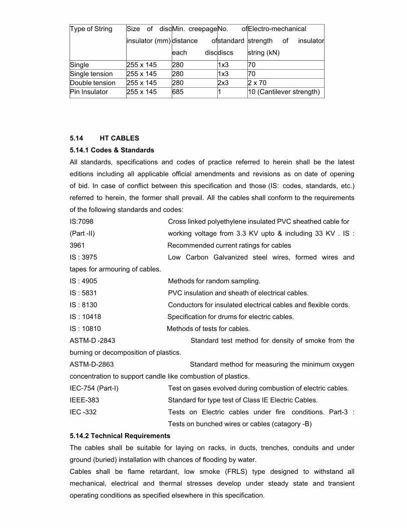
Type of String Size of disc
insulator (mm)
Min. creepage
distance of
each disc
No. of
standard
discs
Electro-mechanical
strength of insulator
string (kN)
Single 255 x 145 280 1x3 70 Single tension 255 x 145 280 1x3 70 Double tension 255 x 145 280 2x3 2 x 70 Pin Insulator 255 x 145 685 1 10 (Cantilever strength)
5.14 HT CABLES
5.14.1 Codes & Standards
All standards, specifications and codes of practice referred to herein shall be the latest
editions including all applicable official amendments and revisions as on date of opening
of bid. In case of conflict between this specification and those (IS: codes, standards, etc.)
referred to herein, the former shall prevail. All the cables shall conform to the requirements
of the following standards and codes:
IS:7098 Cross linked polyethylene insulated PVC sheathed cable for
(Part -II) working voltage from 3.3 KV upto & including 33 KV . IS :
3961 Recommended current ratings for cables
IS : 3975 Low Carbon Galvanized steel wires, formed wires and
tapes for armouring of cables.
IS : 4905 Methods for random sampling.
IS : 5831 PVC insulation and sheath of electrical cables.
IS : 8130 Conductors for insulated electrical cables and flexible cords.
IS : 10418 Specification for drums for electric cables.
IS : 10810 Methods of tests for cables.
ASTM-D -2843 Standard test method for density of smoke from the
burning or decomposition of plastics.
ASTM-D-2863 Standard method for measuring the minimum oxygen
concentration to support candle like combustion of plastics.
IEC-754 (Part-I) Test on gases evolved during combustion of electric cables.
IEEE-383 Standard for type test of Class IE Electric Cables.
IEC -332 Tests on Electric cables under fire conditions. Part-3 :
Tests on bunched wires or cables (catagory -B)
5.14.2 Technical Requirements
The cables shall be suitable for laying on racks, in ducts, trenches, conduits and under
ground (buried) installation with chances of flooding by water.
Cables shall be flame retardant, low smoke (FRLS) type designed to withstand all
mechanical, electrical and thermal stresses develop under steady state and transient
operating conditions as specified elsewhere in this specification.
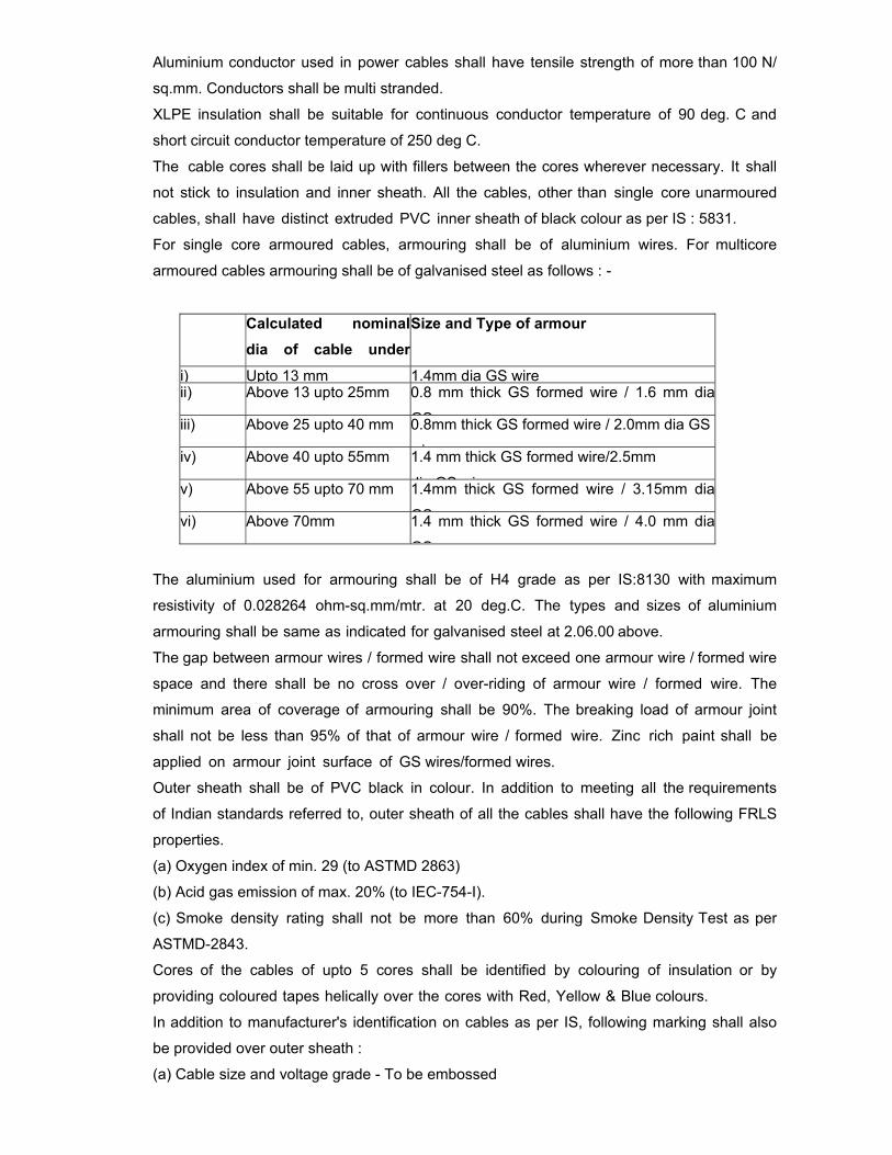
Aluminium conductor used in power cables shall have tensile strength of more than 100 N/
sq.mm. Conductors shall be multi stranded.
XLPE insulation shall be suitable for continuous conductor temperature of 90 deg. C and
short circuit conductor temperature of 250 deg C.
The cable cores shall be laid up with fillers between the cores wherever necessary. It shall
not stick to insulation and inner sheath. All the cables, other than single core unarmoured
cables, shall have distinct extruded PVC inner sheath of black colour as per IS : 5831.
For single core armoured cables, armouring shall be of aluminium wires. For multicore
armoured cables armouring shall be of galvanised steel as follows : -
Calculated nominaldia of cable under
Size and Type of armour
i) Upto 13 mm 1.4mm dia GS wireii) Above 13 upto 25mm 0.8 mm thick GS formed wire / 1.6 mm dia
GSiii) Above 25 upto 40 mm 0.8mm thick GS formed wire / 2.0mm dia GS
iiv) Above 40 upto 55mm 1.4 mm thick GS formed wire/2.5mm
di GS iv) Above 55 upto 70 mm 1.4mm thick GS formed wire / 3.15mm dia
GSvi) Above 70mm 1.4 mm thick GS formed wire / 4.0 mm dia
GS
The aluminium used for armouring shall be of H4 grade as per IS:8130 with maximum
resistivity of 0.028264 ohm-sq.mm/mtr. at 20 deg.C. The types and sizes of aluminium
armouring shall be same as indicated for galvanised steel at 2.06.00 above.
The gap between armour wires / formed wire shall not exceed one armour wire / formed wire
space and there shall be no cross over / over-riding of armour wire / formed wire. The
minimum area of coverage of armouring shall be 90%. The breaking load of armour joint
shall not be less than 95% of that of armour wire / formed wire. Zinc rich paint shall be
applied on armour joint surface of GS wires/formed wires.
Outer sheath shall be of PVC black in colour. In addition to meeting all the requirements
of Indian standards referred to, outer sheath of all the cables shall have the following FRLS
properties.
(a) Oxygen index of min. 29 (to ASTMD 2863)
(b) Acid gas emission of max. 20% (to IEC-754-I).
(c) Smoke density rating shall not be more than 60% during Smoke Density Test as per
ASTMD-2843.
Cores of the cables of upto 5 cores shall be identified by colouring of insulation or by
providing coloured tapes helically over the cores with Red, Yellow & Blue colours.
In addition to manufacturer's identification on cables as per IS, following marking shall also
be provided over outer sheath :
(a) Cable size and voltage grade - To be embossed
(b) Word 'FRLS' at every 5 metre - To be embossed
(c) Sequential marking of length of the cable in metres at every one metre. -To be embossed
/ printed
The embossing / printing shall be progressive, automatic, in line and marking shall be
legible and indelible.
All cables shall meet the fire resistance requirement as per IEEE - 383 with cable
installations made in accordance with 'Flammability Test' and as per Category-B of IEC 332
Part -3.
Allowable tolerances on the overall diameter of the cables shall be +\-2 mm maximum over
the declared value in the technical data sheets.
In plant repairs to the cables shall not be accepted. Pimples, fish eye, blow holes etc. are
not acceptable.
The cross-sectional area of the metallic screen strip/tape shall be considered in design
calculations.
Cable selection & sizing
HT cables shall be sized based on the following considerations:
a) Rated current of the equipment
b) The voltage drop in the cable, during motor starting condition, shall be limited to
10% and during full load running condition, shall be limited to 3% of the rated voltage
c) Short circuit withstand capability
Derating Factors
Derating factors for various conditions of installations including the following shall be
considered while selecting the cable sizes:
a) Variation in ambient temperature for cables laid in air
b) Grouping of cables
c) Variation in ground temperature and soil resistivity for buried cables.
Cable lengths shall be considered in such a way that straight through cable joints are
avoided.
Cables shall be armoured type if laid directly buried.
5.14.3 Constructional Feature
19/33 KV Grade Cables
Cables shall conform to IS : 7098 Part - II. These cablesshall have mutli- stranded,
compacted circular, aluminium conductors, XLPE insulated, metallic screened suitable for
carrying the system earth fault current, PVC outersheathed. The conductor screen and
insulation screen shall both be of extruded semiconducting compound and shall be
applied along with the XLPE insulation in a single operation of triple extrusion process so as
to obtain continuously smooth interfaces. Method of curing for 19/33KV cables shall be
“dry curing / gas curing”. The metallic screen of each core shall consist of copper tape
with minimum overlap of 20%. However for single core armoured cables, the armouring
shall constitute the metallic part of the screening. The eccentricity of insulation shall be
calculated as
tmax -tmin ----------------------- x 100 tmax and the ovality shall be calculated as
dmax -dmin ---------------- x 100 dmax Where tmax/tmin is the maximum/minimum thickness of insulation and dmax/dmin is the
maximum / minimum diameter of the core.
5.14.4 Cable Drums
Cables shall be supplied in non returnable wooden or steel drums of heavy construction.
The surface of the drum and the outer most cable layer shall be covered with water proof
cover. Both the ends of the cables shall be properly sealed with heat shrinkable PVC/
rubber caps secured by 'U' nails so as to eliminate ingress of water during
transportation, storage and erection. Wood preservative anti-termite treatment shall be
applied to the entire drum. Wooden drums shall comply with IS: 10418.
Each drum shall carry manufacturer's name, purchaser's name, address and contract
number, item number and type, size and length of cable and net gross weight stencilled on
both sides of the drum. A tag containing same information shall be attached to the leading
end of the cable. An arrow and suitable accompanying wording shall be marked on one end
of the reel indicating the direction in which it should be rolled.
5.14.5 Type, Routine And Acceptance Tests
a) The type tests shall be carried out in presence of the employer’s representative, for
which minimum 15 days notice shall be given by the contractor. The contractor shall obtain
the employer’s approval for the type test procedure before conducting the type test. The
type test procedure shall clearly specify the test set–up, instruments to be used, procedure,
acceptance norms, recording of different parameters, interval of recording, precautions to
be taken etc. for the type test(s) to be carried out.
b) In case the contractor has conducted such specified type test(s) within last ten years as
on the date of bid opening, he may submit during detailed engineering the type test reports to
the owner for waival of conductance of such type test(s). These reports should be for the
tests conducted on the equipment similar to those proposed to be supplied under this
contract and test(s) should have been either conducted at an independent laboratory or
should have been witnessed by a client. The owner reserves the right to waive conducting
of any or all the specified type test(s) under this contract. In case type tests are waived, the
type test charges shall not be payable to the contractor.
c) All acceptance and routine tests as per the specification and relevant standards shall be
carried out. Charges for these shall be deemed to be included in the equipment price
d) The type test reports once approved for any projects shall be treated as reference.
For subsequent projects of BHEL/NTPC, an endorsement sheet will be furnished by the
manufacturer confirming similarity and “No design Change”. Minor changes if any shall be
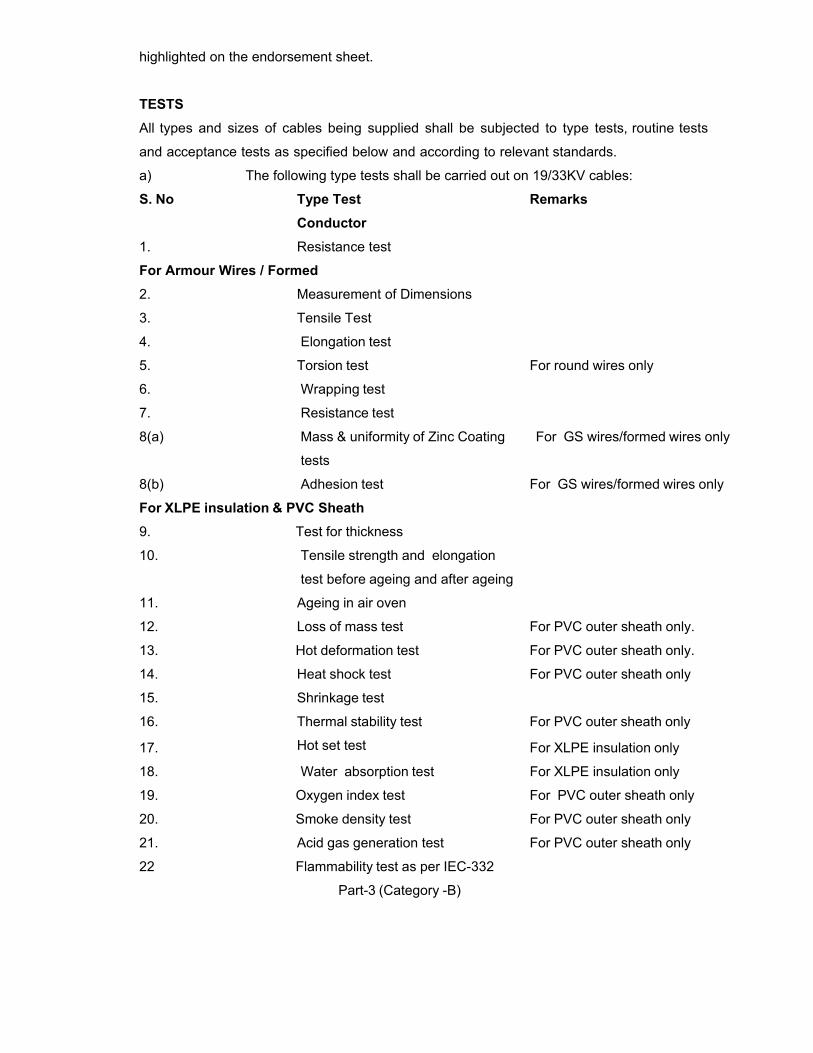
highlighted on the endorsement sheet.
TESTS
All types and sizes of cables being supplied shall be subjected to type tests, routine tests
and acceptance tests as specified below and according to relevant standards.
a) The following type tests shall be carried out on 19/33KV cables:
S. No Type Test Remarks Conductor 1. Resistance test
For Armour Wires / Formed 2. Measurement of Dimensions
3. Tensile Test
4. Elongation test
5. Torsion test For round wires only
6. Wrapping test
7. Resistance test
8(a) Mass & uniformity of Zinc Coating For GS wires/formed wires only
tests
8(b) Adhesion test For GS wires/formed wires only
For XLPE insulation & PVC Sheath
9. Test for thickness
10. Tensile strength and elongation
test before ageing and after ageing
11. Ageing in air oven
12. Loss of mass test For PVC outer sheath only.
13. Hot deformation test For PVC outer sheath only.
14. Heat shock test For PVC outer sheath only
15. Shrinkage test
16. Thermal stability test For PVC outer sheath only
17. Hot set test For XLPE insulation only
18. Water absorption test For XLPE insulation only
19. Oxygen index test For PVC outer sheath only
20. Smoke density test For PVC outer sheath only
21. Acid gas generation test For PVC outer sheath only
22 Flammability test as per IEC-332
Part-3 (Category -B)
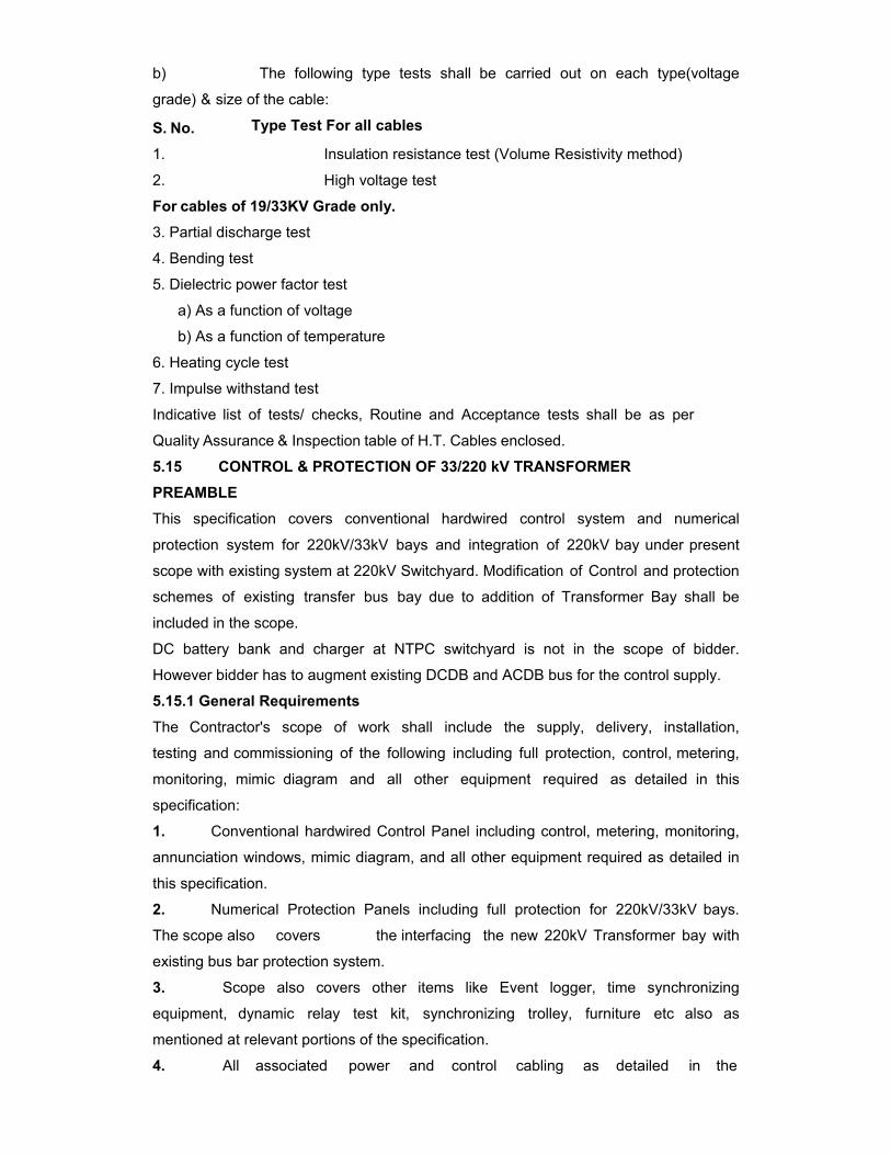
b) The following type tests shall be carried out on each type(voltage
grade) & size of the cable:
S. No. Type Test For all cables
1. Insulation resistance test (Volume Resistivity method)
2. High voltage test
For cables of 19/33KV Grade only. 3. Partial discharge test
4. Bending test
5. Dielectric power factor test
a) As a function of voltage
b) As a function of temperature
6. Heating cycle test
7. Impulse withstand test
Indicative list of tests/ checks, Routine and Acceptance tests shall be as per
Quality Assurance & Inspection table of H.T. Cables enclosed.
5.15 CONTROL & PROTECTION OF 33/220 kV TRANSFORMER
PREAMBLE
This specification covers conventional hardwired control system and numerical
protection system for 220kV/33kV bays and integration of 220kV bay under present
scope with existing system at 220kV Switchyard. Modification of Control and protection
schemes of existing transfer bus bay due to addition of Transformer Bay shall be
included in the scope.
DC battery bank and charger at NTPC switchyard is not in the scope of bidder.
However bidder has to augment existing DCDB and ACDB bus for the control supply.
5.15.1 General Requirements
The Contractor's scope of work shall include the supply, delivery, installation,
testing and commissioning of the following including full protection, control, metering,
monitoring, mimic diagram and all other equipment required as detailed in this
specification:
1. Conventional hardwired Control Panel including control, metering, monitoring,
annunciation windows, mimic diagram, and all other equipment required as detailed in
this specification.
2. Numerical Protection Panels including full protection for 220kV/33kV bays.
The scope also covers the interfacing the new 220kV Transformer bay with
existing bus bar protection system.
3. Scope also covers other items like Event logger, time synchronizing
equipment, dynamic relay test kit, synchronizing trolley, furniture etc also as
mentioned at relevant portions of the specification.
4. All associated power and control cabling as detailed in the
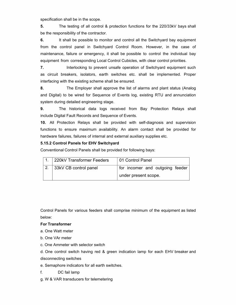
specification shall be in the scope.
5. The testing of all control & protection functions for the 220/33kV bays shall
be the responsibility of the contractor.
6. It shall be possible to monitor and control all the Switchyard bay equipment
from the control panel in Switchyard Control Room. However, in the case of
maintenance, failure or emergency, it shall be possible to control the individual bay
equipment from corresponding Local Control Cubicles, with clear control priorities.
7. Interlocking to prevent unsafe operation of Switchyard equipment such
as circuit breakers, isolators, earth switches etc. shall be implemented. Proper
interfacing with the existing scheme shall be ensured.
8. The Employer shall approve the list of alarms and plant status (Analog
and Digital) to be wired for Sequence of Events log, existing RTU and annunciation
system during detailed engineering stage.
9. The historical data logs received from Bay Protection Relays shall
include Digital Fault Records and Sequence of Events.
10. All Protection Relays shall be provided with self-diagnosis and supervision
functions to ensure maximum availability. An alarm contact shall be provided for
hardware failures, failures of internal and external auxiliary supplies etc.
5.15.2 Control Panels for EHV Switchyard
Conventional Control Panels shall be provided for following bays:
Control Panels for various feeders shall comprise minimum of the equipment as listed
below:
For Transformer a. One Watt meter
b. One VAr meter
c. One Ammeter with selector switch
d. One control switch having red & green indication lamp for each EHV breaker and
disconnecting switches
e. Semaphore indicators for all earth switches.
f. DC fail lamp
g. W & VAR transducers for telemetering
1. 220kV Transformer Feeders 01 Control Panel
2. 33kV CB control panel for incomer and outgoing feeder
under present scope.
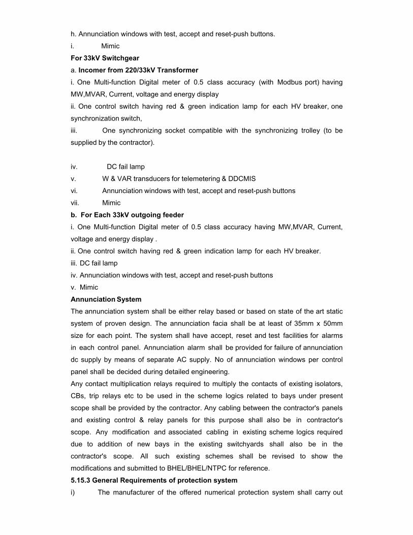
h. Annunciation windows with test, accept and reset-push buttons.
i. Mimic
For 33kV Switchgear a. Incomer from 220/33kV Transformer i. One Multi-function Digital meter of 0.5 class accuracy (with Modbus port) having
MW,MVAR, Current, voltage and energy display
ii. One control switch having red & green indication lamp for each HV breaker, one
synchronization switch,
iii. One synchronizing socket compatible with the synchronizing trolley (to be
supplied by the contractor).
iv. DC fail lamp
v. W & VAR transducers for telemetering & DDCMIS
vi. Annunciation windows with test, accept and reset-push buttons
vii. Mimic
b. For Each 33kV outgoing feeder i. One Multi-function Digital meter of 0.5 class accuracy having MW,MVAR, Current,
voltage and energy display .
ii. One control switch having red & green indication lamp for each HV breaker.
iii. DC fail lamp
iv. Annunciation windows with test, accept and reset-push buttons
v. Mimic
Annunciation System
The annunciation system shall be either relay based or based on state of the art static
system of proven design. The annunciation facia shall be at least of 35mm x 50mm
size for each point. The system shall have accept, reset and test facilities for alarms
in each control panel. Annunciation alarm shall be provided for failure of annunciation
dc supply by means of separate AC supply. No of annunciation windows per control
panel shall be decided during detailed engineering.
Any contact multiplication relays required to multiply the contacts of existing isolators,
CBs, trip relays etc to be used in the scheme logics related to bays under present
scope shall be provided by the contractor. Any cabling between the contractor's panels
and existing control & relay panels for this purpose shall also be in contractor's
scope. Any modification and associated cabling in existing scheme logics required
due to addition of new bays in the existing switchyards shall also be in the
contractor's scope. All such existing schemes shall be revised to show the
modifications and submitted to BHEL/BHEL/NTPC for reference.
5.15.3 General Requirements of protection system
i) The manufacturer of the offered numerical protection system shall carry out
complete engineering, testing & commissioning at site of the offered protections
including the associated relay & protection panels.
ii) The protection system shall be arranged to provide two independent, high
performance and reliable systems with separate monitored DC supplies, separate
CT/VT cores, separate cables and trip relays to obtain 100% redundancy. Associated
trip relays of the two systems shall be separate, having sufficient number of contacts
for all the functions. Each protection shall energize both trip coils of the circuit breakers
to be tripped.
iii) All numerical relays shall be supplied with all protection functions / features in
disabled condition. Relevant features / protection functions shall be enabled at the
time of commissioning at site as per approved logic and relay settings.
iv) The total critical fault clearance time from fault initiation in any part of the
system shall be 80 m sec for phase to phase fault in the generator- transformer
unit and for phase to phase and phase to earth faults in the EHV system inter-
connection.
v) Modification and interfacing with the existing protection scheme, including
supply of any hardware/ software, such as bus bar protection shall be in contractor’s
scope
5.15.4 Operational Requirements for Numerical Relays and Auxiliary Relays
i) All protection relays to be supplied under this package shall be Numerical
type. The communication protocol for major Transformer protections such as differential
and multifunctional O/C & E/F relays shall be IEC61850.
ii) All numerical relays, auxiliary relays and devices shall be of latest version,
reputed make and types proven for the application, satisfying requirement covered
elsewhere and shall be subject to Owner’s approval. Relays and timers shall have
appropriate setting ranges, accuracy, resetting ratio, transient overreach and other
characteristics to provide required sensitivity to the satisfaction of the Owner.
iii) Numerical relays shall be suitable for efficient and reliable operation of the
protection scheme. Necessary auxiliary relays, timers, trip relays, etc. required for
complete scheme, interlocking, alarm, logging, etc. shall be provided. No control
relay, which shall trip the circuit breaker when relay is de-energized, shall be
employed in the circuits.
iv) Relays shall be provided with self-reset contacts except for the trip lockout
relays, which shall have manual reset facility. Suitable measures shall be provided to
ensure that transients present in CT & VT connections due to extraneous sources in
EHV system do not cause damage to the numerical and other relays. CT saturation
shall not cause mal-operation of numerical relays.
v) Except for event logging, alarm and annunciation type of non-trip functions,
protective relay contact multiplier relay shall be high speed trip relay only.
vi) Only DC/DC converters shall be provided in the solid state devices /
numerical relays wherever necessary to provide a stable auxiliary supply for relay
operation. DC batteries in protective relays and timers necessary for relay operation
shall not be acceptable. Equipment shall be protected against voltage spikes in
auxiliary DC supply.
vii) Pick up range of the Binary inputs shall be minimum 70 V DC /AC.
viii) The numerical relays offered shall have self-diagnostic features to reduce the
down time of the relay and provide useful diagnostic information on detection of an
internal fault to speed up the maintenance. Necessary support documentation
explaining the self-diagnostic features of the numerical relays in detail shall be
furnished for owner’s use.
ix) The numerical protection shall have continuous self-monitoring & cyclical test
facilities. The internal clock of all the numerical relays being supplied under this
package shall be synchronized through the GPS Time Synchronizing System, under
present scope. A timing accuracy of 1ms shall be achieved for all the numerical relays.
x) The sampling rate of analog inputs, the processing speed and processing
cycle of digital values shall be selected so as to achieve the operating times of
various protection functions specified.
xi) Display of various measured parameters during normal as well as fault
condition on segregated phase basis shall be provided. In addition to a local HMI,
Numerical relays shall also have LEDs and back lit LCD screen shall be provided for
visual indication and display of messages related to major trips / alarms generated in
the relays.
xii) All the numerical relays shall have adequate processor capability to carry out
programmable scheme logics (PSL) required for implementing approved protection and
control schemes over and above its inbuilt protection functions algorithm.
xiii) The numerical relays shall be provided with built-in disturbance recorder. The
data from DR function shall be available in IEEE/COMTRADE format and compatible
with the dynamic relay test system being supplied in this contract.
5.15.5 EHV Circuit-breaker Protection
Each 220kV circuit breaker being supplied under this package in the switchyard shall be
provided with following protection functions:
i) Local Breaker Back up Protection Function: Duplicated LBB protection
function shall be provided for each 220kV circuit breaker supplied under this package
The LBB function as a built-in function of bus bar protection is also acceptable
provided it meets all the requirements specified for the LBB function. In addition, the
LBB protection function shall meet following criteria:
- Be three pole type having three single phase units
- Shall operate for stuck breaker conditions
- Have an operating/resetting time each of less than 15 ms.
- The LBB function shall be initiated by external trip contacts from
various protection functions and after a set time delay shall energize the trip bus in the
bus bar protection scheme on which the stuck breaker is connected for tripping of all
breakers connected to the particular bus. In addition, an instantaneous repeat trip command from LBB shall be given to the primary breaker through a separate trip relay. The interlocking between different relays to achieve the LBB functionality
shall be achieved by hard-wired logic.
- Have a setting range of 5 to 80% of rated current
- Have a continuous thermal withstand of 2 times rated current irrespective of the
setting.
- Have time delay feature with a continuously adjustable setting range of 0.1 to 1 s.
- Shall be an individual phase comprehensive scheme.
- Shall not operate during the single-phase auto-reclosing period.
- Shall provide end-fault protection that initiates a direct transfer trip to the remote end
upon the detection of a loss of SF6
ii) Trip Coil Supervision: A Trip Coil supervision function shall be provided for
each lockout trip relay and each of the circuit-breaker trip coils. It shall incorporate both the pre-close and post-close supervision of trip coils and associated trip circuits.
An audible alarm shall be given in the event of operation of trip coil supervision
function. It shall have a time delay on drop- off of not less than 200ms.
iii) DC Supply Supervision
iv) Pole Discrepancy Protection for each 220kV CB under this package. v) High Speed Trip Relays supplied under this package shall be:
- With operating time of less than 10ms.
- With reset time of less than 20ms.
- Provided with operation indicator for each element/coil.
- Have adequate contacts to meet the scheme requirements of trip, interlock, LBB,
auto-reclose, DR, fault locator, etc.
- Hand reset or self reset, depending on the application. Further, the trip relays shall be
provided with a feature to receive manual reset command from engineering workstation
located in remote.
5.15.6 Interface with Existing Bus Bar protection
The contractor shall provide all interfacing requirements with the existing 220 kV bus
bar protection scheme at switchyard of BHEL/NTPC Unchahar. All trip relays,
multiplication relays, CT switching relays (if required), Weather Proof Relay Panels
(if provided in existing scheme), cable and associated cabling required to achieve this
interfacing shall be provided under this package.
Contractor to take note of existing B/B protection relay at Unchahar. Details of
existing system shall be given to the successful contractor during detail engineering.
TRANSFORMER PROTECTION
Numerical Protection system offered for the transformer should be such that it
provides a comprehensive protection for all types of faults and abnormal operating
conditions. Further, the numerical protection system shall be configured into a
duplicated protection system such that one protection system shall always be
available to detect and operate for any type of fault in the transformer under
condition of failure of other numerical protection system or of associated DC supply of
other numerical system.
33KV FEEDER PROTECTION:
Overcurrent and earth fault protection and any special protection for unearthed
system required shall also be provided.
PROTECTIONS FOR 220/33KV TRANSFORMER
i) Transformer Differential Protection (87 T)
ii) Restricted Earth Fault Protection on HV and LV winding (64RHV / 64RLV)
iii) Directional Over current & Earth Fault Protection on LV side (67/67N)
iv) Backup Over current Protection on HV side (50/51)
v) Back up earth fault protections on LV side on neutral CT (51N)
vi) Transformer Over fluxing (99)
vii) Multiplication relays for trip of Buchholtz/ Pressure Relief Device /
Sudden Pressure Relay, Fire protection etc.
Differential, REF and Back-up protection of transformer shall be realized in separate
numerical relays with Differential, Back-up E/F in one channel and REF, Back-up O/C
in another channel.
TRANSFORMER DIFFERENTIAL PROTECTION (87) (a) Shall be of numerical type and shall have continuous self-monitoring and
diagnostic features;
(b) Shall be three-pole type, with faulty phase identification/indication. The operating
time of the relay shall not be greater than 30ms at 5 times the setting.
(c) Shall be stable for magnetizing inrush currents and shall be stable under normal
over-fluxing conditions. Magnetizing inrush stability shall not be achieved through the
use of an intentional time delay;
(d) Shall have an internal feature in the relay to take care of the angle and ratio
correction;
(e) Shall have a disturbance recording feature to record the analogue form of
instantaneous values of the current in all three windings (i.e. nine analog channels)
during faults and disturbances for the pre-fault and post-fault periods. The
disturbance recorder shall have the facility to record the following external digital
channel signals in addition to the digital signals pertaining to the differential relay
itself:
- HV breaker (main and transfer) status
- LV breaker status
- On-load tap-changer position
- Buchholtz alarm/trip
- Alarm/trip of transformer/reactor on winding temperature/oil temperature/ pressure
relief
The necessary hardware and software for downloading the data captured by the
disturbance recording function to a personal computer available in the substation shall
be included in the scope.
Transformer Restricted Earth Fault Protection (64R) (a) Shall be single pole type
(b) Shall be of voltage operated high impedance type
(c) Shall have a current setting range of 5 – 20 % or 10-40% of 1A as applicable.
(d) Shall be tuned to the system frequency
(e) Shall have suitable non-linear resistor to limit the peak voltage
Transformer Backup Over current Protection (50/51) with high set feature
(a) Shall be triple pole type
(b) Shall be of definite time characteristic & have built-in timer with suitable range
(c) Shall have a low transient, overreach high-set instantaneous unit
(d) Shall have an adjustable setting range for current and time setting
(e) Shall include hand-reset indication per phase.
Transformer Backup Earth Fault Protection (51LN) (a) Shall be single pole type
(b) Shall be of definite time over current type
(c) Shall have an adjustable setting range of 20-80% of rated current as applicable
and 0.3 to 3.0 sec. time delay
(d) Shall be provided with operation indicator
Directional Back up Over Current and E/F Protection (67/67N) (a) Shall have three over current and one earth fault element(s) which shall be either
independent or composite unit(s) and shall have built-in timer with suitable range;
(b) shall be of numerical type;
(c) the scheme shall include the necessary VT fuse failure relays for alarm purposes;
(d) the over current function shall:
- have a low transient, overreach high-set instantaneous unit;
- include hand-reset indication.
(e) the earth fault function shall:
- have a low transient, over-reach high set instantaneous unit;
-include hand reset indication;

- Include the necessary separate interposing voltage transformers or have an
internal feature in the relay for open delta voltage to the relay.
The ranges mentioned above are only indicative only and the final ranges shall be
finalized during detailed engineering.
Transformer over fluxing Protection (99) (a) Operate on the principle of voltage to frequency ratio.
(b) Have inverse time characteristics compatible to transformer over fluxing withstand
capability and also a separate high set feature.
(c) Provide an independent alarm with continuously adjustable time delay.
(d) Tripping time shall be governed by V/ F Vs time characteristic of the relay.
(e) Have a set of characteristics for various multiplier settings.
(f) Have a resetting ratio of 98% or better.
5.15.7 Panels
-The dimensions of control / relay panel shall be matching with the existing panels at
site, details of which shall be furnished during the detailed engineering.
-Each panel shall be provided with a 240V AC fluorescent lighting fixture controlled
by door switch as well as a 5A, 240V AC switch-socket unit.
-Synchronizing socket matching with the existing trolley shall be provided else
separate synchronising trolley shall be provided.
-Shall be provided with necessary arrangements for receiving, distributing, isolating
and fusing of AC & DC supplies for various circuits for control, signaling, lighting,
interlocking, etc. Selection of main and sub-circuit fuse rating shall ensure selective
clearance of the sub-circuit faults.
-Voltage circuits for protection and metering shall be protected by fuses. Suitable
fuse failure relays shall be provided to give an alarm for voltage circuits of
protection/metering. Voltage selection scheme based on relays shall be provided for
meters wherever possible.
-The DC supplies at the individual relay and protection panels shall be monitored by
suitable relays and failure of DC supplies shall be annunciated.
-All equipments mounted on front and rear side of the panels should shall have
individual name-plates with equipment designation engraved.
-Each panel shall also have circuit/feeder designation name plat
(a) All panels shall be free standing, floor mounting type and completely metal
enclosed. Cable entries shall be from the bottom. Panels shall be of IP 31 class or
better.
(b) Panels shall have removable gland plates with glands made of brass and shall
be suitable for armoured cables.
(c) Panels shall be painted. The colour of paint for exterior of the panels shall be
matching with other panels in the station & shall be decided during detail engineering

(d) Panels shall have a lockable front Plexiglas door and a swing frame.
Panels shall facilitate direct access to any component
(e) All equipment mounted on the panels shall have individual name- plates with
equipment designation engraved.
(f) Internal wiring to be connected to external equipment shall terminate on terminal
blocks. Shall have 20% terminals as spare terminals in each panel.
(g) The terminal blocks for CTs and VTs shall be provided with test links and
isolating facilities. The CT terminal blocks shall be provided with short circuiting and
earthing facilities.
(h) Contractor shall be solely responsible for completeness and correctness of all the
wiring, and for proper functioning of the connected equipment.
5.15.8 Earthing (a) The panels shall be equipped with an earth bus of at least 50x6mm2 galvanized
steel flat bar or equivalent copper.
(b) Earth buses of adjoining panels shall be connected for continuity. The
continuous earth bus so formed shall be connected to the main earth grid at one end
only.
(c) All metallic cases of the mounted equipment shall be separately connected to
the earth bus by 2.5mm2 copper wires. No loops in the earth wiring shall be permitted.
(d) CT/VT neutral secondary shall only be earthed at the terminal block of the panel
through links, such that the earthing of one group may be removed without disturbing
others.
(e) An independent Electronic Earth System shall be provided as per contractor’s
standard. The electronic earth shall be connected to the substation earth mat through a
dedicated riser.
5.15.9 Control Cabling Philosophy
(a) Each three phase secondary core of each CT/VT shall be brought to the associated
relay panel through independent cables.
(b) Duplicated cores with at least 2 x 2.5 sq.mm2 CU/equivalent core cross-sectional
area per connection shall be used for connection of all CT/VT circuits.
(c) VT leads used for tariff metering shall have an equivalent core cross-sectional
area of at least 10 mm2 CU/equivalent per phase/neutral connection.
(d) Duplicate channels of protection shall have independent cables for tripping, DC
supply, etc. Duplicated cores shall be used for ALL closing/tripping commands and
interlocking signals involving long (more than 500 m) cable lengths.
(e) For the following applications multiple cores with at least 2 x 2.5 mm2 CU /
equivalent core cross - sectional area per connection shall be used:
-DC supply to Bay Marshalling box
-DC supply to circuit-breaker cubicle
-DC looping for closing and tripping circuits of circuit-breaker
(f) All the interconnections (both AC/DC) within the switchyard and between
switchyard and other systems required for the successful implementation of the control,
interlocks and protection schemes under present package, as shown in the tender
drawings for control & protection SLD, shall be in the scope of the contractor. Such
interconnections between switchyard and other system shall include but not limited to
the following:
-Extension of switchyard bus voltages to Control & Protection Panels.
- Necessary interconnections for the Inter tripping / closing interlocking between
upstream and down stream systems of transformer.
- Necessary interconnections from transformer MB to RTCC / BCU for OLTC control &
monitoring.
- Necessary interfacing between Transformer MBs & Control Panel for various
Transformer monitoring systems and fire protection system shall also be in contractor’s
scope
- Any screened cable required for connecting 4-20 mA
analog signals.
- Cables for interfacing different protections & control schemes of the new bay
to the existing 220kV SWYD protections & schemes.
(g) Spare cores shall be provided as per following norms:
- Up to 3-core cable - Nil
- 5 Core Cable - Min. 1 core
- 7 to 14 core cables - Min. 2 cores
- More than 14 core - Min. 3 cores
Mimic Diagram
Colour mimic diagram showing the exact representation of the system shall be
provided in front of the control panel.
Mimic colour shall be matching with that of the existing 220kV control panels and
the details shall be furnished by the Owner during detailed engineering.
Auxiliary Equipment All control and instrumentation switches shall be rotary operated type with escutcheon
plate showing the operating position and circuit designation. All switches shall be flush
mounted. Handles of different shapes shall be provided as approved by Owner. Control
switches for breaker or disconnecting switch shall be of spring return to neutral type,
while all other shall be stay-put type all the synchronizing switches shall have a
removable common handle, removable only in off-position.
Lockable type switches shall be provided for same application as specified by the
Owner. The contact combination and their operation shall ensure completeness of the
scheme function and interlock requirements. Contact ratings of the switches shall be as
per relevant standards. Contacts shall be spring assisted and contact faces shall be
made pure silver.
Cluster type LED indicating lamps shall be provided.
Position indicators for the earth switches of semaphore type shall be provided as
specified in the mimic diagram.
It shall be suitable for DC operation.
Indicating Instruments
a) Shall conform to IS: 1248
b) Shall be suitable for the instrument transformers as indicated in the drawings
enclosed and shall be calibrated to read directly the primary quantities.
c) Shall be calibrated and adjusted at works and shall also be tested and calibrated at
site before commissioning. All these instruments shall be flush mounted.
d) Shall be transducer operated, having 240 deg. scale and a dial of 96x96 mm2,
have an accuracy of 1.5 class and resolution of at least 50% of accuracy class
e) Current coils shall be 120% of rated current and 10 times for 0.5 sec. without
loosing accuracy.
Recording Instruments (if applicable) The recorders shall
a. Shall be draw out type and suitable for back connection.
b. Provision for automatic shorting of CT leads shall be provided when recorder is
drawn out.
c. Shall be dual pen employing potentiometric servo principle.
d. Shall record continuously on a calibrated 100mm (min) wide plain paper chart.
e. The accuracy of the recording shall be 0.5 % span. Full span response time shall not
be less than 2 sec.
f. Shall include an inverter for operating on AC supply in case of DC supply failure.
Switching shall be automatic.
Transducers
a) Shall conform to IEC: 688-1.
b) The output of the transducers shall be 4-20mA/0-10mA/10-0-10mA dc as
necessary for the instruments.
c) Accuracy class shall be 0.5 or better except for frequency transducer, which shall
have an accuracy of 0.2.
d) Summation transducer shall be suitable for taking multiple inputs from individual
MW/MVAR transducers.
e) Shall have dual output. One output shall be used for the indicating
instrument/recorder provided and other shall be wired up to terminal block of the panel
for Owner's use in future.
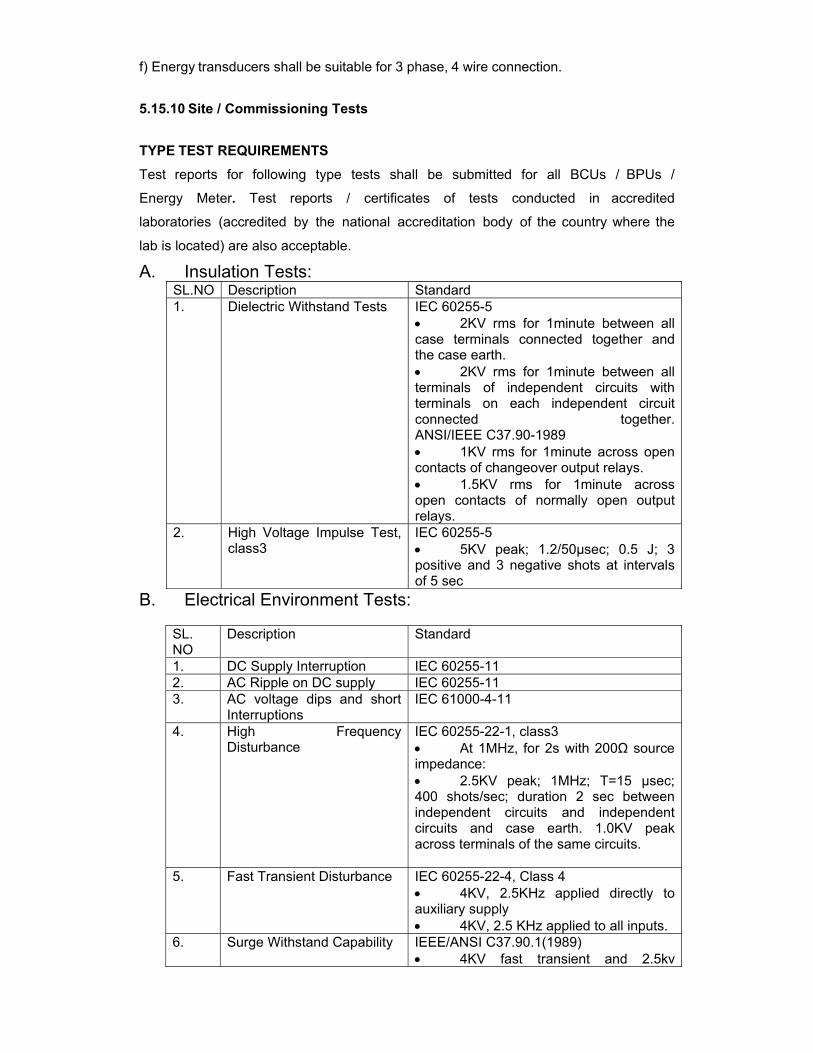
f) Energy transducers shall be suitable for 3 phase, 4 wire connection.
5.15.10 Site / Commissioning Tests TYPE TEST REQUIREMENTS
Test reports for following type tests shall be submitted for all BCUs / BPUs /
Energy Meter. Test reports / certificates of tests conducted in accredited
laboratories (accredited by the national accreditation body of the country where the
lab is located) are also acceptable.
A. Insulation Tests: SL.NO Description Standard 1. Dielectric Withstand Tests IEC 60255-5
• 2KV rms for 1minute between all case terminals connected together and the case earth. • 2KV rms for 1minute between all terminals of independent circuits with terminals on each independent circuit connected together. ANSI/IEEE C37.90-1989 • 1KV rms for 1minute across open contacts of changeover output relays. • 1.5KV rms for 1minute across open contacts of normally open output relays.
2. High Voltage Impulse Test, class3
IEC 60255-5 • 5KV peak; 1.2/50µsec; 0.5 J; 3 positive and 3 negative shots at intervals of 5 sec
B. Electrical Environment Tests:
SL. NO
Description Standard
1. DC Supply Interruption IEC 60255-11 2. AC Ripple on DC supply IEC 60255-11 3. AC voltage dips and short
Interruptions IEC 61000-4-11
4. High Frequency Disturbance
IEC 60255-22-1, class3 • At 1MHz, for 2s with 200Ω source impedance: • 2.5KV peak; 1MHz; T=15 µsec; 400 shots/sec; duration 2 sec between independent circuits and independent circuits and case earth. 1.0KV peak across terminals of the same circuits.
5. Fast Transient Disturbance IEC 60255-22-4, Class 4 • 4KV, 2.5KHz applied directly to auxiliary supply • 4KV, 2.5 KHz applied to all inputs.
6. Surge Withstand Capability IEEE/ANSI C37.90.1(1989) • 4KV fast transient and 2.5kv
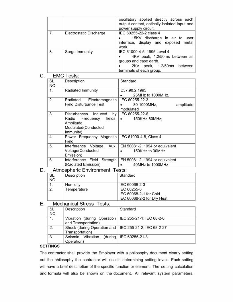
oscillatory applied directly across each output contact, optically isolated input and power supply circuit.
7. Electrostatic Discharge IEC 60255-22-2 class 4 • 15KV discharge in air to user interface, display and exposed metal work.
8. Surge Immunity IEC 61000-4-5: 1995 Level 4 • 4KV peak, 1.2/50ms between all groups and case earth. • 2KV peak, 1.2/50ms between terminals of each group.
C. EMC Tests: SL. NO
Description Standard
1. Radiated Immunity C37.90.2:1995 • 25MHz to 1000MHz,
2. Radiated Electromagnetic Field Disturbance Test
IEC 60255-22-3 • 80-1000MHz, amplitude modulated
3. Disturbances Induced by Radio Frequency fields, Amplitude Modulated(Conducted Immunity)
IEC 60255-22-6 • 150KHz-80MHz;
4. Power Frequency Magnetic Field
IEC 61000-4-8, Class 4
5. Interference Voltage, Aux. Voltage(Conducted Emission)
EN 50081-2, 1994 or equivalent • 150KHz to 30MHz
6. Interference Field Strength (Radiated Emission)
EN 50081-2, 1994 or equivalent • 40MHz to 1000MHz
D. Atmospheric Environment Tests: SL. NO
Description Standard
1. Humidity IEC 60068-2-3 2. Temperature IEC 60255-6
IEC 60068-2-1 for Cold IEC 60068-2-2 for Dry Heat
E. Mechanical Stress Tests: SL. NO
Description Standard
1. Vibration (during Operation and Transportation)
IEC 255-21-1; IEC 68-2-6
2. Shock (during Operation and Transportation)
IEC 255-21-2; IEC 68-2-27
3. Seismic Vibration (during Operation)
IEC 60255-21-3
SETTINGS
The contractor shall provide the Employer with a philosophy document clearly setting
out the philosophy the contractor will use in determining setting levels. Each setting
will have a brief description of the specific function or element. The setting calculation
and formula will also be shown on the document. All relevant system parameters,

line data, transformer data additionally used for calculating the setting will appear in the
setting document. The contractor will conduct system studies in determining fault
levels on different locations. These study results will also form part of the setting
document. Any additional information required to complete this exercise shall be
timely requested by the contractor.
The setting document will be presented and discussed with the Employer prior to final
issue of the document. The final accepted setting document should be made
available to the Employer in PDF format.
It is the contractor’s responsibility to configure each protection relay to provide the
protection and control facilities required. A full set of relay configuration and setting
files shall be included in the design and documentation submissions. The contractor
will issue three sets of setting documents once accepted by the client and consultant.
5.16 REQUIREMENTS OF AUXILIARY ITEMS ALUMINIUM TUBULAR CONDUCTOR
The aluminium tube shall be grade 63401 WP(range2) as per IS 5082.
There shall be no negative tolerance on OD and thickness of the tube. Other
tolerances shall be as per IS:2678 and 2673.
Tests: In accordance with stipulations of specification routine tests shall be
conducted on tubular conductor as per IS:5082. Also the wall thickness and ovality
shall be measured by ultrasonic method. In addition 0.2% proof tests on both parent
material and aluminium tube after welding shall be conducted.
Size 3" IPS (EH type),
Outer diameter 88.9 mm with no negative tolerance Thickness
of tube 7.62 mm with no negative tolerance
Cross-sectional area 1947 sq. mm.
Aluminium grade 63401 WP(range 2) conforming to IS:5082.
ACSR CONDUCTOR
Code and standard IS 398
Name MOOSE ACSR
Overall diameter 31.77 mm
Weight 2.004 kg/km
Ultimate tensile strength 161.2 kN minimum
Strands and wire diameter of
- Aluminium 54 / 3.53 mm
- Steel 7 / 3.53 mm
CLAMPS AND CONNECTORS
The material of clamps and connectors shall be Aluminium alloy casting conforming to
designation A6 of IS:617 for connecting to equipment terminals and conductors of
aluminium. In case the terminals are of copper, the same clamps/connectors shall be
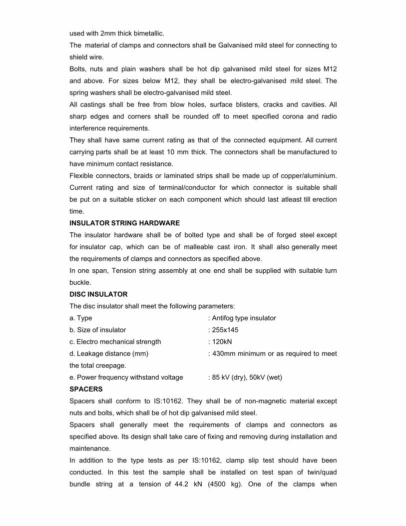
used with 2mm thick bimetallic.
The material of clamps and connectors shall be Galvanised mild steel for connecting to
shield wire.
Bolts, nuts and plain washers shall be hot dip galvanised mild steel for sizes M12
and above. For sizes below M12, they shall be electro-galvanised mild steel. The
spring washers shall be electro-galvanised mild steel.
All castings shall be free from blow holes, surface blisters, cracks and cavities. All
sharp edges and corners shall be rounded off to meet specified corona and radio
interference requirements.
They shall have same current rating as that of the connected equipment. All current
carrying parts shall be at least 10 mm thick. The connectors shall be manufactured to
have minimum contact resistance.
Flexible connectors, braids or laminated strips shall be made up of copper/aluminium.
Current rating and size of terminal/conductor for which connector is suitable shall
be put on a suitable sticker on each component which should last atleast till erection
time.
INSULATOR STRING HARDWARE
The insulator hardware shall be of bolted type and shall be of forged steel except
for insulator cap, which can be of malleable cast iron. It shall also generally meet
the requirements of clamps and connectors as specified above.
In one span, Tension string assembly at one end shall be supplied with suitable turn
buckle.
DISC INSULATOR
The disc insulator shall meet the following parameters:
a. Type : Antifog type insulator
b. Size of insulator : 255x145
c. Electro mechanical strength : 120kN
d. Leakage distance (mm) : 430mm minimum or as required to meet
the total creepage.
e. Power frequency withstand voltage : 85 kV (dry), 50kV (wet)
SPACERS
Spacers shall conform to IS:10162. They shall be of non-magnetic material except
nuts and bolts, which shall be of hot dip galvanised mild steel.
Spacers shall generally meet the requirements of clamps and connectors as
specified above. Its design shall take care of fixing and removing during installation and
maintenance.
In addition to the type tests as per IS:10162, clamp slip test should have been
conducted. In this test the sample shall be installed on test span of twin/quad
bundle string at a tension of 44.2 kN (4500 kg). One of the clamps when
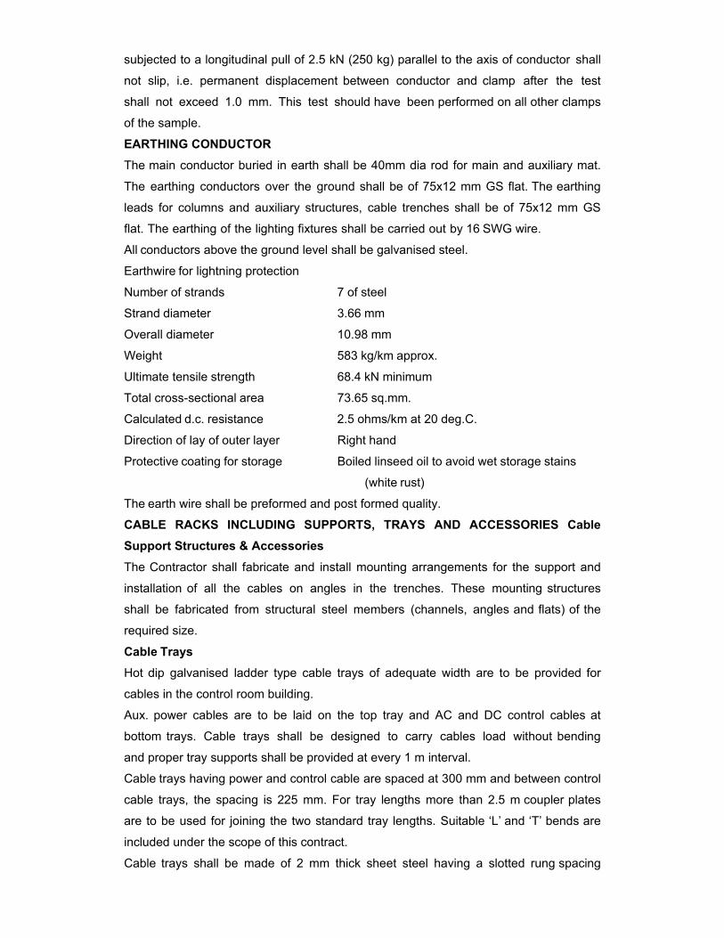
subjected to a longitudinal pull of 2.5 kN (250 kg) parallel to the axis of conductor shall
not slip, i.e. permanent displacement between conductor and clamp after the test
shall not exceed 1.0 mm. This test should have been performed on all other clamps
of the sample.
EARTHING CONDUCTOR
The main conductor buried in earth shall be 40mm dia rod for main and auxiliary mat.
The earthing conductors over the ground shall be of 75x12 mm GS flat. The earthing
leads for columns and auxiliary structures, cable trenches shall be of 75x12 mm GS
flat. The earthing of the lighting fixtures shall be carried out by 16 SWG wire.
All conductors above the ground level shall be galvanised steel.
Earthwire for lightning protection
Number of strands 7 of steel
Strand diameter 3.66 mm
Overall diameter 10.98 mm
Weight 583 kg/km approx.
Ultimate tensile strength 68.4 kN minimum
Total cross-sectional area 73.65 sq.mm.
Calculated d.c. resistance 2.5 ohms/km at 20 deg.C.
Direction of lay of outer layer Right hand
Protective coating for storage Boiled linseed oil to avoid wet storage stains
(white rust)
The earth wire shall be preformed and post formed quality.
CABLE RACKS INCLUDING SUPPORTS, TRAYS AND ACCESSORIES Cable Support Structures & Accessories
The Contractor shall fabricate and install mounting arrangements for the support and
installation of all the cables on angles in the trenches. These mounting structures
shall be fabricated from structural steel members (channels, angles and flats) of the
required size.
Cable Trays
Hot dip galvanised ladder type cable trays of adequate width are to be provided for
cables in the control room building.
Aux. power cables are to be laid on the top tray and AC and DC control cables at
bottom trays. Cable trays shall be designed to carry cables load without bending
and proper tray supports shall be provided at every 1 m interval.
Cable trays having power and control cable are spaced at 300 mm and between control
cable trays, the spacing is 225 mm. For tray lengths more than 2.5 m coupler plates
are to be used for joining the two standard tray lengths. Suitable ‘L’ and ‘T’ bends are
included under the scope of this contract.
Cable trays shall be made of 2 mm thick sheet steel having a slotted rung spacing

of 250 mm. Height of cable tray channel shall be 75 mm and the standard length
of trays shall be 2.5 m.
All nuts, bolts, washers etc. to be supplied by the Contractor shall be hot dip
galvanised after fabrication.
The Contractor shall perform all tests and inspection to ensure that material and
workmanship are according to the relevant standards.
BUSHINGS, HOLLOW COLUMN INSULATORS, SUPPORT INSULATORS, AND DISC INSULATORS
Bushings shall be manufactured and tested in accordance with IS:2099 & IEC:137
while hollow column insulators shall be manufactured and tested in accordance with
IEC 233/IS 5284. The support insulators shall be manufactured and tested as per
IS:2544 / IEC 168/IEC 273. The insulators shall also conform to IEC 815 as applicable.
Support insulators/ bushings/ hollow column insulators shall be designed to have
ample insulation, mechanical strength and rigidity for the conditions under which they
will be used.
Porcelain used shall be homogenous, free from laminations, cavities and other flaws
or imperfections that might affect the mechanical or dielectric quality and shall be
thoroughly vitrified, tough and impervious to moisture. Hollow porcelain should be in
one integral piece in green & fired stage.
Glazing of the porcelain shall be uniform brown in colour, free form blisters, burns
and other similar defects.
When operating at normal rated voltage there shall be no electric discharge
between conductor and insulators which would cause corrosion or injury to
conductors or when operating at normal rated voltage.
The design of the insulator shall be such that stresses due to expansion and
contraction in any part of the insulator shall be lead to deterioration. All ferrous parts
shall be hot dip galvanised.
Contractor shall make available data on all the essential features of design
including the method of assembly of shells and metal parts, number of shells per
insulator, the manner in which mechanical stresses are transmitted through shells to
adjacent parts, provision for meeting expansion stresses, results of corona and
thermal shock tests, recommended working strength and any special design or
arrangement employed to increase life under service conditions.
Post type insulators shall consist of a porcelain part permanently secured in metal
base to be mounted on supporting structures. They shall be capable of being
mounted upright. They shall be designed to withstand all shocks to which they may be
subjected to during operation of the associated equipment.
Bushing porcelain shall be robust and capable of withstanding the internal pressures
likely to occur in service. The design and location of clamps, the shape and the

strength of the porcelain flange securing the bushing to the tank shall be such that
there is no risk of fracture. All portions of the assembled porcelain enclosures and
supports other than gaskets, which may in any way be exposed to the atmosphere
shall be composed of completely non hygroscopic material such as metal or glazed
porcelain.
All iron parts shall be hot dip galvanised and all joints shall be air tight. Surface of
joints shall be trued, porcelain parts by grinding and metal parts by machining.
Insulator/ bushing design shall be such as to ensure a uniform compressive
pressure on the joints.
In accordance with the requirements stipulated under Chapter-G0, bushings, hollow
column insulators and support insulators shall conform to type tests and shall be
subjected to routine tests and acceptance test/ sample test in accordance with relevant
standards.
Insulator shall also meet requirement of IEC - 60815 as applicable, having
alternate long & short sheds.
CABINETS, BOXES, KIOSKS, PANELS, ETC. All types of control cabinets, junction boxes, marshaling boxes, lighting panels,
terminal boxes, operating mechanism boxes, etc. shall generally conform to IS:5039,
IS:8623 and IEC:439 as applicable.
They shall be of painted sheet steel or aluminium. The thickness of sheet steel shall
be 2mm cold rolled or 2.5mm hot rolled. The thickness of aluminium shall be 3mm
and shall provide rigidity. Top of the boxes shall be sloped towards rear of the box.
The paint shall be of grey RAL 9002 on the outside and glossy white inside. However,
the junction and switch boxes shall be of hot dip galvanised sheet steel of 1.6mm
thickness.
The cabinets/boxes/kiosks/panels shall be free standing or wall mounting or
pedestal mounting type. They shall have hinged doors with padlocking arrangement.
All doors, removable covers and plates shall be gasketed all around with neoprene
gaskets.
The degree of protection of all the outdoor boxes shall not be less than IP 55 as per IS
2147.
The cable entry shall be from bottom, for which removable gasketed cable gland plates
shall be provided.
Suitable 240V, single phase, 50Hz ac heaters with thermostats controlled by switch
and fuse shall be provided to maintain inside temperature 10deg. above the ambient.
The size of enclosure and the layout of equipment inside shall provide generous
clearances. Each cabinet/box/kiosk/panel shall be provided with a 15A, 240V ac, 2
pole, 3 pin industrial grade receptacle with switch. For incoming supply, MCB of
suitable rating shall be provided. Illumination of each compartment shall be with door

operated incandescent lamp. All control switches shall be of rotary switch type.
Each cabinet/box/kiosk/panel shall be provided with two earthing pads to receive
75mmx12mm GS flat. The connection shall be bolted type with two bolts per pad. The
hinged door shall be connected to body using flexible wire. The
cabinets/boxes/kiosks/panels shall also be provided with danger plate, and internal
wiring diagram pasted on inside of the door. The front label shall be on a 3mm thick
plastic plate with white letters engraved on black background.
BAY MARSHALLING BOX
Each bay of the switchyard shall be provided with a Bay Marshaling Box located at a
convenient location to receive and distribute cables within the bay. It shall meet all
the requirements as specified for cabinets/boxes above.
It shall have three separate distinct compartments for following purposes:
- To receive two incoming 415V, three phase, AC supplies controlled by 100A four pole
MCBs with auto changeover provision, and to distribute five (5) three phase ac supplies
controlled by 32A four pole MCBs. It shall also be provided with 63A, 3 phase 4 pin
industrial grade receptacle with rotary switch.
- To receive three phase incoming from first compartment and to distribute ten (10)
single phase ac supplies controlled by 16A two pole MCBs.
- 120 nos. terminal blocks in vertical formation for interlocking facility.
TERMINAL BLOCKS
They shall be non-disconnecting stud type of extensible design equivalent to Elmex
type CAT-M4. The terminal blocks shall be of 650V grade, and rated to continuously
carry maximum expected current. The conducting part shall be tinned or silver plated.
They shall be of moulded, non-inflammable thermosetting plastic. The material shall
not deteriorate with varied conditions of temperature and humidity. The terminal
blocks shall be fully enclosed with removable covers of transparent, non-deteriorating
plastic material. Insulating barriers shall be provided between the terminal blocks so
that the barriers do not hinder the wiring operation without removing the barriers.
The terminals shall be provided with marking tags for wiring identification.
Unless otherwise required (expected current rating) or specified, terminal blocks shall
be suitable for connecting the following conductors on each side:
• All CT & VT circuits - Min. four 2.5 sq.mm. copper flexible
conductor
• AC & DC power supply Circuits -Two 16 sq.mm. aluminium conductor
• Other control circuits - Min. two 2.5 sq.mm. copper flexible
conductor
The terminal blocks for CT and VT secondary leads shall be provided with test links
and isolating facilities. CT secondary leads shall also be provided with short
circuiting and earthing facilities.
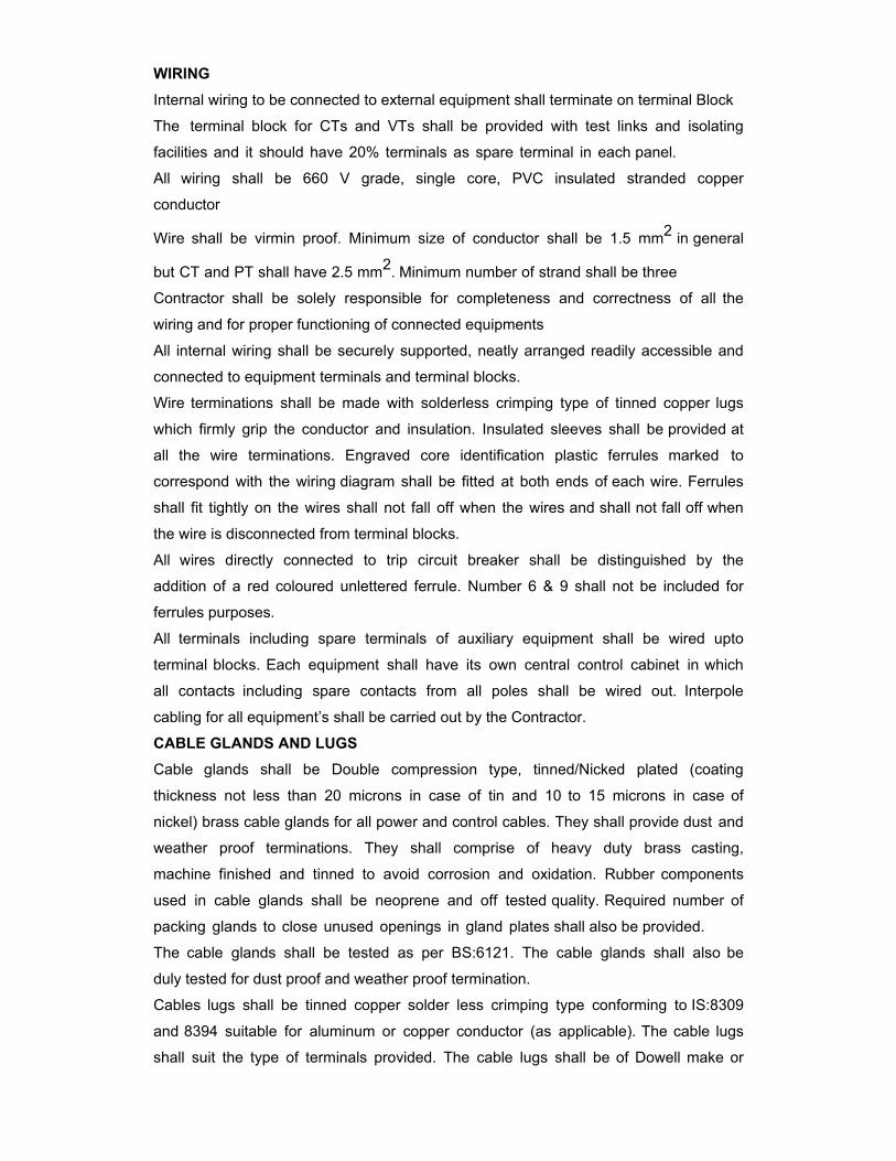
WIRING
Internal wiring to be connected to external equipment shall terminate on terminal Block
The terminal block for CTs and VTs shall be provided with test links and isolating
facilities and it should have 20% terminals as spare terminal in each panel.
All wiring shall be 660 V grade, single core, PVC insulated stranded copper
conductor
Wire shall be virmin proof. Minimum size of conductor shall be 1.5 mm2 in general
but CT and PT shall have 2.5 mm2. Minimum number of strand shall be three
Contractor shall be solely responsible for completeness and correctness of all the
wiring and for proper functioning of connected equipments
All internal wiring shall be securely supported, neatly arranged readily accessible and
connected to equipment terminals and terminal blocks.
Wire terminations shall be made with solderless crimping type of tinned copper lugs
which firmly grip the conductor and insulation. Insulated sleeves shall be provided at
all the wire terminations. Engraved core identification plastic ferrules marked to
correspond with the wiring diagram shall be fitted at both ends of each wire. Ferrules
shall fit tightly on the wires shall not fall off when the wires and shall not fall off when
the wire is disconnected from terminal blocks.
All wires directly connected to trip circuit breaker shall be distinguished by the
addition of a red coloured unlettered ferrule. Number 6 & 9 shall not be included for
ferrules purposes.
All terminals including spare terminals of auxiliary equipment shall be wired upto
terminal blocks. Each equipment shall have its own central control cabinet in which
all contacts including spare contacts from all poles shall be wired out. Interpole
cabling for all equipment’s shall be carried out by the Contractor.
CABLE GLANDS AND LUGS
Cable glands shall be Double compression type, tinned/Nicked plated (coating
thickness not less than 20 microns in case of tin and 10 to 15 microns in case of
nickel) brass cable glands for all power and control cables. They shall provide dust and
weather proof terminations. They shall comprise of heavy duty brass casting,
machine finished and tinned to avoid corrosion and oxidation. Rubber components
used in cable glands shall be neoprene and off tested quality. Required number of
packing glands to close unused openings in gland plates shall also be provided.
The cable glands shall be tested as per BS:6121. The cable glands shall also be
duly tested for dust proof and weather proof termination.
Cables lugs shall be tinned copper solder less crimping type conforming to IS:8309
and 8394 suitable for aluminum or copper conductor (as applicable). The cable lugs
shall suit the type of terminals provided. The cable lugs shall be of Dowell make or

equivalent.
CONDUITS, PIPES AND ACCESSORIES
The Contractor shall supply and install all rigid conduits, mild steel pipes, flexible
conduits, hume pipes, etc. including all necessary sundry materials, such as tees,
elbows, check nuts, bushing reduces, enlargers, wooden plugs, coupling caps,
nipples, gland sealing fittings, pull boxes, etc.
Rigid conduits shall be flow-coat metal conduits of Nagarjuna Coated Tubes or
equivalent make. The outer surface of the conduits shall be coated with hot-dip zinc
and chromate conversion coatings. The inner surface shall have silicone epoxy ester
coating for easy cable pulling. Mild steel pipes shall be hot-dip galvanised. All rigid
conduits/ pipes shall be of a reputed make.
Flexible conduits shall be heat-resistant lead coated steel, water-leak, fire and rust
proof, and be of PLICA make or equivalent.
MOTOR CONTROL CENTRE The 415 Volt motor control centres (if provided separately) shall conform to the
requirements for boxes/cabinets/kiosks. They shall be fixed type, shall be fully
sectionalised and shall be equipped with load break switches. Motor feeders shall
be provided with isolating switch fuse unit and Contractor with thermal overload relay
and single phase protection. The motor Contractor shall have one normally open
auxiliary contact for alarm purposes. The motor control circuit shall be independent
from all other control circuits.
Isolating Switches
The incoming power supply isolating switch operation handle shall be interlocked with
the control cabinet door as to prevent opening of door when main switch is closed.
Device for by passing the door interlock shall also be provided. Switch handle shall
have provision for locking in both fully open and fully closed positions.
Fuses
All fuses shall be of the HRC cartridge type, conforming to IS:2208 and suitable to
mount on plugin type of fuse bases. Fuses shall be provided with visible operation
indicators to show that they have operated. All accessible live connections shall be
adequately shrouded, and it shall be possible to change fuses with the circuit alive,
without danger of contact with live conductor. Insulated fuse pulling handle shall be
supplied with each control cabinet.
MOTORS (Ignore items which are not applicable to PV power plant) Motors shall be “Squirrel Cage” three phase induction motors of sufficient size
capable of satisfactory operation for the application and duty as required for the driven
equipment and shall conform to type tests and shall be subjected to routine tests as
per applicable standards.
Enclosures

For motors to be installed outdoor, the motor enclosure shall have degree of
protection IP:55. For motors to be installed indoor, i.e. inside a box, the motor
enclosure shall be dust proof equivalent to IP:44.
Two independent earthing points shall be provided on opposite sides of the motor
for bolted connection of earthing conductor.
Motors shall have drain plugs so located that they will drain water resulting
condensation or other causes from all pockets in the motor casing.
Motors weighing more than 25 kg shall be provided with eyebolts, lugs or other means
or facility for lifting.
Operational Features : Continuous motor ratings (name plate rating) shall be at least suitable for the driven
equipment at design duty operating point of driven equipment that will arise in
service.
Motors shall be capable of giving rated output without reduction in the expected life
span when operated continuously in the given system.
Starting Requirements
All induction motors shall be suitable for full voltage direct on-line starting. These
shall be capable of starting and accelerating to the rated speed alongwith the driven
equipment without exceeding the acceptable winding temperature even when the
supply voltage drops.
Motors shall be capable of withstanding the electrodynamic stresses and heating
imposed if it is started at a voltage of 110% of the rated value.
The locked rotor current shall not exceed six(6) times the rated full load current for all
motors subject to tolerance given in IS:325.
Motors when started with driven equipment imposing full staring torque and supply
voltage conditions specified shall be capable of withstanding at least two successive
starts from cold condition at room temperature and one start from hot condition
without injurious heating of winding. The motors shall also be suitable for three
equally spread starts per hour under the above referred supply condition.
The locked rotor withstand time under hot condition at 110% of rated voltage shall be
more than starting time with the driven equipment of minimum permissible voltage by a
least two seconds or 15% of the accelerating time whichever is greater. In case it is
not possible to meet the above requirement, the Contractor shall offer centrifugal
type speed switch mounted on the motor shaft which shall remain closed for speeds
lower than 20% and open for speeds above 20% of the rated. The speed switch
shall be capable of withstanding 120% of the rated speed in either directions of
rotation.
The maximum permissible temperature rise over the ambient temperature shall be
within the limits specified in IS:325 (for 3 phase induction motors) after adjustment
due to increased ambient temperature specified.
The double amplitude of motor vibration shall be within the limits specified in IS:729.
Vibration shall also be within the limits specified by the relevant standard for the driven
equipment when measured at the motor bearings.
All the induction motors shall be capable of running at 80% of rated voltage for a period
of 5 minutes.
AUXILIARY SWITCH
The auxiliary switch shall conform of following type tests:
Electrical endurance test - A minimum of 1000 operations for 2A. D.C. with a time
constant greater than or equal to 20 milliseconds with a subsequent examination of mV
drop/ visual defects/ temperature rise test.
Mechanical endurance test - A minimum of 5000 operations with a subsequent
checking of contact pressure test/ visual examination
- Heat run test on contacts
- IR/HV test, etc.
TYPE TEST
All equipment with their terminal connectors, control cabinets, main protective relays,
etc. as well as insulators, insulator strings with hardwares, clamps and connectors,
marshalling boxes, etc., shall conform to type tests and shall be subjected to routine
and acceptance tests in accordance with the requirements stipulated under respective
equipment sections.
6.0 TECHNICAL SPECIFICATION OF CIVIL WORK The solar plant shall be designed so as to conform with the latest engineering designs, architectural values and aesthetic features etc., in order to establish an ideal solar plant. 6.1 TOPOGRAPHICAL SURVEY – BHEL SCOPE Topographical survey of the proposed site shall be made available by BHEL. Further, BHEL, after careful study of the contour of the land has prepared a tentative PV array layout which could be used by the Contractor for designing the general layout with clear demarcation showing boundary pillars, location of control room, array yard, approach road, internal roads and general drainage etc. 6.2 SOIL TEST – BHEL SCOPE Soil test report of the proposed site shall be made available by BHEL. Contractor is required to consider the soil parameters of the proposed site as per the report vis-à-vis locations of control room, inverter rooms, substations & array yard to design suitable foundations for the respective structures. In addition to the above, available soil test report from customer (NTPC) is also provided to enable the vendor to have preliminary understanding of the soil parameters and thereby, cut down design and validation time for civil foundations. However, based on detailed soil investigation report from BHEL, optimization shall be done. Vendor shall ensure that the design of PV array foundations is suitable for rapid construction and smooth and fast erection and assembly of the module mounting structures within allotted time. Based on the soil test report, the contractor shall arrange for soil improvement wherever necessary. Contractor shall provide minimum three numbers bore-well after studying the availability of water-table at site. Supply and erection of necessary pumps, water-line and water tanks are also in the scope of the contractor. Contractor shall furnish calculations based on the head and discharge requirements of the pump rating and the water-line details. The water samples obtained shall be tested at NTPC/BHEL approved laboratory and reports shall be furnished. 6.3 PLANNING AND DESIGNING The contractor has to plan and design the pre-fab inverter room foundations each of approx. 30 sq m area or standard RCC framed structure as per similar dimensions with cable trench arrangement (subject to NTPC approval), plant building (CMCS) of RCC construction of minimum 250 sq. m area, HT panel foundation and CSS or conventional switchyard foundations as per the topographical survey and soil test reports. The contractor shall develop general layout drawing of plant array field, internal roads and pathways, drainage system, approach roads (ensuring no water logging in the plant premises) along with sanitary plumbing layout etc. All designs & drawings have to be developed based on specifications given in the tender, soil report and relevant IS unless otherwise specified. All details related to internal electrification, water supply and sewerage system should be clearly shown in the drawing. 6.4 INSTRUCTIONS TO CONTRACTOR 1. Optimization of land utilization with appropriate Array layout for maximum power packaging. For the PV array field, contractor shall furnish shadow factor analysis and shading diagram by employing applicable software and the details shall be incorporated in the PV array drawing.
2. Module cleaning system for periodic cleaning of modules with water points for every row, valves, hose pipes and nozzles as required. 3. All design should be done for optimal usage of space material, and labor without compromising the effect of shadow, cooling, ventilation, accessibility, losses during electrical connections etc. 4. The contractor shall submit preliminary drawings for approval and based on recommendations, in any, the contractor must submit final drawings for formal approval. Only approved drawings shall be used to proceed with construction works. 5. Buildings shall comply with National Building Code and/or other relevant international standards. OR Pre-Fab Inverter room (Numbers depending on the plant layout) with civil foundation and platform is also accepted subject to approval of BHEL/NTPC. Pre fab rooms designed shall take care of the Temperature within Inverter room under the conditions when ambient temperature is 50 deg C. Pre- Fab or Civil constructed Inverter room shall take into consideration HVAC details and the required ducting from each inverter shall be provided for proper extraction of Hot air from each Inverter so as to maintain the inverter temperature at its specified operating temperature. Based on HVAC calculations, If required contractor has to provide exhaust fans within each inverter room. The inverter room shall be complete in all respect viz (a). Trenches for DC and AC cables (3 tier arrangement with cable tray) and the required chequred plates to cover the open trenches within the inverter rooms. (b). Electrical wiring and light fittings with Fans. Light fittings shall be decided based on the Lux calculation to be furnished by the contractor and approved by BHEL/BHEL/NTPC. (c.) Fire alarm and Fire protection system in each inverter room shall be provided as per the IS. (d). Fire fighting equipment in each inverter room shall also be provided as per the IS. (e). Each Inverter room shall have the required space and furniture accessories to place the data communication system including operator chair, which is primarily (Such as PLC) which is primarily meant to collect the Inverters data, LT breaker data , HT switchboard data (Including Auxiliary and Numerical relays), Transformer data, String Monitoring system data, weather station data and any other data from the solar quadrant. Interfacing and Interconnecting to communication system within Inverter room to obtain the data mentioned as above shall be in the scope of contractor. (f). Signal cabling laying (paired screen cables, CAT 5 E Cables etc.) from each Inverter room to Control Monitoring and Control Station (CMCS) is in the scope of contractor. (g). Cable trench work and DC power cable laying in the PV array field to respective inverter rooms. (h). Interconnection of Inverter output cable to Transformer located in CSS via LT Breaker through cable trays. (i). 33 kV Cable laying and termination from HT side of the transformer to HT panel. (j). 33 kV Cable laying and termination from each HT panel located in respective CSS to common HT yard where the outgoing HT panel also located (Refer SLD attached). (k). 33 kV Cable laying in buried trench from outgoing HT panel to two pole structure. Supply, Erection and Cabling of 2 pole structure is in the scope of the contractor. (l). Supply and Laying of 33kV earthed cable from Two pole structure to Unchahar Thermal Power plant switch yard where BHEL supplied 220/33kV, 12.5 MVA Transformer is installed.

(m). Civil works of all the switchyard at Solar Power plant and 220/33 kV switchyard is in the scope of the contractor including supply and erection of gantry. (n). Design and construction of earth mat at Solar power plant and 220/33kV switchyard is ins the scope of the contractor. Design of earth mat for switchyard shall be got approved from BHEL/BHEL/NTPC before commencement of works. Complete switchyard engg layout shall be furnished from the approval. (o). Supply of Earthing material and earthing of solar array field (Supports structures, LA’s, Outdoor panels etc,), Swicthyard, LA’s, CSS components. Pre-Fab room, CSS enclosure, inverter room equipment and switchyard equipment is in the scope of contractor. 6. Land development including Levelling and Grading as per design formation level shall be done prior to commencement of any construction work. 7. The contractor shall submit complete drawings fulfilling all requirements for acceptance and approval by BHEL. Final design and drawings are to be prepared for construction as per instruction based on the approved drawings. 6.5 SITE DEVELOPMENT Before commencement of work including filling of the project site, the contractor must visit the site to assess the actual condition and situation of the land. Landscaping and leveling works on the entire area of the plant premises shall be done as per drawing developed by the contractor (and as per approval). All proper attention must be given to the drainage, water runoff and general slope of the plant area. 6.6 PLANT PERIPHERY FENCING (Not in the scope of this contract) The SPV Plant along with security cabin shall be fenced with combination of metallic chain link and barbed wire. The height of fencing shall be at least 2 m above the ground. M.S. angle posts shall confirm to “IS: 226-1969 and IS 800-1984”. Metallic chain link fencing shall be provided up-to 1.6 m above ground with pole spacing of 2.50 m between adjacent posts. The mesh size of chain link fencing shall be 50X50 mm of 8 gauge GI wire. The balance 0.4 m shall comprise of fencing of barbed wire on half Y steel post. The barb wire shall confirm to conforming to IS: 278. The spacing shall of barbed wires shall be maximum 12.5cm center to center. 6.7 PATHWAYS AND ROADS Pathways shall be leveled and compacted. Brick should be class II or better class (Fly-ash bricks produced by NTPC can also be employed provided it is readily available during the construction). The width of the internal pathways shall be 1.25 m minimum and shall be provided between each row. Peripheral pathways other than approach road shall be of 2.5m width and designed to facilitate movements to carry out daily maintenance. Approach road from nearest main road to control room shall be flexible type Bituminous of width at least 3.75 m with one meter shoulder each side as per IRC. 6.8 SECURITY CABIN Security cabin shall be of Pre-Fab type or RCC type subject to NTPC approval. Dimensions of security cabin shall be 3m x 3m. In addition to this, W/C shall be provided attached to the security cabin. All the necessary plumbing and sanitary lines shall be drawn. Necessary electrical connections for lighting and exhaust fan in W/C shall be provided. 6.9 CONTROL MONITORING AND CONTROL STATIONS (CMCS) For the operation & maintenance of SPV Plant the CMCS shall have a floor area of approximately 250 sq. m. It shall have 1. Air conditioned SCADA room 2. Store Room 3. Lobby

4. Pantry 5. Toilet and Urinal 6. Battery room Inverter room (approximately 30 sq. m) shall be pre-fab type or standard RCC framed structure of similar dimensions with cable trench arrangement and shall be located as per the indicative PV array layout as attached. The contractor shall submit the detailed drawing of CMCS and inverter rooms to BHEL for approval during the course of execution. The building shall be designed to meet national building code requirement. For enclosing the Air conditioned SCADA room, partition consisting of anodised aluminium extrusion and glazing (or Novopan board) shall be provided. 3 nos. 1.5 tonnes split AC units of approved make to be provided. GENERAL TECHNICAL SPECIFICATIONS: i) RCC Works All RCC works shall be of design mix as per IS 456-2000 and the materials used viz. Cement reinforcement, steel etc. shall be as per relevant IS standards. In addition IS: 2502 Code of Practice for Bending and Fixing of Bars for concrete Reinforcement must be complied. Reinforcement shall be high strength TMT Fe 415 or Fe 500 conforming to IS: 1786-1985. Concrete for all RCC works shall be machine mixed. For this purpose, contractor shall deploy mini batching plant having digitized recording system, which shall be calibrated with NABL/NPL traceable weights. The batching plant shall have the facility of obtaining the digitized output giving details of the various constituents (cement, aggregate, water, admixtures, fly ash etc.) in each batch of concrete being produced. Samples of concrete making materials and concrete shall be tested as per the provisions of technical specifications and field quality plan. ii) Masonry work All brick works shall be using at least II class bricks of approved quality as per IS 2212 and IS: 3495. The cement mortar for brick masonry shall be in the ratio 1 cement and 5 sand (by weight). The cement mortar shall be machine mixed. Bricks required for masonry work shall be thoroughly soaked in clean water tank for approximately two hours. Brick shall be laid in English bond style. Green masonry work shall be protected from rain. Masonry work shall be kept moist on all the faces for a period of seven days. iii) Doors & Windows: Doors, windows and ventilators of air-conditioned areas, entrance lobby of all buildings (where ever provided), and all windows and ventilators of main plant and service building shall have, electro colour dyed (anodised with 15 micron coating thickness) aluminium framework with glazing. Each window of SCADA Room should have venetian blinds. All doors of toilet areas shall be of steel framed solid core flush shutter. All other buildings doors windows ventilators (unless otherwise specified) shall be of steel. The doors frames shall be fabricated from 1.6 mm thick MS sheets and shall meet the general requirements of IS: 4351. Steel windows and ventilators shall be as per IS: 1361 and IS: 1038. All windows and ventilators on ground floor of all buildings shall be provided with suitable grill. Minimum size of door provided shall be 2.1 m high and 1.2 m wide. However for toilets minimum width shall be 0.75 m and office areas minimum width shall be 1.20m.
The main entrance shall include Mild Steel single leaf door. The structural steel shall conform to IS: 7452 and IS: 2062. The holdfasts shall be made from steel flats (50 mm and 5 mm thick). The fixtures, fastenings and door latch are to be made with same materials. All Windows shall be metal steel framed and manufactured from low carbon, hot-rolled Z-bar steel sections, and 25 mm wide and of minimum thickness 3 mm, drilled and tapped for hardware. The top of frames shall be provided with rain lip. Each window unit shall have a solid bronze polished, cam locking handle and strike. All steel windows shall be suitably painted after fabrication in accordance with the relevant Indian Standard(s). Fixing of metalled doors and windows shall be done in accordance to IS: 1081 and IS 7452. Doors and windows on external walls of the buildings (other than areas provided, with insulated metal claddings) shall be provided with RCC sunshade over the openings with 300 mm projection on either side of the openings. Projection of sunshade from the wall shall be minimum 450 mm over window openings and 750 mm over door openings except for main entrance door to the control room where the projection shall be 1500mm. iv) Glazing All accessible ventilators and windows of all buildings shall be provided with min. 4mm thick float glass, plain or tinted for preventing solar radiations, unless otherwise specified. For single glazed aluminium partitions and doors, float glass of 8mm or 10 mm thickness shall be used. All glazing work shall conform to IS:1083 and IS:3548. 6 mm reflective toughened glass, with following minimum technical characteristics: Solar factor 45% or less, U-value less than 5.7 W/SQMK, VLT min 35%: The glass to be used should be from the manufacturers of glass like Glavebel (Belgium), Saint Gobain (France) or Fort (USA) Or equivalent. The glass should be free from distortion and thermal stress. v) Plastering: All external surfaces shall have 18 mm cement plaster in two coats, under layer 12 mm thick cement plaster 1:5 and finished with a top layer 6 mm thick cement plaster 1:6 (DSR-2012 Item 13.11)with water proofing compound. White cement primer shall be used as per manufacturer’s recommendation. At least one coat of plaster shall be applied to interior walls by hand or mechanically, to a total thickness of 12 mm using 1:6, 1 cement and 6 sand. Plastering shall comply to IS: 1542, IS: 1661, IS:1630. Oil bound washable distemper on smooth surface applied with 2 mm thick Plaster of Paris putty for control room. Plaster of Paris (Gypsum Anhydrous) conforming to IS:2547 shall be used for plaster of Paris punning. vi) Flooring: The Cement shall be ordinary Portland cement as per IS:269. Flooring for all air conditioned areas, corridor and offices area shall be provided with vitrified ceramic tiles of size 600X 600 mm and min 9 mm thickness, laid with 3 mm ground joints as per approved pattern, painted nearly with 3X4 mm stainless epoxy grout or equivalent Flooring for stores, security cabin shall be of cement concrete flooring as per IS 2571-1970. Heavy duty (Grade V) dust pressed non-skid type ceramic tiles (300X 300 mm) as per IS 13755, shall be provided for flooring of toilets and pantries.

For pantry slab floor mirror polished (6 layers of polish) Granite stone (slab) of minimum thickness of 18 mm shall be used. vii) Roofing: Roof of the C.R. Building shall consist of Cast-in-situ RCC slab treated with a water proofing system which shall be an integral cement based treatment conforming to CPWD specification (item no. 25.8 of DSR 1997). The roof of the building shall be water proof with tarfelt 5 layer over screeding. The roof shall be designed for minimum superimposed load to 150 kg/m2. For efficient disposal of rainwater, the run off gradient for the roof shall not be less than 1:100 and the roof shall be provided with RCC water gutter, wherever required. Gutter shall be made water tight using suitable watertight treatment. This gradient can be provided either in structure or subsequently by screed concrete 1:2:4 (using 12.5 mm coarse aggregate) and/or cement mortar (1:4). However, minimum 25 mm thick cement mortar (1:4) shall be provided on top to achieve smooth surface. viii) Painting of Walls & Ceilings The paint shall be anti-fungal quality of reputed brand suitable for masonry surfaces for high rainfall zone. All painting on masonry or concrete surface shall preferably be applied by roller. If applied by brush then same shall be finished off with roller. For painting on concrete, masonry and plastered surface IS:2395 shall be followed. All paints shall be of approved make including chemical resistant paint. Minimum 2 finishing coats of paint shall be applied over a coat of primer. For painting on steel work and ferrous metals, BS: 5493 and IS:1477 shall be followed. The type of surface preparation, thickness and type of primer, intermediate and finishing paint shall be according to the painting system adopted. The cement paint as per as per IS : 5410 shall be of approved brand and manufacturer. Ceiling of all rooms except Battery room shall be white washed. The ceiling of Battery room (if provided) shall be acid resistant paint. ix) Plinth Protection Plinth protection shall be provided around all the buildings with Brickbats and PCC 1:2:4 & smoothly finish of top surface. x) Water supply GI pipes of Medium quality conforming to IS 1239 (Part I-1990) and IS 1795-1982 (reaffirmed 1990) for Mild Steel pipes shall be used for all water supply and plumbing works. The Sintex or equivalent make PVC storage water storage tank conforming to IS:12701 shall be provided over the roof of the control room with adequate capacity for 12 No person and 24 hr requirement, complete with all fitting including float valve, stop cock etc. The capacity of the tank shall be minimum 500 litres. As explained earlier, Contractor shall provide minimum three numbers bore-well after studying the availability of water-table at site. Supply and erection of necessary pumps, water-line and water tanks are also in the scope of the contractor. Required water connection to service the CMCS shall be in the scope of the contractor. Contractor shall furnish calculations based on the head and discharge requirements of the pump rating and the water-line details. The water samples obtained shall be tested at NTPC/BHEL approved laboratory and reports shall be furnished. xi) Plumbing and Sanitary Each toilet shall have the following minimum fittings. (a) WC (Western type) 390 mm high with toilet paper roll holder and all fittings and WC (Indian Type) with all fittings (both types of WCs shall be provided at alternate locations).

(b) Urinal (430 x 260 x 350 mm size) with all fittings. (c) Wash basin (550 x 400 mm) with all fittings. (d) Bathroom mirror (600 x 450 x 6 mm thick) hard board backing (e) CP brass towel rail (600 x 20 mm) with C.P. brass brackets (f) Soap holder and liquid soap dispenser All fittings, fastener, grating shall be chromium plated. Necessary plumbing lines shall be provided for office cum control room building and Security cabin. The floor finish for washroom, pantry and toilet shall be vitrified ceramic anti-slip tiles and Dado glaze ceramic tiles upto 2.1m shall be used. The normal size of Ceramic tiles shall be 300 mm X 300 mm X 9 mm and shall comply IS: 15622. The contractor shall design & provide below ground one septic tank and two soak pits and assuming that a total of 12 No. persons shall be working for O&M in combined three shifts. The pantry shall consist of one number stainless steel pantry sink, as per IS : 13983, of size 610 x 510 mm, bowl depth 200 mm with drain board of at least 450 mm length with trap, with inlet and outlet connections and GI concealed water supply pipe of minimum 12 mm dia. of medium class, sanitary pipe of minimum 75 mm diameter, floor trap with Stainless Steel grating, inlet and outlet connections for supply and drainage, with all bends, tees, junctions, sockets, etc., as are necessary for the commissioning and efficient functioning of the pantry (all sanitary fittings shall be heavy duty chrome plated brass, unless noted otherwise). xii) Electrification of Building Electrification of building shall be carried out as per IS 732-1989, IS 4648 1968 and other relevant standards. xiii) Stairs: Contractor to provide service ladder made up of aluminium with load bearing capacity of at least 150 kg to access the roof for maintenance of communication equipment and water tank. xiv) False Ceiling: The control room shall be provided with false ceiling of 15 mm thick mineral fibre board, in tile form of size 600mm x 600mm, along with galvanised light gauge rolled form supporting system in double web construction pre painted with steel capping, of approved shade and colour, to give grid of maximum size of 1200x600 mm as per manufacturers details including supporting grid system, expansion fasteners for suspension arrangement from RCC, providing openings for AC ducts(if required), return air grills(if required), light fixtures, etc., all complete. xv) Lighting The lighting design of the buildings shall be carried out as per IS 3646-1992. The average illumination level of control room shall be 300 Lux with Mirror optics with anti-glare type or Decorative Mirror optics type of fixture. The building shall be provided with adequate light fittings, 5A/ 15A 1 phase sockets, fans etc. controlled by required ratings of MCBs and MCB DBs. All MCBs / Isolators shall be mounted inside the panel and a bakelite/fibre glass sheet shall be provided inside such that operating knobs project out of it for safe operation against accidental contact. Operating handle of incoming MCCB/isolator shall project out of door. Wiring inside the panel shall be carried out with 1100V grade PVC insulated stranded copper conductors of adequate size. Supply and providing of suitable illumination along the peripheral roads, control room, inverter rooms and other facilities like switch-yards and outside CSS etc. inside the plant shall be done. 6.9 FENCING OF 33 kV SWITCHYARD
The fencing work required for electrical switchyard shall be of barbed wire / twisted G.I. fencing wire in accordance to IS: 278 and CEIG requirement. It shall be of commercial type and conforming to “IS: 226-1969”. M.S. angle posts shall confirm to “IS: 226-1969 and IS 800-1984. Gate of minimum 3m width shall be provided. 6.10 WATER WASHING ARRANGEMENT FOR MODULE CLEANING Contractor shall provide permanent arrangement for module washing in the SPV Plant. This shall include installing tube well with pump and motor and laying network of GI pipe in each row of SPV panels. Opening from the GI pipe with manual isolating valves with nozzles should be provided at regular interval in each row of SPV panels. Contractor shall provide the single line diagram of water washing arrangement with location of pump to BHEL for approval. Contractor shall make arrangement for water storage in the form of underground sumps or over-head tanks as required for module washing system as well as fire fighting facility. 6.11 DRAINAGE SYSTEM Suitable water drainage system for rainy & storm water and cross drainages shall be designed and constructed after approval of respective drawings. Brick or stone masonry shall be acceptable. Drainage philosophy based on site area levels and invert levels of drains shall be developed and document/drawings shall be submitted. 6.12 SPECIFICATION OF INVERTER ROOM Inverters shall be housed in Pre-fab inverter rooms or standard RCC framed structures of same dimensions with cable trench arrangement located in the PV array field (The use of pre-fab inverter rooms is subject to approval by NTPC). The building shall be constructed as per National Building Code. The foundation platform for the pre-fab structure shall be constructed with RCC and masonry works as per required dimensions. The Floor Finish Level of the inverter room shall be min. 450mm above surrounding Ground Level. Cable trenches with GI cable trays shall be provided. Bottom of the trench shall be minimum 100mm above surrounding ground level. Cladding system should be a weather tight building envelope, suitable for complete life of solar plant. The layout of Inverter room shall be designed so as to divert the heat generated from each inverter outside the room. The inverter room shall be designed for a life of 25 years. The successful contractor shall have to get the structural design done as per the prevailing IS codes. The structural design of inverter room of each identical type shall have to be proof checked by any IIT / NIT. The structure design shall have to be got approved from BHEL/NTPC, before actual start of the work. i. Structure: The steel structure of the Shelter shall be designed for loads and load combination as per Indian Standards (latest revisions) such as IS: 875, IS:1893, IS:800, IS:456 etc The steel shall be hot-dipped galvanized with a minimum Z180 coating for load bearing applications and Z120 for non-load bearing applications. Alternately, the steel hot-dipped in Alum/Zinc (with 55% Aluminium and 45% Zinc) can be also used. The applicable codes are ASTM A653 for galvanized and ASTM A792 for Galvalume/Zincalume. ii. Fasteners:

Steel bolts, nuts and washers complying with AS 1112:2000. Self-drilling screws complying with AS 3566.1 and AS 3566.2 shall be used. iii. Roof: The roofing shall be double skin trapezoidal profile sheet of pre-painted 0.45 mm BMT (Base Metal Thickness) Hi Tensile Zincalume/Galvalume 0.5 TCT, confirming to IS:513 and ASTM A792M/AS1397. Stiffening ribs / subtle fluting for effective water shedding and special male/ female ends with full return legs on side laps for purlin support and anti-capillary flute in side lap shall be provided. Both upper and lower sheets shall be separated through spacers and fastened through zinc /zinc-tin coated self-drilling screws. The fastener size shall be calculated as per the design or manufacturers recommendations. Both sheets shall be sandwiched with an under insulation of 50mm thick glass wool of density 50 kg/m3 with aluminum foil backing and complete with gutters and down take pipes. Along with Flashing & Top cap of required size and color complete with all necessary hardware complete. Roof shall be projected at least 600 mm from the wall. iv. Doors Frames Door frames shall be of T-iron frame of mild steel Tee-sections as per DSR- 2007 item no 10.13. All doors shall be provided necessary fittings like hinges, handles, mortice locks, tower bolts, stopper, hydraulic door closer, magic eye (for main doors) etc of CP brass complete as detailed in tender drawing or submitted by contractor in shop drawing and approved by BHEL. Black powder coated aluminium doors shall be with extruded built up standard tubular sections, appropriate Z sections and other sections of approved make conforming to IS: 733 and IS:1285, fixed to Pre-engineered structure including necessary filling up of gaps at junctions with required PVC/neoprene felt etc. including hinges / pivots and double action hydraulic floor spring of approved brand and manufacture IS:6315 marked, lock, handle and all necessary fittings. The door entrance shall include Mild Steel single leaf door. The structural steel shall conform to IS: 7452 and IS: 2062. The holdfasts shall be made from steel flats (50 mm and 5 mm thick). The fixtures, fastenings and door latch are to be made with same materials. v. Windows Frame: Aluminium black powder coated section, frame shall be of 92x31 mm, minimum 16G thick as per approved design vi. Ventilators Aluminum black powder coated frame of minimum size 62x25 mm and 16G thick as per approved design. Suitable sunshades made out of approved colour sheet reinforced with Aluminium angle frame of minimum 35x35x4 mm size with soffit of same material will be provided to all external windows and door. The minimum projection for the sunshades will be 450 mm and 300mm wider than the width of the opening vii. Plinth Protection: 750 wide plinth protection 50 mm thick of cement concrete 1:3:6 (1cement : 3 coarse sand : 6 graded stone aggregate 20 mm nominal size) over 75 mm bed of dry brick ballast 40 mm nominal size well rammed and consolidated and grouted with fine sand including finishing the top smooth, shall be provided around the Pre-Engineered Structure. viii. Floor Finish Flooring, including preparation of surface, cleaning etc shall be of cement concrete flooring as per IS 2571-1970 with ironite hardener. The inverter room floor shall be at least 450 mm above the ground level.
IX. Wall Cladding: The walls shall be of double skinned trapezoidal profile sheet of pre-painted 0.45 mm BMT (Base Metal Thickness) Hi Tensile Zincalume/Galvalume 0.5 TCT, confirming to IS:513 and ASTM A792M/AS1397. The profile shall be trapezoidal. Both the walls should be separated by spacers system made up of cold formed steel bars and fastened through zinc /zinc-tin coated self-drilling screws. X. Wall Insulation: All voids of external and internal metalled walls shall be filled with 50 mm thick Mineral glass Wool/rockwool insulation of density 50 kg/m3 covered with high strength meshless Aluminium foil with proper supports etc as approved. XI. Painting The exterior sheet (roof as well as wall) shall have total paint thickness of 25 micrometre comprising of 20 micrometre exterior coat of Super Durable Polyester (XRW) and 5 micrometer primers coats. Other faces of sheets shall be painted with 10 micron polyester over 5 micrometre primer coats. The colour shade shall be subject to BHEL-BHEL/NTPC approval XII. Lighting: The inverter room shall be provided with electric light to achieve average illumination level of 75 Lux. However room should be designed to utilised maximum natural light during the day.

7.0 GENERAL REQUIREMENTS
7.1 SUBMISSION OF ENGINEERING DATA & DRAWINGS
The contractor shall submit the following Engineering drawings, data, design and
engineering information (not limited to the list given below) in both soft copy (CD) and
hard copy to NTPC and BHEL along with a “Master Drawing List (MDL)”. Along with the
LOA/PO, BHEL shall furnish the MDL along with the schedule for each drawing to the
successful bidder. Contractor shall ensure compliance to this schedule.
1. SPV array and cable layout.
2. Module foundation
3. Main & service road with general drainage
4. Inverter room layout, CSS/conventional switchyards and CMCS building layout
5. 33 kV Switchyard
6. Power Evacuation system
7. 33/220 kV Transformer and related switchgear equipment.
8. Earthing
9. Constructional details (Civil and Structural drawings) for Inverter room,
CSS/conventional switchyards, CMCS building, 220 kV Transformer foundation
and the like.
Any other Engineering drawings, data, design and engineering information (whether
specifically mentioned in the document or not) require to fulfill the stated scope of
work shall be deemed to be included.
7.2 Auxiliary Power Requirement Arrangement of auxiliary power supply during construction and O&M period shall be
in the scope of the contractor. Contractor shall install compatible inverter and/or
transformer for auxiliary power requirements of lighting, water pump(s), Electronics
equipment, switchgear panels etc. In addition to above, contractor must also provide
DC battery bank for functional requirement of breaker, SCADA and emergency
lighting of CMCS. VRLA battery shall not be accepted. Tubular LMLA Battery is
accepted.
7.3 Mandatory Spares & Consumables
Mandatory spares at tached as per annexure are those which are considered
essential. Vendor shall furnish the itemized and total price for spares. All
mandatory spares shall be delivered at site.
Contractor shall maintain the mandatory spares, consumables & various components of
SPV plant for smooth running during O&M period. Contractor shall also replenish the
consumed mandatory spares during the O&M period to maintain the stock as
mentioned in Bid Proposal Sheet. The contractor shall also mention the source of
supply.
7.4 Fire protection & Fire fighting system
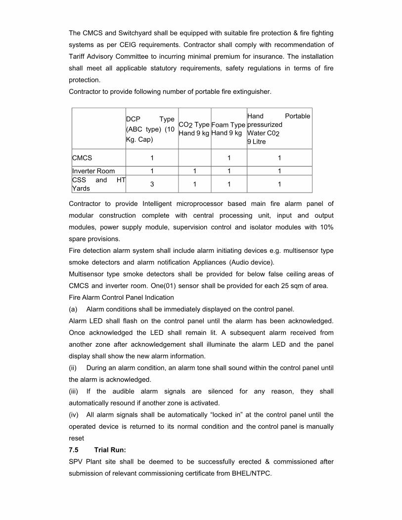
The CMCS and Switchyard shall be equipped with suitable fire protection & fire fighting
systems as per CEIG requirements. Contractor shall comply with recommendation of
Tariff Advisory Committee to incurring minimal premium for insurance. The installation
shall meet all applicable statutory requirements, safety regulations in terms of fire
protection.
Contractor to provide following number of portable fire extinguisher.
DCP Type (ABC type) (10 Kg. Cap)
CO2 TypeHand 9 kg
Foam TypeHand 9 kg
Hand Portable pressurized Water C02 9 Litre
CMCS 1 1 1
Inverter Room 1 1 1 1 CSS and HT Yards 3 1 1 1
Contractor to provide Intelligent microprocessor based main fire alarm panel of
modular construction complete with central processing unit, input and output
modules, power supply module, supervision control and isolator modules with 10%
spare provisions.
Fire detection alarm system shall include alarm initiating devices e.g. multisensor type
smoke detectors and alarm notification Appliances (Audio device).
Multisensor type smoke detectors shall be provided for below false ceiling areas of
CMCS and inverter room. One(01) sensor shall be provided for each 25 sqm of area.
Fire Alarm Control Panel Indication
(a) Alarm conditions shall be immediately displayed on the control panel.
Alarm LED shall flash on the control panel until the alarm has been acknowledged.
Once acknowledged the LED shall remain lit. A subsequent alarm received from
another zone after acknowledgement shall illuminate the alarm LED and the panel
display shall show the new alarm information.
(ii) During an alarm condition, an alarm tone shall sound within the control panel until
the alarm is acknowledged.
(iii) If the audible alarm signals are silenced for any reason, they shall
automatically resound if another zone is activated.
(iv) All alarm signals shall be automatically “locked in” at the control panel until the
operated device is returned to its normal condition and the control panel is manually
reset
7.5 Trial Run: SPV Plant site shall be deemed to be successfully erected & commissioned after
submission of relevant commissioning certificate from BHEL/NTPC.
During the trial operation, SPV plant shall perform trouble-free operation for
cumulative 72 hours during which functionality of all plant components shall be
demonstrated and the system shall be in Generating mode.
7.6 Warranty: The successful contractor shall provide a warranty covering all including mechanical
structure, electrical works including PCU/inverters/maximum power point tracker
unit/distribution boards/digital meters/switchgear and overall workmanship of the
solar power plants/system against any manufacturing/design/installation defects for a
period of five (5) years.
The warranty period shall commence from the date of successful completion of trial
run as per clause No 7.5
7.7 TAKING OVER: Upon successful completion of all the facilities pertaining to the scope of work, contractor shall approach the owner in writing for “final take over” of the plant. On
receipt of such request, owner shall issue to the contractor a taking over certificate
as a proof of the final acceptance of the system. Such certificate shall not relieve
the Contractor of any of his obligations which otherwise survive, by the terms and
conditions of the Contract after issuance of such certificate.
7.8 INSURANCE: Contractor shall organize insurance for all the materials supplied by him. The insurance
shall be arranged for the materials supplied by the successful bidder for
a) The goods in transit
b) Storage, erection and commissioning
8.0 SPECIFICATION FOR OPERATION AND MAINTENANCE CONTRACT
The successful contractor shall provide Operation and maintenance of SPV Plant for a
period of one year from date of completion of trial run. During O&M period,
BHEL/NTPC personnel shall have unrestricted entry to the Solar plant and Control
Room any time. BHEL/NTPC may suitable depute its personals to associate with O&M
activities. Contractor shall assist them in developing expertise through their day to day
O&M activities. All records of maintenance must be maintained by the contractor
which can be accessed by BHEL/NTPC on demand. These readings are to be
handed over to BHEL/NTPC after the O&M period of contract.
After O&M period, BHEL/NTPC may at its discretion decide to extend the existing
O&M contract on mutually acceptable terms & conditions or undertake the O&M of
the SPV Plant on its own.
The contractor shall be responsible for supply of all spare parts, repairs / replacement
of any defective equipment(s) at his own cost as required from time to time during
the O&M period.
The contractor shall be responsible for all the required activities for the successful
running, optimum energy generation etc.
(a) Deputation of O&M, engineering and supporting personal.
(b) Ensure, successful running of SPV Plant for optimum energy generation.
(c) Safety and protect ion of the plant by deputing sufficient security personals
(d) Monitoring, controlling, troubleshooting, maintaining of records, registers.
(e) Supply of all spares, consumables and fixing / application of the same.
(f) Cleaning of the plant including array yard on regular basis and as and when
required.
(g) Normal and preventive maintenance of the plant such as cleaning of module
surface, tightening of all electrical connections, line accessories, transformers and
associated switchgear on the HT side.
(h) Conducting periodical checking, testing, over hauling and preventive action.
(i) Submission of periodical reports to the owner on the energy generation & operating
conditions of the SPV plant.
(j) BHEL/NTPC shall take only Fire & Allied Peril insurance during O&M period. All
other type of insurance during O&M period shall be taken by the contractor.
(k) Daily work of the operators involves logging the voltage, current, power factor,
power and energy output of the SPV plant, temperature, logging down individual array
output data once a day
(l) The operator shall record monthly energy output of each array and transformer
and reports shall be prepared on performance of SPV plant.
(g) The contractor shall at his own expense provide all amenities to his workmen as
per applicable laws and rules.

(m) The Contractor shall ensure that all safety measures are taken at the site to
avoid accidents to his employees or his Co-contractor’s employees
(n) The Contractor shall immediately report the accidents, if any, to the Engineer In
charge & to all the concerned authorities as per prevailing laws of the state.
(o) The Contractor shall comply with the provision of all relevant Acts of Central or
State Governments including payment of Wages Act 1936, Minimum Wages Act
1948, Employer's Liability Act 1938, Workmen's Compensation Act 1923, Industrial
Dispute Act 1947, Maturity Benefit Act 1961, Employees State Insurance Act 1948,
Contract Labor (Regulations & Abolishment) Act 1970 or any modification thereof or
any other law relating whereto and rules made there under from time to time.
(p) In order to ensure longevity, safety of the core equipment and optimum performance
of the system the contractor should use only genuine spares of high quality
standards.
9.0 PERFORMANCE GUARANTEE (PG) TEST This test shall be binding on both the parties of the Contract to determine compliance of
the equipment with the functional guarantee (Excluding PV modules- BHEL supply).
Any special equipment, instrumentation tools and tackles required for the
successful completion of the Performance Guarantee Test shall be provided by the
Contractor free of cost. The accuracy class of the instrumentation shall be as per the
relevant clause of documents. The procedure for PG demonstration test shall be as
follow:
1. A calibrated pyranometer shall be installed by the Contractor at the location mutually agreed by Contractor and BHEL/NTPC. The test report for the calibration shall be submitted by the Contractor for approval by BHEL/NTPC. The output of this pyranometer for three months of the PG test shall be made available at SCADA. 2. Actual energy exported from the plant supplied by the Contractor shall be noted for three consecutive months. For this purpose, the net energy exported at the HV side of 33/220 kV transformer shall be taken into account. 3. This measured value of energy at step-2 shall be compared with “Base Generation” for the PG test – 14.645 Million units at 220 kV level. 4. “Base Generation” for a month is the quoted generation by BHEL to NTPC (14.645 MU). BHEL shall furnish the detailed procedure of PG test during detailed engineering to the successful bidder. Following factors shall be considered for computing the “Base Generation” a) Effect due to variation of meteorological parameters e.g. ambient temperature, wind speed, humidity etc shall not be considered. b) Generation loss due to grid outage( or power evacuation system which is not in the scope of the Contractor): The measured global solar radiation of the period of the outage of the power evacuation system shall be excluded to calculate average global solar radiation for the period of PG test. In order to facilitate this SCADA shall log the Grid loss hours and corresponding solar energy (Wh) for computation of energy generation lost due to Grid loss hours. It is essential that the SCADA software must have built-in algorithm to convert solar radiation obtained from pyranometer in Watt/m2 to WattHour. Note: Contractor shall coordinate with BHEL team at site during PG test to conduct the complete procedure.

10.0 QUALITY ASSURANCE AND INSPECTION FOR CIVIL WORKS Contractor shall furnish the MQPs of various BOS items and shall demonstrate as per the MQP during inspection at the respective works. Each MQP shall be submitted for approval by BHEL/NTPC. BHEL, in association with the contractor, shall get MQPs cleared. Following QA chapter are attached.
a. 33KV Switchyard equipments
b. Cabling and earthing, Lightning Protection
c. Pyranometer, Anemometer, Thermometers
d. LT Switchgear
e. LT Bus Duct
f. Power Conditioning unit
g. SCADA
h. Power Transformers
i. LT Control cable
j. LT Power cable
k. HT cables
l. Civil work
a. 33 kV Switchyard Equipments Attributes /
Characteristics Items/Components Sub Systems
Make, model, Type & Rating, Test Certificate
Routine &
Acceptance Test as per IS /
IEC
Functional requirement s as per NTPC Specificatio n
Circuit Breaker (IEC:62271-100) Y Y Y
Interruptor & hollow insulator (IEC:233/ IS:5284) Y Y
Y Isolator (IEC:62271-102) Y Y Y Current Transformer (IEC:60044) Y Y Y Voltage Tramsformer (IEC:) Y Y
Y Bus Post Insualtor (IEC:168 / 273 / IS:2544) Y Y
Y Disc,Pin & String Insualtor (IEC:383 / IS:731) Y Y
Y Surge Arrestor (IEC:99-4) Y Y Y Hardware fittings for Insulator (IS:2486 / BS:3288) Y Y
Y Spacer Clamps & Connector (IS:10162 / 5561) Y Y
Y Aluminium Tube (IS:5082 / 2673 / 2678) Y Y
Y Conductor (IS:398) Y Y Y Galvanised Steel Structures (IS:2062/2629/4759/6745) Y Y
Y Vibration Damper (IS:9708) Y Y Y Sag Compensating Spring DIN:2089/2096 IS:3195 / 7906 Y Y
Y Control & Relay Panel Y Y Y Leakage Current Analyser Y Y Y Protection Relays Y Y Y Tariff Metering System as per IEC 62052-11 & 62053-22 & IS 14697) Y
Y Y
Synchronising Trolly Y Y Y Relay Test Kit Y Y Y Surge Monitor Y Y Y
Notes : 1) This is an indicative list of test/checks. The manufacture is to furnish a
detailed Quality Plan indicating the practice and procedure along with relevant supporting documents during QP finalisation for all items.
2) All major Bought Out Items will be subject to NTPC approval.
b. CABLING, EARTHING, LIGHTNING PROTECTION
ATTRIBUTES / CHARACTERISTICS
ITEMS/COMPONENTS / SUB SYSTEMS
Dim
ensi
on
Pai
nt s
hade
, pai
nt th
ickn
ess,
adh
esio
n
Pre
-trea
tmen
t of s
heet
IP p
rote
ctio
n
Pro
of lo
ad*
Sur
face
fini
sh
Def
lect
ion
test
*
HV
& IR
Gal
vani
se T
est (
If A
pplic
able
)
Func
tiona
l
Bou
ght o
ut it
ems/
Bill
of m
ater
ial
Rou
tine
test
s as
per
rel
evan
t sta
ndar
d &
sp
ecifi
catio
n
Acc
epta
nce
test
s as
per
rele
vant
sta
ndar
d &
spec
ifica
tion
Con
stru
ctio
nal f
eatu
re a
s pe
r NTP
C
Sifi
ti
Wall Mounted-Lighting Panel (IS-513, IS:5, IS:2629, 2633, 6745)
Y Y Y Y Y Y Y Y Y Y Y Y
Switch box/junction box/ Receptacles Panel (IS-513, IS:5, IS:2629,
Y Y Y Y Y Y Y Y Y Y Y Y
Cable glands(BS-6121) Y Y Cable lug(IS-8309) Y Y Lighting wire(IS-694) Y Y Flexible conduits Y Y YConduits(Galvanise & Epoxy) IS-9537 & IS-
Y Y Y Y Y
RCC Hume Pipe (IS-458) Y Cable termination & straight through joint (VDE-0278)
Y Y Y
Cable Trays, Flexible supports system & accessories IS-
Y Y Y Y Y Y Y Y Y Y Y
Trefoil clamp Y YGI flats for earthing & lighting protection (IS 2062, 2629,
Y Y Y Y Y
GI wire (IS-280) Y Y Fire Sealing System ( BS – 476)
Y Y Y
Note: 1.This is an indicative list of tests /checks. The manufacturer is to furnish a detailed Quality Plan indicating the practice and procedure along with relevant supporting documents. 2.* Deflection Test on cable trays and Proof Load test on cable trays support system will be as per details given in the NTPC technical specification & approved MQP. The above acceptance tests shall be done only on one sample from each size of offered lot.

c. Pyannometer, anemometer, thermometers:
Routine test reports as per relevant standard
Calibration tests reports as per standard
Test report (TR): Should be supplied with the unit after all tests. The TR shall include detailed description of all parameters tested qualified and warranted.
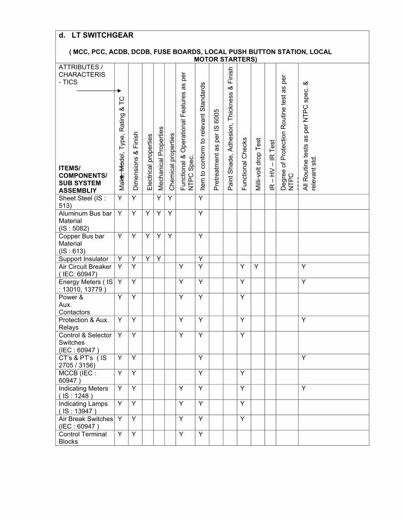
d. LT SWITCHGEAR
( MCC, PCC, ACDB, DCDB, FUSE BOARDS, LOCAL PUSH BUTTON STATION, LOCAL MOTOR STARTERS)
ATTRIBUTES / CHARACTERIS- TICS
ITEMS/ COMPONENTS/ SUB SYSTEM ASSEMBLIY
Mak
e, M
odel
, Typ
e, R
atin
g &
TC
Dim
ensi
ons
& F
inis
h
Ele
ctric
al p
rope
rties
Mec
hani
cal P
rope
rties
Che
mic
al p
rope
rties
Func
tiona
l & O
pera
tiona
l Fea
ture
s as
per
N
TPC
Spe
c.
Item
to c
onfo
rm to
rele
vant
Sta
ndar
ds
Pre
treat
men
t as
per I
S 6
005
Pain
t Sha
de, A
dhes
ion,
Thi
ckne
ss &
Fin
ish
Func
tiona
l Che
cks
Milli
-vol
t dro
p Te
st
IR –
HV
– IR
Tes
t
Deg
ree
of P
rote
ctio
n R
outin
e te
st a
s pe
r N
TPC
sp
ec
All
Rou
tine
test
s as
per
NTP
C s
pec.
&
rele
vant
std
.
Sheet Steel (IS : 513)
Y Y Y Y Y
Aluminum Bus bar Material (IS : 5082)
Y Y Y Y Y Y
Copper Bus bar Material (IS : 613)
Y Y Y Y Y Y
Support Insulator Y Y Y Y Y Air Circuit Breaker ( IEC: 60947)
Y Y Y Y Y Y Y
Energy Meters ( IS : 13010, 13779 )
Y Y Y Y Y Y
Power & Aux. Contactors
Y Y Y Y Y
Protection & Aux. Relays
Y Y Y Y Y Y
Control & Selector Switches (IEC : 60947 )
Y Y Y Y Y
CT’s & PT’s ( IS 2705 / 3156)
Y Y Y Y
MCCB (IEC : 60947 )
Y Y Y Y
Indicating Meters ( IS : 1248 )
Y Y Y Y Y Y
Indicating Lamps ( IS : 13947 )
Y Y Y Y Y
Air Break Switches (IEC : 60947 )
Y Y Y Y Y
Control Terminal Blocks
Y Y Y Y
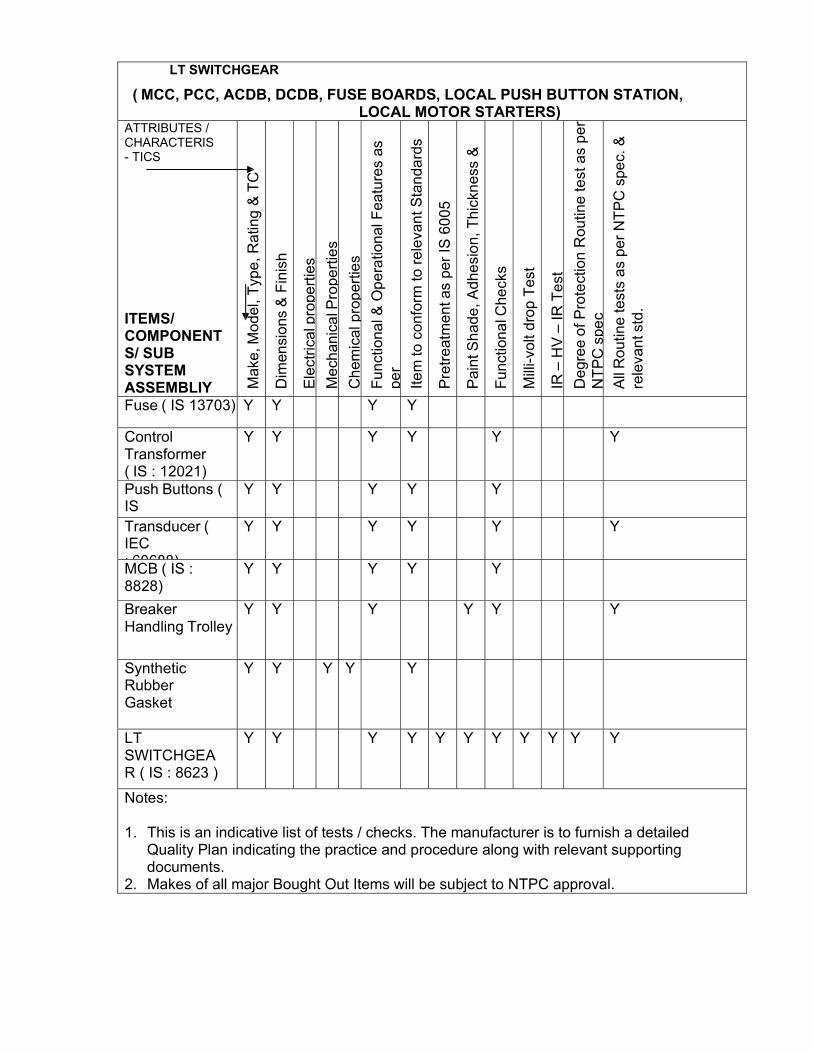
LT SWITCHGEAR
( MCC, PCC, ACDB, DCDB, FUSE BOARDS, LOCAL PUSH BUTTON STATION, LOCAL MOTOR STARTERS)
ATTRIBUTES / CHARACTERIS- TICS
ITEMS/ COMPONENT S/ SUB SYSTEM ASSEMBLIY
Mak
e, M
odel
, Typ
e, R
atin
g &
TC
Dim
ensi
ons
& F
inis
h
Ele
ctric
al p
rope
rties
Mec
hani
cal P
rope
rties
Che
mic
al p
rope
rties
Func
tiona
l & O
pera
tiona
l Fea
ture
s as
pe
r
Item
to c
onfo
rm to
rele
vant
Sta
ndar
ds
Pre
treat
men
t as
per I
S 6
005
Pai
nt S
hade
, Adh
esio
n, T
hick
ness
&
Func
tiona
l Che
cks
Milli
-vol
t dro
p Te
st
IR –
HV
– IR
Tes
t
Deg
ree
of P
rote
ctio
n R
outin
e te
st a
s pe
r N
TPC
spe
c
All
Rou
tine
test
s as
per
NTP
C s
pec.
&
rele
vant
std
.
Fuse ( IS 13703) Y Y Y Y
Control Transformer ( IS : 12021)
Y Y Y Y Y Y
Push Buttons ( IS
Y Y Y Y Y
Transducer ( IEC : 60688)
Y Y Y Y Y Y
MCB ( IS : 8828)
Y Y Y Y Y
Breaker Handling Trolley
Y Y Y Y Y Y
Synthetic Rubber Gasket
Y Y Y Y Y
LT SWITCHGEAR ( IS : 8623 )
Y Y Y Y Y Y Y Y Y Y Y
Notes: 1. This is an indicative list of tests / checks. The manufacturer is to furnish a detailed
Quality Plan indicating the practice and procedure along with relevant supporting documents.
2. Makes of all major Bought Out Items will be subject to NTPC approval.
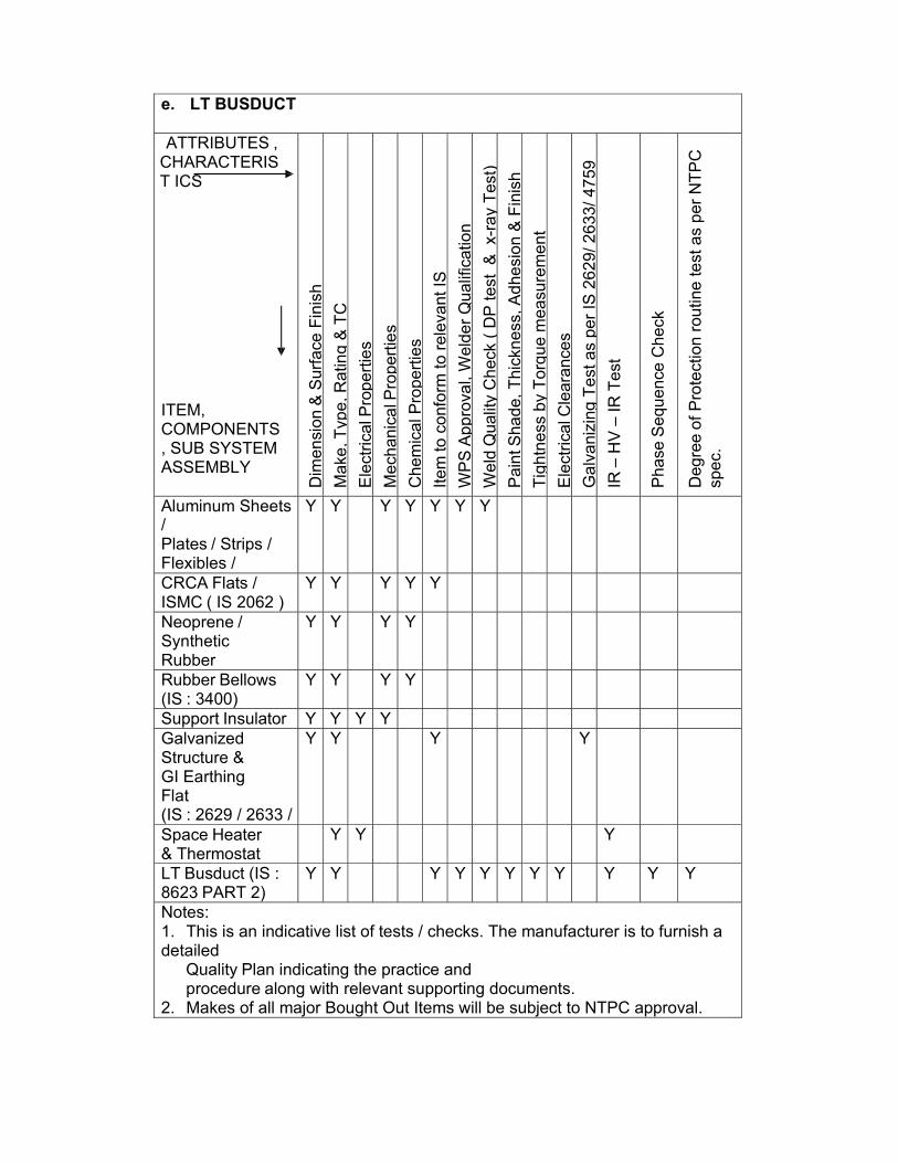
e. LT BUSDUCT
ATTRIBUTES , CHARACTERIST ICS
ITEM, COMPONENTS, SUB SYSTEM ASSEMBLY
Dim
ensi
on &
Sur
face
Fin
ish
Mak
e, T
ype,
Rat
ing
& TC
Ele
ctric
al P
rope
rties
Mec
hani
cal P
rope
rties
Che
mic
al P
rope
rties
Item
to c
onfo
rm to
rele
vant
IS
WP
S A
ppro
val,
Wel
der Q
ualif
icat
ion
Wel
d Q
ualit
y C
heck
( D
P te
st &
x-r
ay T
est)
Pai
nt S
hade
, Thi
ckne
ss, A
dhes
ion
& F
inis
h
Tigh
tnes
s by
Tor
que
mea
sure
men
t
Ele
ctric
al C
lear
ance
s
Gal
vani
zing
Tes
t as
per I
S 2
629/
263
3/ 4
759
IR –
HV
– IR
Tes
t
Pha
se S
eque
nce
Che
ck
Deg
ree
of P
rote
ctio
n ro
utin
e te
st a
s pe
r NTP
C
spec
.
Aluminum Sheets / Plates / Strips / Flexibles /
Y Y Y Y Y Y Y
CRCA Flats / ISMC ( IS 2062 )
Y Y Y Y Y
Neoprene / Synthetic Rubber
Y Y Y Y
Rubber Bellows (IS : 3400)
Y Y Y Y
Support Insulator Y Y Y Y Galvanized Structure & GI Earthing Flat (IS : 2629 / 2633 /
Y Y Y Y
Space Heater & Thermostat
Y Y Y
LT Busduct (IS : 8623 PART 2)
Y Y Y Y Y Y Y Y Y Y Y
Notes: 1. This is an indicative list of tests / checks. The manufacturer is to furnish a detailed
Quality Plan indicating the practice and procedure along with relevant supporting documents.
2. Makes of all major Bought Out Items will be subject to NTPC approval.
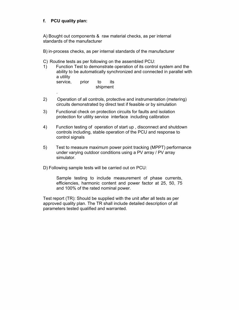
f. PCU quality plan: A) Bought out components & raw material checks, as per internal standards of the manufacturer
B) in-process checks, as per internal standards of the manufacturer
C) Routine tests as per following on the assembled PCU: 1) Function Test to demonstrate operation of its control system and the
ability to be automatically synchronized and connected in parallel with a utility service, prior to its shipment.
2) Operation of all controls, protective and instrumentation (metering) circuits demonstrated by direct test if feasible or by simulation
3) Functional check on protection circuits for faults and isolation protection for utility service interface including calibration
4) Function testing of operation of start up , disconnect and shutdown
controls including, stable operation of the PCU and response to control signals
5) Test to measure maximum power point tracking (MPPT) performance
under varying outdoor conditions using a PV array / PV array simulator.
D) Following sample tests will be carried out on PCU:
Sample testing to include measurement of phase currents, efficiencies, harmonic content and power factor at 25, 50, 75 and 100% of the rated nominal power.
Test report (TR): Should be supplied with the unit after all tests as per approved quality plan. The TR shall include detailed description of all parameters tested qualified and warranted.
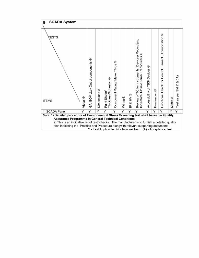
g. SCADA System
TESTS
ITEMS
Vis
ual ®
GA,
BO
M ,L
ay O
ut o
f com
pone
nts
®
Dim
ensi
ons
®
Pai
nt S
hade
/ Th
ickn
ess/
Adh
esio
n ®
Com
pone
nt R
atin
g/ M
ake
/ Typ
e ®
Wiri
ng ®
IR &
HV
®
Rev
iew
of T
C fo
r ins
trum
ents
/ Dev
ices
/ Rec
orde
rs,
Indi
cato
rs/ M
osai
c Ite
ms/
Tra
nsdu
cers
®
Acc
essi
bilit
y of
TBS
/ Dev
ices
®
Illum
inat
ion
®
Func
tiona
l Che
ck fo
r Con
trol E
lem
ent ,
Ann
unci
atio
n ®
Mim
ic ®
Test
as
per S
td ®
& (
A)
1. SCADA Panel Y Y Y Y Y Y Y Y Y Y Y Y YNote: 1) Detailed procedure of Environmental Stress Screening test shall be as per Quality
Assurance Programme in General Technical Conditions 2) This is an indicative list of test/ checks. The manufacturer is to furnish a detailed quality plan indicating the Practice and Procedure alongwith relevant supporting documents.
Y - Test Applicable , ® - Routine Test (A) - Acceptance Test
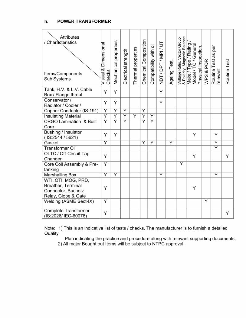
h. POWER TRANSFORMER
Attributes / Characteristics
Items/Components Sub Systems
Vis
ual &
Dim
ensi
onal
C
heck
s
Mec
hani
cal p
rope
rties
Ele
ctric
al s
treng
th
Ther
mal
pro
perti
es
Che
mic
al C
ompo
sitio
n
Com
patib
ility
with
oil
ND
T / D
PT
/ MP
I / U
T
Age
ing
Test
.
Vol
tage
Rat
io, V
ecto
r Gro
up
& P
olar
ity, M
agne
tic B
alan
ce
Mak
e / T
ype
/ Rat
ing
/ M
odel
/ TC
/ G
ener
al
Phy
sica
l Ins
pect
ion.
W
PS
& P
QR
R
outin
e Te
st a
s pe
r re
leva
nt
Rou
tine
Test
Tank, H.V. & L.V. Cable Box / Flange throat Y Y Y
Conservator / Radiator / Cooler / Y Y Y
Copper Conductor (IS:191) Y Y Y Y Insulating Material Y Y Y Y Y Y CRGO Lamination & Built Core
Y Y Y Y Y
Bushing / Insulator ( IS:2544 / 5621) Y Y
Y Y
Gasket Y Y Y Y Y Transformer Oil Y OLTC / Off-Circuit Tap Changer Y
Y Y
Core Coil Assembly & Pre- tanking
Y Y
Marshalling Box Y Y Y Y WTI, OTI, MOG, PRD, Breather, Terminal Connector, Bucholz Relay, Globe & Gate
Y
Y
Welding (ASME Sect-IX) Y Y
Complete Transformer (IS:2026/ IEC-60076) Y Y
Note: 1) This is an indicative list of tests / checks. The manufacturer is to furnish a detailed Quality
Plan indicating the practice and procedure along with relevant supporting documents.2) All major Bought out Items will be subject to NTPC approval.
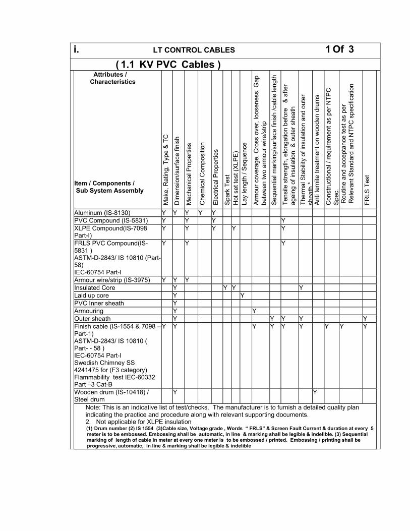
i. LT CONTROL CABLES 1 Of 3
( 1.1 KV PVC Cables ) Attributes /
Characteristics Item / Components / Sub System Assembly
Mak
e, R
atin
g, T
ype
& T
C
Dim
ensi
on/s
urfa
ce fi
nish
M
echa
nica
l Pro
perti
es
Che
mic
al C
ompo
sitio
n
Ele
ctric
al P
rope
rties
S
park
Tes
t H
ot s
et te
st (X
LPE
) La
y le
ngth
/ S
eque
nce
Arm
our c
over
age,
Cro
ss o
ver,
loos
enes
s, G
ap
betw
een
two
arm
our w
ire/s
trip
Sequ
entia
l mar
king
/sur
face
fini
sh /c
able
leng
th
Tens
ile s
treng
th, e
long
atio
n be
fore
&
afte
r ag
eing
of i
nsul
atio
n &
oute
r she
ath
Ther
mal
Sta
bilit
y of
insu
latio
n an
d ou
ter
shea
th*
Ant
i ter
nite
trea
tmen
t on
woo
den
drum
s C
onst
ruct
iona
l / re
quire
men
t as
per N
TPC
S
pec.
R
outin
e an
d ac
cept
ance
test
as
per
Rel
evan
t Sta
ndar
d an
d N
TPC
spe
cific
atio
n
FRLS
Tes
t
Aluminum (IS-8130) Y Y Y Y Y PVC Compound (IS-5831) Y Y Y Y XLPE Compound(IS-7098 Part-I)
Y Y Y Y Y
FRLS PVC Compound(IS- 5831 ) ASTM-D-2843/ IS 10810 (Part- 58) IEC-60754 Part-I
Y Y Y
Armour wire/strip (IS-3975) Y Y Y Insulated Core Y Y Y Y Laid up core Y Y PVC Inner sheath Y Armouring Y Y Outer sheath Y Y Y Y YFinish cable (IS-1554 & 7098 – Part-1) ASTM-D-2843/ IS 10810 ( Part- - 58 ) IEC-60754 Part-I Swedish Chimney SS 4241475 for (F3 category) Flammability test IEC-60332 Part –3 Cat-B
Y Y Y Y Y Y Y Y Y
Wooden drum (IS-10418) / Steel drum
Y Y
Note: This is an indicative list of test/checks. The manufacturer is to furnish a detailed quality plan indicating the practice and procedure along with relevant supporting documents. 2. Not applicable for XLPE insulation (1) Drum number (2) IS 1554 (3)Cable size, Voltage grade , Words “ FRLS” & Screen Fault Current & duration at every 5meter is to be embossed. Embossing shall be automatic, in line & marking shall be legible & indelible. (3) Sequential marking of length of cable in meter at every one meter is to be embossed / printed. Embossing / printing shall be progressive, automatic, in line & marking shall be legible & indelible
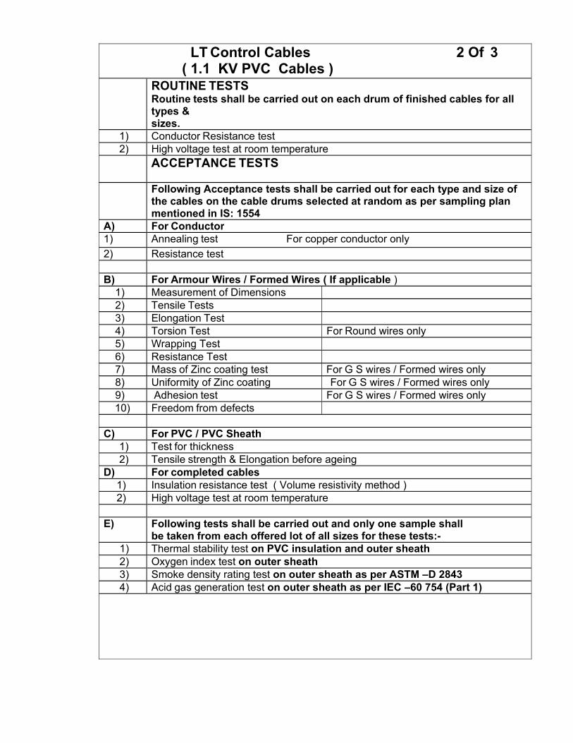
LT Control Cables 2 Of 3 ( 1.1 KV PVC Cables )
ROUTINE TESTS Routine tests shall be carried out on each drum of finished cables for all types & sizes.
1) Conductor Resistance test 2) High voltage test at room temperature
ACCEPTANCE TESTS
Following Acceptance tests shall be carried out for each type and size of the cables on the cable drums selected at random as per sampling plan mentioned in IS: 1554
A) For Conductor 1) Annealing test For copper conductor only 2) Resistance test
B) For Armour Wires / Formed Wires ( If applicable )
1) Measurement of Dimensions 2) Tensile Tests 3) Elongation Test 4) Torsion Test For Round wires only 5) Wrapping Test 6) Resistance Test 7) Mass of Zinc coating test For G S wires / Formed wires only 8) Uniformity of Zinc coating For G S wires / Formed wires only 9) Adhesion test For G S wires / Formed wires only 10) Freedom from defects
C) For PVC / PVC Sheath
1) Test for thickness 2) Tensile strength & Elongation before ageing
D) For completed cables 1) Insulation resistance test ( Volume resistivity method ) 2) High voltage test at room temperature
E) Following tests shall be carried out and only one sample shall
be taken from each offered lot of all sizes for these tests:- 1) Thermal stability test on PVC insulation and outer sheath 2) Oxygen index test on outer sheath 3) Smoke density rating test on outer sheath as per ASTM –D 2843 4) Acid gas generation test on outer sheath as per IEC –60 754 (Part 1)
LT Control Cables 3 Of 3 ( 1.1 KV PVC Cables )
F) Ageing test on PVC insulation and PVC outer sheath as per following
In case of regular manufacturers:- Samples as per relevant IS from every size per type of cable in the offered lot shall be testedfor tensile strength & elongation (before ageing). The values will be compared with corresponding values mentioned in the type test report accepted by NTPC. In case values of tensile strength & elongation (before ageing) are within + /- 15% of the type test reports then 1 sample per type of cable of offered lot will be put on accelerated ageing test. The accelerated ageing test procedure: sample to be put in air oven at temperature of 130^c +/- 2^c for 5 hours, tensile strength & elongation acceptance norms as per
In case of new manufacturers / suppliers (supplying first time to NTPC through corporate contract):- Samples as per relevant IS from every size per type of cable in the offered lot shall be tested for tensile strength & elongation (before ageing). The values will be compared with corresponding values mentioned in the type test report accepted by NTPC. In case values of tensile strength & elongation (before ageing) are not within + /- 15% of the type test reports then sample from that particular cable size will be put on ageing test as per relevant IS. However not withstanding above condition, 1 sample per cable type of offered lot will be put on ageing test as per relevant IS.
G) Flammability test as per IEC 60332 - Part- 3 (Category- B) on completed cable as per following sampling plan.
The test shall be carried out on every size & type of control cable offered for inspection as an acceptance test. This test will be carried out using composite sampling i.e. irrespective of sizes of cables of a particular type, may be tested together as per calculations in line with the IEC ( all sizes will be covered)
I) Following tests shall be carried on one length of each size of offered lot: Surface finish, length measurement, sequence of cores, armour coverage, Gap between two
consecutive armour wires / formed wires
j. LT Power Cables 1 Of 3
1.1 KV PVC & XLPE Cables Attributes /
Characteristics Item / Components / Sub System Assembly
Mak
e, R
atin
g, T
ype
& T
C
Dim
ensi
on/s
urfa
ce fi
nish
M
echa
nica
l Pro
perti
es
Che
mic
al C
ompo
sitio
n
Ele
ctric
al P
rope
rties
S
park
Tes
t H
ot s
et te
st (X
LPE
) La
y le
ngth
/ Se
quen
ce
Arm
our c
over
age,
Cro
ss o
ver,
loos
enes
s, G
ap
betw
een
two
arm
our w
ire/s
trip
Seq
uent
ial m
arki
ng/s
urfa
ce fi
nish
/cab
le le
ngth
Te
nsile
stre
ngth
, elo
ngat
ion
befo
re
& a
fter
agei
ng o
f ins
ulat
ion
& o
uter
she
ath
Ther
mal
Sta
bilit
y of
insu
latio
n an
d ou
ter
shea
th *
A
nti t
erni
te tr
eatm
ent o
n w
oode
n dr
ums
Con
stru
ctio
nal /
requ
irem
ent a
s pe
r NTP
C
Spe
c.
Rou
tine
and
acce
ptan
ce te
st a
s pe
r R
elev
ant S
tand
ard
and
NTP
C s
peci
ficat
ion
FRLS
Tes
t
Aluminum (IS-8130) Y Y Y Y Y PVC Compound (IS-5831) Y Y Y Y XLPE Compound(IS-7098 Part- I)
Y Y Y Y Y
FRLS PVC Compound(IS-5831 ) ASTM-D-2843/ IS 10810 (Part- 58) IEC-60754 Part-I
Y Y Y
Armour wire/strip (IS-3975) Y Y Y Insulated Core Y Y Y Y Laid up core Y Y PVC Inner sheath Y Armouring Y Y Outer sheath Y Y Y Y YFinish cable (IS-1554 & 7098 – Part-1) ASTM-D-2843/ IS 10810 ( Part- - 58 ) IEC-60754 Part-I Swedish Chimney SS 4241475 for (F3 category) Flammability test IEC-60332 Part –3 Cat-B
Y Y Y Y Y Y Y Y Y
Wooden drum (IS-10418) / Steel drum
Y Y
Note: This is an indicative list of test/checks. The manufacturer is to furnish a detailed quality plan indicating the practice and procedure along with relevant supporting documents. 2. Not applicable for XLPE insulation (1) Drum number (2) IS 7098-Part II (3)Cable size, Voltage grade , Words “ FRLS” & Screen Fault Current & duration at every 5 meter is to be embossed. Embossing shall be automatic, in line & marking shall be legible & indelible. (3) Sequential marking of length of cable in meter at every one meter is to be embossed / printed. Embossing / printing shall be progressive, automatic, in line & marking shall be legible & indelible
LT Power Cables 2 Of 3
1.1 KV PVC & XLPE Cables ROUTINE TESTS
Routine tests shall be carried out on each drum of finished cables for all types & sizes. Following shall constitute routine tests:
1) Conductor Resistance test 2) High voltage test at room temperature
ACCEPTANCE TESTS
Following Acceptance tests shall be carried out for each type and size of the cables on the cable drums selected at random as per sampling plan mentioned in IS: 1554 Part 1 & IS 7098 Part-I
A) For Conductor 1) Annealing test For copper conductor only 2) Tensile test For aluminium conductor only 3) Wrapping test For aluminium conductor only 4) Resistance test
B) For Armour Wires / Formed Wires ( If applicable )
1) Measurement of Dimensions 2) Tensile Tests 3) Elongation Test 4) Torsion Test For Round wires only 5) Wrapping Test 6) Resistance Test 7) Mass of Zinc coating test For G S wires / Formed wires only 8) Uniformity of Zinc coating For G S wires / Formed wires only 9) Adhesion test For G S wires / Formed wires only 10) Freedom from defects
C) For PVC / XLPE insulation & PVC Sheath
1) Test for thickness 2) Hot set test For XLPE insulation only 3) Tensile strength & Elongation before ageing
D) For completed cables 1) Insulation resistance test ( Volume resistivity method ) 2) High voltage test at room temperature
LT Power Cables 3 Of 3
1.1 KV PVC & XLPE Cables E) Following tests shall be carried out and only one sample shall
be taken from each offered lot of all sizes for these tests:-
1) Thermal stability test on PVC insulation and outer sheath 2) Oxygen index test on outer sheath3) Smoke density rating test on outer sheath as per ASTM –D 2843 4) Acid gas generation test on outer sheath as per IEC –60 754 (Part 1)
F) Ageing test on PVC insulation and PVC outer sheath as per
In case of regular manufacturers:- Samples as per relevant IS from every size per type of cable in the offered lot shallbe tested for tensile strength & elongation (before ageing). The values will be compared with corresponding values mentioned in the type test report accepted by NTPC. In case values of tensile strength & elongation (before ageing) are within + /- 15% of the type test reports then 1 sample per type of cable of offered lot will be put on accelerated ageing test. The
In case of new manufacturers / suppliers (supplying first time to NTPCthrough corporate contract):- Samples as per relevant IS from every size per type of cable in the offered lot shall be tested for tensile strength & elongation (before ageing). The values will be compared with corresponding values mentioned in the type test report accepted by NTPC. In case values of tensile strength & elongation (before ageing) are not within + /- 15% of the type test reports then sample from that particular cable size will be put on ageing test as per relevant IS. However not withstanding above condition, 1
G) Flammability test as per IEC 60332 - Part- 3 (Category- B) on completed cable as per following sampling plan.
The test shall be carried out on every size & type of control cable offered for inspection as an acceptance test. This test will be carried out using composite sampling i.e. irrespective of sizes of cables of a particular type, may be tested together as per
I) Following tests shall be carried on one length of each size of Surface finish, length measurement, sequence of cores, armour coverage, Gap
between two
k. HT Power Cables 1 Of 3
Attributes / Characteristics
Item / Components / Sub System Assembly
Mak
e, T
ype,
Rat
ing
& T
.C
Dim
ensi
on/s
urfa
ce fi
nish
Mec
hani
al p
rope
rties
Che
mic
al C
ompo
sitio
n
Spa
rk T
est(a
s ap
plic
able
)
Cur
ing
Pro
perti
es
Ele
ctric
al p
rope
rties
Hot
Set
Tes
t/ E
ccen
trici
ty &
Ova
lity
Lay
leng
th &
Seq
uenc
e
Arm
our c
over
age,
cro
ss o
ver,
loos
enes
s,ga
pbe
twee
ntw
ow
ire
Seq
uent
ial m
arki
ng/s
urfa
ce fi
nish
/ ca
ble
leng
th
T.S
& e
long
atio
n be
fore
& a
fter a
gein
g on
oute
rshe
ath
&in
sula
tion
Ther
mal
sea
bilit
y on
out
er s
heat
h
Met
allic
( C
u ) S
cree
ning
( If
app
licab
le)
Ant
i ter
mite
coa
ting
on w
oode
n dr
ums
Con
stru
ctio
nal r
equi
rem
ents
feat
ure
as
per
Rou
tine
& A
ccep
tanc
e Te
st a
s pe
r re
leva
ntst
anda
rd&
NTP
C
FRLS
Tes
t
Aluminium (IS-8130) Y Y Y Y Y Semiconducting Compound
Y Y Y Y
XLPE Compound (IS-7098 Part-II)
Y Y Y Y Y
FRLS PVC Compound (IS-5831, ASTM-D2843, IS10810( Part 58)
Y Y Y Y Y
Triple Extrusion & curing /Manufacturing of Core
Y Y Y Y
Copper Tape Y Y Y Y Polyster tape Y Y Armour wire/strip Y Y Y Copper tapping Y Y Y Inner sheath Y Y Armouring Y Y Outer Sheathing Y Y Y Y Y YPower Cable (Finished) (IS : 7098 Part II, IEC : 60332 (Part 3 Cat. B), IS-5831, ASTM-D2843,
Y Y Y Y Y Y Y Y Y
Wooden drum(IS-10418) /Steel Drum
Y Y
Notes: 3. This is an indicative list of tests / checks. The manufacturer is to furnish a detailed Quality Plan indicating
the practice and procedure along with relevant supporting documents. 4. Make of all major Bought Out Items will be subject to NTPC approval. 5. (1) Drum number (2) IS 7098-Part II (3)Cable size, Voltage grade , Words “ FRLS” & Screen Fault Current & duration at every 5 meter
is to be embossed. Embossing shall be automatic, in line & marking shall be legible & indelible. (3) Sequential marking of length of cable in
HT Power Cables 2 Of 3 ROUTINE TESTS
Routine tests shall be carried out on each drum of finished cables for all types & sizes. Following shall constitute routine tests:
1) Conductor Resistance test 2) High voltage test
3) Partial discharge test ( for Screened cables only )
ACCEPTANCE TESTS Following Acceptance tests shall be carried out for each type and size of the cables on the cable drums selected at random as per sampling plan mentioned in IS: 7098 Part 1I A) For Conductor 1) Tensile Test 2) Wrapping Test 3) Resistance test
B) For Armour Wires / Formed Wires ( If applicable ) 1) Measurement of Dimensions 2) Tensile Tests 3) Elongation Test 4) Torsion Test For Round wires only 5) Wrapping Test 6) Resistance Test 7) Mass of Zinc coating test For G S wires / Formed
wires only 8) Uniformity of Zinc coating For G S wires / Formed
wires only 9) Adhesion test For G S wires / Formed
wires only 10) Freedom from defects
C) For XLPE insulation & PVC Sheath 1) Test for thickness 2) Tensile strength & Elongation before ageing 3) Hot set test (For XLPE insulation)
D) For completed cables 1) Insulation resistance test ( Volume resistivity method ) 2) High voltage test 3 Partial discharge test ( for Screened cables only )
HT Power Cables 3 Of 3
E) Following tests shall be carried out and only one sample shall be taken from each offered lot of all sizes for these tests:-
1) Thermal stability test on PVC insulation and outer sheath 2) Oxygen index test on outer sheath 3) Smoke density rating test on outer sheath as per ASTM –D 2843 4) Acid gas generation test on outer sheath as per IEC –60 754 (Part 1) 5) Flammability test as per IEC 60332 - Part- 3 (Category- B) on completed cable
F) Ageing test on XLPE insulation and PVC outer sheath as per
following: In case of regular manufacturers:- Samples as per relevant IS from every size per type of cable in the offered lot shall be tested for tensile strength & elongation (before ageing). The values will be compared with corresponding values mentioned in the type test report accepted by NTPC. In case values of tensile strength & elongation (before ageing) are within + /- 15% of the type test reports then 1 sample per type of cable of offered lot will be put on accelerated ageing test. The accelerated ageing test procedure: sample to be put in air oven at temperature of 130^c +/- 2^c for 5 hours, tensile strength & elongation acceptance norms as per relevant IS. However in case the tensile strength and elongation values are not within +/- 15% of type test values then ageing test will be carried out on that particular size of cable of offered lot as per relevant IS.
In case of new manufacturers / suppliers (supplying first time to NTPC through corporate contract):-
Samples as per relevant IS from every size per type of cable in the offered lot shall be tested for tensile strength & elongation (before ageing). The values will be compared with corresponding values mentioned in the type test report accepted by NTPC. In case values of tensile strength & elongation (before ageing) are not within + /- 15% of the type test reports then sample from that particular cable size will be put on ageing test as per relevant IS. However not withstanding above condition, 1 sample per cable type of offered lot will be put on ageing test as per relevant IS.
G) Following tests shall be carried on one length of each size of offered lot:
1) Surface finish, length measurement, sequence of cores, armour coverage, Gap between two consecutive armour wires / formed wires
2) Measurement of Eccentricity & Ovality
l. Civil Works
QUALITY ASSURANCE AND INSPECTION FOR CIVIL WORKS INTRODUCTION This part of the specification covers the sampling, testing and quality assurance requirement (including construction tolerances and acceptance
criteria) for all civil and structural works covered in this specification.
This part of the technical specification shall be read in conjunction with other parts of the technical specifications, general technical requirements &
erection conditions of the contract which covers common QA requirements. Wherever IS code or standards have been referred they shall be the latest
revisions.
The rate for respective items of work or price shall include the cost for all works, activities, equipment, instrument, personnel, material etc. whatsoever associated to comply with sampling, testing and quality assurance requirement including construction tolerances and acceptance criteria and as specified in subsequent clauses of this part of the technical specifications. The QA and QC activities in all respects as specified in the technical specifications/ drawings / data sheets / quality plans / contract documents shall be carried out at no extra cost to the owner. The contractor shall prepare detailed construction and erection methodology scheme which shall be compatible to the requirements of the desired progress of work execution, quality measures, prior approvals if any and the same shall be got approved by the Engineer. If required, work methodology may be revised/ reviewed at every stage of execution of work at site, to suit the site conditions by the contractor at no extra cost to the owner. QA AND QC MANPOWER The contractor shall nominate one overall QA coordinator for the contract detailing the name, designation, contact details and address at the time of post bid discussions. All correspondence related to Quality Assurance shall be addressed by the contractor’s QA coordinator to BHEL and BHEL/NTPC. BHEL and BHEL/NTPC shall address all correspondence related to Quality issues to the contractor’s QA coordinator. The contractor’s QA coordinator shall be responsible for co-ordination of Quality activities between various divisions of the contractor and their sub-Contractors on one hand & with BHEL and BHEL/NTPC on the other hand. The contractor shall appoint a dedicated, experienced and competent QA&QC in-charge at site, preferably directly reporting to the Project Manager, supported as necessary by experienced personnel, to ensure the effective implementation of the approved QAP. The contractor shall finalize and submit a deployment schedule of QA&QC personnel along with their details to BHEL and BHEL/NTPC for approval/ acceptance and further shall ensure their availability well before the start of the concern activity. Contractor shall furnish the QA & QC manpower deployment schedule based on the quantum of work. It is essential to post qualified QA & QC man power at site so as to strictly monitor quality of works and also arrange for compliance. SAMPLING AND TESTING OF CONSTRUCTION MATERIALS
The method of sampling for testing of construction materials and work / job samples shall be as per the relevant IS / standards / codes and in line with the requirements of the technical specifications / quality plans. All samples shall be jointly drawn, signed and sealed wherever required, by the contractor and the engineer or his authorized representative. The contractor shall carry out testing in accordance with the relevant IS / standards / codes and in line with the requirements of the technical specifications / quality plans. Where no specific testing procedure is mentioned, the tests shall be carried out as per the best prevalent engineering practices and to the directions of the Engineer. All testing shall be done in the presence of the engineer or his authorized representative in a NABL accredited / Govt. Laboratory acceptable to BHEL and BHEL/NTPC. This includes all IITs, NCB, CSMRS, reputed government / autonomous laboratories / organizations, NITs and other reputed testing laboratories. The test samples for such test shall be jointly selected and sealed by the engineer and thereafter these shall be sent to the concerned laboratory through the covering letter signed by BHEL and BHEL/NTPC engineer. The test report along with the recommendations shall be obtained from the laboratories without delay and submitted to BHEL and BHEL/NTPC. Third Party Laboratory Testing: In case material test certificate are furnished for bought out items for civil works, these will be clearly correlated and be traceable with the batch no. and consignment note/ challans. Samples of bought out items shall be tested at third party lab if required by BHEL and/or NTPC. If contractors proposes to carry out testing of bought out items/ materials as per above, the same shall be done through the third party independent labs or any other lab acceptable to BHEL and NTPC. Contractor shall carry out concrete mix design, test on aggregates, cement, admixtures, fly ash at BHEL/NTPC accepted laboratories as mentioned in the technical specification. Sampling for testing building materials, all ingredients i.e. cement, coarse and fine aggregates, fly ash, water including admixtures required for concreting and other construction work shall be done for conducting tests as mentioned above. Sampling shall be done jointly with FQA engineers of BHEL and NTPC. These shall be sealed and sent to the testing agency/laboratory, Contractor shall submit all test reports along with their recommendations pertaining to mix design and suitability of use of building material, as mentioned above for BHEL and NTPC approval. PURCHASE AND SERVICE Structural steel supply in the scope of the contractor shall be procured from main steel producers like SAIL, TISCO, IISCO, RINL, Essar Steel, Ispat Industries, JSW Steel, Lloyds Steel, Jindal Steel & Power. In case of non-availability of some of the sections with main steel producers the contractor may propose to procure the sections from the re-rollers of the main steel producers, the name of such re-rollers will have to be cleared by corporate quality assurance of BHEL and BHEL/NTPC for which details such as BIS approval, main steel producer’s approval, past experience for production of sections of specified material, details of machines plants testing facilities etc., Confirmation that the process control and manufacturing of steel sections by re-rollers shall be same as that of main steel producers, that billets for re-rolling will be sourced from main steel producers only shall be furnished with regards to re-roller. Even after clearance of re-rollers, induction of billets with identified and correlated Mill test certificates (TC’s) in the process of re-rolling, sampling of steel, quality checks thereof and stamping of final product for further identification and correlation with TC’s prior to dispatch shall be the responsibility of the contractor and these shall be performed in presence of the authorized representative of the main Contractor. Reinforcement steel supply in the scope of the contractor shall be procured from main steel producers like SAIL, TISCO, IISCO, RINL, Essar Steel, Ispat Industries, JSW Steel, Lloyds Steel, Jindal Steel & Power, Jai Balaji Industries Ltd, Durgapur (for 8-40mm reinforcement steel) and mill test certificates (TC) is to be obtained and submitted to BHEL and BHEL/NTPC for co-relation. In case any size /diameter specified is not available with main steel producers and are proposed to be supplied from the conversion agent of the main steel producer the name of such conversion agent/ re-roller shall have to be approved by BHEL and BHEL/NTPC for which details such as BIS approval, Main steel producer’s approval, Past experience

for production of sections of specified material, details of machines, plants testing facilities etc., and confirmation that the process control and manufacturing of steel sections by re-rollers is the same as that of main steel producers, that billets for re-rolling are sourced from main steel producers only shall be furnished with regards to re-roller. FIELD AND MANUFACTURING QUALITY PLAN Well before the start of the work, the contractor shall prepare and submit the Field Quality Plans (FQP) on the format No. QS-01-QAI-P-09/F2-R1, and obtain approval of BHEL and BHEL/NTPC, which shall detail out for all the works, equipments, services, quality practices and procedures etc in line with the requirement of the technical specifications to be followed by the contractor at site. This FQP shall cover for all the items / activities covered in the contract / schedule of items required, right from material procurement to completion of the work at site. An Indicative Field Quality Plan for civil works is enclosed at Annexure I (Indicative FQP for civil works) & Annexure II (Indicative FQP for structural steel works). Contractor shall submit and finalize FQP in given BHEL/NTPC-format in line with the FQP enclosed at technical specification covering all the items indicating all the test including frequency of the tests within 2 week from the date of PO. FQPs shall detail out all the quality procedures, practices and checks to be followed at the site right from the receipt of material to erection/construction stage of concern activity. Details of storage and preservation procedures/ fabrication/ erection/ installation/ construction/ finishing/ monitoring, field tests, acceptance tests procedures etc. shall be furnished in FQP for civil works and structural steel works in line with the technical specifications. In the approved FQP and MQP, BHEL shall identify Customer Hold Points (CHP) beyond which work shall not proceed without the consent of BHEL in writing. No materials shall be dispatched from the Manufacturer’s works before the is accepted subsequent to final inspection including verification of records of all previous tests and is authorized for dispatch by issue of Material Clearance/CHP. LABORATORY AND FIELD TEST Based on finalised work schedule and item wise quantum of work, and in line with the approved FQP, they shall submit a schedule of tests required to be conducted weekly and shall accordingly deploy the manpower, equipment and field laboratory facilities. QA & QC LABORATORY SET-UP Contractor shall set-up QA&QC laboratory at site, in line with the technical specification requirements and them functional. Contractor shall deploy the minimum no. of laboratory equipments required for Field QA&QC laboratory. An indicative list is given below. The required no. of sets of laboratory equipments and QA&QC manpower shall be deployed at least 15 days prior to start of the concern test/activity at site. Contractor shall undertake joint sampling of material with BHEL and BHEL/NTPC site FQAs for the tests proposed to be conducted at third party laboratory well in advance to ensure availability of test results/report well before the start of concern activity/work. S.No. EQUIPMENT APPROXIMATE Nos. 1 Cube moulds for cement testing 12 2 Sieve shaker 1 3 Sieves for sand, coarse and fine aggregate 1 set for each 4 Sieves for coarse aggregates 1 set 5 Slump testing equipment 6 sets 6 Oven 5 7 Physical balance 1 8 Thermometer 4 9 Burret 2
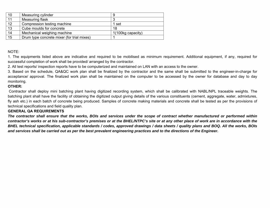
10 Measuring cylinder 9 11 Measuring flask 3 12 Compression testing machine 1 set 13 Cube moulds for concrete 18 14 Mechanical weighing machine 1(100kg capacity) 15 Drum type concrete mixer (for trial mixes) 1 NOTE: 1. The equipments listed above are indicative and required to be mobilised as minimum requirement. Additional equipment, if any, required for successful completion of work shall be provided/ arranged by the contractor. 2. All test reports/ inspection reports have to be computerized and maintained on LAN with an access to the owner. 3. Based on the schedule, QA&QC work plan shall be finalized by the contractor and the same shall be submitted to the engineer-in-charge for acceptance/ approval. The finalized work plan shall be maintained on the computer to be accessed by the owner for database and day to day monitoring. OTHER: Contractor shall deploy mini batching plant having digitized recording system, which shall be calibrated with NABL/NPL traceable weights. The batching plant shall have the facility of obtaining the digitized output giving details of the various constituents (cement, aggregate, water, admixtures, fly ash etc.) in each batch of concrete being produced. Samples of concrete making materials and concrete shall be tested as per the provisions of technical specifications and field quality plan. GENERAL QA REQUIREMENTS The contractor shall ensure that the works, BOIs and services under the scope of contract whether manufactured or performed within contractor’s works or at his sub-contractor’s premises or at the BHEL/NTPC’s site or at any other place of work are in accordance with the BHEL technical specification, applicable standards / codes, approved drawings / data sheets / quality plans and BOQ. All the works, BOIs and services shall be carried out as per the best prevalent engineering practices and to the directions of the Engineer.
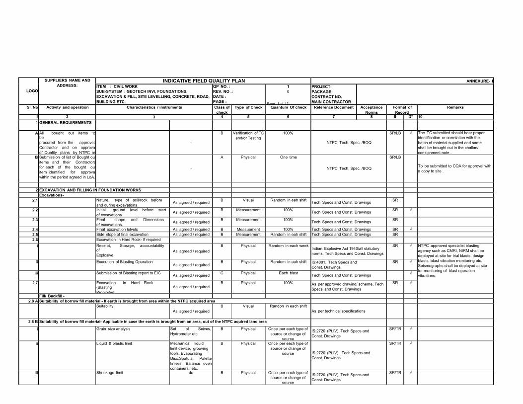
LOGO SUPPLIERS NAME AND
ADDRESS: INDICATIVE FIELD QUALITY PLAN ANNEXURE- I ITEM : CIVIL WORK SUB-SYSTEM : GEOTECH INVI, FOUNDATIONS, EXCAVATION & FILL, SITE LEVELLING, CONCRETE, ROAD, BUILDING ETC.
QP NO. :REV. NO .: DATE : PAGE :
10
Page 1 of 12
PROJECT: PACKAGE: CONTRACT NO. MAIN CONTRACTOR
Sl. No Activity and operation Characteristics / instruments Class ofcheck
Type of Check Quantum Of check Reference Document Acceptance Norms
Format of Record
Remarks
1 2 3 4 5 6 7 8 9 D* 101 GENERAL REQUIREMENTS A All bought out items to
be procured from the approvedContractor and on approvalof Quality plans by NTPC as
-
B Verification of TCand/or Testing
100% NTPC Tech. Spec. /BOQ
SR/LB √ The TC submitted should bear properidentification or correlation with the batch of material supplied and same shall be brought out in the challan/ consignment note .
B Submission of list of Bought outitems and their Contractorsfor each of the bought outitem identified for approvalwithin the period agreed in LoA.
-
A Physical One time
NTPC Tech. Spec. /BOQ SR/LB
To be submitted to CQA for approval with a copy to site .
2 EXCAVATION AND FILLING IN FOUNDATION WORKS Excavations- 2.1 Nature, type of soil/rock before
and during excavations As agreed / required B Visual Random in eah shift Tech Specs and Const. Drawings SR 2.2 Initial ground level before start
of excavations As agreed / required B Measurement 100% Tech Specs and Const. Drawings SR √ 2.3 Final shape and Dimensions
of excavations. As agreed / required B Measurement 100% Tech Specs and Const. Drawings SR 2.4 Final excavation lelvels As agreed / required B Measuement 100% Tech Specs and Const. Drawings SR √2.5 Side slope of final excavation As agreed / required B Measurement Random in eah shift Tech Specs and Const. Drawings SR2.6 Excavation in Hard Rock- If required
i Receipt, Storage, accountability of Explosive As agreed / required
B Physical Random in each week Indian Explosive Act 1940/all statutory norms, Tech Specs and Const. Drawings
SR √ NTPC approved specialist blasting agency such as CMRI, NIRM shall be deployed at site for trial blasts, design blasts, blast vibration monitoring etc. Seismographs shall be deployed at site for monitoring of blast operation vibrations.
ii Execution of Blasting Operation As agreed / required
B Physical Random in eah shift IS:4081, Tech Specs and Const. Drawings
SR √
iii Submission of Blasting report to EIC As agreed / required C Physical Each blast Tech Specs and Const. Drawings √
2.7 Excavation in Hard Rock (Blasting Prohibited)
As agreed / requiredB Physical 100% As per approved drawing/ scheme, Tech
Specs and Const. Drawings SR √
Fill/ Backfill - 2.8 A Suitability of borrow fill material - If earth is brought from area within the NTPC acquired area
Suitability As agreed / required
B Visual Randon in each shift As per technical specifications
2.8 B Suitability of borrow fill material- Applicable in case the earth is brought from an area, out of the NTPC aquired land area
i Grain size analysis Set of Seives, Hydrometer etc. B Physical Once per each type of
source or change of source
IS:2720 (Pt.IV), Tech Specs and Const. Drawings
SR/TR √ ii Liquid & plastic limit Mechanical liquid
limit device, grooving tools, Evaporating Disc,Spatula, Palette knives, Balance ovencontainers, etc.
B Physical Once per each type of source or change of
source IS:2720 (Pt.IV) , Tech Specs and Const. Drawings
SR/TR √
iii Shrinkage limit -do- B Physical Once per each type of source or change of
source
IS:2720 (Pt.IV), Tech Specs and Const. Drawings
SR/TR √
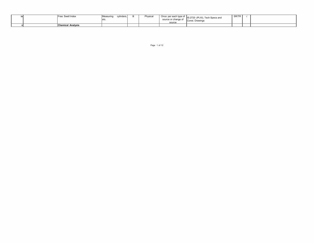
iv Free Swell Index Measuring cylinders, etc. B Physical Once per each type of
source or change of source
IS:2720 (Pt.XI), Tech Specs and Const. Drawings
SR/TR √ v Chemical Analysis
Page 1 of 12
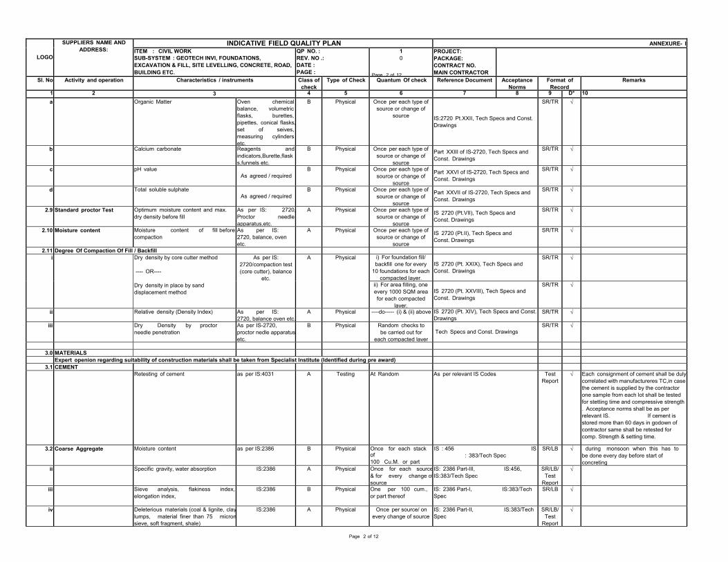
LOGO SUPPLIERS NAME AND
ADDRESS: INDICATIVE FIELD QUALITY PLAN ANNEXURE- I ITEM : CIVIL WORK SUB-SYSTEM : GEOTECH INVI, FOUNDATIONS, EXCAVATION & FILL, SITE LEVELLING, CONCRETE, ROAD, BUILDING ETC.
QP NO. :REV. NO .: DATE : PAGE :
10
Page 2 of 12
PROJECT: PACKAGE: CONTRACT NO. MAIN CONTRACTOR
Sl. No Activity and operation Characteristics / instruments Class ofcheck
Type of Check Quantum Of check Reference Document Acceptance Norms
Format of Record
Remarks
1 2 3 4 5 6 7 8 9 D* 10a Organic Matter Oven chemical
balance, volumetric flasks, burettes, pipettes, conical flasks,set of seives, measuring cylindersetc.
B Physical Once per each type of source or change of
source IS:2720 Pt.XXII, Tech Specs and Const. Drawings
SR/TR √
b Calcium carbonate Reagents and indicators,Burette,flask s,funnels etc.
B Physical Once per each type of source or change of
source
Part XXIII of IS-2720, Tech Specs and Const. Drawings
SR/TR √ c pH value
As agreed / requiredB Physical Once per each type of
source or change of source
Part XXVI of IS-2720, Tech Specs and Const. Drawings
SR/TR √ d Total soluble sulphate
As agreed / requiredB Physical Once per each type of
source or change of source
Part XXVII of IS-2720, Tech Specs and Const. Drawings
SR/TR √ 2.9 Standard proctor Test Optimum moisture content and max.
dry density before fill As per IS: 2720,Proctor needle apparatus,etc.
A Physical Once per each type of source or change of
source
IS 2720 (Pt.VII), Tech Specs and Const. Drawings
SR/TR √ 2.10 Moisture content Moisture content of fill before
compaction As per IS: 2720, balance, oven etc.
A Physical Once per each type of source or change of
source
IS 2720 (Pt.II), Tech Specs and Const. Drawings
SR/TR √ 2.11 Degree Of Compaction Of Fill / Backfill
i Dry density by core cutter method ---- OR----
Dry density in place by sand displacement method
As per IS: 2720/compaction test (core cutter), balance
etc.
A Physical i) For foundation fill/ backfill one for every
10 foundations for each compacted layer.
IS 2720 (Pt. XXIX), Tech Specs and Const. Drawings
SR/TR √
ii) For area filling, one every 1000 SQM area for each compacted
layer.
IS 2720 (Pt. XXVIII), Tech Specs and Const. Drawings
SR/TR √
ii Relative density (Density Index) As per IS: 2720, balance oven etc.
A Physical ----do----- (i) & (ii) above IS 2720 (Pt. XIV), Tech Specs and Const.Drawings
SR/TR √ iii Dry Density by proctor
needle penetration As per IS-2720, proctor nedle apparatusetc.
B Physical Random checks to be carried out for
each compacted layer Tech Specs and Const. Drawings SR/TR √
3.0 MATERIALS Expert openion regarding suitability of construction materials shall be taken from Specialist Institute (Identified during pre award)
3.1 CEMENT Retesting of cement as per IS:4031 A Testing At Random As per relevant IS Codes Test
Report√ Each consignment of cement shall be duly
correlated with manufactureres TC,in case the cement is supplied by the contractor one sample from each lot shall be tested for stetting time and compressive strength . Acceptance norms shall be as per relevant IS. If cement is stored more than 60 days in godown of contractor same shall be retested for comp. Strength & setting time.
3.2 Coarse Aggregate Moisture content as per IS:2386 B Physical Once for each stack of 100 Cu.M. or part
IS : 456 IS: 383/Tech Spec SR/LB √ during monsoon when this has to
be done every day before start of concreting
ii Specific gravity, water absorption IS:2386 A Physical Once for each source& for every change ofsource
IS: 2386 Part-III, IS:456, IS:383/Tech Spec SR/LB/
Test Report
√ iii Sieve analysis, flakiness index,
elongation index, IS:2386 B Physical One per 100 cum., or part thereof IS: 2386 Part-I, IS:383/Tech
Spec SR/LB √ iv Deleterious materials (coal & lignite, clay
lumps, material finer than 75 micronsieve, soft fragment, shale)
IS:2386 A Physical Once per source/ on every change of source IS: 2386 Part-II, IS:383/Tech
Spec SR/LB/ Test
Report
√
Page 2 of 12
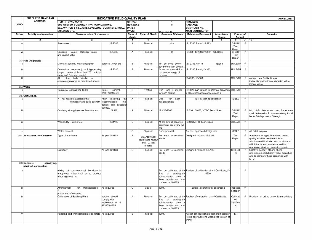
LOGO SUPPLIERS NAME AND
ADDRESS: INDICATIVE FIELD QUALITY PLAN ANNEXURE- I ITEM : CIVIL WORK SUB-SYSTEM : GEOTECH INVI, FOUNDATIONS, EXCAVATION & FILL, SITE LEVELLING, CONCRETE, ROAD, BUILDING ETC.
QP NO. :REV. NO .: DATE : PAGE :
10
Page 3 of 12
PROJECT: PACKAGE: CONTRACT NO. MAIN CONTRACTOR
Sl. No Activity and operation Characteristics / instruments Class ofcheck
Type of Check Quantum Of check Reference Document Acceptance Norms
Format of Record
Remarks
1 2 3 4 5 6 7 8 9 D* 10v Soundness IS:2386 A Physical -do- IS: 2386 Part-V, IS:383 SR/LB/
Test Report
√ vi Crushing value abrasion value
and impact value IS:2386 A Physical -do- IS:383, IS-2386 Part IV/Tech Spec SR/LB/ Test
Report
√ 3.3 Fine Aggregate
i Moisture content, water absorption balance , oven etc B Physical To be done every day before start of work IS: 2386 Part-III IS:383 SR/LB/TR √
ii Deleterious materials (coal & lignite, claylumps, material finer than 75 micronsieve, soft fragment, shale)
IS:2386 B Physical Once per source& for on every change of source
IS: 2386 Part-II, IS:383 SR/LB/TR √ iii All other tests similar to
coarse aggregates as mentioned above. IS-2386, IS-383 SR/LB/TR √ except test for flankiness index,elongation index, abrasion value, impact value
3.4 Water i Complete tests as per IS:456 Buret, conical
flask, pipette etcB Testing One per 3 month
for each source.IS:3025 part 22 and 23 (for test procedure), IS:456(for acceptance criteria )
SR/LB/TR √ 3.5 CONCRETE
i 4 Trial mixes to ascertain the workability and cube strength
After receiving therecommended mix design from specialistagency,
A Physical One for each mix proportion NTPC tech specification SR/LB √
ii Crushing strength (works Tests cubes) IS:516 A Physical IS 456-2000 IS:516, IS:456, NTPC Tech. Spec. SR/LB/ Test
Report
√ Min. of 6 cubes for each mix, 3 specimen shall be tested at 7 days remaining 3 shall be for 28 days comp. Strength.
iii Workability - slump test IS:1199 B Physical At the time of concrete pouring at site every two hrs
IS:456/NTPC Tech. Spec. SR/LB/TR √ iv Water content B Physical Once per shift As per approved design mix. SR/LB √ At batching plant
3.5.1 Admixtures for Concrete Type of admixture As per IS:9103 A EIC Approved source and review
of MTC/ test reports
For each lot received at site Designed mix and IS:9103 Test
Report√ Admixture of appd. Brand and tested
quality shall be used (each lot of admixture will included with brochure in which the type of admixture and its properties shall be clearly indicated)
Suitability As per IS:9103 B Physical For each lot received at site Designed mix and IS:9103 SR/LB/T
R √ Relative density, pH and slump retention on each batch / lot of admixture and to compare these properties with MTC
3.6 Concrete conveying, placing& compaction
i mixing of concrete shall be done ina approved mixer such as to producea homogenous mix
To be calibrated at thetime of starting andsubsequently once inthree months, and shallconform to IS:4925
Review of calibration chart/ Certificate, IS4926 √
ii Arrangement for transportation & placement of concrete.
As required C Visual 100% Before clearance for concreting Inspectio n Report
√ iii Calibration of Batching Plant batcher should
comply with reqirement of IS 4926/IS:4925
A Physical To be calibrated at thetime of starting andsubsequently once inthree months, and shallconform to IS:4925
Review of calibration chart/ Certificate Calibrati on
Certificat e
√ Provision of online printer is manadatory
iv Handling and Transportation of concrete As required B Physical 100% As per construction/erection methodology (to be approved one week prior to start of work)
SR
Page 3 of 12
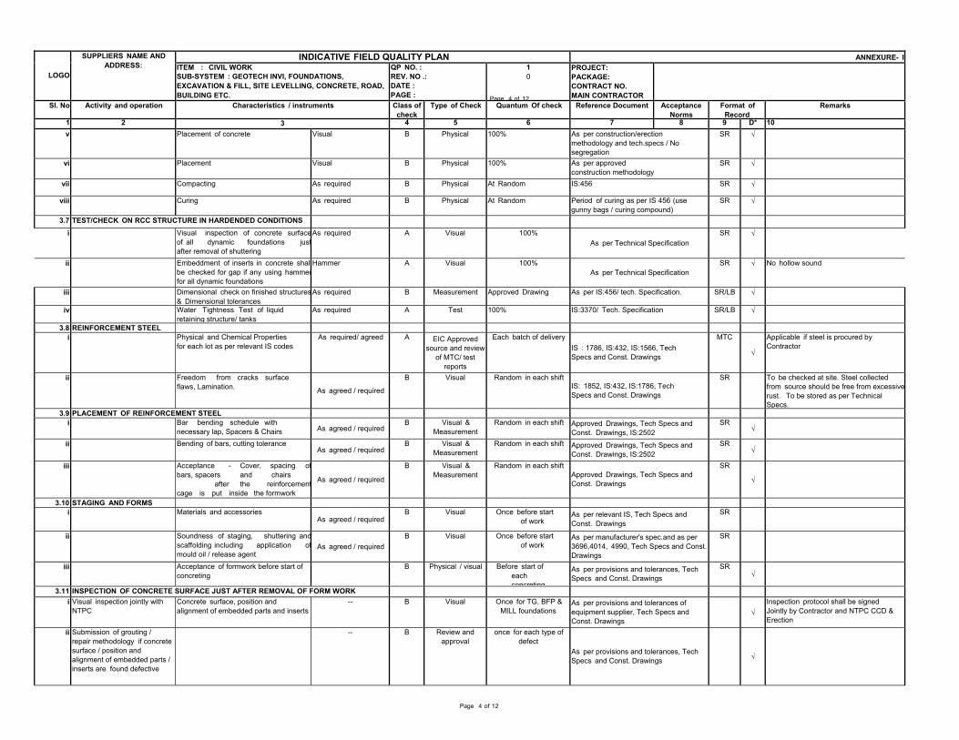
LOGO SUPPLIERS NAME AND
ADDRESS: INDICATIVE FIELD QUALITY PLAN ANNEXURE- I ITEM : CIVIL WORK SUB-SYSTEM : GEOTECH INVI, FOUNDATIONS, EXCAVATION & FILL, SITE LEVELLING, CONCRETE, ROAD, BUILDING ETC.
QP NO. :REV. NO .: DATE : PAGE :
10
Page 4 of 12
PROJECT: PACKAGE: CONTRACT NO. MAIN CONTRACTOR
Sl. No Activity and operation Characteristics / instruments Class ofcheck
Type of Check Quantum Of check Reference Document Acceptance Norms
Format of Record
Remarks
1 2 3 4 5 6 7 8 9 D* 10v Placement of concrete Visual B Physical 100% As per construction/erection
methodology and tech.specs / No segregation
SR √ vi Placement Visual B Physical 100% As per approved
construction methodology SR √ vii Compacting As required B Physical At Random IS:456 SR √
viii Curing As required B Physical At Random Period of curing as per IS 456 (use gunny bags / curing compound)
SR √ 3.7 TEST/CHECK ON RCC STRUCTURE IN HARDENDED CONDITIONS
i Visual inspection of concrete surfaceof all dynamic foundations justafter removal of shuttering
As required A Visual 100% As per Technical Specification
SR √ ii Embeddment of inserts in concrete shal
be checked for gap if any using hammerfor all dynamic foundations
Hammer A Visual 100% As per Technical Specification SR √ No hollow sound
iii Dimensional check on finished structures& Dimensional tolerances As required B Measurement Approved Drawing As per IS:456/ tech. Specification. SR/LB √
iv Water Tightness Test of liquid retaining structure/ tanks As required A Test 100% IS:3370/ Tech. Specification SR/LB √
3.8 REINFORCEMENT STEEL i Physical and Chemical Properties
for each lot as per relevant IS codes As required/ agreed A EIC Approved source and review
of MTC/ test reports
Each batch of delivery IS : 1786, IS:432, IS:1566, Tech Specs and Const. Drawings
MTC
√ Applicable if steel is procured by Contractor
ii Freedom from cracks surface flaws, Lamination. As agreed / required
B Visual Random in each shift IS: 1852, IS:432, IS:1786, Tech Specs and Const. Drawings
SR To be checked at site. Steel collected from source should be free from excessiverust. To be stored as per Technical Specs.
3.9 PLACEMENT OF REINFORCEMENT STEEL i Bar bending schedule with
necessary lap, Spacers & Chairs As agreed / requiredB Visual &
Measurement Random in each shift Approved Drawings, Tech Specs and Const. Drawings, IS:2502
SR√
ii Bending of bars, cutting tolerance As agreed / required
B Visual & Measurement Random in each shift Approved Drawings, Tech Specs and
Const. Drawings, IS:2502 SR
√ iii Acceptance - Cover, spacing of
bars, spacers and chairs after the reinforcementcage is put inside the formwork
As agreed / required
B Visual & Measurement Random in each shift
Approved Drawings, Tech Specs and Const. Drawings
SR
√
3.10 STAGING AND FORMS i Materials and accessories
As agreed / requiredB Visual Once before start
of work As per relevant IS, Tech Specs and Const. Drawings
SR ii Soundness of staging, shuttering and
scaffolding including application ofmould oil / release agent As agreed / required
B Visual Once before start of work As per manufacturer's spec.and as per
3696,4014, 4990, Tech Specs and Const. Drawings
SR iii Acceptance of formwork before start of
concreting B Physical / visual Before start of each concreting
As per provisions and tolerances, Tech Specs and Const. Drawings
SR√
3.11 INSPECTION OF CONCRETE SURFACE JUST AFTER REMOVAL OF FORM WORKi Visual inspection jointly with
NTPC Concrete surface, position and alignment of embedded parts and inserts
-- B Visual Once for TG, BFP & MILL foundations As per provisions and tolerances of
equipment supplier, Tech Specs and Const. Drawings
√ Inspection protocol shall be signed Jointly by Contractor and NTPC CCD & Erection
ii Submission of grouting / repair methodology if concrete surface / position and alignment of embedded parts / inserts are found defective
-- B Review and approval once for each type of
defect As per provisions and tolerances, Tech Specs and Const. Drawings
√
Page 4 of 12
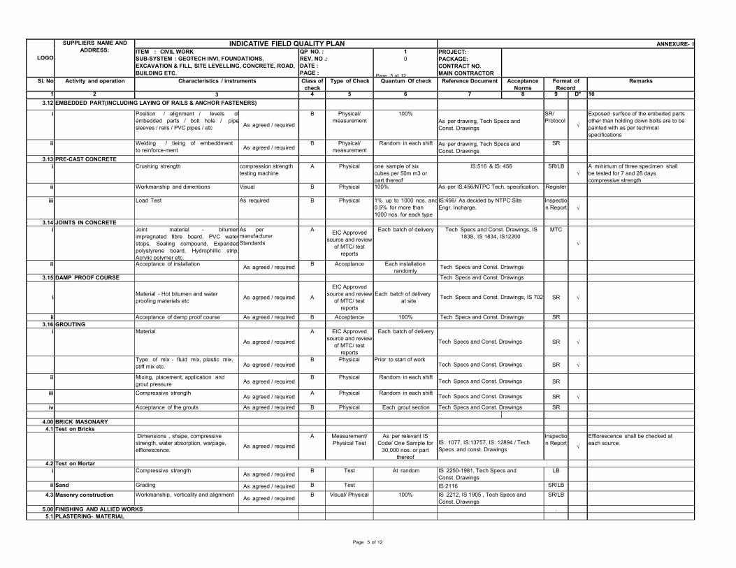
LOGO SUPPLIERS NAME AND
ADDRESS: INDICATIVE FIELD QUALITY PLAN ANNEXURE- I ITEM : CIVIL WORK SUB-SYSTEM : GEOTECH INVI, FOUNDATIONS, EXCAVATION & FILL, SITE LEVELLING, CONCRETE, ROAD, BUILDING ETC.
QP NO. :REV. NO .: DATE : PAGE :
10
Page 5 of 12
PROJECT: PACKAGE: CONTRACT NO. MAIN CONTRACTOR
Sl. No Activity and operation Characteristics / instruments Class ofcheck
Type of Check Quantum Of check Reference Document Acceptance Norms
Format of Record
Remarks
1 2 3 4 5 6 7 8 9 D* 103.12 EMBEDDED PART(INCLUDING LAYING OF RAILS & ANCHOR FASTENERS)
i Position / alignment / levels ofembedded parts / bolt hole / pipesleeves / rails / PVC pipes / etc As agreed / required
B Physical/ measurement 100%
As per drawing, Tech Specs and Const. Drawings
SR/ Protocol
√ Exposed surfsce of the embeded parts other than holding down bolts are to be painted with as per technical specifications
ii Welding / tieing of embeddment to reinforce-ment As agreed / required
B Physical/ measurement Random in each shift As per drawing, Tech Specs and
Const. DrawingsSR
3.13 PRE-CAST CONCRETE i Crushing strength compression strength
testing machine A Physical one sample of six cubes per 50m m3 or part thereof
IS:516 & IS: 456 SR/LB√ A minimum of three specimen shall
be tested for 7 and 28 days compressive strength
ii Workmanship and dimentions Visual B Physical 100% As per IS:456/NTPC Tech. specification. Register iii Load Test As required B Physical 1% up to 1000 nos. and
0.5% for more than 1000 nos. for each type
IS:456/ As decided by NTPC Site Engr. Incharge. Inspectio
n Report √ 3.14 JOINTS IN CONCRETE
i Joint material - bitumenimpregnated fibre board, PVC waterstops, Sealing compound, Expandedpolystyrene board, Hydrophillic strip,Acrylic polymer etc.
As per manufacturer Standards
A EIC Approved source and review
of MTC/ test reports
Each batch of delivery Tech Specs and Const. Drawings, IS 1838, IS 1834, IS12200 MTC
√
ii Acceptance of installation As agreed / required B Acceptance Each installation randomly
Tech Specs and Const. Drawings 3.15 DAMP PROOF COURSE Tech Specs and Const. Drawings
i
Material - Hot bitumen and water proofing materials etc As agreed / required A
EIC Approved source and review
of MTC/ test reports
Each batch of delivery at site
Tech Specs and Const. Drawings, IS 702 SR √
ii Acceptance of damp proof course As agreed / required B Acceptance 100% Tech Specs and Const. Drawings SR3.16 GROUTING
i Material As agreed / required
A EIC Approved source and review
of MTC/ test reports
Each batch of delivery Tech Specs and Const. Drawings SR √
Type of mix - fluid mix, plastic mix, stiff mix etc. As agreed / required
B Physical Prior to start of work Tech Specs and Const. Drawings SR √
ii Mixing, placement, application and grout pressure As agreed / required
B Physical Random in each shift Tech Specs and Const. Drawings SR
iii Compressive strength As agreed / required
A Physical Random in each shift Tech Specs and Const. Drawings SR √ iv Acceptance of the grouts As agreed / required B Physical Each grout section Tech Specs and Const. Drawings SR
4.00 BRICK MASONARY 4.1 Test on Bricks
Dimensions , shape, compressive strength, water absorption, warpage, efflorescence. As agreed / required
A Measurement/ Physical Test As per relevant IS
Code/ One Sample for 30,000 nos. or part
thereof
IS: 1077, IS:13757, IS: 12894 / Tech Specs and const. Drawings
Inspectio n Report √
Efflorescence shall be checked at each source.
4.2 Test on Mortar i Compressive strength
As agreed / requiredB Test At random IS 2250-1981, Tech Specs and
Const. DrawingsLB
ii Sand Grading As agreed / required B Test IS:2116 SR/LB
4.3 Masonry construction Workmanship, verticality and alignmentAs agreed / required
B Visual/ Physical 100% IS 2212, IS 1905 , Tech Specs and Const. Drawings
SR/LB 5.00 FINISHING AND ALLIED WORKS .
5.1 PLASTERING- MATERIAL
Page 5 of 12
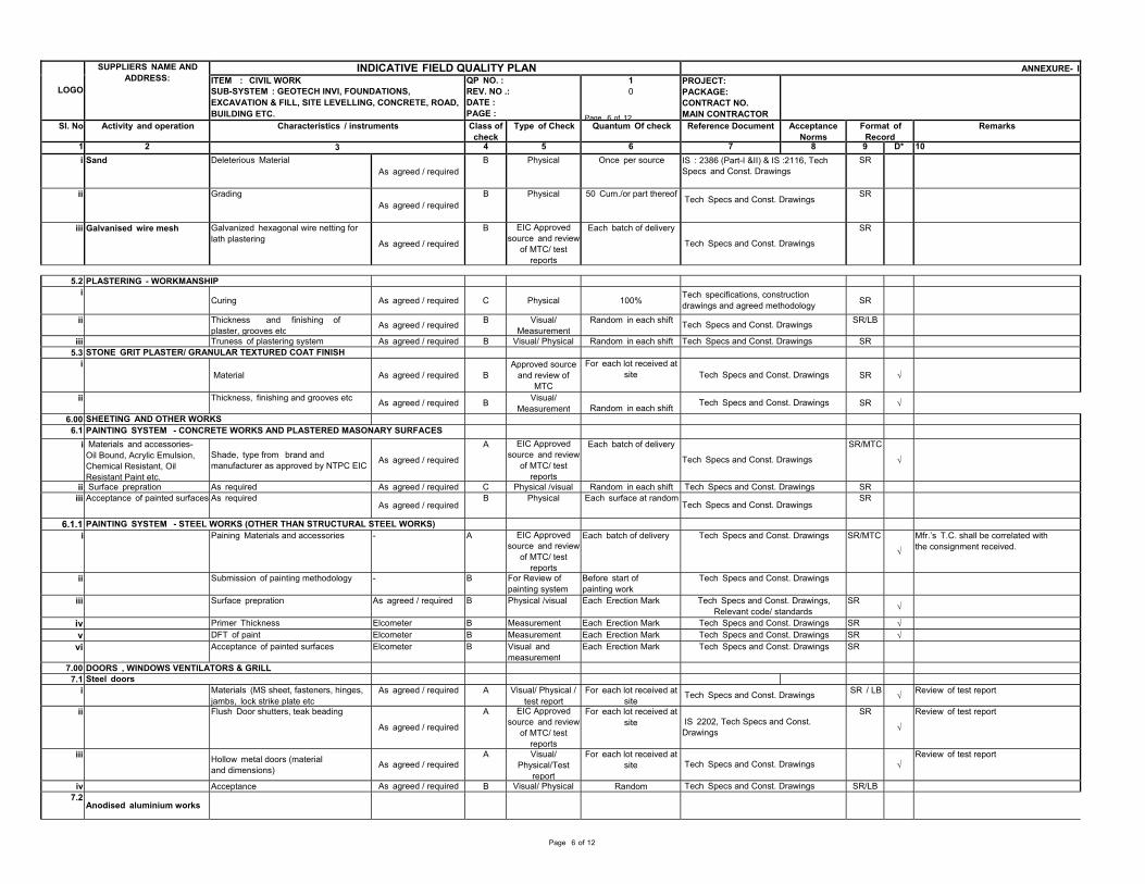
LOGO SUPPLIERS NAME AND
ADDRESS: INDICATIVE FIELD QUALITY PLAN ANNEXURE- I ITEM : CIVIL WORK SUB-SYSTEM : GEOTECH INVI, FOUNDATIONS, EXCAVATION & FILL, SITE LEVELLING, CONCRETE, ROAD, BUILDING ETC.
QP NO. :REV. NO .: DATE : PAGE :
10
Page 6 of 12
PROJECT: PACKAGE: CONTRACT NO. MAIN CONTRACTOR
Sl. No Activity and operation Characteristics / instruments Class ofcheck
Type of Check Quantum Of check Reference Document Acceptance Norms
Format of Record
Remarks
1 2 3 4 5 6 7 8 9 D* 10i Sand Deleterious Material
As agreed / requiredB Physical Once per source IS : 2386 (Part-I &II) & IS :2116, Tech
Specs and Const. Drawings SR ii Grading
As agreed / requiredB Physical 50 Cum./or part thereof
Tech Specs and Const. DrawingsSR
iii Galvanised wire mesh Galvanized hexagonal wire netting for lath plastering As agreed / required
B EIC Approvedsource and review
of MTC/ test reports
Each batch of delivery Tech Specs and Const. Drawings
SR
5.2 PLASTERING - WORKMANSHIP
i Curing As agreed / required C Physical 100% Tech specifications, construction
drawings and agreed methodology SR ii Thickness and finishing of
plaster, grooves etc As agreed / required B Visual/ Measurement
Random in each shift Tech Specs and Const. Drawings SR/LB iii Truness of plastering system As agreed / required B Visual/ Physical Random in each shift Tech Specs and Const. Drawings SR
5.3 STONE GRIT PLASTER/ GRANULAR TEXTURED COAT FINISH i
Material As agreed / required B Approved source and review of
MTC
For each lot received at site
Tech Specs and Const. Drawings SR √ ii Thickness, finishing and grooves etc As agreed / required B Visual/
Measurement Random in each shift Tech Specs and Const. Drawings SR √ 6.00 SHEETING AND OTHER WORKS
6.1 PAINTING SYSTEM - CONCRETE WORKS AND PLASTERED MASONARY SURFACESi Materials and accessories-
Oil Bound, Acrylic Emulsion, Chemical Resistant, Oil Resistant Paint etc.
Shade, type from brand and manufacturer as approved by NTPC EIC As agreed / required
A EIC Approvedsource and review
of MTC/ test reports
Each batch of delivery Tech Specs and Const. Drawings
SR/MTC
√
ii Surface prepration As required As agreed / required C Physical /visual Random in each shift Tech Specs and Const. Drawings SRiii Acceptance of painted surfaces As required
As agreed / requiredB Physical Each surface at random
Tech Specs and Const. DrawingsSR
6.1.1 PAINTING SYSTEM - STEEL WORKS (OTHER THAN STRUCTURAL STEEL WORKS)i Paining Materials and accessories - A EIC Approved
source and review of MTC/ test
reports
Each batch of delivery Tech Specs and Const. Drawings SR/MTC
√ Mfr.’s T.C. shall be correlated with the consignment received.
ii Submission of painting methodology - B For Review of painting system
Before start of painting work
Tech Specs and Const. Drawings iii Surface prepration As agreed / required B Physical /visual Each Erection Mark Tech Specs and Const. Drawings,
Relevant code/ standardsSR
√ iv Primer Thickness Elcometer B Measurement Each Erection Mark Tech Specs and Const. Drawings SR √v DFT of paint Elcometer B Measurement Each Erection Mark Tech Specs and Const. Drawings SR √vi Acceptance of painted surfaces Elcometer B Visual and
measurementEach Erection Mark Tech Specs and Const. Drawings SR
7.00 DOORS , WINDOWS VENTILATORS & GRILL 7.1 Steel doors
i Materials (MS sheet, fasteners, hinges, jambs, lock strike plate etc As agreed / required A Visual/ Physical /
test reportFor each lot received at
siteTech Specs and Const. Drawings SR / LB √ Review of test report
ii Flush Door shutters, teak beading As agreed / required
A EIC Approvedsource and review
of MTC/ test reports
For each lot received at site
IS 2202, Tech Specs and Const. Drawings
SR
√ Review of test report
iii Hollow metal doors (material and dimensions) As agreed / required
A Visual/ Physical/Test
report
For each lot received at site
Tech Specs and Const. Drawings √ Review of test report
iv Acceptance As agreed / required B Visual/ Physical Random Tech Specs and Const. Drawings SR/LB7.2
Anodised aluminium works
Page 6 of 12
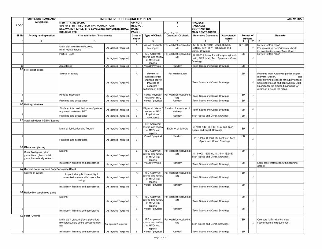
LOGO SUPPLIERS NAME AND
ADDRESS: INDICATIVE FIELD QUALITY PLAN ANNEXURE- I ITEM : CIVIL WORK SUB-SYSTEM : GEOTECH INVI, FOUNDATIONS, EXCAVATION & FILL, SITE LEVELLING, CONCRETE, ROAD, BUILDING ETC.
QP NO. :REV. NO .: DATE : PAGE :
10
Page 7 of 12
PROJECT: PACKAGE: CONTRACT NO. MAIN CONTRACTOR
Sl. No Activity and operation Characteristics / instruments Class ofcheck
Type of Check Quantum Of check Reference Document Acceptance Norms
Format of Record
Remarks
1 2 3 4 5 6 7 8 9 D* 10i Materials- Aluminium sections,
alkali resistant paint As agreed / requiredA Visual/ Physical /
test report For each lot received at site
IS: 1948, IS: 1949, IS:733, IS1285,IS:1868, IS:11857/ Tech Specs and Const. Drawings
SR / LB√ Review of test report
For aluminium door/windows, check for anodisation as per Tech. Spec
ii Particle Door As agreed / required
A EIC Approvedsource and review
of MTC/ test reports
For each lot received at site IS:12823 (phenol formaldehyde sythentic
resin, BWP type), Tech Specs and Const. Drawings
SR
√ Review of test report
iii Acceptance As agreed / required B Visual/ Physical Random Tech Specs and Const. Drawings SR7.3 Fire proof doors
i Source of supply
As agreed / required
A Review of purchase order
(unpriced copy) / drawings of suppliers /
certificate of CBRI
For each source Tech Specs and Const. Drawings
SR
√
Procured from Approved parties as per relevant IS/Tech, The door drawing proposed for supply should have been tested and approved by CBRI Roorkee for the similar dimensions for minimum 2 hours fire rating.
ii Receipt inspection As agreed / required A Visual/ Physical/ Review of MTC
For each lot received at site
Tech Specs and Const. Drawings SR √ iii Finishing and acceptance As agreed / required B Visual / physical Random Tech Specs and Const. Drawings SR
7.4 Rolling shutters i Surface finish and thickness of plate of
approved make and DFT As agreed / required A Physical / visual /review of MTC
Random for each lot of delivery
Tech Specs and Const. Drawings SR √ ii Finishing and acceptance As agreed / required B Physical and
acceptanceRandom Tech Specs and Const. Drawings SR
7.5 Steel windows / Grills/ Louvre i
Material fabrication and fixtures As agreed / required A EIC Approved
source and review of MTC/ test
reports
Each lot of delivery IS: 1038 / IS:1361, IS: 7452 and Tech Specs and Const. Drawings SR √
ii Finishing and acceptance As agreed / required B
Visual / physical Random IS: 1038 / IS:1361, IS: 7452 and Tech
Specs and Const. Drawings SR
√
7.6 Glass and glazing i Clear float glass, wired
glass, tinted glass, curtain glass, hermetically sealed glass
Material As agreed / required
B EIC Approvedsource and review
of MTC/ test reports
For each lot received at site
IS: 14900, IS:1081, IS: 3548, IS:5437 Tech Specs and Const. Drawings
SR
√
ii Installation finishing and acceptance As agreed / required B Visual/ Physical Random Tech Specs and Const. Drawings SR Leak proof installation with neoprene gasket
7.7 Curved dome on roof/ Poly Carbonate Sheet i Source of supply Impact strength, K value, light
transmission value with class -I fire rating As agreed / required
A EIC Approvedsource and review
of MTC/ test reports
For each lot received at site
Tech Specs and Const. Drawings SR
√
ii Installation finishing and acceptance As agreed / requiredB Visual / physical Random
Tech Specs and Const. DrawingsSR
7.8 Reflective toughened glass i Material
As agreed / required
A EIC Approvedsource and review
of MTC/ test reports
For each lot received at site
Tech Specs and Const. Drawings SR
√
ii Installation finishing and acceptance As agreed / requiredB Visual / physical Random
Tech Specs and Const. DrawingsSR
7.9 False Ceiling i Materials ( gypsum glass, glass fibre
membrane, fibre board acoustical tiles etc) As agreed / required
A EIC Approvedsource and review
of MTC/ test reports
For each lot received at site
Tech Specs and Const. Drawings SR
√ Compare MTC with technical specification and requirement
ii Installation finishing and acceptance As agreed / required B Visual / physical Random Tech Specs and Const. Drawings SR
Page 7 of 12
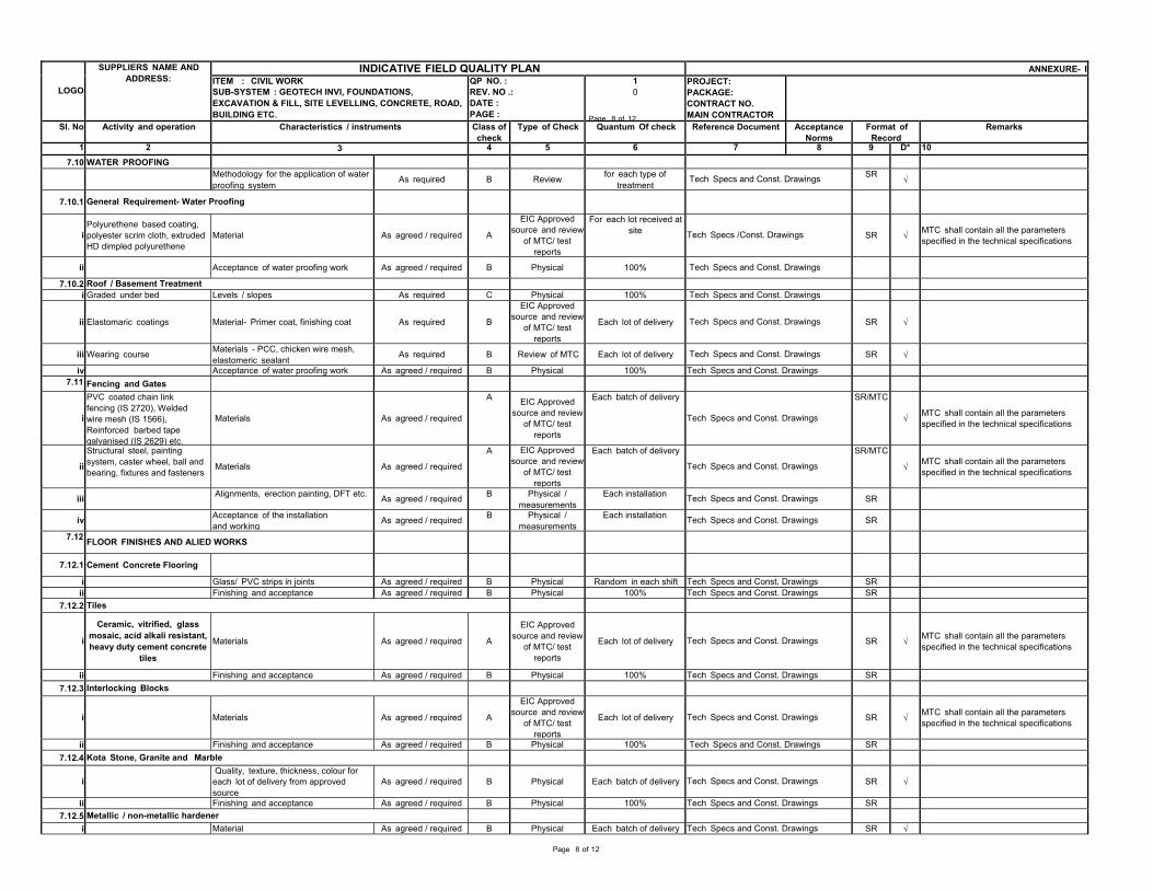
LOGO SUPPLIERS NAME AND
ADDRESS: INDICATIVE FIELD QUALITY PLAN ANNEXURE- I ITEM : CIVIL WORK SUB-SYSTEM : GEOTECH INVI, FOUNDATIONS, EXCAVATION & FILL, SITE LEVELLING, CONCRETE, ROAD, BUILDING ETC.
QP NO. :REV. NO .: DATE : PAGE :
10
Page 8 of 12
PROJECT: PACKAGE: CONTRACT NO. MAIN CONTRACTOR
Sl. No Activity and operation Characteristics / instruments Class ofcheck
Type of Check Quantum Of check Reference Document Acceptance Norms
Format of Record
Remarks
1 2 3 4 5 6 7 8 9 D* 107.10 WATER PROOFING
Methodology for the application of waterproofing system As required B Review for each type of
treatmentTech Specs and Const. Drawings SR √
7.10.1 General Requirement- Water Proofing
i Polyurethene based coating, polyester scrim cloth, extruded HD dimpled polyurethene
Material As agreed / required A
EIC Approvedsource and review
of MTC/ test reports
For each lot received at site
Tech Specs /Const. Drawings SR √ MTC shall contain all the parameters specified in the technical specifications
ii Acceptance of water proofing work As agreed / required B Physical 100% Tech Specs and Const. Drawings 7.10.2 Roof / Basement Treatment
i Graded under bed Levels / slopes As required C Physical 100% Tech Specs and Const. Drawings
ii Elastomaric coatings
Material- Primer coat, finishing coat As required B EIC Approved
source and review of MTC/ test
reports
Each lot of delivery Tech Specs and Const. Drawings SR √
iii Wearing course Materials - PCC, chicken wire mesh, elastomeric sealant As required B Review of MTC Each lot of delivery Tech Specs and Const. Drawings SR √
iv Acceptance of water proofing work As agreed / required B Physical 100% Tech Specs and Const. Drawings7.11 Fencing and Gates
i
PVC coated chain link fencing (IS 2720), Welded wire mesh (IS 1566), Reinforced barbed tape galvanised (IS 2629) etc.
Materials As agreed / required
A EIC Approved source and review
of MTC/ test reports
Each batch of delivery Tech Specs and Const. Drawings
SR/MTC
√ MTC shall contain all the parameters specified in the technical specifications
ii
Structural steel, painting system, caster wheel, ball and bearing, fixtures and fasteners
Materials As agreed / required
A EIC Approvedsource and review
of MTC/ test reports
Each batch of delivery Tech Specs and Const. Drawings
SR/MTC
√ MTC shall contain all the parameters specified in the technical specifications
iii Alignments, erection painting, DFT etc. As agreed / required B Physical / measurements
Each installation Tech Specs and Const. Drawings SR iv Acceptance of the installation
and working As agreed / required B Physical / measurements
Each installation Tech Specs and Const. Drawings SR 7.12 FLOOR FINISHES AND ALIED WORKS
7.12.1 Cement Concrete Flooring i Glass/ PVC strips in joints As agreed / required B Physical Random in each shift Tech Specs and Const. Drawings SR
ii Finishing and acceptance As agreed / required B Physical 100% Tech Specs and Const. Drawings SR7.12.2 Tiles
i Ceramic, vitrified, glass
mosaic, acid alkali resistant, heavy duty cement concrete
tiles
Materials
As agreed / required
A EIC Approved
source and review of MTC/ test
reports
Each lot of delivery Tech Specs and Const. Drawings
SR √ MTC shall contain all the parameters
specified in the technical specifications ii Finishing and acceptance As agreed / required B Physical 100% Tech Specs and Const. Drawings SR
7.12.3 Interlocking Blocks
i Materials As agreed / required A
EIC Approvedsource and review
of MTC/ test reports
Each lot of delivery Tech Specs and Const. Drawings SR √ MTC shall contain all the parameters
specified in the technical specifications ii Finishing and acceptance As agreed / required B Physical 100% Tech Specs and Const. Drawings SR
7.12.4 Kota Stone, Granite and Marble
i Quality, texture, thickness, colour for each lot of delivery from approved source As agreed / required B Physical Each batch of delivery
Tech Specs and Const. Drawings SR √ ii Finishing and acceptance As agreed / required B Physical 100% Tech Specs and Const. Drawings SR
7.12.5 Metallic / non-metallic hardener i Material As agreed / required B Physical Each batch of delivery Tech Specs and Const. Drawings SR √
Page 8 of 12
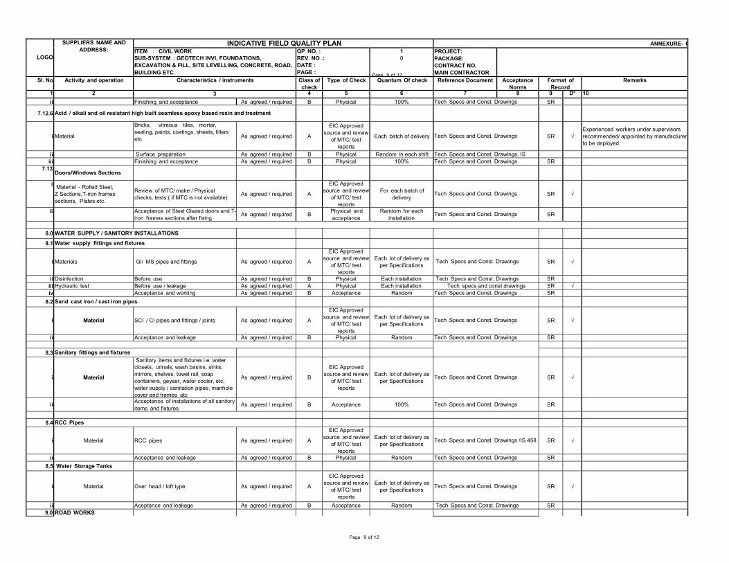
LOGO SUPPLIERS NAME AND
ADDRESS: INDICATIVE FIELD QUALITY PLAN ANNEXURE- I ITEM : CIVIL WORK SUB-SYSTEM : GEOTECH INVI, FOUNDATIONS, EXCAVATION & FILL, SITE LEVELLING, CONCRETE, ROAD, BUILDING ETC.
QP NO. :REV. NO .: DATE : PAGE :
10
Page 9 of 12
PROJECT: PACKAGE: CONTRACT NO. MAIN CONTRACTOR
Sl. No Activity and operation Characteristics / instruments Class ofcheck
Type of Check Quantum Of check Reference Document Acceptance Norms
Format of Record
Remarks
1 2 3 4 5 6 7 8 9 D* 10ii Finishing and acceptance As agreed / required B Physical 100% Tech Specs and Const. Drawings SR
7.12.6 Acid / alkali and oil resistant high built seamless epoxy based resin and treatment
i Material
Bricks, vitreous tiles, mortar, sealing, paints, coatings, sheets, fillers etc As agreed / required A
EIC Approved source and review
of MTC/ test reports
Each batch of delivery Tech Specs and Const. Drawings SR √ Experienced workers under supervisors recommended/ appointed by manufacturer to be deployed
ii Surface preparation As agreed / required B Physical Random in each shift Tech Specs and Const. Drawings, ISiii Finishing and acceptance As agreed / required B Physical 100% Tech Specs and Const. Drawings SR
7.13 Doors/Windows Sections
i Material - Rolled Steel, Z Sections,T-iron frames sections, Plates etc.
Review of MTC/ make / Physical checks, tests ( if MTC is not available) As agreed / required A
EIC Approvedsource and review
of MTC/ test reports
For each batch of delivery
Tech Specs and Const. Drawings SR √
ii Acceptance of Steel Glazed doors and T-iron frames sections after fixing As agreed / required B Physical and
acceptanceRandom for each
installationTech Specs and Const. Drawings SR
8.0 WATER SUPPLY / SANITORY INSTALLATIONS 8.1 Water supply fittings and fixtures
i Materials
GI/ MS pipes and fittings As agreed / required A EIC Approved
source and review of MTC/ test
reports
Each lot of delivery as per Specifications
Tech Specs and Const. Drawings SR √
ii Disinfection Before use As agreed / required B Physical Each installation Tech Specs and Const. Drawings SRiii Hydraulic test Before use / leakage As agreed / required A Physical Each installation Tech specs and const drawings SR √iv Acceptance and working As agreed / required B Acceptance Random Tech Specs and Const. Drawings SR
8.2 Sand cast iron / cast iron pipes
i Material SCI / CI pipes and fittings / joints As agreed / required A
EIC Approvedsource and review
of MTC/ test reports
Each lot of delivery as per Specifications
Tech Specs and Const. Drawings SR √
ii Acceptance and leakage As agreed / required B Physical Random Tech Specs and Const. Drawings SR
8.3 Sanitary fittings and fixtures
i
Material Sanitory items and fixtures i.e. water
closets, urinals, wash basins, sinks, mirrors, shelves, towel rail, soap containers, geyser, water cooler, etc, water supply / sanitation pipes, manhole cover and frames etc
As agreed / required
B
EIC Approved source and review
of MTC/ test reports
Each lot of delivery as per Specifications
Tech Specs and Const. Drawings
SR √
ii Acceptance of installations of all sanitoryitems and fixtures As agreed / required B Acceptance 100% Tech Specs and Const. Drawings SR
8.4 RCC Pipes
i Material RCC pipes As agreed / required A
EIC Approvedsource and review
of MTC/ test reports
Each lot of delivery as per Specifications
Tech Specs and Const. Drawings /IS 458 SR √
ii Acceptance and leakage As agreed / required B Physical Random Tech Specs and Const. Drawings SR8.5 Water Storage Tanks
i
Material Over head / loft type As agreed / required A
EIC Approved source and review
of MTC/ test reports
Each lot of delivery as per Specifications
Tech Specs and Const. Drawings SR √
ii Aceptance and leakage As agreed / required B Acceptance Random Tech Specs and Const. Drawings SR9.0 ROAD WORKS
Page 9 of 12
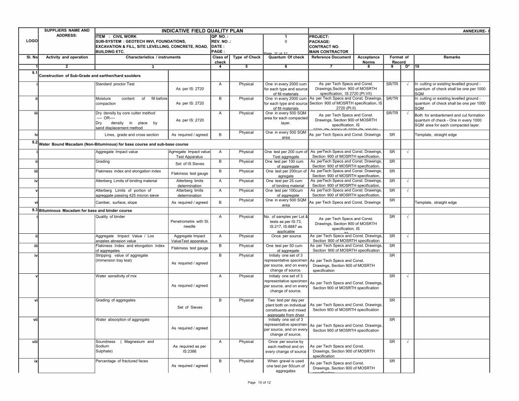
LOGO SUPPLIERS NAME AND
ADDRESS: INDICATIVE FIELD QUALITY PLAN ANNEXURE- I ITEM : CIVIL WORK SUB-SYSTEM : GEOTECH INVI, FOUNDATIONS, EXCAVATION & FILL, SITE LEVELLING, CONCRETE, ROAD, BUILDING ETC.
QP NO. :REV. NO .: DATE : PAGE :
10
Page 10 of 12
PROJECT: PACKAGE: CONTRACT NO. MAIN CONTRACTOR
Sl. No Activity and operation Characteristics / instruments Class ofcheck
Type of Check Quantum Of check Reference Document Acceptance Norms
Format of Record
Remarks
1 2 3 4 5 6 7 8 9 D* 109.1
Construction of Sub-Grade and earthen/hard soulders i Standard proctor Test
As per IS: 2720 A Physical One in every 2000 cum for each type and source
of fill materials
As per Tech Specs and Const.Drawings,Section 900 of MOSRTH
specification, IS 2720 (Pt.VII)
SR/TR √ In cutting or existing levelled ground - quantum of check shall be one per 1000 SQM
ii Moisture content of fill before compaction As per IS: 2720 B Physical One in every 2000 cum
for each type and source of fill materials
As per Tech Specs and Const. Drawings,Section 900 of MOSRTH specification, IS
2720 (Pt.II)
SR/TR In cutting or existing levelled ground - quantum of check shall be one per 1000 SQM
iii Dry density by core cutter method ---- OR----
Dry density in place by sand displacement method
As per IS: 2720 A Physical One in every 500 SQM
area for each compacted layer.
As per Tech Specs and Const. Drawings, Section 900 of MOSRTH
specification, IS 2720 (Pt XXIX)/ IS 2720 (Pt XXVIII)
SR/TR √ Both for embankment and cut formation quantum of check - One in every 1000 SQM area for each compacted layer.
iv Lines, grade and cross section As required / agreed B Physical One in every 500 SQM area
As per Tech Specs and Const. Drawings SR Template, straight edge
9.2 Water Bound Macadam (Non-Bituminous) for base course and sub-base course i Aggregate Impact value Agrregate Impact value
Test ApparatusA Physical One test per 200 cum of
Test aggregateAs perTech Specs and Const. Drawings,Section 900 of MOSRTH specification,
SR √ ii Grading Set of IS Sieves B Physical One test per 100 cum
of aggregateAs perTech Specs and Const. Drawings,Section 900 of MOSRTH specification,
SR iii Flakiness index and elongation index Flakiness test gauge B Physical One test per 200cun of
agregateAs perTech Specs and Const. Drawings,Section 900 of MOSRTH specification,
SR iv Atterberg Limits of binding material Atterberg limits
determinationA Physical One test per 25 cum
of binding material As perTech Specs and Const. Drawings,Section 900 of MOSRTH specification,
SR √ v Atterberg Limits of portion of
agreggate passing 425 micron sieve Atterberg limits determination
A Physical One test per 100cum of aggregate
As perTech Specs and Const. Drawings,Section 900 of MOSRTH specification,
SR √ vi Camber, surface, slope As required / agreed B Physical One in every 500 SQM
areaAs per Tech Specs and Const. Drawings SR Template, straight edge
9.3 Bituminous Macadam for base and binder course i Quality of binder
Penetrometre with St. needle
A Physical No. of samples per Lot & tests as per IS:73, IS:217, IS:8887 as
applicable
As per Tech Specs and Const. Drawings, Section 900 of MOSRTH
specification, IS 73
SR √
ii Aggregate Impact Value / Los angeles abrasion value Aggregate Impact
ValueTest apparatusA Physical Once per source As per Tech Specs and Const. Drawings,
Section 900 of MOSRTH specificationSR √
iii Flakiness Index and elongation index of aggregates Flakiness test gauge B Physical One test per 50 cum
of aggregateAs per Tech Specs and Const. Drawings,
Section 900 of MOSRTH specificationSR
iv Stripping value of aggregate (Immersion tray test)
As required / agreed
B Physical Initialy one set of 3 representative specimen per source, and on every
change of source.
As per Tech Specs and Const.
Drawings, Section 900 of MOSRTH specification
SR
v Water sensitivity of mix As required / agreed
A Physical Initialy one set of 3 representative specimen per source, and on every
change of source. As per Tech Specs and Const. Drawings,
Section 900 of MOSRTH specification
SR √
vi Grading of aggregates Set of Sieves
B Physical Two test per day per plant both on individual constituents and mixed aggregate from dryer
As per Tech Specs and Const. Drawings,
Section 900 of MOSRTH specification
SR
vii Water absorption of aggregate As required / agreed
Initially one set of 3 representative specimen per source, and on every
change of source.
As per Tech Specs and Const. Drawings,
Section 900 of MOSRTH specification
SR
viii Soundness ( Magnesium and Sodium Sulphate) As required as per
IS:2386 A Physical Once per source by
each method and on every change of source
As per Tech Specs and Const.
Drawings, Section 900 of MOSRTH specification
SR √
ix Percentage of fractured faces As required / agreed
B Physical When gravel is used one test per 50cum of
aggregates
As per Tech Specs and Const. Drawings, Section 900 of MOSRTH specification
SR
Page 10 of 12
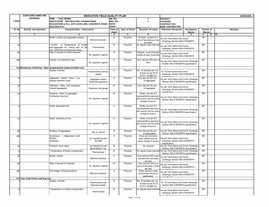
LOGO SUPPLIERS NAME AND
ADDRESS: INDICATIVE FIELD QUALITY PLAN ANNEXURE- I ITEM : CIVIL WORK SUB-SYSTEM : GEOTECH INVI, FOUNDATIONS, EXCAVATION & FILL, SITE LEVELLING, CONCRETE, ROAD, BUILDING ETC.
QP NO. :REV. NO .: DATE : PAGE :
10
Page 11 of 12
PROJECT: PACKAGE: CONTRACT NO. MAIN CONTRACTOR
Sl. No Activity and operation Characteristics / instruments Class ofcheck
Type of Check Quantum Of check Reference Document Acceptance Norms
Format of Record
Remarks
1 2 3 4 5 6 7 8 9 D* 10x Binder content and aggregate grading
Bitumen extractor A Physical Periodic, subject to a min of two tests per day
per plant
As per Tech Specs and Const. Drawings, Section 900 of MOSRTH specification
SR √ xi Control of Temperature of binder
and aggregate for mixing and of themix at the time of laying and rolling Thermometer B Physical At regular close intervals As per Tech Specs and Const.
Drawings, Section 900 of MOSRTH specification
SR xii Rate of spread of mixed materials
As required / agreedB Physical Regular control through
checks of layer thickness As per Tech Specs and Const. Drawings, Section 900 of MOSRTH specification
SR xiii Density of compacted Layer
As required / agreedA Physical One test per 250 sqm of
area As per Tech Specs and Const. Drawings, Section 900 of MOSRTH specification
SR √ 9.4 Bituminous Surfacing - Open graded premix carpet and Seal coat
i Quality of binder Penetrometre with St. needle
A Physical No. of samples per Lot & tests as per IS:73, IS:217, IS:8887 as
IS 73,Tech Specs and Const. Drawings, Section 900 of MOSRTH specification
SR √ ii Aggregate Impact Value / Los
angeles abrasion value Aggregate Impact ValueTest apparatus
A Physical One test per 50 cum of aggregate As per Tech Specs and Const. Drawings,
Section 900 of MOSRTH specification
SR √ iii Flakiness Index and elongation
indexof aggregates Flakiness test gaugeB Physical One test per 50 cum
of aggregate As per Tech Specs and Const. Drawings, Section 900 of MOSRTH specification
SR iv Stripping value of aggregate
(Immersion tray test) As required / agreed
B Physical Initialy one set of 3 representative specimen per source, and on every
change of source. As per Tech Specs and Const. Drawings,
Section 900 of MOSRTH specification
SR
v Water absorption test A Physical Initialy one set of 3 representative specimen per source, and on every
change of source. As per Tech Specs and Const. Drawings,
Section 900 of MOSRTH specification
SR √
vi Water sensitivity of mix As required / agreed
A Physical Initialy one set of 3 representative specimen per source, and on every
change of source. As per Tech Specs and Const. Drawings,
Section 900 of MOSRTH specification
SR √
vii Grading of aggregates Set of Sieves B Physical One test per 25 cum of aggregates As per Tech Specs and Const. Drawings,
Section 900 of MOSRTH specificationSR
viii Soundness ( Magnesium and Sodium Sulphate) As required as per
IS:2386 A Physical Once per source by
each method and on every change of source
As per Tech Specs and Const.
Drawings, Section 900 of MOSRTH specification
SR √
ix Polished stone value As required as per BS:812(Part 114)
B Physical As required As per Tech Specs and Const. Drawings,Section 900 of MOSRTH specification
SR x Temperature of binder at application Thermometer B Physical At regular close intervals As per Tech Specs and Const. Drawings,
Section 900 of MOSRTH specificationSR
xi Binder content Bitumen extractor A Physical One test per 500 cum&
not less than two tests per day
As per Tech Specs and Const. Drawings, Section 900 of MOSRTH specification
SR √ xii Rate of spread of materials
As required / agreedB Physical One test per 500 cum
and not less than 2 tests per day
As per Tech Specs and Const. Drawings, Section 900 of MOSRTH specification
SR xiii Percentage of fractured faces
Bitumen extractor A Physical When gravel is used one test per 50cum of
aggregates
As per Tech Specs and Const. Drawings, Section 900 of MOSRTH specification
SR √ 9.5 Tack Coat/ Prime coat/ fog coat
i Quality of binder Penetrometre with Standard needle
A Physical No. of samples per Lot & tests as per IS:73, IS:217, IS:8887 as
IS 73,Tech Specs and Const. Drawings, Section 900 of MOSRTH specification
SR √ ii Temperature of binder at application
Thermometer B Physical At regular close intervals As per Tech Specs and Const. Drawings, Section 900 of MOSRTH specification
SR Page 11 of 12
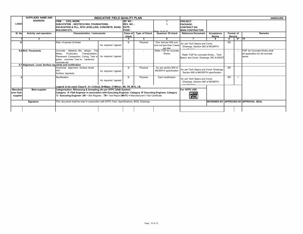
LOGO SU
Sl. No A
1 iii
9.6 RCC
9.7 Aligni
ii
Manufact urer/ Sub-
supplier S
UPPLIERS NAME AND ADDRESS: IT
SEB
Activity and operation 2
R
Pavements CMPgc
nment, Level, Surface reguHaS
R
LMain-supplier C
C‘
Signature T
TEM : CIVIL WORK SUB-SYSTEM : GEOTECH EXCAVATION & FILL, SITEBUILDING ETC.
Characteris
Rate of spread of binder
Concrete - Material, Mix dMixes, Production, TraPlacement, Compaction, Cugreen concrete, Test on hconcrete etc. ularity and rectification Horizontal alignment, Surfaand Surface regularity Rectification
Legend to be used: Class #Categorization WitnessingCategory ‘A’ FQA EngineeC’ Executing Engineer ;SR
This document shall be read
INDICATIVE F
INVI, FOUNDATIONS, LEVELLING, CONCRETE,
stics / instruments
3 As required /
design, Trialansportation, ring, Test onhardened
As required /
ce levels As required /
As required /
# : A = Critical, B=Major, C & Accepting (As per NTPCr in association with Execu
R = Site Register , TR= Test
in conjunction with NTPC T
FIELD QUALITY PLAN
ROAD,
QP NO. :REV. NO .: DATE : PAGE :Class ofcheck
Type
4
/ agreedB Ph
/ agreed
-
/ agreedB Ph
/ agreedB Ph
=Minor; SR, TR, MTC, LBC QA&I System) uting Engineer, Category ‘Report,MfrTC = Manufactur
Tech. Specifications, BOQ, D
N10
Page 12 of 12
of Check Quantum Of
5 6hysical One test per 5
and not less thaper day
- Refer FQP for Works
hysical As per sectionMOSRTH spec
hysical Each rectific
B’ Executing Engineer, Carer's Test Certificate
Drawings
Page 12 of 12
PROJECT: PACKAGE: CONTRACT NO. MAIN CONTRAC
f check Reference Docu
7500 cum an 2 tests y
As per Tech SpeDrawings, Sectispecificationconcrete
s Refer FQP for c
Specs and Const
n 900 of cification As per Tech Spe
Section 900 of M
cation As per Tech Spe
Drawings, Sectispecification
ategory For NTPC USE
CTOR
ument Acceptance Norms
8
ecs and Const. tion 900 of MOSRTH
concrete Works, , Tech t. Drawings, IRC & MOST
ecs and Const. Drawings, MOSRTH specification
ecs and Const. tion 900 of MOSRTH
REVIEWED BY AP
Format of Record
9 D* 10SR - − FQP for Con
be applicatioworks
SR SR √
PPROVED BY APPROVAL
ANNEXURE
Remarks
ncrete Works shall on for all concrete
L SEAL
- I
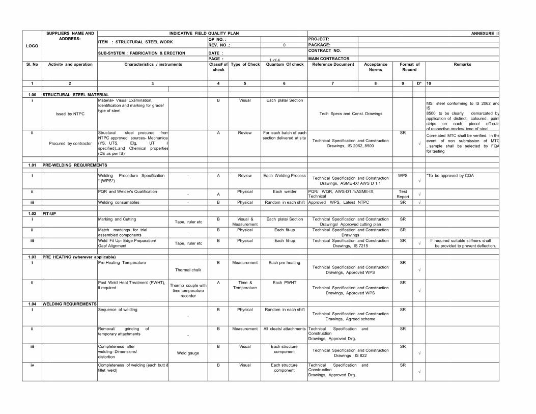
LOGO SU
Sl. No A
1 1.00 STR
i
ii
P
1.01 PRE
i ii iii
1.02 FIT-i ii iii
1.03 PREi
ii
1.04 WELi
ii
iii
iv
UPPLIERS NAME AND ADDRESS:
IT
S
Activity and operation
2 RUCTURAL STEEL MATER
Issed by NTPC
MIdty
Procured by contractor SN(Ys(C
E-WELDING REQUIREMEN
W*
P
W
-UP M
MaWG
E HEATING (wherever appP
Pif
LDING REQUIREMENTS S
Rte
Cwd
Cfi
TEM : STRUCTURAL ST
SUB-SYSTEM : FABRICAT
Characteristic
RIAL Material- Visual Examinationdentification and marking forype of steel
Structural steel procureNTPC approved sources- MYS, UTS, Elg, Upecified),,and Chemical CE as per IS) NTS Welding Procedure Spec
(WPS*) PQR and Welder's Qualifica
Welding consumables
Marking and Cutting Match markings for trial assembled components Weld Fit Up- Edge PreparatiGap/ Alignment plicable) Pre-Heating Temperature
Post Weld Heat Treatment (f required
Sequence of welding
Removal/ grinding of emporary attachments
Completeness after welding- Dimensions/
istortion Completeness of welding (eallet weld)
INDICATIVE FIE
TEEL WORK
TION & ERECTION
cs / instruments
3
n, r grade/
ed fromMechanicalUT ifproperties
cification -
tion -
-
Tape, ruler et
-
on/ Tape, ruler et
Thermal chalk
(PWHT), Thermo couple w
time temperaturecorder
-
-
Weld gauge
ach butt &
ELD QUALITY PLANQP NO. :REV. NO .:
DATE :PAGE :Class# of
checkType of C
4 5
B Visual
A Review
A Review
APhysica
B Physica
cB Visual
MeasuremB Physica
cB Physica
k B Measurem
withre
A Time &Temperat
B Physica
B Measurem
B Visual
B Visual
0
1 of 4heck Quantum Of chec
6
Each plate/ Sectio
w For each batch of easection delivered at s
w Each Welding Proce
al Each welder
al Random in each sh
& ment
Each plate/ Sectio
al Each fit-up
al Each fit-up
ment Each pre-heating
& ture
Each PWHT
al Random in each sh
ment All cleats/ attachme
Each structure component
Each structure component
PROJECT: PACKAGE: CONTRACT NO.
MAIN CONTRACTORck Reference Documen
7
on
Tech Specs and
ach site
Technical SpecificatiDrawings, IS
ess Technical SpecificatiDrawings, ASME
PQR/ WQR, AWS-D1Technical
hift Approved WPS, Late
on Technical SpecificatiDrawings/ Appro
Technical SpecificatiDraw
Technical SpecificatiDrawings,
Technical SpecificatiDrawings, Ap
Technical SpecificatiDrawings, Ap
hiftTechnical Specificati
Drawings, Ag
nts Technical SpecificatConstruction Drawings, Approved D
Technical SpecificatiDrawings
Technical SpecificatConstruction Drawings, Approved D
nt Acceptance Norms F
8
Const. Drawings
ion and Construction S 2062, 8500
S
ion and Construction E-IX/ AWS D 1.1
W
1.1/ASME-IX, TRe
est NTPC S
ion and Construction oved cutting plan
S
ion and Construction wings
S
ion and Construction , IS 7215
S
ion and Construction pproved WPS
S
ion and Construction pproved WPS
S
ion and Construction greed scheme
S
tion and
Drg. S
ion and Construction s, IS 822
S
tion and
Drg. S
Format of Record
9 D* 10
MS steel coIS 8500 to be application ofstrips on of respective
SR
√ Correlated Mevent of no, sample shafor testing
WPS√ *To be appro
Test eport √ SR √
SR SR SR
√If required
be provid
SR
√
SR
√
SR
SR
SR√
SR√
ANNEXURE II
Remarks
onforming to IS 2062 and
clearly demarcated byf distinct coloured paint each piece/ off-cuts
grades/ type of steel.TC shall be verified. In theon submission of MTCall be selected by FQA
oved by CQA
suitable stiffners shall ded to prevent deflection.
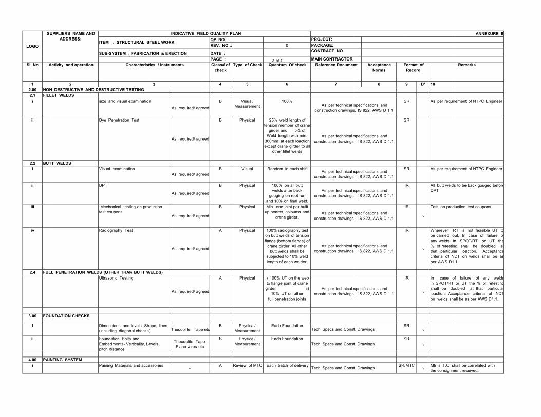
LOGO SU
Sl. No A
1 2.00 NON2.1 FILL
i
ii
2.2 BUTi ii
iii
iv
2.4 FUL
3.00 FOU
i ii
4.00 PAINi
UPPLIERS NAME AND ADDRESS:
IT
S
Activity and operation
2 N DESTRUCTIVE AND DELET WELDS
s
D
TT WELDS V
D
Mte
R
LL PENETRATION WELDSU
UNDATION CHECKS D(i
FEp
NTING SYSTEM P
TEM : STRUCTURAL ST
SUB-SYSTEM : FABRICAT
Characteristic
STRUCTIVE TESTING ize and visual examination
Dye Penetration Test
Visual examination
DPT
Mechanical testing on produest coupons
Radiography Test
S (OTHER THAN BUTT WEUltrasonic Testing
Dimensions and levels- Shancluding diagonal checks)
Foundation Bolts and Embedments- Verticality, Levpitch distance
Paining Materials and acces
INDICATIVE FIE
TEEL WORK
TION & ERECTION
cs / instruments
3
As required/ agr
As required/ agr
As required/ agr
As required/ agr
uction
As required/ agr
As required/ agr
ELDS)
As required/ agr
pe, lines Theodolite, Tape
vels, Theodolite, TapPiano wires etc
ssories -
ELD QUALITY PLANQP NO. :REV. NO .:
DATE :PAGE :Class# of
checkType of C
4 5
eed
B Visual/Measurem
eed
B Physica
eedB Visual
eed
B Physica
eed
B Physica
eed
A Physica
eed
A Physica
e etcB Physica
Measurem
pe, c
B PhysicaMeasurem
A Review of
0
2 of 4heck Quantum Of chec
6
/ ment
100%
al 25% weld length otension member of cr
girder and 5% oWeld length with mi
300mm at each loactexcept crane girder to
other fillet welds
Random in each sh
al 100% on all buttwelds after back
gouging on root runand 10% on final we
al Min. one joint per buup beams, coloums a
crane girder. al 100% radiography te
on butt welds of tensflange (bottom flange
crane girder. All othbutt welds shall be
subjected to 10% welength of each welde
al i) 100% UT on the wto flange joint of cra
girder10% UT on other
full penetration joint
al/ ment
Each Foundation
al/ ment
Each Foundation
MTC Each batch of delive
PROJECT: PACKAGE: CONTRACT NO.
MAIN CONTRACTORck Reference Documen
7
As per technical sconstruction drawings
of raneof in. tiono all
As per technical s
construction drawings
hiftAs per technical s
construction drawings
n eld.
As per technical sconstruction drawings
uilt and As per technical s
construction drawings
est sione) of er
e eld er.
As per technical s
construction drawings
web ne
ii)
ts
As per technical s
construction drawings
Tech Specs and Const
Tech Specs and Const
ery Tech Specs and Const
nt Acceptance Norms F
8
specifications and s, IS 822, AWS D 1.1
S
specifications and s, IS 822, AWS D 1.1
S
specifications and s, IS 822, AWS D 1.1
S
specifications and s, IS 822, AWS D 1.1
specifications and s, IS 822, AWS D 1.1
specifications and s, IS 822, AWS D 1.1
specifications and s, IS 822, AWS D 1.1
t. Drawings S
t. Drawings S
t. Drawings SR/
Format of Record
9 D* 10
SR As per requir
SR
SR As per requir
IR All butt weldsDPT
IR
√ Test on produ
IR
√
Wherever Rbe carried ouany welds in% of retestinthat particulacriteria of NDper AWS D1.
IR
√
In case ofin SPOT/RT shall be doloaction. Acceon welds sha
SR√
SR√
/MTC√
Mfr.’s T.C. shthe consignm
ANNEXURE II
Remarks
rement of NTPC Engineer
rement of NTPC Engineer
s to be back gouged before
uction test coupons
RT is not feasible UT tout. In case of failure ofn SPOT/RT or UT theg shall be doubled at
ar loaction. AcceptanceDT on welds shall be as1.
f failure of any weldsor UT the % of retestingubled at that particulareptance criteria of NDTall be as per AWS D1.1.
hall be correlated with ent received.
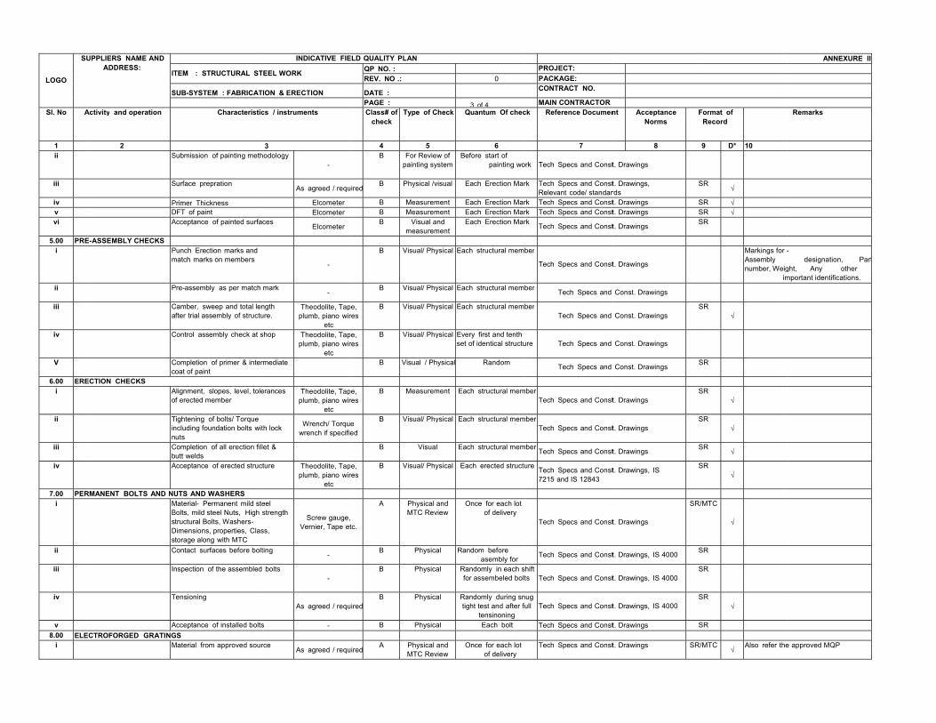
LOGO SU
Sl. No A
1 ii iii iv v vi
5.00 PREi
ii iii iv V
6.00 EREi ii iii iv
7.00 PERi
ii iii iv v
8.00 ELEi
UPPLIERS NAME AND ADDRESS:
IT
S
Activity and operation
2 S
S
PDA
E-ASSEMBLY CHECKS Pm
P
Ca
C
Cc
ECTION CHECKS Ao
TinnCbA
RMANENT BOLTS AND NUMBsDsC
In
T
AECTROFORGED GRATING
M
TEM : STRUCTURAL ST
SUB-SYSTEM : FABRICAT
Characteristic
Submission of painting meth
Surface prepration Primer Thickness DFT of paint Acceptance of painted surfa
Punch Erection marks and match marks on members
Pre-assembly as per match
Camber, sweep and total lenafter trial assembly of structu
Control assembly check at s
Completion of primer & interoat of paint
Alignment, slopes, level, toleof erected member Tightening of bolts/ Torque ncluding foundation bolts wituts
Completion of all erection fillbutt welds Acceptance of erected struc
UTS AND WASHERS Material- Permanent mild steBolts, mild steel Nuts, High tructural Bolts, Washers-
Dimensions, properties, Clastorage along with MTC
Contact surfaces before bolt
nspection of the assembled
Tensioning
Acceptance of installed boltsGS Material from approved sour
INDICATIVE FIE
TEEL WORK
TION & ERECTION
cs / instruments
3 hodology
- As agreed / requ
ElcometerElcometer
ces Elcometer
- mark
-
ngth ure. Theodolite, Tap
plumb, piano wiretc
shop Theodolite, Tapplumb, piano wir
etcrmediate erances Theodolite, Tap
plumb, piano wiretc
th lock Wrench/ Torquwrench if specifi
let & ture Theodolite, Tap
plumb, piano wiretc
eel strength
ss,
Screw gauge,Vernier, Tape et
ting -
bolts -
As agreed / requ
s -
rce As agreed / requ
ELD QUALITY PLANQP NO. :REV. NO .:
DATE :PAGE :Class# of
checkType of C
4 5B For Review
painting sy
uiredB Physical /v
B MeasuremB MeasuremB Visual a
measurem
B Visual/ Phy
B Visual/ Phy
pe, res
B Visual/ Phy
pe, res
B Visual/ Phy
B Visual / Ph
pe, res
B Measurem
e ed
B Visual/ Phy
B Visual
pe, res
B Visual/ Phy
, tc.
A Physical aMTC Rev
B Physica
B Physica
uiredB Physica
B Physica
uiredA Physical a
MTC Rev
0
3 of 4heck Quantum Of chec
6w of stem
Before start of painting wo
visual Each Erection Mar
ment Each Erection Marment Each Erection Marnd
mentEach Erection Mar
ysical Each structural mem
ysical Each structural mem
ysical Each structural mem
ysical Every first and tenth set of identical structu
ysical Random
ment Each structural mem
ysical Each structural mem
Each structural mem
ysical Each erected structu
and view
Once for each lot of delivery
al Random before asembly for
al Randomly in each sfor assembeled bolt
al Randomly during sntight test and after fu
tensinoningal Each bolt
and view
Once for each lot of delivery
PROJECT: PACKAGE: CONTRACT NO.
MAIN CONTRACTORck Reference Documen
7
ork Tech Specs and Const
rk Tech Specs and ConstRelevant code/ standar
rk Tech Specs and Constrk Tech Specs and Constrk Tech Specs and Const
ber
Tech Specs and Const
ber Tech Specs and
berTech Specs and
ure Tech Specs and
Tech Specs and
mberTech Specs and Const
mberTech Specs and Const
mber Tech Specs and Const
ure Tech Specs and Const7215 and IS 12843
Tech Specs and Const
Tech Specs and Const
hift ts Tech Specs and Const
nug ull Tech Specs and Const
Tech Specs and Const
Tech Specs and Const
nt Acceptance Norms F
8
t. Drawings t. Drawings, rds
S
t. Drawings St. Drawings S
t. Drawings S
t. Drawings
Const. Drawings Const. Drawings S
Const. Drawings
Const. Drawings S
t. Drawings S
t. Drawings S
t. Drawings S
t. Drawings, IS S
t. Drawings SR/
t. Drawings, IS 4000 S
t. Drawings, IS 4000S
t. Drawings, IS 4000S
t. Drawings S
t. Drawings SR/
Format of Record
9 D* 10
SR
√ SR √SR √SR
Markings for -Assembly number, Weig im
SR
√
SR SR
√ SR
√ SR
√ SR
√
/MTC
√
SR SR SR
√ SR
/MTC√
Also refer the
ANNEXURE II
Remarks
- designation, Part
ght, Any othermportant identifications.
e approved MQP

LOGO SUPPLIERS
NAME AND ADDRESS:
INDICATIVE FIELD QUALITY PLAN ANNEXURE II
ITEM : STRUCTURAL STEEL WORK QP NO. : PROJECT:
REV. NO .: 0 PACKAGE:
SUB-SYSTEM : FABRICATION & ERECTION
DATE : CONTRACT NO. PAGE : 4 of 4 MAIN
CONTRACTORSl. No Activity and operation Characteristics /
instruments Class# of check
Type of Check Quantum Of
check Reference Document Accept
ance Norms
Format of
Record
Remar
1 2 3 4 5 6 7 8 9 D* 10 ii Acceptance of Erection,
alignment and each Installation
As agreed / required
B Physical 1
00
Tech Specs and Const. Drawings S
R 9.00 GALVANISED STEEL HAND RAILS
i Material A Physical Once per lot Grade IS:2062, SR/L
B √ Galvanising shall be carried out as per the technical specificationsii DPT As
i dA Physica
lRandom AWS D1.1 / Technical
ifi tiSR/LB
√ LEGEND: D * Records, indentified with “Tick” (√) shall be essentially included b li i QA DOC. NO.: CS - Project Code - XXX-XX-QVC-G-002 Legend to be used: Class # : A = Critical, B=Major, C=Minor; SR, TR, MTC, LB
Manufact urer/ Sub supplier
Main-supplier Categorization Witnessing & Accepting (As per owner QA&I System)
Category ‘A’ FQA Engineer in association with Executing Engineer, Category ‘B’ Executing Engineer, Category ‘C’ Executing Engineer ;SR = Site Register , TR= Test Report,MfrTC = Manufacturer's Test Certificate
For NTPC use
Si
This document shall be read in conjunction with owner Tech. Specifications, BOQ D i
REVIEWED BY
APPROVED BY
APPROVAL SEAL
Part-B LIST OF EXHIBITS
Exhibits not shown here. Attached as per Annexure
Part-C GENERAL TECHNICAL REQUIREMENTS
GENERAL TECHNICAL REQUIREMENTS 1.0 INTRODUCTION This part covers technical requirements which will form an integral part of the Contract. The following provisions shall supplement all the detailed technical requirements brought out in the Technical Specifications and the Technical Data Sheets. 2.0 BRAND NAME Whenever a material or article is specified or described by the name of a particular brand, manufacturer or Contractor, the specific item mentioned shall be understood to be indicative of the function and quality desired, and not restrictive; other manufacturer's products may be considered provided sufficient information is furnished to enable the Employer to determine that the products proposed are equivalent to those named. 3.0 BASE OFFER & ALTERNATE PROPOSALS The Bidder's proposal shall be based upon the use of equipment and material complying fully with the requirements specified herein. It is recognized that the Contractor may have standardized on the use of certain components, materials, processes or procedures different than those specified herein. Alternate proposals offering similar equipment based on the manufacturer's standard practice may also be considered, provided the base offer is in line with technical specifications and such proposals meet the specified design standards and performance requirement and are acceptable to the Employer. Sufficient amount of information for justifying such proposals shall be furnished to Employer along with the bid to enable the Employer to determine the acceptability of these proposals. 4.0 COMPLETENESS OF FACILITIES 4.1 Bidders may note that this is a contract inclusive of the scope as indicated elsewhere in the specification. Each of the plant shall be engineered and designed in accordance with the specification requirement. All engineering and associated services are required to ensure that a completely engineered plant is provided. 4.2 All equipment furnished and works done by the Contractor shall be complete in every respect, with all mountings, fittings, fixtures and standard accessories normally provided with such equipment and/or those needed for erection, completion and safe operation & maintenance of the equipment and for the safety of the operating personnel, as required by applicable codes, though they may not have been specifically detailed in the respective specifications, unless included in the list of exclusions. All similar standard components/ parts of similar standard equipment provided shall be interchangeable with one another. 5.0 CODES & STANDARDS 5.1 In addition to the codes and standards specifically mentioned in the relevant technical specifications for the equipment / plant / system, all equipment parts, systems and works covered under this specification shall comply with all currently applicable statutory regulations and safety codes of the Republic of India as well as of the locality where they will be installed, including the following: (a.) Bureau of Indian Standards (BIS)
(b.) Indian electricity act
(c.) Indian electricity rules
(d.) Indian Explosives Act
(e.) Indian Factories Act and State Factories Act
(f.) Indian Boiler Regulations (IBR)

(g.) Regulations of the Central Pollution Control Board, India
(h.) Regulations of the Ministry of Environment & Forest (MoEF), Government of India
(i.) Pollution Control Regulations of Department of Environment, Government of India
(j.) State Pollution Control Board.
(k.) Rules for Electrical installation by Tariff Advisory Committee (TAC).
(l.) Any other statutory codes / standards / regulations, as may be applicable.
5.2 Unless covered otherwise by Indian codes & standards and in case nothing to the contrary is specifically mentioned elsewhere in the specifications, the latest editions (as applicable as on date of bid opening), of the codes and standards given below shall also apply: (a.) Japanese Industrial Standards (JIS)
(b.) American National Standards Institute (ANSI)
(c.) American Society of Testing and Materials (ASTM)
(d.) American Society of Mechanical Engineers (ASME)
(e.) American Petroleum Institute (API)
(f.) Standards of the Hydraulic Institute, U.S.A.
(g.) International Organization for Standardization (ISO)
(h.) Tubular Exchanger Manufacturer's Association (TEMA)
(i.) American Welding Society (AWS)
(j.) National Electrical Manufacturers Association (NEMA)
(k.) National Fire Protection Association (NFPA)
(l.) International Electro-Technical Commission (IEC)
(m.) Expansion Joint Manufacturers Association (EJMA)
(n.) Heat Exchange Institute (HEI)
5.3 Other International/ National standards such as DIN, VDI, BS, GOST etc. shall also be accepted for only material codes and manufacturing standards, subject to the Employer's approval, for which the Bidder shall furnish, along with the offer, adequate information to justify that these standards are equivalent or superior to the standards mentioned above. In all such cases the Bidder shall furnish specifically the variations and deviations from the standards mentioned elsewhere in the specification together with the complete word to word translation of the standard that is normally not published in English. 5.4 As regards highly standardized equipment such as Steam Turbine and Generator, National /International standards such as JIS, DIN, VDI, ISO, SEL, SEW, VDE, IEC & VGB shall also be considered as far as applicable for Design, Manufacturing and Testing of the respective equipment. In addition, these standards shall be referred for the design of machine foundations, wherever specifically mentioned in the specifications. However, for those of the above equipment not covered by these National / International standards, established and proven standards of manufacturers shall also be considered. 5.5 In the event of any conflict between the codes and standards referred to in the above clauses and the requirement of this specification, the requirement of Technical Specification shall govern. 5.6 Two (2) English language copies of all-national and international codes and/or standards which are not available with NTPC and same is used in the design of the plant, equipment, civil and structural works shall be provided by the Contractor to the Employer within two calendar months from the date of the Notification of Award.
5.7 In case of any change in codes, standards & regulations between the date of bid opening and the date when Contractors proceed with fabrication, the Employer shall have the option to incorporate the changed requirements or to retain the original standard. It shall be the responsibility of the Contractor to bring to the notice of the Employer such changes and advise Employer of the resulting effect. 6.0 EQUIPMENT FUNCTIONAL GUARANTEE The functional guarantees of the equipment under the scope of the Contract is given elsewhere in the technical specification. 7.0 DESIGN OF FACILITIES/ MAINTENANCE & AVAILABILITY CONSIDERATIONS 7.1 Design of Facilities All the design procedures, systems and components proposed shall have already been adequately developed and shall have demonstrated good reliability under similar conditions elsewhere. The Contractor shall be responsible for the selection and design of appropriate equipment to provide the best coordinated performance of the entire system. The basic requirements are detailed out in various clauses of the Technical Specifications. The design of various components, assemblies and subassemblies shall be done so that it facilitates easy field assembly and dismantling. All the rotating components shall be so selected that the natural frequency of the complete unit is not critical or close to the operating range of the unit. 7.2 Maintenance and Availability Considerations Equipment/facilities offered shall be designed for high availability, low maintenance and ease of maintenance. The Bidder shall specifically state the design features incorporated to achieve high degree of reliability/ availability and ease of maintenance. The Bidder shall also furnish details of availability records in the reference plants stated in his experience list. Bidder shall state in his offer the various maintenance intervals, spare parts and man-hour requirement during such operation. The intervals for each type of maintenance namely the minor and major overhauls shall be specified in terms of fired hours, clearly defining the spare parts and man- hour requirement for each stage. Lifting devices i.e. hoists and chain pulley jacks, etc. shall be provided by the contractor for handling of any equipment or any of its part having weight in excess of 500 kgs during erection and maintenance activities. Lifting devices like lifting tackles, slings, etc. to be connected to hook of the hoist / crane shall be provided by the contractor for lifting the equipment and accessories covered under the specification. 8.0 DOCUMENTS, DATA AND DRAWINGS TO BE FURNISHED BY CONTRACTOR 8.1 Bidders may note that this is a contract inclusive of the scope as indicated elsewhere in the specification. Each of the plant and equipment shall be fully integrated, engineered and designed to perform in accordance with the technical specification. All engineering and technical services required ensuring a completely engineered plant shall be provided in respect of mechanical, electrical, control & instrumentation, civil & structural works as per the scope. 8.2 The Contractor shall furnish engineering data/drgs. for entire equipment covered under this specification in accordance with the schedule of information as specified in Technical Specification and Data sheets.. This documentation shall include but not be limited to the following: 8.2.1 INSTRUCTION MANUALS The Contractor shall submit to the Employer, draft Instruction Manuals for all the equipment covered under the Contract by the end of one year from the date of his acceptance of the Letter of Award. The Instruction manuals shall contain full details required for erection, commissioning, operation and maintenance of each equipment. The manual shall be specifically compiled for this project. After finalization and approval of the Employer the Instruction Manuals shall be submitted. The Contract

shall not be considered to be completed for purposes of taking over until the final Instructions manuals have been supplied to the Employer. The Instruction Manuals shall comprise of the following. (a.) Erection & Commissioning Manuals/Checklists The erection & Commissioning Manuals/Checklists shall be submitted at least three (3) months prior to the commencement of erection activities of particular equipment/system. The erection manual should contain the following as a minimum. a) Erection strategy. b) Sequence of erection. c) Erection instructions. d) Critical checks and permissible deviation/tolerances. e) List of tool, tackles, heavy equipment like cranes, dozers, etc. f) Bill of Materials g) Procedure for erection. h) General safety procedures to followed during erection/installation. i) Procedure for initial checking after erection. j) Procedure for testing and acceptance norms. k) Procedure / Check list for pre-commissioning activities. l) Procedure / Check list for commissioning of the system. m) Safety precautions to be followed in electrical supply distribution during erection (b.) Operation & Maintenance Manuals i) The operating and maintenance instructions together with drawings (other than shop drawings) of the equipment, as completed, shall be in sufficient detail to enable the Employer to operate, maintain, dismantle, reassemble and adjust all parts of the equipment. They shall give a step by step procedure for all operations likely to be carried out during the life of the plant / equipment including, operation, maintenance, dismantling and repair including periodical activities such as chemical cleaning of the generator. Each manual shall also include a complete set of drawings together with performance/rating curves of the equipment and test certificates wherever applicable. The contract shall not be considered to be completed for purposes for taking over until these manuals have been supplied to the Employer. ii) If after the commissioning and initial operation of the plant, the manuals require any modification / additions / changes, the same shall be incorporated and the updated final instruction manuals shall be submitted to the Employer for records. iii) A separate section of the manual shall be for each size/ type of equipment and shall contain a detailed description of construction and operation, together with all relevant pamphlets and drawings. iv) The manuals shall include the following: a) List of spare parts along with their drawing and catalogues and procedure for ordering spares. b) Lubrication Schedule including charts showing lubrication checking, testing and replacement procedure to be carried daily, weekly, monthly & at longer intervals to ensure trouble free operation. c) Where applicable, fault location charts shall be included to facilitate finding the cause of maloperation or break down. v) Detailed specifications for all the consumables including lubricant oils, greases, and chemicals etc. system/equipment/assembly/subassembly - wise required for the complete plant. vi)On completion of erection, a complete list of bearings / equipment giving their location, and identification marks etc. shall also be furnished to the Employer indicating lubrication method for each type/category of bearing. 8.2.2 Project Completion Report The Contractor shall submit a Project Completion Report at the time of handing over the plant. After final acceptance of individual equipment /system by BHEL the Contractor will update all original drawings and documents for the equipment/ system to "as built" conditions and submit. 8.3 ENGINEERING INFORMATION SUBMISSION SCHEDULE

Prior to the award of Contract, a Detailed Engineering Information Submission Schedule shall be tied up with the Employer. For this, the bidder shall furnish a detailed list of engineering information along with the proposed submission schedule. This list would be a comprehensive one including all engineering data / drawings / information for all bought out items and manufactured items. The information shall be categorised into the following parts. (a.) Information that shall be submitted for the approval of the Employer before proceeding further, and (b.) Information that would be submitted for Employer’s information only. The Engineering Information Schedule shall be updated month-wise. The schedule should allow adequate time for proper review and incorporation of changes/ modifications, if any, to meet the contract without affecting the equipment delivery schedule and overall project schedule. The early submission of drawings and data is as important as the manufacture and delivery of equipment and hardware and this shall be duly considered while determining the overall performance and progress. 8.4 ENGINEERING PROGRESS AND EXCEPTION REPORT 8.4.1 Report giving the status of each engineering information including (a.) A list of drawings/engineering information which remains unapproved for more than four (4) weeks after the date of first submission (b.) Drawings which were not submitted as per agreed schedule. 8.4.2 The draft format for this report shall be furnished to the Employer within four (4) weeks of the award of the contract, which shall then be discussed and finalised with the Employer. 8.5 TECHNICAL CO-ORDINATION MEETING The Contractor shall organize and attend at least one monthly progress Meetings with the Employer/Employer's representatives during the period of Contract at mutually agreed venues for review of progress & resolving technical clarifications, if any. The Contractor shall attend such meetings at his own cost and fully co-operate with such persons and agencies involved during the discussions. The Contractor shall ensure availability of the concerned experts / consultants/ personnel who are empowered to take necessary decisions during these meetings. The Contractor shall be equipped with necessary tools and facilities so that, if required, the drawings/documents can be resubmitted after incorporating necessary changes and approved during the meeting itself. The Contractor shall furnish monthly progress report to the Employer detailing out the progress achieved on all erection activities as compared to the schedules. This shall be supplemented by printed colour photographs and video in VCD/DVD indicating various stages of erection and the progress of the work done at Site. The report shall also indicate the reasons for the variance between the scheduled and actual progress and the action proposed for corrective measures, wherever necessary. 8.6 DESIGN IMPROVEMENTS The Employer or the Contractor may propose changes in the specification of the equipment or quality thereof and if the parties agree upon any such changes the specification shall be modified accordingly. If any such agreed upon change is such that it affects the price and schedule of completion, the parties shall agree in writing as to the extent of any changing the price and/or schedule of completion before the Contractor proceeds with the change. Following such agreement, the provision thereof, shall be deemed to have been amended accordingly. 8.7 EQUIPMENT BASES A cast iron or welded steel base plate shall be provided for all rotating equipment which is to be installed on a concrete base, unless otherwise specifically agreed to by the Employer. Each base plate which support the unit and its drive assembly, shall be of a neat design with pads for anchoring the units, shall have a raised lip all around, and shall have threaded drain connections. 8.8 PROTECTIVE GUARDS

Suitable guards shall be provided for protection of personnel on all exposed rotating and/or moving machine parts. All such guards shall be designed for easy installation and removal for maintenance purpose. 8.9 LUBRICANTS, SERVO FLUIDS AND CHEMICALS (WHERE EVER APPLICABLE) The Bidder’s scope includes all the first fill and one year’s topping, requirements of consumables such as oils, lubricants including grease, servo fluids, gases and essential chemicals etc. Consumption of all these consumables during the initial operation and final filling after the initial operation shall also be included in the scope of the Bidder. 8.9.1 As far as possible lubricants marketed by reputed companies shall be used. The variety of lubricants shall be kept to a minimum possible. Detailed specifications for the lubricating oil, grease, gases, servo fluids, control fluids, chemicals etc. required for the complete plant covered herein shall be furnished. On completion of erection, a complete list of bearings/ equipment giving their location and identification marks shall be furnished to the Employer alongwith lubrication requirements. 8.9.2 Lubrication Equipment shall be lubricated by systems designed for continuous operation. Lubricant level indicators shall be furnished and marked to indicate proper levels under both standstill and operating conditions. 8.10 Material of Construction All materials used for the construction of the equipment shall be new and shall be in accordance with the requirements of this specification. Materials utilised for various components shall be those which have established themselves for use in such applications. 8.11 RATING PLATES, NAME PLATES & LABELS 8.11.1 Each main and auxiliary item of plant including instruments shall have permanently attached to it in a conspicuous position, a rating plate of noncorrosive material upon which shall be engraved manufacturer’s name, equipment, type or serial number together with details of the ratings, service conditions under which the item of plant in question has been designed to operate, and such diagram plates as may be required by the Employer. 8.11.2 Such nameplates or labels shall be of white non-hygroscopic material with engraved black lettering or alternately, in the case of indoor circuit breakers, starters, etc. of transparent plastic material with suitably coloured lettering engraved on the back. The name plates shall be suitably fixed on both front and rear sides. 8.11.3 Hanger/ support numbers shall be marked on all pipe supports, anchors, hangers, snubbers and restraint assemblies. Each constant and variable spring support shall also have stamped upon it the designed hot and cold load which it is intended to support. Suitable scale shall also be provided to indicate load on support/hanger. 8.11.4 Nameplates shall be as per best practices of the industry 8.11.5 All such plates, instruction plates, etc. shall be bilingual with Hindi inscription first, followed by English. Alternatively, two separate plates one with Hindi and the other with English inscriptions may be provided. 8.11.6 All segregated phases of conductors or bus ducts, indoor or outdoor, shall be provided with coloured phase plates to clearly identify the phase of the system 8.12 TOOLS AND TACKLES The Contractor shall supply with the equipment one complete set of all special tools and tackles and other instruments required for the erection, assembly, disassembly and proper maintenance of the plant and equipment and systems (including software). These special tools will also include special material handling equipment, jigs and fixtures for maintenance and calibration / readjustment, checking and measurement aids etc. A list of such tools and tackles shall be submitted by the Bidder alongwith the offer. The price of each tool / tackle shall be deemed to have been included in the total bid price. These tools and tackles shall be separately packed and sent to site. The Contractor shall also ensure that
these tools and tackles are not used by him during erection, commissioning and initial tackles. All the tools and tackles shall be of reputed make acceptable to the Employer. 8.13 Welding If the manufacturer has special requirements relating to the welding procedures for welds at the terminals of the equipment to be per formed by others the requirements shall be submitted to the Employer in advance of commencement of erection work. 8.14 COLOUR CODE FOR ALL EQUIPMENTS/ PIPINGS/ PIPE SERVICES All equipment/ piping/ pipe services are to be painted by the Contractor in accordance with Employer’s standard colour coding scheme, which will be furnished to the Contractor during detailed engineering stage. 8.15 PROTECTION AND PRESERVATIVE SHOP COATING 8.16 PROTECTION All coated surfaces shall be protected against abrasion, impact, discoloration and any other damages. All exposed threaded portions shall be suitably protected with either metallic or a non-metallic protection device. All ends of all valves and pipings and conduit equipment connections shall be properly sealed with suitable devices to protect them from damage. The parts which are likely to get rusted, due to exposure to weather, should also be properly treated and protected in a suitable manner. All primers/paints/coatings shall take into account the hot humid, corrosive & alkaline, subsoil or over ground environment as the case may be. 8.17 Preservative Shop Coating All exposed metallic surfaces subject to corrosion shall be protected by shop application of suitable coatings. All surfaces which will not be easily accessible after the shop assembly, shall be treated beforehand and protected for the life of the equipment. All surfaces shall be thoroughly cleaned of all mill scales, oxides and other coatings and prepared in the shop. The surfaces that are to be finish-painted after installation or require corrosion protection until installation, shall be shop painted with at least two coats of primer. Transformers and other electrical equipment if included shall be shop finished with one or more coats of primer and two coats of high grade resistance enamel. The finished colours shall be as per manufacturer’s standards, to be selected and specified by the Employer at a later date. Shop primer for all steel surfaces which will be exposed to operating temperature below 95 degrees Celsius shall be selected by the Contractor after obtaining specific approval of the Employer regarding the quality of primer proposed to be applied. Special high temperature primer shall be used on surfaces exposed to temperature higher than 95 degrees Celsius and such primer shall also be subject to the approval of the Employer. All other steel surfaces which are not to be painted shall be coated with suitable rust preventive compound subject to the approval of the Employer. All piping shall be cleaned after shop assembly by shot blasting or other means approved by the Employer. Lube oil piping or carbon steel shall be pickled. Painting for Civil structures shall be done as per relevant part of technical specification. 9.0 QUALITY ASSURANCE PROGRAMME 9.1 The Contractor shall adopt suitable quality assurance programme to ensure that the equipment and services under the scope of contract whether manufactured or performed within the Contractor’s works or at his sub-contractor’s premises or at the Employer’s site or at any other place of work are in accordance with the specifications. Such programmes shall be outlined by the Contractor and shall be finally accepted by the Employer/authorised representative after discussions before the award of the contract. The QA programme shall be generally in line with IS/ISO-9001.A quality assurance programme of the contractor shall generally cover the following: 9.2 (a) His organisation structure for the management and implementation of the proposed quality
assurance programme

(b) Quality System Manual
(c) Design Control System
(d) Documentation and Data Control System
(e) Qualification data for bidder’s key personnel.
(f) The procedure for purchase of materials, parts, components and selection of sub-contractor’s
services including Contractor analysis, source inspection, incoming raw-material inspection,
verification of materials purchased etc.
(g) System for shop manufacturing and site erection controls including process, fabrication and
assembly.
(h) Control of non-conforming items and system for corrective actions and resolution of deviations.
(i) Inspection and test procedure both for manufacture and field activities.
(j) Control of calibration and testing of measuring testing equipment.
(k) System for Quality Audits.
(l) System for identification and appraisal of inspection status.
(m) System for authorising release of manufactured product to the Employer.
(n) System for handling, storage and delivery.
(o) System for maintenance of records, and
(p) Quality plans for manufacturing and field activities detailing out the specific quality control procedure adopted for controlling the quality characteristics relevant to each item of equipment/component. 9.3 GENERAL REQUIREMENTS - QUALITY ASSURANCE (IF ONLY APPLICABLE) 9.3.1 All materials, components and equipment covered under this specification shall be procured, manufactured, erected, commissioned and tested at all the stages, as per a comprehensive Quality Assurance Programme. An indicative programme of inspection/tests to be carried out by the contractor for some of the major items is given in the respective technical specification. This is, however, not intended to form a comprehensive programme as it is the contractor’s responsibility to draw up and implement such programme duly approved by the Employer. The detailed Quality Plans for manufacturing and field activities shall be drawn up by the Bidder and will be submitted to Employer for approval. Schedule of finalisation of such quality plans will be finalised before award on enclosed format No. QS-01-QAI-P-01/F3. Monthly progress reports on MQP/FQP submission/approval shall be furnished on enclosed format No. QS-01-QAI-P-02/F1 9.3.2 Manufacturing Quality Plan will detail out for all the components and equipment, various tests/inspection, to be carried out as per the requirements of this specification and standards mentioned therein and quality practices and procedures followed by Contractor’s/ Subcontractor’s/ sub-supplier's Quality Control Organisation, the relevant reference documents and standards, acceptance norms, inspection documents raised etc., during all stages of materials procurement, manufacture, assembly and final testing/performance testing. The Quality Plan shall be submitted on electronic media e.g. floppy or E-mail in addition to hard copy, for review and approval. After approval the same shall be submitted in compiled form on CD-ROM. 9.3.3 Field Quality Plans will detail out for all the equipment, the quality practices and procedures etc. to be followed by the Contractor’s "Site Quality Control Organisation", during various stages of site activities starting from receipt of materials/equipment at site. 9.3.4 The Bidder shall also furnish copies of the reference documents/plant standards/acceptance norms/tests and inspection procedure etc., as referred in Quality Plans along with Quality Plans. These Quality Plans and reference documents/standards etc. will be subject to Employer’s approval

without which manufacturer shall not proceed. These approved documents shall form a part of the contract. In these approved Quality Plans, Employer shall identify customer hold points (CHP), i.e. test/checks which shall be carried out in presence of the Employer’s Project Manager or his authorised representative and beyond which the work will not proceed without consent of Employer in writing. All deviations to this specification, approved quality plans and applicable standards must be documented and referred to Employer along with technical justification for approval and dispositioning. 9.3.5 No material shall be dispatched from the manufacturer’s works before the same is accepted, subsequent to predispatch final inspection including verification of records of all previous tests/inspections by Employer’s Project Manager/Authorised representative and duly authorised for dispatch by issuance of Material Despatch Clearance Certificate (MDCC). 9.3.6 All material used for equipment manufacture including casting and forging etc. shall be of tested quality as per relevant codes/standards. Details of results of the tests conducted to determine the mechanical properties; chemical analysis and details of heat treatment procedure recommended and actually followed shall be recorded on certificates and time temperature chart. Tests shall be carried out as per applicable material standards and/or agreed details. 9.3.7 The contractor shall submit to the Employer Field Welding Schedule for field welding activities in the enclosed format No.: QS-01-CQA-W-11/F1. The field welding schedule shall be submitted to the Employer along with all supporting documents, like welding procedures, heat treatment procedures, NDT procedures etc. at least ninety days before schedule start of erection work at site. 9.3.8 All welding and brazing shall be carried out as per procedure drawn and qualified in accordance with requirements of ASME Section IX/BS-4870 or other International equivalent standard acceptable to the Employer. All welding/brazing procedures shall be submitted to the Employer or its authorised representative for approval prior to carrying out the welding/brazing. 9.3.9 All brazers, welders and welding operators employed on any part of the contract either in Contractor’s/ sub-contractor’s works or at site or elsewhere shall be qualified as per ASME Section-IX or BS-4871 or other equivalent International Standards acceptable to the Employer. 9.3.10 Welding procedure qualification & Welder qualification test results shall be furnished to the Employer for approval. However, where required by the Employer, tests shall be conducted in presence of Employer/authorised representative. 9.3.11 For all pressure parts and high pressure piping welding, the latest applicable requirements of the IBR (Indian Boiler Regulations) shall also be essentially complied with. Similarly, any other statutory requirements for the equipment/systems shall also be complied with. On all back-gauged welds MPI/LPI shall be carried before seal welding. 9.3.12 Unless otherwise proven and specifically agreed with the Employer, welding of dissimilar materials and high alloy materials shall be carried out at shop only. 9.3.13 No welding shall be carried out on cast iron components for repair. 9.3.14 All the heat treatment results shall be recorded on time temperature charts and verified with recommended regimes. 9.3.15 All non-destructive examination shall be performed in accordance with written procedures as per International Standards, The NDT operator shall be qualified as per SNT-TC-IA (of the American Society of non-destructive examination). NDT shall be recorded in a report, which includes details of methods and equipment used, result/evaluation, job data and identification of personnel employed and details of co-relation of the test report with the job. All plates of thickness above 40mm & all bar stock/Forging above 40mm dia shall be ultrasonically tested. For pressure parts, plate of thickness equal to or above 25mm shall be ultrasonically tested. 9.3.16 The Contractor shall list out all major items/ equipment/ components to be manufactured in house as well as procured from sub-contractors (BOI). All the sub-contractor proposed by the Contractor for procurement of major bought out items including castings, forging, semi-finished and finished components/equipment etc., list of which shall be drawn up by the Contractor and finalised with the Employer, shall be subject to Employer's
approval on enclosed format No. QS-01-QAI-P-01/F3. The contractor’s proposal shall include Contractor’s facilities established at the respective works, the process capability, process stabilization, QC systems followed, experience list, etc. along with his own technical evaluation for identified sub-contractors enclosed and shall be submitted to the Employer for approval within the period agreed at the time of pre awards discussion and identified in "DR" category prior to any procurement. Monthly progress reports on sub-contractor detail submission / approval shall be furnished on enclosed on format no. QS- 01-QAI-P-02/F2. Such Contractor approval shall not relieve the contractor from any obligation, duty or responsibility under the contract. 9.3.17 For components/equipment procured by the contractors for the purpose of the contract, after obtaining the written approval of the Employer, the contractor’s purchase specifications and inquiries shall call for quality plans to be submitted by the suppliers. The quality plans called for from the sub-contractor shall set out, during the various stages of manufacture and installation, the quality practices and procedures followed by the Contractor’s quality control organisation, the relevant reference documents/standards used, acceptance level, inspection of documentation raised, etc. Such quality plans of the successful Contractors shall be finalised with the Employer and such approved Quality Plans shall form a part of the purchase order/contract between the Contractor and sub-contractor. Within three weeks of the release of the purchase orders /contracts for such bought out items /components, a copy of the same without price details but together with the detailed purchase specifications, quality plans and delivery conditions shall be furnished to the Employer on the monthly basis by the Contractor along with a report of the Purchase Order placed so far for the contract. ** 9.3.18 Employer reserves the right to carry out quality audit and quality surveillance of the systems and procedures of the Contractor’s or their sub-contractor’s quality management and control activities. The contractor shall provide all necessary assistance to enable the Employer carry out such audit and surveillance. 9.3.19 The contractor shall carry out an inspection and testing programme during manufacture in his work and that of his sub-contractor’s and at site to ensure the mechanical accuracy of components, compliance with drawings, conformance to functional and performance requirements, identity and acceptability of all materials parts and equipment. Contractor shall carry out all tests/inspection required to establish that the items/equipment conform to requirements of the specification and the relevant codes/standards specified in the specification, in addition to carrying out tests as per the approved quality plan. 9.3.20 Quality audit/surveillance/approval of the results of the tests and inspection will not, however, prejudice the right of the Employer to reject he equipment if it does not comply with the specification when erected or does not give complete satisfaction in service and the above shall in no way limit the liabilities and responsibilities of the Contractor in ensuring complete conformance of the materials/equipment supplied to relevant specification, standard, data sheets, drawings, etc. 9.3.21 For all spares and replacement items, the quality requirements as agreed for the main equipment supply shall be applicable. 9.3.22 Repair/rectification procedures to be adopted to make the job acceptable shall be subject to the approval of the Employer/ authorised representative. 9.3.23 Burn in and Elevated Temperature Test Requirement for Electronics Solid State Equipment (a.) All solid state electronic systems/equipment shall be tested as a complete system/equipment with all devices connected for a minimum of 168 hours (7 Days) continuously under energized conditions prior to shipment from manufacturing works, as per the following cycle. (1.) Elevated Temperature Test Cycle During the elevated temperature test which shall be for 48 hours of the total 168 hours of testing, the ambient temperature shall be maintained at 50 deg. C. The equipment shall be interconnected with devices which will cause it to repeatedly perform all operations it is expected to perform in actual service with load on various components being equal to those which will be experienced in actual service.

During the elevated temperature test the cubicle doors shall be closed (or shall be in the position same as they are supposed to be in the field) and inside temperature in the zone of highest heat dissipating components/modules shall be monitored. The temperature rise inside the cubicle should not exceed 10 deg. C above the ambient temp. at 50 deg. C. (b.) Burn in Test Cycle The 48 hours elevated temperature test shall be followed by 120 hours of burn in test as above except that the temperature shall be reduced to the ambient temperature prevalent at that time. During the above tests, the process I/O and other load on the system shall be simulated by simulated inputs and in the case of control systems, the process which is to be controlled shall also be simulated. Testing of individual components or modules shall not be acceptable. In case the Contractor/ sub-contractor is having any alternate established procedure of eliminating infant mortile components, the detail procedures followed by the Contractor/ sub- contractor along with the statistical figures to validate the alternate procedure to be forwarded. The Contractor/Sub-contractor shall carry out routine test on 100% item at contractor/sub-contractor’s works. The quantum of check/test for routine & acceptance test by employer shall be generally as per criteria/sampling plan defined in referred standards. Wherever standards have not been mentioned quantum of check/test for routine / acceptance test shall be as agreed during detailed engineering stage.

Part-D
ERECTION CONDITIONS OF CONTRACT
ERECTION CONDITIONS OF CONTRACT 1.00.00 GENERAL
1.01.00 The following provisions shall supplement the conditions already
contained in the other parts of these specifications and documents and shall govern that portion of the work of this contract which is to be performed at site. The erection requirements and procedures not specified in these documents shall be in accordance with the recommendations of the equipment manufacturer, or as mutually agreed to between the Employer and the Contractor prior to commencement of erection work.
1.02.00 The Contractor upon signing of the Contract shall, in addition to a Project Co-
ordinator, nominate another responsible officer as his representative at Site suitably designated for the purpose of overall responsibility and co- ordination of the Works to be performed at Site. Such a person shall function from the Site office of the Contractor during the pendency of Con- tract.
2.00.00 CODE REQUIREMENTS
The erection requirements and procedures to be followed during the installation of the equipment shall be in accordance with the relevant Government of India Rules & Codes, accepted good practices in the industry and shall fulfill all statutory requirements.
3.00.00 ELECTRICAL SAFETY REGULATIONS
The contractor shall ensure that entire electrical installation work is executed by adopting applicable statutory safety regulations and best practices in the industry. The Contractor shall employ the necessary number of qualified, full time electricians to maintain his temporary electrical installation.
4.00.00 INSPECTION AND TESTING INSPECTION CERTIFICATES
The provisions of the clause entitled Inspection and Testing in the Technical Specification, shall also be applicable to the erection portion of the Works. The Employer shall have the right to re-inspect any equipment though previously inspected and approved by him at the Contractor’s works, before and after the same are erected at Site. If by the above inspection, the Employer rejects any equipment, the Contractor shall make good for such rejections either by replacement or modification/ repairs as may be necessary to the satisfaction of the Employer. Such replacements will also include the replacements or re-execution of such of those works of other Contractors and/or agencies, which might have got damaged or affected by the replacements or re-work done to the Contractor’s work.
5.00.00 CONTRACTOR’S SITE OFFICE ESTABLISHMENT
The Contractor shall establish an Office at the Site and keep posted an
authorised representative for the purpose of the Contract. Any written order or instruction of the Employer or his duly authorised representative shall be communicated to the said authorised resident representative of the Contractor and the same shall be deemed to have been communicated to the Contractor at his legal address
6.00.00 CONTRACTOR’S FIELD OPERATION
The Contractor shall keep the Employer informed in advance regarding his field activity plans and schedules for carrying out each part of the works. Any review of such plan or schedule or method of work by the Employer shall not relieve the Contractor of any of his responsibilities towards the field activities. Such reviews shall also not be considered as an assumption of any risk or liability by the Employer or any of his representatives and no claim of the Contractor will be entertained because of the failure or inefficiency of any such plan or schedule or method of work reviewed. The Contractor shall be solely responsible for the safety, adequacy and efficiency of plant and equipment and his erection methods.
The Contractor shall have the complete responsibility for the conditions of the Work-Site including the safety of all persons employed by him or his Sub-Contractor and all the properties under his custody during the performance of the work. This requirement shall apply continuously till the completion of the Contract and shall not be limited to normal working hours. The construction review by the Employer is not intended to include review of Contractor’s safety measures in, on or near the Work-Site, and their adequacy or otherwise.
7.00.00 PROTECTION OF WORK
The Contractor shall have total responsibility for protecting his works till it is finally taken over by the Employer. No claim will be entertained by the Employer or the representative of the Employer for any damage or loss to the Contractor’s works and the Contractor shall be responsible for complete restoration of the damaged works to original conditions to comply with the specification and drawings. Should any such damage to the Contractor’s Works occur because of any other agency/individual not being under his supervision or control, the Contractor shall make his claim directly with the party concerned. The Contractor shall not cause any delay in the repair of such damaged Works because of any delay in the resolution of such disputes. The Contractor shall proceed to repair the Work immediately and no cause thereof will be assigned pending resolution of such disputes.
8.00.00 FACILITIES TO BE PROVIDED BY THE CONTRACTOR
Contractor's site office Establishment
The Contractor shall establish a site office at the site and keep posted an authorized representative for the purpose of the contract.
Tools, tackles and scaffoldings
The Contractor shall provide all the construction equipments, tools, tackles and scaffoldings required for pre-assembly, installation, testing, commissioning and conducting Guarantee tests of the equipments covered under the Contract. The Contractor shall arrange machinery & equipment such as Dozer, Hydra, Cranes, Trailer, etc. wherever required for

the purpose of fabrication, erection and commissioning.
Testing Equipment and Facilities:
The contractor shall provide the necessary testing, equipment and facilities.
Testing of construction material at the site:
Contractor shall make arrangements for the testing of construction material at the site wherever required, under the scope of services of the contract.
First-aid
The Contractor shall provide necessary first-aid facilities for all his employees, representatives and workmen working at the Site. Enough number of Contractor’s personnel shall be trained in administering first- aid.
Water
Contractor shall make all arrangements himself for the supply of construction water as well as potable water for labour and other personnel at the worksite/colony.
9.00.00 FIRE PROTECTION
The work procedures that are to be used during the erection shall be those which minimise fire hazards to the extent practicable. Combustible materials, combustible waste and rubbish shall be collected and removed from the Site regularly. Fuels, oils and volatile or flammable materials shall be stored away from the construction and equipment and materials storage areas in safe containers. Untreated canvas, paper, plastic or other flammable flexible materials shall not at all be used at Site for any other purpose unless otherwise specified. If any such materials are received with the equipment at the Site, the same shall be removed and replaced with acceptable material before moving into the construction or storage area.
All materials used for storage or for handling of materials shall be of water proof and flame resistant type. All the other materials such as working drawings, plans etc. which are combustible but are essential for the works to be executed shall be protected against combustion resulting from welding sparks, cutting flames and other similar fire sources.
All the Contractor’s supervisory personnel and sufficient number of workers shall be trained for fire-fighting and shall be assigned specific fire protection duties. Enough of such trained personnel must be available at the Site during the entire period of the Contract.
The Contractor shall provide suitable quantity & type fire protection equipment for the warehouses, office, temporary structures etc.
10.00.00 SECURITY
The Contractor shall have total responsibility for all equipment and materials in his custody stores, loose, semi-assembled and/or erected by him at Site. The Contractor shall make suitable security arrangements including employment of security personnel to ensure the protection of all materials,
equipment and works from theft, fire, pilferage and any other damages and loss.
11.00.00 PACKAGING AND TRANSPORTATION
All the equipments shall be suitably protected, coated, covered or boxed and crated to prevent damage or deterioration during transit, handling and storage at Site till the time of erection. While packing all the materials, the limitation from the point of view of the sizes of railway wagons available in India should be taken account of. The Contractor shall be responsible for any loss or damage during transportation, handling and storage due to improper packing. The Contractor shall ascertain the availability of Railway wagon sizes from the Indian Railways or any other agency concerned in India well before effecting dispatch of equipment. Before dispatch it shall be ensured that complete processing and manufacturing of the components is carried out at shop, only restricted by transport limitation, in order to ensure that site works like grinding, welding, cutting & preassembly to bare minimum. The Employer's Inspector shall have right to insist for completion of works in shops before dispatch of materials for transportation.
12.00.00 CRATING
All equipment and materials shall be suitably coated, wrapped, or covered and boxed or crated for moist humid tropical shipment and to prevent damage or deterioration during handling and storage at the site.
Equipment shall be packed with suitable desiccants, sealed in water proof vapour-proof wrapping and packed in lumber of plywood enclosures, suitably braced, tied and skidded. Lumber enclosures shall be solid, not slatted.
Desiccants shall be either silica gel or calcium sulphate, sufficiently ground to provide the required surface area and activated prior to placing in the packaging. Calcium sulphate desiccants shall be of a chemical nature to absorb moisture. In any case, the desiccant shall not be of a type that will absorb enough moisture to go into solution. Desiccants shall be packed in porous containers, strong enough to withstand handling encountered during normal shipment. Enough desiccant shall be used for the volumes enclosed in wrapping.
Packaging or shipping units shall be designed within the limitations of unloading facilities and the equipment which will be used for transport. Complications involved with ocean shipment and the limitations of ports, railways and roads shall be considered. It shall be the Contractor's responsibility to investigate these limitations and to provide suitable packaging to permit safe handling during transit and at the job site.
Electrical equipment, control and instrumentation shall be protected against moisture and water damage. All external gasket surfaces and flange faces, couplings, motor pump shafts, bearing and like items shall be thoroughly cleaned and coated with rust preventive compound as specified above and protected with suitable wood, metal or other substantial type covering to ensure their full protection.
Equipment having antifriction or sleeve bearings shall be protected by weather tight enclosures.
Coated surfaces shall be protected against impact, abrasion,
discolouration and other damage. Surfaces which are damaged shall be repaired.
All exposed threaded parts shall be greased and protected with metallic or other substantial type protectors. All female threaded openings shall be closed with forged steel plugs. All pipings, tubing, and conduit equipment and other equipment openings shall be sealed with metallic or other rough usage covers and tapped to seal the interior of the equipment piping, tubing, or conduit.
Provisions shall be made to ensure that water does not enter any equipment during shipment or in storage at the plant site.
Returnable containers and special shipping devices shall be returned by the manufacturer's field representative at the Contractor's expense.
While packaging the material, care shall be taken for the limitation from the point of view of availability of railway wagon sizes in India.
13.00.00 MATERIALS HANDLING AND STORAGE
All the equipments furnished under the Contract and arriving at Site shall be promptly received, unloaded and transported and stored in the storage spaces by the Contractor.
Contractor shall be solely responsible for any shortages or damage in transit, handling and / or in storage and erection of the equipment at Site. Any demurrage, wharfage and other such charges claimed by the trans- porters, railways etc. shall be to the account of the Contractor.
The equipment stored shall be properly protected to prevent damage either to the equipment or to the floor where they are stored. The equipment from the store shall be moved to the actual location at the appropriate time so as to avoid damage of such equipment at Site.
All electrical panels, controls gear, motors and such other devices shall be properly dried by heating before they are installed and energised. Motor bearings, slip rings, commutators and other exposed parts shall be
protected against moisture ingress and corrosion during storage and periodically inspected. Heavy rotating parts in assembled conditions shall be periodically rotated to prevent corrosion due to prolonged storage.
All the electrical equipment such as motors, etc. shall be periodically tested for insulation resistance from the date of receipt till the date of commissioning and a record of such measured insulation values maintained by the Contractor. Such records shall be open for inspection by the Employer.
The Contractor shall ensure that all the packing materials and protection devices used for the various equipments during transit and storage are removed before the equipment are installed.
The consumables and other supplies likely to deteriorate due to storage must be thoroughly protected and stored in a suitable manner to prevent damage or deterioration in quality by storage. All the materials stored in the open or dusty location must be covered with suitable weatherproof and flameproof covering material wherever applicable.
14.00.00 CONSTRUCTION MANAGEMENT
Contractor shall be responsible for performance of his works in accordance with the specified construction schedule. If at any time, the Contractor is falling behind the schedule, he shall take necessary action to make good for such delays by increasing his work force or by working overtime or otherwise accelerate the progress of the work to comply with the schedule and shall communicate such actions in writing to the Employer, satisfying that his action will compensate for the delay. The Contractor shall not be allowed any extra compensation for such action.
The Employer shall however not be responsible for provision of additional labour and/or materials or supply or any other services to the Contractor.
15.00.00 FIELD OFFICE RECORDS
The Contractor shall maintain at his Site Office up-to- date copies of all drawings, specifications and other Contract Documents and any other supplementary data complete with all the latest revisions thereto. The Contractor shall also maintain in addition the continuous record of all changes to the above Contract Documents, drawings, specifications, supplementary data, etc. effected at the field and on completion of his total assignment under the Contract shall incorporate all such changes on the drawings and other Engineering data to indicate as installed conditions of the equipment furnished and erected under the Contract. Such drawings and Engineering data shall be available for inspection & review to the Employer.
16.00.00 PROTECTION OF PROPERTY AND CONTRACTOR’S LIABILITY
The Contractor shall be responsible for any damage resulting from his operations. He shall also be responsible for protection of all persons including members of public and employees of the Employer and his own employees and all public and private property including structures, building, other plants and equipments and utilities either above or below the ground.
The Contractor will ensure provision of necessary safety equipment such as barriers, sign - boards, warning lights and alarms, etc. to provide adequate protection to persons and property.
17.00.00 PAINTING
All exposed metal parts of the equipment including pipings, structure railings, etc. wherever applicable, after installation unless otherwise surface protected, shall be first painted in accordance with relevant codes & standards, after throughly cleaning all such parts of all dirt, rust, scales, greases, oils and other foreign materials by wire brushing, scraping or sand blasting.
18.00.00 UNFAVOURABLE WORKING CONDITIONS
The Contractor shall confine all his field operations to those works which can be performed without subjecting the equipment and materials to adverse effects during inclement weather conditions, like monsoon, storms, etc. and during other unfavourable construction conditions. No field activities shall be performed by the Contractor under conditions which might adversely affect the quality and efficiency thereof, unless special precautions or measures are taken by the Contractor in a proper and satisfactory manner in the
performance of such Works and with the concurrence of the Employer. Such unfavourable construction conditions will in no way relieve the Contractor of his responsibility to perform the Works as per the schedule.
19.00.00 PROTECTION OF MONUMENTS AND REFERENCE POINTS
The Contractor shall ensure that any finds such as relic, antiquity, coins, fossils, etc. which he may come across during the course of performance of his Works either during excavation or elsewhere, are properly protected and handed over to the Employer.
20.00.00 FOUNDATION DRESSING & GROUTING FOR EQUIPMENT/
EQUIPMENT BASES
The surfaces of foundations shall be dressed to bring the top surface of the foundations to the required level, prior to placement of equipment/equipment bases on the foundations.
All the equipment/ equipment bases shall be grouted and finished as per these specifications unless otherwise recommended by the equipment manufacturer.
The concrete foundation surfaces shall be properly prepared by chipping, grinding as required to bring the top of such foundation to the required level, to provide the necessary roughness for bondage and to assure enough bearing strength.
20.01.00 GROUT (IF APPLICABLE)
The grout shall be high strength grout having a minimum characteristic compressive strength of 60 N/mm2 at 28 days. The grout shall be chloride - free, cement based, free flowing, non-metallic grout.
The Grout shall have good flowability even at very low water/ grout powder ratio.
The Grout shall have characteristics of controlled expansion to be able to occupy its original volume to fill the voids and to compensate for shrinkage. Grout shall be of pre-mix variety so that only water needs to be added before use.
The mixing of the Grout shall conform to the recommendations of the manufacturer of the Grout.
20.02.00 PLACING OF GROUT (IF APPLICABLE)
After the base has been prepared, its alignment and level has been checked and approved and before actually placing the grout, a low dam shall be set around the base at a distance that will permit pouring and manipulation of the grout. The height of such dam shall be at least 25mm above the bottom of the base. Suitable size and number of chains shall be introduced under the base before placing the grout, so that such chains can be moved back & forth to push the grout into every part of the space under the base. The grout shall be poured either through grout holes if provided or shall be poured at one side or at two adjacent sides to make the grout move in a solid mass under the base and out in the opposite side. Pouring shall be continued until the entire space below the base is thoroughly filled and the grout stands at least 25 mm higher all around than the bottom of the base.
Enough care should be taken to avoid any air or water pockets beneath the bases.
In addition to the above, recommendations of Grout manufacturer shall also be followed.
20.03.00 FINISHING OF THE EDGES OF THE GROUT (IF APPLICABLE)
The poured grout should be allowed to stand undisturbed until it is well set. Immediately thereafter, the dam shall be removed and grout which extends beyond the edges of the structural or equipment base plates shall be cut off, flushed and removed. The edges of the grout shall then be pointed and finished with 1:2 cement mortar pressed firmly to bond with the body of the grout and smoothened with a tool to present a smooth vertical surface. The work shall be done in a clean and scientific manner and the adjacent floor spaces, exposed edges of the foundations, and structural steel and equipment base plates shall be thoroughly cleaned of any spillage of the grout.
21.00.00 SHAFT ALIGNMENTS (IF APPLICABLE)
All the shafts of rotating equipment shall be properly aligned to those of the matching equipments to as perfect accuracy as practicable. The equipment shall be free from excessive vibration so as to avoid overheating of bearings or other conditions which may tend to shorten the life of the equipment. The vibration level of rotating equipments measured at bearing housing shall conform to VDI 2056. All bearings, shafts and other rotating parts shall be thoroughly cleaned and suitably lubricated before starting.
22.00.00 DOWELLING (IF APPLICABLE)
All the motors and other equipment shall be suitably doweled after alignment of shafts with tapered machined dowels as per the direction of the Employer.
23.00.00 CABLING
All cables shall be supported by conduits or cable tray run in air or in cable channels. These shall be installed in exposed runs parallel or perpendicular to dominant surfaces with right angle turn made of symmetrical bends or fittings. When cables are run on cable trays, they shall be clamped at a minimum intervals of 2000mm.
Each cable, whether power or control, shall be provided with a metallic or plastic tag of an approved type, bearing a cable reference number indicated in the cable and conduit list (prepared by the Contractor), at every 5 meter run or part thereof and at both ends of the cable adjacent to the terminations. Cable routing is to be done in such a way that cables are accessible for any maintenance and for easy identification.
Sharp bending and kinking of cables shall be avoided. Installation of other cables like high voltage, coaxial, screened, compensating, mineral insulated shall be in accordance with the cable manufacturer’s recommendations. Wherever cables cross roads and water, oil, sewage or gaslines, special care should be taken for the protection of the cables in designing the cable channels.
In each cable run some extra length shall be kept at a suitable point to
enable one or two straight through joints to be made, should the cable develop fault at a later date.
Control cable terminations shall be made in accordance with wiring diagrams, using identifying codes subject to the Employer’s approval. Multicore control cable jackets shall be removed as required to train and terminate the conductors. The cable jacket shall be left on the cable, as far as possible, to the point of the first conductor branch. The insulated conductors from which the jacket is removed shall be neatly twined in bundles and terminated. The bundles shall be firmly but not tightly tied utilising plastic or nylon ties or specifically treated fungus protected cord made for this purpose. Control cable conductor insulation shall be securely and evenly cut.
The connectors for control cables shall be covered with a transparent insulating sleeve so as to prevent accidental contact with ground or adjacent terminals and shall preferably terminate in Elmex terminals and washers. The insulating sleeve shall be fire resistant and shall be long enough to over pass the conductor insulation. All control cables shall be fanned out and connection made to terminal blocks and test equipment for proper operation before cables are corded together.
24.00.00 EQUIPMENT INSTALLATION
24.01.00 General Requirements
The Contractor shall furnish all construction materials, tools and equipment and shall perform all work required for complete installation of all control and instrument equipment furnished under this specification.
Contractor shall prepare detailed installation drawings for each equipment furnished under this specification. Installation of all equipment/systems furnished by this specification shall be as per installation drawings.
Erection procedures not specified herein shall be in accordance with the recommendations of the equipment manufacturers. The procedures shall be acceptable to the Employer.
The Contractor shall coordinate his work with other suppliers where their instruments and devices are to be installed under specifications.
24.02.00 Installation Materials
All materials required for installation, testing and commissioning of the equipment shall be furnished by the Contractor.
24.03.00 Regulatory Requirements
All installation procedures shall confirm with the accepted good engineering practice and with all applicable governmental laws, regulations and codes.
24.04.00 Cleaning
All equipment shall be cleaned of all sand, dirt and other foreign materials immediately after removal from storage and before the equipment is installed.
24.05.00 Installation of Field Mounted Instruments/Devices and Non-free
Standing Equipment
The installation drawings for all field mounted equipment/instrument/devices furnished under this specification shall meet the requirements of this specification, applicable codes and standards and recommendations of manufacturers of instruments/devices. In addition to above relevant Portion as specified elsewhere in technical specification may be referred. Field mounted instruments and accessories shall be bracket or sub panel mounted on the nearest suitable firm steel work or masonry. The brackets, stands, supports and other miscellaneous hardware required for mounting instruments and accessories such as receiver gauge, air set, valve manifold, purge-meter etc. shall be furnished and installed. No field mounted instruments shall be installed such that it depends for support or rigidity on the impulse piping or on electrical connection to it.
All free standing instrumentation cabinets and panels shall be located within the construction tolerances of +/- 3 mm of the location dimensions indicated on the plant arrangement drawings.
Non-free standing local enclosures and cabinets shall be mounted in accessible locations on columns, walls, or stands. Bracket and stands shall be fabricated as required to install the local enclosures and cabinets in a workman like manner. Rough edges and welds on all fabricated supports shall be ground smooth. The supports shall be finished with two coats of primer and two coats of paint as specified in this part.
24.06.00 Defects
All defects in erection shall be corrected to the satisfaction of the Employer and the Project Manager. The dismantling and reassembly of Contractor furnished equipment to remove defective parts, replace parts, or make adjustments shall be included as a part of the work under these specifications.
The removal of control and instrument equipment in order to allow bench calibration, if required, and the re-installation of the said equipment after calibration shall also be included as a part of the work under these specifications.
24.07.00 Equipment Protection
All equipment to be erected under these specifications shall be protected from damage of any kind from the time of contract award until commissioning of each unit. The equipment shall be protected during storage as described herein. Equipment shall be protected from weld spatter during construction. Suitable guards shall be provided for protection of personnel on all exposed rotating or moving machine parts. All such guards withnecessary spares and accessories shall be designed for easy removal and maintenance.
Equipment having glass components such as gauges, or equipment having other easily breakable components, shall be protected during the construction period with plywood enclosures or other suitable means. Broken, stolen, or lost components shall be replaced by the Contractor.
Machine finished surfaces, polished surfaces, or other bare metal surfaces which are not to be painted, such as machinery shafts and couplings shall be

provided temporary protection during storage and constructional periods by a coating of a suitable non- drying, oily type, rust preventive compound.
25.00.00 DEVIATIONS DISPOSITIONING:
Any deviation to the contract and employer approved documents shall be properly recorded in the format prescribed by NTPC. All the deviations shall be bought to the knowledge of employer’s representative for suitable dispositioning.
26.00.00 STATUTORY REQUIREMENTS
In addition to the local laws and regulations, the Contractor shall also comply with the Minimum Wages Act and the Payment of Wages Act (both of the Government of India) and the rules made there under in respect of its labour and the labour of its sub-contractors currently employed on or connected with the contract.
All registration and statutory inspection fees, if any, in respect of his work pursuant to this Contract shall be to the account of the Contractor. However, any registration, statutory inspection fees lawfully payable under the provisions of any statutory laws and its amendments from time to time during erection in respect of the plant equipment ultimately to be owned by the Employer, shall be to the account of the Employer. Should any such inspection or registration need to be re-arranged due to the fault of the Contractor or his Sub-Contractor, the additional fees for such inspection and/or registration shall be borne by the Contractor.
27.00.00 EMPLOYMENT OF LABOUR
In addition to all local laws and regulations pertaining to the employment of labour to be complied with by the Contractor pursuant to GCC, the Contractor will be expected to employ on the work only his regular skilled employees with experience of the particular work. No female labour shall be employed after darkness. No person below the age of eighteen years shall be employed.
All travelling expenses including provisions of all necessary transport to and from Site, lodging allowances and other payments to the Contractor’s employees shall be the sole responsibility of the Contractor.
In case the Employer becomes liable to pay any wages or dues to the labour or any Government agency under any of the provisions of the Minimum Wages Act, Workmen Compensation Act, Contact Labour Regulation Abolition Act or any other law due to act of omission of the Contractor, the Employer may make such payments and shall recover the same from the Contractor’s Bills.
28.00.00 WORK & SAFETY REGULATIONS
The Contractor shall ensure proper safety of all the workmen, materials, plant and equipments belonging to him or to Employer or to others, working at the Site. The Contractor shall also be responsible for provision of all safety notices and safety equipment required both by the relevant legislation and the Employer as he may deem necessary.
28.01.00 Where it is necessary to provide and/or store petroleum products or petroleum
mixtures and explosives, the contractor shall be responsible for carrying-out such provision and/or storage in accordance with the rules and regulations laid down in petroleum act 1934, explosives act, 1948, and petroleum and carbide of calcium manual published by the chief inspector of explosives of india. All such storage shall have prior approval of the employer. In case, any approvals are necessary from the chief inspector (explosives) or any statutory authorities, the contractor shall be responsible for obtaining the same.
Where explosives are to be used, the same shall be used under the direct control and supervision of an expert, experienced, qualified and competent person strictly in accordance with the Code of Practices/Rules framed under Indian Explosives Act pertaining to handling, storage and use of explosives.
28.02.00 All equipment used in construction and erection by Contractor shall meet
Indian/International Standards and where such standards do not exist, the Contractor shall ensure these to be absolutely safe. All construction and erection equipments shall be strictly operated and maintained by the Contractor in accordance with statutory safety regulations. Periodical Examinations and all tests for all lifting/ hoisting equipment & tackles shall be carried-out in accordance with the relevant provisions of Factories Act 1948, Indian Electricity Act 1910 and associated Laws/Rules in force from time to time.
28.03.00 The Contractor shall provide suitable safety equipment of prescribed standard
to all employees and workmen according to the need, as may be directed by Employer who will also have right to examine these safety equipments to determine their suitability, reliability, acceptability and adaptability. (a) Working platforms should be fenced and shall have means of access. (b) Ladders in accordance with stautory safety rules for construction and erection shall be used. Rungs shall not be welded on columns. All the stairs shall be provided with handrails immediately after its erection.
The Contractor shall provide safe working conditions to all workmen and employees at the Site including safe means of access, railings, stairs, ladders, scaffoldings etc. The scaffoldings shall be erected under the control and supervision of an experienced and competent person. For erection, good and standard quality of material only shall be used by the Contractor.
28.04.00 The Contractor employing more than 250 workmen whether temporary,
casual, probationer, regular or permanent or on contract, shall employ atleast one full time officer exclusively as Safety Officer to supervise safety aspects of the equipments and workmen, who will co- ordinate with the Employer Safety Officer. In case of work being carried out through sub-Contractors, the Sub-Contractor’s workmen/employees will also be considered as the Contractor’s employees/workmen for the above purpose.
In case any accident occurs during the construction/ erection or other associated activities undertaken by the Contractor thereby causing any minor or major or fatal injury to his employees due to any reason, what- soever, it shall be the responsibility of the Contractor to promptly inform the same to the Employer and also to all the authorities envisaged under the applicable laws.
The Contractor shall follow and comply with relevant provisions of applicable laws pertaining to the safety of workmen, employees plant and equipment as may be prescribed from time to time without any demur, protest or contest or reservation.

If the Contractor does not take all safety precautions and/or fails to comply
with the Safety Rules as prescribed by the Employer or under the
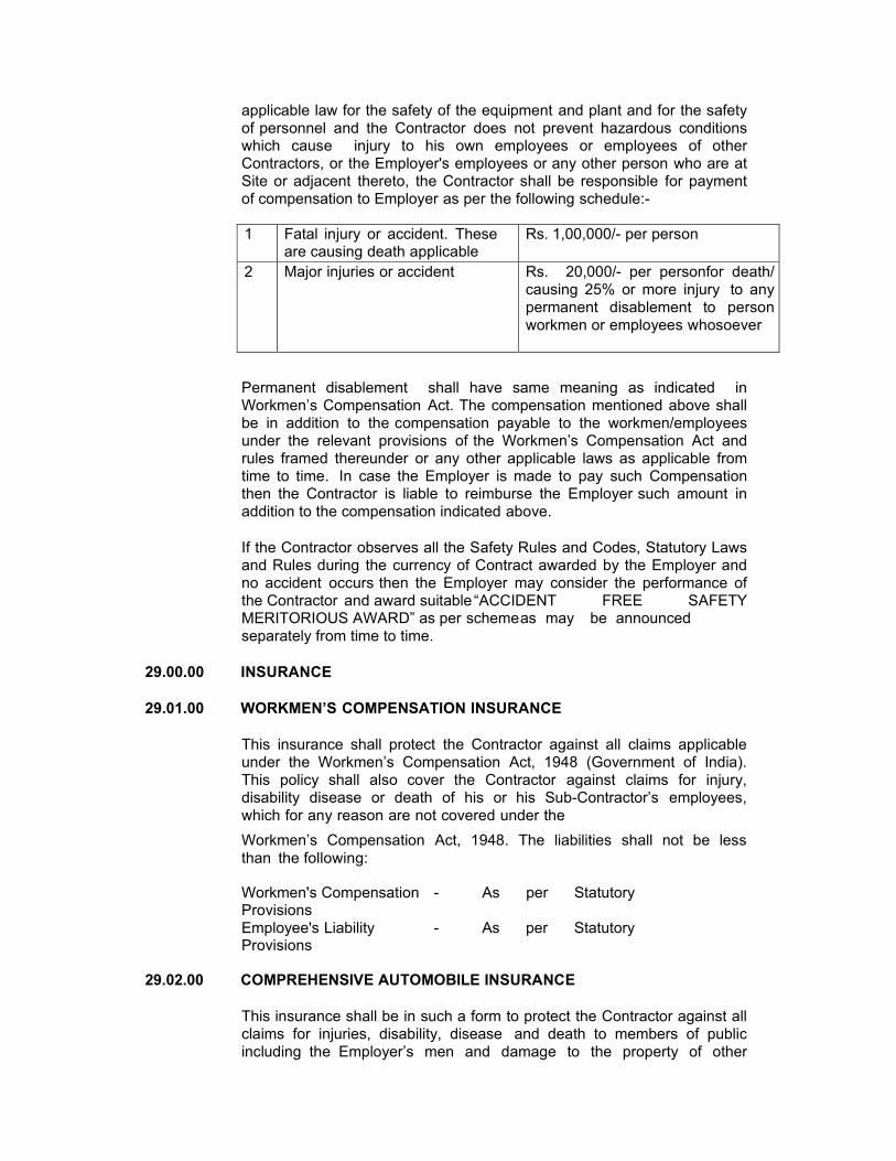
applicable law for the safety of the equipment and plant and for the safety of personnel and the Contractor does not prevent hazardous conditions which cause injury to his own employees or employees of other Contractors, or the Employer's employees or any other person who are at Site or adjacent thereto, the Contractor shall be responsible for payment of compensation to Employer as per the following schedule:-
1 Fatal injury or accident. These
are causing death applicable Rs. 1,00,000/- per person
2 Major injuries or accident Rs. 20,000/- per personfor death/ causing 25% or more injury to any permanent disablement to person workmen or employees whosoever
Permanent disablement shall have same meaning as indicated in Workmen’s Compensation Act. The compensation mentioned above shall be in addition to the compensation payable to the workmen/employees under the relevant provisions of the Workmen’s Compensation Act and rules framed thereunder or any other applicable laws as applicable from time to time. In case the Employer is made to pay such Compensation then the Contractor is liable to reimburse the Employer such amount in addition to the compensation indicated above.
If the Contractor observes all the Safety Rules and Codes, Statutory Laws and Rules during the currency of Contract awarded by the Employer and no accident occurs then the Employer may consider the performance of the Contractor and award suitable “ACCIDENT FREE SAFETY MERITORIOUS AWARD” as per scheme as may be announced separately from time to time.
29.00.00 INSURANCE
29.01.00 WORKMEN’S COMPENSATION INSURANCE
This insurance shall protect the Contractor against all claims applicable under the Workmen’s Compensation Act, 1948 (Government of India). This policy shall also cover the Contractor against claims for injury, disability disease or death of his or his Sub-Contractor’s employees, which for any reason are not covered under the Workmen’s Compensation Act, 1948. The liabilities shall not be less than the following:
Workmen's Compensation - As per Statutory Provisions Employee's Liability - As per Statutory Provisions
29.02.00 COMPREHENSIVE AUTOMOBILE INSURANCE
This insurance shall be in such a form to protect the Contractor against all claims for injuries, disability, disease and death to members of public including the Employer’s men and damage to the property of other
arising from the use of motor vehicles during on or off the Site operations, irrespective of the Ownership of such vehicles. The liability covered shall be as herein indicated:
Fatal Injury : Rs.100,000 each person
: Rs.200,000 each occurrence Property Damage : Rs.100,000 each occurrence
29.03.00 COMPREHENSIVE GENERAL LIABILITY INSURANCE
The insurance shall protect the Contractor against all claims arising from injuries, disabilities, disease or death of members of public or damage to property of others, due to any act or omission on the part of the Contractor, his agents, his employees, his representatives and Sub-Contractors or from riots, strikes and civil commotion.
The hazards to be covered will pertain to all the Works and areas where the Contractor, his Sub-Contractors, his agents and his employees have to perform work pursuant to the Contract.
The above are only illustrative list of insurance covers normally required and it will be the responsibility of the Contractor to maintain all necessary insurance coverage to the extent both in time and amount to take care of all his liabilities either direct or indirect, in pursuance of the Contract.
Part-B LIST OF EXHIBITS
1.0 Site layout of the Solar PV Plant site
2.0 Boundary details of land in possession with NTPC
3.0 Topographical Survey of the Solar Plant site.
4.0 Extracts of Geotechnical studies of the proposed site.
5.0 Single line diagram of 220 kV Switchyard of NTPC Unchahar.
6.0 Protection Single Line diagram of proposed bay at
NTPC Unchahar.
7.0 Indicative SLD of the 10 MWp SPV Plant
8.0 Indicative Array layout for the 10 MW SPV Plant
9.0 List of Mandatory Spares
10.0 Site Photos
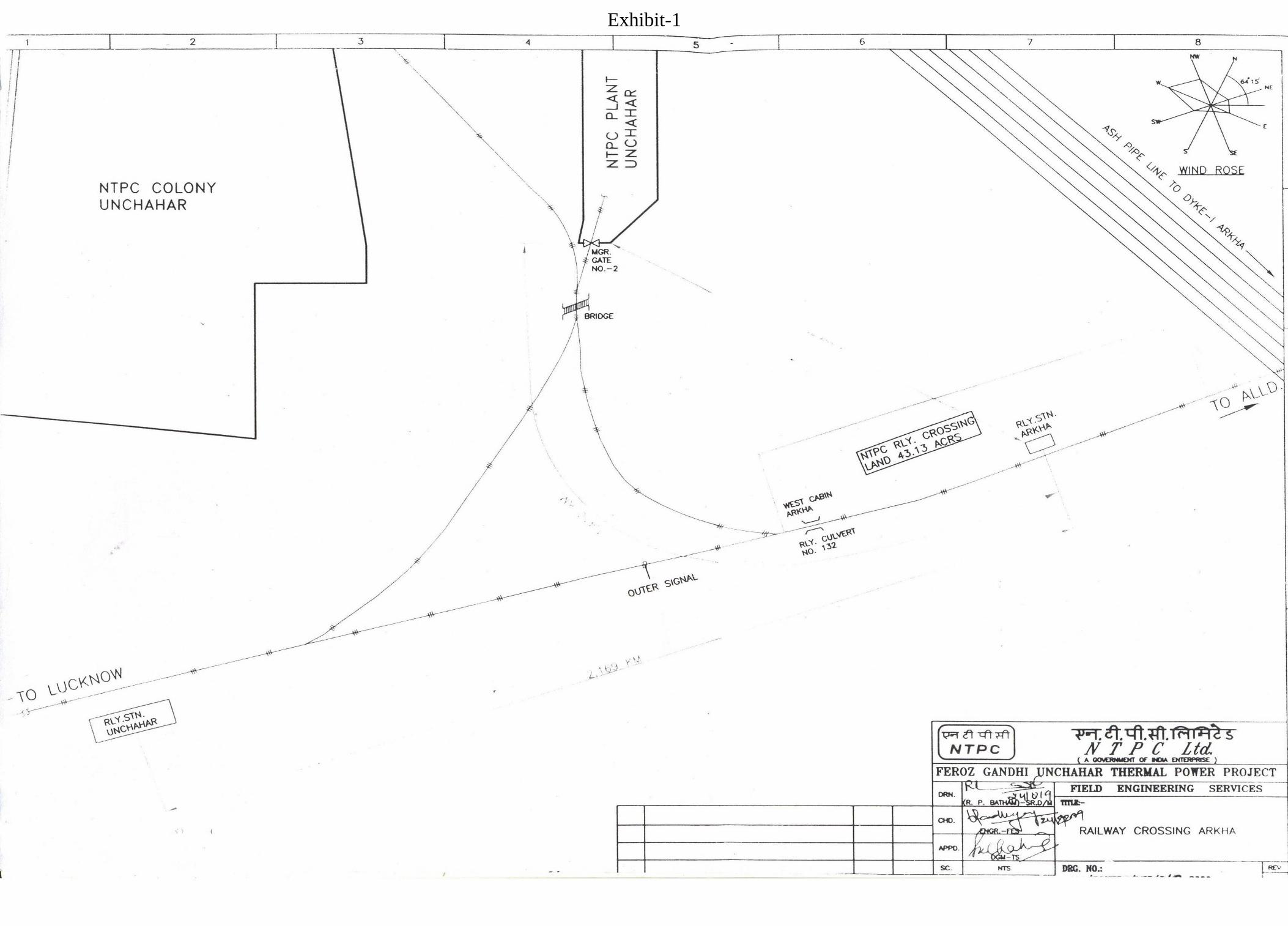
Exhibit-1
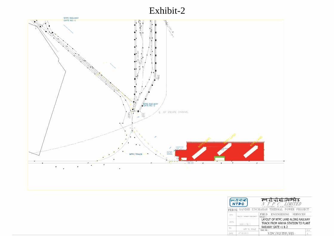
Exhibit-2 NTPC RAILWAY GATE NO.-1
GATE NO.-2
OUTER
UNIDENTYFIED
LAND MANGO
TREES
RAILWAY
CABIN (w)
22.5M
ARKHA STATION
BLDG.
SIGNAL NTPC
TRACK
0.0M
RAILWAY
CULVERT
NO. 132
NTPC RAILWAY
10
.5M
9M
10
.75
M
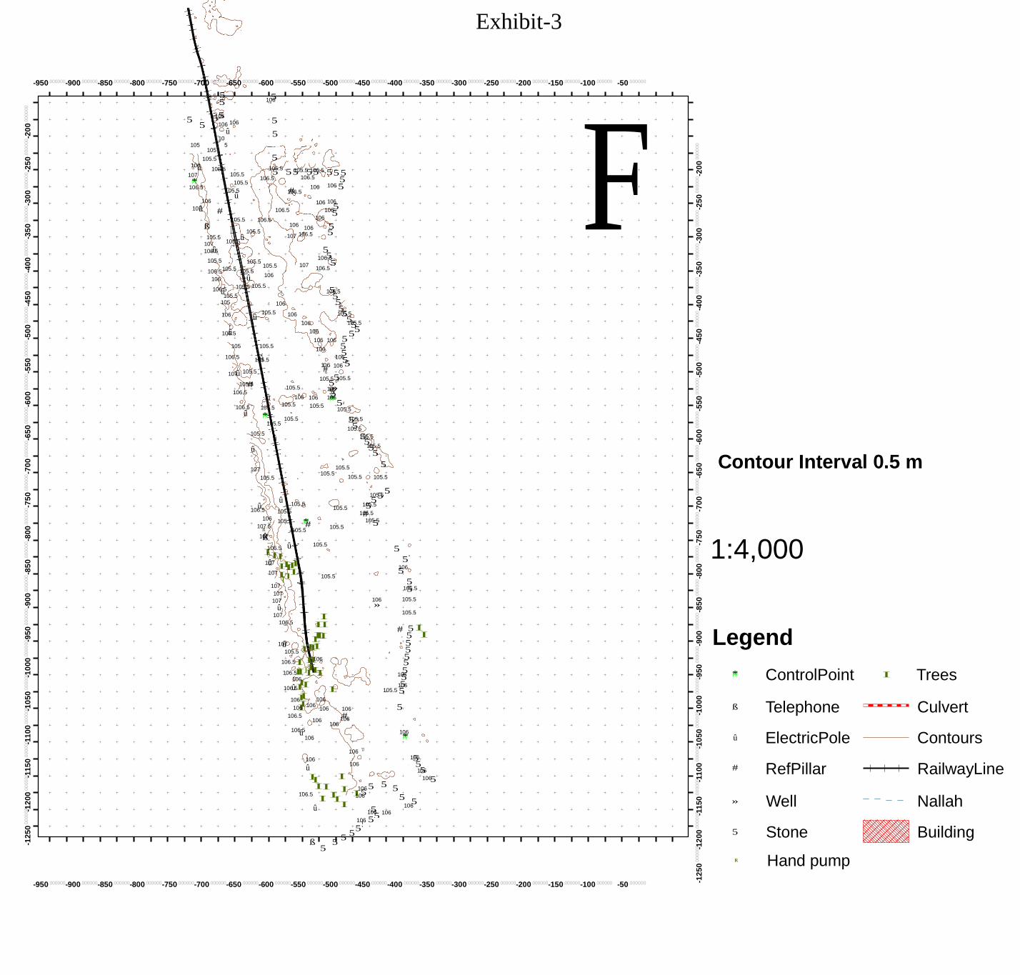
û
5
I1
II
I
I
II I
II
I106
5 5
-12
50
.00
00
0 -0 12
00
.00
00
0 -0 11
50
.00
00
0 -0 11
00
.00
00
0 -0 10
50
.00
00
0 -0 10
00
.00
00
00 -9
50
.00
00
00-9
00
.00
00
00-8
50
.00
00
00-8
00
.00
00
00-7
50
.00
00
00-7
00
.00
00
00-6
50
.00
00
00-6
00
.00
00
00-5
50
.00
00
00-5
00
.00
00
00-4
50
.00
00
00-4
00
.00
00
00-3
50
.00
00
00-3
00
.00
00
00-2
50
.00
00
00-2
00
.00
00
00
Exhibit-3
-950.000000-900.000000-850.000000-800.000000-750.000000-700.000000-650.000000-600.000000-550.000000-500.000000-450.000000-400.000000-350.000000-300.000000-250.000000-200.000000-150.000000-100.000000 -50.000000
F
5 5
5 51055
5 106 106
û 10
5 106
5
5
105 5 105
105.5 5 106û
107
105.5 105.5
1055.5
5 5105.551506.5 5 5 5
#* 106.5
105.5
105.5
106.5 106.5
# 106
5 106 5
106
10û7 #
ß
û
105.5
106.5
106.5
106.5
106
106
106 10
56
1065
106
5
105.5 107
106.5
105.5
105.5
105.5
û 105.5
105.5
5.5
105.5
107 106.5
107
5
5 5
106.55
106.5 106.5
106
10
û 106
106û.5 105.5 105.5
1506.5
105.5 105
106
106û.5
û 105.5
106
106
106
106
5 5 5 1055
5.5
1055.5
55
105
105.5
106 106 5 5
106.5
10û5.5
106 5
1065
107û 105.5
1#06 106 5
5105.5
105#.5
106.5 û
105.5
106 106
1055.5
1505»6
1#*065
106.5
û 105.5
#* 105.5
105.5
105.5
105.5 105.5
5105.5
5 105.5
105.5 û
û
105.5
15055.5
1505.5
5
5
Contour Interval 0.5 m
107
105.5
û
105.5 105.5 105.5
5 15055.5
û 106.5
105.5
105.5
105.5 1055.5
10#5.5 106 105.5 #*#
1055.5 10
R!7.5
1ß0û7
06.5 R!
105.5
û
105.5
105.5
5
5
1:4,000
1û07 IIIII
107I I I
107
107
107
û 107
106.5
105.5
I II
106 »
5106
5 1055.5
105.5
105.5
# 5 I
I 10û7
IIII 5 I 5
Legend 105.5 III
106.5I II106
106.5I III 10I6
106û.5 I I
5 5 5 5
1056
1506
105.5 5
#* ControlPoint
I Trees
106I 10I6
106.5
106
106 106 5 #
ß Telephone Culvert 106
106û.5 106
106 106
1#*06
û ElectricPole
Contours
106
û
II
106
106
I 5
1506
5 1506
1065
# RefPillar
RailwayLine II I
I1506 5 5
106.5
I II
106 5 5
û
ß 5
5
I
106
55
5
5
106 106
5
106
» Well
5 Stone
Nallah
Building
R! Hand pump
-950.000000-900.000000-850.000000-800.000000-750.000000-700.000000-650.000000-600.000000-550.000000-500.000000-450.000000-400.000000-350.000000-300.000000-250.000000-200.000000-150.000000-100.000000 -50.000000
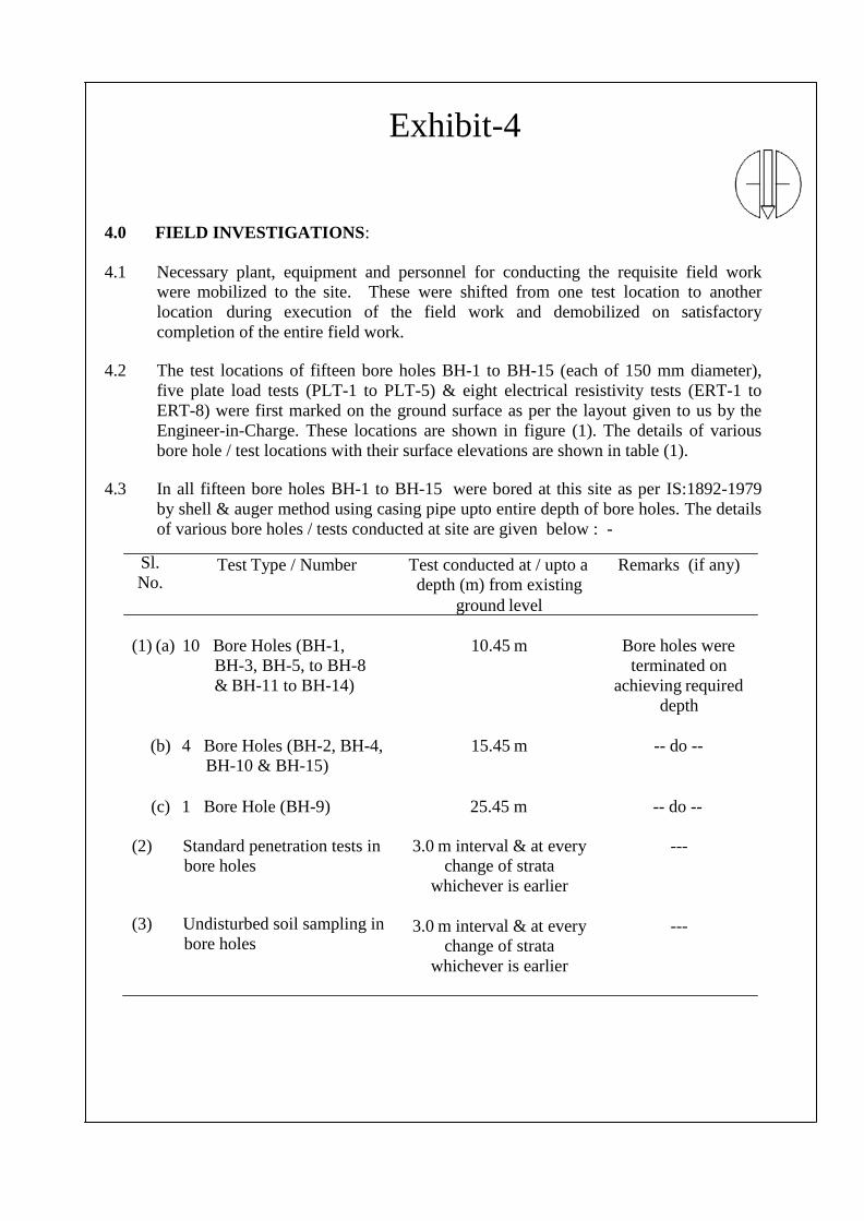
Exhibit-4
4.0 FIELD INVESTIGATIONS:
4.1 Necessary plant, equipment and personnel for conducting the requisite field work
were mobilized to the site. These were shifted from one test location to another
location during execution of the field work and demobilized on satisfactory
completion of the entire field work. 4.2 The test locations of fifteen bore holes BH-1 to BH-15 (each of 150 mm diameter),
five plate load tests (PLT-1 to PLT-5) & eight electrical resistivity tests (ERT-1 to
ERT-8) were first marked on the ground surface as per the layout given to us by the
Engineer-in-Charge. These locations are shown in figure (1). The details of various
bore hole / test locations with their surface elevations are shown in table (1). 4.3 In all fifteen bore holes BH-1 to BH-15 were bored at this site as per IS:1892-1979
by shell & auger method using casing pipe upto entire depth of bore holes. The details
of various bore holes / tests conducted at site are given below : -
Sl.
No. Test Type / Number Test conducted at / upto a
depth (m) from existing
ground level
Remarks (if any)
(1) (a) 10 Bore Holes (BH-1,
BH-3, BH-5, to BH-8
& BH-11 to BH-14)
10.45 m Bore holes were
terminated on
achieving required
depth
(b) 4 Bore Holes (BH-2, BH-4,
BH-10 & BH-15)
15.45 m -- do --
(c) 1 Bore Hole (BH-9) 25.45 m -- do --
(2) Standard penetration tests in
bore holes
3.0 m interval & at every
change of strata
whichever is earlier
---
(3) Undisturbed soil sampling in
bore holes 3.0 m interval & at every
change of strata
whichever is earlier
---
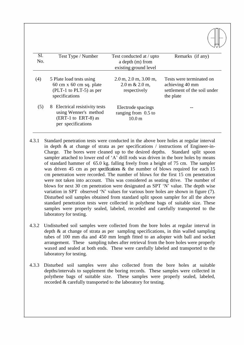
Sl.
No. Test Type / Number Test conducted at / upto
a depth (m) from
existing ground level
Remarks (if any)
(4) 5 Plate load tests using
60 cm x 60 cm sq. plate
(PLT-1 to PLT-5) as per
specifications
2.0 m, 2.0 m, 3.00 m,
2.0 m & 2.0 m,
respectively
Tests were terminated on
achieving 40 mm
settlement of the soil under
the plate
(5) 8 Electrical resistivity tests
using Wenner's method
(ERT-1 to ERT-8) as
per specifications
Electrode spacings --
ranging from 0.5 to
10.0 m
4.3.1 Standard penetration tests were conducted in the above bore holes at regular interval
in depth & at change of strata as per specifications / instructions of Engineer-in-
Charge. The bores were cleaned up to the desired depths. Standard split spoon
sampler attached to lower end of ‘A’ drill rods was driven in the bore holes by means
of standard hammer of 65.0 kg. falling freely from a height of 75 cm. The sampler
was driven 45 cm as per specifications & the number of blows required for each 15
cm penetration were recorded. The number of blows for the first 15 cm penetration
were not taken into account. This was considered as seating drive. The number of
blows for next 30 cm penetration were designated as SPT ‘N’ value. The depth wise
variation in SPT observed ‘N’ values for various bore holes are shown in figure (7).
Disturbed soil samples obtained from standard split spoon sampler for all the above
standard penetration tests were collected in polythene bags of suitable size. These
samples were properly sealed, labeled, recorded and carefully transported to the
laboratory for testing.
4.3.2 Undisturbed soil samples were collected from the bore holes at regular interval in
depth & at change of strata as per sampling specifications, in thin walled sampling
tubes of 100 mm dia and 450 mm length fitted to an adopter with ball and socket
arrangement. These sampling tubes after retrieval from the bore holes were properly
waxed and sealed at both ends. These were carefully labeled and transported to the
laboratory for testing.
4.3.3 Disturbed soil samples were also collected from the bore holes at suitable
depths/intervals to supplement the boring records. These samples were collected in
polythene bags of suitable size. These samples were properly sealed, labeled,
recorded & carefully transported to the laboratory for testing.
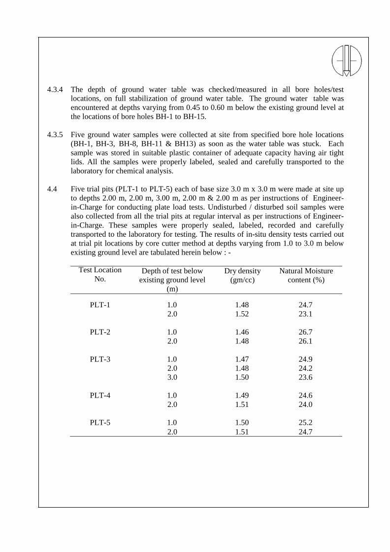
4.3.4 The depth of ground water table was checked/measured in all bore holes/test
locations, on full stabilization of ground water table. The ground water table was
encountered at depths varying from 0.45 to 0.60 m below the existing ground level at
the locations of bore holes BH-1 to BH-15.
4.3.5 Five ground water samples were collected at site from specified bore hole locations
(BH-1, BH-3, BH-8, BH-11 & BH13) as soon as the water table was stuck. Each
sample was stored in suitable plastic container of adequate capacity having air tight
lids. All the samples were properly labeled, sealed and carefully transported to the
laboratory for chemical analysis.
4.4 Five trial pits (PLT-1 to PLT-5) each of base size 3.0 m x 3.0 m were made at site up
to depths 2.00 m, 2.00 m, 3.00 m, 2.00 m & 2.00 m as per instructions of Engineer-
in-Charge for conducting plate load tests. Undisturbed / disturbed soil samples were
also collected from all the trial pits at regular interval as per instructions of Engineer-
in-Charge. These samples were properly sealed, labeled, recorded and carefully
transported to the laboratory for testing. The results of in-situ density tests carried out
at trial pit locations by core cutter method at depths varying from 1.0 to 3.0 m below
existing ground level are tabulated herein below : -
Test Location
No. Depth of test below
existing ground level
(m)
Dry density
(gm/cc)
Natural Moisture
content (%)
PLT-1 1.0 1.48 24.7
2.0 1.52 23.1
PLT-2 1.0 1.46 26.7
2.0 1.48 26.1
PLT-3 1.0 1.47 24.9
2.0 1.48 24.2
3.0 1.50 23.6
PLT-4 1.0 1.49 24.6
2.0 1.51 24.0
PLT-5 1.0 1.50 25.2
2.0 1.51 24.7
4.5 Five plate load tests (PLT-1 to PLT-5) were conducted at specified locations at depths
2.00 m, 2.00 m, 3.00 m 2.00 m & 2.00 m respectively below the existing ground level
as per specifications & instructions of Engineer-in-Charge. The load was applied in
small increments by means of hydraulic jack by taking reaction from a loaded
platform. The settlements of the plate corresponding to each of these load increments
were measured through dial gauges for various time intervals. The next increment
was applied only when the settlement became constant or when the rate of settlement
considered appreciably reduced. All the tests were terminated on achieving 40 mm
settlement of the soil under the plate as per specifications. The load settlement curves
on natural scale & log-log scale are presented in figures (8) to (17).
4.6 Eight electrical resistivity tests (ERT-1 to ERT-8) were conducted at the specified
locations by Wenner's method (four electrodes method) as per specifications. The test
locations as provided to us at site are shown in figure (1). The electrodes and porous
pots were suitably located and after initial setting of the resistivity meter, resistance
readings were noted in direct and reverse positions. There after the electrode spacing
was changed and the procedure was repeated adopting electrode spacings ranging
from 0.50 to 10.00 m as per the instructions of Engineer-in-Charge. The tests results
are shown in tables (23) to (30) & figures (18) to (19).
5.0 LABORATORY INVESTIGATIONS:
5.1 The following laboratory tests were conducted on selected soil samples recovered
from various bore hole / test locations : -
(a) Bulk density and Moisture content
(b) Sieve analysis
(c) Hydrometer analysis
(d) Liquid limit & Plastic limits
(e) Shrinkage limit
(f) Specific gravity
(g) Swell pressure
(h) Free Swell Index
(i) Unconfined compressive strength
(j) Direct shear test
(k) Triaxial Shear test
(l) One Dimensional consolidation test
(m) Chemical analysis on five soil & five water samples
All the above laboratory tests were carried out as per relevant Indian Standards. The results of laboratory tests are shown in tables (2) to (22), (31) to (34) & figures (20)
to (105). The grain size analysis curves are presented in figures (24) to (41). The stress strain curves & failure envelopes for triaxial / Direct shear tests are shown in
(42) to (69). Shear strength tests were conducted on saturated soil samples at suitable pressure ranges so as to obtain the in-situ strata conditions. The values of modulus of
Elasticity (E) (taken as the tangent modulus at the stress level equal to one-half the maximum deviator stress applied during the tests) obtained from triaxial shear tests
are shown in table (31). The results of one dimensional consolidation tests are shown
in figures (70) to (105). Sample calculations for computation of compression Index (Cc) & Coefficient of volume compressibility (mv) are shown in table (32). The depth
wise variation in soil strength parameters are shown vide figures (20) to (23). The results of chemical analysis on soil samples are shown in table (33) & of ground
water samples in table (34). All the above tests were carried out as per laboratory
schedule approved by the client. All the soil samples were identified and classified as per IS:1498-1970.
6.0 TEST RESULTS & INTERPRETATIONS:
6.1 The bore logs of all bore holes & trial pits are given in tables (2) to (22). The cross-
sections along various bore holes are shown in figures (2) to (6). The study of bore
logs/results of laboratory and other field tests as above from ground level reveal
that: -
(a) From existing ground surface to 4.00 m depth consists predominantly of fine gained
soils i.e. clayey silt of low to medium plasticity (CI/CL) & sandy silt of low plasticity
(CL) having SPT field ‘N’ values mostly ranging from 4 to 12 showing medium to
stiff consistency of the strata. However, at the location of bore hole BH-7 the sub-soil
strata from existing ground surface 1.00 m depth consists of filled-up soil.
(b) From depth 4.00 m to 10.00 m depth consists predominantly of fine grained soils i.e.
clayey silt of low to medium plasticity (CI/CL) & sandy silt of low plasticity (CL)
having SPT field ‘N’ values mostly ranging from 8 to 22 showing medium
consistency of the strata to very stiff consistency of the strata.
(c) From depth 1.00 m to 15.45 – 25.45 m depths consists predominantly of fine gained
soils i.e. clayey silt of low to high plasticity (CH/CI/CL) having SPT field ‘N’ values
mostly ranging from 12 to 32 showing stiff consistency of the strata to hard
consistency of the strata.
6.2 The load Vs settlement curves of five plate load tests (PLT-1 to PLT-5) conducted at
specified locations at depths 2.00 m, 2.00 m, 3.00 m, 2.00 m & 2.00 m respectively below the existing ground level are shown in figures (8) to (17). From the study of the
load Vs settlement curves it is revealed that :-
PLT-1
(a) Net ultimate bearing capacity of 2.30 kg/cm
2 is obtained. On applying a factor of
safety of 2.5, net safe bearing capacity of 9.2 t/m2
is arrived at 2.00 m depth below
the existing ground level.
(b) The modulus of sub-grade reaction (K-value) worked out to be 2.77 Kg/cm3
for plate
size of 60.0 cm x 60.0 cm. after applying correction for bending and saturation.
(c) The modulus of elasticity worked out to be 4.17 kg/cm2.
PLT-2
(a) Net ultimate bearing capacity of 2.10 kg/cm
2 is obtained. On applying a factor of
safety of 2.5, net safe bearing capacity of 8.4 t/m2
is arrived at 2.00 m depth below
the existing ground level.
(b) The modulus of sub-grade reaction (K-value) worked out to be 1.64 Kg/cm3
for plate
size of 60.0 cm x 60.0 cm. after applying correction for bending and saturation.
(c) The modulus of elasticity worked out to be 2.00 kg/cm2.
PLT-3
(a) Net ultimate bearing capacity of 2.70 kg/cm
2 is obtained. On applying a factor of
safety of 2.5, net safe bearing capacity of 10.8 t/m2
is arrived at 3.00 m depth below
the existing ground level.
(b) The modulus of sub-grade reaction (K-value) worked out to be 1.67 Kg/cm3
for plate
size of 60.0 cm x 60.0 cm. after applying correction for bending and saturation.
(c) The modulus of elasticity worked out to be 2.37 kg/cm2.
PLT-4
(a) Net ultimate bearing capacity of 2.90 kg/cm2
is obtained. On applying a factor of
safety of 2.5, net safe bearing capacity of 11.6 t/m2
is arrived at 2.00 m depth below the existing ground level.
(b) The modulus of sub-grade reaction (K-value) worked out to be 1.56 Kg/cm3
for plate
size of 60.0 cm x 60.0 cm. after applying correction for bending and saturation.
(c) The modulus of elasticity worked out to be 2.50 kg/cm2.
PLT-5
(a) Net ultimate bearing capacity of 2.55 kg/cm
2 is obtained. On applying a factor of
safety of 2.5, net safe bearing capacity of 10.2 t/m2
is arrived at 2.00 m depth below
the existing ground level.
(b) The modulus of sub-grade reaction (K-value) worked out to be 2.13 Kg/cm3
for plate
size of 60.0 cm x 60.0 cm. after applying correction for bending and saturation.
(c) The modulus of elasticity worked out to be 2.43 kg/cm2.
6.3 From the results of eight electrical resistivity tests (ERT-1 to ERT-8)
shown in tables (23) to (30) & figures (18) to (19), it is revealed that the
values of average resistivity mostly ranged from 10.28 to 37.50 Ohm-m for
electrode spacings varying from 0.5 to 10.0 m.
6.4 The ground water table though encountered at depths varying from 0.45 to
0.60 m depths below the existing ground level at the locations of various
bore holes, it may rise up during heavy rains/rainy season or go down during
dry season. Therefore, for analysis of various foundations the ground water
table has been considered to rise upto the existing ground level.
6.5 From the results of chemical analysis of five soil samples from selected
depths in bore holes BH-2, BH-5, BH-9, BH-12 & BH-15 as shown in table
(33), it is revealed that pH value ranged from 6.6 to 7.4, Carbonate content
(as CO3) Nil, Sulphate (as SO4) from 0.0136 % to 0.0285 %, Sulphate
content (as SO3) from 0.0113 % to
0.0237 %, Chloride content (as CL) from 0.0195 % to 0.0320 %, Nitrate
Content from 0.0037 % to 0.0074 % & Organic matter from 0.0178 % to
0.0425 %. From the study of above results, it is revealed that the various
contents are within permissible limits as per IS: 456-2000 & no special
precautions are required due to this.
6.6 From the results of chemical analysis of five water samples from bore
holes BH-1, BH-3, BH-8, BH-11 & BH13) as shown in table (34), it is
revealed that pH value ranged from 7.2 to 7.9, Carbonate content (as CO3)
Nil, Sulphate content (as SO4) from 42 ppm to 88 ppm, Sulphate content (as
SO3) from 35 ppm to 73 ppm, Chloride content (as CL) from 62 ppm to 187
ppm, Nitrate content from 0.0025 % to 0.0078 %, Organic matter from
0.0143 % to 0.0238 %, Turbidity from 150 to 537
NTU & specific conductivity from 160 to 560 μ mhos/cm. The various
contents are below the permissible limits as per IS:456-2000 & no special
precautions are required due to this.
Exhibit-5
Exhibit-6
630 KWPV Array
PCU
VCB
630 KW
1600 A ACB
LTPanel
10 MW HT Panel
xxxV/xxxV/33KVONAN 1.26MVA
Transformer
630 KWPV Array
PCU630 KW
1250A
630AVCB
1600 A ACB
LTPanel
VCP
TVMPT
CT
ABT Meter (main)
MAR'13
GOS
CSS CSS
630AVCB
Auxiliary Supply
33KV/415V, ONAN250KVA Transformer
To 220 KVswitchyardof NTPC
This drawing is tentative andpreliminary only
Notes:1. Building Blocks: a) 2X630 KWp PV array b) 2X630 KW PCU (transformer less) c) Each block-1.260 MW d) 8X1.26 MW connected to a bus in HT Panel
to form 10.08 MW2. Metering & protection provided:
a) at CSS levelb) at 10.08MW level
3. ACB can be part of PCU(inverter).4. This scheme depends on type of PCU5. SCADA output from each inverter room will be
taken to SCADA room located in CMCS.6. Protection in CSS:
a) LT switchgear: overcurrent, shortcircuit andearthfaultb) Transformer: Oil Temp., Winding Temp.,and Pressure Relief Devicec) HT switchgear: Overcurrent and Earth fault
Details of Line PT block
core1: Cl-3Pcore2: Cl-0.2s
Line PT
630AVCB 630A
VCB630AVCB
630AVCB
630AVCB
630AVCB
630AVCB 630A
VCB
630AVCB
TVMPT
CT
ABT Meter (check)EXHIBIT - 7
42240 nos
PV ARRAY CAPACITY
PV Modules in series string
Total No. of strings
Total no.of PV Modules (240Wp)
String Monitoring Units (SMU)
10.137 MWp
24 nos
1760 nos
64 Nos (16 i/p-1 o/p)
ARRAY DETAILS
No. of Inverters (630kW)
16 nos
Series strings/630kW 110 nos
At Latitude deg +15 deg
Distance between rows:
So, the distance between row is = 3.6 mtrs
(2xheight of the PV modules mounted on structure)
1.8
3.62.5
1.25
1.25
1x12-240W STRUCTURE
2.5
LEGEND
Centralised Main Control System
CMCS
250 sq.mtrs (RCC Type)
Compact Sub Station, 8 nos.
3.83x 2.33 x2.41(h) mtrs
Prefab Inverter Rooms, 8 nos
7x4
CSS
CS1-CS8
IR1-IR8
1
IR1
CS1
110-3
110-4
110-6
IR3
CS3
IR5CS5
IR6
CS6
IR7
CS7
PV ARRAY LAYOUT
FOR NTPC UNCHAHAR
7.5 mtr gap
from Rly line side
CMCS
4.5 mtr gap from Boundary line
Tentative location
2x12-240W STRUCTURE
13.6
X
6.8
2.5 Y
BURIEL GROUND
110-1
110-14
110-2
IR2
CS2
110-5
IR3
CS3
110-7
110-8
110-9
110-10
110-11
110-12
110-13
110-15
IR8
CS8
THIS DRAWING IS TENTATIVE AND PRELIMINARY
EXHIBIT - 8
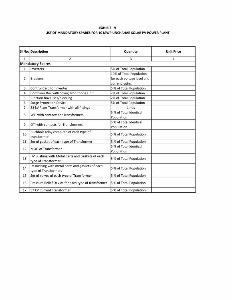
Sl No: Description Quantity Unit Price
1 2 3 4
1 Inverters 5% of Total Population
2 Breakers
10% of Total Population
for each voltage level and
current rating
3 Control Card for Inverter 5 % of Total Population
4 Combiner Box with String Monitoring Unit 2% of Total Population
5 Junction box fuses/blocking 2% of Total Population
6 Surge Protection Device 5% of Total Population
7 33 kV Plant Transformer with all fittings 1 nos
8 WTI with contacts for Transformers5 % of Total Identical
Population
9 OTI with contacts for Transformers5 % of Total Identical
Population
10Buchholz relay complete of each type of
transformer5 % of Total Population
11 Set of gasket of each type of Transformer 5 % of Total Population
12 MOG of Transformer5 % of Total Identical
Population
13HV Bushing with Metal parts and Gaskets of each
type of Transformer5 % of Total Population
14LV Bushing with metal parts and gaskets of each
type of Transformers5 % of Total Population
15 Set of valves of each type of Transformer 5 % of Total Population
16 Pressure Relief Device for each type of transformer 5 % of Total Population
17 33 kV Current Transformer 5 % of Total Population
Mandatory Spares
EXHIBIT - 9
LIST OF MANDATORY SPARES FOR 10 MWP UNCHAHAR SOLAR PV POWER PLANT
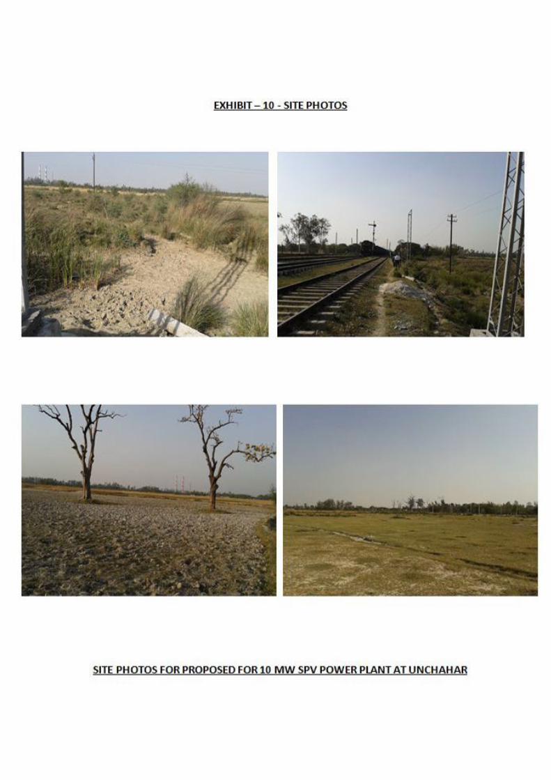
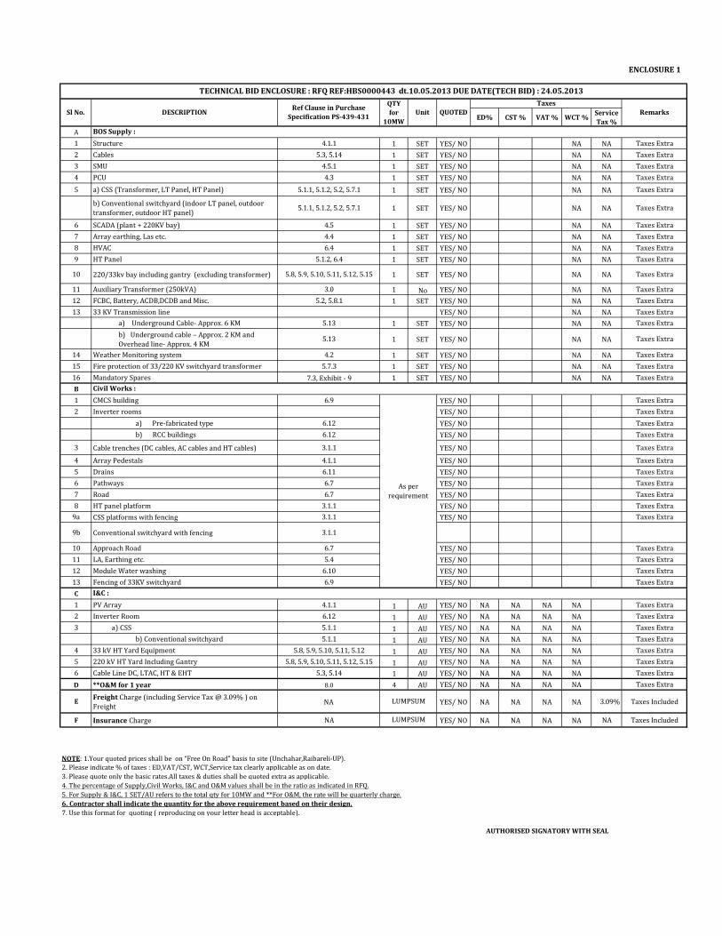
ENCLOSURE 1
ED% CST % VAT % WCT %Service
Tax %
A
1 Structure 4.1.1 1 SET YES/ NO NA NA Taxes Extra
2 Cables 5.3, 5.14 1 SET YES/ NO NA NA Taxes Extra
3 SMU 4.5.1 1 SET YES/ NO NA NA Taxes Extra
4 PCU 4.3 1 SET YES/ NO NA NA Taxes Extra
5 a) CSS (Transformer, LT Panel, HT Panel) 5.1.1, 5.1.2, 5.2, 5.7.1 1 SET YES/ NO NA NA Taxes Extra
b) Conventional switchyard (indoor LT panel, outdoor
transformer, outdoor HT panel)5.1.1, 5.1.2, 5.2, 5.7.1 1 SET YES/ NO NA NA Taxes Extra
6 SCADA (plant + 220KV bay) 4.5 1 SET YES/ NO NA NA Taxes Extra
7 Array earthing, Las etc. 4.4 1 SET YES/ NO NA NA Taxes Extra
8 HVAC 6.4 1 SET YES/ NO NA NA Taxes Extra
9 HT Panel 5.1.2, 6.4 1 SET YES/ NO NA NA Taxes Extra
10 220/33kv bay including gantry (excluding transformer) 5.8, 5.9, 5.10, 5.11, 5.12, 5.15 1 SET YES/ NO NA NA Taxes Extra
11 Auxiliary Transformer (250kVA) 3.0 1 No YES/ NO NA NA Taxes Extra
12 FCBC, Battery, ACDB,DCDB and Misc. 5.2, 5.8.1 1 SET YES/ NO NA NA Taxes Extra
13 33 KV Transmission line YES/ NO NA NA Taxes Extra
a) Underground Cable- Approx. 6 KM 5.13 1 SET YES/ NO NA NA Taxes Extra
b) Underground cable – Approx. 2 KM and
Overhead line- Approx. 4 KM5.13 1 SET YES/ NO NA NA Taxes Extra
14 Weather Monitoring system 4.2 1 SET YES/ NO NA NA Taxes Extra
15 Fire protection of 33/220 KV switchyard transformer 5.7.3 1 SET YES/ NO NA NA Taxes Extra
16 Mandatory Spares 7.3, Exhibit - 9 1 SET YES/ NO NA NA Taxes Extra
B
1 CMCS building 6.9 YES/ NO Taxes Extra
2 Inverter rooms YES/ NO Taxes Extra
a) Pre-fabricated type 6.12 YES/ NO Taxes Extra
b) RCC buildings 6.12 YES/ NO Taxes Extra
3 Cable trenches (DC cables, AC cables and HT cables) 3.1.1 YES/ NO Taxes Extra
4 Array Pedestals 4.1.1 YES/ NO Taxes Extra
5 Drains 6.11 YES/ NO Taxes Extra
6 Pathways 6.7 YES/ NO Taxes Extra
7 Road 6.7 YES/ NO Taxes Extra
8 HT panel platform 3.1.1 YES/ NO Taxes Extra
9a CSS platforms with fencing 3.1.1 YES/ NO Taxes Extra
9b Conventional switchyard with fencing 3.1.1
10 Approach Road 6.7 YES/ NO Taxes Extra
11 LA, Earthing etc. 5.4 YES/ NO Taxes Extra
12 Module Water washing 6.10 YES/ NO Taxes Extra
13 Fencing of 33KV switchyard 6.9 YES/ NO Taxes Extra
C
1 PV Array 4.1.1 1 AU YES/ NO NA NA NA NA Taxes Extra
2 Inverter Room 6.12 1 AU YES/ NO NA NA NA NA Taxes Extra
3 a) CSS 5.1.1 1 AU YES/ NO NA NA NA NA Taxes Extra
b) Conventional switchyard 5.1.1 1 AU YES/ NO NA NA NA NA Taxes Extra
4 33 kV HT Yard Equipment 5.8, 5.9, 5.10, 5.11, 5.12 1 AU YES/ NO NA NA NA NA Taxes Extra
5 220 kV HT Yard Including Gantry 5.8, 5.9, 5.10, 5.11, 5.12, 5.15 1 AU YES/ NO NA NA NA NA Taxes Extra
6 Cable Line DC, LTAC, HT & EHT 5.3, 5.14 1 AU YES/ NO NA NA NA NA Taxes Extra
D **O&M for 1 year 8.0 4 AU YES/ NO NA NA NA NA Taxes Extra
EFreight Charge (including Service Tax @ 3.09% ) on
FreightNA YES/ NO NA NA NA NA 3.09% Taxes Included
F Insurance Charge NA YES/ NO NA NA NA NA NA Taxes Included
2. Please indicate % of taxes : ED,VAT/CST, WCT,Service tax clearly applicable as on date.
3. Please quote only the basic rates.All taxes & duties shall be quoted extra as applicable.
4. The percentage of Supply,Civil Works, I&C and O&M values shall be in the ratio as indicated in RFQ.
5. For Supply & I&C, 1 SET/AU refers to the total qty for 10MW and **For O&M, the rate will be quarterly charge.
6. Contractor shall indicate the quantity for the above requirement based on their design.
7. Use this format for quoting ( reproducing on your letter head is acceptable).
AUTHORISED SIGNATORY WITH SEAL
NOTE: 1.Your quoted prices shall be on “Free On Road” basis to site (Unchahar,Raibareli-UP).
As per
requirement
TECHNICAL BID ENCLOSURE : RFQ REF:HBS0000443 dt.10.05.2013 DUE DATE(TECH BID) : 24.05.2013
Sl No. DESCRIPTIONQTY
for
10MW
Unit
Taxes
RemarksQUOTEDRef Clause in Purchase
Specification PS-439-431
LUMPSUM
LUMPSUM
BOS Supply :
Civil Works :
I&C :
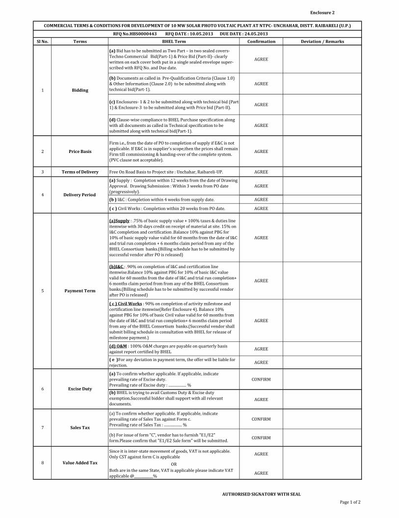
Enclosure 2
Sl No. Terms BHEL Term Confirmation Deviation / Remarks
(a) Bid has to be submitted as Two Part – in two sealed covers-Techno Commercial Bid(Part-1) & Price Bid (Part-II)- clearly written on each cover both put in a single sealed envelope super-scribed with RFQ No. and Due date.
AGREE
(b) Documents as called in Pre-Qualification Criteria (Clause 1.0) & Other Information (Clause 2.0) to be submitted along with technical bid(Part-1).
AGREE
(c) Enclosures- 1 & 2 to be submitted along with technical bid (Part-1) & Enclosure-3 to be submitted along with Price bid (Part-II).
AGREE
(d) Clause-wise compliance to BHEL Purchase specification along with all documents as called in Technical specification to be submitted along with technical bid(Part-1).
AGREE
2 Price Basis
Firm i.e., from the date of PO to completion of supply if E&C is not applicable. If E&C is in supplier's scope,then the prices shall remain Firm till commissioning & handing-over of the complete system.(PVC clause not acceptable).
AGREE
3 Terms of Delivery Free On Road Basis to Project site : Unchahar, Raibareli-UP. AGREE
(a) Supply : Completion within 12 weeks from the date of Drawing Approval. Drawing Submission : Within 3 weeks from PO date (progressively).
AGREE
(b ) I&C : Completion within 4 weeks from supply date. AGREE
( c ) Civil Works : Completion within 20 weeks from PO date. AGREE
(a)Supply : .75% of basic supply value + 100% taxes & duties line itemwise with 30 days credit on receipt of material at site. 15% on I&C completion and certification .Balance 10% against PBG for 10% of basic supply value valid for 60 months from the date of I&C and trial run completion + 6 months claim period from any of the BHEL Consortium banks.(Billing schedule has to be submitted by successful vendor after PO is released)
AGREE
(b)I&C : .90% on completion of I&C and certification line itemwise.Balance 10% against PBG for 10% of basic I&C value valid for 60 months from the date of I&C and trial run completion+ 6 months claim period from from any of the BHEL Consortium banks.(Billing schedule has to be submitted by successful vendor after PO is released)
AGREE
( c ) Civil Works : 90% on completion of activity milestone and certification line itemwise(Refer Enclosure 4). Balance 10% against PBG for 10% of basic Civil value valid for 60 months from the date of I&C and trial run completion+ 6 months claim period from any of the BHEL Consortium banks.(Successful vendor shall submit billing schedule in consultation with BHEL for release of milestone payment.)
AGREE
(d) O&M : 100% O&M charges are payable on quarterly basis against report certified by BHEL
AGREE
( e )For any deviation in payment term, the offer will be liable for rejection.
AGREE
(a) To confirm whether applicable. If applicable, indicate prevailing rate of Excise duty. Prevailing rate of Excise duty : ................... %
CONFIRM
(b) BHEL is trying to avail Customs Duty & Excise duty exemption.Successful bidder shall support with all relevant documents.
AGREE
(a) To confirm whether applicable. If applicable, indicate prevailing rate of Sales Tax against Form c. Prevailing rate of Sales Tax : ................... %
CONFIRM
(b) For issue of form "C", vendor has to furnish "E1/E2" form.Please confirm that "E1/E2 Sale form" will be submitted.
CONFIRM
Since it is inter-state movement of goods, VAT is not applicable. Only CST against form C is applicable
AGREE
OR
Both are in the same State, VAT is applicable please indicate VAT applicable @___________%
AGREE
AUTHORISED SIGNATORY WITH SEAL
Page 1 of 2
Value Added Tax8
COMMERCIAL TERMS & CONDITIONS FOR DEVELOPMENT OF 10 MW SOLAR PHOTO VOLTAIC PLANT AT NTPC- UNCHAHAR, DISTT. RAIBARELI (U.P.)
Excise Duty6
Sales Tax7
Bidding1
Delivery Period 4
Payment Term5
RFQ No.HBS0000443 RFQ DATE : 10.05.2013 DUE DATE : 24.05.2013
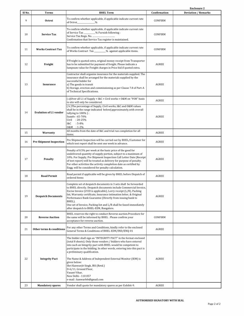
Enclosure 2
Sl No. Terms BHEL Term Confirmation Deviation / Remarks
9 OctroiTo confirm whether applicable, if applicable indicate current rate of Octroi_________________%
CONFIRM
10 Service Tax
To confirm whether applicable, if applicable indicate current rate of Service Tax ___________% Furnish following :Service Tax Regn. No. …………………………..Confirmation that Service Tax register is maintained.
CONFIRM
11 Works Contract TaxTo confirm whether applicable, if applicable indicate current rate of Works Contract Tax ___________% against applicable items.
CONFIRM
12 Freight If Freight is quoted extra, original money receipt from Transporter has to be submitted for payment of freight. Please indicate a lumpsum value for Freight charges in Price bid if quoted extra.
AGREE
13 Insurance
Contractor shall organize insurance for the materials supplied. The insurance shall be arranged for the materials supplied by the successful bidder for a) The goods in transitb) Storage, erection and commissioning as per Clause 7.8 of Part-A of Technical Specifications.
AGREE
( a)Over all L1 of Supply + I&C + Civil works + O&M on “FOR” basis to site will only be considered.
AGREE
( b )The percentage of Supply, Civil works, I&C and O&M values shall be in the range indicated below(approximately,with overall tallying to 100% ) : Supply : 65-70% Civil : 20-25%
I&C : 5-8%
O&M : 1-2%
15 Warranty 60 months from the date of I&C and trial run completion for all items.
AGREE
16 Pre Shipment Inspection Pre Shipment Inspection will be carried out by BHEL/Customer for which test report shall be sent one week in advance.
AGREE
17 Penalty
Penalty of 0.5% per week at the basic price of the good for undelivered quantity of supply portion, subject to a maximum of 10%. For Supply, Pre Shipment Inspection Call Letter Date (Receipt of test report) will be treated as delivery for purpose of penalty. For other activities the activity completion date as certified by Engg. will be considered for penalty calculation.
AGREE
18 Road PermitRoad permit if applicable will be given by BHEL before Dispatch of ordered Items
AGREE
19 Despatch Documents
Complete set of despatch documents in 3 sets shall be forwarded to BHEL directly. Despatch documents include Commercial Invoice, Excise Invoice (if ED is applicable), Lorry receipt (L/R), Packing list, Warranty certificate, Insurance intimation letter, & Original Performance Bank Guarantee (Directly from issuing bank to BHEL).One set of Invoice, Packing list and L/R shall be faxed immediately after despatch to BHEL-EDN, Bangalore.
AGREE
20 Reverse AuctionBHEL reserves the right to conduct Reverse auction.Procedure for the same will be informed by BHEL . Please confirm your acceptance for reverse auction.
CONFIRM
21 Other terms & conditionsFor any other Terms and Conditions, kindly refer to the enclosed General Terms & Conditions of BHEL-EDN/IND/ENQ-01
AGREE
22 Integrity Pact
The bidder shall sign an “INTEGRITY PACT” in the format enclosed (total 8 sheets). Only those vendors / bidders who have entered into such an Integrity pact with BHEL would be competent to participate in the bidding. In other words, entering into this pact is a preliminary qualification.
The Name & Address of Independent External Monitor (IEM) is given below: Shri Kanwarjit Singh, IRS (Retd.) D-6/11, Ground Floor, Vasant Vihar, New Delhi - 110 057 e-mail : [email protected]
AGREE
23 Mandatory spares Vendor shall quote for mandatory spares as per Exhibit-9. AGREE
AUTHORISED SIGNATORY WITH SEALPage 2 of 2
AGREE
Evalution of L1 vendor14
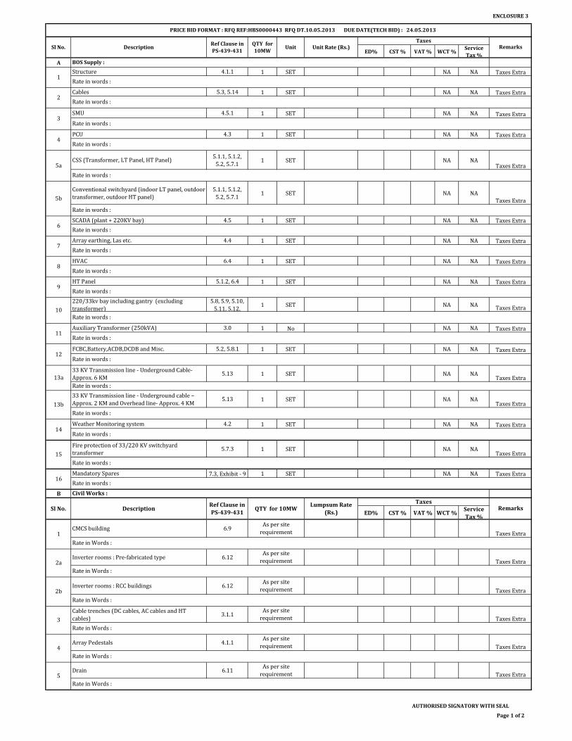
ENCLOSURE 3
ED% CST % VAT % WCT %Service
Tax %
A
Structure 4.1.1 1 SET NA NA Taxes Extra
Cables 5.3, 5.14 1 SET NA NA Taxes Extra
SMU 4.5.1 1 SET NA NA Taxes Extra
PCU 4.3 1 SET NA NA Taxes Extra
CSS (Transformer, LT Panel, HT Panel)5.1.1, 5.1.2,
5.2, 5.7.11 SET NA NA
Taxes Extra
Conventional switchyard (indoor LT panel, outdoor
transformer, outdoor HT panel)
5.1.1, 5.1.2,
5.2, 5.7.11 SET NA NA
Taxes Extra
SCADA (plant + 220KV bay) 4.5 1 SET NA NA Taxes Extra
Array earthing, Las etc. 4.4 1 SET NA NA Taxes Extra
HVAC 6.4 1 SET NA NA Taxes Extra
HT Panel 5.1.2, 6.4 1 SET NA NA Taxes Extra
220/33kv bay including gantry (excluding
transformer)
5.8, 5.9, 5.10,
5.11, 5.12, 1 SET NA NA Taxes Extra
Auxiliary Transformer (250kVA) 3.0 1 No NA NA Taxes Extra
FCBC,Battery,ACDB,DCDB and Misc. 5.2, 5.8.1 1 SET NA NA Taxes Extra
33 KV Transmission line - Underground Cable-
Approx. 6 KM5.13 1 SET NA NA
Taxes Extra
33 KV Transmission line - Underground cable –
Approx. 2 KM and Overhead line- Approx. 4 KM5.13 1 SET NA NA
Taxes Extra
Weather Monitoring system 4.2 1 SET NA NA Taxes Extra
Fire protection of 33/220 KV switchyard
transformer5.7.3 1 SET NA NA
Taxes Extra
Mandatory Spares 7.3, Exhibit - 9 1 SET NA NA Taxes Extra
B
ED% CST % VAT % WCT %Service
Tax %
CMCS building 6.9Taxes Extra
Inverter rooms : Pre-fabricated type 6.12Taxes Extra
Inverter rooms : RCC buildings 6.12Taxes Extra
Cable trenches (DC cables, AC cables and HT
cables)3.1.1
Taxes Extra
Array Pedestals 4.1.1Taxes Extra
Drain 6.11Taxes Extra
AUTHORISED SIGNATORY WITH SEAL
Page 1 of 2
PRICE BID FORMAT : RFQ REF:HBS0000443 RFQ DT.10.05.2013 DUE DATE(TECH BID) : 24.05.2013
Rate in words :
Rate in words :
Rate in words :
Rate in words :
Rate in words :
Rate in words :
Rate in words :
Rate in words :
UnitTaxes
RemarksUnit Rate (Rs.)
BOS Supply :
1
8
2
3
4
5a
6
7
Sl No. Description
Rate in words :
Rate in Words :
Rate in Words :
Civil Works :
14
As per site
requirement1
Rate in Words :
2a
3
4
5
Ref Clause in
PS-439-431
QTY for
10MW
9
10
11
12
Rate in words :
Rate in words :
Rate in words :
Rate in words :
As per site
requirement
As per site
requirement
Rate in Words :
Rate in Words :
2b
As per site
requirement
Rate in Words :
Sl No. DescriptionRef Clause in
PS-439-431
Lumpsum Rate
(Rs.)
Taxes
5b
Rate in words :
Rate in words :
13a
Rate in words :
15
Rate in words :
16Rate in words :
13b
RemarksQTY for 10MW
As per site
requirement
As per site
requirement
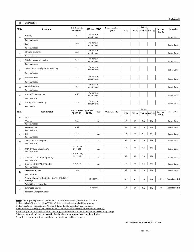
Enclosure 3
B
ED% CST % VAT % WCT %Service
Tax %
Pathway 6.7Taxes Extra
Road 6.7 Taxes Extra
HT panel platform 3.1.1Taxes Extra
CSS platforms with fencing 3.1.1Taxes Extra
Conventional switchyard with fencing 3.1.1Taxes Extra
Approach Road 6.7Taxes Extra
LA, Earthing etc. 5.4Taxes Extra
Rate in Words :
Module Water washing 6.10Taxes Extra
Fencing of 33KV switchyard 6.9Taxes Extra
ED% CST % VAT % WCT %Service
Tax %
C
PV Array 4.1.1 1 AU NA NA NA NA Taxes Extra
Inverter Room 6.12 1 AU NA NA NA NA Taxes Extra
CSS 5.1.1 1 AU NA NA NA NA Taxes Extra
Conventional switchyard 5.1.1 1 AU NA NA NA NA Taxes Extra
33 kV HT Yard Equipment’s 5.8, 5.9, 5.10,
5.11, 5.12 1 AUNA NA NA NA
Taxes Extra
220 kV HT Yard Including Gantry
5.8, 5.9, 5.10,
5.11, 5.12,
5.151 AU
NA NA NA NATaxes Extra
Cable Line DC, LTAC, HT & EHT 5.3, 5.14 1 AU NA NA NA NA Taxes Extra
**O&M for 1 year 8.0 4 AU NA NA NA NA Taxes Extra
Freight Charge (including Service Tax @ 3.09% )
on FreightNA NA NA NA 3.09% Taxes Included
Insurance Charge NA NA NA NA NA Taxes Included
2. Please indicate % of taxes : ED,VAT/CST, WCT,Service tax clearly applicable as on date.
3. Please quote only the basic rates.All taxes & duties shall be quoted extra as applicable.
4. The percentage of Supply,Civil Works, I&C and O&M values shall be in the ratio as indicated in RFQ.
5. For Supply & I&C, 1 SET/AU refers to the total qty for 10MW and **For O&M, the rate will be quarterly charge.
6. Contractor shall indicate the quantity for the above requirement based on their design.
7. Use this format for quoting ( reproducing on your letter head is acceptable).
AUTHORISED SIGNATORY WITH SEAL
Page 2 of 2
As per site
requirement
9b
As per site
requirement
Rate in Words :
Rate in Words :
Rate in Words :
Rate in Words :
Rate in Words :
12
Ref Clause in
PS-439-431
I&C :
As per site
requirement
Sl No. DESCRIPTIONQTY for
10MW
11
Rate in Words :
Remarks
10
As per site
requirement
Civil Works :
Sl No.
Rate in Words :
Rate in words :
Freight Charge in words :
Insurance Charge in words :
1
8
6
7
As per site
requirement
As per site
requirement
Rate in Words :
Rate in Words :
Rate in Words :
As per site
requirement
E
F
Rate in Words :
NOTE: 1.Your quoted prices shall be on “Free On Road” basis to site (Unchahar,Raibareli-UP).
LUMPSUM
LUMPSUM
As per site
requirement9aRate in Words :
Rate in Words :
13
As per site
requirementRate in Words :
3bRate in Words :
Unit
2
3a
4
5
6
D
Unit Rate (Rs.)Taxes
DescriptionRef Clause in
PS-439-431QTY for 10MW
Lumpsum Rate
(Rs.)
TaxesRemarks
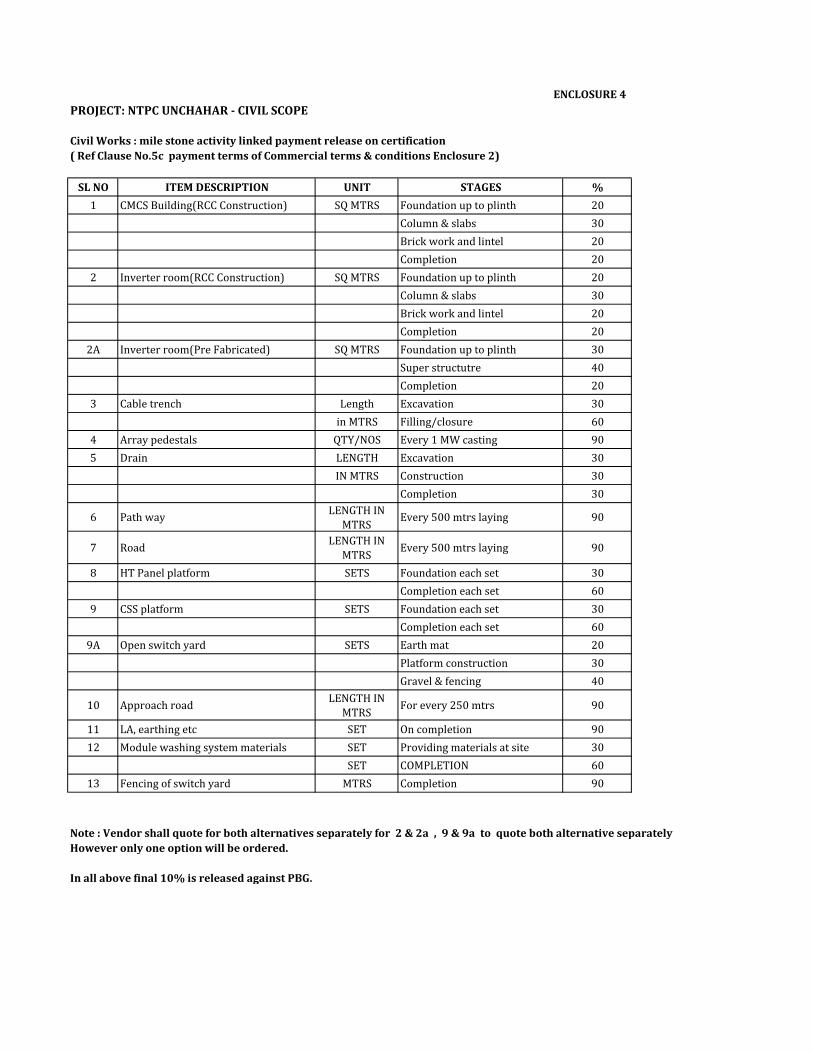
PROJECT: NTPC UNCHAHAR - CIVIL SCOPE
Civil Works : mile stone activity linked payment release on certification
( Ref Clause No.5c payment terms of Commercial terms & conditions Enclosure 2)
SL NO ITEM DESCRIPTION UNIT STAGES %
1 CMCS Building(RCC Construction) SQ MTRS Foundation up to plinth 20
Column & slabs 30
Brick work and lintel 20
Completion 20
2 Inverter room(RCC Construction) SQ MTRS Foundation up to plinth 20
Column & slabs 30
Brick work and lintel 20
Completion 20
2A Inverter room(Pre Fabricated) SQ MTRS Foundation up to plinth 30
Super structutre 40
Completion 20
3 Cable trench Length Excavation 30
in MTRS Filling/closure 60
4 Array pedestals QTY/NOS Every 1 MW casting 90
5 Drain LENGTH Excavation 30
IN MTRS Construction 30
Completion 30
6 Path wayLENGTH IN
MTRSEvery 500 mtrs laying 90
7 RoadLENGTH IN
MTRSEvery 500 mtrs laying 90
8 HT Panel platform SETS Foundation each set 30
Completion each set 60
9 CSS platform SETS Foundation each set 30
Completion each set 60
9A Open switch yard SETS Earth mat 20
Platform construction 30
Gravel & fencing 40
10 Approach roadLENGTH IN
MTRSFor every 250 mtrs 90
11 LA, earthing etc SET On completion 90
12 Module washing system materials SET Providing materials at site 30
SET COMPLETION 60
13 Fencing of switch yard MTRS Completion 90
Note : Vendor shall quote for both alternatives separately for 2 & 2a , 9 & 9a to quote both alternative separately
However only one option will be ordered.
In all above final 10% is released against PBG.
ENCLOSURE 4
r
I EnounlrFoolesl 10, ouoralioi luFola) Any Purchase Ode, reslrlnq r,on rhs enqu.y shall be qovEr.ad bv these senerar rarms and
BanoaLore 560026 therenafier retened ro as
bl Any ol rhe rems aid condil supD er, sha be e& LcLlLv merroned n re. ;'6n orh'ws. r!
4 rimmdcrms trd dond Liom arc oriered by supp er BNEL EDN shalnDr bo govered bv su.h remsandcoidtons !ness 1 sdEeedan.r ncorporardd ilhoFurchaseorderoJBHELEDN
d) Any d€viaron lo rie iems and raron bv supp er n rcspDnse to rhs
o on. o, . BFC D\r o. o. .d oo.op o EqFt FDNB'l.DNee'"
o" " ..o;., .o, a. "
Ds Rrr ltDNrlND/rro 0l
Enquiry-GeneralTermsand Conditions (hdisenous Purchase)
olrd(mha b.*bm ed nas iqu ry number and dts dale (llil
"" "id.crhcd,c, r,p:nd rme nd.arsdLnRFob) rr th6 quolalron is ro be sulrmlied in rrc parl lri.r (lechno commerc a and prlce bds), lrie echno
Fmme[abjdsha."'"-mle"'oo,e""'
enqwy numlior anr due date 01 oFeiin!lc) oloraron lrrolgh rax / ema ro rhe specrc rai number and ema
.". " ; e.q..* *!i m. *.,"
"ts..D1."P) L3equoa on trLlUe rcle .d
r lh'; is inv d rlercn.e , d sc,epm.v in drds quored 1o, per u r and I6,^,.b-"i bfrs. the lo** or re drcs Lreneri.ia ToBHELEDN
i AI rhe 16ndere.s o, rhetr iL, idsed repre$nialve (\uth thor
Fir.DNfi"cJa
" " .i"au ' eo .*
s Packino Goods musrbe adaq
" -";., """," r" o.m"oe .' " o o " ", o.q r,-" od
o*,;bn --rd e b;*d ;. d
s BHEL EDi! do6 nd bnd GcL
-u5 _t; /,'/ / t Enqutrv-uenerar rermsand
D!! Pr FnN rilD ENa 0L
9 Trre q!.nllv . ea.f, rcm lo be purchased nay 'ary
ircn rrla ry enqu rcd acoodino 10 admrr6rtu remeni ; I 2 tma or prac nq rhe Furcrrasd order ou.n y d scounl ir My. shou d bi;edoned
,,6.- .D: o, .: 1,", ,o
srns rorruru.e snqu ry ar rlre so e discrelon or BHEL EDN.e v€ry lnumber or ddys or lvecks)b
D avo d ouotatons wrh deiver
rrere m3re a s provded by BHEL EDN bankquarrnree as nd.ale.i i enqu ry/ Fo sha bo 0rdvided bysupprjer J p
16, &!dlr: Fairlc b app y wrh orddrw, make rbe supDlier iabero(ha[ percen0 perweek ar the ba
underiverod quantiry. subjecr ro aonosl quoralion ony amon,t rhe I
o" -o DEi. DNr on;
Advance paynenr or'hrand Loror
DrcslqUDlal^r'olion-a'drcemenl
ror non aoreomen o rems or pavmonLor l00:; pavmenl wirr 30 days credllr rhe quoralioi is Paymenlhrouoh
rlhequoraror s rolaqrecaber re qnolaLoi s 5eo ma: hum aqreed : Loading rjdror 5r.ftroquolaron sorhernrailrieabcve Loadnglactorll0% quoledmax%)
condiiions (lndioenous
cl Fornon aoreemen!on.Jc ve a
D ." : o"" "o ... , o" "..o, or ..".o" .o"oo".".." o ",;"b,supp er rhen Deivery dale ar BNE
ter tr.arspon:ion by sHEL EDNt
re r b.lhe rareren.eL EDN berore dosparch, rhen
irre i.,r..r0n ra dare 3v.n lrt supp er rv berhe r.lorence.
roi il s[pp ers wc ssrequrederherbySNELEDNand/oIbyr,,..r$0r0r or BHEL EDN. srpDr.r srJ prDVde necassary assslanceto Lnspecloi
xr.aica i the quolaron rnd n lhe purhase of,1tr, oi B|EL EDN ony 10 bef:r,sad 'j rrE,e s .fy.rraig. l
LD,22 slppla s sals rair ECCI VA eiroied quoralon.23 Ary nspur: ac nil crr or tf s
a rEL EDN or sny olrrer.:r.sr nosha bFr:a aidaind0soi r.e pa r a casessha beBanoarord
rq! ry es n he cou I or tungaoreoiLy
of 7 1
INTEGRITY PACT
Between
Bharat Heavy Electricals Ltd. (BHEL), a company registered under the Companies Act 1956 and
having its registered office at “BHEL House”, Siri Fort, New Delhi – 110049 (India) hereinafter
referred to as “The Principal”, which expression unless repugnant to the context or meaning
hereof shall include its successors or assigns of the ONE PART
and
______________________________________________________________, (description of the
party along with address), hereinafter referred to as “The Bidder/ Contractor” which expression
unless repugnant to the context or meaning hereof shall include its successors or assigns of the
OTHER PART
Preamble
The Principal intends to award, under laid-down organizational procedures, contract/s for
______________________________________________________________________________
______________________________________________________________________________
____________________________________________. The Principal values full compliance
with all relevant laws of the land, rules and regulations, and the principles of economic use of
resources, and of fairness and transparency in its relations with its Bidder(s)/ Contractor(s).
In order to achieve these goals, the Principal will appoint Independent External Monitor(s), who
will monitor the tender process and the execution of the contract for compliance with the
principles mentioned above.

of 7 2
Section 1 – Commitments of the Principal
1.1 The Principal commits itself to take all measures necessary to prevent corruption and to
observe the following principles:-
1.1.1 No employee of the Principal, personally or through family members, will in
connection with the tender for, or the execution of a contract, demand, take a promise
for or accept, for self or third person, any material or immaterial benefit which the
person is not legally entitled to.
1.1.2 The Principal will, during the tender process treat all Bidder(s) with equity and reason.
The Principal will in particular, before and during the tender process, provide to all
Bidder(s) the same information and will not provide to any Bidder(s) confidential /
additional information through which the Bidder(s) could obtain an advantage in
relation to the tender process or the contract execution.
1.1.3 The Principal will exclude from the process all known prejudiced persons.
1.2 If the Principal obtains information on the conduct of any of its employees which is a penal
offence under the Indian Penal Code 1860 and Prevention of Corruption Act 1988 or any
other statutory penal enactment, or if there be a substantive suspicion in this regard, the
Principal will inform its Vigilance Office and in addition can initiate disciplinary actions.
Section 2 – Commitments of the Bidder(s)/ Contractor(s)
2.1 The Bidder(s)/ Contractor(s) commit himself to take all measures necessary to prevent
corruption. He commits himself to observe the following principles during his participation
in the tender process and during the contract execution.
2.1.1 The Bidder(s)/ Contractor(s) will not, directly or through any other person or firm,
offer, promise or give to the Principal or to any of the Principal’s employees involved
in the tender process or the execution of the contract or to any third person any
material, immaterial or any other benefit which he / she is not legally entitled to, in
of 7 3
order to obtain in exchange any advantage of any kind whatsoever during the tender
process or during the execution of the contract.
2.1.2 The Bidder(s)/ Contractor(s) will not enter with other Bidder(s) into any illegal or
undisclosed agreement or understanding, whether formal or informal. This applies in
particular to prices, specifications, certifications, subsidiary contracts, submission or
non-submission of bids or any other actions to restrict competitiveness or to introduce
cartelization in the bidding process.
2.1.3 The Bidder(s)/ Contractor(s) will not commit any penal offence under the relevant IPC/
PC Act; further the Bidder(s)/ Contractor(s) will not use improperly, for purposes of
competition or personal gain, or pass on to others, any information or document
provided by the Principal as part of the business relationship, regarding plans, technical
proposals and business details, including information contained or transmitted
electronically.
2.1.4 The Bidder(s)/ Contractor(s) will, when presenting his bid, disclose any and all
payments he has made, and is committed to or intends to make to agents, brokers or any
other intermediaries in connection with the award of the contract.
2.2 The Bidder(s)/ Contractor(s) will not instigate third persons to commit offences outlined
above or be an accessory to such offences.
Section 3 – Disqualification from tender process and exclusion from future
contracts
If the Bidder(s)/ Contractor(s), before award or during execution has committed a transgression
through a violation of Section 2 above, or acts in any other manner such as to put his reliability
or credibility in question, the Principal is entitled to disqualify the Bidders(s)/ Contractor(s) from
the tender process or take action as per the separate “Guidelines for Suspension of Business
Dealings with Suppliers/ Contractors” framed by the Principal.
of 7 4
Section 4 – Compensation for Damages
4.1 If the Principal has disqualified the Bidder(s) from the tender process prior to the award
according to Section 3, the Principal is entitled to demand and recover the damages
equivalent to Earnest Money Deposit/ Bid Security.
4.2 If the Principal has terminated the contract according to Section 3, or if the Principal is
entitled to terminate the contract according to section 3, the Principal shall be entitled to
demand and recover from the Contractor liquidated damages equivalent to 5% of the
contract value or the amount equivalent to Security Deposit/Performance Bank Guarantee,
whichever is higher.
Section 5 – Previous Transgression
5.1 The Bidder declares that no previous transgressions occurred in the last 3 years with any
other company in any country conforming to the anti-corruption approach or with any other
Public Sector Enterprise in India that could justify his exclusion from the tender process.
5.2 If the Bidder makes incorrect statement on this subject, he can be disqualified from the
tender process or the contract, if already awarded, can be terminated for such reason.
Section 6 – Equal treatment of all Bidders/ Contractors/ Sub-contractors
6.1 The Bidder(s)/ Contractor(s) undertake(s) to demand from his sub-contractors a
commitment consistent with this Integrity Pact. This commitment shall be taken only from
those sub-contractors whose contract value is more than 20% of Bidder’s/ Contractor’s
contract value with the Principal.
6.2 The Principal will enter into agreements with identical conditions as this one with all
Bidders and Contractors.
6.3 The Principal will disqualify from the tender process all bidders who do not sign this pact
or violate its provisions.

of 7 5
Section 7 – Criminal Charges against violating Bidders/ Contractors /Sub-
contractors
If the Principal obtains knowledge of conduct of a Bidder, Contractor or Subcontractor, or of an
employee or a representative or an associate of a Bidder, Contractor or Subcontractor which
constitutes corruption, or if the Principal has substantive suspicion in this regard, the Principal
will inform the Vigilance Office.
Section 8 –Independent External Monitor(s)
8.1 The Principal appoints competent and credible Independent External Monitor for this Pact.
The task of the Monitor is to review independently and objectively, whether and to what
extent the parties comply with the obligations under this agreement.
8.2 The Monitor is not subject to instructions by the representatives of the parties and performs
his functions neutrally and independently. He reports to the CMD, BHEL.
8.3 The Bidder(s)/ Contractor(s) accepts that the Monitor has the right to access without
restriction to all contract documentation of the Principal including that provided by the
Bidder(s)/ Contractor(s). The Bidder(s)/ Contractor(s) will grant the monitor, upon his
request and demonstration of a valid interest, unrestricted and unconditional access to his
contract documentation. The same is applicable to Sub-contractor(s). The Monitor is under
contractual obligation to treat the information and documents of the Bidder(s)/
Contractor(s) / Sub-contractor(s) with confidentiality.
8.4 The Principal will provide to the Monitor sufficient information about all meetings among
the parties related to the contract provided such meetings could have an impact on the
contractual relations between the Principal and the Contractor. The parties offer to the
Monitor the option to participate in such meetings.
8.5 As soon as the Monitor notices, or believes to notice, a violation of this agreement, he will
so inform the Management of the Principal and request the Management to discontinue or

of 7 6
take corrective action, or heal the situation, or to take other relevant action. The Monitor
can in this regard submit non-binding recommendations. Beyond this, the Monitor has no
right to demand from the parties that they act in a specific manner, refrain from action or
tolerate action.
8.6 The Monitor will submit a written report to the CMD, BHEL within 8 to 10 weeks from the
date of reference or intimation to him by the Principal and, should the occasion arise,
submit proposals for correcting problematic situations.
8.7 The CMD, BHEL shall decide the compensation to be paid to the Monitor and its terms and
conditions.
8.8 If the Monitor has reported to the CMD, BHEL, a substantiated suspicion of an offence
under relevant IPC / PC Act, and the CMD, BHEL has not, within reasonable time, taken
visible action to proceed against such offence or reported it to the Vigilance Office, the
Monitor may also transmit this information directly to the Central Vigilance
Commissioner, Government of India.
8.9 The number of Independent External Monitor(s) shall be decided by the CMD, BHEL.
8.10 The word ‘Monitor’ would include both singular and plural.
Section 9 – Pact Duration
9.1 This Pact begins when both parties have legally signed it. It expires for the Contractor 12
months after the last payment under the respective contract and for all other Bidders 6
months after the contract has been awarded.
9.2 If any claim is made / lodged during this time, the same shall be binding and continue to be
valid despite the lapse of this pact as specified as above, unless it is discharged/ determined
by the CMD, BHEL.

of 7 7
Section 10 – Other Provisions
10.1 This agreement is subject to Indian Laws and jurisdiction shall be registered office of the
Principal, i.e. New Delhi.
10.2 Changes and supplements as well as termination notices need to be made in writing. Side
agreements have not been made.
10.3 If the Contractor is a partnership or a consortium, this agreement must be signed by all
partners or consortium members.
10.4 Should one or several provisions of this agreement turn out to be invalid, the remainder of
this agreement remains valid. In this case, the parties will strive to come to an agreement to
their original intentions.
10.5 Only those bidders/ contractors who have entered into this agreement with the Principal
would be competent to participate in the bidding. In other words, entering into this
agreement would be a preliminary qualification.
------------------------------------ -----------------------------------
For & On behalf of the Principal For & On behalf of the Bidder/ Contractor
(Office Seal) (Office Seal)
Place----------------------
Date-----------------------
Witness: ____________________ Witness: _______________________
(Name & Address) ____________ (Name & Address)________________
____________________________ _______________________________
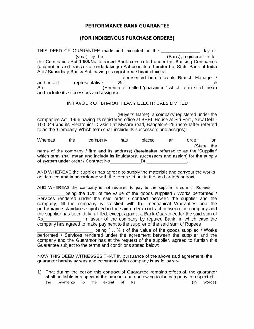
PERFORMANCE BANK GUARANTEE
(FOR INDIGENOUS PURCHASE ORDERS) THIS DEED OF GUARANTEE made and executed on the ________________ day of _______________(year), by the ________________________ (Bank), registered under the Companies Act 1956/Nationalised Bank constituted under the Banking Companies (acquisition and transfer of undertakings) Act constituted under the State Bank of India Act / Subsidiary Banks Act, having its registered / head office at ________________________________ represented herein by its Branch Manager / authorised representative Sri. _______________________ & Sri._______________________(Hereinafter called 'guarantor ' which term shall mean and include its successors and assigns)
IN FAVOUR OF BHARAT HEAVY ELECTRICALS LIMITED
_______________________________ (Buyer's Name), a company registered under the companies Act, 1956 having its registered office at BHEL House at Siri Fort , New Delhi-100 049 and its Electronics Division at Mysore road, Bangalore-26 (hereinafter referred to as the 'Company' Which term shall include its successors and assigns): Whereas the company has placed an order on ____________________________________________________________ (State the name of the company / firm and its address) (hereinafter referred to as the 'Supplier' which term shall mean and include its liquidators, successors and assign) for the supply of system under order / Contract No____________Dt ________________.
AND WHEREAS the supplier has agreed to supply the materials and carryout the works as detailed and in accordance with the terms set out in the said order/contract. AND WHEREAS the company is not required to pay to the supplier a sum of Rupees ___________being the 10% of the value of the goods supplied / Works performed / Services rendered under the said order / contract between the supplier and the company, till the company is satisfied with the mechanical Warranties and the performance standards stipulated in the said order / contract between the company and the supplier has been duly fulfilled, except against a Bank Guarantee for the said sum of Rs_______________ in favour of the company by reputed Bank, in which case the company has agreed to make payment to the supplier of the said sum of Rupees ______________________ being ( …% ) of the value of the goods supplied / Works performed / Services rendered under the agreement between the supplier and the company and the Guarantor has at the request of the supplier, agreed to furnish this Guarantee subject to the terms and conditions stated below:
NOW THIS DEED WITNESSES THAT IN pursuance of the above said agreement, the guarantor hereby agrees and covenants With company is as follows :-
1) That during the period this contract of Guarantee remains effectual, the guarantor
shall be liable in respect of the amount due and owing to the company in respect of the payments to the extent of Rs _______________ (in words)
_________________________________________________________ against any loss or damage caused to or suffered by the company by reasons of any breach of the terms of the said order / contract / Agreement by the supplier.
2) The Guarantor hereby undertakes to pay the amounts due and payable under this
guarantee without any demur, merely on demand from the company intimating that the amount claimed is due by way of loss or damage caused to or suffered or would be caused or suffered by the supplier of any terms contained in the said order / contract. Any such demand made on the guarantor shall be conclusive as regards the amount due and payable by the Guarantor irrespective of the fact whether the Contractor / supplier admits or denies.
3) The Guarantor further agrees that the agreement herein contained shall remain in force and effect till all the supplies to be made / Works to be performed / Services to be rendered under the said order / contract / agreement are completed to the entire satisfaction of the company or till company certifies that the terms and conditions of the said order / contract / agreement have been fully and properly carried out by the said supplier and accordingly discharges the Guarantee. Unless a demand or claim under this guarantee is made on the guarantor in writing on or before the expiry of claim period indicated in clause 6 below , the guarantor shall be discharged from all the liability under this guarantee thereafter.
4) The guarantor further agrees with the company that the company shall have the fullest liberty without the consent of the guarantor and without effecting in any manner the obligations of the guarantor hereunder to vary any of the terms of the said order / contract / agreement or extend the time of performance by the said supplier from time to time or refrain from exercising the power exercisable by the company against the said supplier or to forebear or omit to enforce any of the terms and conditions relating to the said order / contract / agreement, and the guarantor shall not be relieved of its liability in whole or in part , by reason of any act, commission or forbearance on the part of the company or by reason of any such variation, or extension being granted to the said supplier or by reason of any such matter or thing whatsoever which under the law relating to sureties would but for this provision have effect of so relieving the guarantor.
5) The guarantor undertakes not to revoke this guarantee during its currency except with the
previous consent of the company in writing.
6) Notwithstanding anything herein above contained, the liability of the guarantor under these presents is restricted to Rs___________________. The guarantee shall be in force till its expiry on __________________ unless a demand is made on the guarantor within SIX months from the date of expiry, all the liability of the guarantor under this guarantee shall stand fully discharged. The decision of the claimant in regard to breach of contract is final and binding on the Bank.
IN WITNESS whereof, the guarantor, acting through it authorised representative has executed this deed of Guarantee on the day, month and year first above written.
(Seal of the Bank to be affixed ) WITNESS
1. 2.
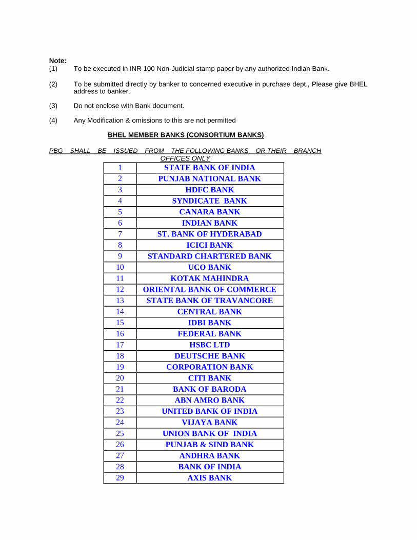
Note: (1) To be executed in INR 100 Non-Judicial stamp paper by any authorized Indian Bank.
(2) To be submitted directly by banker to concerned executive in purchase dept., Please give BHEL
address to banker. (3) Do not enclose with Bank document. (4) Any Modification & omissions to this are not permitted
BHEL MEMBER BANKS (CONSORTIUM BANKS) PBG SHALL BE ISSUED FROM THE FOLLOWING BANKS OR THEIR BRANCH
OFFICES ONLY 1 STATE BANK OF INDIA
2 PUNJAB NATIONAL BANK
3 HDFC BANK
4 SYNDICATE BANK
5 CANARA BANK
6 INDIAN BANK
7 ST. BANK OF HYDERABAD
8 ICICI BANK
9 STANDARD CHARTERED BANK
10 UCO BANK
11 KOTAK MAHINDRA
12 ORIENTAL BANK OF COMMERCE
13 STATE BANK OF TRAVANCORE
14 CENTRAL BANK
15 IDBI BANK
16 FEDERAL BANK
17 HSBC LTD
18 DEUTSCHE BANK
19 CORPORATION BANK
20 CITI BANK
21 BANK OF BARODA
22 ABN AMRO BANK
23 UNITED BANK OF INDIA
24 VIJAYA BANK
25 UNION BANK OF INDIA
26 PUNJAB & SIND BANK
27 ANDHRA BANK
28 BANK OF INDIA
29 AXIS BANK