Embed Size (px)
Citation preview

© Copyright by BIFFI Italia. All rights reserved.BIFFI is a subsidiary of Keystone International, Inc.
Integral Starter IS 2000instruction and operating manual
BIFFC-0031-EN-9602Contents may change without notice.
INSTRUCTION AND OPERATING MANUALFOR “IS 2000” AND ACCESSORIES
INDEX
CHAPTER 1 GeneralDescription andAccessoriespage 3
CHAPTER 2 Storage andPre-Installationpage 7
CHAPTER 3 Installationpage 7
CHAPTER 4 Setting ofAccessoriespage 8
CHAPTER 5 Maintenancepage 13
CHAPTER 6 Trouble-Shootingpage 14
CHAPTER 7 RecommendedSpare Partspage 15
IMPORTANT: this manual must beused together with the manual relevantto the actuator to which the IS 2000is fitted.
2 © Copyright by BIFFI Italia. All rights reserved.BIFFI is a subsidiary of Keystone International, Inc.
Integral Starter IS 2000instruction and operating manual
BIFFC-0031-EN-9602 Contents may change without notice.
DETAILED INDEX
CHAPTER 1, page 3
General Description andAccessories
1) Identification of the main parts
2) General description
3) IS 2000 standard functions
4) Accessories and their functions
CHAPTER 2, page 7
Storage and Pre-Installation
1) Tests to be carried out on receipt ofthe actuator
2) Storage procedure
CHAPTER 3, page 7
Installation
CHAPTER 4, page 8
Setting of Accessories
1) IS 2000/ESD: setting of ESD functionand phase discrimination
2) IS 2000/RBS: calibration of theelectronic cards
3) IS 2000/TMR and IS 2000/TWC:calibration of the electronic card
4) 4 - position local selector
CHAPTER 5, page 13Maintenance
CHAPTER 6, page 14
Trouble-Shooting
1) The actuator does not workelectrically
2) The actuator does not start onremote control
3) The actuator does not start onlocal control
4) The actuator does not workstep-by-step (for IS 2000/TMR)
CHAPTER 7, page15
Recommended Spare Parts
1) Commissioning spare parts kits
2) Recommended spare parts fortwo years’ operation
NOTES:BIFFI Italia has taken every care in collecting and verifying the documentation contained in this instruction and operating manual.Nevertheless Biffi Italia does not provide any guarantees for this instruction manual.BIFFI Italia will not be responsible for any mistakes contained in it or for any damage either accidental or due to the use of thismanual.The information herein contained is reserved property of BIFFI Italia and is subject to being modified without notice.
3© Copyright by BIFFI Italia. All rights reserved.BIFFI is a subsidiary of Keystone International, Inc.
Integral Starter IS 2000instruction and operating manual
BIFFC-0031-EN-9602Contents may change without notice. 3
CHAPTER 1
General Descriptionand Accessories
INDEX1) Identification of the main parts
2) General description
3) IS 2000 standard functions
4) Accessories and their functions
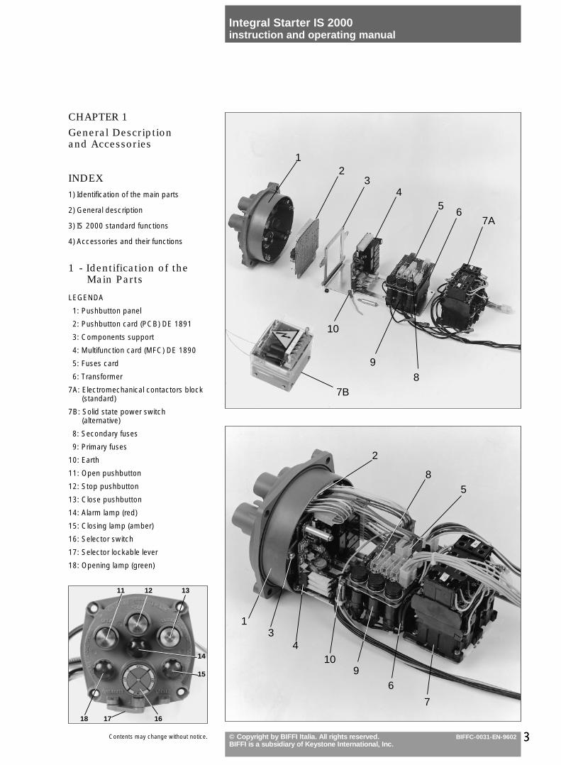
1 - Identification of theMain Parts
LEGENDA
1: Pushbutton panel
2: Pushbutton card (PCB) DE 1891
3: Components support
4: Multifunction card (MFC) DE 1890
5: Fuses card
6: Transformer
7A: Electromechanical contactors block(standard)
7B: Solid state power switch(alternative)
8: Secondary fuses
9: Primary fuses
10: Earth
11: Open pushbutton
12: Stop pushbutton
13: Close pushbutton
14: Alarm lamp (red)
15: Closing lamp (amber)
16: Selector switch
17: Selector lockable lever
18: Opening lamp (green)
1 2
34
56
7A
10
7B6
8
1 3
410
96
7
2
85
11 12 13
18 17 16
14
15
4 © Copyright by BIFFI Italia. All rights reserved.BIFFI is a subsidiary of Keystone International, Inc.
Integral Starter IS 2000instruction and operating manual
BIFFC-0031-EN-9602 Contents may change without notice.
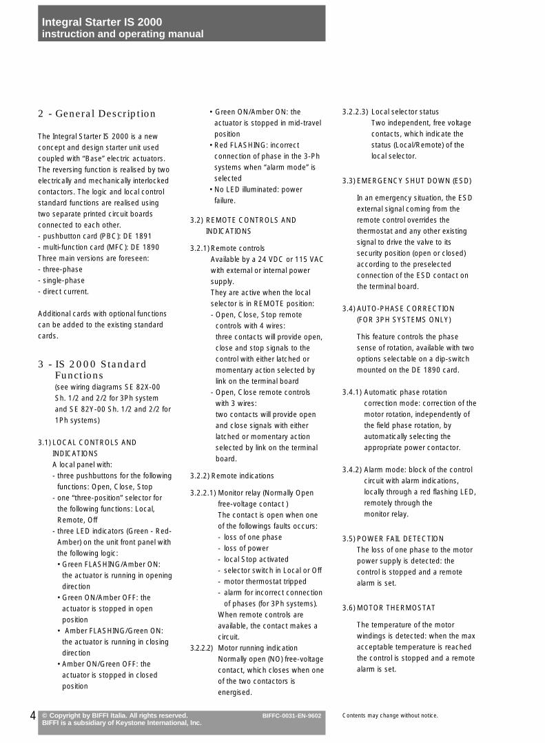
2 - General Description
The Integral Starter IS 2000 is a newconcept and design starter unit usedcoupled with “Base” electric actuators.The reversing function is realised by twoelectrically and mechanically interlockedcontactors. The logic and local controlstandard functions are realised usingtwo separate printed circuit boardsconnected to each other.- pushbutton card (PBC): DE 1891- multi-function card (MFC): DE 1890Three main versions are foreseen:- three-phase- single-phase- direct current.
Additional cards with optional functionscan be added to the existing standardcards.
3 - IS 2000 StandardFunctions(see wiring diagrams SE 82X-00Sh. 1/2 and 2/2 for 3Ph systemand SE 82Y-00 Sh. 1/2 and 2/2 for1Ph systems)
3.1) LOCAL CONTROLS ANDINDICATIONSA local panel with:- three pushbuttons for the following
functions: Open, Close, Stop- one “three-position” selector for
the following functions: Local,Remote, Off
- three LED indicators (Green - Red-Amber) on the unit front panel withthe following logic:•Green FLASHING/Amber ON:
the actuator is running in openingdirection
•Green ON/Amber OFF: theactuator is stopped in openposition
• Amber FLASHING/Green ON:the actuator is running in closingdirection
•Amber ON/Green OFF: theactuator is stopped in closedposition
• Green ON/Amber ON: theactuator is stopped in mid-travelposition
•Red FLASHING: incorrectconnection of phase in the 3-Phsystems when “alarm mode” isselected
•No LED illuminated: powerfailure.
3.2) REMOTE CONTROLS ANDINDICATIONS
3.2.1) Remote controlsAvailable by a 24 VDC or 115 VACwith external or internal powersupply.They are active when the localselector is in REMOTE position:- Open, Close, Stop remote
controls with 4 wires:three contacts will provide open,close and stop signals to thecontrol with either latched ormomentary action selected bylink on the terminal board
- Open, Close remote controlswith 3 wires:two contacts will provide open and close signals with eitherlatched or momentary actionselected by link on the terminalboard.
3.2.2) Remote indications
3.2.2.1) Monitor relay (Normally Open free-voltage contact )The contact is open when oneof the followings faults occurs:- loss of one phase- loss of power- local Stop activated- selector switch in Local or Off- motor thermostat tripped- alarm for incorrect connection
of phases (for 3Ph systems).When remote controls areavailable, the contact makes acircuit.
3.2.2.2) Motor running indicationNormally open (NO) free-voltagecontact, which closes when oneof the two contactors isenergised.
3.2.2.3) Local selector statusTwo independent, free voltagecontacts, which indicate thestatus (Local/Remote) of thelocal selector.
3.3) EMERGENCY SHUT DOWN (ESD)
In an emergency situation, the ESDexternal signal coming from theremote control overrides thethermostat and any other existingsignal to drive the valve to itssecurity position (open or closed)according to the preselectedconnection of the ESD contact onthe terminal board.
3.4) AUTO-PHASE CORRECTION(FOR 3PH SYSTEMS ONLY)
This feature controls the phasesense of rotation, available with twooptions selectable on a dip-switchmounted on the DE 1890 card.
3.4.1) Automatic phase rotationcorrection mode: correction of themotor rotation, independently ofthe field phase rotation, byautomatically selecting theappropriate power contactor.
3.4.2) Alarm mode: block of the controlcircuit with alarm indications,locally through a red flashing LED,remotely through themonitor relay.
3.5) POWER FAIL DETECTIONThe loss of one phase to the motorpower supply is detected: thecontrol is stopped and a remotealarm is set.
3.6) MOTOR THERMOSTAT
The temperature of the motorwindings is detected: when the maxacceptable temperature is reachedthe control is stopped and a remotealarm is set.
5© Copyright by BIFFI Italia. All rights reserved.BIFFI is a subsidiary of Keystone International, Inc.
Integral Starter IS 2000instruction and operating manual
BIFFC-0031-EN-9602Contents may change without notice.
4 - Accessories and theirFunctions
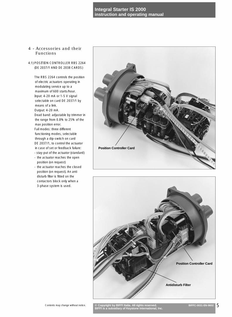
4.1) POSITION CONTROLLER RBS 2264(DE 2037/1 AND DE 2038 CARDS)
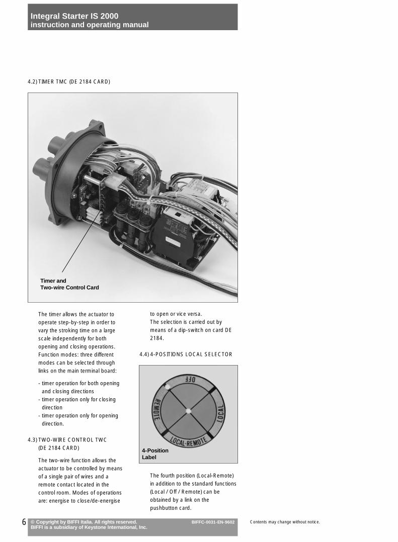
The RBS 2264 controls the positionof electric actuators operating inmodulating service up to amaximum of 600 starts/hour.Input: 4-20 mA or 1-5 V signalselectable on card DE 2037/1 bymeans of a link.Output: 4-20 mA.Dead band: adjustable by trimmer inthe range from 0.8% to 25% of themax position error.Fail modes: three differentfunctioning modes, selectablethrough a dip-switch on cardDE 2037/1, to control the actuatorin case of set or feedback failure:- stay-put of the actuator (standard)- the actuator reaches the open
position (on request)- the actuator reaches the closed
position (on request). An antidisturb filter is fitted on thecontactors block only when a3-phase system is used.
Position Controller Card
Antidisturb Filter
Position Controller Card
6 © Copyright by BIFFI Italia. All rights reserved.BIFFI is a subsidiary of Keystone International, Inc.
Integral Starter IS 2000instruction and operating manual
BIFFC-0031-EN-9602 Contents may change without notice.
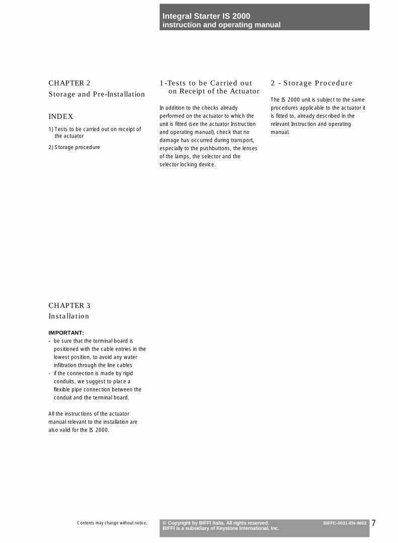
to open or vice versa.The selection is carried out bymeans of a dip-switch on card DE2184.
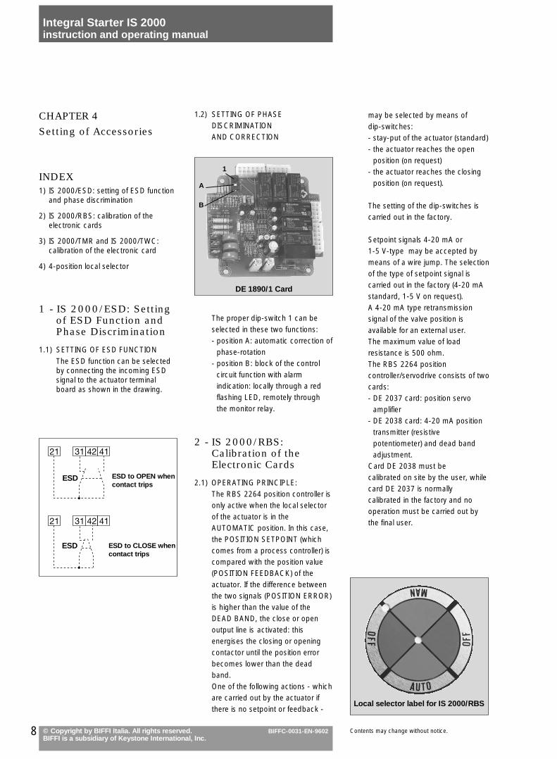
4.4) 4-POSITIONS LOCAL SELECTOR
The fourth position (Local-Remote)in addition to the standard functions(Local / Off / Remote) can beobtained by a link on thepushbutton card.
4.2) TIMER TMC (DE 2184 CARD)
The timer allows the actuator tooperate step-by-step in order tovary the stroking time on a largescale independently for bothopening and closing operations.Function modes: three differentmodes can be selected throughlinks on the main terminal board:
- timer operation for both openingand closing directions
- timer operation only for closingdirection
- timer operation only for openingdirection.
4.3) TWO-WIRE CONTROL TWC(DE 2184 CARD)
The two-wire function allows theactuator to be controlled by meansof a single pair of wires and aremote contact located in thecontrol room. Modes of operationsare: energise to close/de-energise
Timer andTwo-wire Control Card
4-PositionLabel
7© Copyright by BIFFI Italia. All rights reserved.BIFFI is a subsidiary of Keystone International, Inc.
Integral Starter IS 2000instruction and operating manual
BIFFC-0031-EN-9602Contents may change without notice.
CHAPTER 2
Storage and Pre-Installation
INDEX
1) Tests to be carried out on receipt ofthe actuator
2) Storage procedure
1-Tests to be Carried outon Receipt of the Actuator
In addition to the checks alreadyperformed on the actuator to which theunit is fitted (see the actuator Instructionand operating manual), check that nodamage has occurred during transport,especially to the pushbuttons, the lensesof the lamps, the selector and theselector locking device.
2 - Storage Procedure
The IS 2000 unit is subject to the sameprocedures applicable to the actuator itis fitted to, already described in therelevant Instruction and operatingmanual.
CHAPTER 3Installation
IMPORTANT:- be sure that the terminal board is
positioned with the cable entries in thelowest position, to avoid any waterinfiltration through the line cables
- if the connection is made by rigidconduits, we suggest to place aflexible pipe connection between theconduit and the terminal board.
All the instructions of the actuatormanual relevant to the installation arealso valid for the IS 2000.
1.2) SETTING OF PHASE DISCRIMINATIONAND CORRECTION
The proper dip-switch 1 can beselected in these two functions:- position A: automatic correction of
phase-rotation- position B: block of the control
circuit function with alarmindication: locally through a redflashing LED, remotely throughthe monitor relay.
2 - IS 2000/RBS:Calibration of theElectronic Cards
2.1) OPERATING PRINCIPLE:The RBS 2264 position controller isonly active when the local selectorof the actuator is in theAUTOMATIC position. In this case,the POSITION SETPOINT (whichcomes from a process controller) iscompared with the position value(POSITION FEEDBACK) of theactuator. If the difference betweenthe two signals (POSITION ERROR)is higher than the value of theDEAD BAND, the close or openoutput line is activated: thisenergises the closing or openingcontactor until the position errorbecomes lower than the deadband.One of the following actions - whichare carried out by the actuator ifthere is no setpoint or feedback -
CHAPTER 4
Setting of Accessories
INDEX1) IS 2000/ESD: setting of ESD function
and phase discrimination
2) IS 2000/RBS: calibration of theelectronic cards
3) IS 2000/TMR and IS 2000/TWC:calibration of the electronic card
4) 4-position local selector
1 - IS 2000/ESD: Settingof ESD Function andPhase Discrimination
1.1) SETTING OF ESD FUNCTIONThe ESD function can be selectedby connecting the incoming ESDsignal to the actuator terminalboard as shown in the drawing.
8 © Copyright by BIFFI Italia. All rights reserved.BIFFI is a subsidiary of Keystone International, Inc.
Integral Starter IS 2000instruction and operating manual
BIFFC-0031-EN-9602 Contents may change without notice.
may be selected by means ofdip-switches:- stay-put of the actuator (standard)- the actuator reaches the open
position (on request)- the actuator reaches the closing
position (on request).
The setting of the dip-switches iscarried out in the factory.
Setpoint signals 4-20 mA or1-5 V-type may be accepted bymeans of a wire jump. The selectionof the type of setpoint signal iscarried out in the factory (4-20 mAstandard, 1-5 V on request).A 4-20 mA type retransmissionsignal of the valve position isavailable for an external user.The maximum value of loadresistance is 500 ohm.The RBS 2264 positioncontroller/servodrive consists of twocards:- DE 2037 card: position servo
amplifier- DE 2038 card: 4-20 mA position
transmitter (resistivepotentiometer) and dead bandadjustment.
Card DE 2038 must becalibrated on site by the user, whilecard DE 2037 is normallycalibrated in the factory and nooperation must be carried out bythe final user.
ESD
ESD
ESD to OPEN whencontact trips
ESD to CLOSE whencontact trips
1
A
B
DE 1890/1 Card
Local selector label for IS 2000/RBS
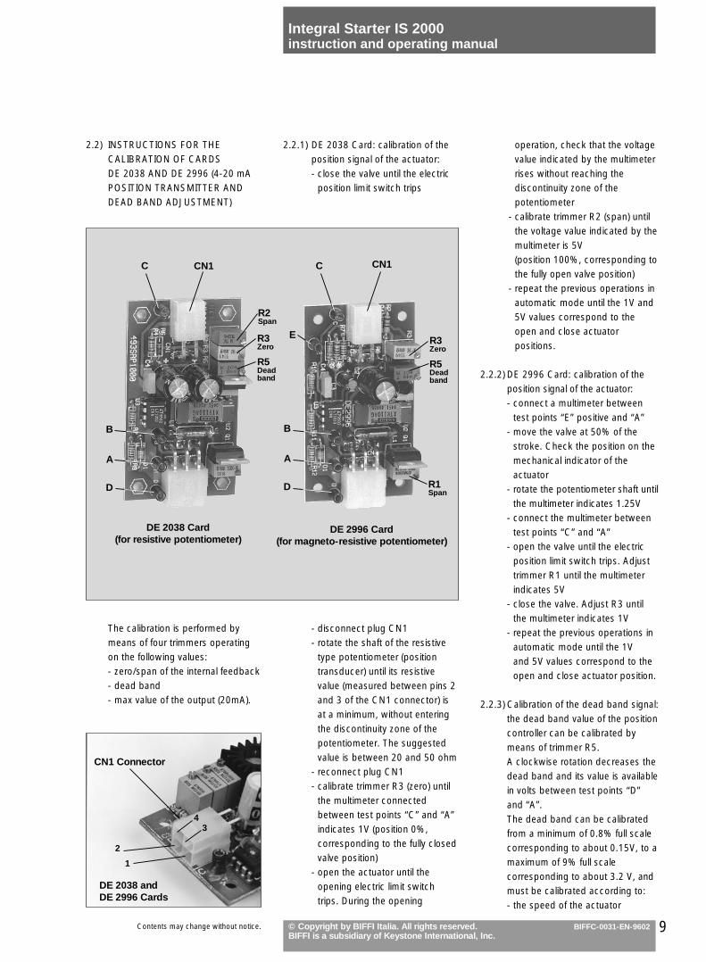
2.2.1) DE 2038 Card: calibration of theposition signal of the actuator:- close the valve until the electric
position limit switch trips
- disconnect plug CN1- rotate the shaft of the resistive
type potentiometer (positiontransducer) until its resistivevalue (measured between pins 2and 3 of the CN1 connector) isat a minimum, without enteringthe discontinuity zone of thepotentiometer. The suggestedvalue is between 20 and 50 ohm
- reconnect plug CN1- calibrate trimmer R3 (zero) until
the multimeter connectedbetween test points “C” and “A”indicates 1V (position 0%,corresponding to the fully closedvalve position)
- open the actuator until theopening electric limit switchtrips. During the opening
2.2) INSTRUCTIONS FOR THECALIBRATION OF CARDSDE 2038 AND DE 2996 (4-20 mAPOSITION TRANSMITTER ANDDEAD BAND ADJUSTMENT)
The calibration is performed bymeans of four trimmers operatingon the following values:- zero/span of the internal feedback- dead band- max value of the output (20mA).
9© Copyright by BIFFI Italia. All rights reserved.BIFFI is a subsidiary of Keystone International, Inc.
Integral Starter IS 2000instruction and operating manual
BIFFC-0031-EN-9602Contents may change without notice.
operation, check that the voltagevalue indicated by the multimeterrises without reaching thediscontinuity zone of thepotentiometer
- calibrate trimmer R2 (span) untilthe voltage value indicated by themultimeter is 5V(position 100%, corresponding tothe fully open valve position)
- repeat the previous operations inautomatic mode until the 1V and5V values correspond to theopen and close actuatorpositions.
2.2.2) DE 2996 Card: calibration of theposition signal of the actuator:- connect a multimeter between
test points “E” positive and “A”- move the valve at 50% of the
stroke. Check the position on themechanical indicator of theactuator
- rotate the potentiometer shaft untilthe multimeter indicates 1.25V
- connect the multimeter betweentest points “C” and “A”
- open the valve until the electricposition limit switch trips. Adjusttrimmer R1 until the multimeterindicates 5V
- close the valve. Adjust R3 untilthe multimeter indicates 1V
- repeat the previous operations inautomatic mode until the 1Vand 5V values correspond to theopen and close actuator position.
2.2.3) Calibration of the dead band signal:the dead band value of the positioncontroller can be calibrated bymeans of trimmer R5.A clockwise rotation decreases thedead band and its value is availablein volts between test points “D”and “A”.The dead band can be calibratedfrom a minimum of 0.8% full scalecorresponding to about 0.15V, to amaximum of 9% full scalecorresponding to about 3.2 V, andmust be calibrated according to:- the speed of the actuator
DE 2038 andDE 2996 Cards
1
CN1 Connector
CN1
2
34
DE 2038 Card(for resistive potentiometer)
DE 2996 Card(for magneto-resistive potentiometer)
C
ER3Zero
R5Deadband
B
A
D
B
A
D
R2Span
CN1C
R1Span
R3Zero
R5Deadband

2.3.1) Selection of the type of positionsetpoint:
- if the set is a 4-20 mA type, theJP1 jumper must be plugged in
- if the set is a 1-5V type, the JP1jumper must be removed.
- the necessary positioningaccuracy
- the allowable number of cyclesper hour.
2.2.4) Calibration of the end travelindication lamps signaling: aftercompleting the calibrationexplained at points 2.2.1), 2.2.2)and 2.2.3) check that theindication lamps at both end travelpositions are on. If they areflashing, proceed as follows:
Step A)A.1. connect a 4-20 mA (or 1- 5V)
signal generator to terminals43 and 44 of the actuator
A.2. connect a multimeterbetween test points “C” and“A” of DE 2038 card
A.3. switch the local selector to“Automatic” operation
A.4. set the signal generator to 4mA (or 1V)
A.5. when the actuator is in fullyclosed position, check theclosing lamp:- if it is on, go to the step B- if it flashes, decrease the
value measured by themultimeter of 20 mV, bymeans of trimmer R3
A.6. set the signal generatorto 12 mA (or 3V):the actuator must open
A.7. restart from point A.4.
Step B)B.1. set the signal generator
to 20 mA (or 5V)B.2. when the actuator is in fully
open position, check theopening lamp:- if it is on, go to step C- if it flashes, increase the
value measured by themultimeter of 20 mV, bymeans of:•trimmer R2 for DE 2038 card•trimmer R1 for DE 2996 card
B.3. set the signal generatorto 12 mA (or 3V):the actuator must close.
B.4. Restart from point B.1.
10 © Copyright by BIFFI Italia. All rights reserved.BIFFI is a subsidiary of Keystone International, Inc.
Integral Starter IS 2000instruction and operating manual
BIFFC-0031-EN-9602 Contents may change without notice.
Step C)C.1. repeat step A and step B until
the open and closed lampsare on, when the actuatorreaches the end travelpositions.
2.2.5) Test of the retransmission signal ofthe 4-20 mA valve position:- open the valve until it
automatically stops- connect a multimeter between
test points “C” and “A”: themeasured value should be 5V
- connect a milliammeter betweentest points “B” and “A”
- the indication of the milliammeterwill be 20 mA (max loadresistance = 500 ohm).
2.3) INSTRUCTIONS FOR THECALIBRATION OF CARD DE 2037/1(position servo amplifier)
These operations are normallycarried out in the factory.
T1
T2
U2U1
T3
JP1
J1
DE 2037/1 Card
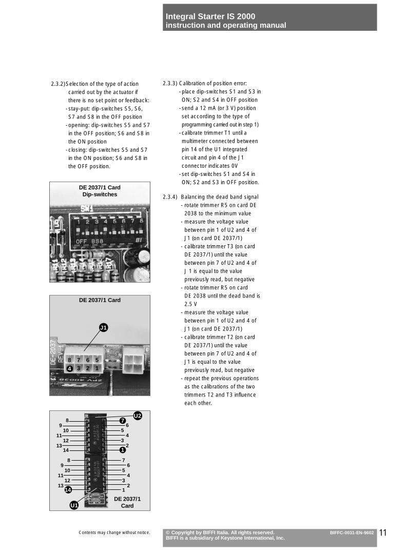
2.3.3) Calibration of position error:-place dip-switches S1 and S3 inON; S2 and S4 in OFF position
-send a 12 mA (or 3 V) positionset according to the type ofprogramming carried out in step 1)
-calibrate trimmer T1 until amultimeter connected betweenpin 14 of the U1 integratedcircuit and pin 4 of the J1connector indicates 0V
-set dip-switches S1 and S4 inON; S2 and S3 in OFF position.
2.3.4) Balancing the dead band signal- rotate trimmer R5 on card DE
2038 to the minimum value- measure the voltage value
between pin 1 of U2 and 4 ofJ1 (on card DE 2037/1)
- calibrate trimmer T3 (on cardDE 2037/1) until the value between pin 7 of U2 and 4 ofJ 1 is equal to the valuepreviously read, but negative
- rotate trimmer R5 on cardDE 2038 until the dead band is2.5 V
- measure the voltage valuebetween pin 1 of U2 and 4 ofJ1 (on card DE 2037/1)
- calibrate trimmer T2 (on cardDE 2037/1) until the valuebetween pin 7 of U2 and 4 ofJ1 is equal to the valuepreviously read, but negative
- repeat the previous operationsas the calibrations of the twotrimmers T2 and T3 influenceeach other.
11© Copyright by BIFFI Italia. All rights reserved.BIFFI is a subsidiary of Keystone International, Inc.
Integral Starter IS 2000instruction and operating manual
BIFFC-0031-EN-9602Contents may change without notice.
2.3.2) Selection of the type of actioncarried out by the actuator ifthere is no set point or feedback:
-stay-put: dip-switches S5, S6,S7 and S8 in the OFF position
-opening: dip-switches S5 and S7in the OFF position; S6 and S8 inthe ON position
-closing: dip-switches S5 and S7in the ON position; S6 and S8 inthe OFF position.
DE 2037/1 Card
8 7 6 53 2 1
DE 2037/1 CardDip-switches
J1
DE 2037/1Card
65
43
2
76
54
32
1
89
1011
1213
14
89
1011
1213
U1
14
U27
1
4
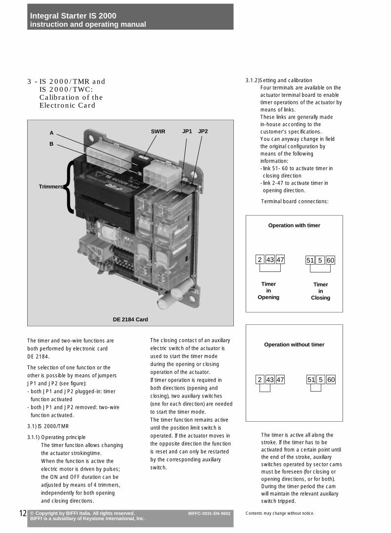
3.1.2)Setting and calibrationFour terminals are available on theactuator terminal board to enabletimer operations of the actuator bymeans of links.These links are generally madein-house according to thecustomer’s specifications.You can anyway change in fieldthe original configuration bymeans of the followinginformation:- link 51- 60 to activate timer inclosing direction
- link 2-47 to activate timer inopening direction.
Terminal board connections:
The timer is active all along thestroke. If the timer has to beactivated from a certain point untilthe end of the stroke, auxiliaryswitches operated by sector camsmust be foreseen (for closing oropening directions, or for both).During the timer period the camwill maintain the relevant auxiliaryswitch tripped.
The closing contact of an auxiliaryelectric switch of the actuator isused to start the timer modeduring the opening or closingoperation of the actuator.If timer operation is required inboth directions (opening andclosing), two auxiliary switches(one for each direction) are neededto start the timer mode.The timer function remains activeuntil the position limit switch isoperated. If the actuator moves inthe opposite direction the functionis reset and can only be restartedby the corresponding auxiliaryswitch.
3 - IS 2000/TMR andIS 2000/TWC:Calibration of theElectronic Card
The timer and two-wire functions areboth performed by electronic cardDE 2184.
The selection of one function or theother is possible by means of jumpersJP1 and JP2 (see figure):- both JP1 and JP2 plugged-in: timer
function activated- both JP1 and JP2 removed: two-wire
function activated.
3.1) IS 2000/TMR
3.1.1) Operating principle The timer function allows changingthe actuator strokingtime.When the function is active theelectric motor is driven by pulses;the ON and OFF duration can beadjusted by means of 4 trimmers,independently for both openingand closing directions.
2 4743 51 605
12 © Copyright by BIFFI Italia. All rights reserved.BIFFI is a subsidiary of Keystone International, Inc.
Integral Starter IS 2000instruction and operating manual
BIFFC-0031-EN-9602 Contents may change without notice.
Operation with timer
Timerin
Opening
Timerin
Closing
2 4743 51 605
Operation without timer
Trimmers{
DE 2184 Card
SWIRA
B
JP1 JP2
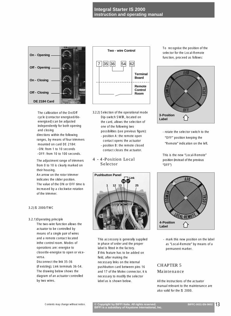
To recognise the position of theselector for the Local-Remotefunction, proceed as follows:
- rotate the selector switch to the
“OFF” position keeping the
“Remote” indication on the left.
This is the new “Local-Remote”
position (instead of the previous
“OFF”)
- mark this new position on the labelas “Local-Remote” by means of apermanent marker.
CHAPTER 5Maintenance
All the instructions of the actuatormanual relevant to the maintenance arealso valid for the IS 2000.
3.2.2) Selection of the operational modeDip-switch SWIR, located onthe card, allows the selection ofone of the following twopossibilities (see previous figure):- position A: the remote open
contact opens the actuator- position B: the remote closed
contact closes the actuator.
4 - 4-Position LocalSelector
This accessory is generally suppliedin phase of order and the properlabel is fitted in the factory.If this feature has to be added onfield, after making thenecessary links on the internalpushbutton card between pins 16and 17 of the Molex connector, it isnecessary to modify the selectorlabel as is shown below.
13© Copyright by BIFFI Italia. All rights reserved.BIFFI is a subsidiary of Keystone International, Inc.
Integral Starter IS 2000instruction and operating manual
BIFFC-0031-EN-9602Contents may change without notice.
The calibration of the On/Offcycle (contactor energised/de-energised) can be adjustedindependently for both openingand closing
directions within the followingranges, by means of four trimmersmounted on card DE 2184:-ON: from 1 to 10 seconds-OFF: from 10 to 100 seconds.
The adjustment range of trimmersfrom 0 to 10 is clearly marked ontheir housing.An arrow on the rotor trimmerindicates the slider position.The value of the ON or OFF time isincreased by a clockwise rotationof the trimmer.
3.2) IS 2000/TWC
3.2.1)Operating principleThe two-wire function allows theactuator to be controlled bymeans of a single pair of wiresand a remote contact locatedinthe control room. Modes ofoperations are: energise toclose/de-energise to open or vice-versa.Disconnect the link 35-36(if existing). Link terminals 36-54.The drawing below shows thediagram of an actuator controlledby two wires.
DE 2184 Card
On - Opening
Off - Opening
On - Closing
Off - Closing
Pushbutton Panel
1 12 13 25
Link
3-PositionLabel
4-PositionLabel
7 36 54 6235
Two - wire Control
TerminalBoard
RemoteControlRoom
16 17
14 © Copyright by BIFFI Italia. All rights reserved.BIFFI is a subsidiary of Keystone International, Inc.
Integral Starter IS 2000instruction and operating manual
BIFFC-0031-EN-9602 Contents may change without notice.
CHAPTER 6Trouble-Shooting
INDEX
1) The actuator does not work electrically
2) The actuator does not start on remotecontrol
3) The actuator does not start on localcontrol
4) The actuator does not workstep-by-step (for IS 2000/TMR)
The IS 2000 has already passed thefunctional test performed by Biffi QualityAssurance personnel, therefore it shouldonly be opened if the electrical tests atthe terminal board indicate an internalmalfunction.
Only for “C” Series actuators: if duringtrouble-shooting the valve must not beactuated, be sure that the engagementlever is locked in the “handwheeloperation” position.
1 -The Actuator Does notWork Electrically
1.1) Check the possible causes andremedies already described in theproper actuator instruction manual
1.2) Check the phase discriminatordip-switch
1.3) If the red LED is flashing, there is anincorrect connection of the phases(this occurs only in 3Ph systems andwhen the alarm mode is selected):reverse two phases of the supplyline and try again.
1.4) If all LED’s are off, check allthecontrol fuses: replace them ifnecessary.Always check the cause of thismalfunction.
2 -The Actuator Does notStart on RemoteControl
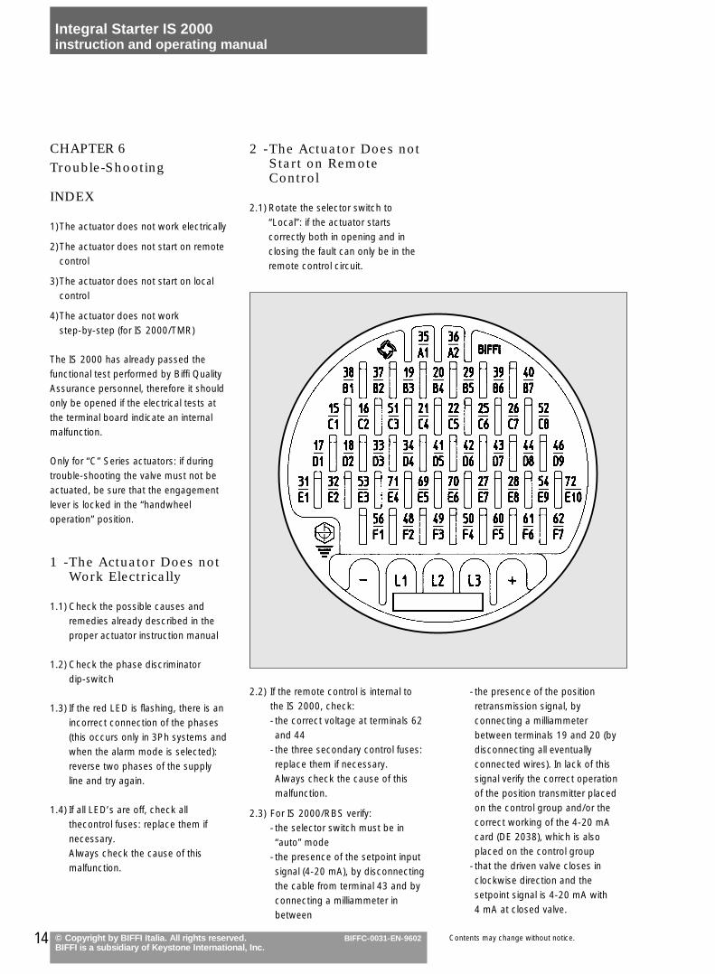
2.1) Rotate the selector switch to“Local”: if the actuator startscorrectly both in opening and inclosing the fault can only be in theremote control circuit.
2.2) If the remote control is internal tothe IS 2000, check:- the correct voltage at terminals 62and 44
-the three secondary control fuses:replace them if necessary.Always check the cause of thismalfunction.
2.3) For IS 2000/RBS verify:- the selector switch must be in“auto” mode
-the presence of the setpoint inputsignal (4-20 mA), by disconnectingthe cable from terminal 43 and byconnecting a milliammeter inbetween
-the presence of the positionretransmission signal, byconnecting a milliammeterbetween terminals 19 and 20 (bydisconnecting all eventuallyconnected wires). In lack of thissignal verify the correct operationof the position transmitter placedon the control group and/or thecorrect working of the 4-20 mAcard (DE 2038), which is alsoplaced on the control group
-that the driven valve closes inclockwise direction and thesetpoint signal is 4-20 mA with4 mA at closed valve.
15© Copyright by BIFFI Italia. All rights reserved.BIFFI is a subsidiary of Keystone International, Inc.
Integral Starter IS 2000instruction and operating manual
BIFFC-0031-EN-9602Contents may change without notice.
2.4) For IS 2000/TMR or IS 2000/TWCverify:- the correct voltage at terminals 62and 44
-the three secondary control fuses.If the above is correct, there is afault in card DE 2184.
3 - The Actuator Does notStart on Local Control
3.1) If all LED’s are off, verify:- the presence of the control supply-the three secondary control fuses:
CHAPTER 7
Recommended SpareParts
INDEX
1) Commissioning spare parts kits
2) Recommended spare parts fortwo-years’ operation
replace them if necessary.Always check the cause of thismalfunction.
3.2) If one or both position LED’s areon, verify:- the surface temperature of themotor: if it is very hot wait until themotor cools down to enable theautomatic reset of the thermalswitch or of other thermal relayswhich may be present in the powersupply circuit
- the three secondary control fuses:replace them if necessary.Always check the cause of thismalfunction.
3.3) For IS 2000/RBS verify that theselector switch is in “manual” mode.
3.4) At completely open or closed valveposition the LED keeps on blinking.Check the valve position settingsvalues and re-set them adescribed in this manual.
4 - The Actuator Does notWork Step-by-Step(for IS 2000/TMR)
-Check the correct calibration of thefour trimmers according to thedesired operation, both in closingand in opening
-check the correct setting of bothcams of auxiliary limit switches.
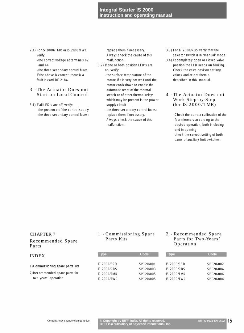
1 - Commissioning Spare Parts Kits
Type Code
IS 2000/ESD SPI 20/001IS 2000/RBS SPI 20/003IS 2000/TMR SPI 20/005IS 2000/TWC SPI 20/005
2 - Recommended Spare Parts for Two-Years’ Operation
Type Code
IS 2000/ESD SPI 20/002IS 2000/RBS SPI 20/004IS 2000/TMR SPI 20/006IS 2000/TWC SPI 20/006

© Copyright by BIFFI Italia. All rights reserved.BIFFI is a subsidiary of Keystone International, Inc.
BIFFC-0031-EN-9602
Local Sales Organizations:
BIFFI ITALIA s.r.l. - Loc. Caselle S. Pietro - 29017 Fiorenzuola d’Arda - Piacenza - ITALY - Tel. (0523) 944411 - Fax (0523) 941885 - Telex 530107 - 531447
A.C
./G
rafic
he M
alve
zzi/2
.000
/05.
96E
-IM
/IS-E
Rev
. 2