Embed Size (px)
Citation preview
BIG-IP® Application Security Manager™:Implementations
Version 11.2

Table of Contents
Legal Notices.....................................................................................................................................7
Acknowledgments............................................................................................................................9
Chapter 1: Setting Up IP Address Intelligence Blocking.................................13Overview: Setting up IP address intelligence blocking...........................................................14
Enabling IP address intelligence.................................................................................14
Setting up IP address intelligence blocking.................................................................15
Reviewing IP address intelligence statistics................................................................16
Creating an iRule to log IP address intelligence information.......................................16
Creating an iRule to reject requests with questionable IP addresses.........................17
IP address intelligence categories..........................................................................................18
Chapter 2: Managing IP Address Exceptions...................................................19Overview: Managing IP address exceptions...........................................................................20
Creating IP address exceptions...................................................................................20
Deleting IP address exceptions...................................................................................21
Updating IP address exceptions..................................................................................21
Chapter 3: Enforcing Application Use at Specific Geolocations....................23Overview: Enforcing application use in certain geolocations..................................................24
Enforcing application use in certain geolocations..................................................................24
Setting up geolocation enforcement from a request ..............................................................25
Chapter 4: Synchronizing Application Security Configurations.....................27Overview: Synchronizing application security configurations.................................................28
Considerations for application security synchronization.........................................................28
Overview: Synchronizing two ASM systems..........................................................................29
Performing basic network configuration for synchronization........................................29
Adding a device to the device trust..............................................................................30
Creating a Sync-Failover device group........................................................................30
Specifying IP addresses for failover.............................................................................31
Enabling ASM synchronization on a device group......................................................31
Manually synchronizing an ASM-enabled device group..............................................32
Result: Synchronizing two ASM systems....................................................................32
Overview: Synchronizing multiple ASM systems....................................................................33
Performing basic network configuration for synchronization........................................33
Adding a device to the device trust..............................................................................34
3
Table of Contents
Creating a Sync-Failover device group........................................................................34
Specifying IP addresses for failover.............................................................................35
Creating a Sync-Only device group.............................................................................35
Enabling ASM synchronization on a Sync-Only device group.....................................36
Manually synchronizing the BIG-IP configuration........................................................36
Result: Synchronizing multiple ASM systems..............................................................37
Overview: Synchronizing ASM systems for disaster recovery................................................37
Performing basic network configuration for synchronization........................................38
Adding a device to the device trust..............................................................................38
Creating a Sync-Failover device group........................................................................39
Specifying IP addresses for failover.............................................................................39
Creating a Sync-Only device group.............................................................................40
Enabling ASM synchronization on a Sync-Only device group.....................................40
Manually synchronizing the BIG-IP configuration........................................................41
Result: Synchronizing ASM systems for disaster recovery..........................................41
Chapter 5: Configuring Application Security Session Tracking......................43Overview: Tracking application security sessions using login pages......................................44
Creating login pages....................................................................................................44
Enforcing login pages..................................................................................................45
Setting up session tracking..........................................................................................46
Monitoring user and session information.....................................................................47
Chapter 6: Tracking Application Security Sessions with APM........................49Overview: Tracking application security sessions using APM................................................50
Prerequisites for setting up session tracking with APM..........................................................50
Creating a VLAN..........................................................................................................50
Creating a self IP address for a VLAN.........................................................................51
Creating a local traffic pool for application security ....................................................51
Creating an HTTP class..............................................................................................52
Creating a virtual server to manage HTTPS traffic......................................................52
Creating a security policy automatically......................................................................53
Creating an access profile...........................................................................................55
Configuring an access policy.......................................................................................57
Adding the access profile to the virtual server.............................................................57
Setting up ASM session tracking with APM.................................................................58
Monitoring user and session information.....................................................................59
Chapter 7:
Automatically Creating Security Policies for AJAX Applications...............61Application security for applications that use AJAX................................................................62
4
Table of Contents
Overview: Creating a security policy for applications that use AJAX......................................62
Creating a security policy automatically......................................................................62
Reviewing security policy status..................................................................................64
Implementation result.............................................................................................................65
Chapter 8: Adding JSON Support to an Existing Security Policy...................67Overview: Adding JSON support to existing security policies................................................68
Creating a JSON profile...............................................................................................68
Associating a JSON profile with a URL.......................................................................69
Associating a JSON profile with a parameter..............................................................70
Implementation result.............................................................................................................70
Chapter 9:
Adding AJAX Blocking Response Behavior to a Security Policy...............71Overview: Adding AJAX blocking and login response behavior.............................................72
Configuring the blocking response for AJAX applications......................................................72
5
Table of Contents

6
Table of Contents
Legal Notices
Publication Date
This document was published on May 7, 2012.
Publication Number
MAN-0358-02
Copyright
Copyright © 2012, F5 Networks, Inc. All rights reserved.
F5 Networks, Inc. (F5) believes the information it furnishes to be accurate and reliable. However, F5 assumesno responsibility for the use of this information, nor any infringement of patents or other rights of thirdparties which may result from its use. No license is granted by implication or otherwise under any patent,copyright, or other intellectual property right of F5 except as specifically described by applicable userlicenses. F5 reserves the right to change specifications at any time without notice.
Trademarks
3DNS, Access Policy Manager, Acopia, Acopia Networks, Advanced Client Authentication, AdvancedRouting, APM, Application Security Manager, ARX, AskF5, ASM, BIG-IP, Cloud Extender, CloudFucious,CMP, Data Manager, DevCentral, DevCentral [DESIGN], DNS Express, DSC, DSI, Edge Client, EdgeGateway, Edge Portal, EM, Enterprise Manager, F5, F5 [DESIGN], F5 Management Pack, F5 Networks,F5 World, Fast Application Proxy, Fast Cache, FirePass, Global Traffic Manager, GTM, IBR, IntelligentBrowser Referencing, Intelligent Compression, IPv6 Gateway, iApps, iControl, iHealth, iQuery, iRules,iRules OnDemand, iSession, IT agility. Your way., L7 Rate Shaping, LC, Link Controller, Local TrafficManager, LTM, Message Security Module, MSM, Netcelera, OneConnect, Packet Velocity, ProtocolSecurity Module, PSM, Real Traffic Policy Builder, ScaleN, SSL Acceleration, StrongBox, SuperVIP, SYNCheck, TCP Express, TDR, TMOS, Traffic Management Operating System, TrafficShield, TransparentData Reduction, VIPRION, vCMP, WA, WAN Optimization Manager, WANJet, WebAccelerator, WOM,and ZoneRunner, are trademarks or service marks of F5 Networks, Inc., in the U.S. and other countries,and may not be used without F5's express written consent.
All other product and company names herein may be trademarks of their respective owners.
Patents
This product may be protected by U.S. Patent 6,311,278. This list is believed to be current as of May 7,2012.
Export Regulation Notice
This product may include cryptographic software. Under the Export Administration Act, the United Statesgovernment may consider it a criminal offense to export this product from the United States.
RF Interference Warning
This is a Class A product. In a domestic environment this product may cause radio interference, in whichcase the user may be required to take adequate measures.
FCC Compliance
This equipment has been tested and found to comply with the limits for a Class A digital device pursuantto Part 15 of FCC rules. These limits are designed to provide reasonable protection against harmfulinterference when the equipment is operated in a commercial environment. This unit generates, uses, andcan radiate radio frequency energy and, if not installed and used in accordance with the instruction manual,may cause harmful interference to radio communications. Operation of this equipment in a residential areais likely to cause harmful interference, in which case the user, at his own expense, will be required to takewhatever measures may be required to correct the interference.
Any modifications to this device, unless expressly approved by the manufacturer, can void the user's authorityto operate this equipment under part 15 of the FCC rules.
Canadian Regulatory Compliance
This Class A digital apparatus complies with Canadian ICES-003.
Standards Compliance
This product conforms to the IEC, European Union, ANSI/UL and Canadian CSA standards applicable toInformation Technology products at the time of manufacture.
8
Legal Notices
Acknowledgments
This product includes software developed by Bill Paul.
This product includes software developed by Jonathan Stone.
This product includes software developed by Manuel Bouyer.
This product includes software developed by Paul Richards.
This product includes software developed by the NetBSD Foundation, Inc. and its contributors.
This product includes software developed by the Politecnico di Torino, and its contributors.
This product includes software developed by the Swedish Institute of Computer Science and its contributors.
This product includes software developed by the University of California, Berkeley and its contributors.
This product includes software developed by the Computer Systems Engineering Group at the LawrenceBerkeley Laboratory.
This product includes software developed by Christopher G. Demetriou for the NetBSD Project.
This product includes software developed by Adam Glass.
This product includes software developed by Christian E. Hopps.
This product includes software developed by Dean Huxley.
This product includes software developed by John Kohl.
This product includes software developed by Paul Kranenburg.
This product includes software developed by Terrence R. Lambert.
This product includes software developed by Philip A. Nelson.
This product includes software developed by Herb Peyerl.
This product includes software developed by Jochen Pohl for the NetBSD Project.
This product includes software developed by Chris Provenzano.
This product includes software developed by Theo de Raadt.
This product includes software developed by David Muir Sharnoff.
This product includes software developed by SigmaSoft, Th. Lockert.
This product includes software developed for the NetBSD Project by Jason R. Thorpe.
This product includes software developed by Jason R. Thorpe for And Communications, http://www.and.com.
This product includes software developed for the NetBSD Project by Frank Van der Linden.
This product includes software developed for the NetBSD Project by John M. Vinopal.
This product includes software developed by Christos Zoulas.
This product includes software developed by the University of Vermont and State Agricultural College andGarrett A. Wollman.
This product includes software developed by Balazs Scheidler ([email protected]), which is protected underthe GNU Public License.
This product includes software developed by Niels Mueller ([email protected]), which is protected underthe GNU Public License.
In the following statement, This software refers to the Mitsumi CD-ROM driver: This software was developedby Holger Veit and Brian Moore for use with 386BSD and similar operating systems. Similar operatingsystems includes mainly non-profit oriented systems for research and education, including but not restrictedto NetBSD, FreeBSD, Mach (by CMU).
This product includes software developed by the Apache Group for use in the Apache HTTP server project(http://www.apache.org/).
This product includes software licensed from Richard H. Porter under the GNU Library General PublicLicense (© 1998, Red Hat Software), www.gnu.org/copyleft/lgpl.html.
This product includes the standard version of Perl software licensed under the Perl Artistic License (© 1997,1998 Tom Christiansen and Nathan Torkington). All rights reserved. You may find the most current standardversion of Perl at http://www.perl.com.
This product includes software developed by Jared Minch.
This product includes software developed by the OpenSSL Project for use in the OpenSSL Toolkit(http://www.openssl.org/).
This product includes cryptographic software written by Eric Young ([email protected]).
This product contains software based on oprofile, which is protected under the GNU Public License.
This product includes RRDtool software developed by Tobi Oetiker (http://www.rrdtool.com/index.html)and licensed under the GNU General Public License.
This product contains software licensed from Dr. Brian Gladman under the GNU General Public License(GPL).
This product includes software developed by the Apache Software Foundation (http://www.apache.org/).
This product includes Hypersonic SQL.
This product contains software developed by the Regents of the University of California, Sun Microsystems,Inc., Scriptics Corporation, and others.
This product includes software developed by the Internet Software Consortium.
This product includes software developed by Nominum, Inc. (http://www.nominum.com).
This product contains software developed by Broadcom Corporation, which is protected under the GNUPublic License.
This product contains software developed by MaxMind LLC, and is protected under the GNU Lesser GeneralPublic License, as published by the Free Software Foundation.
This product includes the Zend Engine, freely available at http://www.zend.com.
This product contains software developed by NuSphere Corporation, which is protected under the GNULesser General Public License.
This product contains software developed by Erik Arvidsson and Emil A Eklund.
This product contains software developed by Aditus Consulting.
This product contains software developed by Dynarch.com, which is protected under the GNU LesserGeneral Public License, version 2.1 or above.
This product contains software developed by InfoSoft Global (P) Limited.
This product includes software written by Steffen Beyer and licensed under the Perl Artistic License andthe GPL.
10
Acknowledgments
This product includes software written by Makamaka Hannyaharamitu ©2007-2008.
11
BIG-IP® Application Security Manager™: Implementations

12
Acknowledgments
Chapter
1
Setting Up IP Address Intelligence Blocking
Topics:
• Overview: Setting up IP address intelligenceblocking
• IP address intelligence categories
Overview: Setting up IP address intelligence blocking
In Application Security Manager™, you can use IP address intelligence blocking in a security policy to blockrequests from IP addresses that have questionable reputations. IP addresses from which attacks or spamhave originated are included in an IP intelligence database, along with the category describing the problem.The BIG-IP® system must connect to the IP intelligence database before you can use IP address intelligenceblocking.
You can configure a security policy to log (alarm) or block requests from IP addresses of questionablereputation, and to perform different actions depending on the categories of problems. For example, you canblock requests from IP addresses associated with Windows exploits and log requests from scanners.
You can create a whitelist of IP addresses that might be in the database, and allow them to access the webapplication regardless of their IP reputation. This is a way to ensure that traffic from known sources is notblocked because of IP address intelligence data.
You can also use iRules® to instruct the system how to use IP address intelligence information.
Task Summary
These are tasks for setting up IP address intelligence blocking in a security policy.
Enabling IP address intelligence
Setting up IP address intelligence blocking
Reviewing IP address intelligence statistics
Creating an iRule to log IP address intelligence information
Creating an iRule to reject requests with questionable IP addresses
Enabling IP address intelligence
The requirements for using IP address intelligence are:
• The system must have an IP Intelligence license.• The system must have an Internet connection either directly or through a proxy server.• The system must have DNS configured (go to System > Configuration > Device > DNS).
Important: IP address intelligence is enabled by default. You only need to enable it if it waspreviously disabled.
To enable IP address intelligence on the BIG-IP® system, you enable auto-update to connect the system tothe IP intelligence database.
1. Log in to the command line for the BIG-IP® system.
2. To determine whether IP intelligence is enabled, type the following command: tmsh list sys dbiprep.autoupdate
If the value of the iprep.autoupdate variable is disable, IP intelligence is not enabled. If it isenable, your task is complete.
3. At the prompt, type tmsh modify sys db iprep.autoupdate value enable
The system downloads the IP intelligence database and stores it in the binary file,/var/IpRep/F5IpRep.dat. It is updated every 5 minutes.
14
Setting Up IP Address Intelligence Blocking
4. If the BIG-IP system is behind a firewall, make sure that the BIG-IP system has external access tovector.brightcloud.com using port 443. That is the IP Intelligence server from which the systemgets IP Intelligence information.
5. (Optional) If the BIG-IP system connects to the Internet using a forward proxy server, set these systemdatabase variables.
a) Type tmsh modify sys db proxy.host value hostname to specify the hostname of theproxy server.
b) Type tmsh modify sys db proxy.port value port_number to specify the port number ofthe proxy server.
c) Type tmsh modify sys db proxy.username value hostname to specify the user name tolog in to the proxy server.
d) Type tmsh modify sys db proxy.password value password to specify the password tolog in to the proxy server.
The IP address intelligence feature remains enabled unless you disable it with the command tmsh modifysys db iprep.autoupdate value disable.
You can create iRules® to instruct the system how to handle traffic from IP addresses with questionablereputations, or use Application Security Manager™ to configure IP address intelligence blocking.
Setting up IP address intelligence blocking
Before you can set up IP address intelligence blocking, your system must have IP address intelligenceenabled.
You can configure a security policy to log and block requests from source IP addresses that, according toan IP intelligence database, have a bad reputation and could cause a potential attack.
1. On the Main tab, click Application Security > IP Addresses > IP Address Intelligence.The IP Address Intelligence screen opens.
2. In the Current edited policy list near the top of the screen, verify that the edited security policy is theone you want to work on.
3. For the IP Address Intelligence setting, select the Enabled check box.
4. For the IP Address Whitelist setting, specify any IP addresses you want to allow, even if they are foundin the IP intelligence database.
a) Type the IP Address and Subnet Mask of the address to consider safe.b) Click Add.
The addresses that you typed are added to the list.
5. In the IP Address Intelligence Categories area, select Alarm or Block, or both, for the categories of IPaddresses you are interested in.
• Select Alarm to cause the system to log the IP address intelligence data (IP address intelligencecategory and status) on the Requests screen whenever a request is from a source IP address in thatcategory.
• Select Block to stop requests sent from a source IP address that matches that category
Note: If these settings are not available, click Policy > Blocking and for the violation Accessfrom malicious IP address, select the Alarm and Block settings.
6. Click Save.
15
BIG-IP® Application Security Manager™: Implementations
The system matches source IP addresses to those in the IP address intelligence database. When a match isfound, the violation Access from malicious IP address occurs. The system determines what categoryof reputation the IP address has, then logs or blocks the IP address according to how the IP AddressIntelligence categories are set.
Reviewing IP address intelligence statistics
Before you can view IP address intelligence statistics, your system must have IP address intelligence enabled.
After you set up IP intelligence blocking on the Application Security Manager™, you can review statisticsconcerning how many requests were received from IP addresses with questionable reputations. You canalso view the requests from those IP addresses.
1. On the Main tab, click Application Security > Reporting > Charts.The Charts screen opens, where you can view graphical reports.
2. In the Charts area, next to View by, click IP Address Intelligence.The chart shows details about IP addresses that were used to send the illegal requests, grouped accordingto their reputation in the IP intelligence database.
3. Hover over the pie chart or look at the Details table below it to see the categories of IP addresses withquestionable reputations.
4. Under Chart Path on the left, click View Requests to see the requests from IP addresses in the IPintelligence database.The Requests list opens.
5. Click any request to view details about the request.The screen expands to show more information about the request. IP address intelligence information isshown in the Source IP Address field in the request details. The details include the category of themalicious IP address and information about when the IP intelligence database was last updated.
6. If you have set up remote logging, you can also review IP intelligence data on the remote logger.
By reviewing the IP address intelligence data, you can examine requests from potentially malicious IPaddresses.
Based on the statistics and IP address intelligence categories that the IP addresses fall into, you can adjustwhat happens (alarm or block) when the system receives requests from IP addresses in different categories.
Creating an iRule to log IP address intelligence information
Before you can create an iRule to log IP address intelligence information, your system must have IP addressintelligence enabled.
You use iRules® to log IP address intelligence categories to the file /var/log/ltm. This is an example ofthe type of iRule you can write.
1. On the Main tab, click Local Traffic > iRules.The iRule List screen opens, displaying any existing iRules.
2. Click Create.The New iRule screen opens.
3. In the Name field, type a name between 1 and 31 characters, such as my_iRule.
4. In the Definition field, type the iRule using Tool Command Language (Tcl) syntax.
16
Setting Up IP Address Intelligence Blocking
For example, to log all IP addresses and any associated IP address intelligence categories, type thefollowing iRule:
when CLIENT_ACCEPTED { log local0. "IP Address Intelligence for IP address [IP::client_addr]: [IP::reputation [IP::client_addr]]" }
5. Click Finished.The new iRule appears in the list.
When traffic is received from an IP address with a questionable reputation and that is included in the IPintelligence database, the system prints the IP address intelligence information in the /var/log/ltm log.
For complete and detailed information about iRules syntax, see the F5 Networks DevCentral web site,http://devcentral.f5.com.
Creating an iRule to reject requests with questionable IP addresses
Before you can create an iRule to reject requests based on an IP address reputation, your system must haveIP address intelligence enabled.
You can use iRules® to reject requests from IP addresses that have questionable reputations and are listedin the IP intelligence database. This is an example of the type of iRule you can write.
1. On the Main tab, click Local Traffic > iRules.The iRule List screen opens, displaying any existing iRules.
2. Click Create.The New iRule screen opens.
3. In the Name field, type a name between 1 and 31 characters, such as my_iRule.
4. In the Definition field, type the iRule using Tool Command Language (Tcl) syntax.
For example, to reject requests from IP addresses listed in the IP intelligence database because theycould be Windows Exploits or Web Attacks, type the following iRule:
when HTTP_REQUEST { set ip_reputation_categories [IP::reputation [IP::client_addr]] set is_reject 0 if {($ip_reputation_categories contains "Windows Exploits")} { set is_reject 1 } if {($ip_reputation_categories contains "Web Attacks")} { set is_reject 1 } if {($is_reject)} { log local0. "Attempted access from malicious IP address [IP::client_addr] ($ip_reputation_categories), request was rejected" HTTP::respond 200 content "<HTML><HEAD><TITLE>Rejected Request</TITLE> </HEAD><BODY>The request was rejected. <BR> Attempted access from malicious IP address</BODY></HTML>" }}
5. Click Finished.The new iRule appears in the list.
17
BIG-IP® Application Security Manager™: Implementations
When traffic is received from an IP address with a questionable reputation that is included in the IPintelligence database, the system prints the IP address intelligence information in the /var/log/ltm log.
For complete and detailed information about iRules syntax, see the F5 Networks DevCentral web site,http://devcentral.f5.com.
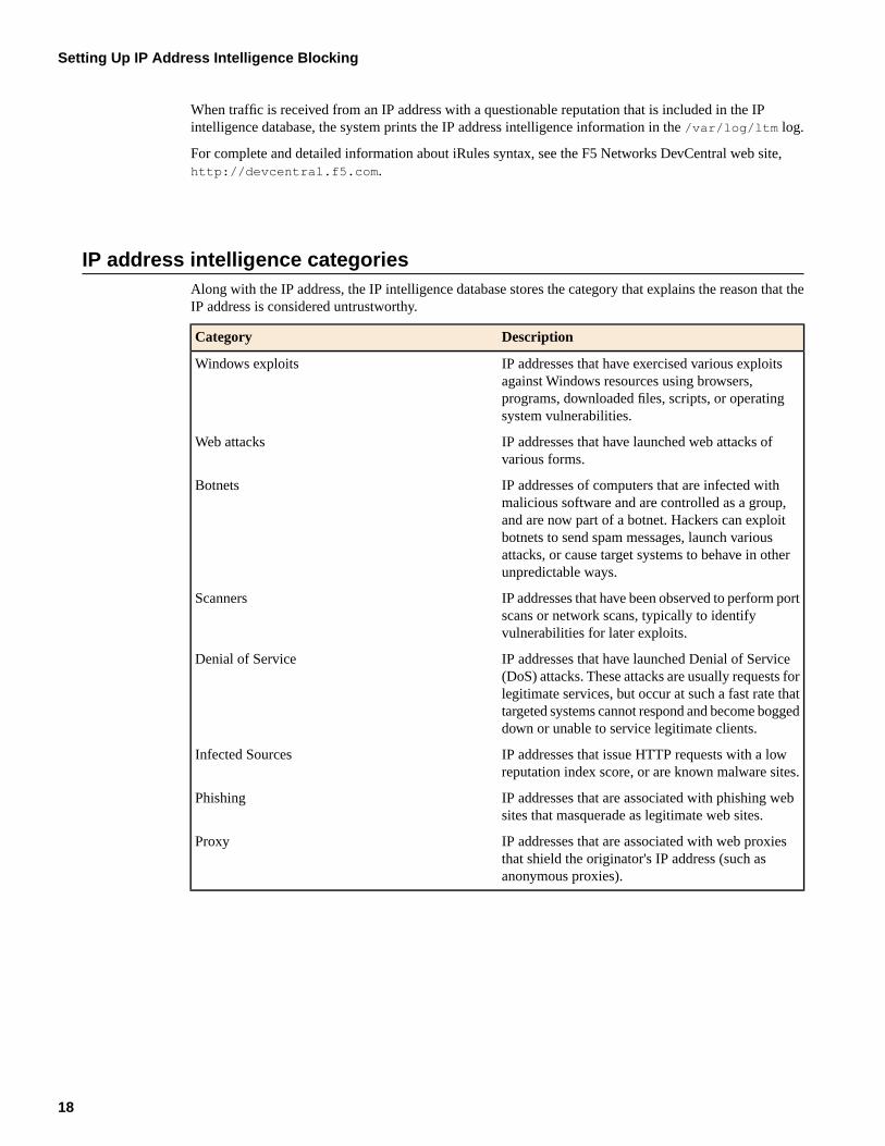
IP address intelligence categoriesAlong with the IP address, the IP intelligence database stores the category that explains the reason that theIP address is considered untrustworthy.
DescriptionCategory
IP addresses that have exercised various exploitsagainst Windows resources using browsers,
Windows exploits
programs, downloaded files, scripts, or operatingsystem vulnerabilities.
IP addresses that have launched web attacks ofvarious forms.
Web attacks
IP addresses of computers that are infected withmalicious software and are controlled as a group,
Botnets
and are now part of a botnet. Hackers can exploitbotnets to send spam messages, launch variousattacks, or cause target systems to behave in otherunpredictable ways.
IP addresses that have been observed to perform portscans or network scans, typically to identifyvulnerabilities for later exploits.
Scanners
IP addresses that have launched Denial of Service(DoS) attacks. These attacks are usually requests for
Denial of Service
legitimate services, but occur at such a fast rate thattargeted systems cannot respond and become boggeddown or unable to service legitimate clients.
IP addresses that issue HTTP requests with a lowreputation index score, or are known malware sites.
Infected Sources
IP addresses that are associated with phishing websites that masquerade as legitimate web sites.
Phishing
IP addresses that are associated with web proxiesthat shield the originator's IP address (such asanonymous proxies).
Proxy
18
Setting Up IP Address Intelligence Blocking
Chapter
2
Managing IP Address Exceptions
Topics:
• Overview: Managing IP address exceptions
Overview: Managing IP address exceptions
An IP address exception is an IP address that you want the system to treat in a specific way for a securitypolicy. For example, you can specify IP addresses from which the system should always trust traffic, IPaddresses for which you do not want the system to generate learning suggestions for the traffic, and IPaddresses for which you want to exclude information from the logs. You can use the IP address exceptionfeature to create exceptions for IP addresses of internal tools that your company uses, such as penetrationtools, manual or automatic scanners, or web scraping tools. You can add an IP address exception, andinstruct the system how to handle traffic coming from that address.
You can view a centralized list of IP address exceptions, and you can add new IP address exceptions to thelist. The list of IP address exceptions shows exceptions that you add directly to the list, or those which youadd from other locations, as shown by the following examples:
• When creating a security policy, you can specify IP addresses that you want the Policy Builder to alwaystrust.
• When creating a security policy that is integrated with a vulnerability assessment tool, you can configurethe scanner IP address as an IP address exception.
• When setting up anomaly detection (such as for DoS, brute force, and web scraping protections), youcan specify IP addresses that the system should consider legitimate (called whitelists).
• When setting up IP address intelligence, you can add IP addresses that the system should allow even ifthe IP address is in the IP intelligence database.
The IP Address Exceptions list shows in one location all of the IP exceptions configured for this securitypolicy. You can view or modify IP exceptions both from the centralized IP exception list and from thespecific feature screens.
This implementation describes how to create, delete, and update the list of IP address exceptions.
Creating IP address exceptions
For each security policy, you can create a list of IP address exceptions, and indicate how you want thesystem to handle the traffic from these IP addresses.
1. On the Main tab, click Application Security > IP Addresses > IP Address Exceptions.The IP Address Exceptions screen opens, and displays a centralized list of configured IP addressexceptions.
2. Click Create.The New IP Address Exception screen opens.
3. In the IP Address field, type the IP address that you want the system to trust.
Note: To add a route domain, type %n after the IP address where n is the route domainidentification number.
4. In the Netmask field, type the netmask of the IP address exception.
If you omit the netmask value, the system uses a default value of 255.255.255.255.
5. To consider traffic from this IP address as being safe, for the Policy Builder trusted IP setting, selectEnabled.The system adds this IP address to the Trusted IP Addresses setting on the Automatic Configurationscreen for the Policy Builder.
20
Managing IP Address Exceptions
6. To ignore this IP address when performing DoS, brute force, and web scraping detection, for the Ignorein Anomaly Detection setting, select Enabled.The system adds this IP address to the IP Address Whitelist setting on the anomaly detection screensfor DoS attacks, brute force, and web scraping.
7. If you do not want the system to generate learning suggestions for traffic sent from this IP address, forthe Ignore in Learning Suggestions setting, select Enabled.
Note: Application Security Manager does not generate learning suggestions for requests thatresult in the web server returning HTTP responses with 400 or 404 status codes unless thesecurity policy is configured to learn and block traffic (here both the Ignore in LearningSuggestions check box and the Never block this IP Address check box need to be disabled).
8. To never block traffic from this IP address, for the Never block this IP Address setting, select Enabled.
If the check box is cleared, a system in blocking mode blocks requests sent from this IP address accordingto the violation settings on the Policy Blocking Settings screen.
9. To prevent the system from logging requests (either legal or illegal) from this IP address, for the Neverlog requests from this IP setting, select Enabled.
10. To consider traffic from this IP address to be legitimate even if it is found in the IP Intelligence database,for the Ignore IP Intelligence setting, select Enabled.The system adds this IP address to the IP Address Whitelist setting on the IP Address Intelligencescreen.
11. Click Create.The IP Address Exceptions screen opens and shows all of the exceptions configured for the securitypolicy including the one you created.
You can view and manage all of your IP address exceptions from the centralized IP Address Exceptionsscreen.
Deleting IP address exceptions
If you no longer want an IP address on the exceptions list, you can delete the IP address exceptions.
1. On the Main tab, click Application Security > IP Addresses > IP Address Exceptions.The IP Address Exceptions screen opens, and displays a centralized list of configured IP addressexceptions.
2. Select the IP address exception you want to delete and click Delete.The IP address exception is deleted from the list.
3. You can also delete IP address exceptions from the anomaly detection whitelists, the IP addressintelligence whitelist, and the policy building configuration. On any of these screens, select the IPaddress, and click Delete.The system removes the IP address from the whitelist on the screen. However, the IP address remainson the IP Address Exceptions screen with the related setting changed. For example, if you deleted theIP address from an anomaly detection whitelist, the Anomaly Detection column for that IP address inthe exceptions list changes from Ignore IP to say Include IP.
4. In the editing context area, click Apply Policy to immediately put the changes into effect.
Updating IP address exceptions
You can update IP address exceptions from the centralized list of IP address exceptions.
21
BIG-IP® Application Security Manager™: Implementations
1. On the Main tab, click Application Security > IP Addresses > IP Address Exceptions.The IP Address Exceptions screen opens, and displays a centralized list of configured IP addressexceptions.
2. Click the IP address of the IP address exception you want to modify.The IP Address Exception Properties screen opens.
3. Change the settings as needed.
4. Click Update.
5. In the editing context area, click Apply Policy to immediately put the changes into effect.
22
Managing IP Address Exceptions
Chapter
3
Enforcing Application Use at Specific Geolocations
Topics:
• Overview: Enforcing application use incertain geolocations
• Enforcing application use in certaingeolocations
• Setting up geolocation enforcement from arequest
Overview: Enforcing application use in certain geolocations
Geolocation software can identify the geographic location of a client or web application user. Geolocationrefers either to the process of assessing the location, or to the actual assessed location.
For applications protected by Application Security Manager™, you can use geolocation enforcement torestrict or allow application use in specific countries. You adjust the lists of which countries or locationsare allowed or disallowed in a security policy. If an application user tries to access the web application froma location that is not allowed, the Access from disallowed GeoLocation violation occurs. By default,all locations are allowed, and the violation learn, alarm, and block flags are enabled.
Requests from certain locations, such as RFC-1918 addresses or unassigned global addresses, do not includea valid country code. The geolocation is shown as N/A in both the request, and the list of geolocations. Youhave the option to disallow N/A requests whose country of origination is unknown.
Enforcing application use in certain geolocations
Before you can set up geolocation enforcement, you need to create a security policy. If the BIG-IP®systemis deployed behind a proxy, you might need to set the Trust XFF Header option in the security policyproperties. Then the system identifies the location using the address from the XFF header instead of thesource IP address.
You can set up a security policy to allow or disallow access to the web application by users in specificcountries, areas, or from anonymous proxies.
1. On the Main tab, click Application Security > Policy > Geolocation Enforcement.
2. In the Current edited policy list near the top of the screen, verify that the edited security policy is theone you want to work on.
3. In the Geolocation List setting, use the move buttons to adjust the lists of allowed and disallowedgeolocations. To restrict traffic from anonymous proxies, move Anonymous Proxy to the disallowedgeolocations list.
If no geolocations are assigned, the list displays the word None. The screen shows the value N/A in thelist of geolocations for cases where a user is in a location that cannot be identified, for example, if usingRFC-1918 addresses or unassigned global addresses.
Tip: You can approach geolocation enforcement by specifying either which locations you wantto disallow or which locations you want to allow.
4. Click Save.
5. In the editing context area, click Apply Policy to immediately put the changes into effect.
Now, if a user in a disallowed location attempts to access the web application, the security policy (if inblocking mode) blocks the user and displays the violation Access from disallowed Geolocation.
24
Enforcing Application Use at Specific Geolocations
Setting up geolocation enforcement from a request
You can restrict application use in certain geolocations by using the Requests list. This is an easy way torestrict users in a certain country from accessing the web application. By examining illegal request details,you can disallow the locations from which frequent problems are originating.
1. On the Main tab, expand Application Security and click Reporting.The Requests screen opens and shows all illegal requests that have occurred for this security policy.
2. In the Request List, click anywhere on a request.The screen displays details about the request including any violations associated with the request, andother details, such as the geolocation.
3. In the Request Details area, next to Geolocation, the country is displayed, and if the country is not onthe disallowed geolocation list, you see Disallow this Geolocation.The system asks you to verify that you want to disallow this geolocation. When you verify that you do,the system adds the country to the geolocation disallowed list.
4. Apply the change to the security policy: on the Main tab, click Policy, and then click Apply Policy.
5. On the menu bar, click Geolocation Enforcement.The Geolocation Enforcement screen opens, and you can see that the country was added to the disallowedgeolocations list.
Now, if a user in a disallowed location attempts to access the web application, the security policy (if inblocking mode) blocks the user and displays the violation Access from disallowed Geolocation.
25
BIG-IP® Application Security Manager™: Implementations

26
Enforcing Application Use at Specific Geolocations
Chapter
4
Synchronizing Application Security Configurations
Topics:
• Overview: Synchronizing application securityconfigurations
• Considerations for application securitysynchronization
• Overview: Synchronizing two ASM systems• Overview: Synchronizing multiple ASM
systems• Overview: Synchronizing ASM systems for
disaster recovery
Overview: Synchronizing application security configurations
You can use device management to set up several BIG-IP® systems running Application Security Manager™
(ASM) so that they synchronize their security policies and configurations. By using application securitysynchronization, you can set up application security and create security policies on one system and canpropagate them to other systems in an application security device group. In BIG-IP ASM™, a device groupis two or more BIG-IP devices using the same configuration and providing consistent security policyenforcement.
You can set up application security synchronization, for example, behind an Application Delivery Controllerwhere multiple BIG-IP systems running Application Security Manager are deployed as members of a pool.The options and security policies on all of the systems stay in sync regardless of where you update them.
This implementation comprises two phases:
• Establishing a trust relationship, known as a device trust, between the BIG-IP ASM devices that youwant to share security policies and configurations. The device trust initiates a line of communicationbetween the ASM devices (in a trusted way by using digital certificates).
• Adding the ASM devices that are members of the device trust to a device group, then enabling ASMsynchronization on the device group. The ASM-enabled device group is the collection of BIG-IP devicesthat trust each other and can synchronize their ASM configurations and security policies.
When you set up ASM™ synchronization, in addition to security policies, other settings, such as customattack signatures, logging profiles, SMTP configuration, anti-virus protection, system variables, and policytemplates, are synchronized with all devices in the ASM-enabled device group.
Considerations for application security synchronization
When using device management with Application Security Manager™ (ASM™), you need to be aware ofthe following considerations that apply specifically to application security synchronization.
• A BIG-IP® system with Application Security Manager can be a member of only one ASM-enableddevice group.
• All BIG-IP systems in a device group must be running the same version (including hot fix updates) ofApplication Security Manager (version 11.0 or later).
• The BIG-IP systems in the ASM-enabled device group synchronize application security configurationdata and security policies, providing consistent enforcement on all the devices.
• Real Traffic Policy Builder® can run on only one system per security policy. For example, you can setup automatic security policy building on one system that is a member of an ASM-enabled device group,the policy is built on that system and then automatically updated on all of the systems in the devicegroup.
• If using a VIPRION® platform (with multiple blades), it is considered one device, and you need to addonly the master blade to the device trust and group.
28
Synchronizing Application Security Configurations
Overview: Synchronizing two ASM systems
This implementation describes how to set up two BIG-IP® systems running Application Security Manager™
(ASM) so that you can synchronize their security policies and configurations.
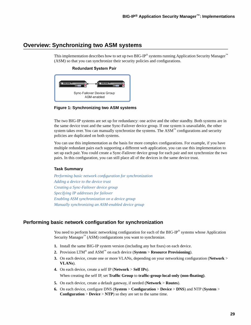
Figure 1: Synchronizing two ASM systems
The two BIG-IP systems are set up for redundancy: one active and the other standby. Both systems are inthe same device trust and the same Sync-Failover device group. If one system is unavailable, the othersystem takes over. You can manually synchronize the systems. The ASM™ configurations and securitypolicies are duplicated on both systems.
You can use this implementation as the basis for more complex configurations. For example, if you havemultiple redundant pairs each supporting a different web application, you can use this implementation toset up each pair. You could create a Sync-Failover device group for each pair and not synchronize the twopairs. In this configuration, you can still place all of the devices in the same device trust.
Task Summary
Performing basic network configuration for synchronization
Adding a device to the device trust
Creating a Sync-Failover device group
Specifying IP addresses for failover
Enabling ASM synchronization on a device group
Manually synchronizing an ASM-enabled device group
Performing basic network configuration for synchronization
You need to perform basic networking configuration for each of the BIG-IP® systems whose ApplicationSecurity Manager™ (ASM) configurations you want to synchronize.
1. Install the same BIG-IP system version (including any hot fixes) on each device.
2. Provision LTM® and ASM™ on each device (System > Resource Provisioning).
3. On each device, create one or more VLANs, depending on your networking configuration (Network >VLANs).
4. On each device, create a self IP (Network > Self IPs).
When creating the self IP, set Traffic Group to traffic-group-local-only (non-floating).
5. On each device, create a default gateway, if needed (Network > Routes).
6. On each device, configure DNS (System > Configuration > Device > DNS) and NTP (System >Configuration > Device > NTP) so they are set to the same time.
29
BIG-IP® Application Security Manager™: Implementations
7. Verify connectivity between the devices (self IP address to self IP address). For example, use thiscommand to ensure communications: ping -I vlan_interface device_self_IP
8. On each device, specify the IP address to use when synchronizing configuration objects to the localdevice:
a) Click Device Management > Devices.b) Click the name of the local device.c) From the Device Connectivity menu, choose ConfigSync.d) For the Local Address setting, select the self IP address.e) Click Save Changes.
9. If your company requires special device certificates, install them on each device (System > DeviceCertificates and click Import).
The basic networking setup is complete for the BIG-IP ASM systems for which you want to share securitypolicies and configurations.
Adding a device to the device trust
Establish lines of communication between the BIG-IP® systems for which you want to synchronize securitypolicies and configurations by adding those systems to a device trust. You do this task on only one of thesystems.
1. On the Main tab, click Device Management > Device Trust > Local Domain.
2. In the Peer Authority Devices area of the screen, click Add.
3. Type an IP address, administrator user name, and administrator password for the remote BIG-IP® device.
This IP address can be either a management IP address or a self IP address.
4. Click Next.
5. Verify that the certificate of the remote device is correct.
6. Click Next.
7. Verify that the name of the remote device is correct.
8. Click Next.
9. Verify that the management IP address and name of the remote device are correct.
10. Click Next.
11. Confirm the new device trust: recheck the IP address and name, then click Finished.The system creates the trust domain and adds the devices to the Peer Authority Devices list. The truststatus of the devices is In Sync.
The BIG-IP ASM™ systems that you want to share security policies and configurations are now part of adevice trust.
Creating a Sync-Failover device group
This task establishes failover capability between two or more BIG-IP devices. If the active device in aSync-Failover device group becomes unavailable, the configuration objects fail over to another member ofthe device group and traffic processing is unaffected. You can perform this task on any authority devicewithin the local trust domain.
1. On the Main tab, click Device Management > Device Groups.The Device Groups screen displays a list of existing device groups.
2. On the Device Group List screen, click Create.
30
Synchronizing Application Security Configurations
3. Type a name for the device group, select the device group type Sync-Failover, and type a descriptionfor the device group.
4. In the Configuration area of the screen, select a host name from the Available list for each BIG-IP devicethat you want to include in the device group. Use the Move button to move the host name to the Selectedlist.
The Available list shows any devices that are members of the device's local trust domain but not currentlymembers of a Sync-Failover device group. A device can be a member of one Sync-Failover group only.
5. For Network Failover, select the Enabled check box.
6. Click Finished.
You now have a Sync-Failover type of device group containing BIG-IP devices as members.
Specifying IP addresses for failover
This task specifies the local IP addresses that you want other devices in the device group to use for failovercommunications with the local device. You must perform this task on each device in the device group.
Note: The failover addresses that you specify must belong to route domain 0.
1. Confirm that you are logged in to the actual device you want to configure.
2. On the Main tab, click Device Management > Devices.This displays a list of device objects discovered by the local device.
3. In the Name column, click the name of the device to which you are currently logged in.
4. From the Device Connectivity menu, choose Failover.
5. For the Failover Unicast Configuration settings, retain the displayed IP addresses.
You can also click Add to specify additional IP addresses that the system can use for failovercommunications. F5 Networks recommends that you use the self IP address assigned to the HAVLAN.
6. If the BIG-IP® system is running on a VIPRION® platform, then for the Use Failover Multicast Addresssetting, select the Enabled check box.
7. If you enable Use Failover Multicast Address, either accept the default Address and Port values, orspecify values appropriate for the device.
If you revise the default Address and Port values, but then decide to revert back to the default values,click Reset Defaults.
8. Click Update.
After you perform this task, other devices in the device group can send failover messages to the local deviceusing the specified IP addresses.
Enabling ASM synchronization on a device group
You need to have already set up the BIG-IP®systems you want to synchronize in a device trust and a devicegroup. Application Security Manager™ (ASM) must be provisioned on all the systems in the device group.
You can enable ASM™ synchronization on a device group to synchronize security policies and configurationson all devices in the device group. You do this task on one system; for example, the active system in anactive/standby pair.
1. On the Main tab, click Application Security > Synchronization.The system displays a list of device groups of which this device is a member.
31
BIG-IP® Application Security Manager™: Implementations
2. For Device Group, select the device group whose members you want to synchronize.
3. Click Save.
The BIG-IP ASM systems that you want to share security policies and configurations are part of a devicegroup with ASM synchronization.
Manually synchronizing an ASM-enabled device group
You need to have set up the BIG-IP® Application Security Manager™ (ASM) systems you want to synchronizein a Sync-Failover device group that is ASM™-enabled.
You can manually synchronize security policies and configuration of systems in an ASM-enabled devicegroup.
1. On one system in the ASM-enabled failover device group, create an application security class, then usethe Deployment wizard to create a security policy.Because the two systems are not in sync, you see a Changes Pending status message on the screen.
2. Click the Changes Pending message.
Tip: You can also click Device Management > Device Groups, click the device group name,and click Config Sync.
The Config Sync screen opens.
3. Click Synchronize TO Group.The system synchronizes the configuration data on the local device to other device group members. Thestatus message on the screen changes to say In Sync.
4. Verify that the devices are synchronized.
For example, log in to another device in the device group and verify that the security policy you createdalso resides on that system. Click Application Security > Security Policies and see if the policy islisted.
Except for static self IP addresses, the entire set of BIG-IP configuration data including ASM™ securitypolicies and configuration is replicated on the one or more devices in the ASM-enabled device group. Ifthe active device is not available, the standby device becomes active and handles traffic.
You can create new security policies or update existing ones on any of the devices in the group, or updatethe ASM configuration options. You can manually synchronize changes you make on one device with theother devices in the ASM-enabled device group.
Result: Synchronizing two ASM systems
You have now set up two BIG-IP® systems running Application Security Manager™ (ASM) so that you cansynchronize their security policies and configurations. You must manually synchronize the ASM and BIG-IPconfigurations.
The two BIG-IP systems are in the same Sync-Failover device group. If one system is unavailable, the othersystem takes over.
32
Synchronizing Application Security Configurations
Overview: Synchronizing multiple ASM systems
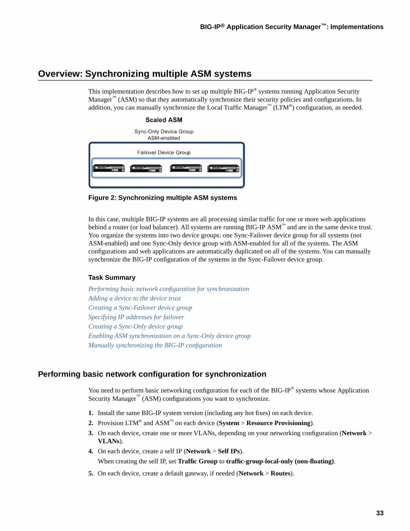
This implementation describes how to set up multiple BIG-IP® systems running Application SecurityManager™ (ASM) so that they automatically synchronize their security policies and configurations. Inaddition, you can manually synchronize the Local Traffic Manager™ (LTM®) configuration, as needed.
Figure 2: Synchronizing multiple ASM systems
In this case, multiple BIG-IP systems are all processing similar traffic for one or more web applicationsbehind a router (or load balancer). All systems are running BIG-IP ASM™ and are in the same device trust.You organize the systems into two device groups: one Sync-Failover device group for all systems (notASM-enabled) and one Sync-Only device group with ASM-enabled for all of the systems. The ASMconfigurations and web applications are automatically duplicated on all of the systems. You can manuallysynchronize the BIG-IP configuration of the systems in the Sync-Failover device group.
Task Summary
Performing basic network configuration for synchronization
Adding a device to the device trust
Creating a Sync-Failover device group
Specifying IP addresses for failover
Creating a Sync-Only device group
Enabling ASM synchronization on a Sync-Only device group
Manually synchronizing the BIG-IP configuration
Performing basic network configuration for synchronization
You need to perform basic networking configuration for each of the BIG-IP® systems whose ApplicationSecurity Manager™ (ASM) configurations you want to synchronize.
1. Install the same BIG-IP system version (including any hot fixes) on each device.
2. Provision LTM® and ASM™ on each device (System > Resource Provisioning).
3. On each device, create one or more VLANs, depending on your networking configuration (Network >VLANs).
4. On each device, create a self IP (Network > Self IPs).
When creating the self IP, set Traffic Group to traffic-group-local-only (non-floating).
5. On each device, create a default gateway, if needed (Network > Routes).
33
BIG-IP® Application Security Manager™: Implementations
6. On each device, configure DNS (System > Configuration > Device > DNS) and NTP (System >Configuration > Device > NTP) so they are set to the same time.
7. Verify connectivity between the devices (self IP address to self IP address). For example, use thiscommand to ensure communications: ping -I vlan_interface device_self_IP
8. On each device, specify the IP address to use when synchronizing configuration objects to the localdevice:
a) Click Device Management > Devices.b) Click the name of the local device.c) From the Device Connectivity menu, choose ConfigSync.d) For the Local Address setting, select the self IP address.e) Click Save Changes.
9. If your company requires special device certificates, install them on each device (System > DeviceCertificates and click Import).
The basic networking setup is complete for the BIG-IP ASM systems for which you want to share securitypolicies and configurations.
Adding a device to the device trust
Establish lines of communication between the BIG-IP® systems for which you want to synchronize securitypolicies and configurations by adding those systems to a device trust. You do this task on only one of thesystems.
1. On the Main tab, click Device Management > Device Trust > Local Domain.
2. In the Peer Authority Devices area of the screen, click Add.
3. Type an IP address, administrator user name, and administrator password for the remote BIG-IP® device.
This IP address can be either a management IP address or a self IP address.
4. Click Next.
5. Verify that the certificate of the remote device is correct.
6. Click Next.
7. Verify that the name of the remote device is correct.
8. Click Next.
9. Verify that the management IP address and name of the remote device are correct.
10. Click Next.
11. Confirm the new device trust: recheck the IP address and name, then click Finished.The system creates the trust domain and adds the devices to the Peer Authority Devices list. The truststatus of the devices is In Sync.
The BIG-IP ASM™ systems that you want to share security policies and configurations are now part of adevice trust.
Creating a Sync-Failover device group
This task establishes failover capability between two or more BIG-IP devices. If the active device in aSync-Failover device group becomes unavailable, the configuration objects fail over to another member ofthe device group and traffic processing is unaffected. You can perform this task on any authority devicewithin the local trust domain.
1. On the Main tab, click Device Management > Device Groups.
34
Synchronizing Application Security Configurations
The Device Groups screen displays a list of existing device groups.
2. On the Device Group List screen, click Create.
3. Type a name for the device group, select the device group type Sync-Failover, and type a descriptionfor the device group.
4. In the Configuration area of the screen, select a host name from the Available list for each BIG-IP devicethat you want to include in the device group. Use the Move button to move the host name to the Selectedlist.
The Available list shows any devices that are members of the device's local trust domain but not currentlymembers of a Sync-Failover device group. A device can be a member of one Sync-Failover group only.
5. For Network Failover, select the Enabled check box.
6. Click Finished.
You now have a Sync-Failover type of device group containing BIG-IP devices as members.
Specifying IP addresses for failover
This task specifies the local IP addresses that you want other devices in the device group to use for failovercommunications with the local device. You must perform this task on each device in the device group.
Note: The failover addresses that you specify must belong to route domain 0.
1. Confirm that you are logged in to the actual device you want to configure.
2. On the Main tab, click Device Management > Devices.This displays a list of device objects discovered by the local device.
3. In the Name column, click the name of the device to which you are currently logged in.
4. From the Device Connectivity menu, choose Failover.
5. For the Failover Unicast Configuration settings, retain the displayed IP addresses.
You can also click Add to specify additional IP addresses that the system can use for failovercommunications. F5 Networks recommends that you use the self IP address assigned to the HAVLAN.
6. If the BIG-IP® system is running on a VIPRION® platform, then for the Use Failover Multicast Addresssetting, select the Enabled check box.
7. If you enable Use Failover Multicast Address, either accept the default Address and Port values, orspecify values appropriate for the device.
If you revise the default Address and Port values, but then decide to revert back to the default values,click Reset Defaults.
8. Click Update.
After you perform this task, other devices in the device group can send failover messages to the local deviceusing the specified IP addresses.
Creating a Sync-Only device group
Follow these steps to create a Sync-Only type of device group. You can perform this task on any BIG-IP®
device within the local trust domain.
1. On the Main tab, click Device Management > Device Groups.The Device Groups screen displays a list of existing device groups.
2. On the Device Group List screen, click Create.
35
BIG-IP® Application Security Manager™: Implementations
3. Type a name for the device group, select the device group type Sync-Only, and type a description forthe device group.
4. Select an IP address and host name from the Available list for each BIG-IP device that you want toinclude in the device group. Use the Move button to move the host name to the Includes list.
The list shows any devices that are members of the device's local trust domain.
5. For Automatic Sync, select the Enabled check box.
6. Click Finished.
You now have a Sync-Only type of device group containing BIG-IP devices as members.
Enabling ASM synchronization on a Sync-Only device group
You need to have set up the BIG-IP®systems you want to synchronize in a device trust and a device group.Application Security Manager™ (ASM) must be provisioned on all the systems in the device group.
You can enable ASM™ synchronization on a device group to synchronize security policies and configurationson all devices in the device group. You do this task on one system, for example, the active system in anactive/standby pair.
1. On the Main tab, click Application Security > Synchronization.The system displays a list of device groups of which this device is a member.
2. For Device Group, select the Sync-Only device group you created.
3. Click Save.
The BIG-IP ASM™ systems that you want to share security policies and configurations are part of a Sync-Onlydevice group with ASM synchronization.
Manually synchronizing the BIG-IP configuration
You can manually synchronize the BIG-IP® configuration to or from other device group members. Todetermine if a manual config sync is necessary, you can list the members of the device group and view thesynchronization status of each member.
Note: When synchronizing self IP addresses, the BIG-IP system synchronizes floating self IPaddresses only. Static self IP addresses are not synchronized. Also, for Sync-Only device groups,you can configure automatic synchronization.
1. On the Main tab, click Device Management > Device Groups.The Device Groups screen displays a list of existing device groups.
2. In the Group Name column, click the name of the relevant device group.
3. On the menu bar, click ConfigSync.
4. Determine which option to select for synchronization.
DescriptionOption
Synchronizes the configuration data on the local device to alldevice group members.
Synchronize To Group
Synchronizes the configuration data on other device groupmembers to the local member.
Synchronize From Group
36
Synchronizing Application Security Configurations
Except for static self IP addresses, the entire set of BIG-IP configuration data is replicated on each devicein the device group.
Result: Synchronizing multiple ASM systems
You have set up multiple BIG-IP® systems running Application Security Manager™ (ASM) so that theyautomatically synchronize their security policies and configurations. In addition, you can manuallysynchronize the Local Traffic Manager™ (LTM®) configuration, as needed.
You can create new security policies or update existing ones on any of the devices in the group, or updatethe ASM™ configuration options. Any ASM changes you make on one device are automatically synchronizedwith the other devices in the ASM-enabled Sync-Only device group.
If Attack Signatures Update Mode is scheduled for automatic update, the attack signature update settingsare synchronized. Each device in the device group updates itself independently according to the configuredschedule. If you manually upload attack signatures or click Update Signatures to update from the server,the update is propagated to all of the devices in the device group.
Overview: Synchronizing ASM systems for disaster recovery
This implementation describes how to set up multiple BIG-IP® systems running Application SecurityManager™ (ASM) so that you can synchronize their security policies and configurations for disaster recovery.You could use this implementation to back up BIG-IP ASM™ security policies and configurations on systemsresiding in different network segments or LANs, such as those in separate offices or data centers. Note thattraffic must be routable between the network segments. If a disaster occurs at one of the offices and bothdevices are disabled, the latest security policies are still available on the systems in the other location.
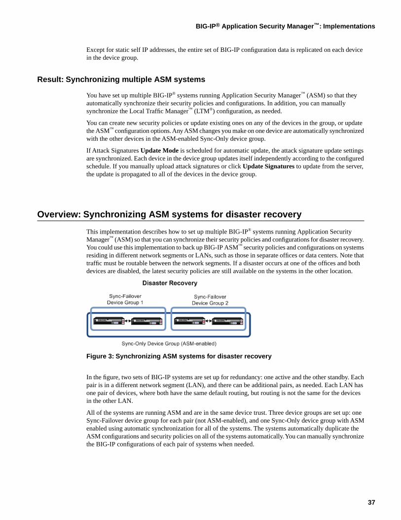
Figure 3: Synchronizing ASM systems for disaster recovery
In the figure, two sets of BIG-IP systems are set up for redundancy: one active and the other standby. Eachpair is in a different network segment (LAN), and there can be additional pairs, as needed. Each LAN hasone pair of devices, where both have the same default routing, but routing is not the same for the devicesin the other LAN.
All of the systems are running ASM and are in the same device trust. Three device groups are set up: oneSync-Failover device group for each pair (not ASM-enabled), and one Sync-Only device group with ASMenabled using automatic synchronization for all of the systems. The systems automatically duplicate theASM configurations and security policies on all of the systems automatically. You can manually synchronizethe BIG-IP configurations of each pair of systems when needed.
37
BIG-IP® Application Security Manager™: Implementations
Task Summary
Performing basic network configuration for synchronization
Adding a device to the device trust
Creating a Sync-Failover device group
Specifying IP addresses for failover
Creating a Sync-Only device group
Enabling ASM synchronization on a Sync-Only device group
Manually synchronizing the BIG-IP configuration
Performing basic network configuration for synchronization
You need to perform basic networking configuration for each of the BIG-IP® systems whose ApplicationSecurity Manager™ (ASM) configurations you want to synchronize.
1. Install the same BIG-IP system version (including any hot fixes) on each device.
2. Provision LTM® and ASM™ on each device (System > Resource Provisioning).
3. On each device, create one or more VLANs, depending on your networking configuration (Network >VLANs).
4. On each device, create a self IP (Network > Self IPs).
When creating the self IP, set Traffic Group to traffic-group-local-only (non-floating).
5. On each device, create a default gateway, if needed (Network > Routes).
6. On each device, configure DNS (System > Configuration > Device > DNS) and NTP (System >Configuration > Device > NTP) so they are set to the same time.
7. Verify connectivity between the devices (self IP address to self IP address). For example, use thiscommand to ensure communications: ping -I vlan_interface device_self_IP
8. On each device, specify the IP address to use when synchronizing configuration objects to the localdevice:
a) Click Device Management > Devices.b) Click the name of the local device.c) From the Device Connectivity menu, choose ConfigSync.d) For the Local Address setting, select the self IP address.e) Click Save Changes.
9. If your company requires special device certificates, install them on each device (System > DeviceCertificates and click Import).
The basic networking setup is complete for the BIG-IP ASM systems for which you want to share securitypolicies and configurations.
Adding a device to the device trust
Establish lines of communication between the BIG-IP® systems for which you want to synchronize securitypolicies and configurations by adding those systems to a device trust. You do this task on only one of thesystems.
1. On the Main tab, click Device Management > Device Trust > Local Domain.
2. In the Peer Authority Devices area of the screen, click Add.
3. Type an IP address, administrator user name, and administrator password for the remote BIG-IP® device.
38
Synchronizing Application Security Configurations
This IP address can be either a management IP address or a self IP address.
4. Click Next.
5. Verify that the certificate of the remote device is correct.
6. Click Next.
7. Verify that the name of the remote device is correct.
8. Click Next.
9. Verify that the management IP address and name of the remote device are correct.
10. Click Next.
11. Confirm the new device trust: recheck the IP address and name, then click Finished.The system creates the trust domain and adds the devices to the Peer Authority Devices list. The truststatus of the devices is In Sync.
The BIG-IP ASM™ systems that you want to share security policies and configurations are now part of adevice trust.
Creating a Sync-Failover device group
Devices that you want to add to a device group must already be in a device trust.
Perform this procedure to create a Sync-Failover device group for each office or data center in which youwant an active and standby BIG-IP® system. You can perform this task on any authority device within thelocal trust domain.
1. On the Main tab, click Device Management > Device Groups.The Device Groups screen displays a list of existing device groups.
2. On the Device Group List screen, click Create.
3. Type a name for the device group, select the device group type Sync-Failover, and type a descriptionfor the device group.
4. Click Next.
5. In the Configuration area of the screen, select a host name from the Available list for each BIG-IP devicethat you want to include in the device group. Use the Move button to move the host name to the Selectedlist.
The Available list shows any devices that are members of the device's local trust domain but not currentlymembers of a Sync-Failover device group. A device can be a member of one Sync-Failover group only.
6. Click Next.
7. For Network Failover, select the Enabled check box.
8. Click Next.
9. Click Finished.
You now have a Sync-Failover device group containing BIG-IP devices as members.
Next, you need to specify IP addresses for failover.
Specifying IP addresses for failover
This task specifies the local IP addresses that you want other devices in the device group to use for failovercommunications with the local device. You must perform this task on each device in the device group.
Note: The failover addresses that you specify must belong to route domain 0.
39
BIG-IP® Application Security Manager™: Implementations
1. Confirm that you are logged in to the actual device you want to configure.
2. On the Main tab, click Device Management > Devices.This displays a list of device objects discovered by the local device.
3. In the Name column, click the name of the device to which you are currently logged in.
4. From the Device Connectivity menu, choose Failover.
5. For the Failover Unicast Configuration settings, retain the displayed IP addresses.
You can also click Add to specify additional IP addresses that the system can use for failovercommunications. F5 Networks recommends that you use the self IP address assigned to the HAVLAN.
6. If the BIG-IP® system is running on a VIPRION® platform, then for the Use Failover Multicast Addresssetting, select the Enabled check box.
7. If you enable Use Failover Multicast Address, either accept the default Address and Port values, orspecify values appropriate for the device.
If you revise the default Address and Port values, but then decide to revert back to the default values,click Reset Defaults.
8. Click Update.
After you perform this task, other devices in the device group can send failover messages to the local deviceusing the specified IP addresses.
Creating a Sync-Only device group
Follow these steps to create a Sync-Only type of device group. You can perform this task on any BIG-IP®
device within the local trust domain.
1. On the Main tab, click Device Management > Device Groups.The Device Groups screen displays a list of existing device groups.
2. On the Device Group List screen, click Create.
3. Type a name for the device group, select the device group type Sync-Only, and type a description forthe device group.
4. Select an IP address and host name from the Available list for each BIG-IP device that you want toinclude in the device group. Use the Move button to move the host name to the Includes list.
The list shows any devices that are members of the device's local trust domain.
5. For Automatic Sync, select the Enabled check box.
6. Click Finished.
You now have a Sync-Only type of device group containing BIG-IP devices as members.
Enabling ASM synchronization on a Sync-Only device group
You need to have set up the BIG-IP®systems you want to synchronize in a device trust and a device group.Application Security Manager™ (ASM) must be provisioned on all the systems in the device group.
You can enable ASM™ synchronization on a device group to synchronize security policies and configurationson all devices in the device group. You do this task on one system, for example, the active system in anactive/standby pair.
1. On the Main tab, click Application Security > Synchronization.The system displays a list of device groups of which this device is a member.
2. For Device Group, select the Sync-Only device group you created.
40
Synchronizing Application Security Configurations
3. Click Save.
The BIG-IP ASM™ systems that you want to share security policies and configurations are part of a Sync-Onlydevice group with ASM synchronization.
Manually synchronizing the BIG-IP configuration
You can manually synchronize the BIG-IP® configuration to or from other device group members. Todetermine if a manual config sync is necessary, you can list the members of the device group and view thesynchronization status of each member.
Note: When synchronizing self IP addresses, the BIG-IP system synchronizes floating self IPaddresses only. Static self IP addresses are not synchronized. Also, for Sync-Only device groups,you can configure automatic synchronization.
1. On the Main tab, click Device Management > Device Groups.The Device Groups screen displays a list of existing device groups.
2. In the Group Name column, click the name of the relevant device group.
3. On the menu bar, click ConfigSync.
4. Determine which option to select for synchronization.
DescriptionOption
Synchronizes the configuration data on the local device to alldevice group members.
Synchronize To Group
Synchronizes the configuration data on other device groupmembers to the local member.
Synchronize From Group
Except for static self IP addresses, the entire set of BIG-IP configuration data is replicated on each devicein the device group.
Result: Synchronizing ASM systems for disaster recovery
You have set up disaster recovery for multiple BIG-IP® systems running Application Security Manager™
(ASM). Each office or data center has an active system and a standby that takes over if the active systemshould fail. You must manually synchronize the BIG-IP configuration from one system to the other if youchange the configuration.
You can create new security policies or update existing ones on any of the devices in the group, or updatethe ASM™ configuration options (Application Security>Options). Any changes you make on one deviceare automatically synchronized with the other devices in the ASM-enabled Sync-Only device group.
If Attack Signatures Update Mode is scheduled for automatic update, the attack signature update settingsare synchronized. Each device in the device group updates itself independently according to the configuredschedule. If you manually upload attack signatures or click Upload Signatures to update from the server,the update is propagated to all of the devices in the device group.
41
BIG-IP® Application Security Manager™: Implementations

42
Synchronizing Application Security Configurations
Chapter
5
Configuring Application Security Session Tracking
Topics:
• Overview: Tracking application securitysessions using login pages
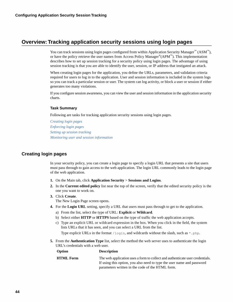
Overview:Tracking application security sessions using login pages
You can track sessions using login pages configured from within Application Security Manager™ (ASM™),or have the policy retrieve the user names from Access Policy Manager®(APM™). This implementationdescribes how to set up session tracking for a security policy using login pages. The advantage of usingsession tracking is that you are able to identify the user, session, or IP address that instigated an attack.
When creating login pages for the application, you define the URLs, parameters, and validation criteriarequired for users to log in to the application. User and session information is included in the system logsso you can track a particular session or user. The system can log activity, or block a user or session if eithergenerates too many violations.
If you configure session awareness, you can view the user and session information in the application securitycharts.
Task Summary
Following are tasks for tracking application security sessions using login pages.
Creating login pages
Enforcing login pages
Setting up session tracking
Monitoring user and session information
Creating login pages
In your security policy, you can create a login page to specify a login URL that presents a site that usersmust pass through to gain access to the web application. The login URL commonly leads to the login pageof the web application.
1. On the Main tab, click Application Security > Sessions and Logins.
2. In the Current edited policy list near the top of the screen, verify that the edited security policy is theone you want to work on.
3. Click Create.The New Login Page screen opens.
4. For the Login URL setting, specify a URL that users must pass through to get to the application.
a) From the list, select the type of URL: Explicit or Wildcard.b) Select either HTTP or HTTPS based on the type of traffic the web application accepts.c) Type an explicit URL or wildcard expression in the box. When you click in the field, the system
lists URLs that it has seen, and you can select a URL from the list.
Type explicit URLs in the format /login, and wildcards without the slash, such as *.php.
5. From the Authentication Type list, select the method the web server uses to authenticate the loginURL’s credentials with a web user.
DescriptionOption
The web application uses a form to collect and authenticate user credentials.If using this option, you also need to type the user name and passwordparameters written in the code of the HTML form.
HTML Form
44
Configuring Application Security Session Tracking
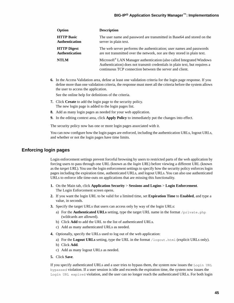
DescriptionOption
The user name and password are transmitted in Base64 and stored on theserver in plain text.
HTTP BasicAuthentication
The web server performs the authentication; user names and passwordsare not transmitted over the network, nor are they stored in plain text.
HTTP DigestAuthentication
Microsoft® LAN Manager authentication (also called Integrated WindowsAuthentication) does not transmit credentials in plain text, but requires acontinuous TCP connection between the server and client.
NTLM
6. In the Access Validation area, define at least one validation criteria for the login page response. If youdefine more than one validation criteria, the response must meet all the criteria before the system allowsthe user to access the application.
See the online help for definitions of the criteria.
7. Click Create to add the login page to the security policy.The new login page is added to the login pages list.
8. Add as many login pages as needed for your web application.
9. In the editing context area, click Apply Policy to immediately put the changes into effect.
The security policy now has one or more login pages associated with it.
You can now configure how the login pages are enforced, including the authentication URLs, logout URLs,and whether or not the login pages have time limits.
Enforcing login pages
Login enforcement settings prevent forceful browsing by users to restricted parts of the web application byforcing users to pass through one URL (known as the login URL) before viewing a different URL (knownas the target URL). You use the login enforcement settings to specify how the security policy enforces loginpages including the expiration time, authenticated URLs, and logout URLs. You can also use authenticatedURLs to enforce idle time-outs on applications that are missing this functionality.
1. On the Main tab, click Application Security > Sessions and Logins > Login Enforcement.The Login Enforcement screen opens.
2. If you want the login URL to be valid for a limited time, set Expiration Time to Enabled, and type avalue, in seconds.
3. Specify the target URLs that users can access only by way of the login URLs:
a) For the Authenticated URLs setting, type the target URL name in the format /private.php(wildcards are allowed).
b) Click Add to add the URL to the list of authenticated URLs.c) Add as many authenticated URLs as needed.
4. Optionally, specify the URLs used to log out of the web application:
a) For the Logout URLs setting, type the URL in the format /logout.html (explicit URLs only).b) Click Add.c) Add as many logout URLs as needed.
5. Click Save.
If you specify authenticated URLs and a user tries to bypass them, the system now issues the Login URLbypassed violation. If a user session is idle and exceeds the expiration time, the system now issues theLogin URL expired violation, and the user can no longer reach the authenticated URLs. For both login
45
BIG-IP® Application Security Manager™: Implementations
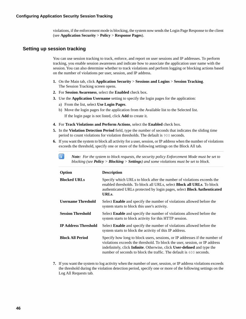
violations, if the enforcement mode is blocking, the system now sends the Login Page Response to the client(see Application Security > Policy > Response Pages).
Setting up session tracking
You can use session tracking to track, enforce, and report on user sessions and IP addresses. To performtracking, you enable session awareness and indicate how to associate the application user name with thesession. You can also determine whether to track violations and perform logging or blocking actions basedon the number of violations per user, session, and IP address.
1. On the Main tab, click Application Security > Sessions and Logins > Session Tracking.The Session Tracking screen opens.
2. For Session Awareness, select the Enabled check box.
3. Use the Application Username setting to specify the login pages for the application:
a) From the list, select Use Login Pages.b) Move the login pages for the application from the Available list to the Selected list.
If the login page is not listed, click Add to create it.
4. For Track Violations and Perform Actions, select the Enabled check box.
5. In the Violation Detection Period field, type the number of seconds that indicates the sliding timeperiod to count violations for violation thresholds. The default is 900 seconds.
6. If you want the system to block all activity for a user, session, or IP address when the number of violationsexceeds the threshold, specify one or more of the following settings on the Block All tab.
Note: For the system to block requests, the security policy Enforcement Mode must be set toblocking (see Policy > Blocking > Settings) and some violations must be set to block.
DescriptionOption
Specify which URLs to block after the number of violations exceeds theenabled thresholds. To block all URLs, select Block all URLs. To block
Blocked URLs
authenticated URLs protected by login pages, select Block AuthenticatedURLs.
Select Enable and specify the number of violations allowed before thesystem starts to block this user's activity.
Username Threshold
Select Enable and specify the number of violations allowed before thesystem starts to block activity for this HTTP session.
Session Threshold
Select Enable and specify the number of violations allowed before thesystem starts to block the activity of this IP address.
IP Address Threshold
Specify how long to block users, sessions, or IP addresses if the number ofviolations exceeds the threshold. To block the user, session, or IP address
Block All Period
indefinitely, click Infinite. Otherwise, click User-defined and type thenumber of seconds to block the traffic. The default is 600 seconds.
7. If you want the system to log activity when the number of user, session, or IP address violations exceedsthe threshold during the violation detection period, specify one or more of the following settings on theLog All Requests tab.
46
Configuring Application Security Session Tracking
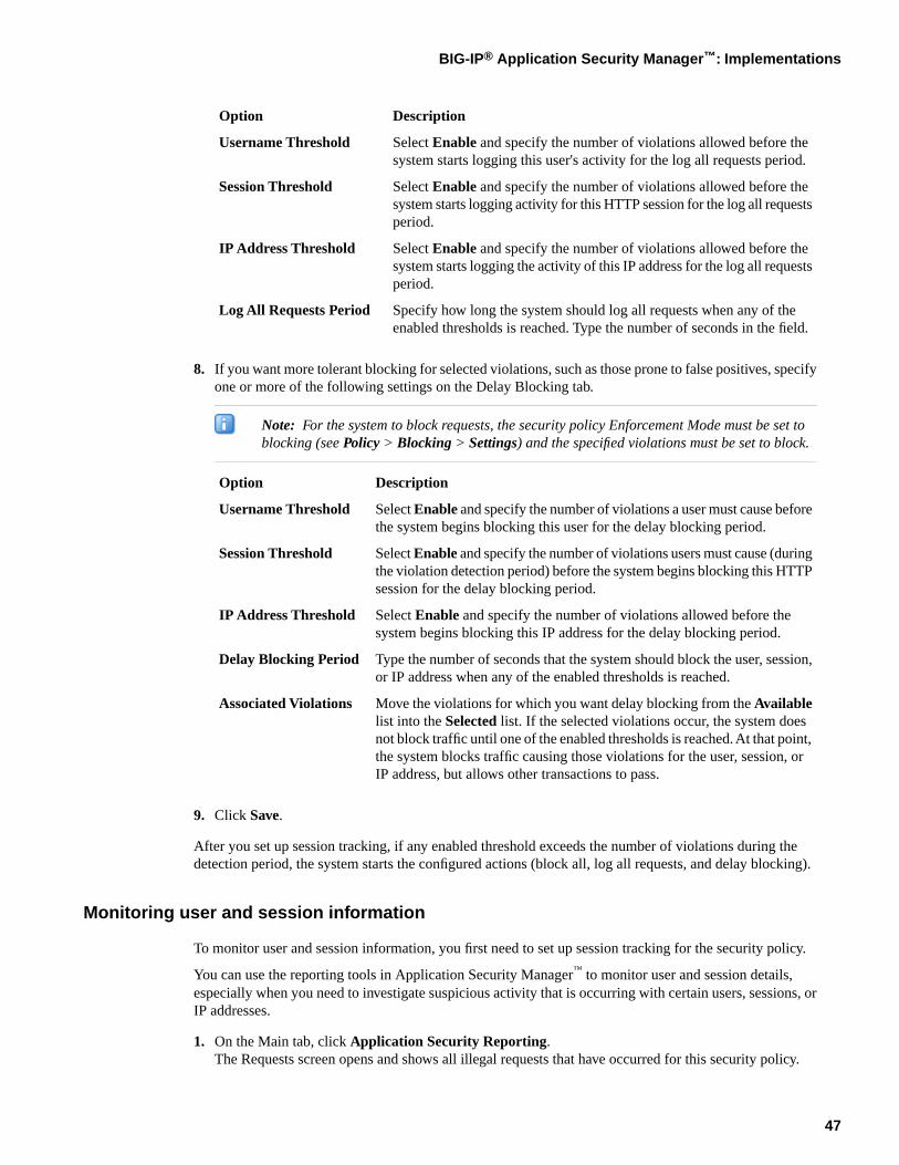
DescriptionOption
Select Enable and specify the number of violations allowed before thesystem starts logging this user's activity for the log all requests period.
Username Threshold
Select Enable and specify the number of violations allowed before thesystem starts logging activity for this HTTP session for the log all requestsperiod.
Session Threshold
Select Enable and specify the number of violations allowed before thesystem starts logging the activity of this IP address for the log all requestsperiod.
IP Address Threshold
Specify how long the system should log all requests when any of theenabled thresholds is reached. Type the number of seconds in the field.
Log All Requests Period
8. If you want more tolerant blocking for selected violations, such as those prone to false positives, specifyone or more of the following settings on the Delay Blocking tab.
Note: For the system to block requests, the security policy Enforcement Mode must be set toblocking (see Policy > Blocking > Settings) and the specified violations must be set to block.
DescriptionOption
Select Enable and specify the number of violations a user must cause beforethe system begins blocking this user for the delay blocking period.
Username Threshold
Select Enable and specify the number of violations users must cause (duringthe violation detection period) before the system begins blocking this HTTPsession for the delay blocking period.
Session Threshold
Select Enable and specify the number of violations allowed before thesystem begins blocking this IP address for the delay blocking period.
IP Address Threshold
Type the number of seconds that the system should block the user, session,or IP address when any of the enabled thresholds is reached.
Delay Blocking Period
Move the violations for which you want delay blocking from the Availablelist into the Selected list. If the selected violations occur, the system does
Associated Violations
not block traffic until one of the enabled thresholds is reached. At that point,the system blocks traffic causing those violations for the user, session, orIP address, but allows other transactions to pass.
9. Click Save.
After you set up session tracking, if any enabled threshold exceeds the number of violations during thedetection period, the system starts the configured actions (block all, log all requests, and delay blocking).
Monitoring user and session information
To monitor user and session information, you first need to set up session tracking for the security policy.
You can use the reporting tools in Application Security Manager™ to monitor user and session details,especially when you need to investigate suspicious activity that is occurring with certain users, sessions, orIP addresses.
1. On the Main tab, click Application Security Reporting.The Requests screen opens and shows all illegal requests that have occurred for this security policy.
47
BIG-IP® Application Security Manager™: Implementations
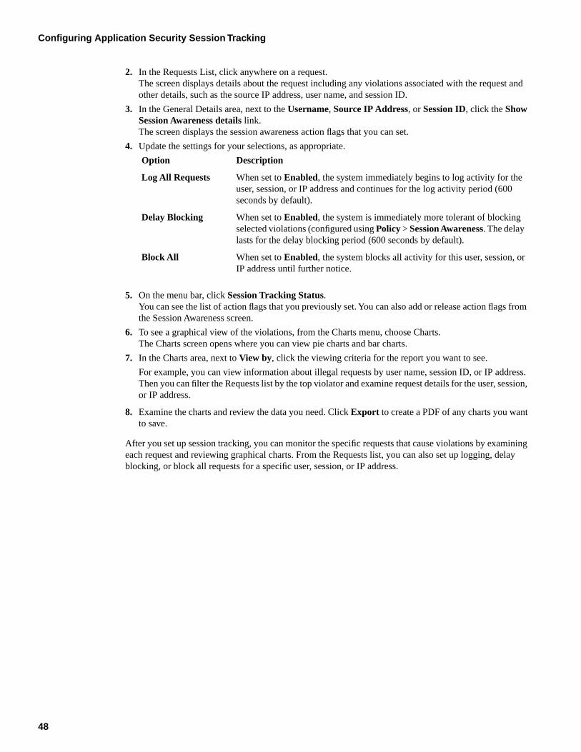
2. In the Requests List, click anywhere on a request.The screen displays details about the request including any violations associated with the request andother details, such as the source IP address, user name, and session ID.
3. In the General Details area, next to the Username, Source IP Address, or Session ID, click the ShowSession Awareness details link.The screen displays the session awareness action flags that you can set.
4. Update the settings for your selections, as appropriate.
DescriptionOption
When set to Enabled, the system immediately begins to log activity for theuser, session, or IP address and continues for the log activity period (600seconds by default).
Log All Requests
When set to Enabled, the system is immediately more tolerant of blockingselected violations (configured using Policy > Session Awareness. The delaylasts for the delay blocking period (600 seconds by default).
Delay Blocking
When set to Enabled, the system blocks all activity for this user, session, orIP address until further notice.
Block All
5. On the menu bar, click Session Tracking Status.You can see the list of action flags that you previously set. You can also add or release action flags fromthe Session Awareness screen.
6. To see a graphical view of the violations, from the Charts menu, choose Charts.The Charts screen opens where you can view pie charts and bar charts.
7. In the Charts area, next to View by, click the viewing criteria for the report you want to see.
For example, you can view information about illegal requests by user name, session ID, or IP address.Then you can filter the Requests list by the top violator and examine request details for the user, session,or IP address.
8. Examine the charts and review the data you need. Click Export to create a PDF of any charts you wantto save.
After you set up session tracking, you can monitor the specific requests that cause violations by examiningeach request and reviewing graphical charts. From the Requests list, you can also set up logging, delayblocking, or block all requests for a specific user, session, or IP address.
48
Configuring Application Security Session Tracking
Chapter
6
Tracking Application Security Sessions with APM
Topics:
• Overview: Tracking application securitysessions using APM
• Prerequisites for setting up session trackingwith APM
Overview:Tracking application security sessions using APM
You can track sessions using login pages configured from within Application Security Manager™ (ASM™),or have the policy retrieve the user names from Access Policy Manager®(APM™). This implementationdescribes how to set up session tracking for a security policy using APM to verify user credentials. Then,you can set up session awareness from within ASM to identify the user, session, or IP address that instigatedan attack.
If you configure session tracking, you can view the user and session information in the application securitycharts.
Prerequisites for setting up session tracking with APM
In order to set up session tracking from within Application Security Manager™ (ASM™) so that the securitypolicy retrieves the user names from Access Policy Manager ®(APM™), you need to perform basic thesesystem configuration tasks according to the needs of your networking configuration:
• Run the setup utility and create a management IP address.• License and provision ASM, APM, and Local Traffic Manager™ (LTM™).• Configure a DNS address (System > Configuration > Device > DNS).• Configure an NTP server (System > Configuration > Device > NTP).• Restart ASM (at the command line, type tmsh restart /sys service asm).
If you need more information about basic networking configuration on the BIG-IP® system, refer to theBIG-IP documentation.
Task summary
Use the following tasks to set up application security session tracking with APM authentication integrated.
Creating a VLAN
Creating a self IP address for a VLAN
Creating a local traffic pool for application security
Creating an HTTP class
Creating a virtual server to manage HTTPS traffic
Creating a security policy automatically
Creating an access profile
Configuring an access policy
Adding the access profile to the virtual server
Setting up ASM session tracking with APM
Monitoring user and session information
Creating a VLAN
VLANs represent a collection of hosts that can share network resources, regardless of their physical locationon the network.
50
Tracking Application Security Sessions with APM
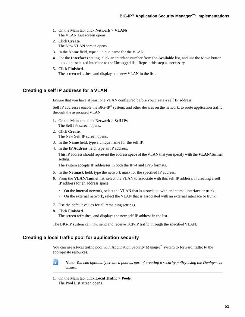
1. On the Main tab, click Network > VLANs.The VLAN List screen opens.
2. Click Create.The New VLAN screen opens.
3. In the Name field, type a unique name for the VLAN.
4. For the Interfaces setting, click an interface number from the Available list, and use the Move buttonto add the selected interface to the Untagged list. Repeat this step as necessary.
5. Click Finished.The screen refreshes, and displays the new VLAN in the list.
Creating a self IP address for a VLAN
Ensure that you have at least one VLAN configured before you create a self IP address.
Self IP addresses enable the BIG-IP® system, and other devices on the network, to route application trafficthrough the associated VLAN.
1. On the Main tab, click Network > Self IPs.The Self IPs screen opens.
2. Click Create.The New Self IP screen opens.
3. In the Name field, type a unique name for the self IP.
4. In the IP Address field, type an IP address.
This IP address should represent the address space of the VLAN that you specify with the VLAN/Tunnelsetting.
The system accepts IP addresses in both the IPv4 and IPv6 formats.
5. In the Netmask field, type the network mask for the specified IP address.
6. From the VLAN/Tunnel list, select the VLAN to associate with this self IP address. If creating a selfIP address for an address space:
• On the internal network, select the VLAN that is associated with an internal interface or trunk.• On the external network, select the VLAN that is associated with an external interface or trunk.
7. Use the default values for all remaining settings.
8. Click Finished.The screen refreshes, and displays the new self IP address in the list.
The BIG-IP system can now send and receive TCP/IP traffic through the specified VLAN.
Creating a local traffic pool for application security
You can use a local traffic pool with Application Security Manager™ system to forward traffic to theappropriate resources.
Note: You can optionally create a pool as part of creating a security policy using the Deploymentwizard.
1. On the Main tab, click Local Traffic > Pools.The Pool List screen opens.
51
BIG-IP® Application Security Manager™: Implementations
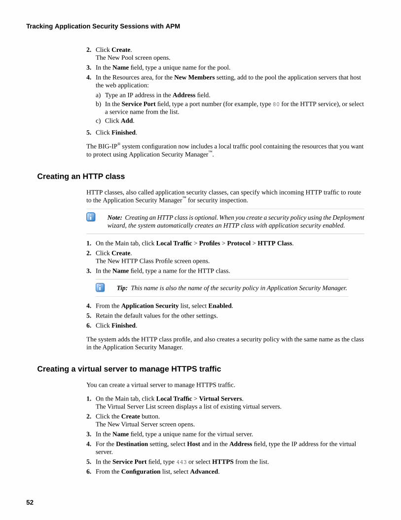
2. Click Create.The New Pool screen opens.
3. In the Name field, type a unique name for the pool.
4. In the Resources area, for the New Members setting, add to the pool the application servers that hostthe web application:
a) Type an IP address in the Address field.b) In the Service Port field, type a port number (for example, type 80 for the HTTP service), or select
a service name from the list.c) Click Add.
5. Click Finished.
The BIG-IP® system configuration now includes a local traffic pool containing the resources that you wantto protect using Application Security Manager™.
Creating an HTTP class
HTTP classes, also called application security classes, can specify which incoming HTTP traffic to routeto the Application Security Manager™ for security inspection.
Note: Creating an HTTP class is optional. When you create a security policy using the Deploymentwizard, the system automatically creates an HTTP class with application security enabled.
1. On the Main tab, click Local Traffic > Profiles > Protocol > HTTP Class.
2. Click Create.The New HTTP Class Profile screen opens.
3. In the Name field, type a name for the HTTP class.
Tip: This name is also the name of the security policy in Application Security Manager.
4. From the Application Security list, select Enabled.
5. Retain the default values for the other settings.
6. Click Finished.
The system adds the HTTP class profile, and also creates a security policy with the same name as the classin the Application Security Manager.
Creating a virtual server to manage HTTPS traffic
You can create a virtual server to manage HTTPS traffic.
1. On the Main tab, click Local Traffic > Virtual Servers.The Virtual Server List screen displays a list of existing virtual servers.
2. Click the Create button.The New Virtual Server screen opens.
3. In the Name field, type a unique name for the virtual server.
4. For the Destination setting, select Host and in the Address field, type the IP address for the virtualserver.
5. In the Service Port field, type 443 or select HTTPS from the list.
6. From the Configuration list, select Advanced.
52
Tracking Application Security Sessions with APM
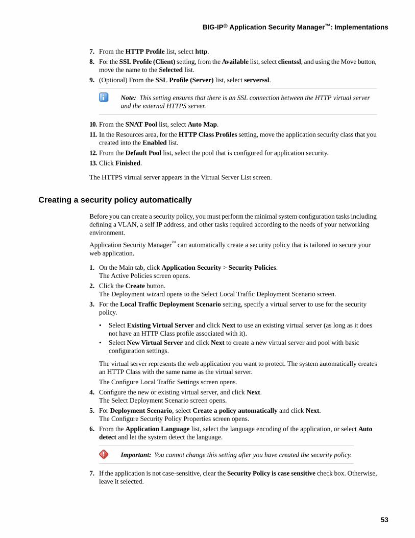
7. From the HTTP Profile list, select http.
8. For the SSL Profile (Client) setting, from the Available list, select clientssl, and using the Move button,move the name to the Selected list.
9. (Optional) From the SSL Profile (Server) list, select serverssl.
Note: This setting ensures that there is an SSL connection between the HTTP virtual serverand the external HTTPS server.
10. From the SNAT Pool list, select Auto Map.
11. In the Resources area, for the HTTP Class Profiles setting, move the application security class that youcreated into the Enabled list.
12. From the Default Pool list, select the pool that is configured for application security.
13. Click Finished.
The HTTPS virtual server appears in the Virtual Server List screen.
Creating a security policy automatically
Before you can create a security policy, you must perform the minimal system configuration tasks includingdefining a VLAN, a self IP address, and other tasks required according to the needs of your networkingenvironment.
Application Security Manager™ can automatically create a security policy that is tailored to secure yourweb application.
1. On the Main tab, click Application Security > Security Policies.The Active Policies screen opens.
2. Click the Create button.The Deployment wizard opens to the Select Local Traffic Deployment Scenario screen.
3. For the Local Traffic Deployment Scenario setting, specify a virtual server to use for the securitypolicy.
• Select Existing Virtual Server and click Next to use an existing virtual server (as long as it doesnot have an HTTP Class profile associated with it).
• Select New Virtual Server and click Next to create a new virtual server and pool with basicconfiguration settings.
The virtual server represents the web application you want to protect. The system automatically createsan HTTP Class with the same name as the virtual server.
The Configure Local Traffic Settings screen opens.
4. Configure the new or existing virtual server, and click Next.The Select Deployment Scenario screen opens.
5. For Deployment Scenario, select Create a policy automatically and click Next.The Configure Security Policy Properties screen opens.
6. From the Application Language list, select the language encoding of the application, or select Autodetect and let the system detect the language.
Important: You cannot change this setting after you have created the security policy.
7. If the application is not case-sensitive, clear the Security Policy is case sensitive check box. Otherwise,leave it selected.
53
BIG-IP® Application Security Manager™: Implementations
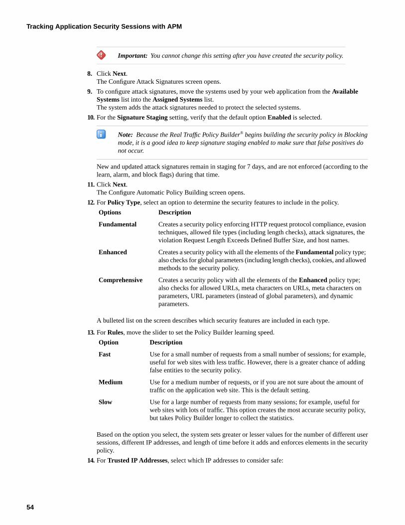
Important: You cannot change this setting after you have created the security policy.
8. Click Next.The Configure Attack Signatures screen opens.
9. To configure attack signatures, move the systems used by your web application from the AvailableSystems list into the Assigned Systems list.The system adds the attack signatures needed to protect the selected systems.
10. For the Signature Staging setting, verify that the default option Enabled is selected.
Note: Because the Real Traffic Policy Builder® begins building the security policy in Blockingmode, it is a good idea to keep signature staging enabled to make sure that false positives donot occur.
New and updated attack signatures remain in staging for 7 days, and are not enforced (according to thelearn, alarm, and block flags) during that time.
11. Click Next.The Configure Automatic Policy Building screen opens.
12. For Policy Type, select an option to determine the security features to include in the policy.
DescriptionOptions
Creates a security policy enforcing HTTP request protocol compliance, evasiontechniques, allowed file types (including length checks), attack signatures, theviolation Request Length Exceeds Defined Buffer Size, and host names.
Fundamental
Creates a security policy with all the elements of the Fundamental policy type;also checks for global parameters (including length checks), cookies, and allowedmethods to the security policy.
Enhanced
Creates a security policy with all the elements of the Enhanced policy type;also checks for allowed URLs, meta characters on URLs, meta characters on
Comprehensive
parameters, URL parameters (instead of global parameters), and dynamicparameters.
A bulleted list on the screen describes which security features are included in each type.
13. For Rules, move the slider to set the Policy Builder learning speed.
DescriptionOption
Use for a small number of requests from a small number of sessions; for example,useful for web sites with less traffic. However, there is a greater chance of addingfalse entities to the security policy.
Fast
Use for a medium number of requests, or if you are not sure about the amount oftraffic on the application web site. This is the default setting.
Medium
Use for a large number of requests from many sessions; for example, useful forweb sites with lots of traffic. This option creates the most accurate security policy,but takes Policy Builder longer to collect the statistics.
Slow
Based on the option you select, the system sets greater or lesser values for the number of different usersessions, different IP addresses, and length of time before it adds and enforces elements in the securitypolicy.
14. For Trusted IP Addresses, select which IP addresses to consider safe:
54
Tracking Application Security Sessions with APM
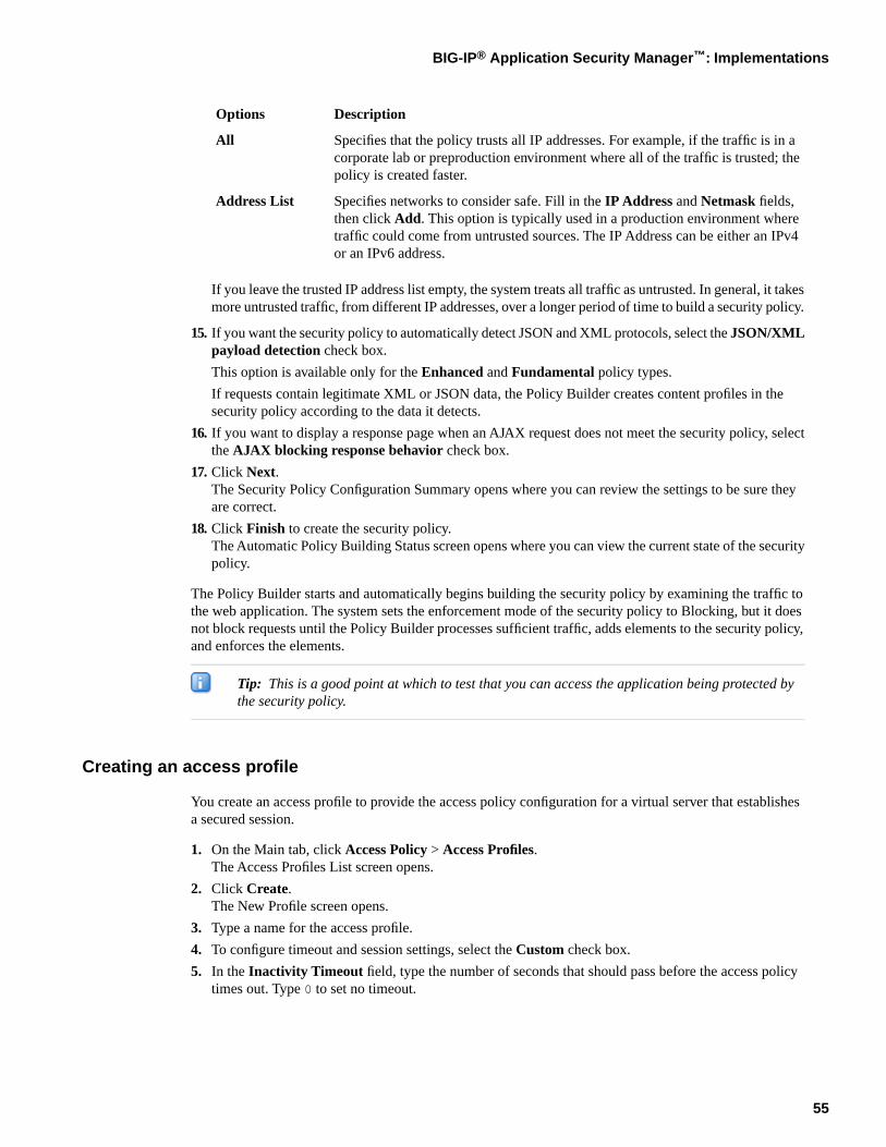
DescriptionOptions
Specifies that the policy trusts all IP addresses. For example, if the traffic is in acorporate lab or preproduction environment where all of the traffic is trusted; thepolicy is created faster.
All
Specifies networks to consider safe. Fill in the IP Address and Netmask fields,then click Add. This option is typically used in a production environment where
Address List
traffic could come from untrusted sources. The IP Address can be either an IPv4or an IPv6 address.
If you leave the trusted IP address list empty, the system treats all traffic as untrusted. In general, it takesmore untrusted traffic, from different IP addresses, over a longer period of time to build a security policy.
15. If you want the security policy to automatically detect JSON and XML protocols, select the JSON/XMLpayload detection check box.
This option is available only for the Enhanced and Fundamental policy types.
If requests contain legitimate XML or JSON data, the Policy Builder creates content profiles in thesecurity policy according to the data it detects.
16. If you want to display a response page when an AJAX request does not meet the security policy, selectthe AJAX blocking response behavior check box.
17. Click Next.The Security Policy Configuration Summary opens where you can review the settings to be sure theyare correct.
18. Click Finish to create the security policy.The Automatic Policy Building Status screen opens where you can view the current state of the securitypolicy.
The Policy Builder starts and automatically begins building the security policy by examining the traffic tothe web application. The system sets the enforcement mode of the security policy to Blocking, but it doesnot block requests until the Policy Builder processes sufficient traffic, adds elements to the security policy,and enforces the elements.
Tip: This is a good point at which to test that you can access the application being protected bythe security policy.
Creating an access profile
You create an access profile to provide the access policy configuration for a virtual server that establishesa secured session.
1. On the Main tab, click Access Policy > Access Profiles.The Access Profiles List screen opens.
2. Click Create.The New Profile screen opens.
3. Type a name for the access profile.
4. To configure timeout and session settings, select the Custom check box.
5. In the Inactivity Timeout field, type the number of seconds that should pass before the access policytimes out. Type 0 to set no timeout.
55
BIG-IP® Application Security Manager™: Implementations
If there is no activity (defined by the Session Update Threshold and Session Update Window settingsin the Network Access configuration) between the client and server within the specified threshold time,the system closes the current session.
6. In the Access Policy Timeout field, type the number of seconds that should pass before the accessprofile times out because of inactivity.
Type 0 to set no timeout.
You must select the associated Custom check box before you can configure this setting.
7. In the Maximum Session Timeout field, type the maximum number of seconds the session can exist.
Type 0 to set no timeout.
You must select the associated Custom check box before you can configure this setting.
8. In the Max Concurrent Users field, type the maximum number of users that can use this access profileat the same time.
Type 0 to set no maximum.
You must select the associated Custom check box before you can configure this setting.
9. In the Max Sessions Per User field, type the maximum number of concurrent sessions that one usercan start.
Type 0 to set no maximum.
You must select the associated Custom check box before you can configure this setting.
10. In the Max In Progress Sessions Per Client IP field, type the maximum number of concurrent sessionsthat one client IP address can support.
Type 0 to set no maximum.
You must select the associated Custom check box before you can configure this setting.
11. Select the Restrict to Single Client IP check box to restrict the current session to a single IP address.This setting associates the session ID with the IP address.
You must select the associated Custom check box before you can configure this setting.
With this setting enabled, upon a request to the session, if the IP address has changed, the request isredirected to a logout page, the session ID is deleted, and a log entry is written to indicate that a sessionhijacking attempt was detected. If such a redirect is not possible, the request is denied and the sameevents occur.
12. To configure logout URIs, in the Configurations area, type each logout URI in the URI field, and thenclick Add.
13. In the Logout URI Timeout field, type the delay in seconds before logout occurs for the customizedlogout URIs defined in the Logout URI Include list.
14. In the SSO across Authentication Domains area, use the Domain Mode setting to select whether userslog in to a single domain or multiple domains.
15. If you selected Multiple Domains, then in the Primary Authentication URI field, type the primaryURI for authentication.
16. If the policy requires a secure cookie, in the Cookie Options area select the Secure check box to addthe secure keyword to the session cookie. If you are configuring an LTM access scenario where youare using an HTTPS virtual server to authenticate the user, and then sending the user to an existingHTTP virtual server to use applications, clear this check box.
17. If the access policy requires a persistent cookie, in the Cookie Options area select the Persistent checkbox.
This sets cookies if the session does not have a webtop. When the session is first established, sessioncookies are not marked as persistent, but when the first response is sent to the client after the accesspolicy completes successfully, the cookies are marked persistent. Persistent cookies are updated for the
56
Tracking Application Security Sessions with APM
expiration timeout every 60 seconds. The timeout is equal to session inactivity timeout. If the sessioninactivity timeout is overwritten in the access policy, the overwritten value will be used to set thepersistent cookie expiration.
18. From the SSO Configuration list, select the SSO configuration.
19. In the Domain Cookie field, specify a domain cookie, if required.
20. In the Language Settings area, add and remove accepted languages, and set the default language.
A browser uses the highest priority accepted language. If no browser language matches the acceptedlanguages list, the browser uses the default language.
21. Click Finished.
The access profile appears in the Access Profiles List.
To provide functionality with an access profile, you must configure the access policy. The default accesspolicy for a profile denies all traffic and contains no actions. Click Edit in the Access Policy column to editthe access policy.
Configuring an access policy
You configure an access policy to provide authentication, endpoint checks, and resources for an accessprofile.
1. On the Main tab, click Access Policy > Access Profiles.The Access Profiles List screen opens.
2. Click the name of the access policy you want to edit.
3. On the menu bar, click Access Policy.
4. For the Visual Policy Editor setting, click the Edit access policy for Profile policy_name link.The visual policy editor opens the access policy in a separate window or tab.
5. Click the [+] sign anywhere in your access profile to add your new policy action item.An Add Item window opens, listing Predefined Actions that are grouped by General Purpose,Authentication, and so on.
6. From the General Purpose area, select Logon Page and click the Add Item button.The Logon Page Agent popup screen opens.
7. Click Save.The Access Policy screen reopens.
8. On the rule branch, click the plus sign (+) between Logon Page and Deny.
9. Set up the appropriate authentication and client-side checks required for application access at yourcompany, and click Add Item.
10. Change the Successful rule branch from Deny to Allow and click the Save button.
11. If needed, configure further actions on the successful and fallback rule branches of this access policyitem, and save the changes.
12. At the top of the screen, click the Apply Access Policy link to apply and activate your changes to thisaccess policy.
13. Click the Close button to close the visual policy editor.
Adding the access profile to the virtual server
Before you can perform this task, you need to create an access profile using Access Policy Manager™.
57
BIG-IP® Application Security Manager™: Implementations
You associate the access profile with the virtual server created for the web application that ApplicationSecurity Manager™ is protecting.
1. On the Main tab, click Local Traffic > Virtual Servers.The Virtual Server List screen displays a list of existing virtual servers.
2. Click the name of the virtual server that manages the network resources for the web application you aresecuring.
3. In the Access Policy area, from the Access Profile list, select the access profile.
4. Click Update.
Your access policy is now associated with the virtual server.
Setting up ASM session tracking with APM
You can use session tracking to track, enforce, and report on user sessions and IP addresses. To performtracking, you enable session awareness and indicate how to associate the application user name with thesession.
1. On the Main tab, click Application Security > Sessions and Logins > Session Tracking.The Session Tracking screen opens.
2. For Session Awareness, select the Enabled check box.
3. From the Application Username list, select Use APM Usernames and Session ID.
4. For Track Violations and Perform Actions, select the Enabled check box.
5. In the Violation Detection Period field, type the number of seconds that indicates the sliding timeperiod to count violations for violation thresholds. The default is 900 seconds.
6. If you want the system to block all activity for a user, session, or IP address when the number of violationsexceeds the threshold, specify one or more of the following settings on the Block All tab.
Note: For the system to block requests, the security policy Enforcement Mode must be set toblocking (see Policy > Blocking > Settings) and some violations must be set to block.
DescriptionOption
Specify which URLs to block after the number of violations exceeds theenabled thresholds. To block all URLs, select Block all URLs. To block
Blocked URLs
authenticated URLs protected by login pages, select Block AuthenticatedURLs.
Select Enable and specify the number of violations allowed before thesystem starts to block this user's activity.
Username Threshold
Select Enable and specify the number of violations allowed before thesystem starts to block activity for this HTTP session.
Session Threshold
Select Enable and specify the number of violations allowed before thesystem starts to block the activity of this IP address.
IP Address Threshold
Specify how long to block users, sessions, or IP addresses if the number ofviolations exceeds the threshold. To block the user, session, or IP address
Block All Period
indefinitely, click Infinite. Otherwise, click User-defined and type thenumber of seconds to block the traffic. The default is 600 seconds.
58
Tracking Application Security Sessions with APM
7. If you want the system to log activity when the number of user, session, or IP address violations exceedsthe threshold during the violation detection period, specify one or more of the following settings on theLog All Requests tab.
DescriptionOption
Select Enable and specify the number of violations allowed before thesystem starts logging this user's activity for the log all requests period.
Username Threshold
Select Enable and specify the number of violations allowed before thesystem starts logging activity for this HTTP session for the log all requestsperiod.
Session Threshold
Select Enable and specify the number of violations allowed before thesystem starts logging the activity of this IP address for the log all requestsperiod.
IP Address Threshold
Specify how long the system should log all requests when any of theenabled thresholds is reached. Type the number of seconds in the field.
Log All Requests Period
8. If you want more tolerant blocking for selected violations, such as those prone to false positives, specifyone or more of the following settings on the Delay Blocking tab.
Note: For the system to block requests, the security policy Enforcement Mode must be set toblocking (see Policy > Blocking > Settings) and the specified violations must be set to block.
DescriptionOption
Select Enable and specify the number of violations a user must cause beforethe system begins blocking this user for the delay blocking period.
Username Threshold
Select Enable and specify the number of violations users must cause (duringthe violation detection period) before the system begins blocking this HTTPsession for the delay blocking period.
Session Threshold
Select Enable and specify the number of violations allowed before thesystem begins blocking this IP address for the delay blocking period.
IP Address Threshold
Type the number of seconds that the system should block the user, session,or IP address when any of the enabled thresholds is reached.
Delay Blocking Period
Move the violations for which you want delay blocking from the Availablelist into the Selected list. If the selected violations occur, the system does
Associated Violations
not block traffic until one of the enabled thresholds is reached. At that point,the system blocks traffic causing those violations for the user, session, orIP address, but allows other transactions to pass.
9. Click Save.
After you set up session tracking, if any enabled threshold exceeds the number of violations during thedetection period, the system starts the configured actions for block all, log all requests, and delay blocking.
Test that you can log in to the web application through the Access Policy Manager™ logon page. You canalso test that the security policy works by generating violations and reviewing the application security logs.
Monitoring user and session information
To monitor user and session information, you first need to set up session tracking for the security policy.
59
BIG-IP® Application Security Manager™: Implementations
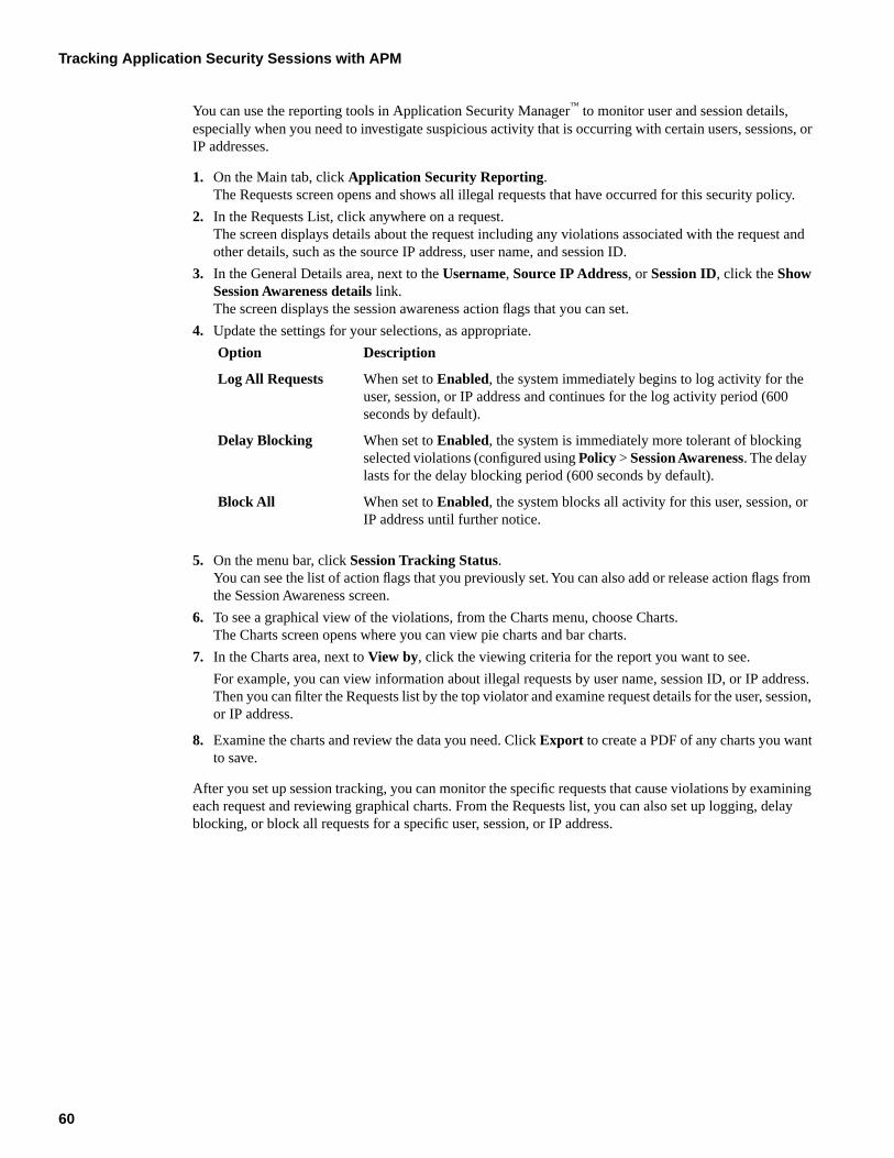
You can use the reporting tools in Application Security Manager™ to monitor user and session details,especially when you need to investigate suspicious activity that is occurring with certain users, sessions, orIP addresses.
1. On the Main tab, click Application Security Reporting.The Requests screen opens and shows all illegal requests that have occurred for this security policy.
2. In the Requests List, click anywhere on a request.The screen displays details about the request including any violations associated with the request andother details, such as the source IP address, user name, and session ID.
3. In the General Details area, next to the Username, Source IP Address, or Session ID, click the ShowSession Awareness details link.The screen displays the session awareness action flags that you can set.
4. Update the settings for your selections, as appropriate.
DescriptionOption
When set to Enabled, the system immediately begins to log activity for theuser, session, or IP address and continues for the log activity period (600seconds by default).
Log All Requests
When set to Enabled, the system is immediately more tolerant of blockingselected violations (configured using Policy > Session Awareness. The delaylasts for the delay blocking period (600 seconds by default).
Delay Blocking
When set to Enabled, the system blocks all activity for this user, session, orIP address until further notice.
Block All
5. On the menu bar, click Session Tracking Status.You can see the list of action flags that you previously set. You can also add or release action flags fromthe Session Awareness screen.
6. To see a graphical view of the violations, from the Charts menu, choose Charts.The Charts screen opens where you can view pie charts and bar charts.
7. In the Charts area, next to View by, click the viewing criteria for the report you want to see.
For example, you can view information about illegal requests by user name, session ID, or IP address.Then you can filter the Requests list by the top violator and examine request details for the user, session,or IP address.
8. Examine the charts and review the data you need. Click Export to create a PDF of any charts you wantto save.
After you set up session tracking, you can monitor the specific requests that cause violations by examiningeach request and reviewing graphical charts. From the Requests list, you can also set up logging, delayblocking, or block all requests for a specific user, session, or IP address.
60
Tracking Application Security Sessions with APM
Chapter
7
Automatically Creating Security Policies for AJAXApplications
Topics:
• Application security for applications that useAJAX
• Overview: Creating a security policy forapplications that use AJAX
• Implementation result
Application security for applications that use AJAX
Application Security Manager™ can protect AJAX applications including those that use JSON or XML fordata transfer between the client and the server. If the AJAX application uses XML for data transfer, thesecurity policy requires that an XML profile be associated with a URL or parameter. If the AJAX applicationuses JSON for data transfer, the security policy requires that a JSON profile be associated with a URL orparameter. If the AJAX application uses HTTP for data transfer, no profile is needed.
You can also set up AJAX blocking response behavior for applications so that if a violation occurs duringAJAX-generated traffic, the system displays a message or redirects the application user to another location.
Overview: Creating a security policy for applications that use AJAX
AJAX (Asynchronous JavaScript and XML) applications make requests to the server and send responsesto the client formatted using XML or JavaScript Object Notation (JSON). You can create a security policyautomatically for applications that use AJAX.
Task Summary
Creating a security policy automatically
Reviewing security policy status
Creating a security policy automatically
Before you can create a security policy, you must perform the minimal system configuration tasks includingdefining a VLAN, a self IP address, and other tasks required according to the needs of your networkingenvironment.
Application Security Manager™ can automatically create a security policy that is tailored to secure yourweb application.
1. On the Main tab, click Application Security > Security Policies.The Active Policies screen opens.
2. Click the Create button.The Deployment wizard opens to the Select Local Traffic Deployment Scenario screen.
3. For the Local Traffic Deployment Scenario setting, specify a virtual server to use for the securitypolicy.
• Select Existing Virtual Server and click Next to use an existing virtual server (as long as it doesnot have an HTTP Class profile associated with it).
• Select New Virtual Server and click Next to create a new virtual server and pool with basicconfiguration settings.
The virtual server represents the web application you want to protect. The system automatically createsan HTTP Class with the same name as the virtual server.
The Configure Local Traffic Settings screen opens.
4. Configure the new or existing virtual server, and click Next.
62
Automatically Creating Security Policies for AJAX Applications
The Select Deployment Scenario screen opens.
5. For Deployment Scenario, select Create a policy automatically and click Next.The Configure Security Policy Properties screen opens.
6. From the Application Language list, select the language encoding of the application, or select Autodetect and let the system detect the language.
Important: You cannot change this setting after you have created the security policy.
7. If the application is not case-sensitive, clear the Security Policy is case sensitive check box. Otherwise,leave it selected.
Important: You cannot change this setting after you have created the security policy.
8. Click Next.The Configure Attack Signatures screen opens.
9. To configure attack signatures, move the systems used by your web application from the AvailableSystems list into the Assigned Systems list.The system adds the attack signatures needed to protect the selected systems.
10. For the Signature Staging setting, verify that the default option Enabled is selected.
Note: Because the Real Traffic Policy Builder® begins building the security policy in Blockingmode, it is a good idea to keep signature staging enabled to make sure that false positives donot occur.
New and updated attack signatures remain in staging for 7 days, and are not enforced (according to thelearn, alarm, and block flags) during that time.
11. Click Next.The Configure Automatic Policy Building screen opens.
12. For Policy Type, select an option to determine the security features to include in the policy.
DescriptionOptions
Creates a security policy enforcing HTTP request protocol compliance, evasiontechniques, allowed file types (including length checks), attack signatures, theviolation Request Length Exceeds Defined Buffer Size, and host names.
Fundamental
Creates a security policy with all the elements of the Fundamental policy type;also checks for global parameters (including length checks), cookies, and allowedmethods to the security policy.
Enhanced
Creates a security policy with all the elements of the Enhanced policy type;also checks for allowed URLs, meta characters on URLs, meta characters on
Comprehensive
parameters, URL parameters (instead of global parameters), and dynamicparameters.
A bulleted list on the screen describes which security features are included in each type.
13. For Rules, move the slider to set the Policy Builder learning speed.
DescriptionOption
Use for a small number of requests from a small number of sessions; for example,useful for web sites with less traffic. However, there is a greater chance of addingfalse entities to the security policy.
Fast
63
BIG-IP® Application Security Manager™: Implementations
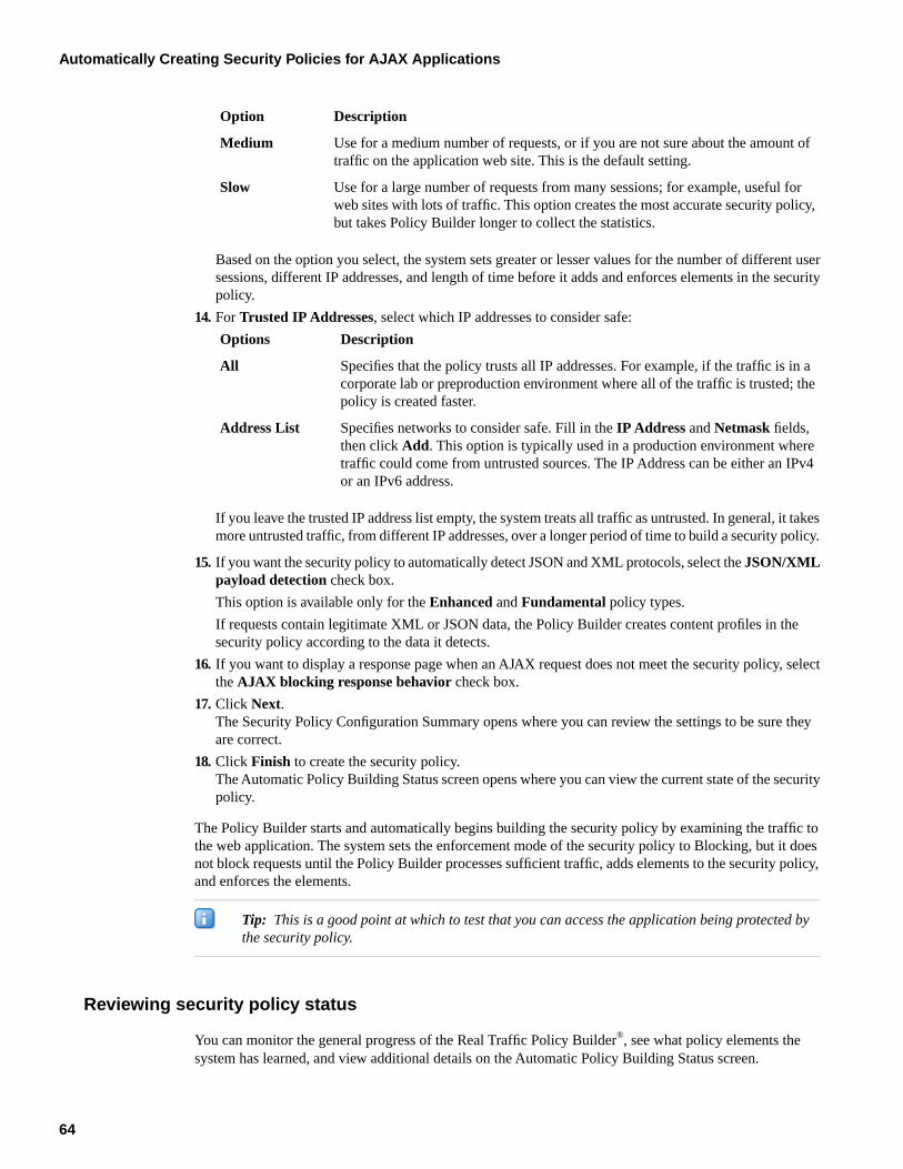
DescriptionOption
Use for a medium number of requests, or if you are not sure about the amount oftraffic on the application web site. This is the default setting.
Medium
Use for a large number of requests from many sessions; for example, useful forweb sites with lots of traffic. This option creates the most accurate security policy,but takes Policy Builder longer to collect the statistics.
Slow
Based on the option you select, the system sets greater or lesser values for the number of different usersessions, different IP addresses, and length of time before it adds and enforces elements in the securitypolicy.
14. For Trusted IP Addresses, select which IP addresses to consider safe:
DescriptionOptions
Specifies that the policy trusts all IP addresses. For example, if the traffic is in acorporate lab or preproduction environment where all of the traffic is trusted; thepolicy is created faster.
All
Specifies networks to consider safe. Fill in the IP Address and Netmask fields,then click Add. This option is typically used in a production environment where
Address List
traffic could come from untrusted sources. The IP Address can be either an IPv4or an IPv6 address.
If you leave the trusted IP address list empty, the system treats all traffic as untrusted. In general, it takesmore untrusted traffic, from different IP addresses, over a longer period of time to build a security policy.
15. If you want the security policy to automatically detect JSON and XML protocols, select the JSON/XMLpayload detection check box.
This option is available only for the Enhanced and Fundamental policy types.
If requests contain legitimate XML or JSON data, the Policy Builder creates content profiles in thesecurity policy according to the data it detects.
16. If you want to display a response page when an AJAX request does not meet the security policy, selectthe AJAX blocking response behavior check box.
17. Click Next.The Security Policy Configuration Summary opens where you can review the settings to be sure theyare correct.
18. Click Finish to create the security policy.The Automatic Policy Building Status screen opens where you can view the current state of the securitypolicy.
The Policy Builder starts and automatically begins building the security policy by examining the traffic tothe web application. The system sets the enforcement mode of the security policy to Blocking, but it doesnot block requests until the Policy Builder processes sufficient traffic, adds elements to the security policy,and enforces the elements.
Tip: This is a good point at which to test that you can access the application being protected bythe security policy.
Reviewing security policy status
You can monitor the general progress of the Real Traffic Policy Builder®, see what policy elements thesystem has learned, and view additional details on the Automatic Policy Building Status screen.
64
Automatically Creating Security Policies for AJAX Applications
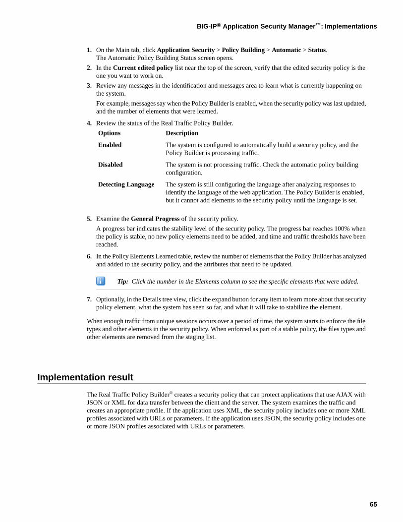
1. On the Main tab, click Application Security > Policy Building > Automatic > Status.The Automatic Policy Building Status screen opens.
2. In the Current edited policy list near the top of the screen, verify that the edited security policy is theone you want to work on.
3. Review any messages in the identification and messages area to learn what is currently happening onthe system.
For example, messages say when the Policy Builder is enabled, when the security policy was last updated,and the number of elements that were learned.
4. Review the status of the Real Traffic Policy Builder.
DescriptionOptions
The system is configured to automatically build a security policy, and thePolicy Builder is processing traffic.
Enabled
The system is not processing traffic. Check the automatic policy buildingconfiguration.
Disabled
The system is still configuring the language after analyzing responses toidentify the language of the web application. The Policy Builder is enabled,but it cannot add elements to the security policy until the language is set.
Detecting Language
5. Examine the General Progress of the security policy.
A progress bar indicates the stability level of the security policy. The progress bar reaches 100% whenthe policy is stable, no new policy elements need to be added, and time and traffic thresholds have beenreached.
6. In the Policy Elements Learned table, review the number of elements that the Policy Builder has analyzedand added to the security policy, and the attributes that need to be updated.
Tip: Click the number in the Elements column to see the specific elements that were added.
7. Optionally, in the Details tree view, click the expand button for any item to learn more about that securitypolicy element, what the system has seen so far, and what it will take to stabilize the element.
When enough traffic from unique sessions occurs over a period of time, the system starts to enforce the filetypes and other elements in the security policy. When enforced as part of a stable policy, the files types andother elements are removed from the staging list.
Implementation result
The Real Traffic Policy Builder® creates a security policy that can protect applications that use AJAX withJSON or XML for data transfer between the client and the server. The system examines the traffic andcreates an appropriate profile. If the application uses XML, the security policy includes one or more XMLprofiles associated with URLs or parameters. If the application uses JSON, the security policy includes oneor more JSON profiles associated with URLs or parameters.
65
BIG-IP® Application Security Manager™: Implementations

66
Automatically Creating Security Policies for AJAX Applications
Chapter
8
Adding JSON Support to an Existing Security Policy
Topics:
• Overview: Adding JSON support to existingsecurity policies
• Implementation result
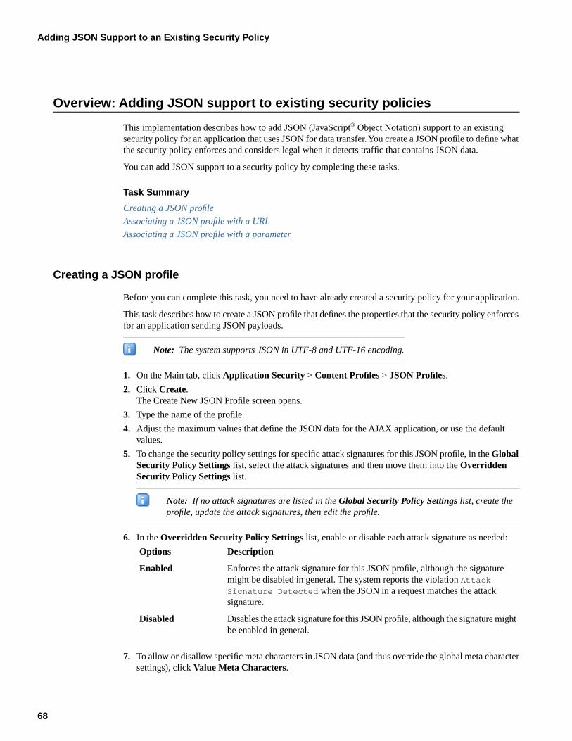
Overview: Adding JSON support to existing security policies
This implementation describes how to add JSON (JavaScript® Object Notation) support to an existingsecurity policy for an application that uses JSON for data transfer. You create a JSON profile to define whatthe security policy enforces and considers legal when it detects traffic that contains JSON data.
You can add JSON support to a security policy by completing these tasks.
Task Summary
Creating a JSON profile
Associating a JSON profile with a URL
Associating a JSON profile with a parameter
Creating a JSON profile
Before you can complete this task, you need to have already created a security policy for your application.
This task describes how to create a JSON profile that defines the properties that the security policy enforcesfor an application sending JSON payloads.
Note: The system supports JSON in UTF-8 and UTF-16 encoding.
1. On the Main tab, click Application Security > Content Profiles > JSON Profiles.
2. Click Create.The Create New JSON Profile screen opens.
3. Type the name of the profile.
4. Adjust the maximum values that define the JSON data for the AJAX application, or use the defaultvalues.
5. To change the security policy settings for specific attack signatures for this JSON profile, in the GlobalSecurity Policy Settings list, select the attack signatures and then move them into the OverriddenSecurity Policy Settings list.
Note: If no attack signatures are listed in the Global Security Policy Settings list, create theprofile, update the attack signatures, then edit the profile.
6. In the Overridden Security Policy Settings list, enable or disable each attack signature as needed:
DescriptionOptions
Enforces the attack signature for this JSON profile, although the signaturemight be disabled in general. The system reports the violation Attack
Enabled
Signature Detected when the JSON in a request matches the attacksignature.
Disables the attack signature for this JSON profile, although the signature mightbe enabled in general.
Disabled
7. To allow or disallow specific meta characters in JSON data (and thus override the global meta charactersettings), click Value Meta Characters.
68
Adding JSON Support to an Existing Security Policy
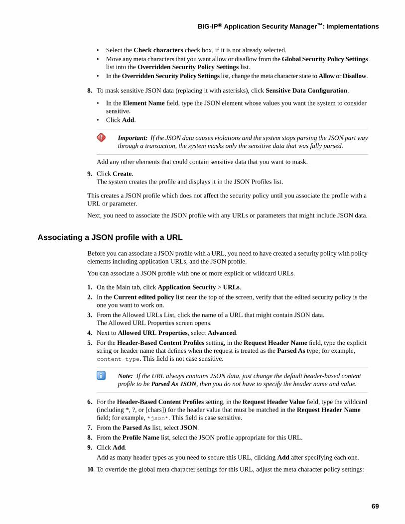
• Select the Check characters check box, if it is not already selected.• Move any meta characters that you want allow or disallow from the Global Security Policy Settings
list into the Overridden Security Policy Settings list.• In the Overridden Security Policy Settings list, change the meta character state to Allow or Disallow.
8. To mask sensitive JSON data (replacing it with asterisks), click Sensitive Data Configuration.
• In the Element Name field, type the JSON element whose values you want the system to considersensitive.
• Click Add.
Important: If the JSON data causes violations and the system stops parsing the JSON part waythrough a transaction, the system masks only the sensitive data that was fully parsed.
Add any other elements that could contain sensitive data that you want to mask.
9. Click Create.The system creates the profile and displays it in the JSON Profiles list.
This creates a JSON profile which does not affect the security policy until you associate the profile with aURL or parameter.
Next, you need to associate the JSON profile with any URLs or parameters that might include JSON data.
Associating a JSON profile with a URL
Before you can associate a JSON profile with a URL, you need to have created a security policy with policyelements including application URLs, and the JSON profile.
You can associate a JSON profile with one or more explicit or wildcard URLs.
1. On the Main tab, click Application Security > URLs.
2. In the Current edited policy list near the top of the screen, verify that the edited security policy is theone you want to work on.
3. From the Allowed URLs List, click the name of a URL that might contain JSON data.The Allowed URL Properties screen opens.
4. Next to Allowed URL Properties, select Advanced.
5. For the Header-Based Content Profiles setting, in the Request Header Name field, type the explicitstring or header name that defines when the request is treated as the Parsed As type; for example,content-type. This field is not case sensitive.
Note: If the URL always contains JSON data, just change the default header-based contentprofile to be Parsed As JSON, then you do not have to specify the header name and value.
6. For the Header-Based Content Profiles setting, in the Request Header Value field, type the wildcard(including *, ?, or [chars]) for the header value that must be matched in the Request Header Namefield; for example, *json*. This field is case sensitive.
7. From the Parsed As list, select JSON.
8. From the Profile Name list, select the JSON profile appropriate for this URL.
9. Click Add.
Add as many header types as you need to secure this URL, clicking Add after specifying each one.
10. To override the global meta character settings for this URL, adjust the meta character policy settings:
69
BIG-IP® Application Security Manager™: Implementations
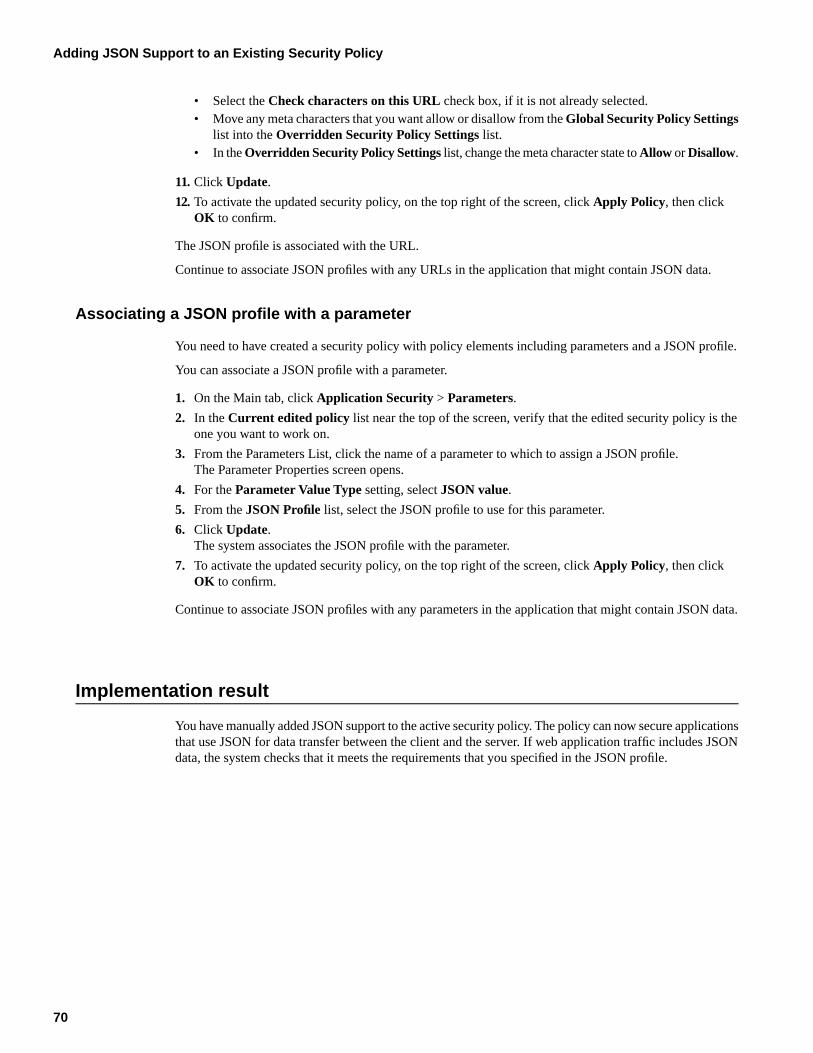
• Select the Check characters on this URL check box, if it is not already selected.• Move any meta characters that you want allow or disallow from the Global Security Policy Settings
list into the Overridden Security Policy Settings list.• In the Overridden Security Policy Settings list, change the meta character state to Allow or Disallow.
11. Click Update.
12. To activate the updated security policy, on the top right of the screen, click Apply Policy, then clickOK to confirm.
The JSON profile is associated with the URL.
Continue to associate JSON profiles with any URLs in the application that might contain JSON data.
Associating a JSON profile with a parameter
You need to have created a security policy with policy elements including parameters and a JSON profile.
You can associate a JSON profile with a parameter.
1. On the Main tab, click Application Security > Parameters.
2. In the Current edited policy list near the top of the screen, verify that the edited security policy is theone you want to work on.
3. From the Parameters List, click the name of a parameter to which to assign a JSON profile.The Parameter Properties screen opens.
4. For the Parameter Value Type setting, select JSON value.
5. From the JSON Profile list, select the JSON profile to use for this parameter.
6. Click Update.The system associates the JSON profile with the parameter.
7. To activate the updated security policy, on the top right of the screen, click Apply Policy, then clickOK to confirm.
Continue to associate JSON profiles with any parameters in the application that might contain JSON data.
Implementation result
You have manually added JSON support to the active security policy. The policy can now secure applicationsthat use JSON for data transfer between the client and the server. If web application traffic includes JSONdata, the system checks that it meets the requirements that you specified in the JSON profile.
70
Adding JSON Support to an Existing Security Policy
Chapter
9
Adding AJAX Blocking Response Behavior to a SecurityPolicy
Topics:
• Overview: Adding AJAX blocking and loginresponse behavior
• Configuring the blocking response for AJAXapplications
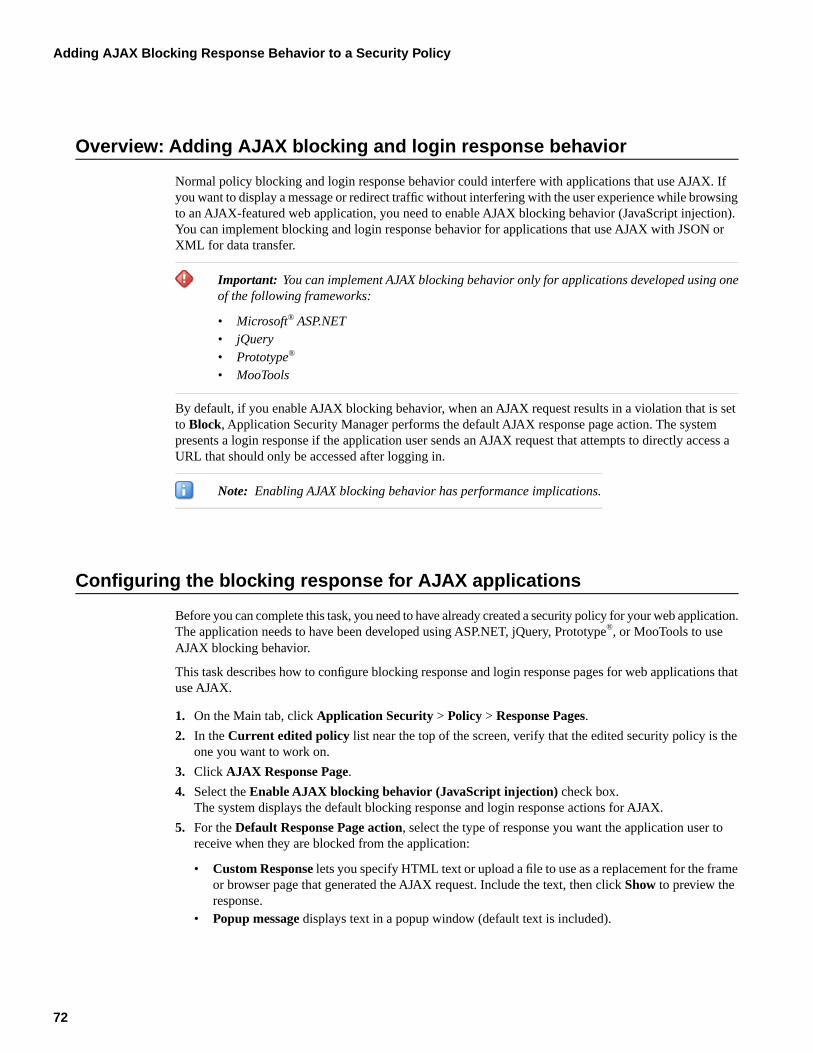
Overview: Adding AJAX blocking and login response behavior
Normal policy blocking and login response behavior could interfere with applications that use AJAX. Ifyou want to display a message or redirect traffic without interfering with the user experience while browsingto an AJAX-featured web application, you need to enable AJAX blocking behavior (JavaScript injection).You can implement blocking and login response behavior for applications that use AJAX with JSON orXML for data transfer.
Important: You can implement AJAX blocking behavior only for applications developed using oneof the following frameworks:
• Microsoft® ASP.NET• jQuery• Prototype®
• MooTools
By default, if you enable AJAX blocking behavior, when an AJAX request results in a violation that is setto Block, Application Security Manager performs the default AJAX response page action. The systempresents a login response if the application user sends an AJAX request that attempts to directly access aURL that should only be accessed after logging in.
Note: Enabling AJAX blocking behavior has performance implications.
Configuring the blocking response for AJAX applications
Before you can complete this task, you need to have already created a security policy for your web application.The application needs to have been developed using ASP.NET, jQuery, Prototype®, or MooTools to useAJAX blocking behavior.
This task describes how to configure blocking response and login response pages for web applications thatuse AJAX.
1. On the Main tab, click Application Security > Policy > Response Pages.
2. In the Current edited policy list near the top of the screen, verify that the edited security policy is theone you want to work on.
3. Click AJAX Response Page.
4. Select the Enable AJAX blocking behavior (JavaScript injection) check box.The system displays the default blocking response and login response actions for AJAX.
5. For the Default Response Page action, select the type of response you want the application user toreceive when they are blocked from the application:
• Custom Response lets you specify HTML text or upload a file to use as a replacement for the frameor browser page that generated the AJAX request. Include the text, then click Show to preview theresponse.
• Popup message displays text in a popup window (default text is included).
72
Adding AJAX Blocking Response Behavior to a Security Policy
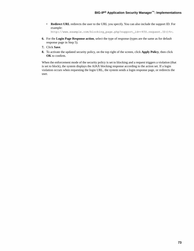
• Redirect URL redirects the user to the URL you specify. You can also include the support ID. Forexample:http://www.example.com/blocking_page.php?support_id=<%TS.request.ID()%>.
6. For the Login Page Response action, select the type of response (types are the same as for defaultresponse page in Step 5).
7. Click Save.
8. To activate the updated security policy, on the top right of the screen, click Apply Policy, then clickOK to confirm.
When the enforcement mode of the security policy is set to blocking and a request triggers a violation (thatis set to block), the system displays the AJAX blocking response according to the action set. If a loginviolation occurs when requesting the login URL, the system sends a login response page, or redirects theuser.
73
BIG-IP® Application Security Manager™: Implementations

74
Adding AJAX Blocking Response Behavior to a Security Policy
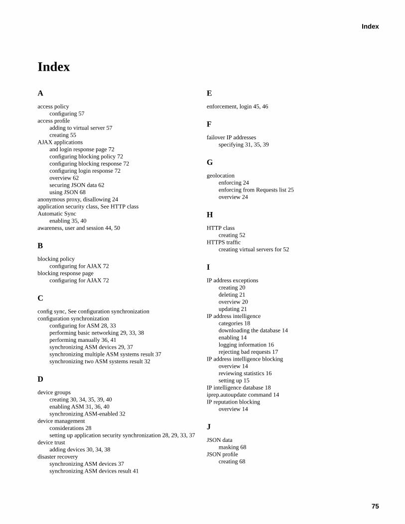
Index
A
access policyconfiguring 57
access profileadding to virtual server 57creating 55
AJAX applicationsand login response page 72configuring blocking policy 72configuring blocking response 72configuring login response 72overview 62securing JSON data 62using JSON 68
anonymous proxy, disallowing 24application security class, See HTTP classAutomatic Sync
enabling 35, 40awareness, user and session 44, 50
B
blocking policyconfiguring for AJAX 72
blocking response pageconfiguring for AJAX 72
C
config sync, See configuration synchronizationconfiguration synchronization
configuring for ASM 28, 33performing basic networking 29, 33, 38performing manually 36, 41synchronizing ASM devices 29, 37synchronizing multiple ASM systems result 37synchronizing two ASM systems result 32
D
device groupscreating 30, 34, 35, 39, 40enabling ASM 31, 36, 40synchronizing ASM-enabled 32
device managementconsiderations 28setting up application security synchronization 28, 29, 33, 37
device trustadding devices 30, 34, 38
disaster recoverysynchronizing ASM devices 37synchronizing ASM devices result 41
E
enforcement, login 45, 46
F
failover IP addressesspecifying 31, 35, 39
G
geolocationenforcing 24enforcing from Requests list 25overview 24
H
HTTP classcreating 52
HTTPS trafficcreating virtual servers for 52
I
IP address exceptionscreating 20deleting 21overview 20updating 21
IP address intelligencecategories 18downloading the database 14enabling 14logging information 16rejecting bad requests 17
IP address intelligence blockingoverview 14reviewing statistics 16setting up 15
IP intelligence database 18iprep.autoupdate command 14IP reputation blocking
overview 14
J
JSON datamasking 68
JSON profilecreating 68
75
Index

L
local traffic poolscreating 51
local trust domainand device groups 30, 34, 35, 40
local trust domainsadding devices 30, 34, 38and device groups 39
login enforcement 45login pages
creating 44enforcing 45
login response pageconfiguring for AJAX 72
log IP address intelligence information 16
M
malicious IP address 15
N
network failoverconfiguring 30, 34, 39
P
parametersassociating with JSON profiles 70
policy, See security policy.pools
creating local traffic 51profiles
associating parameters with JSON 70associating URLs with JSON 69creating JSON 68
S
security policycreating automatically 53, 62reviewing status 64synchronizing ASM 32
security policy synchronizationconfiguring 28, 29, 33, 37
self IP addressesand VLANs 51creating 51
sensitive datamasking JSON 68
session awarenessenabling 46enabling with APM 58
sessions, monitoring 47, 59session tracking
enabling 46enabling with APM 58overview 44, 50prerequisites 50
Sync-Failover device groupscreating 30, 34, 39
synchronizationconfiguring for ASM 29, 37configuring multiple ASM systems result 37configuring two ASM systems result 32performing manually 36, 41
Sync-Only device groupscreating 35, 40
T
trustadding devices 30, 34, 38
U
URLsassociating with JSON profiles 69
user awarenessoverview 44, 50
user information, monitoring 47, 59
V
virtual serverscreating for HTTPS traffic 52
VLANsand self IP addresses 51creating 50
76
Index


![PHYSICAL SECURITY & ENVIRONMENTAL SECURITY · Physical Security & Environmental Security Policy and Procedures Title [company name] Physical Security & Environmental Security Policy](https://img.pdfslide.net/doc/110x75/5b5559c77f8b9ac5358b71e4/physical-security-environmental-security-physical-security-environmental.jpg)