Embed Size (px)
Citation preview
BLITZORTUNG SYSTEM RED ASSEMBLY
Blitzortung-RED-Assembly-Instructions.docx Pg: 1 of 29 Revised: 10/3/2013 9:02:00 PM
Blitzortung System RED Kit
Step-by-Step Assembly
Instructions
Written for the following PCB Versions ONLY
Amplifier
PCB Ver. 3 * 7/2013
Controller
PCB Ver. 3b * 8/2013
DISCLAIMER: This document is a personal, private endeavor. It is not being written with the approval
or sanction of the Blitzortung group. Use of this document is at your own risk.
BLITZORTUNG SYSTEM RED ASSEMBLY
Blitzortung-RED-Assembly-Instructions.docx Pg: 2 of 29 Revised: 10/3/2013 9:02:00 PM
This document is a work in progress. It is being developed as I build my own Blitzortung
System RED Lightning Detector. As I build my system, I will add to this document so
everyone will be able to follow my way of building my detector. This is my first attempt
at soldering SMDs. I have had over 50 years of electronics experience in computers and
communications systems and have soldered literally thousands of standard printed
circuit board connections but SMD devices are new to my repertoire. I have attempted
to collect some of the experiences of others System RED builders as listed in the several
Blitzortung forums. I cannot claim any credit for any of the myriad of suggestions, tips
and hints. I am only trying to bring many of those ideas into a single document with the
hope that many more folks will take interest in the Blitzortung project and build their
own systems. Please feel free to suggest changes, corrections or better ways of making
this a more usable document for everyone.
There have been numerous requests on the forums for a “step by step” assembly
instruction manual. Hopefully, this document will begin to fill some of those requests.
Thanks for taking the time to look this document over.
Don McRoberts – W3DRM
Minden, Nevada – USA
NOTE: These instructions have not been verified for accuracy. That will
happen as I finalize the document at a later time. Use this with caution.
No guarantees are made. Use it at your own risk…
BLITZORTUNG SYSTEM RED ASSEMBLY
Blitzortung-RED-Assembly-Instructions.docx Pg: 3 of 29 Revised: 10/3/2013 9:02:00 PM
These instructions have been put together to assist you in getting started with the assembly of your
Blitzortung System RED Lightning Detector.
The first step is to provide you with a listing of suggested tools and supplies you will need during the
inventory and assembly phases of the building project. Once you have obtained the recommended
tools and supplies, we will begin the process of inventorying and then assembling the kit.
The inventory kit will ensure you have a complete kit and are ready to begin with the assembly phase.
NOTE: As a precautionary measure and before you open and touch any of the components, read the
following three paragraphs.
While there have been no reports of System RED components being damaged by electrostatic
discharge (ESD) during their handling and installation, it would be wise to take this into account,
especially if you live in an area that has very low humidity levels.
Due to the potential of damaging the sensitive components in your kit with an electrostatic discharge
(ESD) it is recommended that you take precautions to minimize the ESD possibilities. This can be done
by ensuring that you and all of the equipment and components are at the same potential (grounded)
through the use of an anti-static mat and an anti-static wristband. Both of these items are attached to
a common ground.
If you do not have an anti-static mat or wristband, you can find them on-line at Radio Shack (part
number: 276-2370 - http://www.radioshack.com/product/index.jsp?productId=2102871) or other
electronics parts outlet. Just Google “anti-static mat” and you will find many resources. Amazon and
eBay are also resources.
A complete list of components and a checklist is available on the Internet to help you inventory your
kit. It can be found by going to the WXFORUM.NET web-forum at the following URL:
http://www.wxforum.net/index.php?topic=20037.0
The steps outlined below will help you to complete your inventory, assembly and testing of your new
Blitzortung System RED Lightning Detection System. This document is laid-out in the following format:
Section I – Recommended Tools and Accessories
Section II – Inventory your Kit
Section III – Assembly of your RED Kit
a) Assemble Amplifier PCB components
b) Assemble Controller PCB components
Section IV – Testing of your completed Kit
Section V – Troubleshooting
Section VI – Reference Information
BLITZORTUNG SYSTEM RED ASSEMBLY
Blitzortung-RED-Assembly-Instructions.docx Pg: 4 of 29 Revised: 10/3/2013 9:02:00 PM
SECTION I – RECOMMENDED TOOLS AND ACCESSORIES
a) Anti-static Mat & Wristband
b) Digital Multimeter
c) Soldering Iron - Temperature Controlled w/Fine Tip
d) Solder
a. Radio Shack 0.015” diameter, 62/36/2, Silver-bearing Solder. Part Number: 64-035, or
equivalent http://www.radioshack.com/product/index.jsp?productId=2062725
NOTE: Lead-free solder is NOT recommended.
e) Desoldering Braid or Solder Pump
a. Desoldering Braid - Radio Shack Part Number: 64-2090
http://www.radioshack.com/product/index.jsp?productId=2062744&locale=en_US
b. Solder Pump – Radio Shack Part Number: 64-210
http://www.radioshack.com/product/index.jsp?productId=17241906
f) Liquid Solder Flux (optional – helps the solder to flow better. Used only on SMDs)
a. Radio Shack Part Number: 55047964
http://www.radioshack.com/product/index.jsp?productId=12580192
g) Small diagonal cutters
a. Radio Shack Part Number: 64-024
http://www.radioshack.com/product/index.jsp?productId=3932532
h) High Intensity Lamp
i) Magnifying Glass or Loop (10X to 30X)
a. A lighted version of these would be helpful too
j) Painter’s Tape or Masking Tape to mark components during the inventory phase.
k) Sharpie Marker – Ultra Fine
l) Oscilloscope – optional but can be handy during troubleshooting.
m) Wooden Chop Sticks – used to position and hold the ICs in place during soldering.
BLITZORTUNG SYSTEM RED ASSEMBLY
Blitzortung-RED-Assembly-Instructions.docx Pg: 5 of 29 Revised: 10/3/2013 9:02:00 PM
SECTION II – INVENTORY YOUR KIT
The Blitzortung System RED Kit will arrive in a box that contains several plastic bags. The Amplifier and
Controller parts are mixed together so it is a good idea to begin separating the parts as you do your
inventory.
a) Start the inventory with the resistors. Using the component check-list
(http://carsonvalleyweather.com/blitzortung/docs/System-RED-Kit-Parts-Amplifier-12-v3.pdf),
identify and mark each resistor. It is suggested that you use a digital multi-meter (DMM) to
ensure the correct value of each resistor being identified. The resistors used are very small and
the color bands are difficult to see.
b) Inventory the Capacitors next. On some of these you will not see any value stamped, only
a number. The inventory check-list shows those items with their identifying numbers. The
Blitzortung System RED Manual
(http://carsonvalleyweather.com/blitzortung/docs/TOA_Blitzortung_RED-2013-08-23.pdf) also
has a parts listing along with a few color images of the individual resistors and capacitors to
help you identify the various components.
c) Inventory the remaining IC’s, Transistors and other electronic components.
d) You will also find numerous other non-electronic parts in the bags. Currently there is no
list of these items but they can easily be identified by viewing the images in the above
mentioned System RED manual. I would suggest that you simply lay your Amplifier and
Controller boards down with the writing facing up and the insert each non-electronic
component in its place. Do not force any item. If you have problems inserting the part, check
the pin alignment to ensure the pins are not bent.
a. Please note, there are two single row 10-pin (1 x 10) connectors that are used on the
Controller board for the LCD display. You will have to snip or pinch-off the last pin on
each of these connectors or they won’t fit on the Controller board. See the instructions
in the System RED Manual for details (Pg. 22, Item 2, fourth bullet) – see link to the RED
manual above. These items will be trimmed during the installation procedure.
e) Once you have the items separated, put them in a baggy or some container labeled as
“Amplifier” or “Controller” components. This will help when you begin assembling the PCBs.
BLITZORTUNG SYSTEM RED ASSEMBLY
Blitzortung-RED-Assembly-Instructions.docx Pg: 6 of 29 Revised: 10/3/2013 9:02:00 PM
SECTION III – ASSEMBLY OF YOUR RED KIT
a) Assembly Sequence – Amplifier PCB
Check-off each component as you complete it.
a. Surface Mount Devices (SMDs). We’ll start with these items so we have plenty of room
on the PCB to work. If you are not familiar with soldering of surface mount devices,
there are many good videos available on YouTube. Just search for “surface mount
soldering tutorial”. A good tutorial I have found that covers the basics for various types
of SMD devices is www.youtube.com/watch?v=3NN7UGWYmBY. There are many others
too.
IC2 – Dual op-amp, MCP6292. The dot on each IC must align with the white
dot on the Amplifier PCB. Solder one of the corner pins first to hold the IC in
place. Once it is aligned correctly so that all pins are on their corresponding pads,
solder the remaining pins.
IC6 –Dual op-amp, MCP6292. Follow the instructions as described for IC2
above.
IC4 – Output driver amplifier, LMH6642. Follow the instructions as
described for IC2 above.
IC8 – Output driver amplifier, LMH6642. Follow the instructions as
described for IC2 above.
Congratulations! You have completed the most difficult part of assembling the components on
the Amplifier board.
We will now begin inserting and soldering the smaller components in their respective positions
on the Amplifier board.
BLITZORTUNG SYSTEM RED ASSEMBLY
Blitzortung-RED-Assembly-Instructions.docx Pg: 7 of 29 Revised: 10/3/2013 9:02:00 PM
b. Diodes – 1N4148
The cathode (-) of the diode is marked with a black or white ring on the body of the
diode itself. This side is marked white on the PCB along with the component number ie
(D1, D2, etc). Bend the leads on each diode by holding each lead next to the glass body
with a pair of needle-nose pliers. This will eliminate stressing the diode which may
possibly crack it. Insert each diode all the way in until it touches the PCB. Slightly spread
the leads on the back-side of the PCB so the diode does not fall-out. Do not solder until
all four diodes have been inserted.
D1 – 1N4148 diode. Prepare and insert the diode into the designated holes
on the PCB.
D2 – 1N4148 diode. Follow the instructions as described above.
D3 – 1N4148 diode. Follow the instructions as described above.
D4 – 1N4148 diode. Follow the instructions as described above.
Solder all four diodes just inserted.
Clip the leads on the backside of the PCB for all four diodes.
BLITZORTUNG SYSTEM RED ASSEMBLY
Blitzortung-RED-Assembly-Instructions.docx Pg: 8 of 29 Revised: 10/3/2013 9:02:00 PM
c. Resistor Installation
We will now begin inserting and soldering the resistors on the Amplifier board.
We’ll start on the left-side of the PCB with it oriented so the antenna input section is on the
left. R1 will be in the upper left-side of the PCB. The resistors can be inserted in any
direction. I suggest inserting only a few at a time so it is easier to solder and clip the leads as
you go. Bend the leads as you did with the diodes earlier.
R1 2.2KΩ Prepare and insert the resistor into the designated holes
on the PCB.
R2 10KΩ Follow the instructions as described above.
R3 100KΩ Follow the instructions as described above.
R16 2.2KΩ Follow the instructions as described above.
R17 10KΩ Follow the instructions as described above.
R18 100KΩ Follow the instructions as described above.
R5 22KΩ Follow the instructions as described above.
R20 22KΩ Follow the instructions as described above.
R4 10KΩ Follow the instructions as described above.
R7 22KΩ Follow the instructions as described above.
R9 2.2KΩ Follow the instructions as described above.
R19 10KΩ Follow the instructions as described above.
R22 22KΩ Follow the instructions as described above.
R24 2.2KΩ Follow the instructions as described above.
R8 6.8KΩ Follow the instructions as described above.
R6 68KΩ Follow the instructions as described above.
BLITZORTUNG SYSTEM RED ASSEMBLY
Blitzortung-RED-Assembly-Instructions.docx Pg: 9 of 29 Revised: 10/3/2013 9:02:00 PM
R23 6.8KΩ Follow the instructions as described above.
R21 68KΩ Follow the instructions as described above.
R10 1KΩ Follow the instructions as described above.
R25 1KΩ Follow the instructions as described above.
R11 1KΩ Follow the instructions as described above.
R26 1KΩ Follow the instructions as described above.
R31 10KΩ Follow the instructions as described above.
R12 22KΩ Follow the instructions as described above.
R27 22KΩ Follow the instructions as described above.
R32 2.2KΩ Follow the instructions as described above.
R33 2.2KΩ Follow the instructions as described above.
R13 100KΩ Follow the instructions as described above.
R14 10KΩ Follow the instructions as described above.
R28 100KΩ Follow the instructions as described above.
R29 10KΩ Follow the instructions as described above.
R15 47Ω Follow the instructions as described above.
R30 47Ω Follow the instructions as described above.
R34 330Ω Follow the instructions as described above.
R35 330Ω Follow the instructions as described above.
Go back over all of the resistors to be certain they have been soldered and have
their excess leads clipped from the back of the PCB.
BLITZORTUNG SYSTEM RED ASSEMBLY
Blitzortung-RED-Assembly-Instructions.docx Pg: 10 of 29 Revised: 10/3/2013 9:02:00 PM
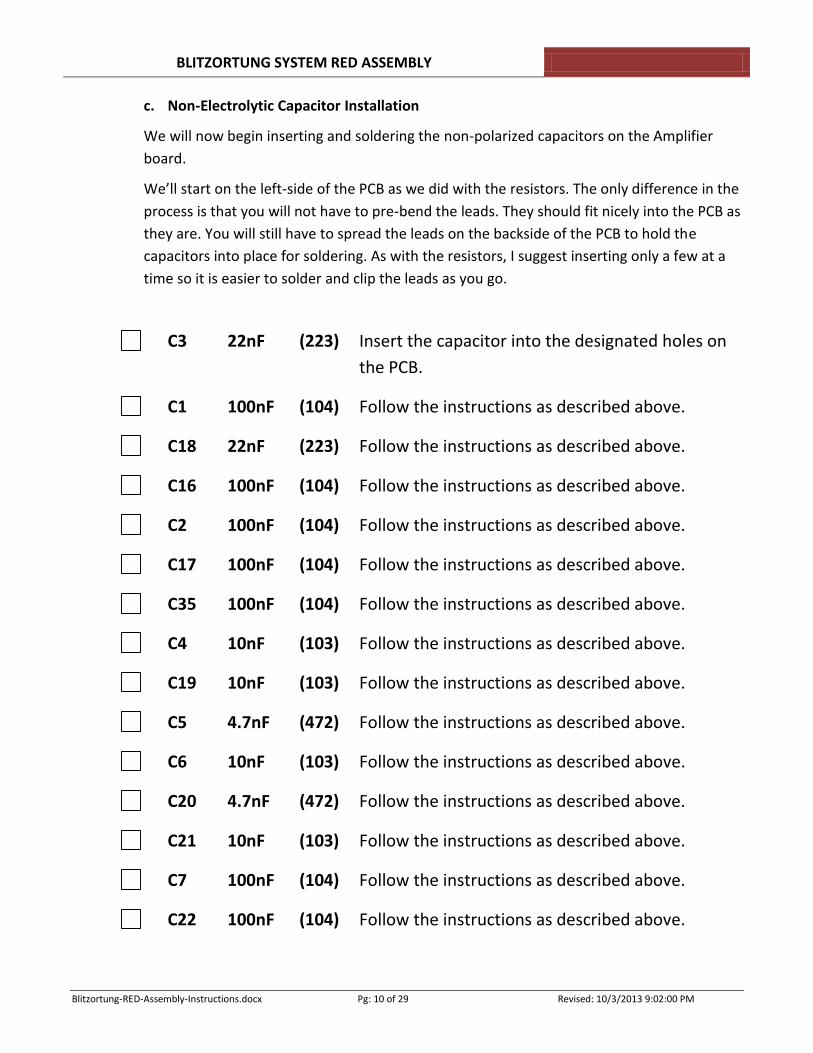
c. Non-Electrolytic Capacitor Installation
We will now begin inserting and soldering the non-polarized capacitors on the Amplifier
board.
We’ll start on the left-side of the PCB as we did with the resistors. The only difference in the
process is that you will not have to pre-bend the leads. They should fit nicely into the PCB as
they are. You will still have to spread the leads on the backside of the PCB to hold the
capacitors into place for soldering. As with the resistors, I suggest inserting only a few at a
time so it is easier to solder and clip the leads as you go.
C3 22nF (223) Insert the capacitor into the designated holes on
the PCB.
C1 100nF (104) Follow the instructions as described above.
C18 22nF (223) Follow the instructions as described above.
C16 100nF (104) Follow the instructions as described above.
C2 100nF (104) Follow the instructions as described above.
C17 100nF (104) Follow the instructions as described above.
C35 100nF (104) Follow the instructions as described above.
C4 10nF (103) Follow the instructions as described above.
C19 10nF (103) Follow the instructions as described above.
C5 4.7nF (472) Follow the instructions as described above.
C6 10nF (103) Follow the instructions as described above.
C20 4.7nF (472) Follow the instructions as described above.
C21 10nF (103) Follow the instructions as described above.
C7 100nF (104) Follow the instructions as described above.
C22 100nF (104) Follow the instructions as described above.
BLITZORTUNG SYSTEM RED ASSEMBLY
Blitzortung-RED-Assembly-Instructions.docx Pg: 11 of 29 Revised: 10/3/2013 9:02:00 PM
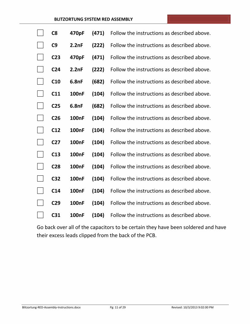
C8 470pF (471) Follow the instructions as described above.
C9 2.2nF (222) Follow the instructions as described above.
C23 470pF (471) Follow the instructions as described above.
C24 2.2nF (222) Follow the instructions as described above.
C10 6.8nF (682) Follow the instructions as described above.
C11 100nF (104) Follow the instructions as described above.
C25 6.8nF (682) Follow the instructions as described above.
C26 100nF (104) Follow the instructions as described above.
C12 100nF (104) Follow the instructions as described above.
C27 100nF (104) Follow the instructions as described above.
C13 100nF (104) Follow the instructions as described above.
C28 100nF (104) Follow the instructions as described above.
C32 100nF (104) Follow the instructions as described above.
C14 100nF (104) Follow the instructions as described above.
C29 100nF (104) Follow the instructions as described above.
C31 100nF (104) Follow the instructions as described above.
Go back over all of the capacitors to be certain they have been soldered and have
their excess leads clipped from the back of the PCB.
BLITZORTUNG SYSTEM RED ASSEMBLY
Blitzortung-RED-Assembly-Instructions.docx Pg: 12 of 29 Revised: 10/3/2013 9:02:00 PM
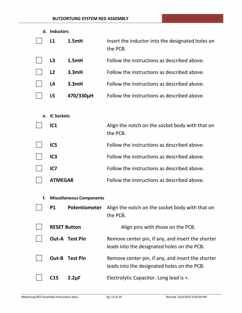
d. Inductors
L1 1.5mH Insert the inductor into the designated holes on
the PCB.
L3 1.5mH Follow the instructions as described above.
L2 3.3mH Follow the instructions as described above.
L4 3.3mH Follow the instructions as described above.
L5 470/330μH Follow the instructions as described above.
e. IC Sockets
IC1 Align the notch on the socket body with that on
the PCB.
IC5 Follow the instructions as described above.
IC3 Follow the instructions as described above.
IC7 Follow the instructions as described above.
ATMEGA8 Follow the instructions as described above.
f. Miscellaneous Components
P1 Potentiometer Align the notch on the socket body with that on
the PCB.
RESET Button Align pins with those on the PCB.
Out-A Test Pin Remove center pin, if any, and insert the shorter
leads into the designated holes on the PCB.
Out-B Test Pin Remove center pin, if any, and insert the shorter
leads into the designated holes on the PCB.
C15 2.2μF Electrolytic Capacitor. Long lead is +.
BLITZORTUNG SYSTEM RED ASSEMBLY
Blitzortung-RED-Assembly-Instructions.docx Pg: 13 of 29 Revised: 10/3/2013 9:02:00 PM
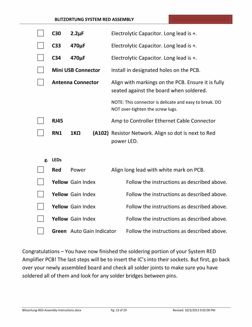
C30 2.2μF Electrolytic Capacitor. Long lead is +.
C33 470μF Electrolytic Capacitor. Long lead is +.
C34 470μF Electrolytic Capacitor. Long lead is +.
Mini USB Connector Install in designated holes on the PCB.
Antenna Connector Align with markings on the PCB. Ensure it is fully
seated against the board when soldered.
NOTE: This connector is delicate and easy to break. DO
NOT over-tighten the screw lugs.
RJ45 Amp to Controller Ethernet Cable Connector
RN1 1KΩ (A102) Resistor Network. Align so dot is next to Red
power LED.
g. LEDs
Red Power Align long lead with white mark on PCB.
Yellow Gain Index Follow the instructions as described above.
Yellow Gain Index Follow the instructions as described above.
Yellow Gain Index Follow the instructions as described above.
Yellow Gain Index Follow the instructions as described above.
Green Auto Gain Indicator Follow the instructions as described above.
Congratulations – You have now finished the soldering portion of your System RED
Amplifier PCB! The last steps will be to insert the IC’s into their sockets. But first, go back
over your newly assembled board and check all solder joints to make sure you have
soldered all of them and look for any solder bridges between pins.
BLITZORTUNG SYSTEM RED ASSEMBLY
Blitzortung-RED-Assembly-Instructions.docx Pg: 14 of 29 Revised: 10/3/2013 9:02:00 PM
We will now insert the IC’s into their sockets.
NOTE: Ensure all pins on the IC’s are straight and not bent. You will not be able to insert
them if any of the pins are not lined-up with the socket.
IC1 MCP6S91 DIP8 Insert the IC into the designated socket.
IC5 MCP6S91 DIP8 Follow the instructions as described above.
IC3 MCP6S91 DIP8 Follow the instructions as described above.
IC7 MCP6S91 DIP8 Follow the instructions as described above.
Microprocessor Controller
ATMEGA8 Insert the IC into the designated socket.
You have now completed the assembly of the Amplifier PCB. We will now perform a
short test to see if things look okay.
Plug-in the 5V USB power supply using the cable with the mini USB
connector. The cable plugs into the mini USB connector on the RJ45 end of
the PCB and is marked +5V.
You should see the Red LED lit indicating power is being supplied to the PCB
and the four Yellow LEDs should blink four times in unison. After the Yellow
LEDs stop blinking, they will stay in a random pattern that is dependent on
the position of P1, the manual gate adjustment potentiometer. The Green
LED should not be on during this initial test. Pressing the RESET button next
to the Green LED will cause the Yellow LEDs to blink four times with each
press.
If you do not get the above results,
Check all solder joints again,
BLITZORTUNG SYSTEM RED ASSEMBLY
Blitzortung-RED-Assembly-Instructions.docx Pg: 15 of 29 Revised: 10/3/2013 9:02:00 PM
Check all ICs to ensure they are fully seated in their sockets and that none
of the pins are bent,
Ensure there are no solder bridges between circuit components. Use a
bright lamp and magnifying glass, if necessary.
This concludes the assembly of the System RED Amplifier V3 PCB.
You may use Denatured Alcohol to clean off any solder flux residue on the PCB. Be
certain to wipe it off and remove any debris on the board afterwards.
BLITZORTUNG SYSTEM RED ASSEMBLY
Blitzortung-RED-Assembly-Instructions.docx Pg: 16 of 29 Revised: 10/3/2013 9:02:00 PM
a) Assembly Sequence – Controller PCB
Check-off each component as you complete it.
We’ll start with the power supply circuitry first and test it before moving on to the other
components.
L41 10μH (223) Insert the inductor into the designated holes on
the PCB and solder.
C46 100nF (104) Insert the capacitor into the designated holes on
the PCB and solder.
C47 100nF (104) Follow the instructions as described above.
C48 100uF This is an electrolytic capacitor. The longer lead is
positive and is inserted into the hole marked with
a + next to it. NOTE: This component must lay
down so it does not interfere with the board to be
inserted above it. Just bend the leads so the
capacitor will lay flat against the PCB.
C45 470uF This is an electrolytic capacitor. The longer lead is
positive and is inserted into the hole marked with
a + next to it. NOTE: This component can be
upright.
LF33CV This is the voltage regulator. Line up the hole in
the part so it matches the hole on the PCB and lies
flat on the PCB. You will have to bend the leads to
make it lie flat. Before you install the part to be
solder, apply a small amount of solder on the
large pad with the hole in it. Then install the
regulator component and with the holes aligned-
up, solder the tab. Then solder the three
remaining pins.
BLITZORTUNG SYSTEM RED ASSEMBLY
Blitzortung-RED-Assembly-Instructions.docx Pg: 17 of 29 Revised: 10/3/2013 9:02:00 PM
USB Connector Insert this part and solder the pins.
Go back over all of the components installed to be certain they have been
soldered and have their excess leads clipped from the back of the PCB.
Now we’ll check the 5V power circuitry. Plug the 5V USB Power Supply into the
USB Connector and check for any warm or hot components. All should be
relatively cool to the touch. If this is not the case, investigate to ensure all of the
components were installed and soldered correctly.
Next, assuming you have a voltmeter or other suitable measurement device,
check the voltage on the outer pins of the voltage regulator. NOTE: Be careful not
to short out adjacent pins. Connect the negative lead of your meter to the large
ground/heat sink on the LF33CV (it’s the large tab on the part). Then touch the
outer pins with your voltmeter. One should read approximately 5 volts and the
other should read approximately 3.3 volts.
Next we will place the4 GPS surface mount device (SMD) on the PCB.
GTPA013 GPS SMD Module
NOTE: The alignment of this component is very critical.
You may want to initially apply a very small amount of
solder to the pads on the PCB prior to beginning this
process. You may also want to apply some liquid flux to
the PCB to help with the soldering.
Position the SMD so pin 1 (marked with a 1 on the bottom
of the SMD) is aligned with the white mark on the PCB.
Lightly solder pin 1 and then make certain all other pins
are aligned on the PCB. Adjust as necessary until
alignment is achieved. Next, solder a pin on the opposite
side of the GPS module so the unit is held in place while
soldering the remaining pins. Solder remaining pins.
BLITZORTUNG SYSTEM RED ASSEMBLY
Blitzortung-RED-Assembly-Instructions.docx Pg: 18 of 29 Revised: 10/3/2013 9:02:00 PM
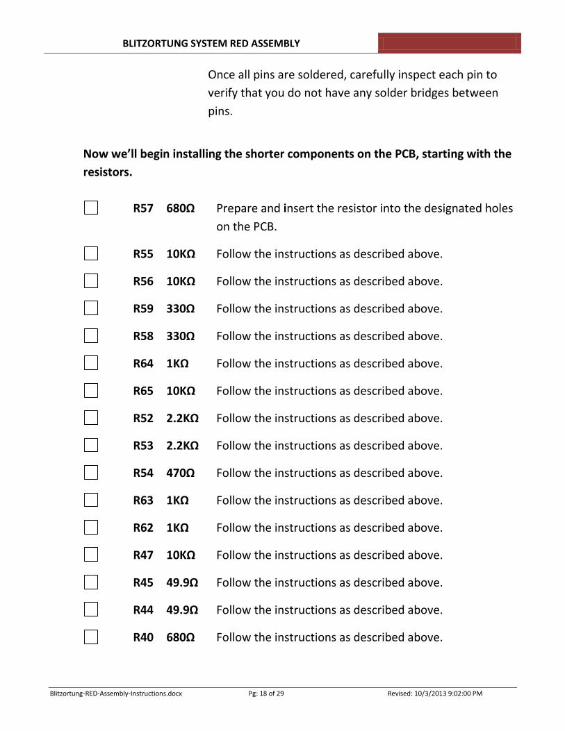
Once all pins are soldered, carefully inspect each pin to
verify that you do not have any solder bridges between
pins.
Now we’ll begin installing the shorter components on the PCB, starting with the
resistors.
R57 680Ω Prepare and insert the resistor into the designated holes
on the PCB.
R55 10KΩ Follow the instructions as described above.
R56 10KΩ Follow the instructions as described above.
R59 330Ω Follow the instructions as described above.
R58 330Ω Follow the instructions as described above.
R64 1KΩ Follow the instructions as described above.
R65 10KΩ Follow the instructions as described above.
R52 2.2KΩ Follow the instructions as described above.
R53 2.2KΩ Follow the instructions as described above.
R54 470Ω Follow the instructions as described above.
R63 1KΩ Follow the instructions as described above.
R62 1KΩ Follow the instructions as described above.
R47 10KΩ Follow the instructions as described above.
R45 49.9Ω Follow the instructions as described above.
R44 49.9Ω Follow the instructions as described above.
R40 680Ω Follow the instructions as described above.
BLITZORTUNG SYSTEM RED ASSEMBLY
Blitzortung-RED-Assembly-Instructions.docx Pg: 19 of 29 Revised: 10/3/2013 9:02:00 PM
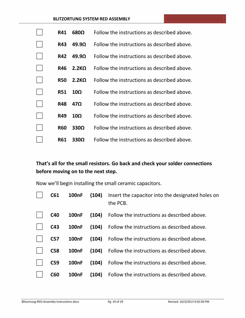
R41 680Ω Follow the instructions as described above.
R43 49.9Ω Follow the instructions as described above.
R42 49.9Ω Follow the instructions as described above.
R46 2.2KΩ Follow the instructions as described above.
R50 2.2KΩ Follow the instructions as described above.
R51 10Ω Follow the instructions as described above.
R48 47Ω Follow the instructions as described above.
R49 10Ω Follow the instructions as described above.
R60 330Ω Follow the instructions as described above.
R61 330Ω Follow the instructions as described above.
That’s all for the small resistors. Go back and check your solder connections
before moving on to the next step.
Now we’ll begin installing the small ceramic capacitors.
C61 100nF (104) Insert the capacitor into the designated holes on
the PCB.
C40 100nF (104) Follow the instructions as described above.
C43 100nF (104) Follow the instructions as described above.
C57 100nF (104) Follow the instructions as described above.
C58 100nF (104) Follow the instructions as described above.
C59 100nF (104) Follow the instructions as described above.
C60 100nF (104) Follow the instructions as described above.
BLITZORTUNG SYSTEM RED ASSEMBLY
Blitzortung-RED-Assembly-Instructions.docx Pg: 20 of 29 Revised: 10/3/2013 9:02:00 PM
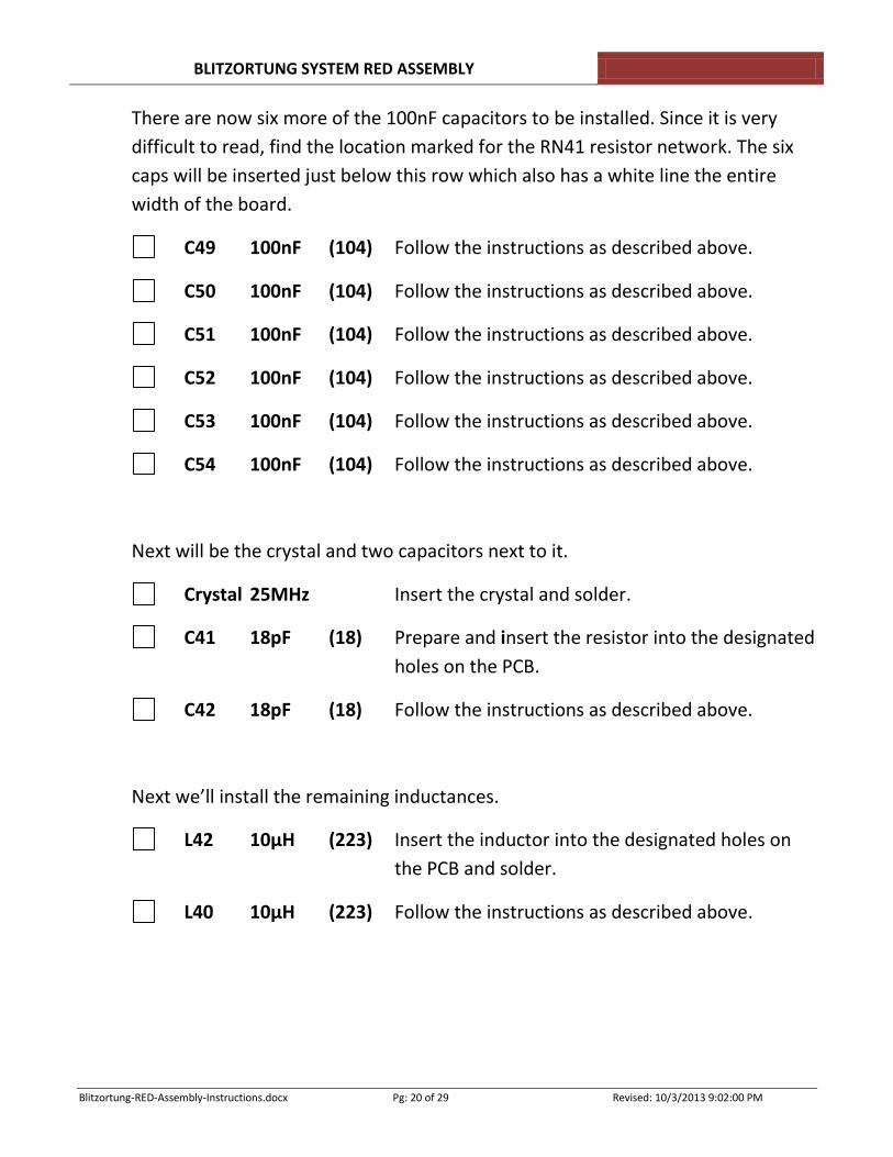
There are now six more of the 100nF capacitors to be installed. Since it is very
difficult to read, find the location marked for the RN41 resistor network. The six
caps will be inserted just below this row which also has a white line the entire
width of the board.
C49 100nF (104) Follow the instructions as described above.
C50 100nF (104) Follow the instructions as described above.
C51 100nF (104) Follow the instructions as described above.
C52 100nF (104) Follow the instructions as described above.
C53 100nF (104) Follow the instructions as described above.
C54 100nF (104) Follow the instructions as described above.
Next will be the crystal and two capacitors next to it.
Crystal 25MHz Insert the crystal and solder.
C41 18pF (18) Prepare and insert the resistor into the designated
holes on the PCB.
C42 18pF (18) Follow the instructions as described above.
Next we’ll install the remaining inductances.
L42 10μH (223) Insert the inductor into the designated holes on
the PCB and solder.
L40 10μH (223) Follow the instructions as described above.
BLITZORTUNG SYSTEM RED ASSEMBLY
Blitzortung-RED-Assembly-Instructions.docx Pg: 21 of 29 Revised: 10/3/2013 9:02:00 PM
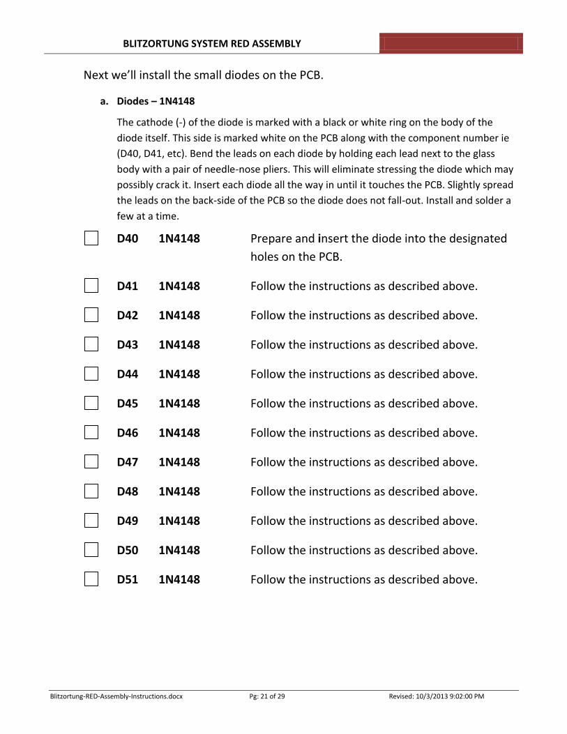
Next we’ll install the small diodes on the PCB.
a. Diodes – 1N4148
The cathode (-) of the diode is marked with a black or white ring on the body of the
diode itself. This side is marked white on the PCB along with the component number ie
(D40, D41, etc). Bend the leads on each diode by holding each lead next to the glass
body with a pair of needle-nose pliers. This will eliminate stressing the diode which may
possibly crack it. Insert each diode all the way in until it touches the PCB. Slightly spread
the leads on the back-side of the PCB so the diode does not fall-out. Install and solder a
few at a time.
D40 1N4148 Prepare and insert the diode into the designated
holes on the PCB.
D41 1N4148 Follow the instructions as described above.
D42 1N4148 Follow the instructions as described above.
D43 1N4148 Follow the instructions as described above.
D44 1N4148 Follow the instructions as described above.
D45 1N4148 Follow the instructions as described above.
D46 1N4148 Follow the instructions as described above.
D47 1N4148 Follow the instructions as described above.
D48 1N4148 Follow the instructions as described above.
D49 1N4148 Follow the instructions as described above.
D50 1N4148 Follow the instructions as described above.
D51 1N4148 Follow the instructions as described above.
BLITZORTUNG SYSTEM RED ASSEMBLY
Blitzortung-RED-Assembly-Instructions.docx Pg: 22 of 29 Revised: 10/3/2013 9:02:00 PM
b) Diodes – 1N5818
These diodes are prepared and installed the same as the 1N4148 diodes.
D52 1N5818 Prepare and insert the diode into the designated
holes on the PCB.
D53 1N5818 Follow the instructions as described above.
D54 1N5818 Follow the instructions as described above.
D55 1N5818 Follow the instructions as described above.
D56 1N5818 Follow the instructions as described above.
D57 1N5818 Follow the instructions as described above.
Next we’ll install the Resistor Network components.
NOTE: There are two identical RN41 items. While they can be installed in any
position, it is suggested the dot be placed towards the top of the PCB for
consistency. The RN41 items are located immediately next to the group of six
100nF capacitors. For the RN40 & RN42 networks, install them so the dot aligns
next to the white mark on the PCB.
RN41 1KΩ (B102) Follow the instructions as described above.
RN41 1KΩ (B102) Follow the instructions as described above.
RN40 100Ω (A101) Follow the instructions as described above.
RN42 10KΩ (A103) Follow the instructions as described above.
Next we’ll install the last LED.
Green LED GPS Lock Indicator
The long lead is inserted in the hole marked with a
white mark. Solder this LED before moving on to
the next item.
BLITZORTUNG SYSTEM RED ASSEMBLY
Blitzortung-RED-Assembly-Instructions.docx Pg: 23 of 29 Revised: 10/3/2013 9:02:00 PM
GPS SMA Connector Install the GPS SMA connector. Position the
connector so the threaded portion points away
from the PCB. Solder the center pin first and then
make certain the connector is fully seated on the
PCB. Solder remaining pins.
IC Socket Install and solder the IC socket for the ENC28J60 IC.
IC ENC28J60 Insert the IC into the socket. Ensure that all pins
are straight.
Ground Connector Insert the ground connector. Ensure it is aligned
with the wire connectors facing outward from the
PCB.
Serial Connector Insert the Serial Interface connector. The short
pins go in the holes. NOTE: Solder the middle pin
first and then position the connector so it is flush
with the PCB and the output pins are parallel with
the PCB. You have to reheat the center pin to get
this alignment correct. Then solder the remaining
pins.
Display Mounting Sockets These are shipped as 1x10 sockets. You will have
to snip off the last pin of each socket. Be careful
that you do not snip too much off. Smooth the
rough edge with a file. NOTE: You may want to
score between the last two pins on each socket
with a sharp knife before snipping them. This may
result in a cleaner break.
Socket 1 Insert the socket into its holes. Solder the pins.
Socket 2 Insert the socket into its holes. Solder the pins.
JP1 Jumper Install this jumper into its holes and Solder the
pins.
BLITZORTUNG SYSTEM RED ASSEMBLY
Blitzortung-RED-Assembly-Instructions.docx Pg: 24 of 29 Revised: 10/3/2013 9:02:00 PM
We’ll now install the sockets for the Discovery Board. First, insert the discovery
board into the two sockets before you place them on the controller board. This
will ensure correct pin alignment.
Insert the sockets, with the Discovery board attached, into the holes on the
Controller board. Lightly solder one of the end pins and then check to
ensure the socket is fully seated on the Controller board. Do this for both
sockets. Then solder a pin on the opposite end of the sockets you just
soldered. This will hold the sockets in position while soldering the
remaining pins.
Remove the discovery board now for the final component assembly of the
Controller board.
RJ45 Connector HanRun HR911105A
Remove the discovery board now for the final component assembly of the
Controller board.
RJ45 Connector Amp Input-A
Install the RJ45 connector and solder.
RJ45 Connector Amp Input-B
Install the RJ45 connector and solder.
Before installing the buzzer, you may clean the PCB with Denatured
Alcohol. This will remove any solder flux and debris left over from the
soldering process.
Buzzer Install the Buzzer and solder.
Final Inspection of the Controller Board
- Ensure all components have been soldered.
- Check for any solder bridges or debris left on the PCB.
BLITZORTUNG SYSTEM RED ASSEMBLY
Blitzortung-RED-Assembly-Instructions.docx Pg: 25 of 29 Revised: 10/3/2013 9:02:00 PM
INITIAL TESTING OF THE CONTROLLER BOARD
First Hardware Check:
If installed, remove the STM32F4DISCOVERY board and the Display as well.
Connect the 5V USB power supply to the mini USB connector on the
Controller board. If you are using the Global Top PAGH GPS module, the
Green GPS LED should start blinking.
Disconnect the 5V USB Power supply.
Mount the STM32F4 Discovery board. Ensure it is fully seated on both
sides. This may take some effort and going from side to side to accomplish.
Mount the Display board. Align the display so the pins marked 10-18 are
closest to the RJ45 LAN connector. Fully seat the display.
Plug-in the 5V USB Power supply to the Controller board mini USB
connector.
NOTE: Do not plug it into the discovery board. That connector will be used
only for programming the discovery board in later steps.
You should now see the green GPS LED on the controller board blinking as
well as other LEDs on the discovery board. The small Red LED on the
Discovery board nearest to the mini USB connector should be on steady
indicating the board is getting power.
This is the END of the initial testing phase.
Next, we’ll begin installing the firmware on the Discovery board.
NOTE: IMPORTANT - DO NOT connect either the Discovery or the Controller
board to your computer until instructed to do so in the following steps.
Doing so may cause unforeseen problems with software and firmware
installation.
BLITZORTUNG SYSTEM RED ASSEMBLY
Blitzortung-RED-Assembly-Instructions.docx Pg: 26 of 29 Revised: 10/3/2013 9:02:00 PM
STM32F4DISCOVERY BOARD FIRMWARE INSTALLATION
NOTE:
1. You must have purchased a Blitzortung Lightning Detection System and
have an Account ID BEFORE you will be able to perform any of the following
steps. If you have not purchased a system go to the main Blitzortung
website and view the information posted under the “Cover You Area” tab.
There are instructions on how to get further information in that section.
2. If you have purchased a system but do not have an Account ID, send a short
email requesting a new user account from the Blitzortung Administrator at:
Assuming you have already purchased a system and have an active Blitzortung
account:
Connect to the Blitzortung Website via your web browser:
http://www.blitzortung.org
Select the “Services” tab on the top of the screen.
Log-in to your account using your account id and password.
Once logged-in, click on the “Miscellaneous” tab on the left-side of your
screen. This will open a webpage with some links you will use to download
the STM32F4DISCOVERY board firmware. The section is labeled:
Firmware for System RED
STM32F4DISCOVERY: Firmware Directory
Click on the “Firmware Directory” link to get a list of available BIN files.
Select the latest firmware version. Click on the desired file and save this file
to your computer for later use (don’t forget where you put it).
BLITZORTUNG SYSTEM RED ASSEMBLY
Blitzortung-RED-Assembly-Instructions.docx Pg: 27 of 29 Revised: 10/3/2013 9:02:00 PM
Connect to the following website via your web browser to download the
program that will be used to flash your Discovery board:
http://www.st.com/web/en/catalog/tools/PF258168
Click on the download button at the bottom of the page and save the file to
your computer.
Unzip/extract the file you just downloaded and then run the STM32 ST-LINK
Utility_v3.1.0.exe file. This will install the program on your computer.
Follow the on-screen instructions and use the default values presented.
This downloaded file also includes the drivers you will need when you
connect the discovery board to your computer in later steps.
NOTE: The exact file name will vary as new versions of the software are released.
This particular version in this example was v3.1.0.
We are now ready to connect your STM32F4DISCOVERY board to your computer
so you can install the firmware.
Connect the 5V USB Power Supply cable to the Discovery board. It is NOT
necessary to remove the Discovery board from the controller board for this
procedure.
Connect a USB to mini-USB cable from your computer to the Discovery
board.
The computer should automatically detect the new device and install the device
driver that was just installed on your computer during the installation of the ST-
Link Utility program. This may take some time so be patient and watch your
screen for any messages. It should tell you when it is done installing the driver.
Once the driver is successfully installed, you can continue with the following
steps.
BLITZORTUNG SYSTEM RED ASSEMBLY
Blitzortung-RED-Assembly-Instructions.docx Pg: 28 of 29 Revised: 10/3/2013 9:02:00 PM
Find the “STM32 ST-LINK Utility” link on your desktop and double-click it to
start the program.
Select the “Target” tab then, select the “Program” item
From the menu, click Browse and select the Firmware…bin file you saved
earlier.
Check if the Start address is 0x08000000 and click on Start. This will begin
the flashing process. The process will take several seconds to complete.
Reset: If the CPU (on the Discovery board) doesn’t reset after flashing,
simply press the black button on the Discovery board.
This completes the flashing process.
Disconnect the 5V USB power supply and the computer USB cable from the
Discovery board.
You may now connect your controller board to your LAN connection (router) and
install the GPS antenna, if needed, along with the 5V USB power supply
connected to the Controller board (not the Discovery board).
If all goes well you should see information displayed on your display which will
allow you to set up your system with your own unique System ID and IP address.
More details on this part of the installation is being developed and will be added
to this document when it is completed. In the meantime, see the “Operating
Instructions” listed in the Blitzortung manual which can be found at
http://www.blitzortung.org/Webpages/index.php?lang=en&page=2®ion=3&subpage_0=30.
This web location will always have the latest version of the official Blitzortung
documentation.
SPECIAL NOTE: There appears to be a difference in the way the green LED works
when a GPS lock in attained. Earlier RED boards have this LED remaining ON when
a lock occurs. Later versions of the RED board now have the LED turn OFF when a
lock occurs. In both versions, the green LED blinks upon power up and while the
BLITZORTUNG SYSTEM RED ASSEMBLY
Blitzortung-RED-Assembly-Instructions.docx Pg: 29 of 29 Revised: 10/3/2013 9:02:00 PM
GPS module is searching for satellites. This was a design change that has just now
been revealed.
Sections yet to be written:
Section IV – Testing of your complete Kit
Section V – Troubleshooting
Section VI – Reference Information