Embed Size (px)
Citation preview

Users, Installation & Servicing
Instructions
MUST BE LEFT WITH THE USER
EKOS 16” Fuel Effect Options:
Coal Effect Pebble Effect
Beachcomber Effect Shoreline Effect
All available on NG & LPG
Control Options: Manual BM Control
Upgradeable Manual Control Remote Control (Response-S)
Optimum Control Trim Switch Control
Total Control
Installation Options: Installation using Freedom Surround
For use on Natural Gas (G20) at a supply pressure of 20mbar or Propane (G31) at a supply pressure of 37mbar in GB and IE
(Dependent upon model)
Manufacturer Contact Details: Burley Magiglo Lands End Way Oakham; Rutland LE15 6RB
Tel: +44 (0)1572 725570 Fax: +44 (0)1572 724390
General E-Mail: [email protected] Web Site: www.magiglo.co.uk Technical Support: Direct Dial on 01572 725570 or email: [email protected]
Magiglo Document Number:
MF444.4
Revision Date: 2nd April 2009
Copyright: This documentation is copyrighted by Burley Magiglo ©2009. No part of this document may be copied, photocopied or reproduced in any form or by any means without permission in writing from Burley Magiglo. Magiglo is a registered trademark of Burley Appliances Ltd
Service Warranty: In the unlikely event of a defect in materials or workmanship occurring within one year of purchase, Burley Magiglo will arrange to repair or replace the item free of charge. Any claims under this warranty must be made through the retailer from whom the product was purchased. As the purchaser’s contract of sale is with the retailer, Burley Magiglo are unable to enter into discussions with the purchaser until the retailer has inspected any claim and deemed it to be valid. Burley Magiglo reserve the right to refuse service or make a charge for any service call, when a defect is due to installation error or misuse. Extended warranty (if purchased) commences after the first year; please see separate registration for further information.
Appliance Details:
For future reference, please complete the following information at the time of installation. Model and Serial Number details may be found on the data plate as shown.
Serial Number
Model
Installation Date
Installed By
Model
Serial Number
Page i
Contents 1. GENERAL INFORMATION ........................................................................................................ 1
1.1. Important Note About ODS Pilot ................................................................................ 2 1.2. Fire Fret Dimensions .................................................................................................. 3
2. USER INSTRUCTIONS ............................................................................................................. 5 2.1. Lighting Procedure ..................................................................................................... 5
2.1.1. Lighting Procedure (Manual BM Control) ............................................................ 6 2.1.2. Lighting Procedure (Upgradeable Manual Control) ............................................. 7 2.1.3. Lighting Procedure (Remote Control) .................................................................. 8 2.1.4. Lighting Procedure (Optimum Control and Trim Switch Control) ......................... 9 2.1.5. Lighting Procedure (Total Control) ..................................................................... 10 2.1.6. Manual Operation (Total Control) ...................................................................... 11
2.2. Battery Replacement (Remote Control and Total Control) ...................................... 12 2.2.1. Handset .............................................................................................................. 12 2.2.2. Receiver Unit ..................................................................................................... 12
2.3. Battery Replacement (Optimum Control) ................................................................. 13 2.4. Battery Replacement (Trim Switch Control) ............................................................. 13 2.5. Fuel Effect Layout .................................................................................................... 14
2.5.1. Coal Effect Layout .............................................................................................. 15 2.5.2. Pebble Effect Layout .......................................................................................... 17 2.5.3. Beachcomber Effect & Shoreline Effect Layout ................................................. 19
2.6. Fitting the Trim ......................................................................................................... 21 2.7. Home Improvements ................................................................................................ 21 2.8. Cleaning and Care Instructions ................................................................................ 22
2.8.1. Cleaning the Fire-Bed with Imitation Fuel Effect ................................................ 22 2.8.2. Cleaning the Pilot ............................................................................................... 23 2.8.3. Cleaning the Fire Back ....................................................................................... 23 2.8.4. Painted Metal Surfaces ...................................................................................... 24 2.8.5. Care of Ceramic Backs ...................................................................................... 24
3. INSTALLATION INSTRUCTIONS .............................................................................................. 25 3.1. General Safety Requirements .................................................................................. 25 3.2. Flue Requirements ................................................................................................... 25
3.2.1. Masonry Flue ..................................................................................................... 25 3.2.2. Installation of Magiglo Ekos 16” into a 125mm (5”) Class 2 Metal Flue system 26 3.2.3. Installation Example using Existing Builder’s Opening ...................................... 27
3.3. General Dimensions ................................................................................................. 27 3.4. Technical Data ......................................................................................................... 28 3.5. Pressure Test Point Locations ................................................................................. 28 3.6. Appliance Location ................................................................................................... 29
3.6.1. Floor Level and Raised Fireplace Openings ...................................................... 30 3.6.2. Physical Barrier .................................................................................................. 31
3.7. Ventilation ................................................................................................................. 33 3.8. Contents Checklist ................................................................................................... 33 3.9. Installation Procedure............................................................................................... 34
3.9.1. Preparing the Firebox ........................................................................................ 34 3.9.2. Installation using Freedom Surround ................................................................. 35 3.9.3. Freedom Surround Installation (if applicable) .................................................... 36 3.9.4. Installation Using a Spacer Frame (if applicable) .............................................. 37 3.9.5. Preparing the Fireplace Opening (all models without Freedom Surround) ........ 38 3.9.6. Installing the Firebox (all models) ...................................................................... 39 3.9.7. Connecting the Gas Supply ............................................................................... 40 3.9.8. Continuation of Installation - Remote Control Model ......................................... 41
Page ii
3.9.9. Continuation of Installation - Optimum Control Model ....................................... 42 3.9.10. Continuation of Installation - Trim Switch Control Model ................................... 43 3.9.11. Continuation of Installation - Total Control Model .............................................. 43 3.9.12. Commissioning .................................................................................................. 44 3.9.13. Checking for Spillage ......................................................................................... 45 3.9.14. Instructing the User ............................................................................................ 45
4. SERVICING INSTRUCTIONS ................................................................................................... 47 4.1. General Requirements ............................................................................................. 47 4.2. Servicing Instructions ............................................................................................... 47 4.3. Replacing Parts ........................................................................................................ 48
4.3.1. Pilot Assembly Replacement ............................................................................. 48 4.3.2. Injector Replacement ......................................................................................... 48 4.3.3. Control Valve Replacement (BM or Mertik GV34) ............................................. 48 4.3.4. Motor Replacement (Remote/Optimum/Trim Switch Control Models) ............... 49 4.3.5. Replacing Mertik GV60 Valve (Total Control Model) ......................................... 50 4.3.6. Replacing the Receiver (Total Control Model) ................................................... 50 4.3.7. Programming Hand-set to Receiver) ................................................................. 50 4.3.8. Replacing the Ceramic Back and Sides ............................................................ 51
4.4. Installation and Operational Troubleshooting ........................................................... 52
Page 1
1. GENERAL INFORMATION Introduction
1. This appliance is suitable for installation in GB and IE and should be installed in accordance with the rules in force.
In GB, the installation must be carried out by a Gas Safe Registered Installer registered for working on this type of appliance. It must be carried out in accordance with the relevant requirements of the:
• Gas Safety (Installation and Use) Regulations. • The appropriate Building Regulations either The Building Regulations, The
Building Regulations (Scotland), Building Regulations (Northern Ireland). • The Current I.E.E. Wiring Regulations.
Where no specific instructions are given, reference should be made to the relevant British Standard Code of Practice (see item 2).
In IE, the installation must be carried out by a Competent Person and installed in accordance with the current edition of I.S.813 “Domestic Gas Installations”, the current Building Regulations and reference should be made to the current ETCI rules for electrical installation.
On completion of an installation in IE, it is necessary to complete a “Declaration of Conformity” to indicate compliance to I.S.813.
2. It is important for correct combustion of this fire that the imitation fuel is placed in accordance with the instructions given in this booklet. Only approved imitation fuel, available from Burley Magiglo., should be used with this appliance.
3. It is recommended that a fire guard complying with BS 8423 be fitted for the protection of young children, the elderly or infirm.
4. The user is warned not to throw any rubbish onto the fire or to disturb the fuel bed.
5. The user is advised that the ceramics used within this appliance require extra care whilst cleaning. Please refer to the Cleaning Instructions.
6. It is important for this fire to be serviced regularly. An annual service is recommended.
Efficiency Declaration
The efficiency of this appliance has been measured as specified in BS 7977: Part 1 and a value of up to 53.5%* was achieved. The gross calorific value of the fuel has been used for this efficiency calculation. The test data from which it has been calculated has been certified by Advantica Ltd. The efficiency value may be used in the UK Government’s Standard Assessment Procedure (SAP) for energy rating of dwellings (* 59.3% net efficiency).
Ventilation Requirements
1. This appliance does not normally require any ventilation in the room it is fitted in. In GB reference should be made to BS 5871 Part 2, and in IE reference should be made to the current edition of I.S.813 which makes clear the conditions that must be met to demonstrate that sufficient ventilation is available.
2. If provided, any purpose provided ventilation must be checked periodically to ensure it is free from obstructions.

Page 2
3. When fitting the fire in Northern Ireland (NI), purpose provided ventilation must be provided in accordance with the rules in force.
4. In other EC countries equivalent rules in force must be used.
5. It is important for the fire to be serviced regularly. An annual service is recommended.
Flue Requirements
Class 1 Masonry Flue - A flue having no cross sectional dimension less than 175mm (7”) e.g. 225mm (9”) by 225mm (9”) Masonry chimney or 175mm (7”) diameter clay liner.
Class 1 Masonry Flue with liner – A masonry flue having a flexible metal flue liner with a cross sectional dimension no less than 125mm.
Class 2 – A metal flue having no cross sectional dimension less than 125mm (5”).
Please refer to the full Flue and Chimney Requirements within the Installation Instruction section. The chimney must be checked regularly to ensure that all the products of combustion are entering the flue and there is no excessive build up of soot.
Gas Supply
1. This gas fire is suitable for use with either Natural Gas (G20) at 20mbar supply pressure or with Propane (G31) at 37mbar supply pressure.
2. Connection to the gas supply must be made using rigid or semi-rigid tubing.
3. A separate means of isolating the gas supply should be provided near to the appliance to facilitate servicing. An isolating valve has been supplied for this purpose.
Electrical Supply
Not applicable to this range of appliances.
1.1. Important Note About ODS Pilot This fire is fitted with an ODS pilot which causes the appliance to shut down in the event of a reduction of oxygen (e.g. caused by poor ventilation) in the room. Should this happen, follow the lighting instructions to re-light the fire. In the event that the fire should shut down again, do NOT attempt to re-light it but contact your gas installer for remedial action to be taken.
Under no circumstances should it be adjusted or put out of action by the installer or the user. If the pilot needs replacing, only the approved part (available from your supplier or Burley Magiglo.) should be fitted. Note: if any part of the pilot assembly becomes faulty the complete assembly will need replacing.
Page 3
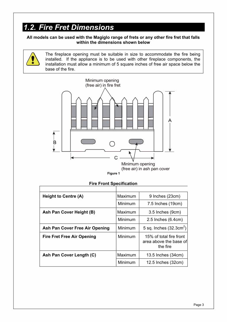
1.2. Fire Fret Dimensions All models can be used with the Magiglo range of frets or any other fire fret that falls
within the dimensions shown below
The fireplace opening must be suitable in size to accommodate the fire being installed. If the appliance is to be used with other fireplace components, the installation must allow a minimum of 5 square inches of free air space below the base of the fire.
Minimum opening (free air) in fire fret
Minimum opening (free air) in ash pan cover
Figure 1
Fire Front Specification Height to Centre (A) Maximum 9 Inches (23cm) Minimum 7.5 Inches (19cm)
Ash Pan Cover Height (B) Maximum 3.5 Inches (9cm) Minimum 2.5 Inches (6.4cm)
Ash Pan Cover Free Air Opening Minimum 5 sq. Inches (32.3cm2)
Fire Fret Free Air Opening Minimum 15% of total fire front area above the base of
the fire
Ash Pan Cover Length (C) Maximum 13.5 Inches (34cm) Minimum 12.5 Inches (32cm)

Page 4
This page is intentionally left blank
Page 5
2. USER INSTRUCTIONS
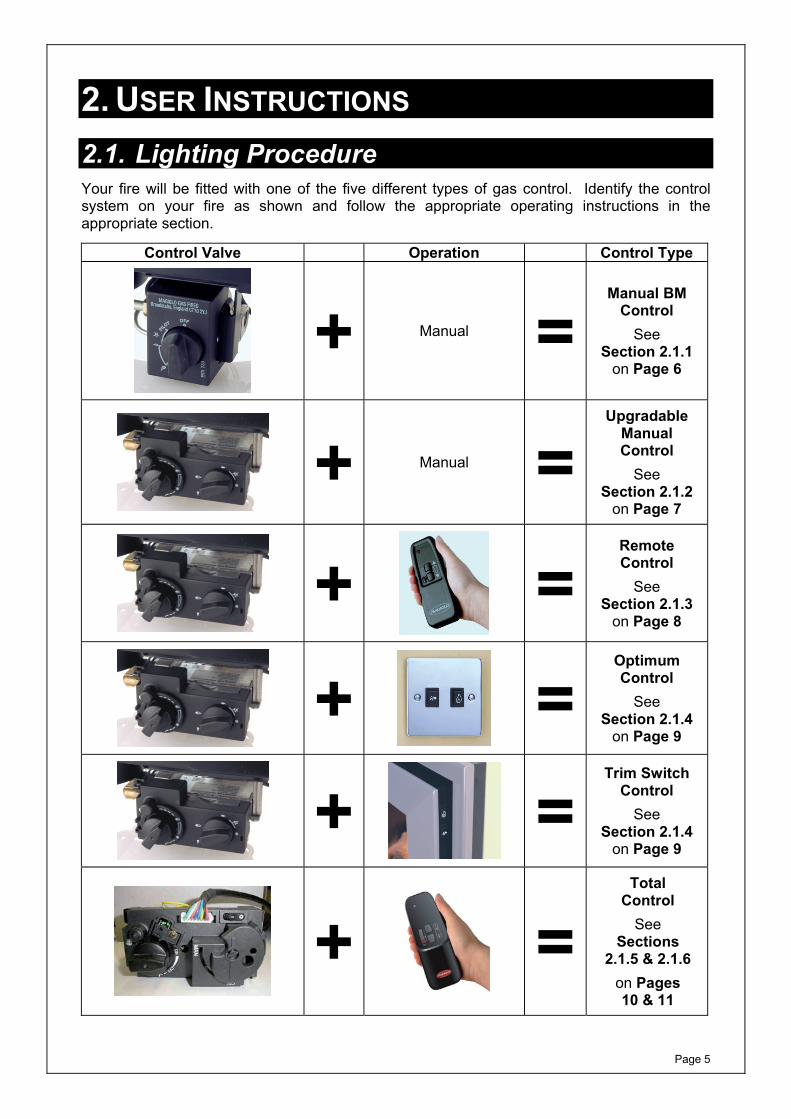
2.1. Lighting Procedure Your fire will be fitted with one of the five different types of gas control. Identify the control system on your fire as shown and follow the appropriate operating instructions in the appropriate section.
Control Valve Operation Control Type
+ Manual =
Manual BM Control
See Section 2.1.1
on Page 6
+
Manual =
Upgradable Manual Control
See Section 2.1.2
on Page 7
+
=
Remote Control
See Section 2.1.3
on Page 8
+
=
Optimum Control
See Section 2.1.4
on Page 9
+
=
Trim Switch Control
See Section 2.1.4
on Page 9
+
= Total
Control See
Sections 2.1.5 & 2.1.6
on Pages 10 & 11
Page 6
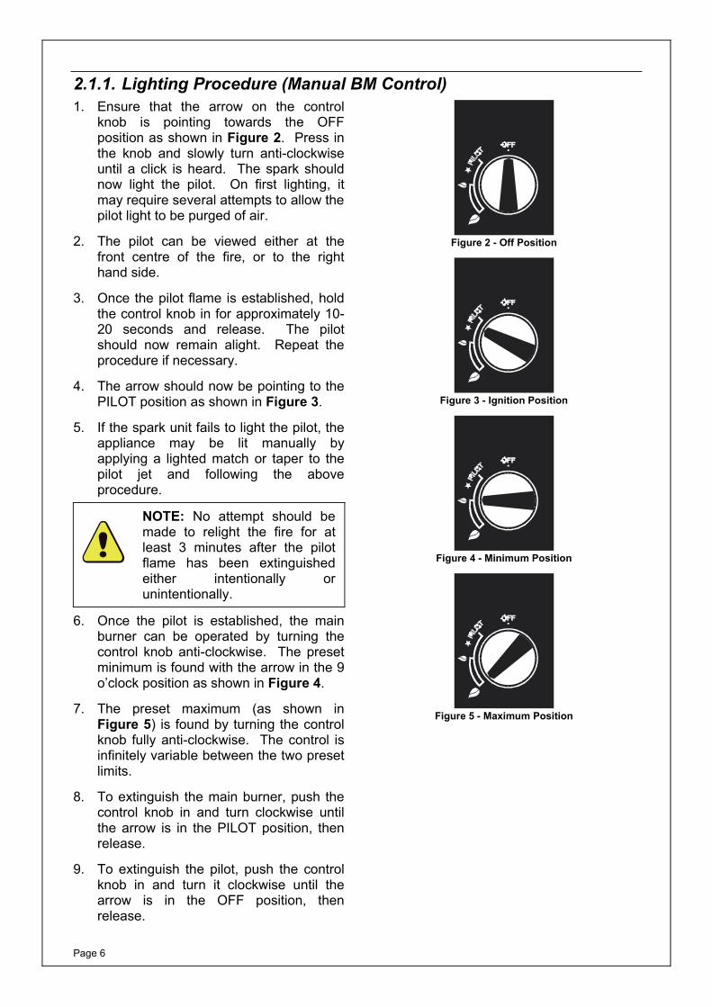
2.1.1. Lighting Procedure (Manual BM Control) 1. Ensure that the arrow on the control
knob is pointing towards the OFF position as shown in Figure 2. Press in the knob and slowly turn anti-clockwise until a click is heard. The spark should now light the pilot. On first lighting, it may require several attempts to allow the pilot light to be purged of air.
2. The pilot can be viewed either at the front centre of the fire, or to the right hand side.
3. Once the pilot flame is established, hold the control knob in for approximately 10-20 seconds and release. The pilot should now remain alight. Repeat the procedure if necessary.
4. The arrow should now be pointing to the PILOT position as shown in Figure 3.
5. If the spark unit fails to light the pilot, the appliance may be lit manually by applying a lighted match or taper to the pilot jet and following the above procedure.
NOTE: No attempt should be made to relight the fire for at least 3 minutes after the pilot flame has been extinguished either intentionally or unintentionally.
6. Once the pilot is established, the main burner can be operated by turning the control knob anti-clockwise. The preset minimum is found with the arrow in the 9 o’clock position as shown in Figure 4.
7. The preset maximum (as shown in Figure 5) is found by turning the control knob fully anti-clockwise. The control is infinitely variable between the two preset limits.
8. To extinguish the main burner, push the control knob in and turn clockwise until the arrow is in the PILOT position, then release.
9. To extinguish the pilot, push the control knob in and turn it clockwise until the arrow is in the OFF position, then release.
Figure 2 - Off Position
Figure 3 - Ignition Position
Figure 4 - Minimum Position
Figure 5 - Maximum Position
Page 7
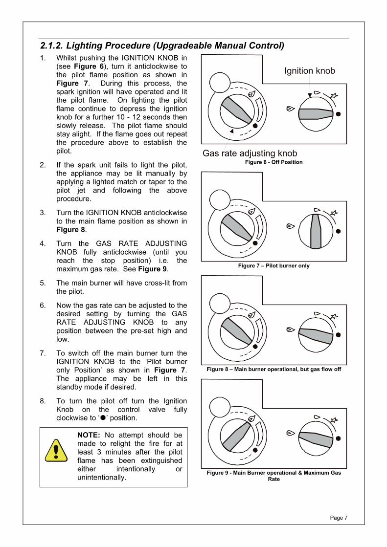
2.1.2. Lighting Procedure (Upgradeable Manual Control)1. Whilst pushing the IGNITION KNOB in
(see Figure 6), turn it anticlockwise to the pilot flame position as shown in Figure 7. During this process, the spark ignition will have operated and lit the pilot flame. On lighting the pilot flame continue to depress the ignition knob for a further 10 - 12 seconds then slowly release. The pilot flame should stay alight. If the flame goes out repeat the procedure above to establish the pilot.
2. If the spark unit fails to light the pilot, the appliance may be lit manually by applying a lighted match or taper to the pilot jet and following the above procedure.
3. Turn the IGNITION KNOB anticlockwise to the main flame position as shown in Figure 8.
4. Turn the GAS RATE ADJUSTING KNOB fully anticlockwise (until you reach the stop position) i.e. the maximum gas rate. See Figure 9.
5. The main burner will have cross-lit from the pilot.
6. Now the gas rate can be adjusted to the desired setting by turning the GAS RATE ADJUSTING KNOB to any position between the pre-set high and low.
7. To switch off the main burner turn the IGNITION KNOB to the ‘Pilot burner only Position’ as shown in Figure 7. The appliance may be left in this standby mode if desired.
8. To turn the pilot off turn the Ignition Knob on the control valve fully clockwise to ‘ ’ position.
NOTE: No attempt should be made to relight the fire for at least 3 minutes after the pilot flame has been extinguished either intentionally or unintentionally.
Ignition knob
Gas rate adjusting knob Figure 6 - Off Position
Figure 7 – Pilot burner only
Figure 8 – Main burner operational, but gas flow off
Figure 9 - Main Burner operational & Maximum Gas
Rate

Page 8
2.1.3. Lighting Procedure (Remote Control) 1. Press the bottom button on the remote
handset until clicking is heard on the valve, and the gas rate adjustment knob is at the off position.
2. With gas available at the valve press the IGNITION KNOB in and turn it anticlockwise to the pilot flame position. A click of the piezo igniter will be heard and a spark will appear at the electrode. At the same time the gas will flow to the pilot burner and should be ignited by the spark. Repeat the procedure until the pilot flame is established.
3. Keep the knob pressed in for a further 10 - 12 seconds and slowly release it. The pilot flame should stay alight. If the flame goes out repeat the procedure above to establish the pilot.
4. If the spark unit fails to light the pilot, the appliance may be lit manually by applying a lighted match or taper to the pilot jet and following the above procedure.
5. Turn the IGNITION KNOB anticlockwise to the Main Burner Operation position as shown in Figure 10.
6. Using the HANDSET (as shown in Figure 11) press and hold both the top and the small button together until the main burner goes to full rate and clicking can be heard from the valve. During this process the main burner will ignite from the pilot.
7. By pressing the two buttons together (to increase the gas rate) and the lower button only (to decrease the gas rate) the valve can be manipulated to select the desired gas rate between maximum and minimum. By pressing the buttons in short bursts you will be able to adjust the gas rate in small steps.
8. To turn the fire off, continuously press the lower button until the flame dies down and clicks can be heard from the valve. Release the button as soon as the clicks are heard.
9. The fire can safely be left in this position at all times, however to prevent unauthorised or accidental use (say by children) it is recommended to turn the IGNITION KNOB to the pilot flame position by turning it 90 degrees clockwise. To turn the pilot off, turn the IGNITION KNOB fully clockwise.
NOTE: The clicking sound made by the valve is the operation of the valve clutch, and indicates either maximum or off position.
IGNITIONKNOB
FULL RATEPOSITION
MAIN BURNEROFF POSITION
PILOT ONLYPOSITION
MAIN BURNEROPERATION
GAS RATEADJUSTMENTKNOB
Figure 10 – Gas Valve
Press these two buttons together to increase gas rate
Press this button to decrease gas rate
Figure 11 - Handset Operation
NOTE: No attempt should be made to relight the fire for at least 3 minutes after the pilot flame has been extinguished either intentionally or unintentionally.
Page 9
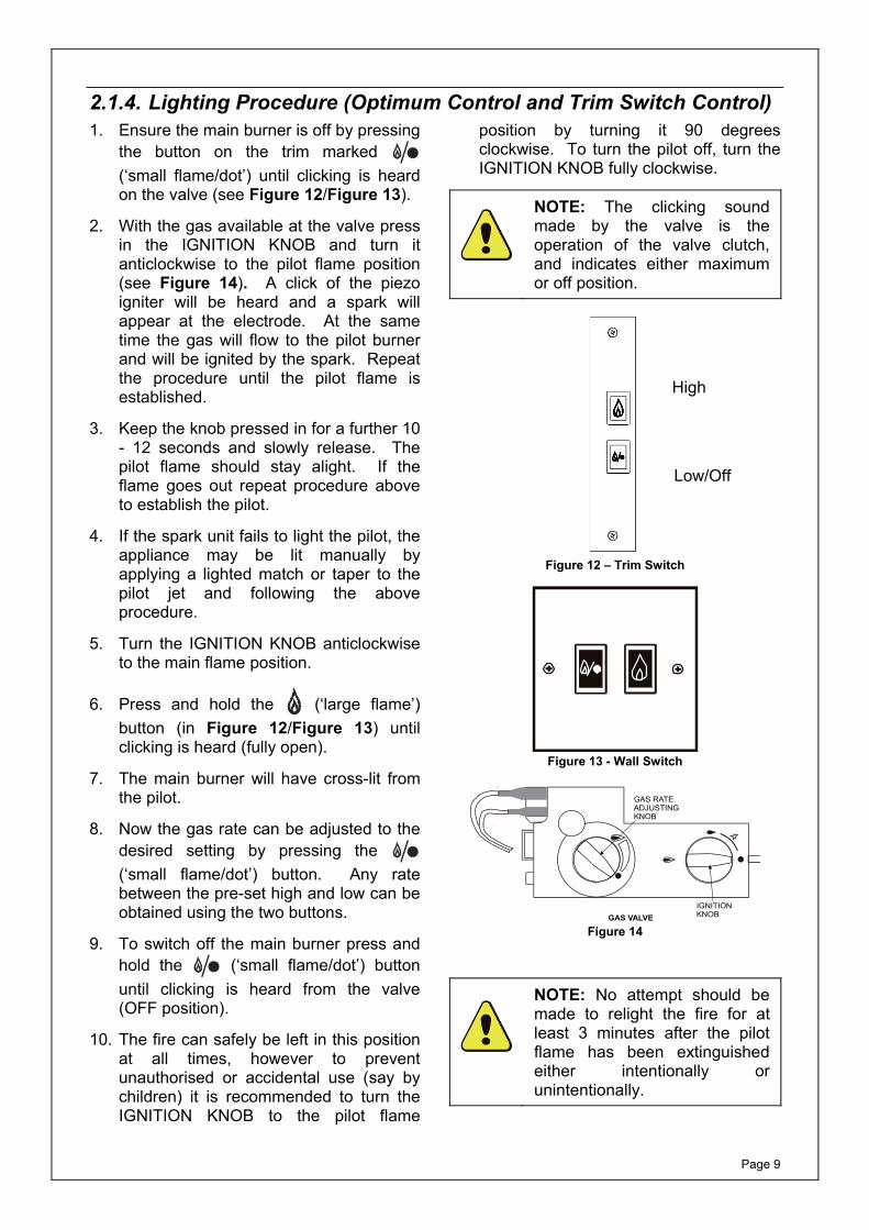
2.1.4. Lighting Procedure (Optimum Control and Trim Switch Control)1. Ensure the main burner is off by pressing
the button on the trim marked (‘small flame/dot’) until clicking is heard on the valve (see Figure 12/Figure 13).
2. With the gas available at the valve press in the IGNITION KNOB and turn it anticlockwise to the pilot flame position (see Figure 14). A click of the piezo igniter will be heard and a spark will appear at the electrode. At the same time the gas will flow to the pilot burner and will be ignited by the spark. Repeat the procedure until the pilot flame is established.
3. Keep the knob pressed in for a further 10 - 12 seconds and slowly release. The pilot flame should stay alight. If the flame goes out repeat procedure above to establish the pilot.
4. If the spark unit fails to light the pilot, the appliance may be lit manually by applying a lighted match or taper to the pilot jet and following the above procedure.
5. Turn the IGNITION KNOB anticlockwise to the main flame position.
6. Press and hold the (‘large flame’) button (in Figure 12/Figure 13) until clicking is heard (fully open).
7. The main burner will have cross-lit from the pilot.
8. Now the gas rate can be adjusted to the desired setting by pressing the (‘small flame/dot’) button. Any rate between the pre-set high and low can be obtained using the two buttons.
9. To switch off the main burner press and hold the (‘small flame/dot’) button until clicking is heard from the valve (OFF position).
10. The fire can safely be left in this position at all times, however to prevent unauthorised or accidental use (say by children) it is recommended to turn the IGNITION KNOB to the pilot flame
position by turning it 90 degrees clockwise. To turn the pilot off, turn the IGNITION KNOB fully clockwise.
NOTE: The clicking sound made by the valve is the operation of the valve clutch, and indicates either maximum or off position.
Figure 12 – Trim Switch
Figure 13 - Wall Switch
IGNITIONKNOB
GAS RATEADJUSTINGKNOB
GAS VALVE Figure 14
NOTE: No attempt should be made to relight the fire for at least 3 minutes after the pilot flame has been extinguished either intentionally or unintentionally.
High
Low/Off
Page 10
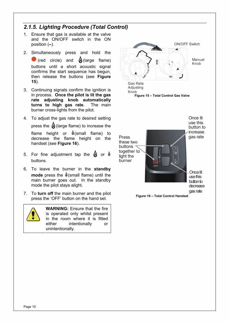
2.1.5. Lighting Procedure (Total Control) 1. Ensure that gas is available at the valve
and the ON/OFF switch in the ON position (–).
2. Simultaneously press and hold the
(red circle) and (large flame) buttons until a short acoustic signal confirms the start sequence has begun, then release the buttons (see Figure 15).
3. Continuing signals confirm the ignition is in process. Once the pilot is lit the gas rate adjusting knob automatically turns to high gas rate. The main burner cross-lights from the pilot.
4. To adjust the gas rate to desired setting
press the (large flame) to increase the
flame height or (small flame) to decrease the flame height on the handset (see Figure 16).
5. For fine adjustment tap the or buttons.
6. To leave the burner in the standby mode press the (small flame) until the main burner goes out. In the standby mode the pilot stays alight.
7. To turn off the main burner and the pilot press the ‘OFF’ button on the hand set.
WARNING: Ensure that the fire is operated only whilst present in the room where it is fitted either intentionally or unintentionally.
ManualKnob
Gas RateAdjustingKnob
ON/OFF Switch
NO
MAN
ON
OFF
Figure 15 – Total Control Gas Valve
Press these two buttons together to light the burner
Once lit use this button to increase gas rate
Once lit use this button to decrease gas rate
Figure 16 – Total Control Handset
Page 11
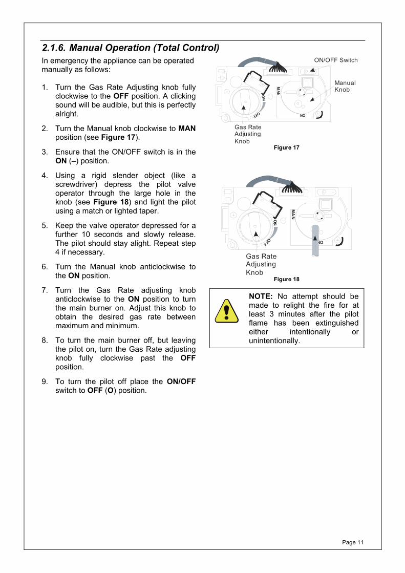
2.1.6. Manual Operation (Total Control) In emergency the appliance can be operated manually as follows: 1. Turn the Gas Rate Adjusting knob fully
clockwise to the OFF position. A clicking sound will be audible, but this is perfectly alright.
2. Turn the Manual knob clockwise to MAN position (see Figure 17).
3. Ensure that the ON/OFF switch is in the ON (–) position.
4. Using a rigid slender object (like a screwdriver) depress the pilot valve operator through the large hole in the knob (see Figure 18) and light the pilot using a match or lighted taper.
5. Keep the valve operator depressed for a further 10 seconds and slowly release. The pilot should stay alight. Repeat step 4 if necessary.
6. Turn the Manual knob anticlockwise to the ON position.
7. Turn the Gas Rate adjusting knob anticlockwise to the ON position to turn the main burner on. Adjust this knob to obtain the desired gas rate between maximum and minimum.
8. To turn the main burner off, but leaving the pilot on, turn the Gas Rate adjusting knob fully clockwise past the OFF position.
9. To turn the pilot off place the ON/OFF switch to OFF (O) position.
MAN
NO
ON/OFF Switch
ManualKnob
Gas RateAdjustingKnob
ON
OFF
Figure 17
MA
N
NO
Gas RateAdjustingKnob
ON
OFF
Figure 18
NOTE: No attempt should be made to relight the fire for at least 3 minutes after the pilot flame has been extinguished either intentionally or unintentionally.
Page 12
2.2. Battery Replacement (Remote Control and Total Control)
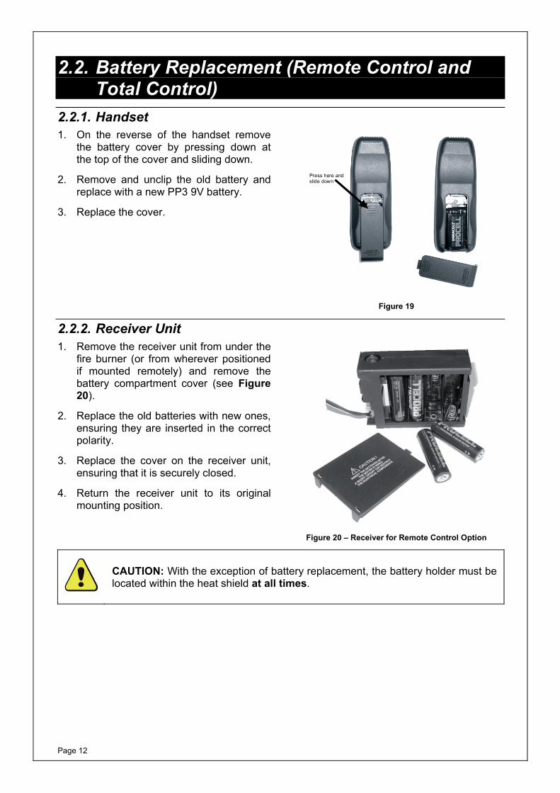
2.2.1. Handset 1. On the reverse of the handset remove
the battery cover by pressing down at the top of the cover and sliding down.
2. Remove and unclip the old battery and replace with a new PP3 9V battery.
3. Replace the cover.
Press here and slide down
Figure 19
2.2.2. Receiver Unit 1. Remove the receiver unit from under the
fire burner (or from wherever positioned if mounted remotely) and remove the battery compartment cover (see Figure 20).
2. Replace the old batteries with new ones, ensuring they are inserted in the correct polarity.
3. Replace the cover on the receiver unit, ensuring that it is securely closed.
4. Return the receiver unit to its original mounting position.
Figure 20 – Receiver for Remote Control Option
CAUTION: With the exception of battery replacement, the battery holder must be located within the heat shield at all times.
Page 13
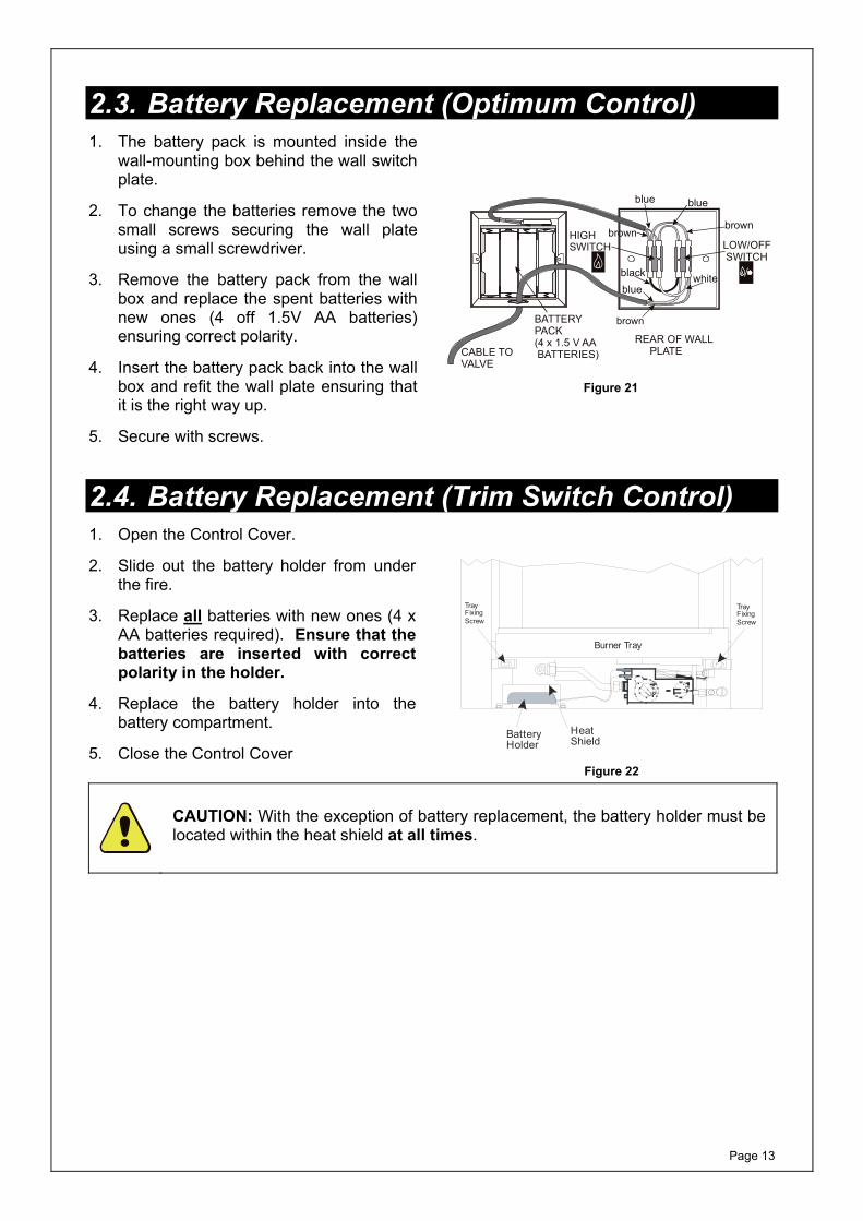
2.3. Battery Replacement (Optimum Control) 1. The battery pack is mounted inside the
wall-mounting box behind the wall switch plate.
2. To change the batteries remove the two small screws securing the wall plate using a small screwdriver.
3. Remove the battery pack from the wall box and replace the spent batteries with new ones (4 off 1.5V AA batteries) ensuring correct polarity.
4. Insert the battery pack back into the wall box and refit the wall plate ensuring that it is the right way up.
5. Secure with screws.
REAR OF WALL PLATECABLE TO
VALVE
BATTERYPACK(4 x 1.5 V AA BATTERIES)
LOW/OFFSWITCH
HIGHSWITCH
brownbrown
brown
blueblue
bluewhiteblack
Figure 21
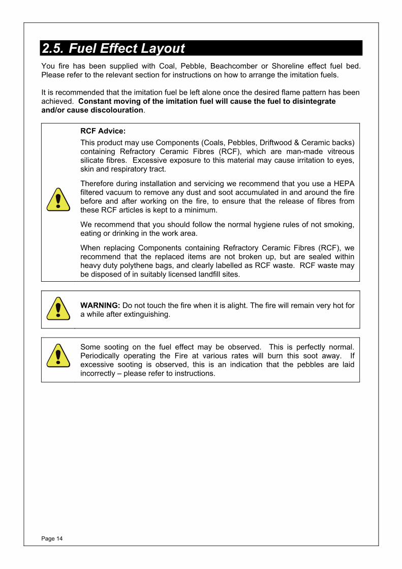
2.4. Battery Replacement (Trim Switch Control) 1. Open the Control Cover.
2. Slide out the battery holder from under the fire.
3. Replace all batteries with new ones (4 x AA batteries required). Ensure that the batteries are inserted with correct polarity in the holder.
4. Replace the battery holder into the battery compartment.
5. Close the Control Cover
HeatShield
BatteryHolder
Burner Tray
TrayFixingScrew
TrayFixingScrew
Figure 22
CAUTION: With the exception of battery replacement, the battery holder must be located within the heat shield at all times.
Page 14
2.5. Fuel Effect Layout You fire has been supplied with Coal, Pebble, Beachcomber or Shoreline effect fuel bed. Please refer to the relevant section for instructions on how to arrange the imitation fuels. It is recommended that the imitation fuel be left alone once the desired flame pattern has been achieved. Constant moving of the imitation fuel will cause the fuel to disintegrate and/or cause discolouration.
RCF Advice: This product may use Components (Coals, Pebbles, Driftwood & Ceramic backs) containing Refractory Ceramic Fibres (RCF), which are man-made vitreous silicate fibres. Excessive exposure to this material may cause irritation to eyes, skin and respiratory tract.
Therefore during installation and servicing we recommend that you use a HEPA filtered vacuum to remove any dust and soot accumulated in and around the fire before and after working on the fire, to ensure that the release of fibres from these RCF articles is kept to a minimum.
We recommend that you should follow the normal hygiene rules of not smoking, eating or drinking in the work area.
When replacing Components containing Refractory Ceramic Fibres (RCF), we recommend that the replaced items are not broken up, but are sealed within heavy duty polythene bags, and clearly labelled as RCF waste. RCF waste may be disposed of in suitably licensed landfill sites.
WARNING: Do not touch the fire when it is alight. The fire will remain very hot for a while after extinguishing.
Some sooting on the fuel effect may be observed. This is perfectly normal. Periodically operating the Fire at various rates will burn this soot away. If excessive sooting is observed, this is an indication that the pebbles are laid incorrectly – please refer to instructions.
Page 15
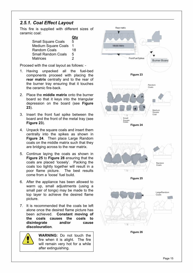
2.5.1. Coal Effect Layout This fire is supplied with different sizes of ceramic coal:
Qty Small Square Coals 5 Medium Square Coals 1 Random Coals 18 Small Random Coals 5 Matrices 2
Proceed with the coal layout as follows: - 1. Having unpacked all the fuel-bed
components proceed with placing the rear matrix centrally and to the rear of the burner tray ensuring that it touches the ceramic fire-back.
2. Place the middle matrix onto the burner board so that it keys into the triangular depression on the board (see Figure 23).
3. Insert the front fuel spike between the board and the front of the metal tray (see Figure 23).
4. Unpack the square coals and insert them centrally into the spikes as shown in Figure 24. Then place Large Random coals on the middle matrix such that they are bridging across to the rear matrix.
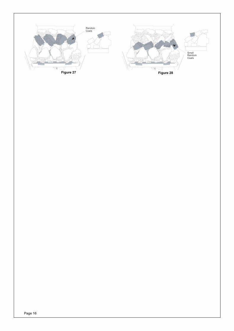
5. Continue laying the coals as shown in Figure 25 to Figure 28 ensuring that the coals are placed ‘loosely’. Packing the coals too tightly together will result in a poor flame picture. The best results come from a ‘loose’ fuel build.
6. After the appliance has been allowed to warm up, small adjustments (using a small pair of tongs) may be made to the top layer to achieve the desired flame picture.
7. It is recommended that the coals be left alone once the desired flame picture has been achieved. Constant moving of the coals causes the coals to disintegrate and/or cause discolouration.
WARNING: Do not touch the fire when it is alight. The fire will remain very hot for a while after extinguishing.
Rear matrix
Middle Matrix
Front Fuel SpikesBurner Board
Figure 23
MediumSquare Coal
SmallSquareCoals
Random Coals
Figure 24
Random Coals
Figure 25
LargeRandom Coals
Figure 26
Page 16
Random Coals
Figure 27
SmallRandom Coals
Figure 28
Page 17
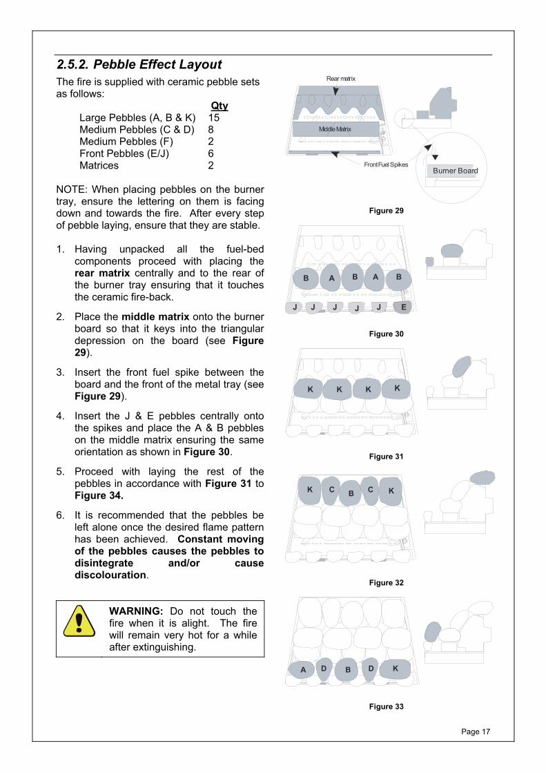
2.5.2. Pebble Effect Layout The fire is supplied with ceramic pebble sets as follows:
Qty Large Pebbles (A, B & K) 15 Medium Pebbles (C & D) 8 Medium Pebbles (F) 2 Front Pebbles (E/J) 6 Matrices 2
NOTE: When placing pebbles on the burner tray, ensure the lettering on them is facing down and towards the fire. After every step of pebble laying, ensure that they are stable. 1. Having unpacked all the fuel-bed
components proceed with placing the rear matrix centrally and to the rear of the burner tray ensuring that it touches the ceramic fire-back.
2. Place the middle matrix onto the burner board so that it keys into the triangular depression on the board (see Figure 29).
3. Insert the front fuel spike between the board and the front of the metal tray (see Figure 29).
4. Insert the J & E pebbles centrally onto the spikes and place the A & B pebbles on the middle matrix ensuring the same orientation as shown in Figure 30.
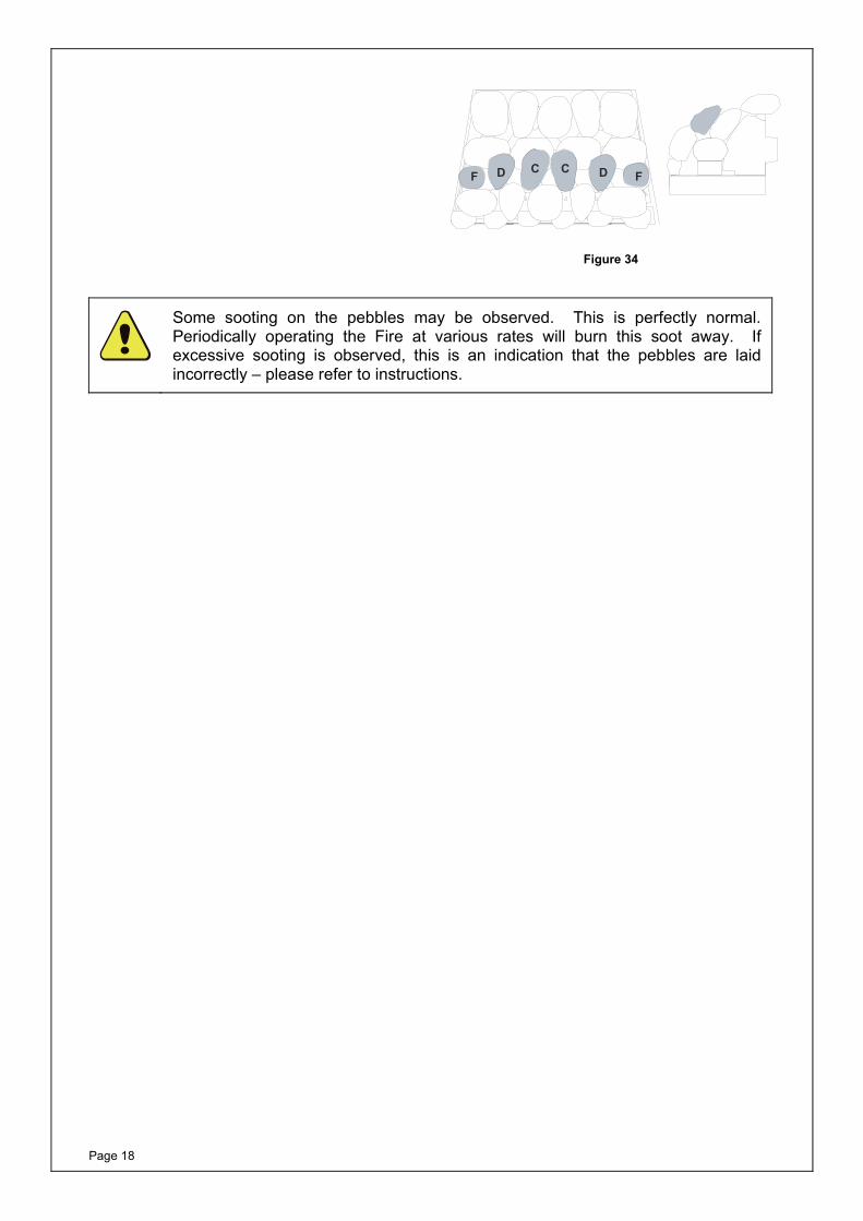
5. Proceed with laying the rest of the pebbles in accordance with Figure 31 to Figure 34.
6. It is recommended that the pebbles be left alone once the desired flame pattern has been achieved. Constant moving of the pebbles causes the pebbles to disintegrate and/or cause discolouration.
WARNING: Do not touch the fire when it is alight. The fire will remain very hot for a while after extinguishing.
Rear matrix
Middle Matrix
Front Fuel SpikesBurner Board
Figure 29
B A B A B
J J J J J E
Figure 30
K K K K
Figure 31
K KC CB
Figure 32
A D B D K
Figure 33
Page 18
F D C FDC
Figure 34
Some sooting on the pebbles may be observed. This is perfectly normal. Periodically operating the Fire at various rates will burn this soot away. If excessive sooting is observed, this is an indication that the pebbles are laid incorrectly – please refer to instructions.
Page 19
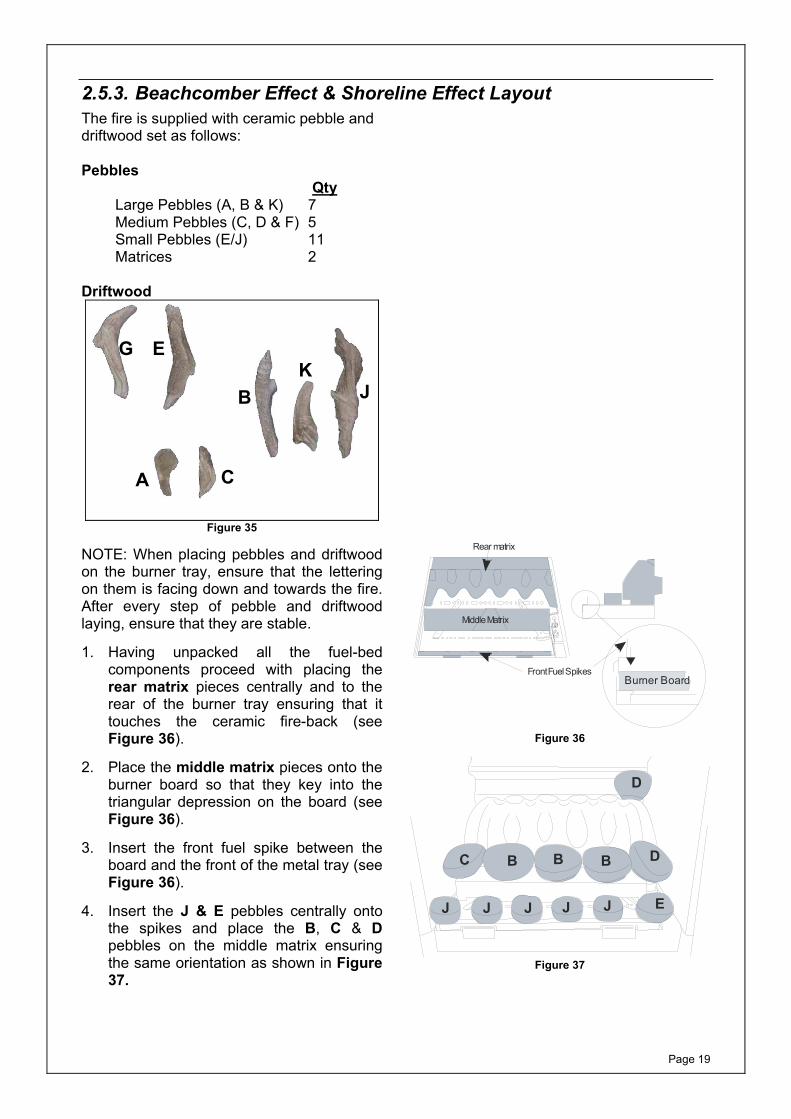
2.5.3. Beachcomber Effect & Shoreline Effect Layout The fire is supplied with ceramic pebble and driftwood set as follows: Pebbles
Qty Large Pebbles (A, B & K) 7 Medium Pebbles (C, D & F) 5 Small Pebbles (E/J) 11 Matrices 2
Driftwood
Figure 35
NOTE: When placing pebbles and driftwood on the burner tray, ensure that the lettering on them is facing down and towards the fire. After every step of pebble and driftwood laying, ensure that they are stable. 1. Having unpacked all the fuel-bed
components proceed with placing the rear matrix pieces centrally and to the rear of the burner tray ensuring that it touches the ceramic fire-back (see Figure 36).
2. Place the middle matrix pieces onto the burner board so that they key into the triangular depression on the board (see Figure 36).
3. Insert the front fuel spike between the board and the front of the metal tray (see Figure 36).
4. Insert the J & E pebbles centrally onto the spikes and place the B, C & D pebbles on the middle matrix ensuring the same orientation as shown in Figure 37.
Rear matrix
Middle Matrix
Front Fuel SpikesBurner Board
Figure 36
C B B B D
J J J J J E
D
Figure 37
A C
G E
B K
J
Page 20
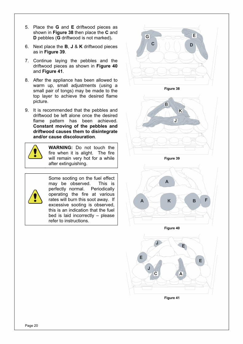
5. Place the G and E driftwood pieces as shown in Figure 38 then place the C and D pebbles (G driftwood is not marked).
6. Next place the B, J & K driftwood pieces as in Figure 39.
7. Continue laying the pebbles and the driftwood pieces as shown in Figure 40 and Figure 41.
8. After the appliance has been allowed to warm up, small adjustments (using a small pair of tongs) may be made to the top layer to achieve the desired flame picture.
9. It is recommended that the pebbles and driftwood be left alone once the desired flame pattern has been achieved. Constant moving of the pebbles and driftwood causes them to disintegrate and/or cause discolouration.
WARNING: Do not touch the fire when it is alight. The fire will remain very hot for a while after extinguishing.
Some sooting on the fuel effect may be observed. This is perfectly normal. Periodically operating the fire at various rates will burn this soot away. If excessive sooting is observed, this is an indication that the fuel bed is laid incorrectly – please refer to instructions.
C D
G E
Figure 38
BK
J
Figure 39
A K B F
A
Figure 40
J
J
E
EE
C A
Figure 41
Page 21
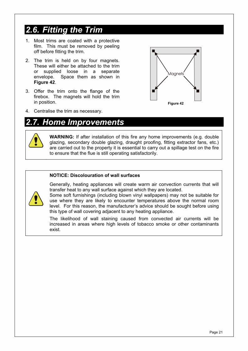
2.6. Fitting the Trim 1. Most trims are coated with a protective
film. This must be removed by peeling off before fitting the trim.
2. The trim is held on by four magnets. These will either be attached to the trim or supplied loose in a separate envelope. Space them as shown in Figure 42.
3. Offer the trim onto the flange of the firebox. The magnets will hold the trim in position.
4. Centralise the trim as necessary.
Magnets
Figure 42
2.7. Home Improvements
WARNING: If after installation of this fire any home improvements (e.g. double glazing, secondary double glazing, draught proofing, fitting extractor fans, etc.) are carried out to the property it is essential to carry out a spillage test on the fire to ensure that the flue is still operating satisfactorily.
NOTICE: Discolouration of wall surfaces
Generally, heating appliances will create warm air convection currents that will transfer heat to any wall surface against which they are located. Some soft furnishings (including blown vinyl wallpapers) may not be suitable for use where they are likely to encounter temperatures above the normal room level. For this reason, the manufacturer’s advice should be sought before using this type of wall covering adjacent to any heating appliance. The likelihood of wall staining caused from convected air currents will be increased in areas where high levels of tobacco smoke or other contaminants exist.
Page 22
2.8. Cleaning and Care Instructions
CAUTION: Ensure that the appliance is off (including the pilot light) and has completely cooled (off for at least 2 hours) before carrying out any cleaning or maintenance.
RCF Advice: This product may use Components (Coals, Pebbles, Driftwood & Ceramic backs) containing Refractory Ceramic Fibres (RCF), which are man-made vitreous silicate fibres. Excessive exposure to this material may cause irritation to eyes, skin and respiratory tract.
Therefore during installation and servicing we recommend that you use a HEPA filtered vacuum to remove any dust and soot accumulated in and around the fire before and after working on the fire, to ensure that the release of fibres from these RCF articles is kept to a minimum.
We recommend that you should follow the normal hygiene rules of not smoking, eating or drinking in the work area.
When replacing Components containing Refractory Ceramic Fibres (RCF), we recommend that the replaced items are not broken up, but are sealed within heavy duty polythene bags, and clearly labelled as RCF waste. RCF waste may be disposed of in suitably licensed landfill sites.
2.8.1. Cleaning the Fire-Bed with Imitation Fuel Effect1. If excessive debris is observed on the
imitation fuels or fire-bed, this must be removed before further using the fire.
2. Carefully remove all the imitation fuel from the fire-bed. Any soot or debris on the fuel can be gently brushed away with a soft brush - DO NOT use a vacuum cleaner.
3. Use a low powered HEPA filtered vacuum cleaner with a small nozzle to clean the burner board by gently sweeping the nozzle above the surface of the board. Clean the ports (small holes on the board) in a similar fashion.
4. Relay the imitation fuel after cleaning in accordance with the layout instructions in this booklet.
5. When satisfactory flame appearance has been achieved after positioning the coals/pebbles/driftwood, they should not be moved unnecessarily. Constant moving of the imitation fuels will damage and/or cause discolouration.
Page 23
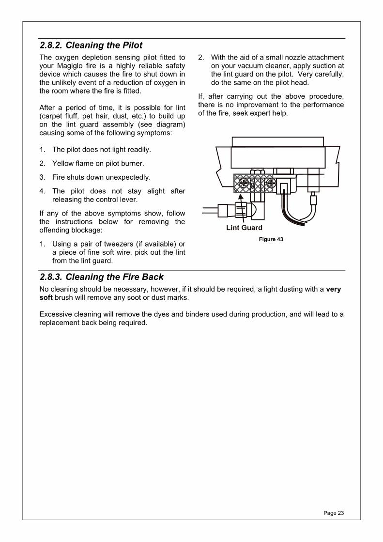
2.8.2. Cleaning the Pilot The oxygen depletion sensing pilot fitted to your Magiglo fire is a highly reliable safety device which causes the fire to shut down in the unlikely event of a reduction of oxygen in the room where the fire is fitted. After a period of time, it is possible for lint (carpet fluff, pet hair, dust, etc.) to build up on the lint guard assembly (see diagram) causing some of the following symptoms: 1. The pilot does not light readily.
2. Yellow flame on pilot burner.
3. Fire shuts down unexpectedly.
4. The pilot does not stay alight after releasing the control lever.
If any of the above symptoms show, follow the instructions below for removing the offending blockage:
1. Using a pair of tweezers (if available) or a piece of fine soft wire, pick out the lint from the lint guard.
2. With the aid of a small nozzle attachment on your vacuum cleaner, apply suction at the lint guard on the pilot. Very carefully, do the same on the pilot head.
If, after carrying out the above procedure, there is no improvement to the performance of the fire, seek expert help.
Lint Guard Figure 43
2.8.3. Cleaning the Fire Back No cleaning should be necessary, however, if it should be required, a light dusting with a very soft brush will remove any soot or dust marks. Excessive cleaning will remove the dyes and binders used during production, and will lead to a replacement back being required.
Page 24
2.8.4. Painted Metal Surfaces These surfaces should be dusted regularly and any marks removed with a soft damp cloth. 2.8.5. Care of Ceramic Backs The ceramic fireback on this appliance must NOT be sprayed with any type of solvent-based high temperature paint. The very high temperatures produced within the appliance will cause the paint to bubble and/or burn off rendering the fireback looking unsightly. Minor surface scuffs may be treated using a water based touch up stain available at Magiglo fire retailers.
Extreme care should be taken when handling and installing products containing ceramic interiors, so as not to cause damage.
Page 25
3. INSTALLATION INSTRUCTIONS Before installation, ensure that the local distribution conditions (identification of the type of gas and pressure and the adjustment of the appliance are compatible)
3.1. General Safety Requirements The installation of the fire in GB should follow the recommendations of the following current British Standards:
BS 5871: Pt 2 Installation of Inset live fuel effect gas fires. BS 6891 Pipe work Installation BS 5440: Pts 1 & 2 Flues and Ventilation BS EN 1856 Chimneys - Requirements for metal chimneys - System chimney
products BS 715 Metal flue boxes BS EN 1858 Chimney – Components – Concrete flue blocks In IE equivalent rules in force must be used.
3.2. Flue Requirements 3.2.1. Masonry Flue 1. The flue serving this appliance shall have no cross sectional dimension less than 175mm
(7”) e.g. 225mm (9”) by 225mm (9”) Masonry chimney or 175mm (7”) diameter clay liner and a minimum equivalent height of 3m (10ft). For installation in GB, please refer to BS 5871 Part 2 for further information. For installation in IE, refer to the current edition of I.S.813 “Domestic Gas Installations”.
2. A faulty flue or chimney may result in smoke and fumes entering the room.
3. The flue should be sound, free from obstructions and, if it has previously been used with a solid fuel or oil fired appliance, it should be swept before installing this gas fire. The flue must be inspected annually to ensure continued clearance of combustion products.
4. Any flue damper plates or obstructions etc. must be removed and no restrictor plates shall be fitted. Where removal is not practical, the damper plate/restrictor must be fixed permanently in the fully open position.
Note: To comply with the expression “permanently fixed in the open position”, a mechanical fixing that prevents user intervention should be used e.g. requires the use of tools for removal.
5. It is recommended that a smoke test be carried out before installation to ensure that there is no spillage of fumes into the room. If spillage occurs this problem must be rectified before commencing installation.
6. The flue must serve only one appliance.
Page 26
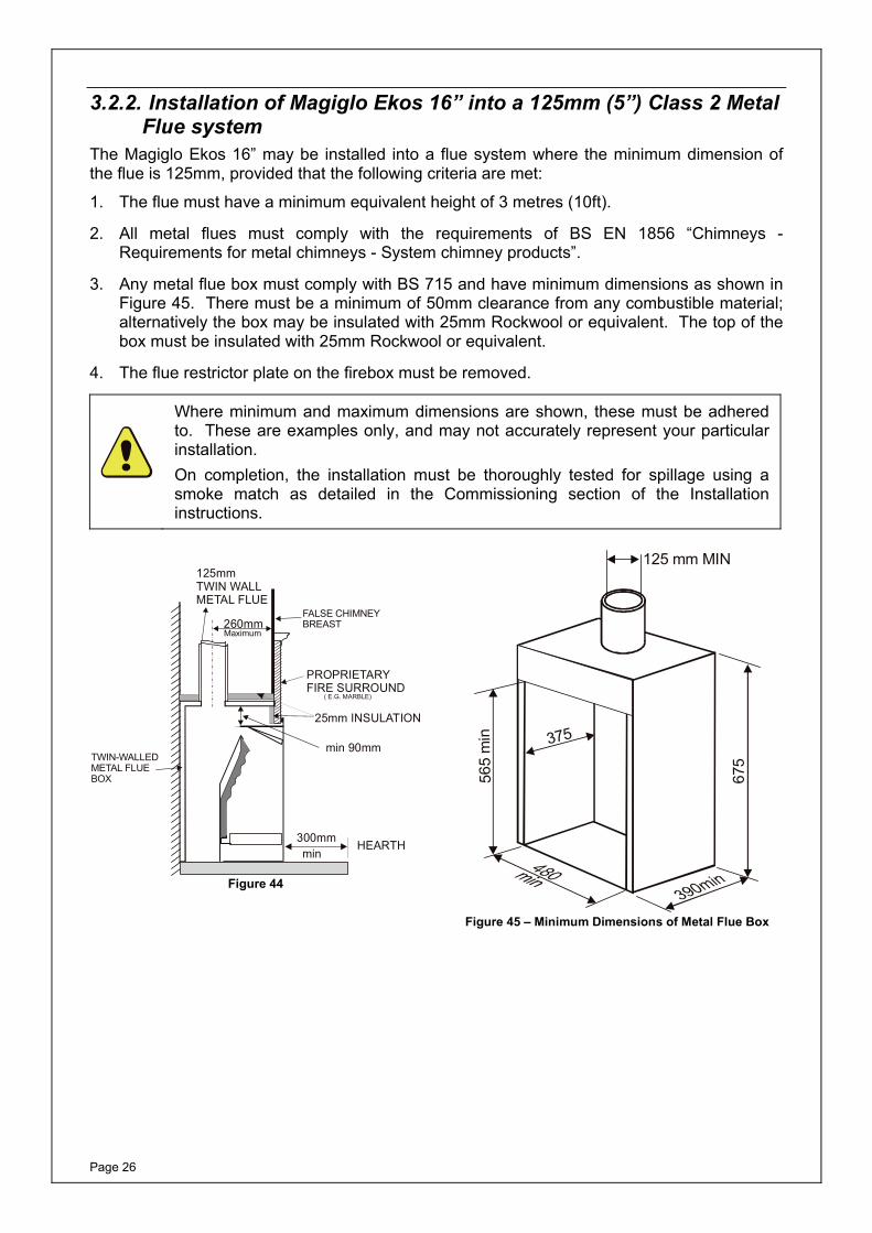
3.2.2. Installation of Magiglo Ekos 16” into a 125mm (5”) Class 2 Metal Flue system
The Magiglo Ekos 16” may be installed into a flue system where the minimum dimension of the flue is 125mm, provided that the following criteria are met:
1. The flue must have a minimum equivalent height of 3 metres (10ft).
2. All metal flues must comply with the requirements of BS EN 1856 “Chimneys - Requirements for metal chimneys - System chimney products”.
3. Any metal flue box must comply with BS 715 and have minimum dimensions as shown in Figure 45. There must be a minimum of 50mm clearance from any combustible material; alternatively the box may be insulated with 25mm Rockwool or equivalent. The top of the box must be insulated with 25mm Rockwool or equivalent.
4. The flue restrictor plate on the firebox must be removed.
Where minimum and maximum dimensions are shown, these must be adhered to. These are examples only, and may not accurately represent your particular installation. On completion, the installation must be thoroughly tested for spillage using a smoke match as detailed in the Commissioning section of the Installation instructions.
PROPRIETARYFIRE SURROUND
25mm INSULATION
300mmmin
HEARTH
125mmTWIN WALLMETAL FLUE
min 90mm
( E.G. MARBLE)
FALSE CHIMNEYBREAST
TWIN-WALLEDMETAL FLUEBOX
260mmMaximum
Figure 44
125 mm MIN
565
min 375
675
Figure 45 – Minimum Dimensions of Metal Flue Box
Page 27
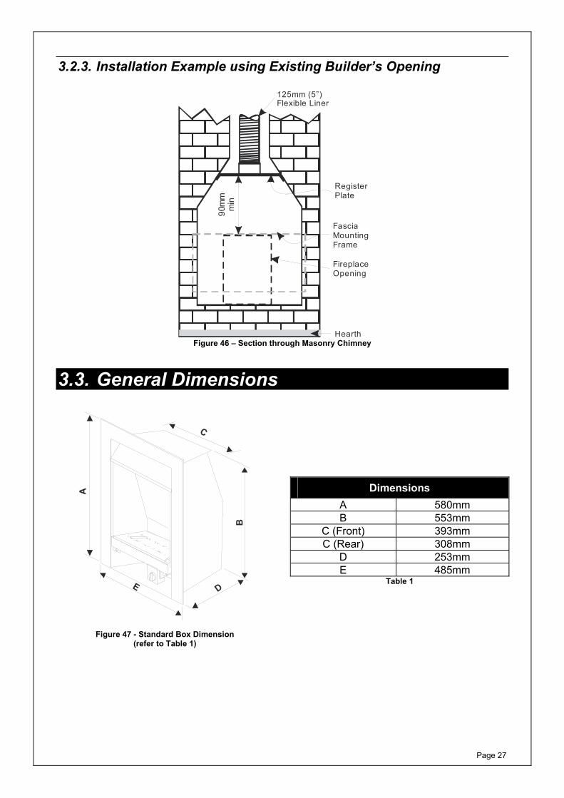
3.2.3. Installation Example using Existing Builder’s Opening
90m
m m
in
125mm (5”)Flexible Liner
FasciaMountingFrame
Hearth
RegisterPlate
FireplaceOpening
Figure 46 – Section through Masonry Chimney
3.3. General Dimensions
A
E D
B
C
Figure 47 - Standard Box Dimension (refer to Table 1)
Dimensions A 580mm B 553mm
C (Front) 393mmC (Rear) 308mm
D 253mmE 485mm
Table 1
Page 28
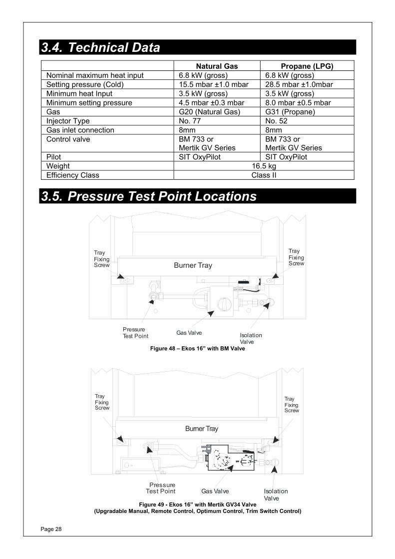
3.4. Technical Data Natural Gas Propane (LPG) Nominal maximum heat input 6.8 kW (gross) 6.8 kW (gross) Setting pressure (Cold) 15.5 mbar ±1.0 mbar 28.5 mbar ±1.0mbar Minimum heat Input 3.5 kW (gross) 3.5 kW (gross) Minimum setting pressure 4.5 mbar ±0.3 mbar 8.0 mbar ±0.5 mbarGas G20 (Natural Gas) G31 (Propane) Injector Type No. 77 No. 52 Gas inlet connection 8mm 8mm Control valve BM 733 or
Mertik GV SeriesBM 733 or Mertik GV Series
Pilot SIT OxyPilot SIT OxyPilot Weight 16.5 kg Efficiency Class Class II
3.5. Pressure Test Point Locations
PressureTest Point Gas Valve
TrayFixingScrew
TrayFixingScrewBurner Tray
IsolationValve
Figure 48 – Ekos 16” with BM Valve
PressureTest Point
Burner Tray
TrayFixingScrew
TrayFixingScrew
Gas Valve IsolationValve
Figure 49 - Ekos 16” with Mertik GV34 Valve (Upgradable Manual, Remote Control, Optimum Control, Trim Switch Control)
Page 29
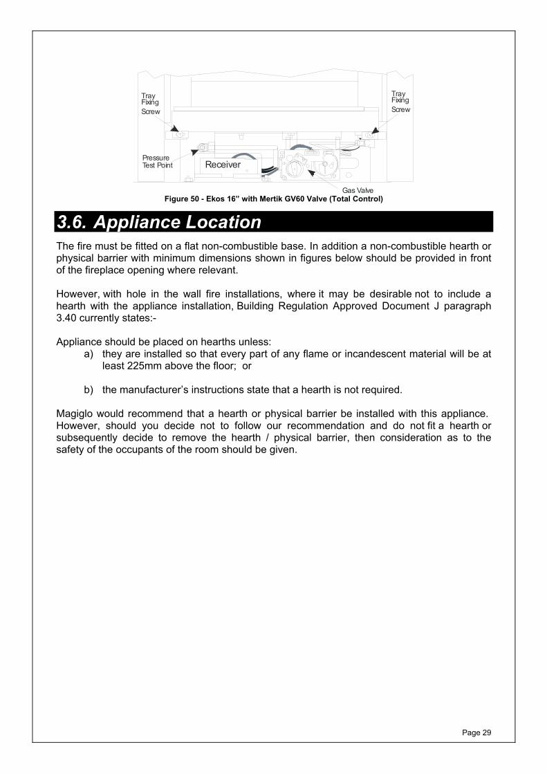
Gas Valve
PressureTest Point Receiver
TrayFixingScrew
TrayFixingScrew
Figure 50 - Ekos 16” with Mertik GV60 Valve (Total Control)
3.6. Appliance Location The fire must be fitted on a flat non-combustible base. In addition a non-combustible hearth or physical barrier with minimum dimensions shown in figures below should be provided in front of the fireplace opening where relevant. However, with hole in the wall fire installations, where it may be desirable not to include a hearth with the appliance installation, Building Regulation Approved Document J paragraph 3.40 currently states:- Appliance should be placed on hearths unless:
a) they are installed so that every part of any flame or incandescent material will be at least 225mm above the floor; or
b) the manufacturer’s instructions state that a hearth is not required.
Magiglo would recommend that a hearth or physical barrier be installed with this appliance. However, should you decide not to follow our recommendation and do not fit a hearth or subsequently decide to remove the hearth / physical barrier, then consideration as to the safety of the occupants of the room should be given.
Page 30
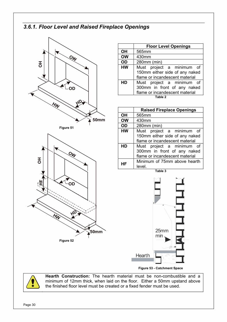
3.6.1. Floor Level and Raised Fireplace Openings
OW
OH
OD
HW HD
50mm
Figure 51
OW
OH
OD
HW HD
50mm
HF
Figure 52
Floor Level Openings OH 565mmOW 430mmOD 280mm (min) HW Must project a minimum of
150mm either side of any naked flame or incandescent material
HD Must project a minimum of 300mm in front of any naked flame or incandescent material
Table 2
Raised Fireplace Openings OH 565mmOW 430mmOD 280mm (min) HW Must project a minimum of
150mm either side of any naked flame or incandescent material
HD Must project a minimum of 300mm in front of any naked flame or incandescent material
HF Minimum of 75mm above hearth level.
Table 3
Hearth
25mmmin
Figure 53 - Catchment Space
Hearth Construction: The hearth material must be non-combustible and a minimum of 12mm thick, when laid on the floor. Either a 50mm upstand above the finished floor level must be created or a fixed fender must be used.
Page 31
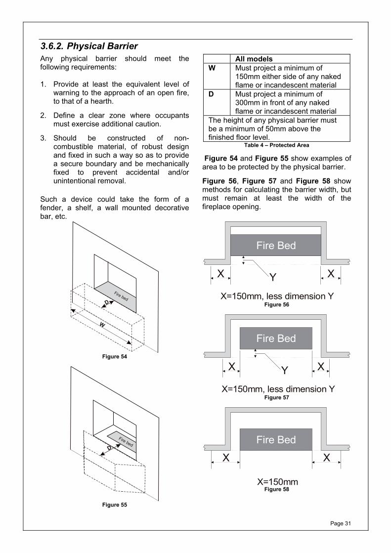
3.6.2. Physical BarrierAny physical barrier should meet the following requirements: 1. Provide at least the equivalent level of
warning to the approach of an open fire, to that of a hearth.
2. Define a clear zone where occupants must exercise additional caution.
3. Should be constructed of non-combustible material, of robust design and fixed in such a way so as to provide a secure boundary and be mechanically fixed to prevent accidental and/or unintentional removal.
Such a device could take the form of a fender, a shelf, a wall mounted decorative bar, etc.
All models W Must project a minimum of
150mm either side of any naked flame or incandescent material
D Must project a minimum of 300mm in front of any naked flame or incandescent material
The height of any physical barrier must be a minimum of 50mm above the finished floor level.
Table 4 – Protected Area
Figure 54 and Figure 55 show examples of area to be protected by the physical barrier.
Figure 56, Figure 57 and Figure 58 show methods for calculating the barrier width, but must remain at least the width of the fireplace opening.
W
D
Fire bed
Figure 54
D
Fire bed
Figure 55
Fire Bed
X XY
X=150mm, less dimension Y Figure 56
Fire Bed
X XY
X=150mm, less dimension Y Figure 57
Fire Bed
X X
X=150mm Figure 58
Page 32
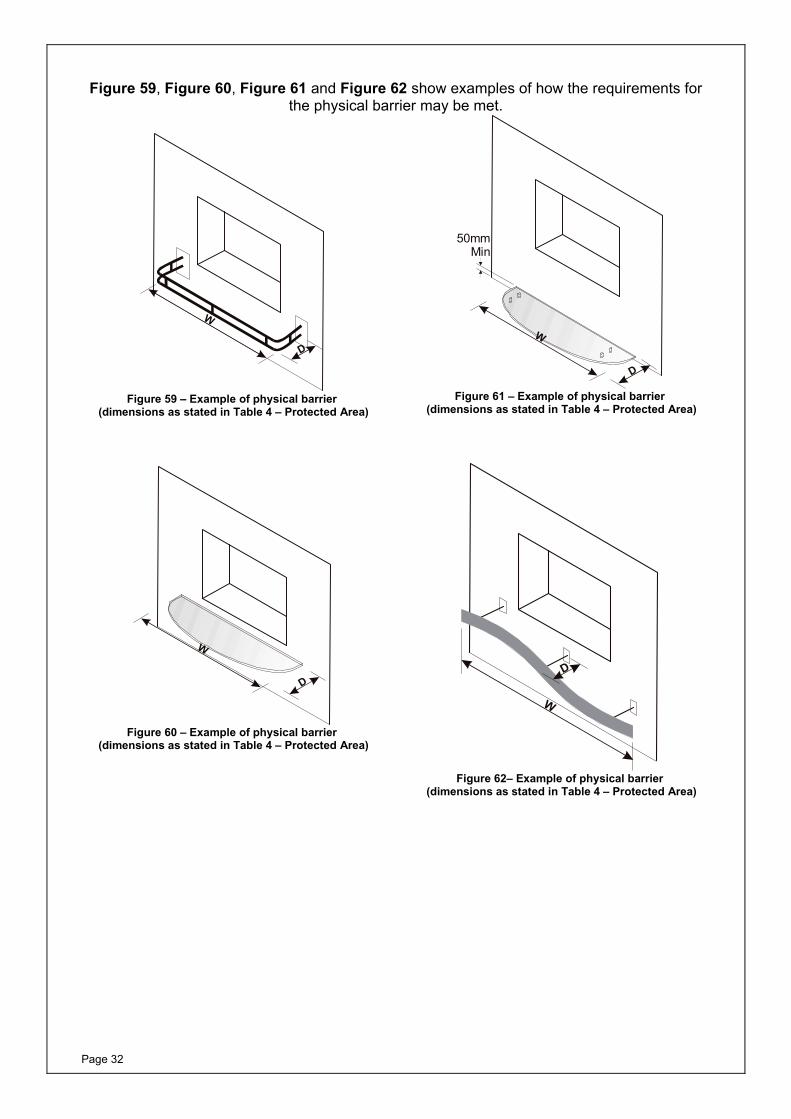
Figure 59, Figure 60, Figure 61 and Figure 62 show examples of how the requirements for the physical barrier may be met.
D
W
Figure 59 – Example of physical barrier
(dimensions as stated in Table 4 – Protected Area)
D
W
Figure 60 – Example of physical barrier
(dimensions as stated in Table 4 – Protected Area)
D
W
50mmMin
Figure 61 – Example of physical barrier
(dimensions as stated in Table 4 – Protected Area)
W
D
Figure 62– Example of physical barrier
(dimensions as stated in Table 4 – Protected Area)
Page 33
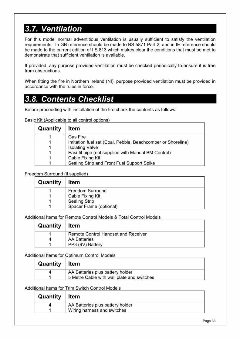
3.7. Ventilation For this model normal adventitious ventilation is usually sufficient to satisfy the ventilation requirements. In GB reference should be made to BS 5871 Part 2, and in IE reference should be made to the current edition of I.S.813 which makes clear the conditions that must be met to demonstrate that sufficient ventilation is available. If provided, any purpose provided ventilation must be checked periodically to ensure it is free from obstructions. When fitting the fire in Northern Ireland (NI), purpose provided ventilation must be provided in accordance with the rules in force.
3.8. Contents Checklist Before proceeding with installation of the fire check the contents as follows: Basic Kit (Applicable to all control options)
Quantity Item 1 Gas Fire 1 Imitation fuel set (Coal, Pebble, Beachcomber or Shoreline) 1 Isolating Valve 1 Easi-fit pipe (not supplied with Manual BM Control) 1 Cable Fixing Kit1 Sealing Strip and Front Fuel Support Spike
Freedom Surround (if supplied)
Quantity Item 1 Freedom Surround1 Cable Fixing Kit 1 Sealing Strip 1 Spacer Frame (optional)
Additional Items for Remote Control Models & Total Control Models
Quantity Item 1 Remote Control Handset and Receiver 4 AA Batteries 1 PP3 (9V) Battery
Additional Items for Optimum Control Models
Quantity Item 4 AA Batteries plus battery holder1 5 Metre Cable with wall plate and switches
Additional Items for Trim Switch Control Models
Quantity Item 4 AA Batteries plus battery holder1 Wiring harness and switches
Page 34
3.9. Installation Procedure
Before commencing installation, ensure that the intended installation will comply with details in General Information on Pages 1 and 22.
Carefully unpack the contents of the carton and check them against the checklist given on the previous page. Make sure that the fireplace opening is suitable for the installation of the fire and prepare the fireplace to suit the dimensional requirements given in section 3.6 (i.e. fitting the fire surround, the hearth (if required) etc.).
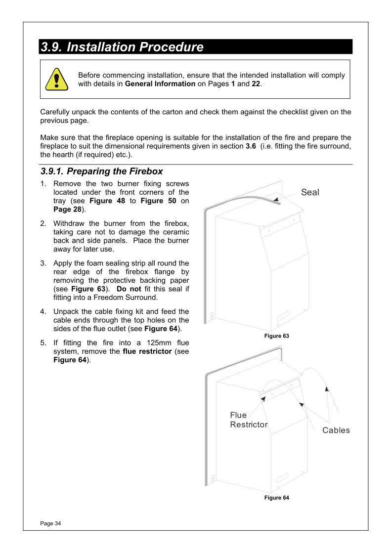
3.9.1. Preparing the Firebox 1. Remove the two burner fixing screws
located under the front corners of the tray (see Figure 48 to Figure 50 on Page 28).
2. Withdraw the burner from the firebox, taking care not to damage the ceramic back and side panels. Place the burner away for later use.
3. Apply the foam sealing strip all round the rear edge of the firebox flange by removing the protective backing paper (see Figure 63). Do not fit this seal if fitting into a Freedom Surround.
4. Unpack the cable fixing kit and feed the cable ends through the top holes on the sides of the flue outlet (see Figure 64).
5. If fitting the fire into a 125mm flue system, remove the flue restrictor (see Figure 64).
Seal
Figure 63
Cables
FlueRestrictor
Figure 64
Page 35
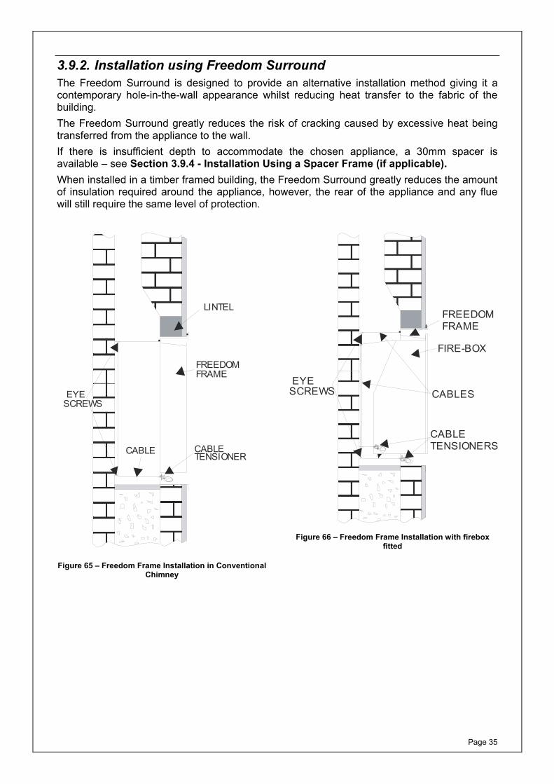
3.9.2. Installation using Freedom SurroundThe Freedom Surround is designed to provide an alternative installation method giving it a contemporary hole-in-the-wall appearance whilst reducing heat transfer to the fabric of the building. The Freedom Surround greatly reduces the risk of cracking caused by excessive heat being transferred from the appliance to the wall. If there is insufficient depth to accommodate the chosen appliance, a 30mm spacer is available – see Section 3.9.4 - Installation Using a Spacer Frame (if applicable). When installed in a timber framed building, the Freedom Surround greatly reduces the amount of insulation required around the appliance, however, the rear of the appliance and any flue will still require the same level of protection.
CABLE CABLETENSIONER
FREEDOMFRAME
LINTEL
EYESCREWS
Figure 65 – Freedom Frame Installation in Conventional Chimney
CABLETENSIONERS
FREEDOMFRAME
CABLES
FIRE-BOX
EYESCREWS
Figure 66 – Freedom Frame Installation with firebox fitted
Page 36
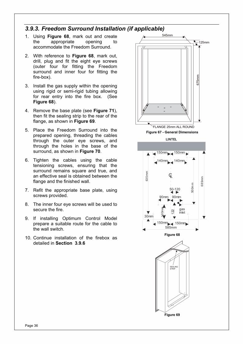
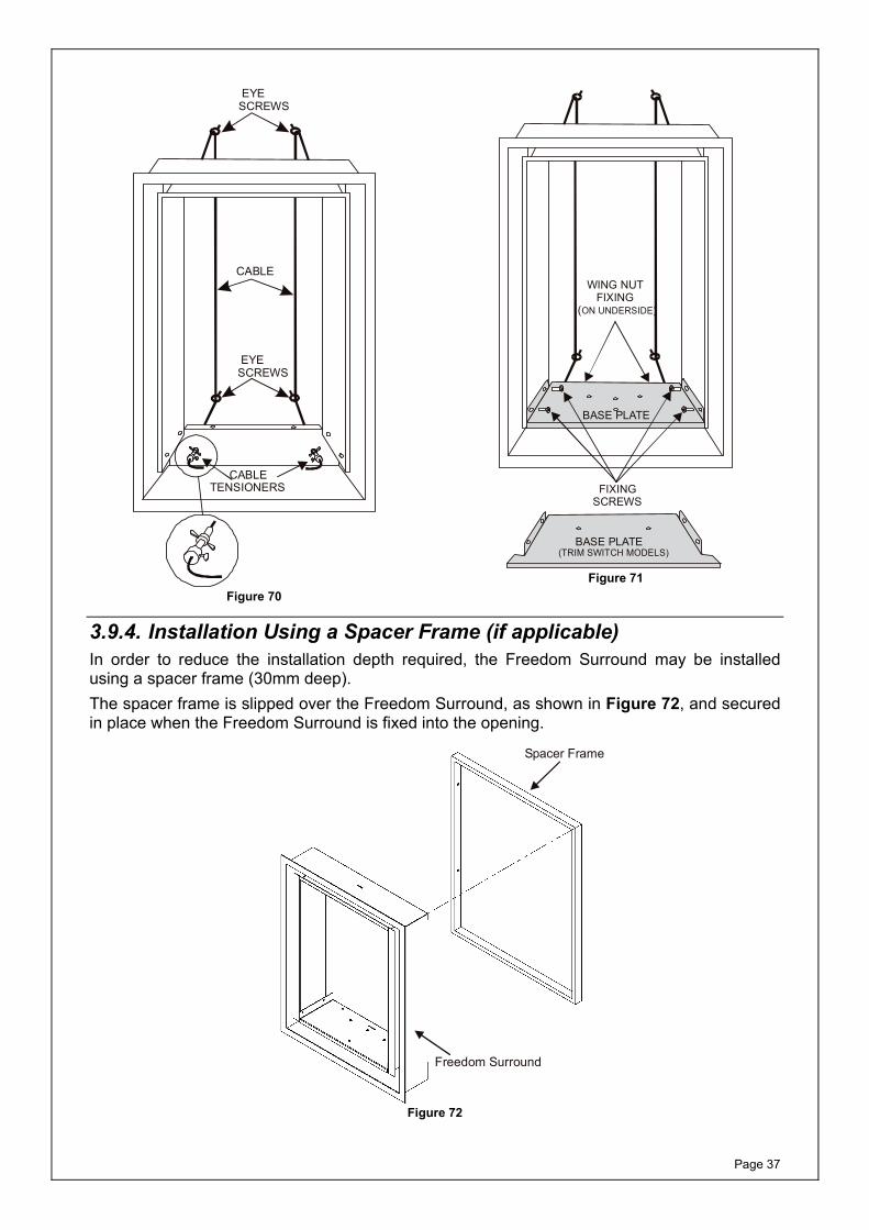
3.9.3. Freedom Surround Installation (if applicable)1. Using Figure 68, mark out and create
the appropriate opening to accommodate the Freedom Surround.
2. With reference to Figure 68, mark out, drill, plug and fit the eight eye screws (outer four for fitting the Freedom surround and inner four for fitting the fire-box).
3. Install the gas supply within the opening using rigid or semi-rigid tubing allowing for rear entry into the fire box. (See Figure 68).
4. Remove the base plate (see Figure 71), then fit the sealing strip to the rear of the flange, as shown in Figure 69.
5. Place the Freedom Surround into the prepared opening, threading the cables through the outer eye screws, and through the holes in the base of the surround, as shown in Figure 70.
6. Tighten the cables using the cable tensioning screws, ensuring that the surround remains square and true, and an effective seal is obtained between the flange and the finished wall.
7. Refit the appropriate base plate, using screws provided.
8. The inner four eye screws will be used to secure the fire.
9. If installing Optimum Control Model prepare a suitable route for the cable to the wall switch.
10. Continue installation of the firebox as detailed in Section 3.9.6
FLANGE 25mm ALL ROUND
125mm
675m
m
545mm
Figure 67 - General Dimensions
LINTEL
150mm 150mm
30mm
685m
m
500m
m
635
mm
150mm 150mm
90mm 90mm
10
0mm
140mm 140mm
CL
585mm
gasinlet12
2
50-120
Figure 68
SEALINGSTRIP
Figure 69
Page 37
EYESCREWS
CABLE
CABLETENSIONERS
EYESCREWS
Figure 70
BASE PLATE
FIXINGSCREWS
WING NUT FIXING(ON UNDERSIDE)
BASE PLATE(TRIM SWITCH MODELS)
Figure 71
3.9.4. Installation Using a Spacer Frame (if applicable) In order to reduce the installation depth required, the Freedom Surround may be installed using a spacer frame (30mm deep). The spacer frame is slipped over the Freedom Surround, as shown in Figure 72, and secured in place when the Freedom Surround is fixed into the opening.
Freedom Surround
Spacer Frame
Figure 72

Page 38
3.9.5. Preparing the Fireplace Opening (all models without Freedom Surround)
1. Prepare the fireplace opening in accordance with Sections 3.2 and 3.6.
2. Mark out, drill, plug and fit the four eye screws onto the rear wall of the fireplace opening as shown in Figure 73.
3. Install any fire surround at this stage, if required.
4. Install the gas supply within the opening using rigid or semi-rigid tubing allowing for rear entry into the fire box (See Figure 73).
5. If installing Optimum Control Model prepare a suitable route for the cable to the wall switch.
150 150
90
530
52
50-120
Centre Line
90
30
eye-screws
Figure 73
Page 39
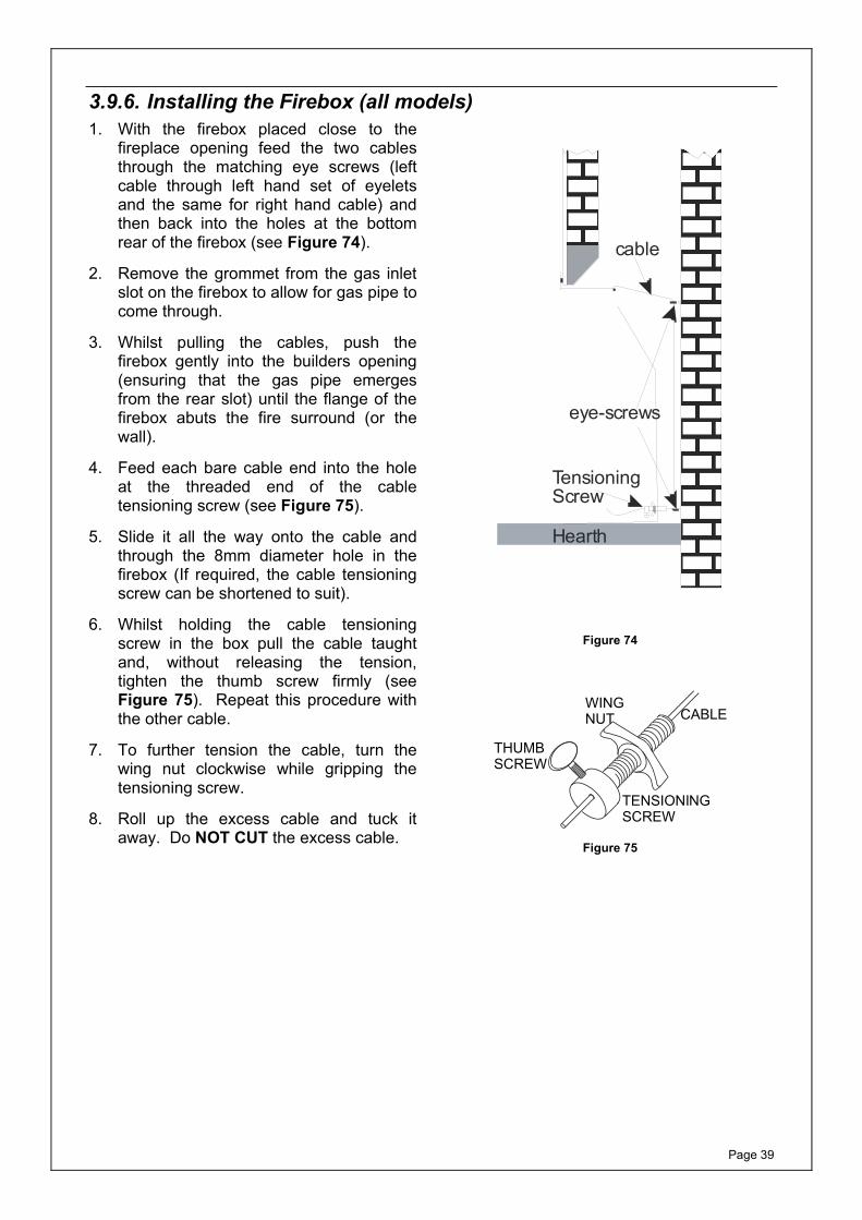
3.9.6. Installing the Firebox (all models) 1. With the firebox placed close to the
fireplace opening feed the two cables through the matching eye screws (left cable through left hand set of eyelets and the same for right hand cable) and then back into the holes at the bottom rear of the firebox (see Figure 74).
2. Remove the grommet from the gas inlet slot on the firebox to allow for gas pipe to come through.
3. Whilst pulling the cables, push the firebox gently into the builders opening (ensuring that the gas pipe emerges from the rear slot) until the flange of the firebox abuts the fire surround (or the wall).
4. Feed each bare cable end into the hole at the threaded end of the cable tensioning screw (see Figure 75).
5. Slide it all the way onto the cable and through the 8mm diameter hole in the firebox (If required, the cable tensioning screw can be shortened to suit).
6. Whilst holding the cable tensioning screw in the box pull the cable taught and, without releasing the tension, tighten the thumb screw firmly (see Figure 75). Repeat this procedure with the other cable.
7. To further tension the cable, turn the wing nut clockwise while gripping the tensioning screw.
8. Roll up the excess cable and tuck it away. Do NOT CUT the excess cable.
eye-screws
cable
TensioningScrew
Hearth
Figure 74
WINGNUT
THUMBSCREW
CABLE
TENSIONINGSCREW
Figure 75
Page 40
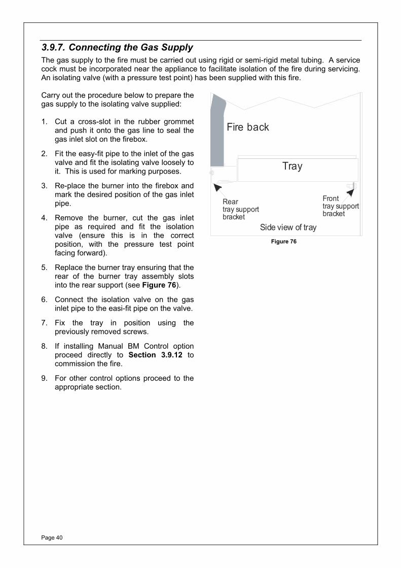
3.9.7. Connecting the Gas Supply The gas supply to the fire must be carried out using rigid or semi-rigid metal tubing. A service cock must be incorporated near the appliance to facilitate isolation of the fire during servicing. An isolating valve (with a pressure test point) has been supplied with this fire. Carry out the procedure below to prepare the gas supply to the isolating valve supplied: 1. Cut a cross-slot in the rubber grommet
and push it onto the gas line to seal the gas inlet slot on the firebox.
2. Fit the easy-fit pipe to the inlet of the gas valve and fit the isolating valve loosely to it. This is used for marking purposes.
3. Re-place the burner into the firebox and mark the desired position of the gas inlet pipe.
4. Remove the burner, cut the gas inlet pipe as required and fit the isolation valve (ensure this is in the correct position, with the pressure test point facing forward).
5. Replace the burner tray ensuring that the rear of the burner tray assembly slots into the rear support (see Figure 76).
6. Connect the isolation valve on the gas inlet pipe to the easi-fit pipe on the valve.
7. Fix the tray in position using the previously removed screws.
8. If installing Manual BM Control option proceed directly to Section 3.9.12 to commission the fire.
9. For other control options proceed to the appropriate section.
Rear tray supportbracket
Tray
Fire back
Front tray supportbracket
Side view of trayFigure 76
Page 41
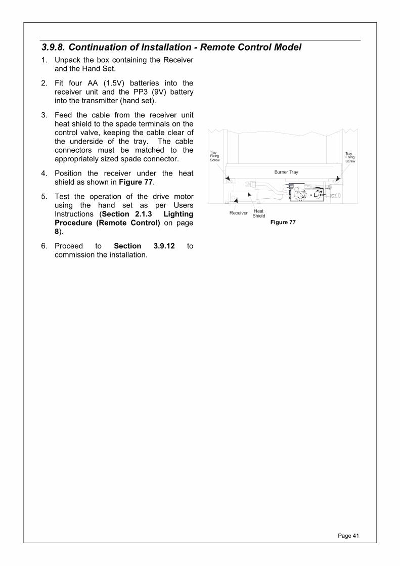
3.9.8. Continuation of Installation - Remote Control Model 1. Unpack the box containing the Receiver
and the Hand Set.
2. Fit four AA (1.5V) batteries into the receiver unit and the PP3 (9V) battery into the transmitter (hand set).
3. Feed the cable from the receiver unit heat shield to the spade terminals on the control valve, keeping the cable clear of the underside of the tray. The cable connectors must be matched to the appropriately sized spade connector.
4. Position the receiver under the heat shield as shown in Figure 77.
5. Test the operation of the drive motor using the hand set as per Users Instructions (Section 2.1.3 Lighting Procedure (Remote Control) on page 8).
6. Proceed to Section 3.9.12 to commission the installation.
Heat ShieldReceiver
Burner Tray
TrayFixingScrew
TrayFixingScrew
Figure 77
Page 42
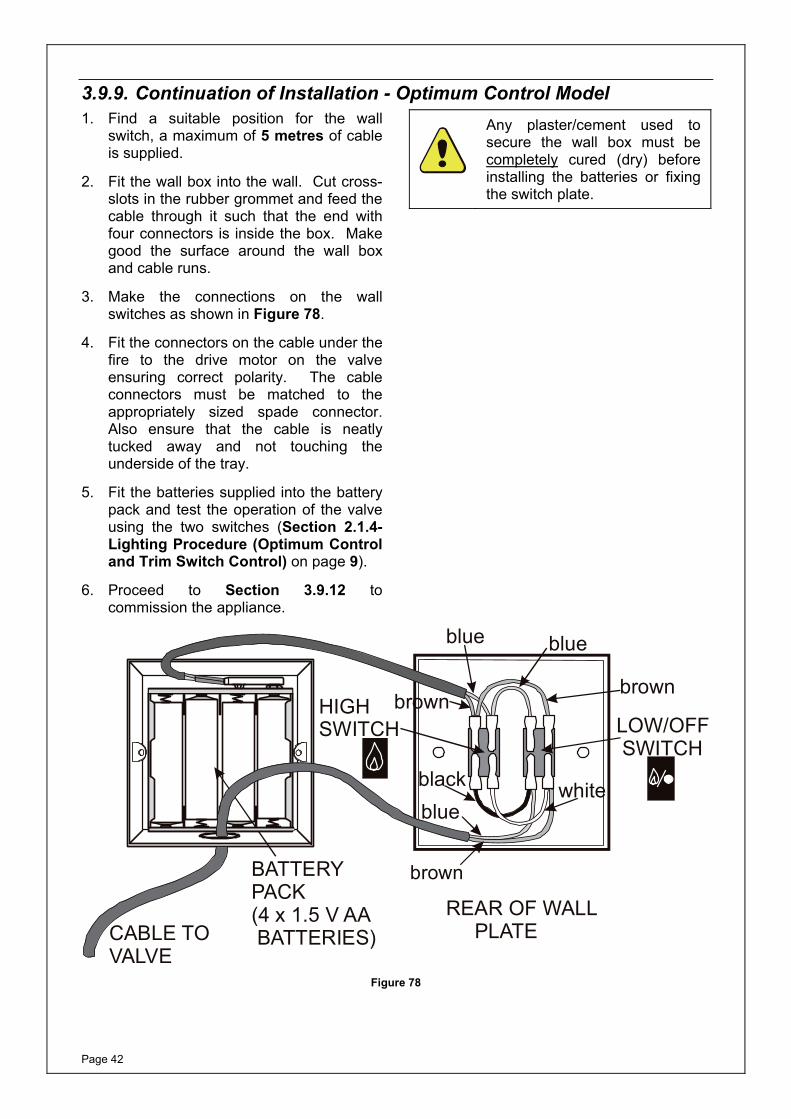
3.9.9. Continuation of Installation - Optimum Control Model 1. Find a suitable position for the wall
switch, a maximum of 5 metres of cable is supplied.
2. Fit the wall box into the wall. Cut cross-slots in the rubber grommet and feed the cable through it such that the end with four connectors is inside the box. Make good the surface around the wall box and cable runs.
3. Make the connections on the wall switches as shown in Figure 78.
4. Fit the connectors on the cable under the fire to the drive motor on the valve ensuring correct polarity. The cable connectors must be matched to the appropriately sized spade connector. Also ensure that the cable is neatly tucked away and not touching the underside of the tray.
5. Fit the batteries supplied into the battery pack and test the operation of the valve using the two switches (Section 2.1.4- Lighting Procedure (Optimum Control and Trim Switch Control) on page 9).
6. Proceed to Section 3.9.12 to commission the appliance.
Any plaster/cement used to secure the wall box must be completely cured (dry) before installing the batteries or fixing the switch plate.
REAR OF WALL PLATECABLE TO
VALVE
BATTERYPACK(4 x 1.5 V AA BATTERIES)
LOW/OFF SWITCH
HIGHSWITCH
brownbrown
brown
blueblue
bluewhiteblack
Figure 78
Page 43
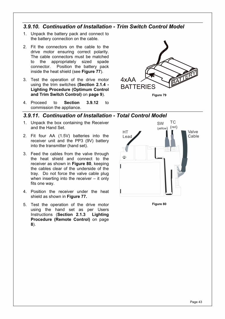
3.9.10. Continuation of Installation - Trim Switch Control Model1. Unpack the battery pack and connect to
the battery connection on the cable.
2. Fit the connectors on the cable to the drive motor ensuring correct polarity. The cable connectors must be matched to the appropriately sized spade connector. Position the battery pack inside the heat shield (see Figure 77).
3. Test the operation of the drive motor using the trim switches (Section 2.1.4 - Lighting Procedure (Optimum Control and Trim Switch Control) on page 9).
4. Proceed to Section 3.9.12 to commission the appliance.
4xAABATTERIES
Figure 79
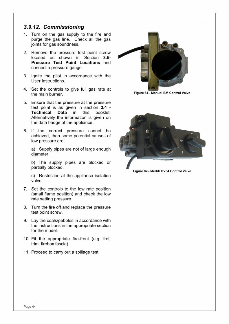
3.9.11. Continuation of Installation - Total Control Model 1. Unpack the box containing the Receiver
and the Hand Set.
2. Fit four AA (1.5V) batteries into the receiver unit and the PP3 (9V) battery into the transmitter (hand set).
3. Feed the cables from the valve through the heat shield and connect to the receiver as shown in Figure 80, keeping the cables clear of the underside of the tray. Do not force the valve cable plug when inserting into the receiver – it only fits one way.
4. Position the receiver under the heat shield as shown in Figure 77.
5. Test the operation of the drive motor using the hand set as per Users Instructions (Section 2.1.3 Lighting Procedure (Remote Control) on page 8).
HTLead
SW)(yellow
TC( )red
ValveCable
Figure 80
Page 44
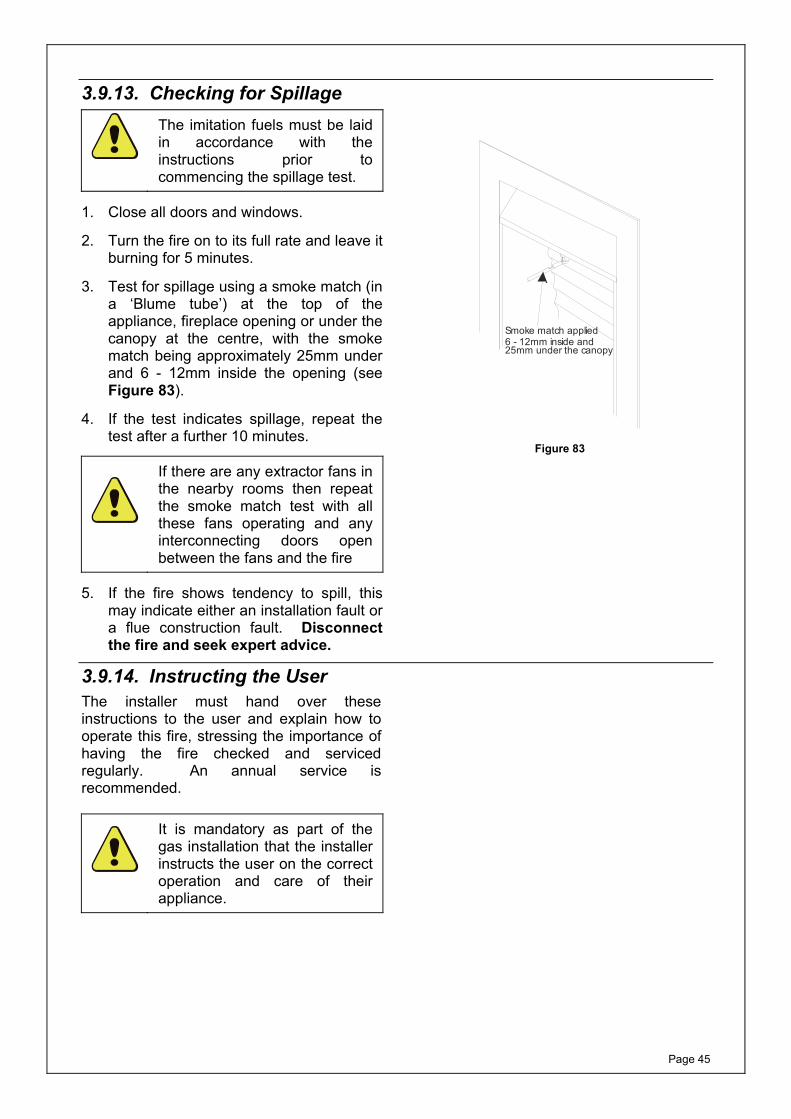
3.9.12. Commissioning 1. Turn on the gas supply to the fire and
purge the gas line. Check all the gas joints for gas soundness.
2. Remove the pressure test point screw located as shown in Section 3.5- Pressure Test Point Locations and connect a pressure gauge.
3. Ignite the pilot in accordance with the User Instructions.
4. Set the controls to give full gas rate at the main burner.
5. Ensure that the pressure at the pressure test point is as given in section 3.4 - Technical Data in this booklet. Alternatively the information is given on the data badge of the appliance.
6. If the correct pressure cannot be achieved, then some potential causes of low pressure are:
a) Supply pipes are not of large enough diameter.
b) The supply pipes are blocked or partially blocked.
c) Restriction at the appliance isolation valve.
7. Set the controls to the low rate position (small flame position) and check the low rate setting pressure.
8. Turn the fire off and replace the pressure test point screw.
9. Lay the coals/pebbles in accordance with the instructions in the appropriate section for the model.
10. Fit the appropriate fire-front (e.g. fret, trim, firebox fascia).
11. Proceed to carry out a spillage test.
Figure 81– Manual BM Control Valve
Figure 82– Mertik GV34 Control Valve
Page 45
3.9.13. Checking for Spillage
The imitation fuels must be laid in accordance with the instructions prior to commencing the spillage test.
1. Close all doors and windows.
2. Turn the fire on to its full rate and leave it burning for 5 minutes.
3. Test for spillage using a smoke match (in a ‘Blume tube’) at the top of the appliance, fireplace opening or under the canopy at the centre, with the smoke match being approximately 25mm under and 6 - 12mm inside the opening (see Figure 83).
4. If the test indicates spillage, repeat the test after a further 10 minutes.
If there are any extractor fans in the nearby rooms then repeat the smoke match test with all these fans operating and any interconnecting doors open between the fans and the fire
5. If the fire shows tendency to spill, this may indicate either an installation fault or a flue construction fault. Disconnect the fire and seek expert advice.
Smoke match applied6 - 12mm inside and25mm under the canopy
Figure 83
3.9.14. Instructing the UserThe installer must hand over these instructions to the user and explain how to operate this fire, stressing the importance of having the fire checked and serviced regularly. An annual service is recommended.
It is mandatory as part of the gas installation that the installer instructs the user on the correct operation and care of their appliance.

Page 46
This page is intentionally left blank
Page 47
4. SERVICING INSTRUCTIONS
4.1. General Requirements All repairs and servicing must be carried out by a qualified registered gas installer (e.g. member of Gas Safe in GB) in accordance with the current Gas Safety (Installation and Use) Regulations and these instructions. Before any servicing is carried out ensure that the gas and electrical supply (where applicable) have been isolated. After any servicing or replacement of any parts, the appliance should be re-commissioned.
4.2. Servicing Instructions As part of the appliance service, the flue and fireplace opening should be checked for soundness and any debris removed. For this the firebox will need removal from the fireplace opening.
Refer to the section:
2.8.1 – Cleaning the Fire-bed on Page 22
and section:
2.8.2 – Cleaning the Pilot on Page 23.
On completion of the servicing, a spillage test must be carried out.
WARNING: ODS Pilot Assembly Under no circumstances should the pilot assembly be adjusted or put out of action by the installer. If the pilot needs replacing, only the approved part (available from your supplier or Burley Magiglo.) should be fitted. Note: if any part of the pilot assembly becomes faulty the complete assembly will need replacing.
Page 48
4.3. Replacing Parts For any spare parts that are required, please contact either your supplier or the manufacturer directly. You will either need the serial number or: a) model name; b) the gas type; c) the imitation fuel type; d) the type of control. Only approved parts should be used. 4.3.1. Pilot Assembly Replacement
NOTE: If any part of the pilot assembly becomes faulty then the whole pilot assembly will need changing.
1. Remove the HT lead from the end of the electrode.
2. Cut the cable tie wrap.
3. Using M9 spanner undo the thermocouple connection from behind the control valve
4. Using M10 spanner undo the pilot feed pipe nut at the pilot assembly.
5. Remove the pilot lint guard and undo the pilot assembly securing screws and withdraw the pilot assembly.
6. Refit in reverse order ensuring that the lint guard is fitted.
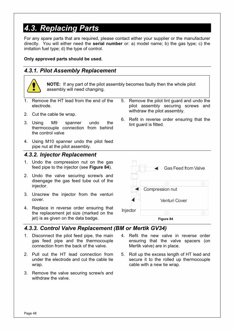
4.3.2. Injector Replacement1. Undo the compression nut on the gas
feed pipe to the injector (see Figure 84).
2. Undo the valve securing screw/s and disengage the gas feed tube out of the injector.
3. Unscrew the injector from the venturi cover.
4. Replace in reverse order ensuring that the replacement jet size (marked on the jet) is as given on the data badge.
Venturi Cover
Injector
Compression nut
Gas Feed from Valve
Figure 84
4.3.3. Control Valve Replacement (BM or Mertik GV34)1. Disconnect the pilot feed pipe, the main
gas feed pipe and the thermocouple connection from the back of the valve.
2. Pull out the HT lead connection from under the electrode and cut the cable tie wrap.
3. Remove the valve securing screw/s and withdraw the valve.
4. Refit the new valve in reverse order ensuring that the valve spacers (on Mertik valve) are in place.
5. Roll up the excess length of HT lead and secure it to the rolled up thermocouple cable with a new tie wrap.
Page 49
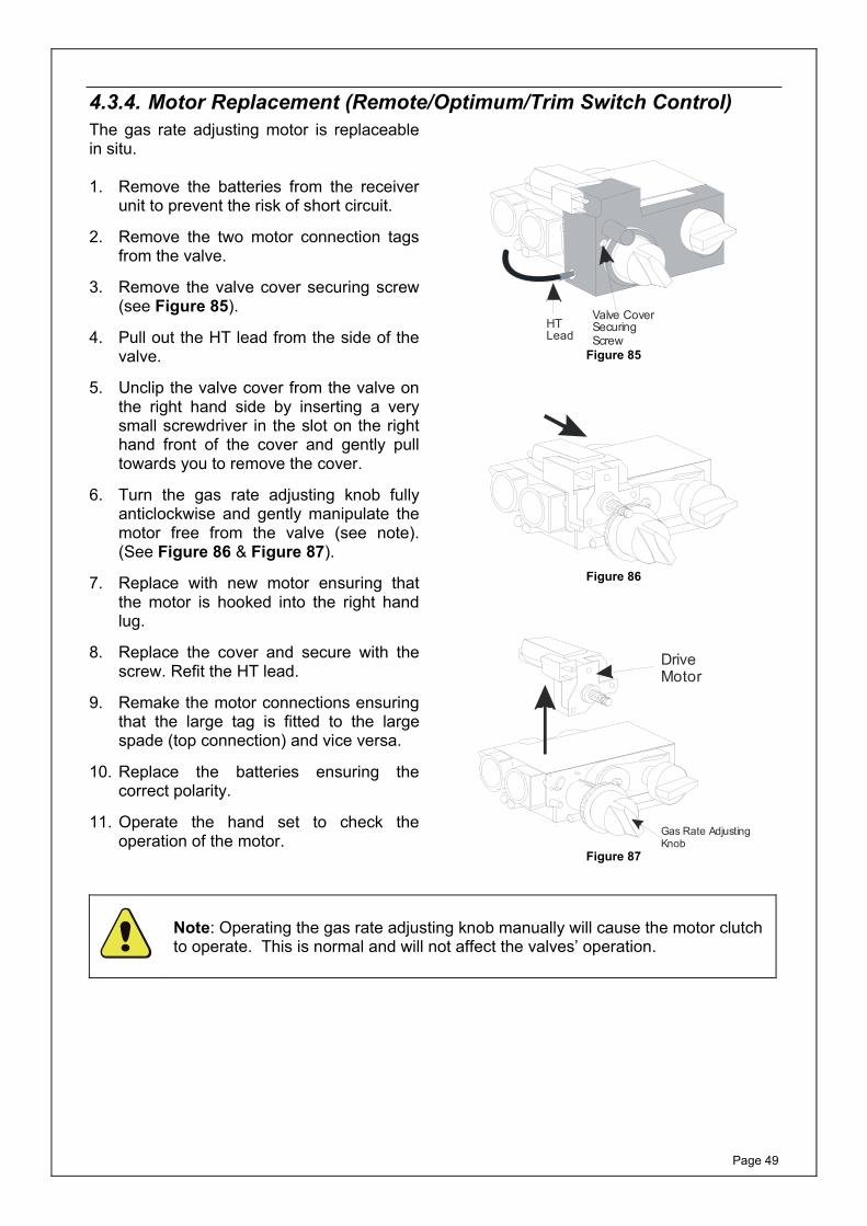
4.3.4. Motor Replacement (Remote/Optimum/Trim Switch Control)The gas rate adjusting motor is replaceable in situ. 1. Remove the batteries from the receiver
unit to prevent the risk of short circuit.
2. Remove the two motor connection tags from the valve.
3. Remove the valve cover securing screw (see Figure 85).
4. Pull out the HT lead from the side of the valve.
5. Unclip the valve cover from the valve on the right hand side by inserting a very small screwdriver in the slot on the right hand front of the cover and gently pull towards you to remove the cover.
6. Turn the gas rate adjusting knob fully anticlockwise and gently manipulate the motor free from the valve (see note). (See Figure 86 & Figure 87).
7. Replace with new motor ensuring that the motor is hooked into the right hand lug.
8. Replace the cover and secure with the screw. Refit the HT lead.
9. Remake the motor connections ensuring that the large tag is fitted to the large spade (top connection) and vice versa.
10. Replace the batteries ensuring the correct polarity.
11. Operate the hand set to check the operation of the motor.
Valve CoverSecuringScrew
HTLead
Figure 85
Figure 86
Gas Rate AdjustingKnob
DriveMotor
Figure 87
Note: Operating the gas rate adjusting knob manually will cause the motor clutch to operate. This is normal and will not affect the valves’ operation.
Page 50
4.3.5. Replacing Mertik GV60 Valve (Total Control)
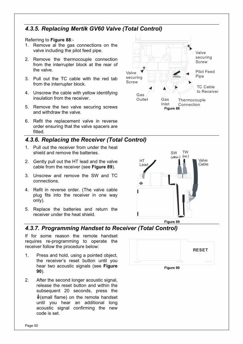
Referring to Figure 88:- 1. Remove al the gas connections on the
valve including the pilot feed pipe.
2. Remove the thermocouple connection from the interrupter block at the rear of the valve.
3. Pull out the TC cable with the red tab from the interrupter block.
4. Unscrew the cable with yellow identifying insulation from the receiver.
5. Remove the two valve securing screws and withdraw the valve.
6. Refit the replacement valve in reverse order ensuring that the valve spacers are fitted.
Pilot FeedPipe
TC Cableto Receiver
ThermocoupleConnection
GasInlet
GasOutlet
ValvesecuringScrew
ValvesecuringScrew
Figure 88
4.3.6. Replacing the Receiver (Total Control) 1. Pull out the receiver from under the heat
shield and remove the batteries.
2. Gently pull out the HT lead and the valve cable from the receiver (see Figure 89).
3. Unscrew and remove the SW and TC connections.
4. Refit in reverse order. (The valve cable plug fits into the receiver in one way only).
5. Replace the batteries and return the receiver under the heat shield.
HTLead
SW)(yellow
TW( )red
ValveCable
Figure 89
4.3.7. Programming Handset to Receiver (Total Control) If for some reason the remote handset requires re-programming to operate the receiver follow the procedure below:
1. Press and hold, using a pointed object, the receiver’s reset button until you hear two acoustic signals (see Figure 90).
2. After the second longer acoustic signal, release the reset button and within the subsequent 20 seconds, press the
(small flame) on the remote handset until you hear an additional long acoustic signal confirming the new code is set.
RESET
Figure 90
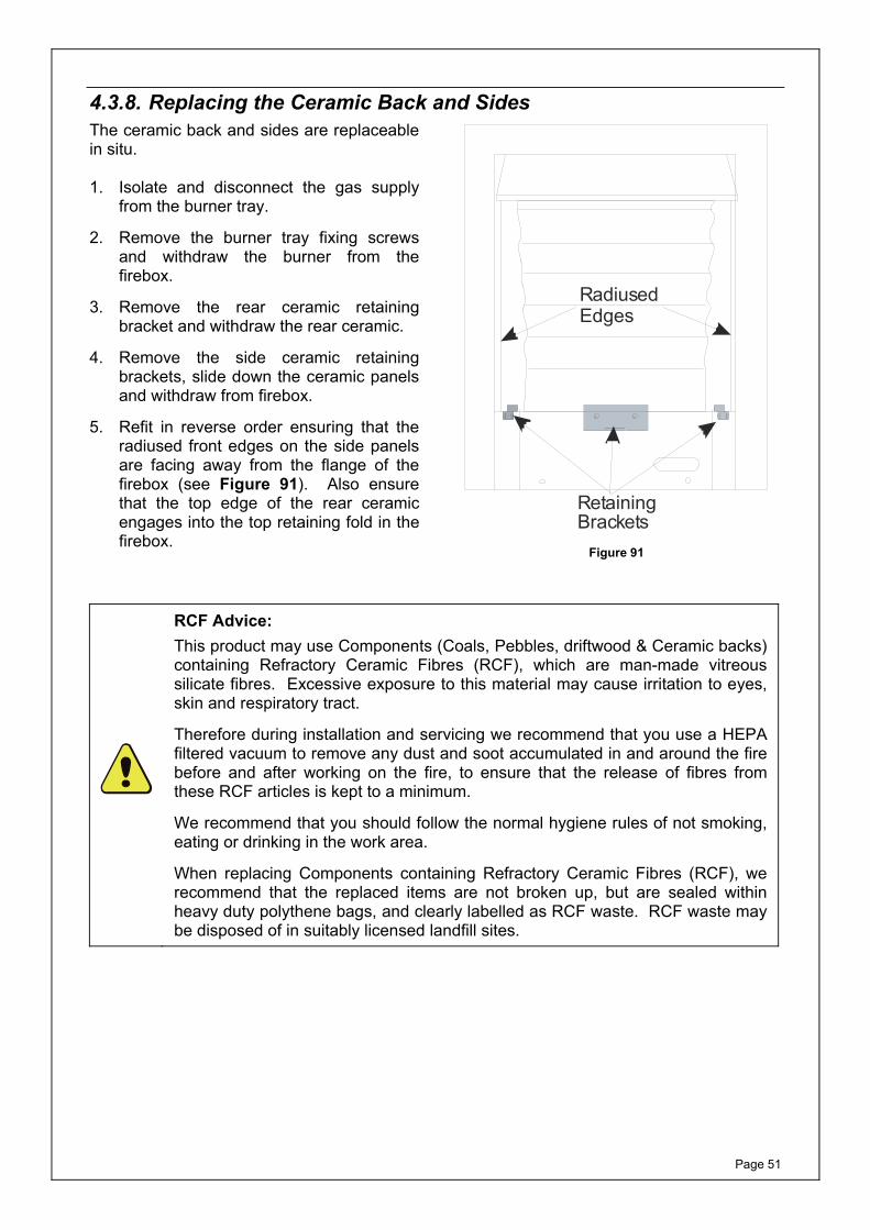
Page 51
4.3.8. Replacing the Ceramic Back and Sides The ceramic back and sides are replaceable in situ. 1. Isolate and disconnect the gas supply
from the burner tray.
2. Remove the burner tray fixing screws and withdraw the burner from the firebox.
3. Remove the rear ceramic retaining bracket and withdraw the rear ceramic.
4. Remove the side ceramic retaining brackets, slide down the ceramic panels and withdraw from firebox.
5. Refit in reverse order ensuring that the radiused front edges on the side panels are facing away from the flange of the firebox (see Figure 91). Also ensure that the top edge of the rear ceramic engages into the top retaining fold in the firebox.
RetainingBrackets
RadiusedEdges
Figure 91
RCF Advice: This product may use Components (Coals, Pebbles, driftwood & Ceramic backs) containing Refractory Ceramic Fibres (RCF), which are man-made vitreous silicate fibres. Excessive exposure to this material may cause irritation to eyes, skin and respiratory tract.
Therefore during installation and servicing we recommend that you use a HEPA filtered vacuum to remove any dust and soot accumulated in and around the fire before and after working on the fire, to ensure that the release of fibres from these RCF articles is kept to a minimum.
We recommend that you should follow the normal hygiene rules of not smoking, eating or drinking in the work area.
When replacing Components containing Refractory Ceramic Fibres (RCF), we recommend that the replaced items are not broken up, but are sealed within heavy duty polythene bags, and clearly labelled as RCF waste. RCF waste may be disposed of in suitably licensed landfill sites.
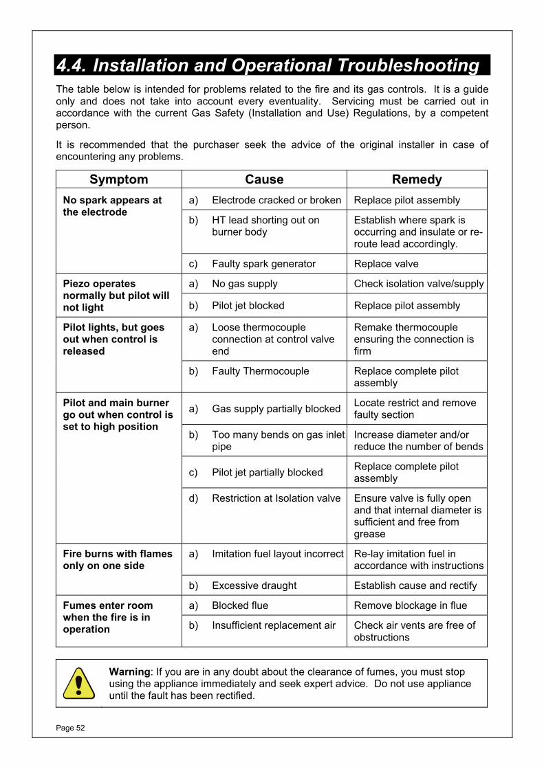
Page 52
4.4. Installation and Operational Troubleshooting The table below is intended for problems related to the fire and its gas controls. It is a guide only and does not take into account every eventuality. Servicing must be carried out in accordance with the current Gas Safety (Installation and Use) Regulations, by a competent person.
It is recommended that the purchaser seek the advice of the original installer in case of encountering any problems.
Symptom Cause Remedy No spark appears at the electrode
a) Electrode cracked or broken Replace pilot assembly
b) HT lead shorting out on burner body
Establish where spark is occurring and insulate or re-route lead accordingly.
c) Faulty spark generator Replace valve
Piezo operates normally but pilot will not light
a) No gas supply Check isolation valve/supply
b) Pilot jet blocked Replace pilot assembly
Pilot lights, but goes out when control is released
a) Loose thermocouple connection at control valve end
Remake thermocouple ensuring the connection is firm
b) Faulty Thermocouple Replace complete pilot assembly
Pilot and main burner go out when control is set to high position
a) Gas supply partially blocked Locate restrict and remove faulty section
b) Too many bends on gas inlet pipe
Increase diameter and/or reduce the number of bends
c) Pilot jet partially blocked Replace complete pilot assembly
d) Restriction at Isolation valve Ensure valve is fully open and that internal diameter is sufficient and free from grease
Fire burns with flames only on one side
a) Imitation fuel layout incorrect Re-lay imitation fuel in accordance with instructions
b) Excessive draught Establish cause and rectify
Fumes enter room when the fire is in operation
a) Blocked flue Remove blockage in flue
b) Insufficient replacement air Check air vents are free of obstructions
Warning: If you are in any doubt about the clearance of fumes, you must stop using the appliance immediately and seek expert advice. Do not use appliance until the fault has been rectified.
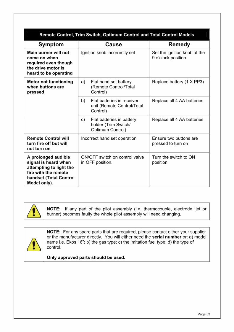
Page 53
Remote Control, Trim Switch, Optimum Control and Total Control Models
Symptom Cause Remedy Main burner will not come on when required even though the drive motor is heard to be operating
Ignition knob incorrectly set Set the ignition knob at the 9 o’clock position.
Motor not functioning when buttons are pressed
a) Flat hand set battery (Remote Control/Total Control)
Replace battery (1 X PP3)
b) Flat batteries in receiver unit (Remote Control/Total Control)
Replace all 4 AA batteries
c) Flat batteries in battery holder (Trim Switch/ Optimum Control)
Replace all 4 AA batteries
Remote Control will turn fire off but will not turn on
Incorrect hand set operation Ensure two buttons are pressed to turn on
A prolonged audible signal is heard when attempting to light the fire with the remote handset (Total Control Model only).
ON/OFF switch on control valve in OFF position.
Turn the switch to ON position
NOTE: If any part of the pilot assembly (i.e. thermocouple, electrode, jet or burner) becomes faulty the whole pilot assembly will need changing.
NOTE: For any spare parts that are required, please contact either your supplier or the manufacturer directly. You will either need the serial number or: a) model name i.e. Ekos 16”; b) the gas type; c) the imitation fuel type; d) the type of control. Only approved parts should be used.

Page 54
This page is intentionally left blank

Page 55
This page is intentionally left blank

MF444.4
Magiglo fires are protected by UK patents 2193802, 2240620 and 2256920
Other Patents Pending
Magiglo is a registered trademark of Burley Appliances Ltd.
Burley Magiglo, Lands End Way,
Oakham; Rutland,LE15 6RB
Tel: 01572 725570 Fax: 01572 724390 www.magiglo.co.uk Email: [email protected]