Embed Size (px)
Citation preview
高速串行测试方案介绍 泰克华东区技术支持工程师 余洋

2013/11/5 2
High-Speed Serial Data Test Solutions
Design Verification Compliance Test
Interconnect Test
Interconnect Tx +
-
+
-
+
-
+
-
Rx
Transmitter Testing
System Integration Digital Validation & Debug
Receiver Test
Margin Testing
Compliance Test
Real-time Scopes
Sampling Scopes
Arbitrary Waveform Generator
Logic Analyzers
Compliance Test Software
Probing Fixtures
GbE MHL …
Agenda
Storage
PCIe
USB3
DDR
ThunderBolt
HDMI
MHL
MIPI
10GBase-T
SFP+
10G-KR
June 5, 2012 Tektronix Confidential 3
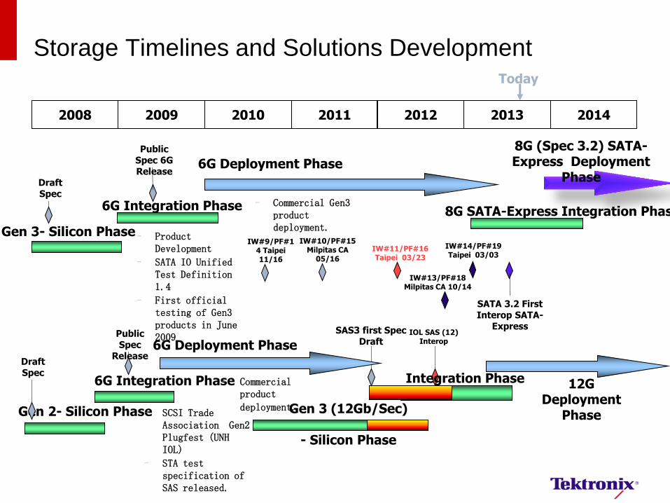
Storage Timelines and Solutions Development Today
2008 2009 2010 2011
Gen 3- Silicon Phase
6G Integration Phase
– Product Development
– SATA IO Unified Test Definition 1.4
– First official testing of Gen3 products in June 2009
Draft Spec
6G Deployment Phase
Public Spec 6G Release
– Commercial Gen3 product deployment.
Gen 2- Silicon Phase
6G Integration Phase
Draft Spec
6G Deployment Phase Public Spec
Release
– Commercial product
deployment. Gen 3 (12Gb/Sec)
- Silicon Phase
– SCSI Trade Association Gen2 Plugfest (UNH IOL)
– STA test specification of SAS released.
2012
IW#9/PF#14 Taipei 11/16
SAS3 first Spec Draft
IW#10/PF#15 Milpitas CA
05/16
IW#11/PF#16 Taipei 03/23
2013 2014
IW#13/PF#18 Milpitas CA 10/14
IW#14/PF#19 Taipei 03/03
8G SATA-Express Integration Phase
SATA 3.2 First Interop SATA-
Express
8G (Spec 3.2) SATA-Express Deployment
Phase
IOL SAS (12) Interop
Integration Phase 12G Deployment
Phase
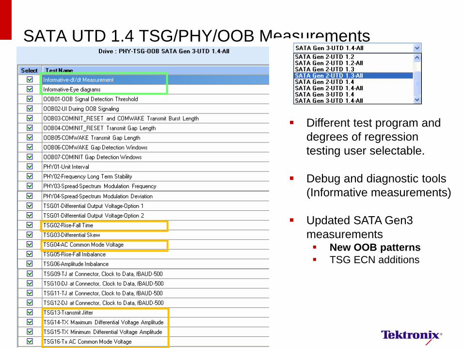
SATA UTD 1.4 TSG/PHY/OOB Measurements PHY TRANSMITTED SIGNAL
GROUP REQUIREMENTS (TSG 1-12)
Different test program and
degrees of regression
testing user selectable.
Debug and diagnostic tools
(Informative measurements)
Updated SATA Gen3
measurements New OOB patterns
TSG ECN additions
SATA/SAS Physical Layer Validation 6
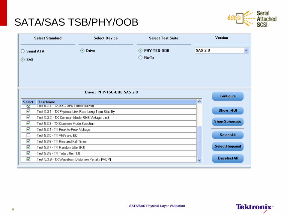
SATA/SAS TSB/PHY/OOB
6
June 5, 2012 Tektronix Confidential 7
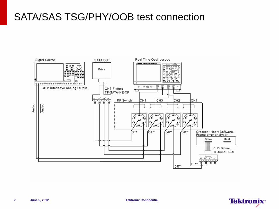
SATA/SAS TSG/PHY/OOB test connection
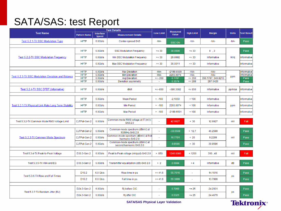
SATA/SAS Physical Layer Validation
SATA/SAS: test Report
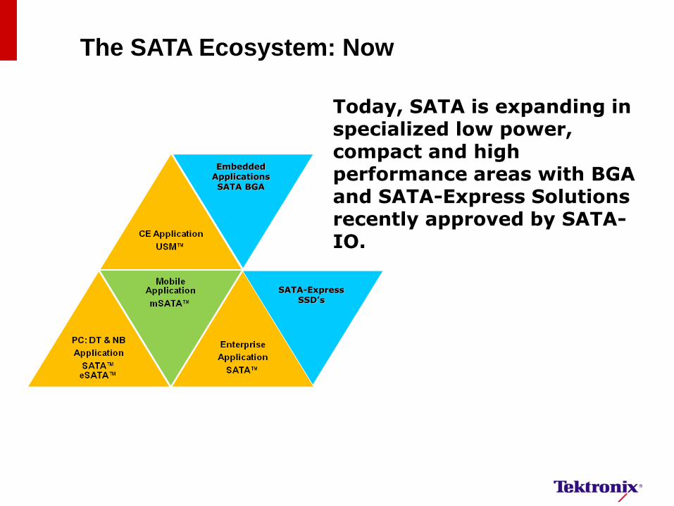
Embedded Applications SATA BGA
Today, SATA is expanding in specialized low power, compact and high performance areas with BGA and SATA-Express Solutions recently approved by SATA-IO.
The SATA Ecosystem: Now
SATA-Express SSD’s

PCB
PCIe Conn.
PCIe/SATA Conn.
PCB
Accept only a x2
PCIe, or a
x1 PCIe cable
Keys that reject the SATA cables
Accept a x2 PCIe, or a x1 PCIe, or two
SATA cables
Desktop Connector Concept
Enabling the New SATA Express Ecosystem
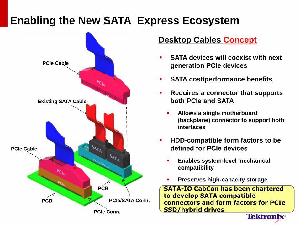
Desktop Cables Concept
PCIe Cable
Existing SATA Cable
PCIe Cable
PCB
PCB PCIe/SATA Conn.
PCIe Conn.
SATA devices will coexist with next
generation PCIe devices
SATA cost/performance benefits
Requires a connector that supports
both PCIe and SATA
Allows a single motherboard
(backplane) connector to support both
interfaces
HDD-compatible form factors to be
defined for PCIe devices
Enables system-level mechanical
compatibility
Preserves high-capacity storage
SATA-IO CabCon has been chartered to develop SATA compatible connectors and form factors for PCIe SSD/hybrid drives
Enabling the New SATA Express Ecosystem
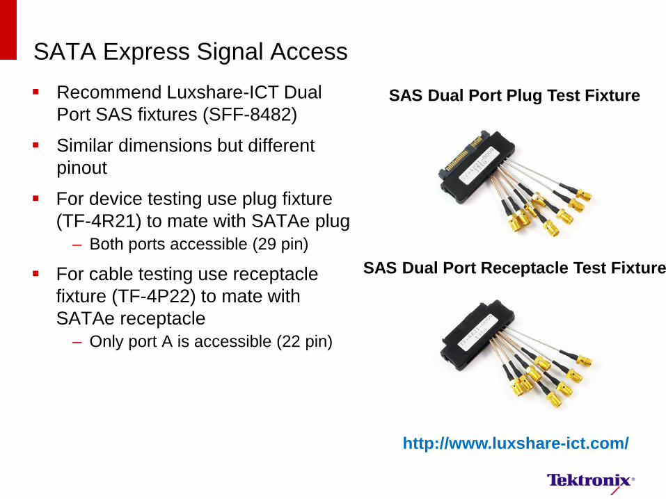
SATA Express Signal Access
Recommend Luxshare-ICT Dual
Port SAS fixtures (SFF-8482)
Similar dimensions but different
pinout
For device testing use plug fixture
(TF-4R21) to mate with SATAe plug
– Both ports accessible (29 pin)
For cable testing use receptacle
fixture (TF-4P22) to mate with
SATAe receptacle
– Only port A is accessible (22 pin)
SAS Dual Port Plug Test Fixture
SAS Dual Port Receptacle Test Fixture
http://www.luxshare-ict.com/
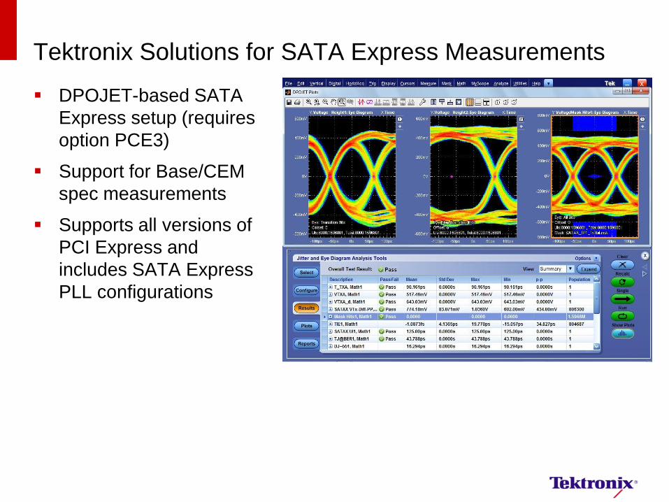
Tektronix Solutions for SATA Express Measurements
DPOJET-based SATA
Express setup (requires
option PCE3)
Support for Base/CEM
spec measurements
Supports all versions of
PCI Express and
includes SATA Express
PLL configurations
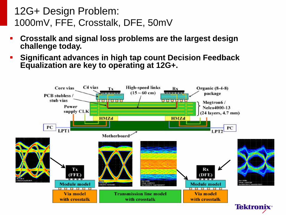
12G+ Design Problem: 1000mV, FFE, Crosstalk, DFE, 50mV
Crosstalk and signal loss problems are the largest design challenge today.
Significant advances in high tap count Decision Feedback Equalization are key to operating at 12G+.
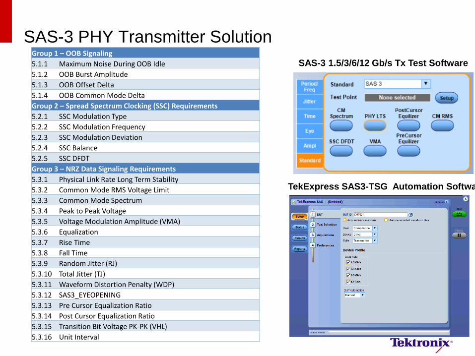
SAS-3 PHY Transmitter Solution
SAS-3 1.5/3/6/12 Gb/s Tx Test Software
TekExpress SAS3-TSG Automation Software
Group 1 – OOB Signaling
5.1.1 Maximum Noise During OOB Idle
5.1.2 OOB Burst Amplitude
5.1.3 OOB Offset Delta
5.1.4 OOB Common Mode Delta
Group 2 – Spread Spectrum Clocking (SSC) Requirements
5.2.1 SSC Modulation Type
5.2.2 SSC Modulation Frequency
5.2.3 SSC Modulation Deviation
5.2.4 SSC Balance
5.2.5 SSC DFDT
Group 3 – NRZ Data Signaling Requirements
5.3.1 Physical Link Rate Long Term Stability
5.3.2 Common Mode RMS Voltage Limit
5.3.3 Common Mode Spectrum
5.3.4 Peak to Peak Voltage
5.3.5 Voltage Modulation Amplitude (VMA)
5.3.6 Equalization
5.3.7 Rise Time
5.3.8 Fall Time
5.3.9 Random Jitter (RJ)
5.3.10 Total Jitter (TJ)
5.3.11 Waveform Distortion Penalty (WDP)
5.3.12 SAS3_EYEOPENING
5.3.13 Pre Cursor Equalization Ratio
5.3.14 Post Cursor Equalization Ratio
5.3.15 Transition Bit Voltage PK-PK (VHL)
5.3.16 Unit Interval
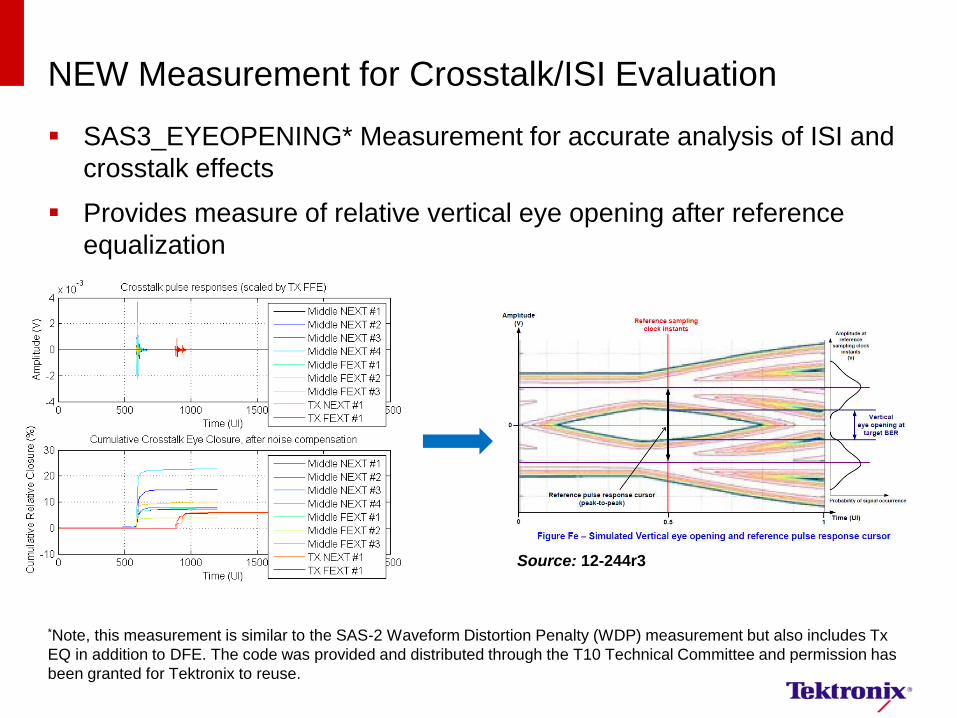
NEW Measurement for Crosstalk/ISI Evaluation
SAS3_EYEOPENING* Measurement for accurate analysis of ISI and
crosstalk effects
Provides measure of relative vertical eye opening after reference
equalization
*Note, this measurement is similar to the SAS-2 Waveform Distortion Penalty (WDP) measurement but also includes Tx
EQ in addition to DFE. The code was provided and distributed through the T10 Technical Committee and permission has
been granted for Tektronix to reuse.
Source: 12-244r3
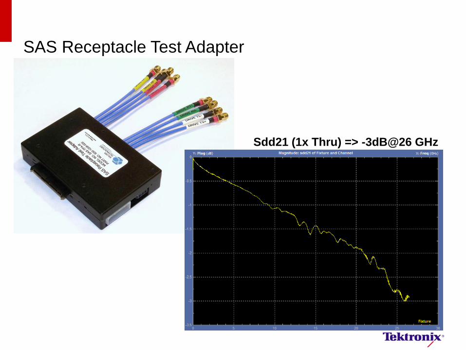
SAS Receptacle Test Adapter
Sdd21 (1x Thru) => -3dB@26 GHz

Test Fixture De-embedding
Why de-embed?
– Tx measurements referenced to
die (ET)
– Improve margin with removal of
fixture effects
S-Parameters acquired from
calibration fixture or model
extraction
Use inverse response to
compensate for loss
Before After
Before
De-Embed
After
De-Embed
Eye
Height 711 mV 770 mV
Rise Time 57 37

Mini-SAS HD Plug Test Adapters
High-Performance Mini-SAS HD Plug Connector Configuration
16 SMAs for High-Speed Testing
8 Position Low-Speed Connector
Color Coded and Imprinted
Markings
(Large Colored = Channel Number)
(Short White = Transmitter Side)
(Short Red = Positive Polarity)
Small Form-Factor Housing (allows for 1x2 4X testing when using left-hand version TPA)
Mini SAS HD 8i
cable plug connector
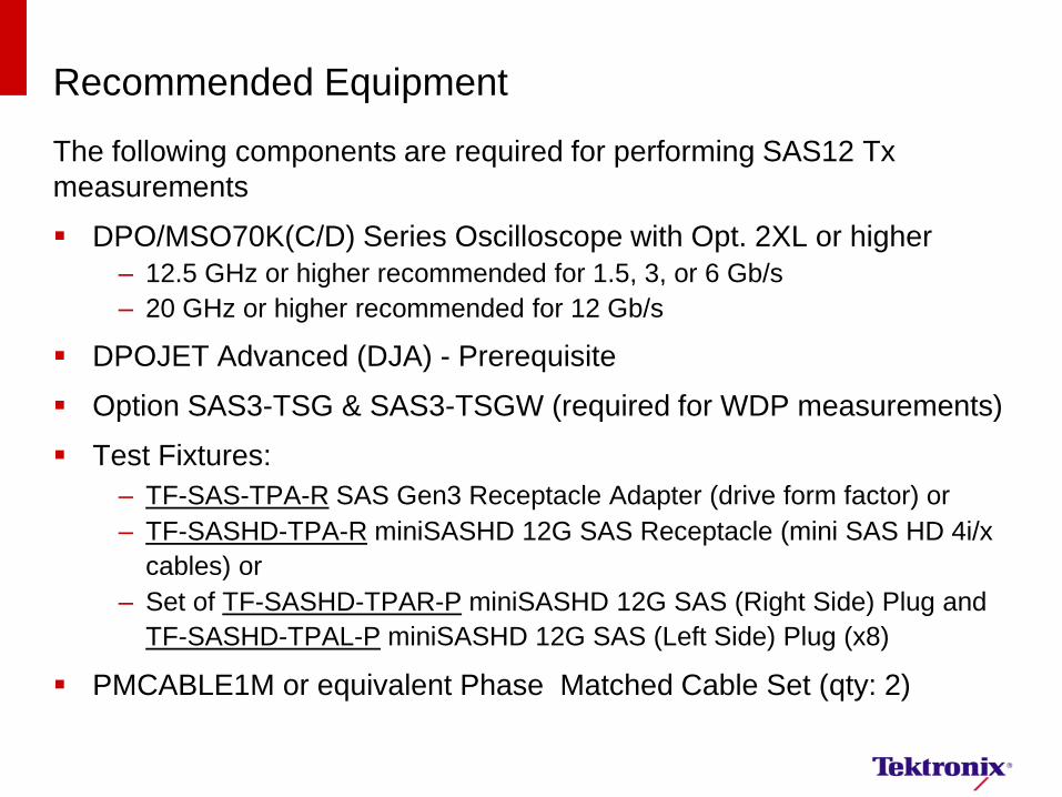
Recommended Equipment
The following components are required for performing SAS12 Tx
measurements
DPO/MSO70K(C/D) Series Oscilloscope with Opt. 2XL or higher
– 12.5 GHz or higher recommended for 1.5, 3, or 6 Gb/s
– 20 GHz or higher recommended for 12 Gb/s
DPOJET Advanced (DJA) - Prerequisite
Option SAS3-TSG & SAS3-TSGW (required for WDP measurements)
Test Fixtures:
– TF-SAS-TPA-R SAS Gen3 Receptacle Adapter (drive form factor) or
– TF-SASHD-TPA-R miniSASHD 12G SAS Receptacle (mini SAS HD 4i/x
cables) or
– Set of TF-SASHD-TPAR-P miniSASHD 12G SAS (Right Side) Plug and
TF-SASHD-TPAL-P miniSASHD 12G SAS (Left Side) Plug (x8)
PMCABLE1M or equivalent Phase Matched Cable Set (qty: 2)
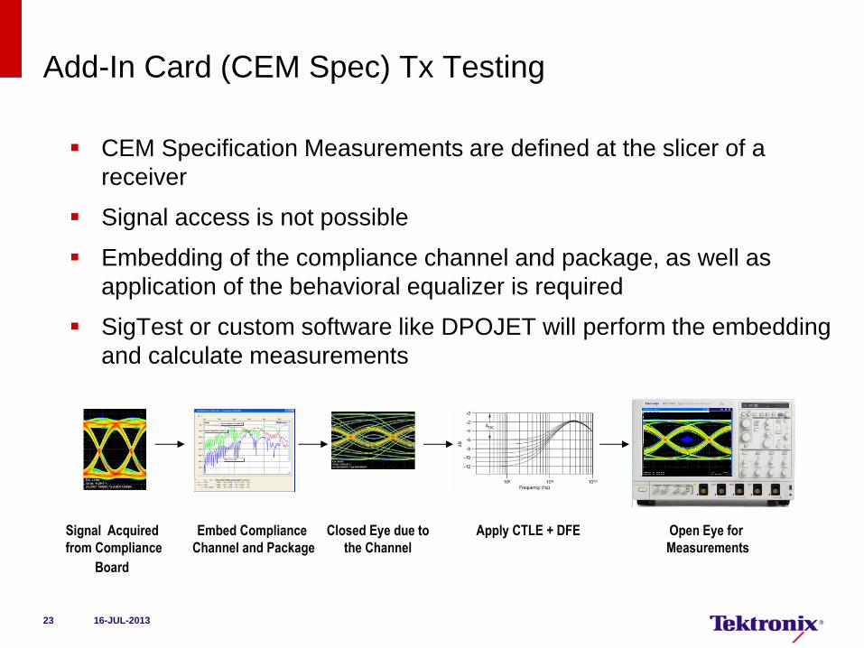
Add-In Card (CEM Spec) Tx Testing
CEM Specification Measurements are defined at the slicer of a
receiver
Signal access is not possible
Embedding of the compliance channel and package, as well as
application of the behavioral equalizer is required
SigTest or custom software like DPOJET will perform the embedding
and calculate measurements
Signal Acquired
from Compliance
Board
Closed Eye due to
the Channel
Apply CTLE + DFE Open Eye for
Measurements
Embed Compliance
Channel and Package
16-JUL-2013 23
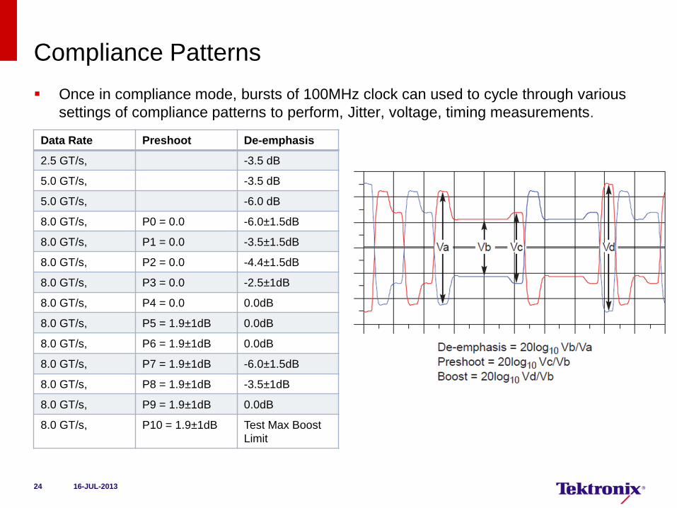
Compliance Patterns
Once in compliance mode, bursts of 100MHz clock can used to cycle through various
settings of compliance patterns to perform, Jitter, voltage, timing measurements.
Data Rate Preshoot De-emphasis
2.5 GT/s, -3.5 dB
5.0 GT/s, -3.5 dB
5.0 GT/s, -6.0 dB
8.0 GT/s, P0 = 0.0 -6.0±1.5dB
8.0 GT/s, P1 = 0.0 -3.5±1.5dB
8.0 GT/s, P2 = 0.0 -4.4±1.5dB
8.0 GT/s, P3 = 0.0 -2.5±1dB
8.0 GT/s, P4 = 0.0 0.0dB
8.0 GT/s, P5 = 1.9±1dB 0.0dB
8.0 GT/s, P6 = 1.9±1dB 0.0dB
8.0 GT/s, P7 = 1.9±1dB -6.0±1.5dB
8.0 GT/s, P8 = 1.9±1dB -3.5±1dB
8.0 GT/s, P9 = 1.9±1dB 0.0dB
8.0 GT/s, P10 = 1.9±1dB Test Max Boost
Limit
16-JUL-2013 24

PCIE Dual-Port TX Measurement Example for System
PCI Express* 3.0
Compliance Data
100 MHz
Reference
Clock
All other lanes
are terminated
with 50 Ohm
load
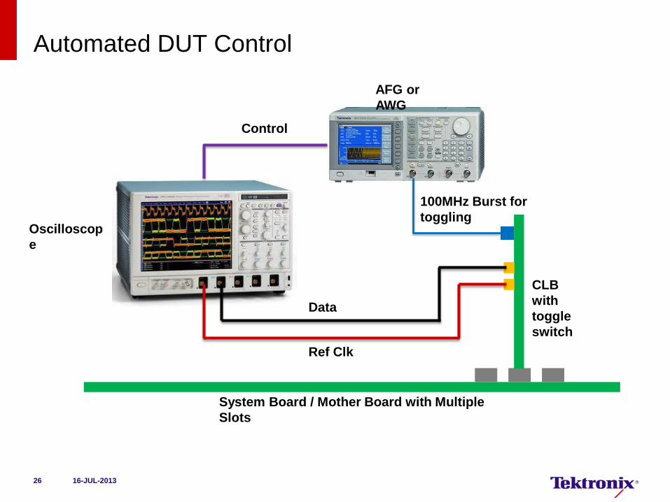
Automated DUT Control
16-JUL-2013 26
Ref Clk
Data
System Board / Mother Board with Multiple
Slots
CLB
with
toggle
switch
Oscilloscop
e
AFG or
AWG
Control
100MHz Burst for
toggling
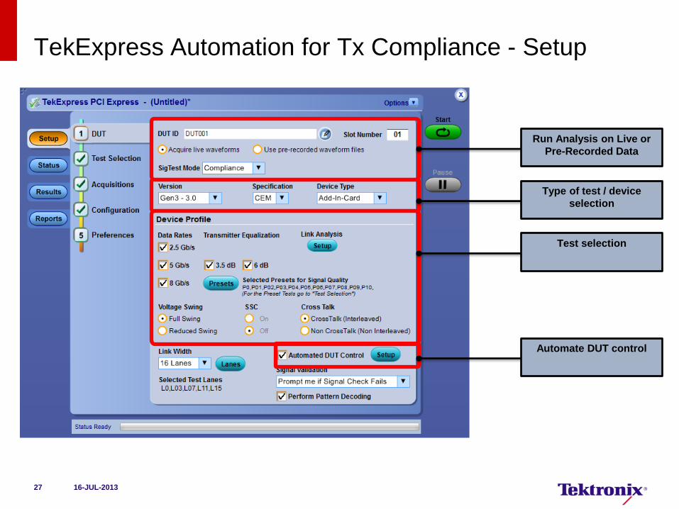
TekExpress Automation for Tx Compliance - Setup
27
Run Analysis on Live or
Pre-Recorded Data
Type of test / device
selection
Test selection
Automate DUT control
16-JUL-2013
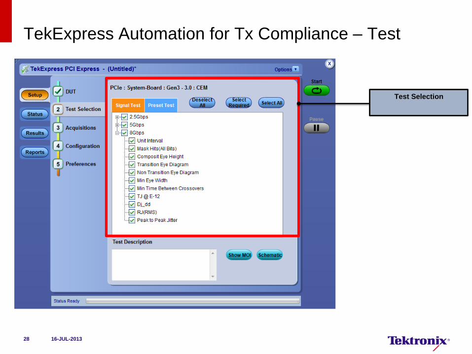
TekExpress Automation for Tx Compliance – Test
28
Test Selection
16-JUL-2013
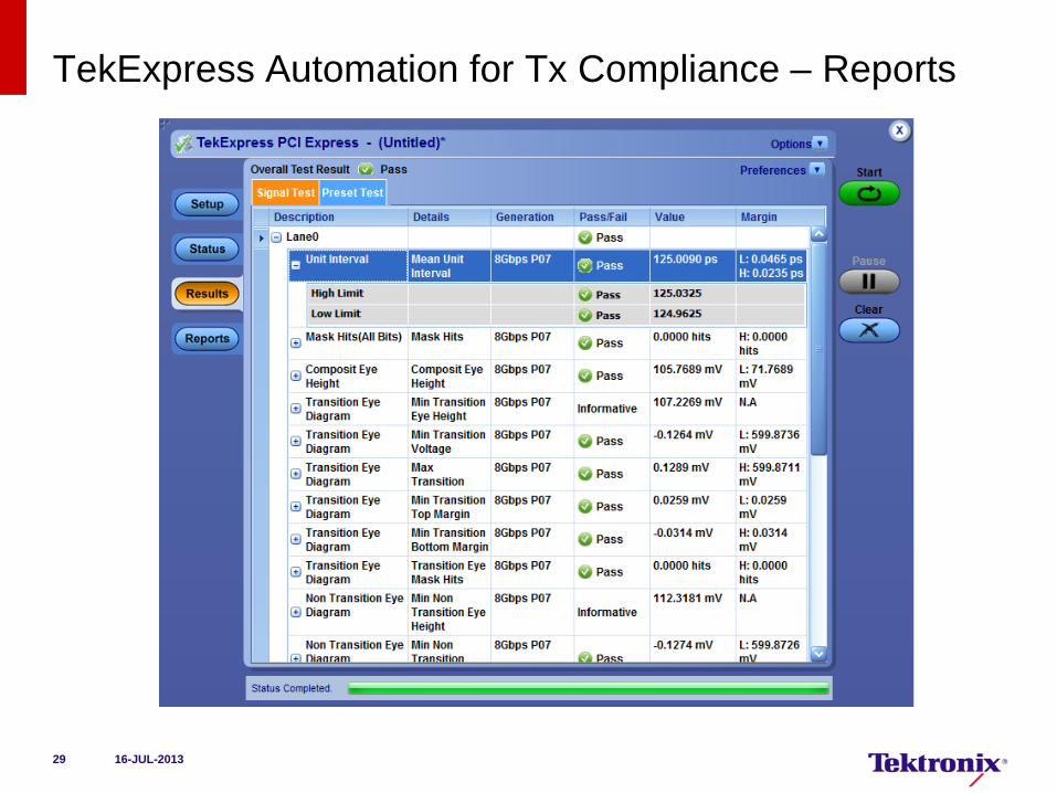
TekExpress Automation for Tx Compliance – Reports
29 16-JUL-2013
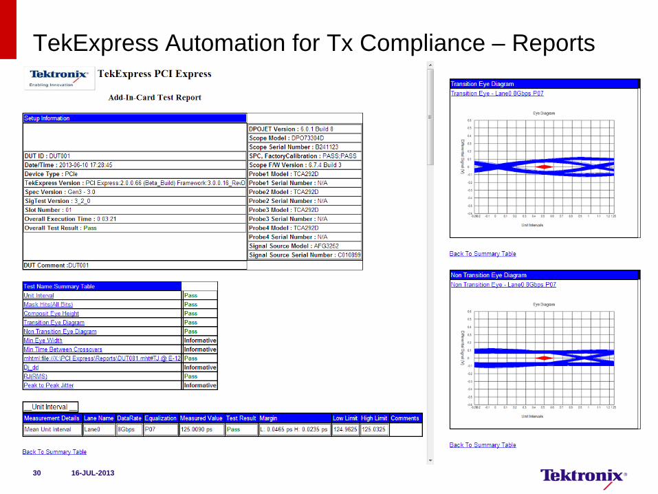
TekExpress Automation for Tx Compliance – Reports
30 16-JUL-2013
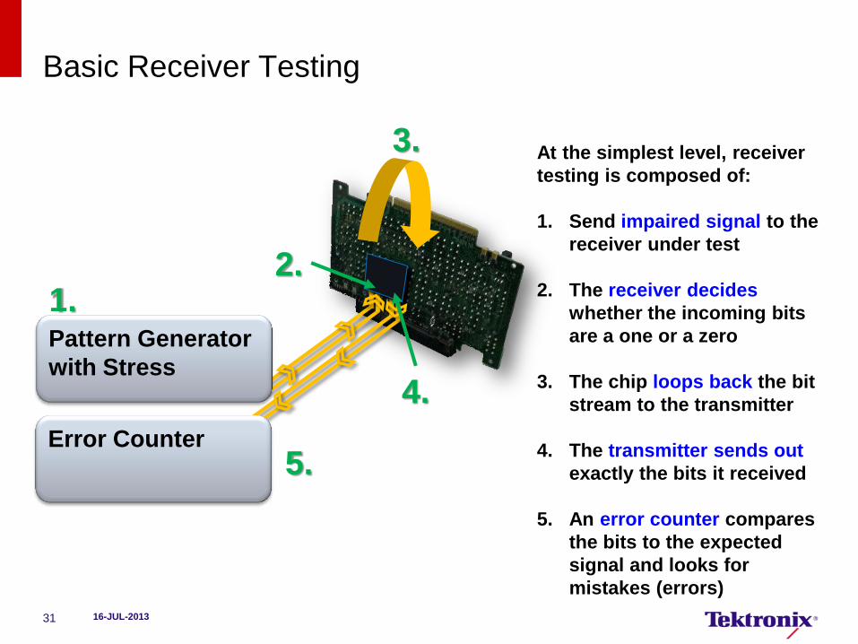
Basic Receiver Testing
16-JUL-2013 31
At the simplest level, receiver
testing is composed of:
1. Send impaired signal to the
receiver under test
2. The receiver decides
whether the incoming bits
are a one or a zero
3. The chip loops back the bit
stream to the transmitter
4. The transmitter sends out
exactly the bits it received
5. An error counter compares
the bits to the expected
signal and looks for
mistakes (errors)
Pattern Generator
with Stress
1. 2.
3.
4.
5. Error Counter
June 5, 2012 Tektronix Confidential 32
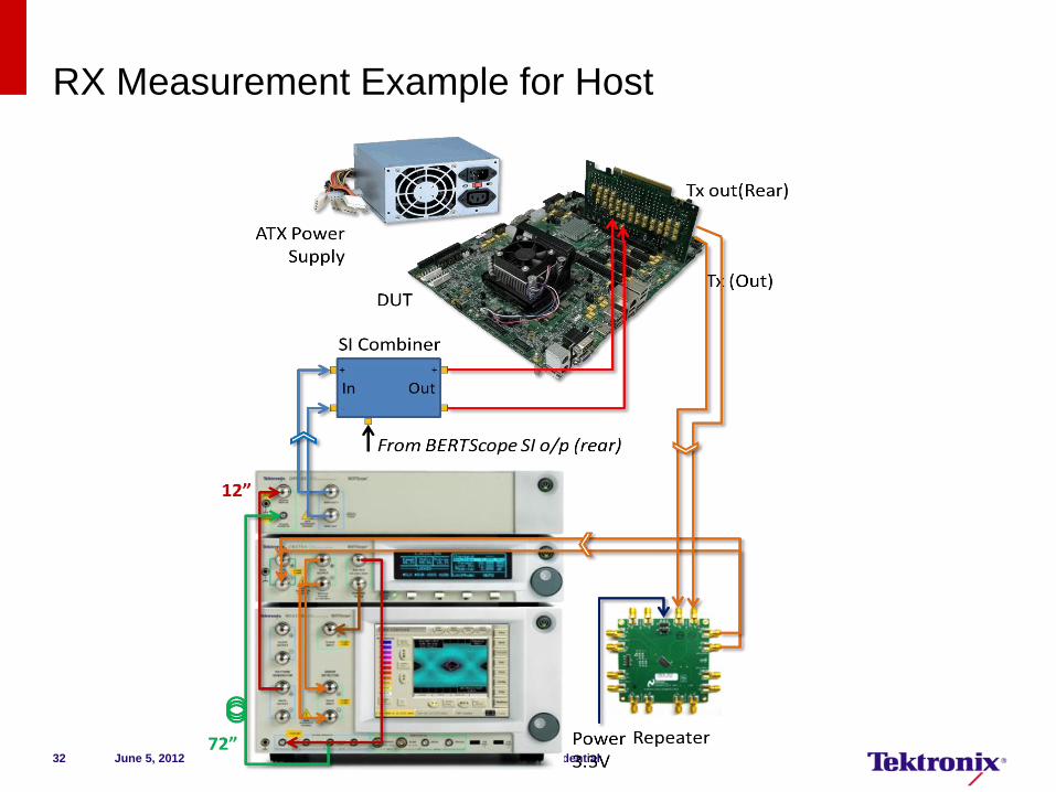
RX Measurement Example for Host
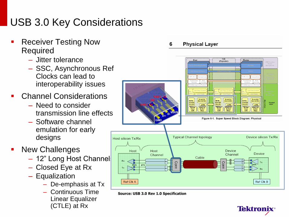
USB 3.0 Key Considerations
Receiver Testing Now Required
– Jitter tolerance
– SSC, Asynchronous Ref Clocks can lead to interoperability issues
Channel Considerations – Need to consider
transmission line effects
– Software channel emulation for early designs
New Challenges – 12” Long Host Channels
– Closed Eye at Rx
– Equalization – De-emphasis at Tx
– Continuous Time Linear Equalizer (CTLE) at Rx
Source: USB 3.0 Rev 1.0 Specification
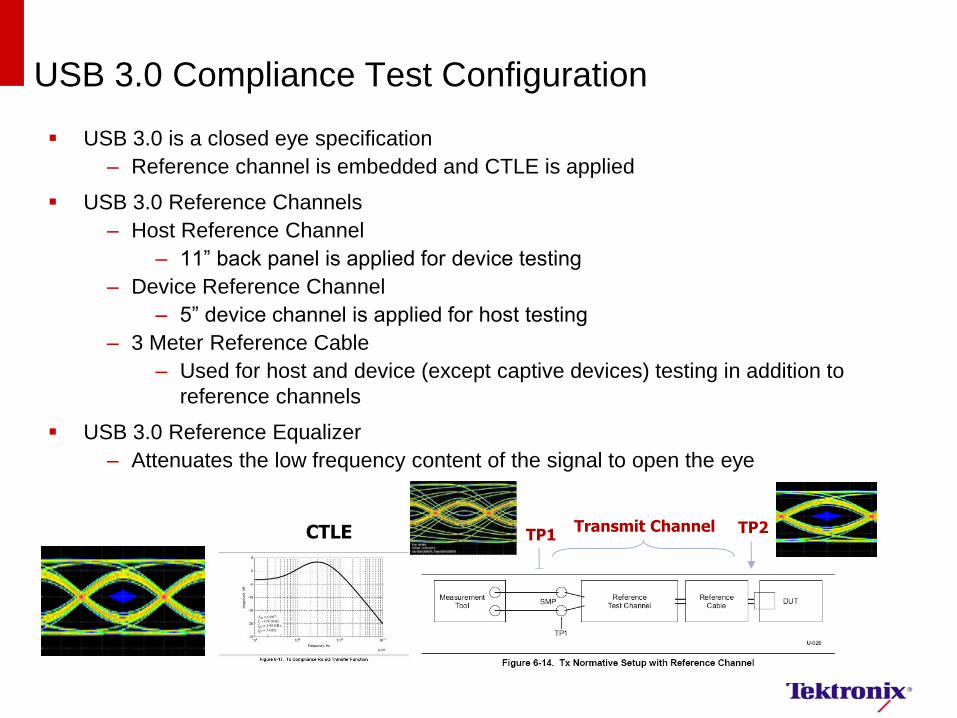
USB 3.0 Compliance Test Configuration
USB 3.0 is a closed eye specification
– Reference channel is embedded and CTLE is applied
USB 3.0 Reference Channels
– Host Reference Channel
– 11” back panel is applied for device testing
– Device Reference Channel
– 5” device channel is applied for host testing
– 3 Meter Reference Cable
– Used for host and device (except captive devices) testing in addition to
reference channels
USB 3.0 Reference Equalizer
– Attenuates the low frequency content of the signal to open the eye
Transmit Channel CTLE TP1 TP2
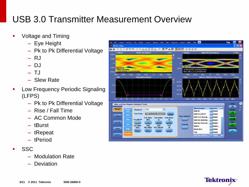
USB 3.0 Transmitter Measurement Overview
Voltage and Timing
– Eye Height
– Pk to Pk Differential Voltage
– RJ
– DJ
– TJ
– Slew Rate
Low Frequency Periodic Signaling
(LFPS)
– Pk to Pk Differential Voltage
– Rise / Fall Time
– AC Common Mode
– tBurst
– tRepeat
– tPeriod
SSC
– Modulation Rate
– Deviation
3/11 © 2011 Tektronix 55W-26800-0

Complete USB 3.0 Transmitter Solution DPO/DSA70000 Series Oscilloscopes
Go Beyond Compliance Testing
– Debug Suite with DPOJET
– SDLA for Channel Modeling
– Tektronix Super Speed USB
Fixtures
Automation software for
characterization and compliance
– TekExpress with option USB-TX
(includes option USB3)
Recommended Scope
– 12.5 GHz Real-Time Scope
– 50 GS/s Sample Rate
– P7313SMA Differential Probe
(Optional)
TF-USB3-AB-KIT
Opt. USB3
Opt. USB-TX
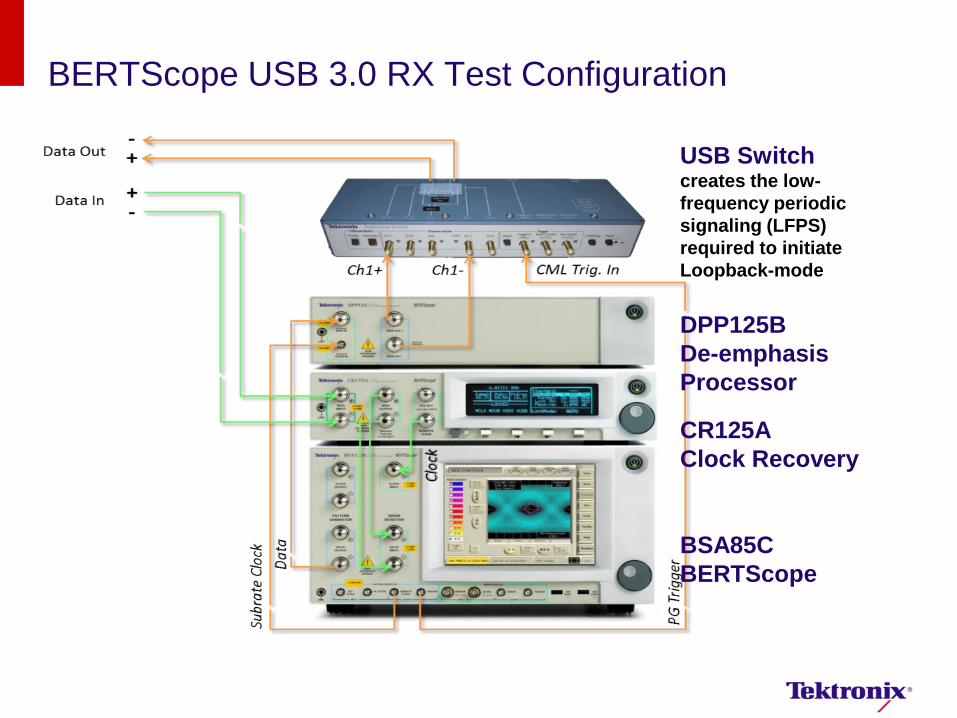
BERTScope USB 3.0 RX Test Configuration
USB Switch creates the low-
frequency periodic
signaling (LFPS)
required to initiate
Loopback-mode
DPP125B
De-emphasis
Processor
CR125A
Clock Recovery
BSA85C
BERTScope
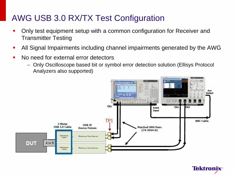
AWG USB 3.0 RX/TX Test Configuration
Only test equipment setup with a common configuration for Receiver and
Transmitter Testing
All Signal Impairments including channel impairments generated by the AWG
No need for external error detectors
– Only Oscilloscope based bit or symbol error detection solution (Ellisys Protocol
Analyzers also supported)
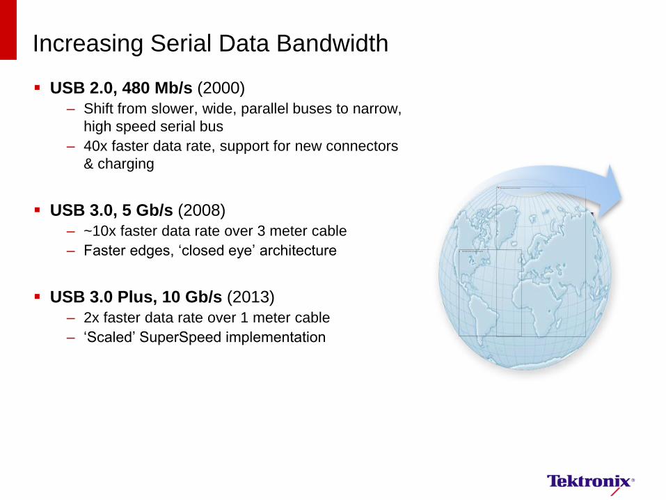
Increasing Serial Data Bandwidth
USB 2.0, 480 Mb/s (2000)
– Shift from slower, wide, parallel buses to narrow,
high speed serial bus
– 40x faster data rate, support for new connectors
& charging
USB 3.0, 5 Gb/s (2008)
– ~10x faster data rate over 3 meter cable
– Faster edges, ‘closed eye’ architecture
USB 3.0 Plus, 10 Gb/s (2013)
– 2x faster data rate over 1 meter cable
– ‘Scaled’ SuperSpeed implementation
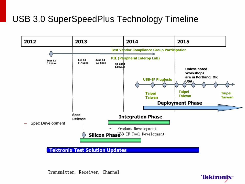
USB 3.0 SuperSpeedPlus Technology Timeline
– Spec Development
2012 2013 2014 2015
Silicon Phase
Integration Phase
– Product Development
– USB-IF Tool Development
Spec Release
Tektronix Test Solution Updates
Transmitter, Receiver, Channel
Deployment Phase
Test Vendor Compliance Group Participation PIL (Peripheral Interop Lab)
Sept 12 0.5 Spec
June 13 0.9 Spec
USB-IF Plugfests
Taipei Taiwan
Unless noted Workshops are in Portland, OR USA
Q4 2013 1.0 Spec
Taipei Taiwan
Feb 13 0.7 Spec
Taipei Taiwan
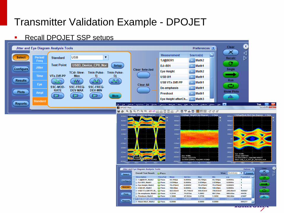
Transmitter Validation Example - DPOJET
Recall DPOJET SSP setups
42
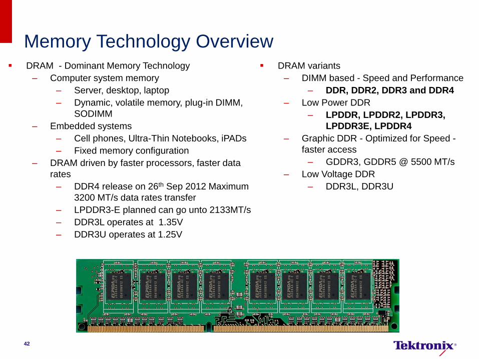
Memory Technology Overview DRAM - Dominant Memory Technology
– Computer system memory
– Server, desktop, laptop
– Dynamic, volatile memory, plug-in DIMM,
SODIMM
– Embedded systems
– Cell phones, Ultra-Thin Notebooks, iPADs
– Fixed memory configuration
– DRAM driven by faster processors, faster data
rates
– DDR4 release on 26th Sep 2012 Maximum
3200 MT/s data rates transfer
– LPDDR3-E planned can go unto 2133MT/s
– DDR3L operates at 1.35V
– DDR3U operates at 1.25V
DRAM variants
– DIMM based - Speed and Performance
– DDR, DDR2, DDR3 and DDR4
– Low Power DDR
– LPDDR, LPDDR2, LPDDR3,
LPDDR3E, LPDDR4
– Graphic DDR - Optimized for Speed -
faster access
– GDDR3, GDDR5 @ 5500 MT/s
– Low Voltage DDR
– DDR3L, DDR3U

Step #1
Step #2
Automated Test Setup
Select DDR Generation Select DDR Rate
Choose measurements (Read / Write / CLK / Addr & Command)
2013/11/5 Tekt
ronix
Inno
vatio
n
Foru
m
2010
44
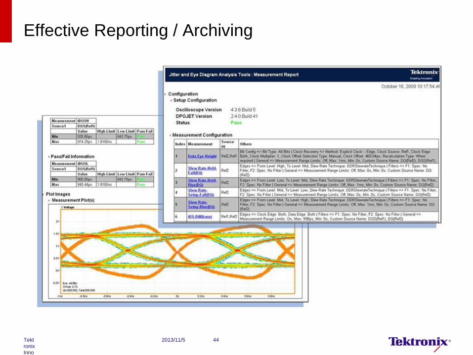
Effective Reporting / Archiving
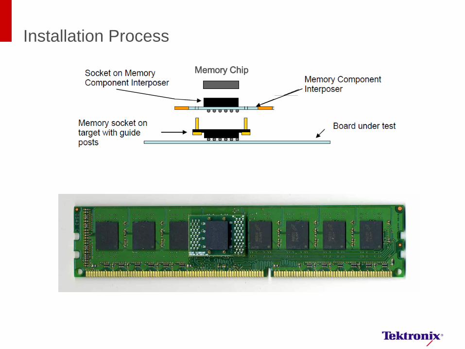
Installation Process
Memory Chip
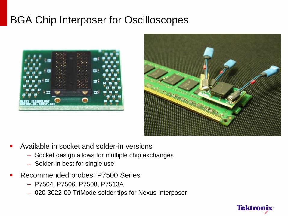
BGA Chip Interposer for Oscilloscopes
Available in socket and solder-in versions
– Socket design allows for multiple chip exchanges
– Solder-in best for single use
Recommended probes: P7500 Series
– P7504, P7506, P7508, P7513A
– 020-3022-00 TriMode solder tips for Nexus Interposer
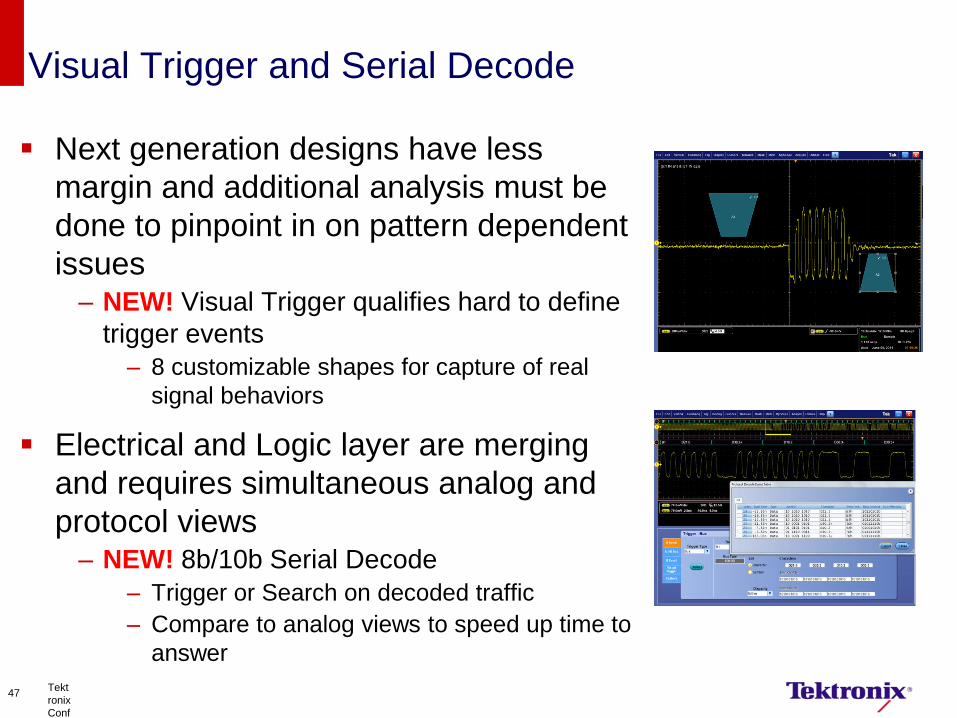
Visual Trigger and Serial Decode
Next generation designs have less
margin and additional analysis must be
done to pinpoint in on pattern dependent
issues – NEW! Visual Trigger qualifies hard to define
trigger events
– 8 customizable shapes for capture of real
signal behaviors
Electrical and Logic layer are merging
and requires simultaneous analog and
protocol views – NEW! 8b/10b Serial Decode
– Trigger or Search on decoded traffic
– Compare to analog views to speed up time to
answer
Tekt
ronix
Conf
ident
ial
47
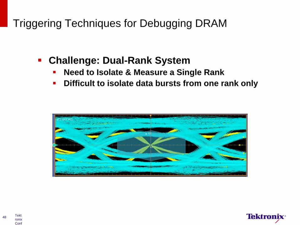
Triggering Techniques for Debugging DRAM
Tekt
ronix
Conf
ident
ial
48
Challenge: Dual-Rank System Need to Isolate & Measure a Single Rank
Difficult to isolate data bursts from one rank only
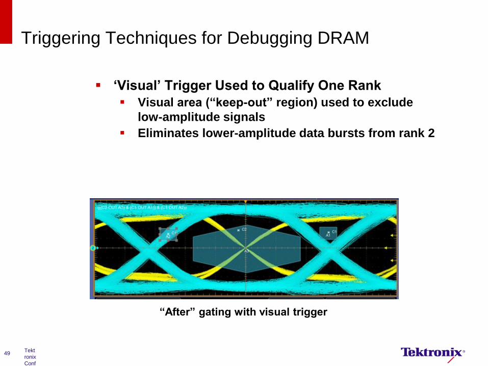
Triggering Techniques for Debugging DRAM
Tekt
ronix
Conf
ident
ial
49
‘Visual’ Trigger Used to Qualify One Rank
Visual area (“keep-out” region) used to exclude
low-amplitude signals
Eliminates lower-amplitude data bursts from rank 2
“After” gating with visual trigger
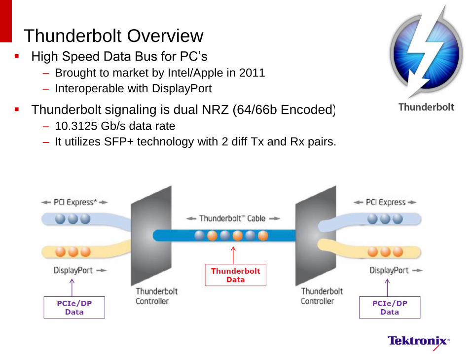
Thunderbolt Overview High Speed Data Bus for PC’s
– Brought to market by Intel/Apple in 2011
– Interoperable with DisplayPort
Thunderbolt signaling is dual NRZ (64/66b Encoded)
– 10.3125 Gb/s data rate
– It utilizes SFP+ technology with 2 diff Tx and Rx pairs.
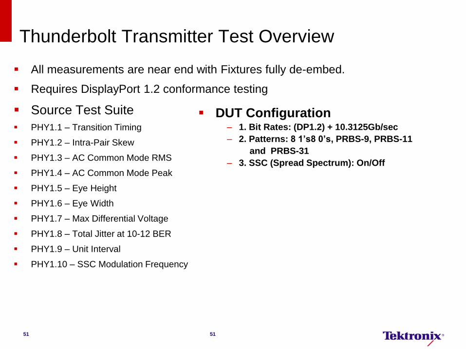
All measurements are near end with Fixtures fully de-embed.
Requires DisplayPort 1.2 conformance testing
Source Test Suite
PHY1.1 – Transition Timing
PHY1.2 – Intra-Pair Skew
PHY1.3 – AC Common Mode RMS
PHY1.4 – AC Common Mode Peak
PHY1.5 – Eye Height
PHY1.6 – Eye Width
PHY1.7 – Max Differential Voltage
PHY1.8 – Total Jitter at 10-12 BER
PHY1.9 – Unit Interval
PHY1.10 – SSC Modulation Frequency
Thunderbolt Transmitter Test Overview
51
DUT Configuration – 1. Bit Rates: (DP1.2) + 10.3125Gb/sec
– 2. Patterns: 8 1’s8 0’s, PRBS-9, PRBS-11
and PRBS-31
– 3. SSC (Spread Spectrum): On/Off
51
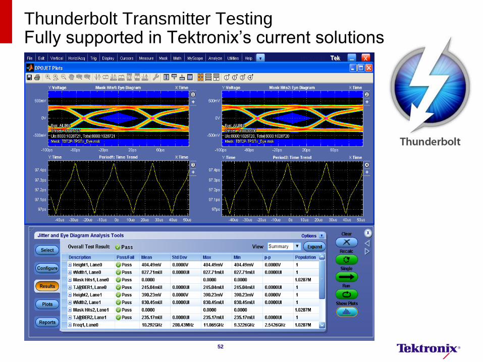
Thunderbolt Transmitter Testing Fully supported in Tektronix’s current solutions
52
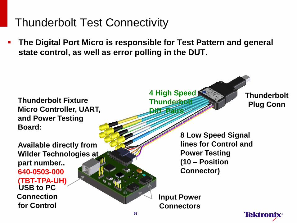
Thunderbolt Test Connectivity
4 High Speed
Thunderbolt
Diff Pairs
8 Low Speed Signal
lines for Control and
Power Testing
(10 – Position
Connector)
Thunderbolt Fixture
Micro Controller, UART,
and Power Testing
Board:
Available directly from
Wilder Technologies at
part number..
640-0503-000
(TBT-TPA-UH)
Input Power
Connectors
USB to PC
Connection
for Control
Thunderbolt
Plug Conn
The Digital Port Micro is responsible for Test Pattern and general
state control, as well as error polling in the DUT.
53
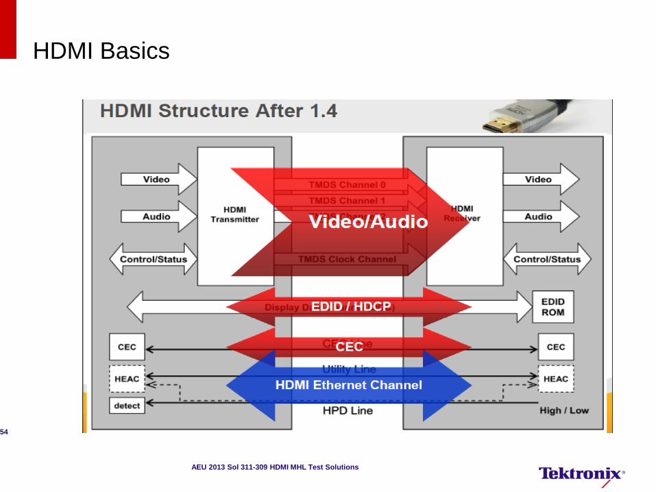
HDMI Basics
54
AEU 2013 Sol 311-309 HDMI MHL Test Solutions
55
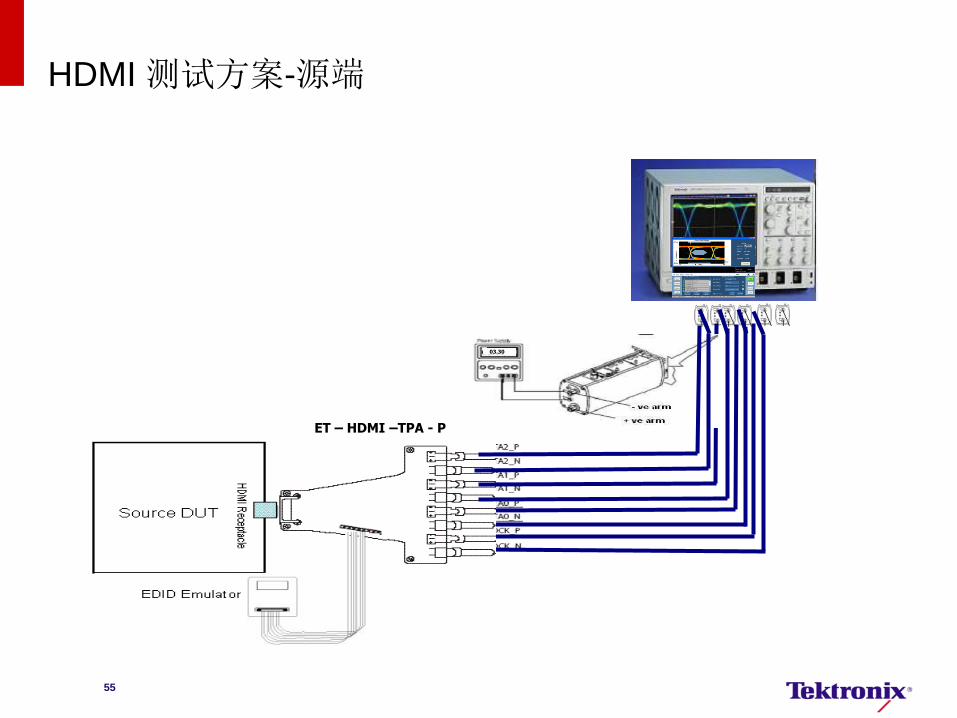
HDMI 测试方案-源端
EFF – HDMI –TPA - P
P7313SMA
Or EDID board
03.30
ET – HDMI –TPA - P
56
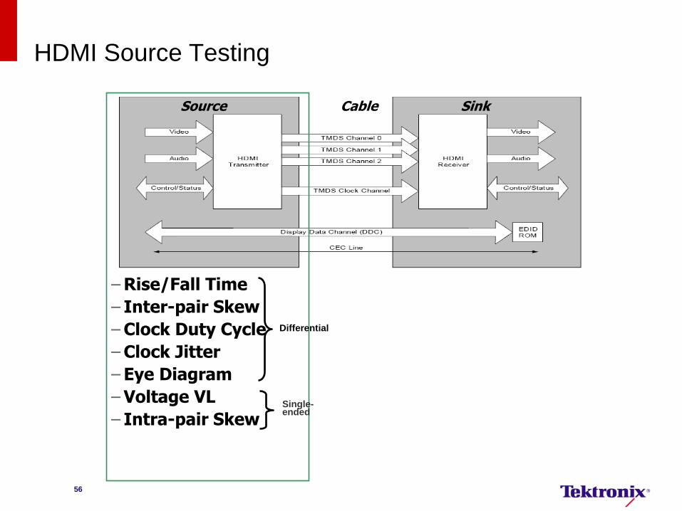
HDMI Source Testing
Source Sink Cable
–Rise/Fall Time
– Inter-pair Skew
–Clock Duty Cycle
–Clock Jitter
– Eye Diagram
–Voltage VL
– Intra-pair Skew
Differential
Single-ended
57
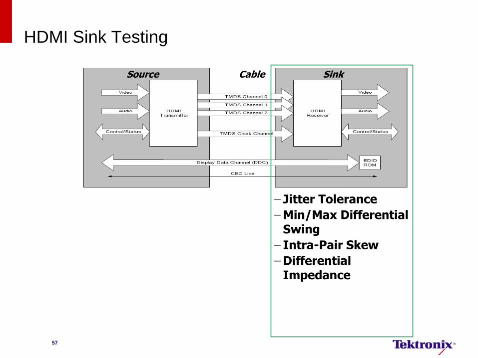
HDMI Sink Testing
Source Sink Cable
– Jitter Tolerance
–Min/Max Differential Swing
– Intra-Pair Skew
–Differential Impedance
HDMI LLC Seminar 2013/11/5 58
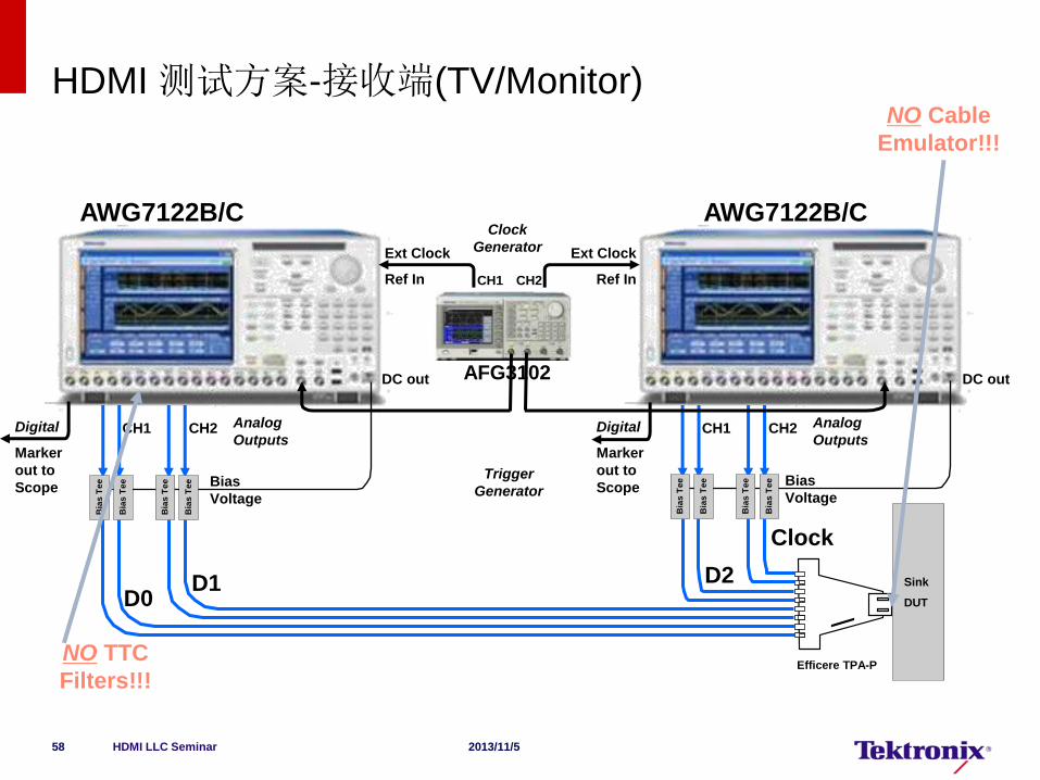
AWG7122B/C AWG7122B/C
Efficere TPA-P
Sink
DUT D0
Clock
D1 D2
Bia
s T
ee
Bia
s T
ee
Bia
s T
ee
Bia
s T
ee
Bia
s T
ee
Bia
s T
ee
Bia
s T
ee
Bia
s T
ee
NO Cable
Emulator!!!
Bias
Voltage
Bias
Voltage
Digital
Marker
out to
Scope
Digital
Marker
out to
Scope
Analog
Outputs CH1 CH2 Analog
Outputs CH1 CH2
Ext Clock
Ref In
Ext Clock
Ref In
DC out DC out AFG3102
CH1 CH2
Trigger
Generator
Clock
Generator
NO TTC
Filters!!!
HDMI 测试方案-接收端(TV/Monitor)
HDMI LLC Seminar 2013/11/5 59
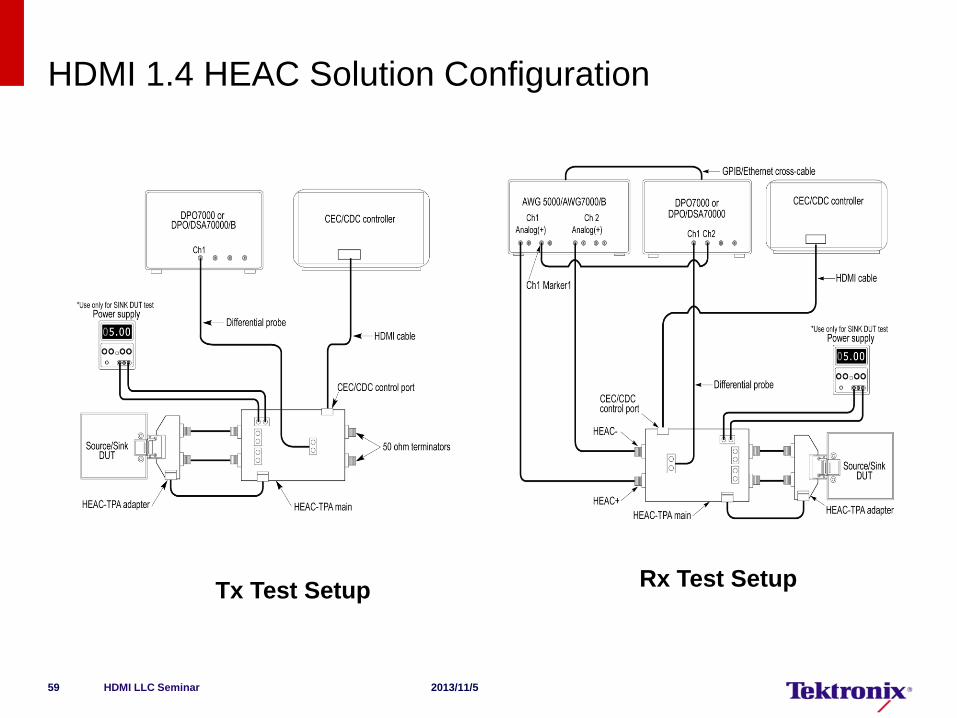
HDMI 1.4 HEAC Solution Configuration
Tx Test Setup Rx Test Setup
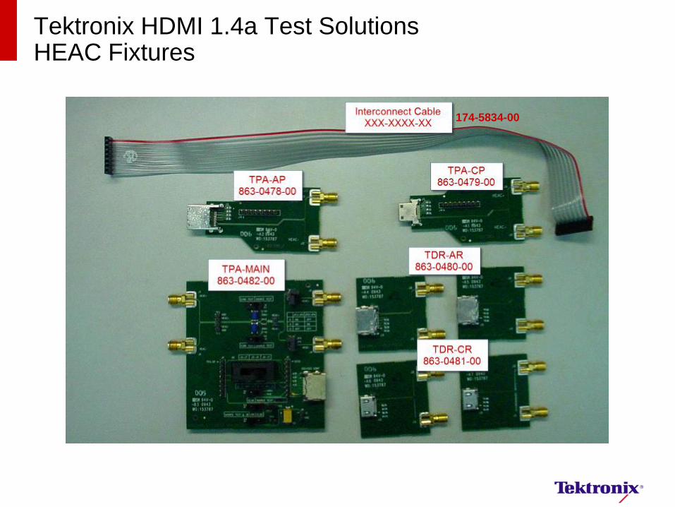
Tektronix HDMI 1.4a Test Solutions HEAC Fixtures
174-5834-00
HDMI LLC Seminar 2013/11/5 61
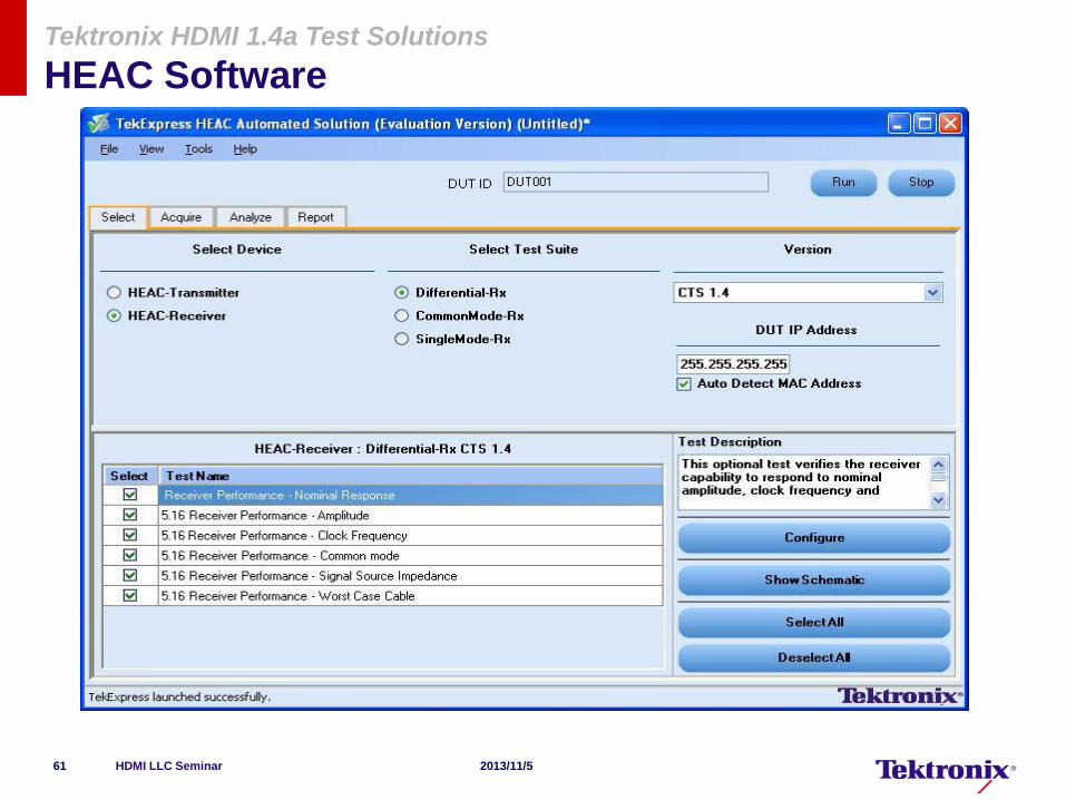
Tektronix HDMI 1.4a Test Solutions
HEAC Software
Proposed HDMI 2.0 features-Not finalized
Uses same Cat 2 Cable and HDMI 1.4b connector
Support 4K 2K 4:4:4 60 Hz – 594Mhz
Support 4K 2K 4:2:0 – 297Mhz
Direct Attach device support
Low level Bit error rate testing
Scrambling is likely to be introduced for rates >340Mcps.
62
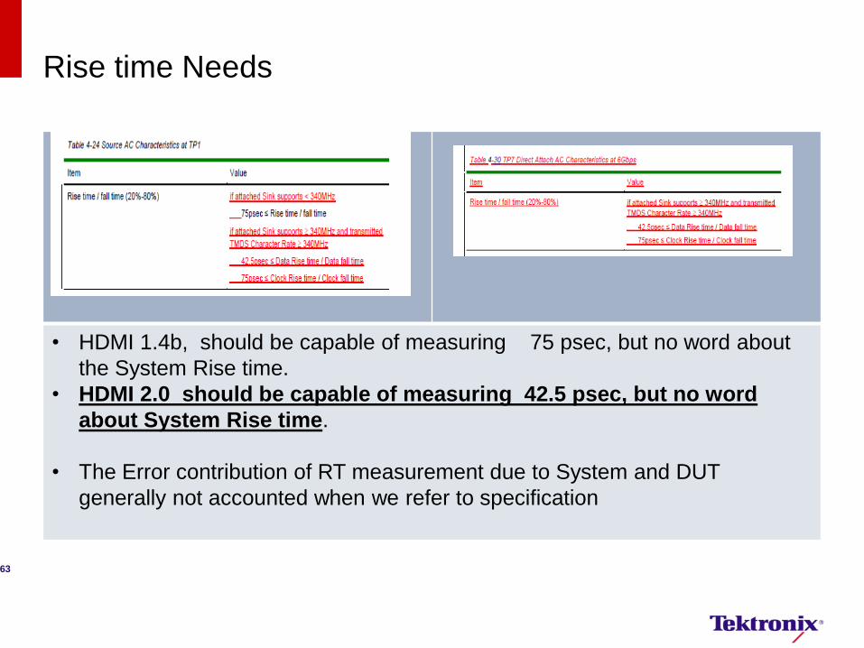
Rise time Needs
• HDMI 1.4b, should be capable of measuring 75 psec, but no word about
the System Rise time.
• HDMI 2.0 should be capable of measuring 42.5 psec, but no word
about System Rise time.
• The Error contribution of RT measurement due to System and DUT
generally not accounted when we refer to specification
63
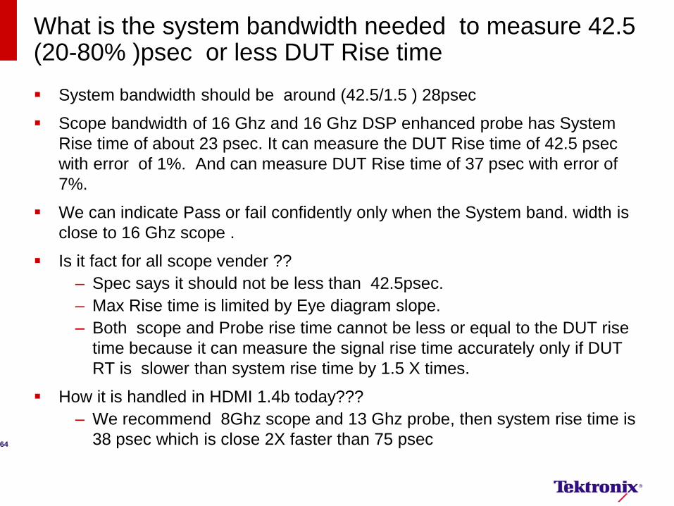
What is the system bandwidth needed to measure 42.5 (20-80% )psec or less DUT Rise time
System bandwidth should be around (42.5/1.5 ) 28psec
Scope bandwidth of 16 Ghz and 16 Ghz DSP enhanced probe has System
Rise time of about 23 psec. It can measure the DUT Rise time of 42.5 psec
with error of 1%. And can measure DUT Rise time of 37 psec with error of
7%.
We can indicate Pass or fail confidently only when the System band. width is
close to 16 Ghz scope .
Is it fact for all scope vender ??
– Spec says it should not be less than 42.5psec.
– Max Rise time is limited by Eye diagram slope.
– Both scope and Probe rise time cannot be less or equal to the DUT rise
time because it can measure the signal rise time accurately only if DUT
RT is slower than system rise time by 1.5 X times.
How it is handled in HDMI 1.4b today???
– We recommend 8Ghz scope and 13 Ghz probe, then system rise time is
38 psec which is close 2X faster than 75 psec
64

Conclusion
16GHz BW scope will give 1% error and hence is recommended for
HDMI 2.0 testing.
HDMI 2.0 RT/FT (20%-80%) data signals is 42.5ps
65
HDMI 2.0 Source Testing-Advanced information
Source Testing 1.4b Vs 2.0
Eye Diagram test is changed
Rest of the tests is same
1.4b CTS test is a pre-requsite for HDMI 2.0
Min 8GHz scope to 16GHz scope
Fixtures and Probes
67
AEU 2013 Sol 311-309 HDMI MHL Test Solutions
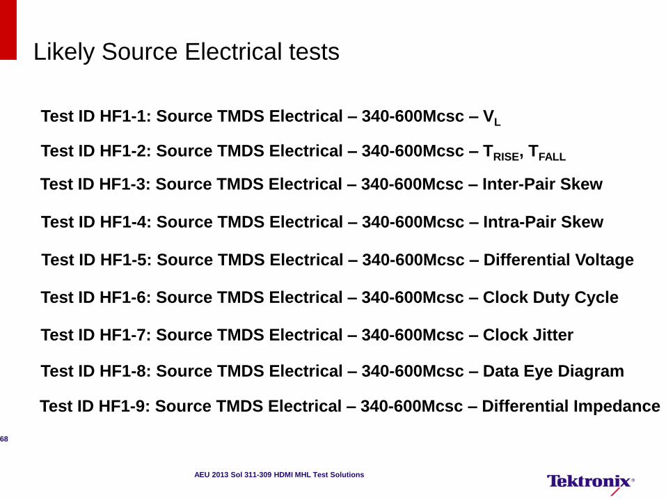
Likely Source Electrical tests
Test ID HF1-1: Source TMDS Electrical – 340-600Mcsc – VL
Test ID HF1-2: Source TMDS Electrical – 340-600Mcsc – TRISE, TFALL
Test ID HF1-3: Source TMDS Electrical – 340-600Mcsc – Inter-Pair Skew
Test ID HF1-4: Source TMDS Electrical – 340-600Mcsc – Intra-Pair Skew
Test ID HF1-5: Source TMDS Electrical – 340-600Mcsc – Differential Voltage
Test ID HF1-6: Source TMDS Electrical – 340-600Mcsc – Clock Duty Cycle
Test ID HF1-7: Source TMDS Electrical – 340-600Mcsc – Clock Jitter
Test ID HF1-8: Source TMDS Electrical – 340-600Mcsc – Data Eye Diagram
Test ID HF1-9: Source TMDS Electrical – 340-600Mcsc – Differential Impedance
68
AEU 2013 Sol 311-309 HDMI MHL Test Solutions
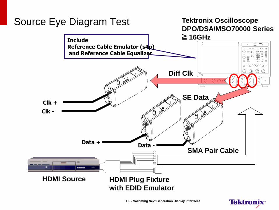
Source Eye Diagram Test
SMA Pair Cable
HDMI Source
Clk +
Clk -
Tektronix Oscilloscope
DPO/DSA/MSO70000 Series
≧ 16GHz Include Reference Cable Emulator (s4p) and Reference Cable Equalizer
HDMI Plug Fixture
with EDID Emulator
Data + Data -
Diff Clk
SE Data
TIF - Validating Next Generation Display Interfaces
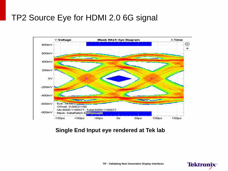
TP2 Source Eye for HDMI 2.0 6G signal
Single End Input eye rendered at Tek lab
TIF - Validating Next Generation Display Interfaces
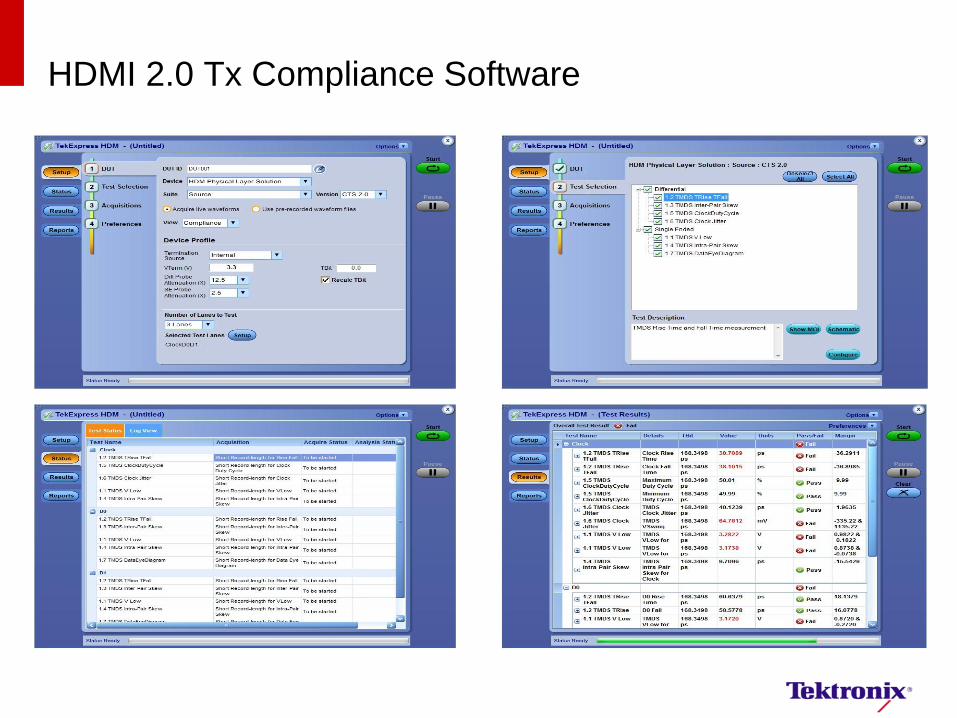
HDMI 2.0 Tx Compliance Software
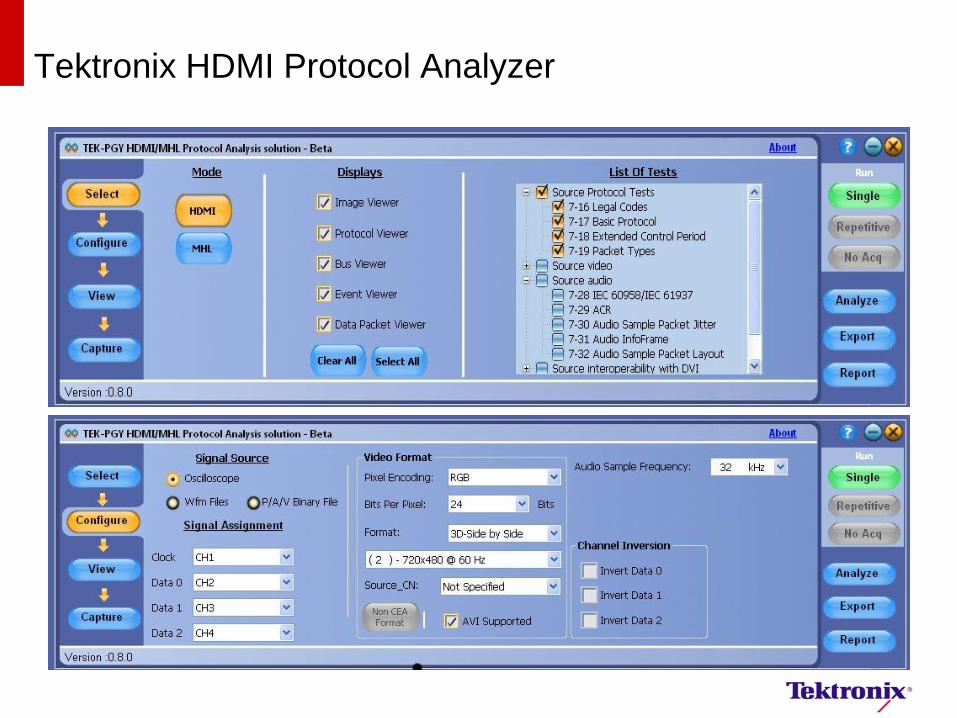
Tektronix HDMI Protocol Analyzer
MHL Introduction
MHL Customer Presentation
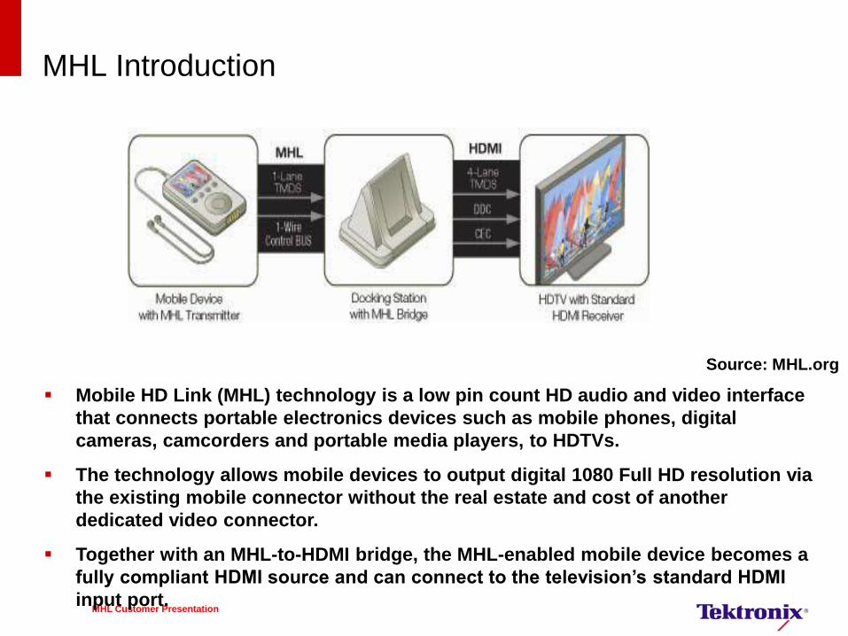
Mobile HD Link (MHL) technology is a low pin count HD audio and video interface
that connects portable electronics devices such as mobile phones, digital
cameras, camcorders and portable media players, to HDTVs.
The technology allows mobile devices to output digital 1080 Full HD resolution via
the existing mobile connector without the real estate and cost of another
dedicated video connector.
Together with an MHL-to-HDMI bridge, the MHL-enabled mobile device becomes a
fully compliant HDMI source and can connect to the television’s standard HDMI
input port.
V Bus
Source: MHL.org
MHL Introduction
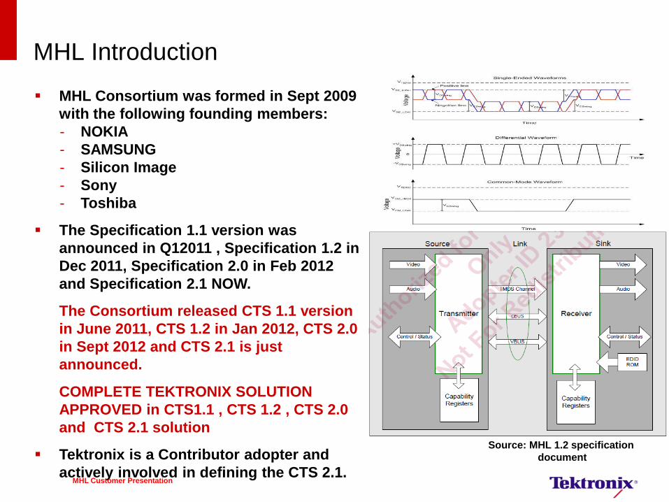
Source: MHL 1.2 specification
document
MHL Consortium was formed in Sept 2009
with the following founding members:
- NOKIA
- SAMSUNG
- Silicon Image
- Sony
- Toshiba
The Specification 1.1 version was
announced in Q12011 , Specification 1.2 in
Dec 2011, Specification 2.0 in Feb 2012
and Specification 2.1 NOW.
The Consortium released CTS 1.1 version
in June 2011, CTS 1.2 in Jan 2012, CTS 2.0
in Sept 2012 and CTS 2.1 is just
announced.
COMPLETE TEKTRONIX SOLUTION
APPROVED in CTS1.1 , CTS 1.2 , CTS 2.0
and CTS 2.1 solution
Tektronix is a Contributor adopter and
actively involved in defining the CTS 2.1. MHL Customer Presentation
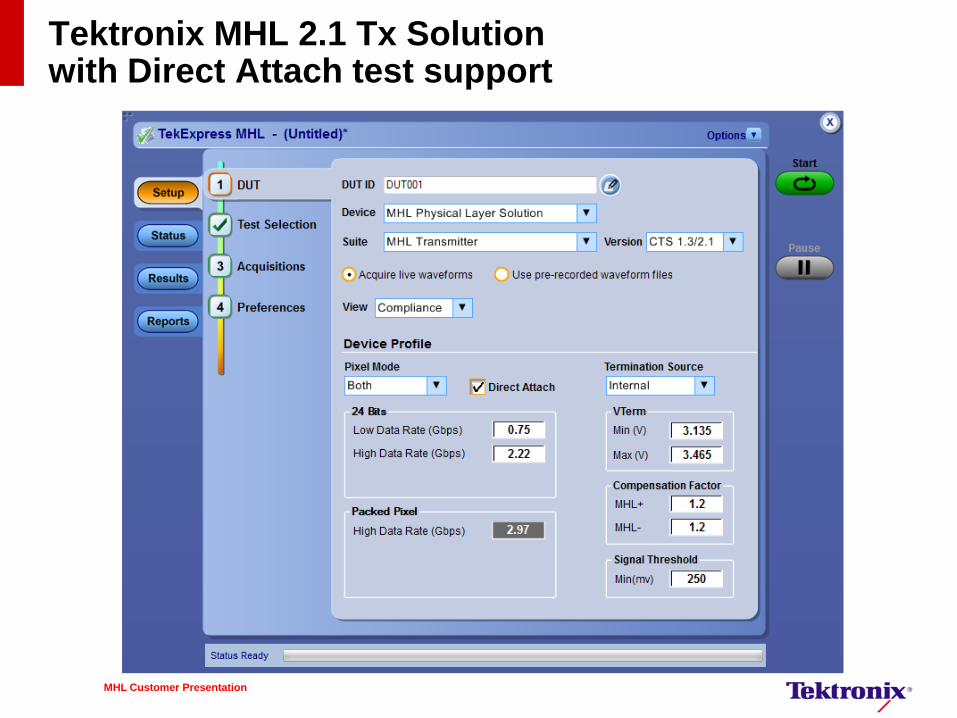
Tektronix MHL 2.1 Tx Solution with Direct Attach test support
MHL Customer Presentation
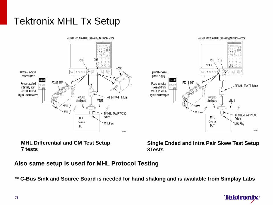
Tektronix MHL Tx Setup
MHL Differential and CM Test Setup
7 tests Single Ended and Intra Pair Skew Test Setup
3Tests
Also same setup is used for MHL Protocol Testing
** C-Bus Sink and Source Board is needed for hand shaking and is available from Simplay Labs
76
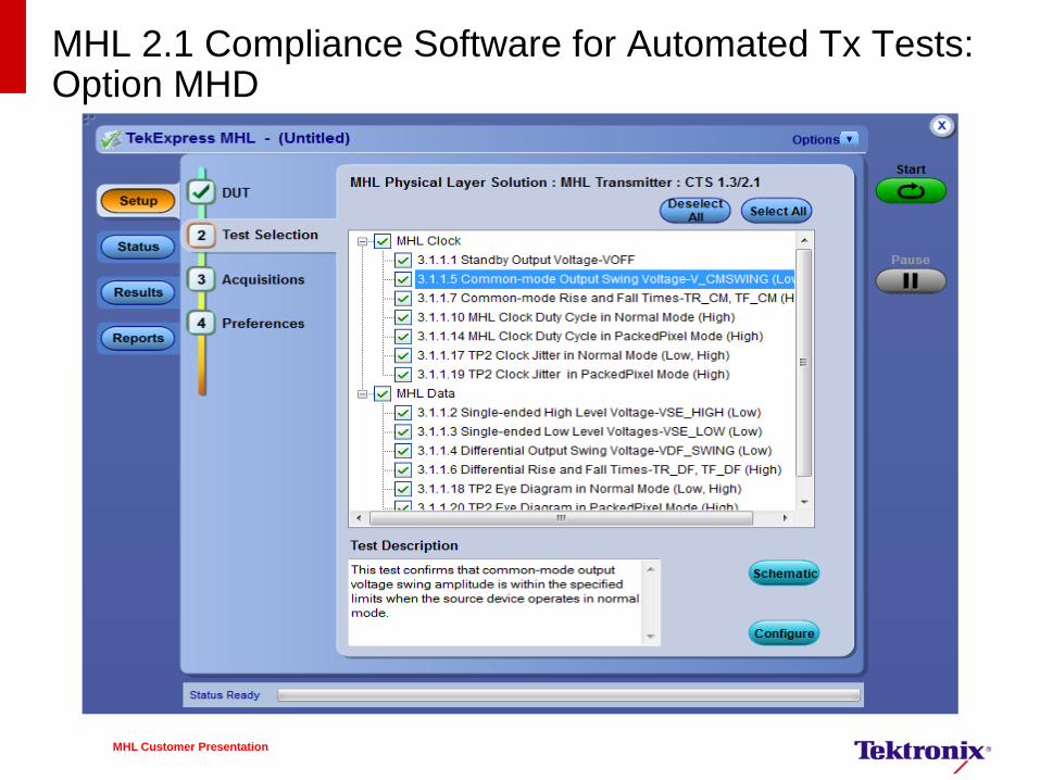
MHL 2.1 Compliance Software for Automated Tx Tests: Option MHD
MHL Customer Presentation
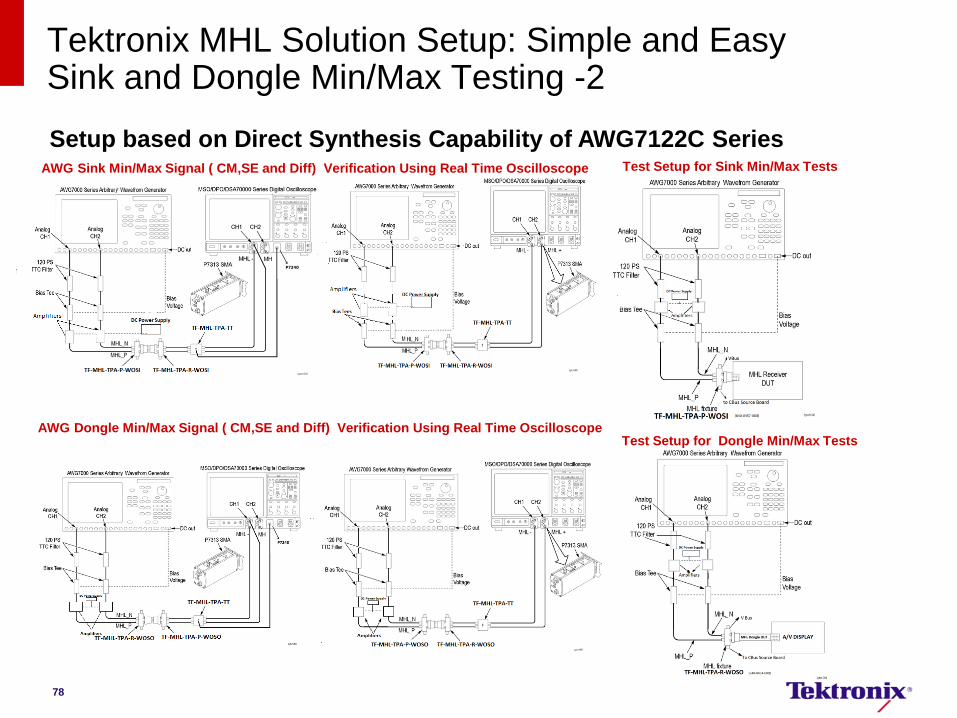
Tektronix MHL Solution Setup: Simple and Easy Sink and Dongle Min/Max Testing -2
Setup based on Direct Synthesis Capability of AWG7122C Series Test Setup for Sink Min/Max Tests
Test Setup for Dongle Min/Max Tests
AWG Sink Min/Max Signal ( CM,SE and Diff) Verification Using Real Time Oscilloscope
78
AWG Dongle Min/Max Signal ( CM,SE and Diff) Verification Using Real Time Oscilloscope

Tektronix MHL Protocol Analyzer
79
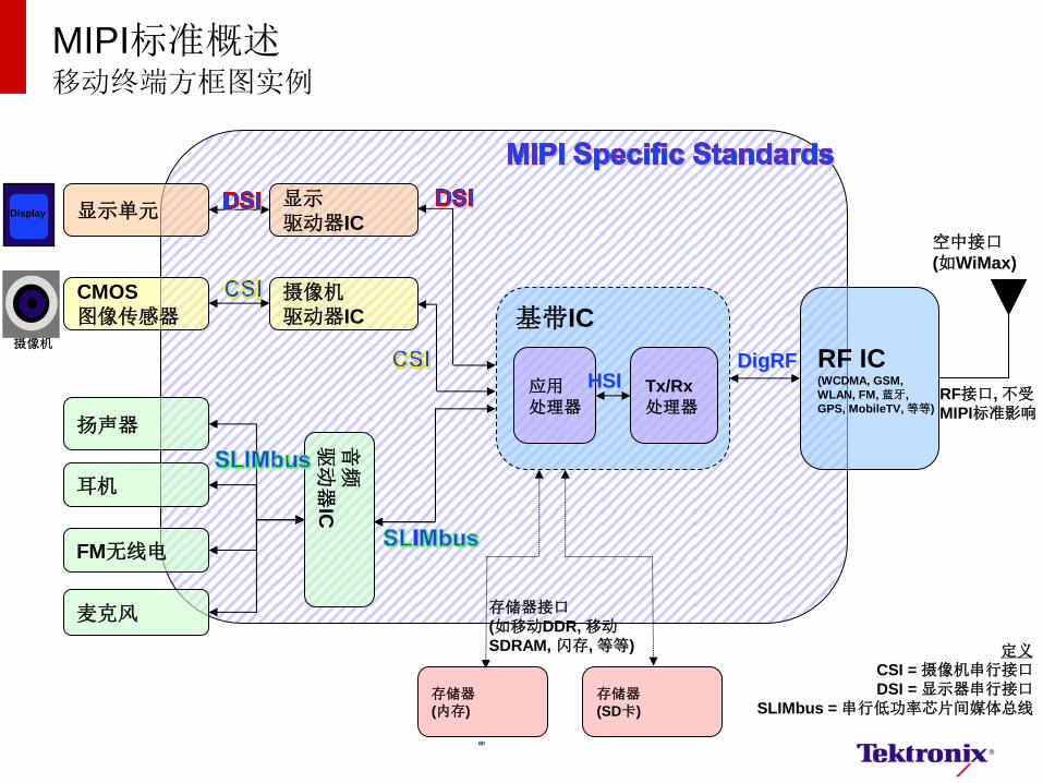
MIPI标准概述 移动终端方框图实例
显示单元
CMOS
图像传感器
RF IC (WCDMA, GSM,
WLAN, FM, 蓝牙,
GPS, MobileTV, 等等)
摄像机
驱动器IC
显示
驱动器IC
扬声器
耳机
音频
驱动
器IC
FM无线电
麦克风
DigRF
基带IC
Tx/Rx
处理器
应用
处理器 RF接口, 不受
MIPI标准影响
空中接口
(如WiMax)
存储器
(内存)
存储器
(SD卡)
存储器接口
(如移动DDR, 移动SDRAM, 闪存, 等等)
HSI
Display
摄像机
定义
CSI = 摄像机串行接口
DSI = 显示器串行接口
SLIMbus = 串行低功率芯片间媒体总线
80
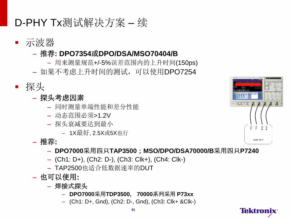
D-PHY Tx测试解决方案 – 续
示波器 – 推荐: DPO7354或DPO/DSA/MSO70404/B
– 用来测量规范+/-5%误差范围内的上升时间(150ps)
– 如果不考虑上升时间的测试,可以使用DPO7254
探头 – 探头考虑因素
– 同时测量单端性能和差分性能
– 动态范围必须>1.2V
– 探头衰减要达到最小
– 1X最好, 2.5X或5X也行
– 推荐:
– DPO7000采用四只TAP3500;MSO/DPO/DSA70000/B采用四只P7240
– (Ch1: D+), (Ch2: D-), (Ch3: Clk+), (Ch4: Clk-)
– TAP2500也适合低数据速率的DUT
– 也可以使用:
– 焊接式探头
– DPO7000采用TDP3500, 70000系列采用 P73xx
– (Ch1: D+, Gnd), (Ch2: D-, Gnd), (Ch3: Clk+ &Clk-)
81
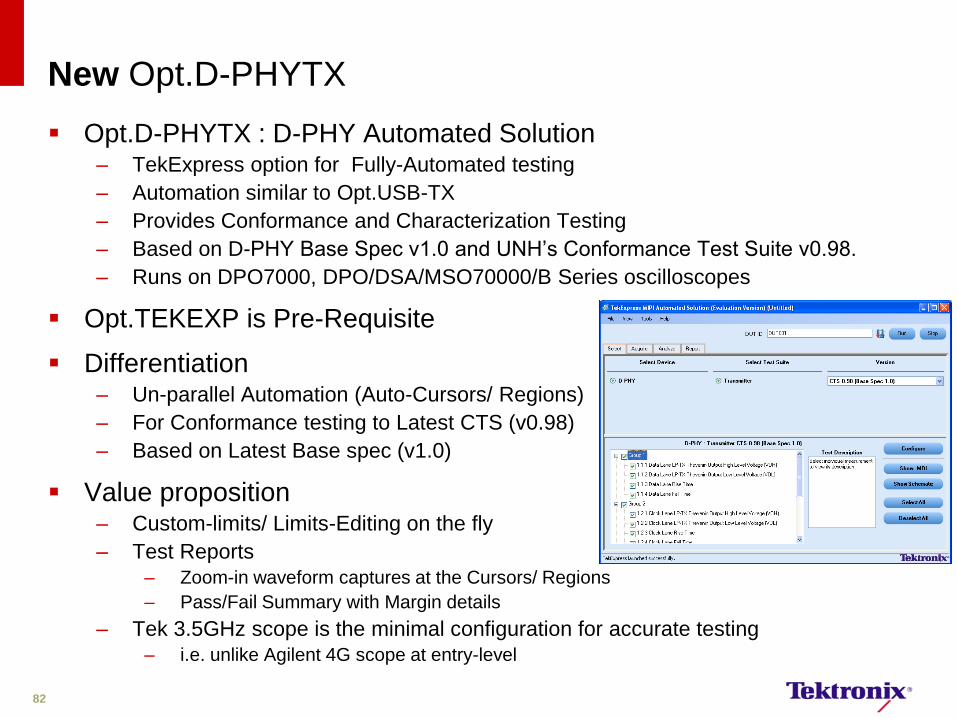
New Opt.D-PHYTX
Opt.D-PHYTX : D-PHY Automated Solution – TekExpress option for Fully-Automated testing
– Automation similar to Opt.USB-TX
– Provides Conformance and Characterization Testing
– Based on D-PHY Base Spec v1.0 and UNH’s Conformance Test Suite v0.98.
– Runs on DPO7000, DPO/DSA/MSO70000/B Series oscilloscopes
Opt.TEKEXP is Pre-Requisite
Differentiation – Un-parallel Automation (Auto-Cursors/ Regions)
– For Conformance testing to Latest CTS (v0.98)
– Based on Latest Base spec (v1.0)
Value proposition – Custom-limits/ Limits-Editing on the fly
– Test Reports
– Zoom-in waveform captures at the Cursors/ Regions
– Pass/Fail Summary with Margin details
– Tek 3.5GHz scope is the minimal configuration for accurate testing
– i.e. unlike Agilent 4G scope at entry-level
82
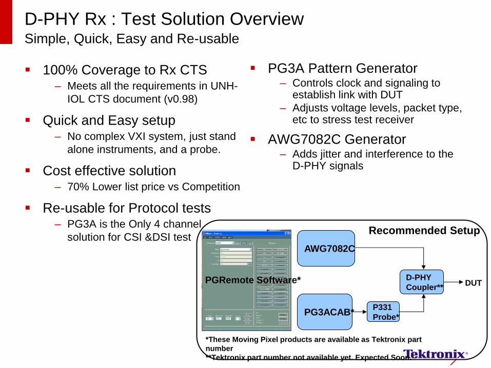
D-PHY Rx : Test Solution Overview Simple, Quick, Easy and Re-usable
100% Coverage to Rx CTS – Meets all the requirements in UNH-
IOL CTS document (v0.98)
Quick and Easy setup – No complex VXI system, just stand
alone instruments, and a probe.
Cost effective solution – 70% Lower list price vs Competition
Re-usable for Protocol tests – PG3A is the Only 4 channel
solution for CSI &DSI test
PG3A Pattern Generator – Controls clock and signaling to
establish link with DUT
– Adjusts voltage levels, packet type, etc to stress test receiver
AWG7082C Generator – Adds jitter and interference to the
D-PHY signals
PGRemote Software*
AWG7082C
PG3ACAB* P331
Probe*
D-PHY
Coupler** DUT
*These Moving Pixel products are available as Tektronix part
number
**Tektronix part number not available yet. Expected Soon.
Recommended Setup
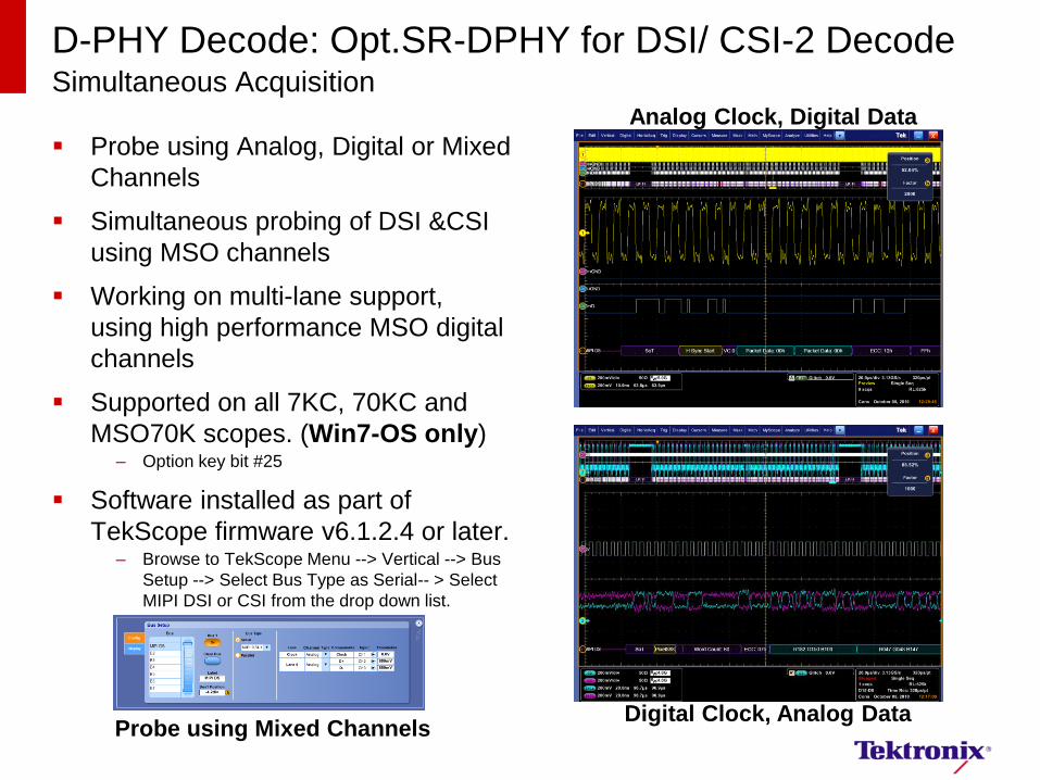
D-PHY Decode: Opt.SR-DPHY for DSI/ CSI-2 Decode Simultaneous Acquisition
Probe using Analog, Digital or Mixed
Channels
Simultaneous probing of DSI &CSI
using MSO channels
Working on multi-lane support,
using high performance MSO digital
channels
Supported on all 7KC, 70KC and
MSO70K scopes. (Win7-OS only) – Option key bit #25
Software installed as part of
TekScope firmware v6.1.2.4 or later. – Browse to TekScope Menu --> Vertical --> Bus
Setup --> Select Bus Type as Serial-- > Select
MIPI DSI or CSI from the drop down list.
Probe using Mixed Channels Digital Clock, Analog Data
Analog Clock, Digital Data
11/5/2013
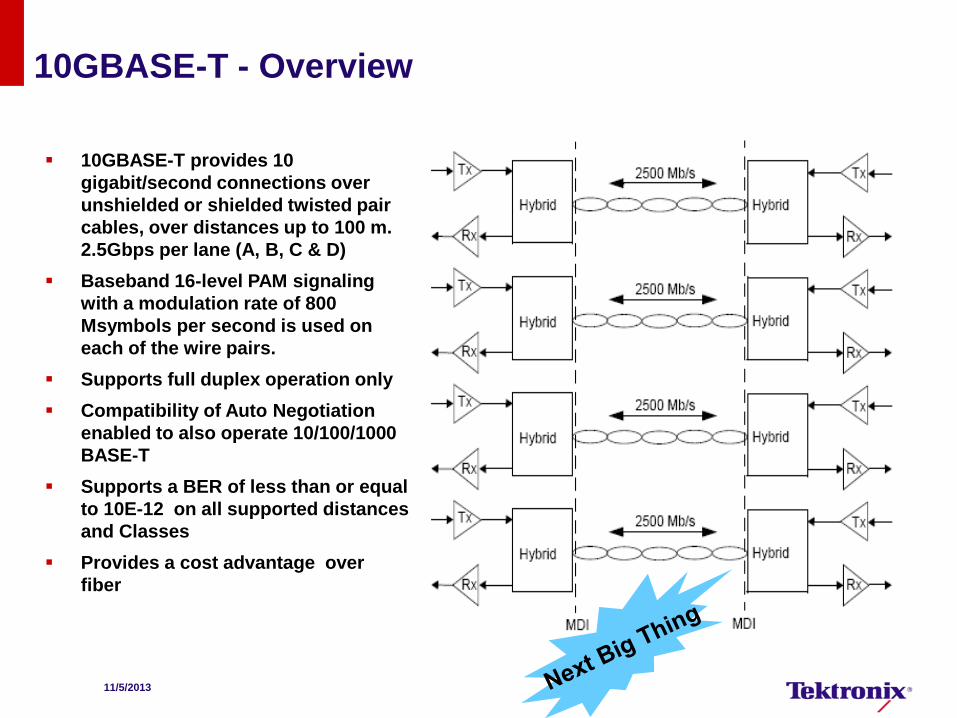
10GBASE-T - Overview
10GBASE-T provides 10
gigabit/second connections over
unshielded or shielded twisted pair
cables, over distances up to 100 m.
2.5Gbps per lane (A, B, C & D)
Baseband 16-level PAM signaling
with a modulation rate of 800
Msymbols per second is used on
each of the wire pairs.
Supports full duplex operation only
Compatibility of Auto Negotiation
enabled to also operate 10/100/1000
BASE-T
Supports a BER of less than or equal
to 10E-12 on all supported distances
and Classes
Provides a cost advantage over
fiber
2013/11/5
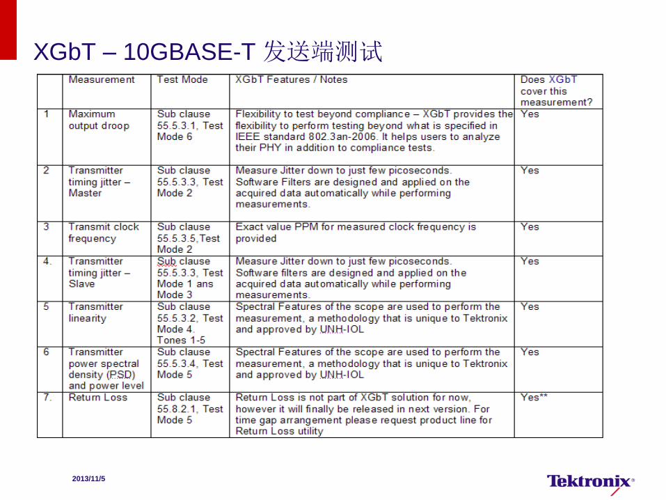
XGbT – 10GBASE-T 发送端测试

2013/11/5
Transmitter Power Spectral Density (PSD) and Power Level 发送端功率谱密度及功率值
目的 : 确保发送端功率谱密度和功率值满足规范要求。
功率值应在3.2dBm~5.2dBm范围内
功率谱密度曲线应介于规范要求的上下限曲线之间。
需进入Test Mode 5
IEEE 标准 802.3an-2006, 55.5.3.4条目。
Test Mode 5:
正常操作模式
11/5/2013
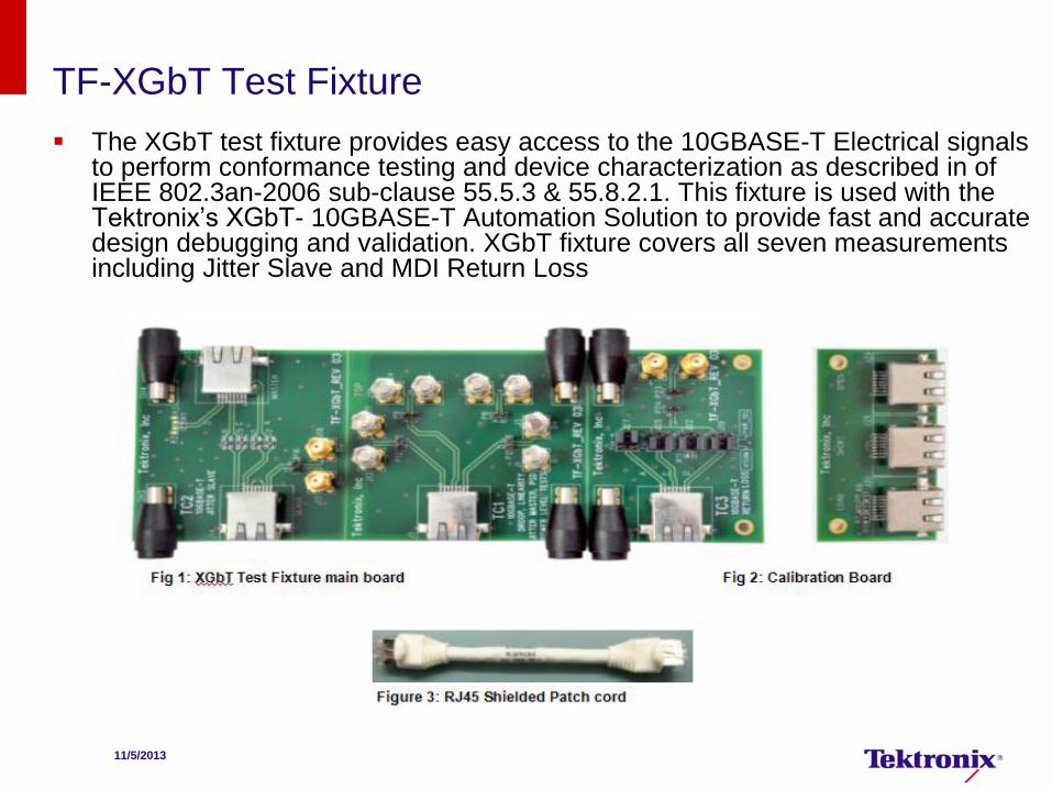
TF-XGbT Test Fixture
The XGbT test fixture provides easy access to the 10GBASE-T Electrical signals to perform conformance testing and device characterization as described in of IEEE 802.3an-2006 sub-clause 55.5.3 & 55.8.2.1. This fixture is used with the Tektronix’s XGbT- 10GBASE-T Automation Solution to provide fast and accurate design debugging and validation. XGbT fixture covers all seven measurements including Jitter Slave and MDI Return Loss
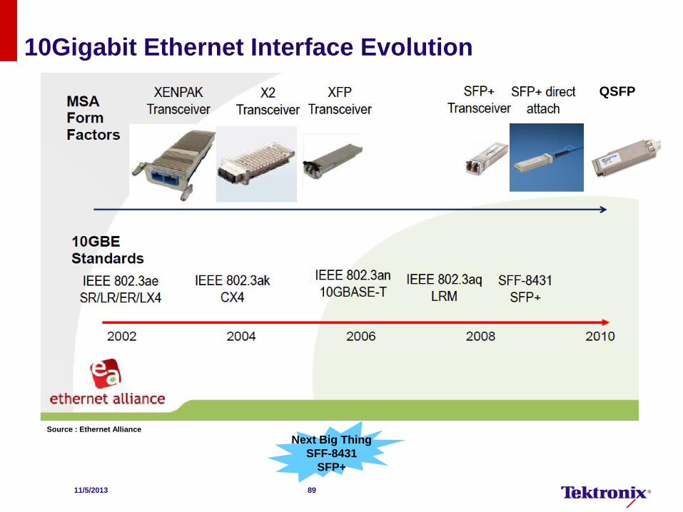
10Gigabit Ethernet Interface Evolution
Next Big Thing
SFF-8431
SFP+
Source : Ethernet Alliance
11/5/2013 89
QSFP
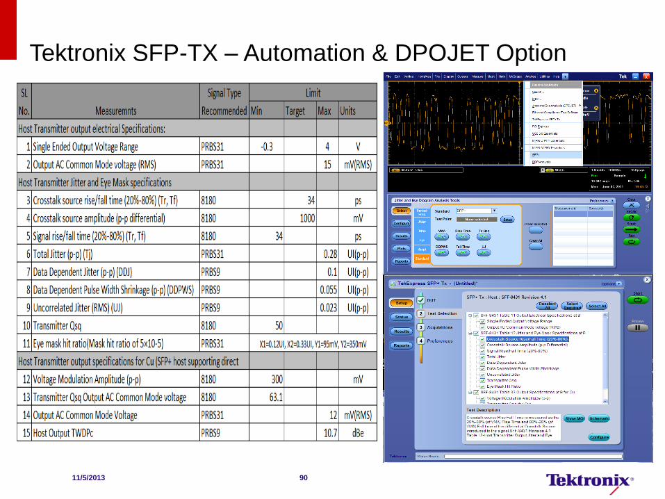
Tektronix SFP-TX – Automation & DPOJET Option
11/5/2013 90
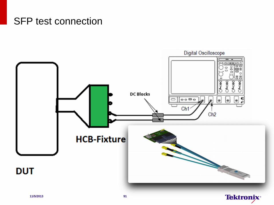
SFP test connection
11/5/2013 91
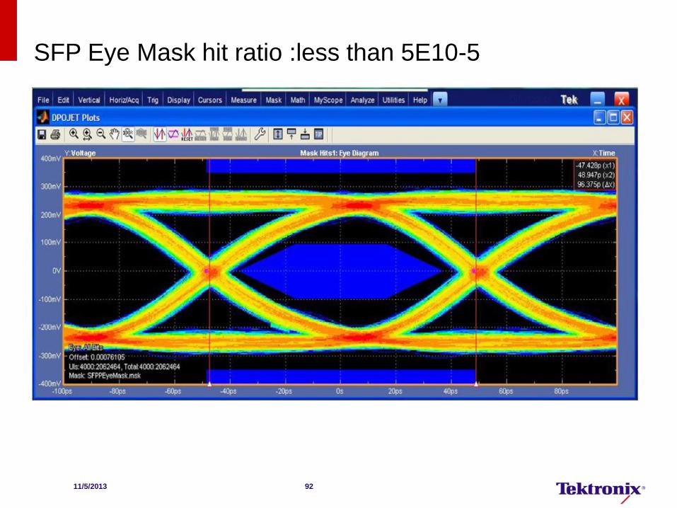
SFP Eye Mask hit ratio :less than 5E10-5
11/5/2013 92
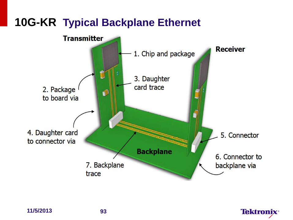
10G-KR Typical Backplane Ethernet
11/5/2013 93
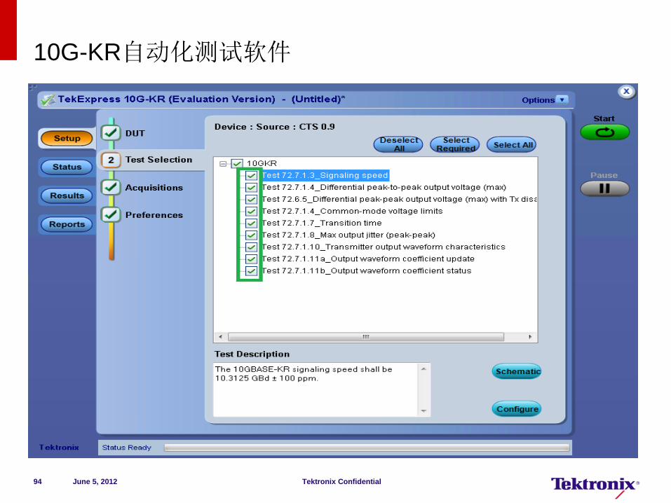
10G-KR自动化测试软件
June 5, 2012 Tektronix Confidential 94
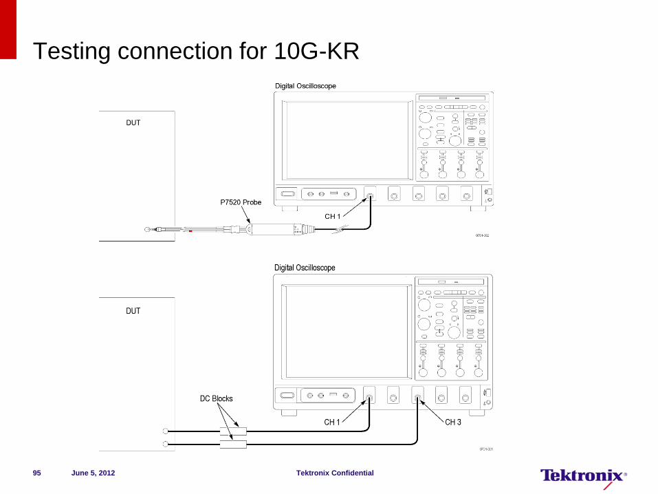
Testing connection for 10G-KR
June 5, 2012 Tektronix Confidential 95
2013/11/5 96
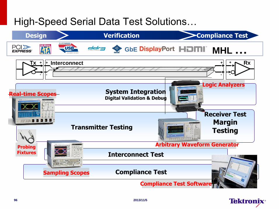
High-Speed Serial Data Test Solutions…
Design Verification Compliance Test
Interconnect Test
Interconnect Tx +
-
+
-
+
-
+
-
Rx
Transmitter Testing
System Integration Digital Validation & Debug
Receiver Test
Margin Testing
Compliance Test
Real-time Scopes
Sampling Scopes
Arbitrary Waveform Generator
Logic Analyzers
Compliance Test Software
Probing Fixtures
GbE MHL …