Embed Size (px)
Citation preview
CMS Week: Trigger Meeting, June 2002. B. Scurlock, University of Florida 1
CSC TrackCSC Track--Finder Finder HW/SW UpdateHW/SW Update
Bobby Scurlock, UFDarin Acosta, UF
Alex Madorski, PNPILev Uvarov, PNPI
Victor Golovtsov, PNPI
CMS Week: Trigger Meeting, June 2002. B. Scurlock, University of Florida 2
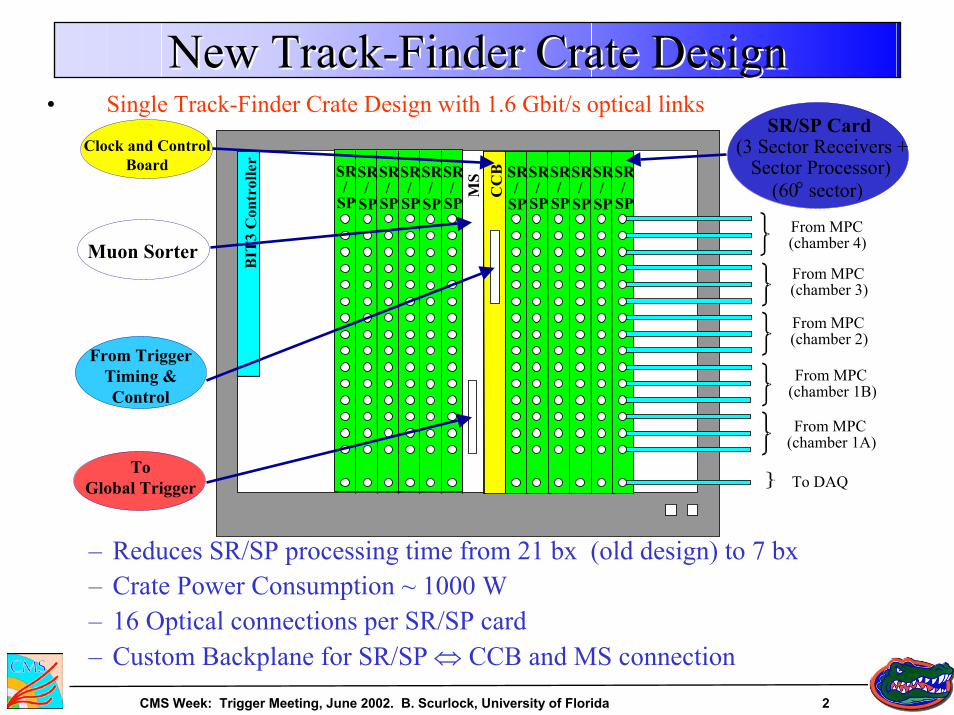
New Track-Finder Crate DesignNew TrackNew Track--Finder Crate DesignFinder Crate Design
SR/
SP
SR/
SP
SR/
SP
SR/
SP
SR/
SP
SR/
SP
SR/
SP
SR/
SP
SR/
SP
SR/
SP
SR/
SP
SR/
SP
CC
B
BIT
3 C
ontr
olle
r
SR/SP Card(3 Sector Receivers +
Sector Processor)(60° sector)
Clock and Control Board
Muon Sorter
ToGlobal Trigger
From Trigger Timing & Control
From MPC(chamber 4)
From MPC(chamber 3)
From MPC(chamber 2)
From MPC(chamber 1B)
From MPC(chamber 1A)
To DAQM
S
• Single Track-Finder Crate Design with 1.6 Gbit/s optical links
– Reduces SR/SP processing time from 21 bx (old design) to 7 bx– Crate Power Consumption ~ 1000 W – 16 Optical connections per SR/SP card– Custom Backplane for SR/SP ⇔ CCB and MS connection
CMS Week: Trigger Meeting, June 2002. B. Scurlock, University of Florida 3
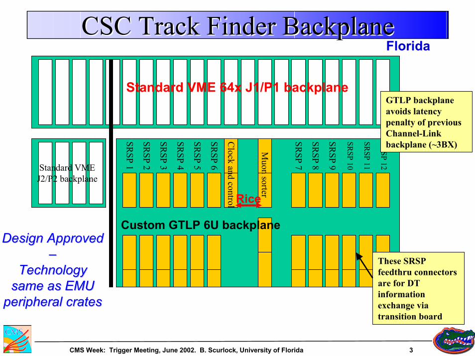
CSC Track Finder BackplaneCSC Track FinderCSC Track Finder BackplaneBackplane
Standard VME 64x J1/P1 backplane
Standard VME J2/P2 backplane
Muon sorter
Clock and control
SRSP 6
SRSP 5
SRSP 4
SRSP 3
SRSP 2
SRSP 1
SRSP 12
SRSP 11
SRSP 10
SRSP 9
SRSP 8
SRSP 7
Custom GTLP 6U backplane
Rice
Florida
These SRSP feedthru connectors are for DT information exchange via transition board
GTLP backplane avoids latency penalty of previous Channel-Link backplane (~3BX)
Design Approved Design Approved ––
Technology Technology same as EMU same as EMU
peripheral cratesperipheral crates
CMS Week: Trigger Meeting, June 2002. B. Scurlock, University of Florida 4
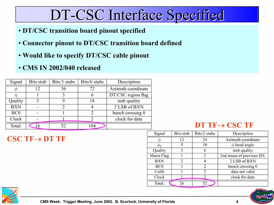
DT-CSC Interface SpecifiedDTDT--CSC Interface SpecifiedCSC Interface Specified• DT/CSC transition board pinout specified
• Connector pinout to DT/CSC transition board defined
• Would like to specify DT/CSC cable pinout
• CMS IN 2002/040 released
DT TF→ CSC TF
CSC TF→ DT TF
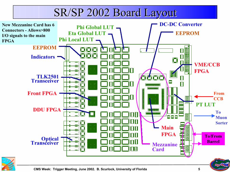
CMS Week: Trigger Meeting, June 2002. B. Scurlock, University of Florida 5
SR/SP 2002 Board LayoutSR/SP 2002 Board LayoutSR/SP 2002 Board Layout
From CCB
To Muon Sorter
To/From Barrel
New Mezzanine Card has 6 Connectors - Allows>800 I/O signals to the main FPGA
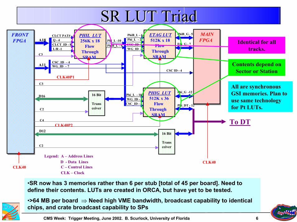
CMS Week: Trigger Meeting, June 2002. B. Scurlock, University of Florida 6
SR LUT TriadSR LUT TriadSR LUT TriadCLCT PAT# - 4Q - 4 Phi_L -10
PhiB_L - 6CLCT_ID - 8L/R -1
CSC_ID - 4
Phi_L - 10WG_ID - 5
Phi_G -12
PhiB_L - 6Phi_L - 2CSC_ID - 4 WG_ID - 7
Eta_G - 7
PhiB_G - 5
CLK40P1
CLK40P2
CLK40
CSC_ID – 4WG_ID – 7
16 Bit
Transceiver
CLK40
C3
PHIL LUT 256K x 18
Flow ThroughSRAM
A18
A11
D16
C2
PHIG LUT512K x 36
FlowThrough
SRAM
ETAG LUT512K x 18
Flow ThroughSRAM
C3
16 Bit
Transceiver
D12
MAINFPGAMAINFPGA
FRONTFPGA
FRONTFPGA
C2
To DTC4
Legend: A – Address LinesD - Data LinesC – Control LinesCLK – Clock
Phi_DT - 12
CSC ID - 4
Contents depend on Sector or Station
Identical for all tracks.
All are synchronous GSI memories. Plan to use same technology for Pt LUTs.
•SR now has 3 memories rather than 6 per stub [total of 45 per board]. Need to define their contents. LUTs are created in ORCA, but have yet to be tested.
•>64 MB per board ⇒ Need high VME bandwidth, broadcast capability to identical chips, and crate broadcast capability to SPs
CMS Week: Trigger Meeting, June 2002. B. Scurlock, University of Florida 7
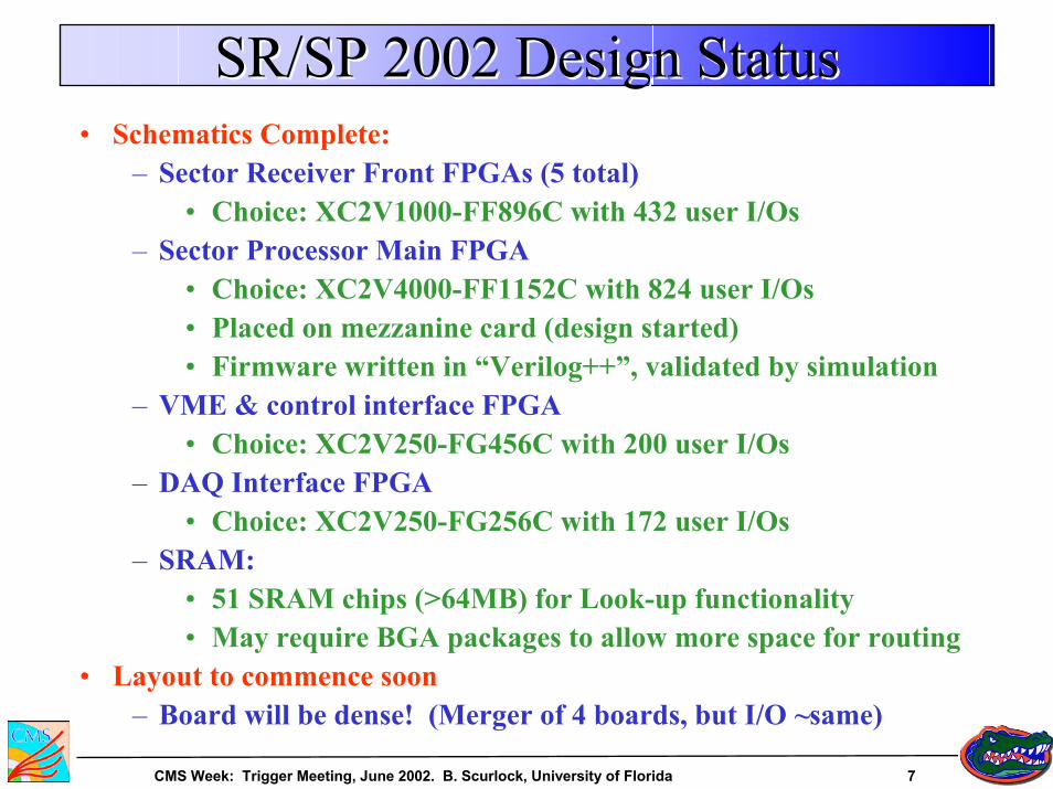
SR/SP 2002 Design StatusSR/SP 2002 Design StatusSR/SP 2002 Design Status• Schematics Complete:
– Sector Receiver Front FPGAs (5 total)• Choice: XC2V1000-FF896C with 432 user I/Os
– Sector Processor Main FPGA• Choice: XC2V4000-FF1152C with 824 user I/Os• Placed on mezzanine card (design started)• Firmware written in “Verilog++”, validated by simulation
– VME & control interface FPGA• Choice: XC2V250-FG456C with 200 user I/Os
– DAQ Interface FPGA• Choice: XC2V250-FG256C with 172 user I/Os
– SRAM:• 51 SRAM chips (>64MB) for Look-up functionality• May require BGA packages to allow more space for routing
• Layout to commence soon– Board will be dense! (Merger of 4 boards, but I/O ~same)
CMS Week: Trigger Meeting, June 2002. B. Scurlock, University of Florida 8
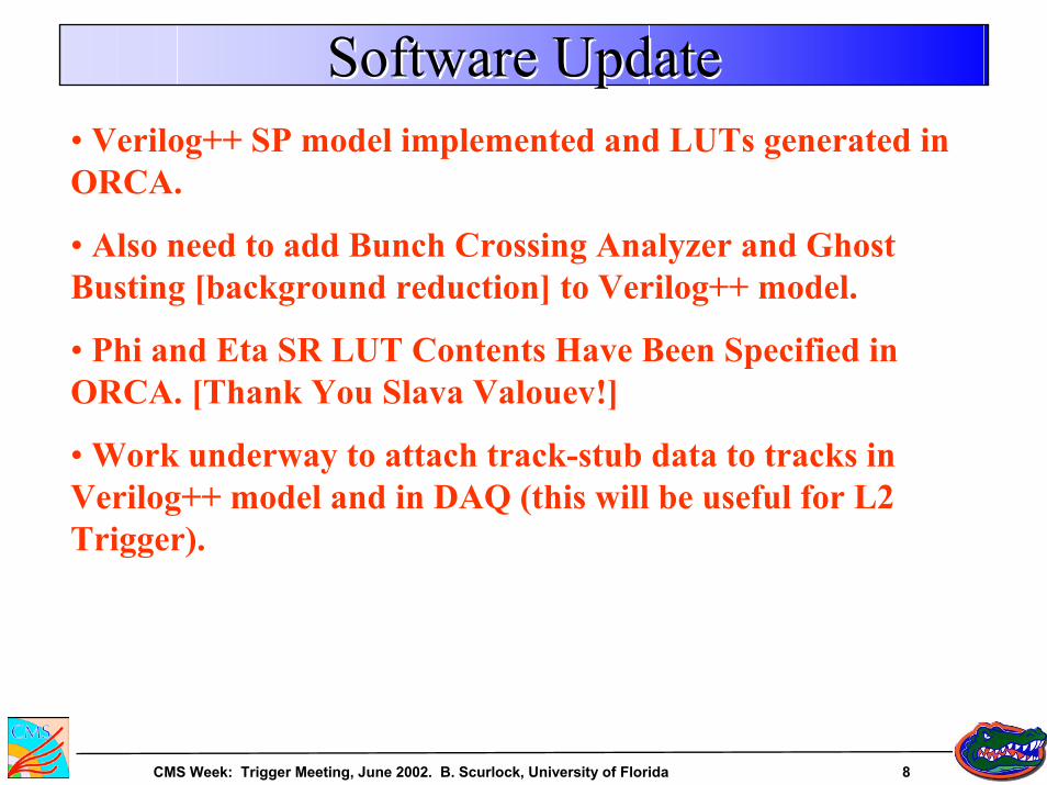
Software UpdateSoftware UpdateSoftware Update• Verilog++ SP model implemented and LUTs generated in ORCA.
• Also need to add Bunch Crossing Analyzer and Ghost Busting [background reduction] to Verilog++ model.
• Phi and Eta SR LUT Contents Have Been Specified in ORCA. [Thank You Slava Valouev!]
• Work underway to attach track-stub data to tracks in Verilog++ model and in DAQ (this will be useful for L2 Trigger).
CMS Week: Trigger Meeting, June 2002. B. Scurlock, University of Florida 9
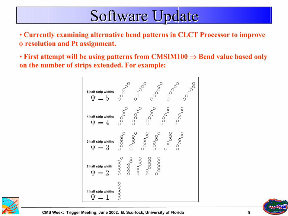
Software UpdateSoftware UpdateSoftware Update• Currently examining alternative bend patterns in CLCT Processor to improve φ resolution and Pt assignment.
• First attempt will be using patterns from CMSIM100 ⇒ Bend value based only on the number of strips extended. For example:
CMS Week: Trigger Meeting, June 2002. B. Scurlock, University of Florida 10
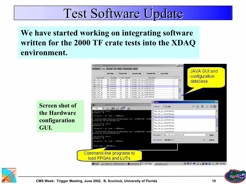
Test Software UpdateTest Software UpdateTest Software UpdateWe have started working on integrating software written for the 2000 TF crate tests into the XDAQ environment.
Screen shot of the Hardware configuration GUI.
CMS Week: Trigger Meeting, June 2002. B. Scurlock, University of Florida 11
ScheduleScheduleSchedule• November 2002: expect to finish the SP protoype. Will conduct single board tests
• MPC→SR/SP tests will continue through to 4/30/03.
• 5/1/03 to 9/30/03: Plan chain tests with CSC chambers and front-end electronics using cosmic rays and test beam.
• Also plan to do DT↔CSC tests sometime after May 1 2003.
CMS Week: Trigger Meeting, June 2002. B. Scurlock, University of Florida 12
ConclusionsConclusionsConclusions• CSC TF Backplane Specified
• DT-CSC Interface Specified
• SR/SP Schematics Complete
• SR/SP Layout Started
• SR LUT Generation Completed in ORCA
• More Additions Scheduled for Verilog++ SP Model
• Work on φb Definition in Progress