Embed Size (px)
Citation preview
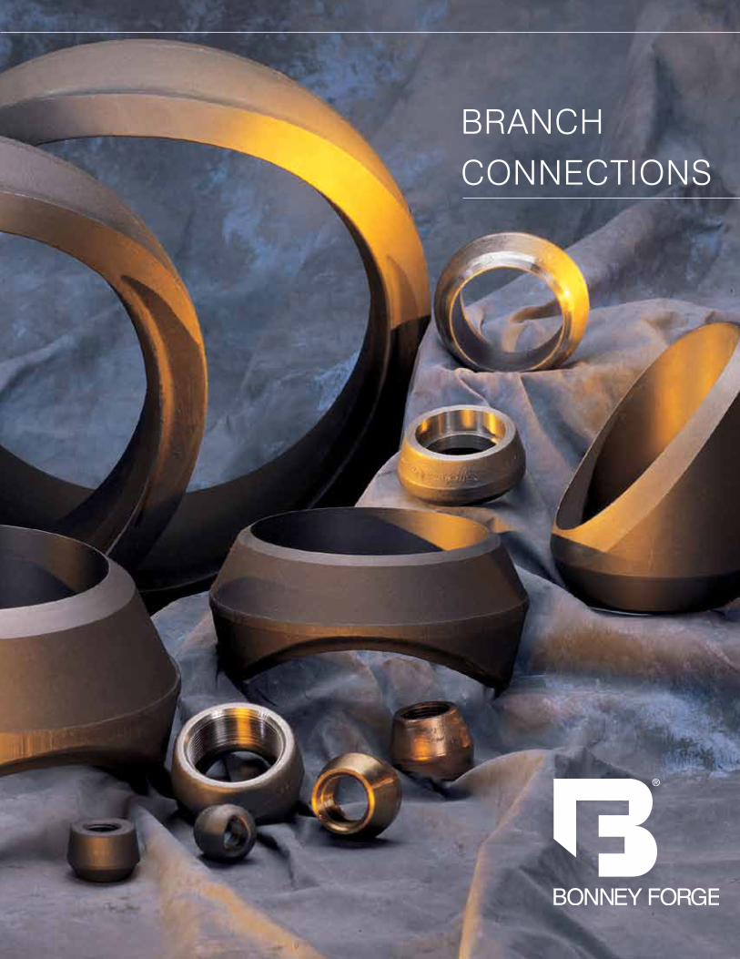
BRANCH CONNECTIONS

, Weldolet®, Thredolet®, Sockolet®, Flexolet™, Latrolet®, Elbolet®, Sweepolet®, Insert Weldolet®, Nipolet®, Brazolet®, and Coupolet™, are trademarks registered for the exclusive use of Bonney Forge Corporation.
SaleS Center/WarehouSe 14496 Croghan Pike
P.o. Box 330 Mt. union, Pa 17066
(814) 542-2545 • (800) 231-0655 (800) 345-7546 • Fax (814) 542-9977
www.bonneyforge.come-mail: [email protected]
Table Of Contents
The Bonney Forge Std. Wt. Weldolet®, CL3000 Sockolet ®, CL3000 Thredolet ® (1/8" through 6" outlet size) and Coupolet™ bear the UL symbol indicating Underwriters Laboratories listing of these fittings for use in sprinkler systems and other fire protection water supply systems.
When to use Weldolets® .......................................................................... 4,5
Quality Control ............................................................................................ 6
How to Order and Specify Branch Connections ............................................ 7
Weldolet® .............................................................................................. 8-14
Standard ........................................................................................ 8,9
Extra Strong ............................................................................... 10,11
Schedule 160/xx Strong ............................................................. 12,13
heavy Wall ...................................................................................... 14
Thredolet® and Sockolet® .................................................................... 15,16
Flexolet™ Sa/a105 & Sa/a350 LF2 CL1
Butt-Welding, Threaded, Socket Welding ..................................... 17-19
Flexolet™ Stainless and alloy ............................................................... 20-22
Flexolet™ S5s/10s & CL 300 Light Weight ................................................. 23
Latrolet® and Elbolet® ......................................................................... 24, 25
Sweepolet® ........................................................................................ 26, 27
Insert Weldolet® ....................................................................................... 28
Nipolet® ................................................................................................... 29
Brazolet® ................................................................................................. 30
Coupolet™ ................................................................................................ 31
Engineering Specifications .................................................................... 32-40
Conventional Olet® Run Size Combination Charts ............................. 38
Flexolet™ Run Size Combination Charts........................................ 39-40
In 1943 when Bonney Forge pioneered
the “Shape of Reinforcement” for
branch connections, who would have
thought it would fast become a recog-
nized industry standard. Today, Bon-
ney Forge Branch Connections offer
complete run pipe reinforcement while
avoiding cracks, fillet welds, and sharp
re-entrant corner reinforcement taper-
ing at the sides, thus preventing abrupt
changes in thickness where the fitting
joins the header pipe.
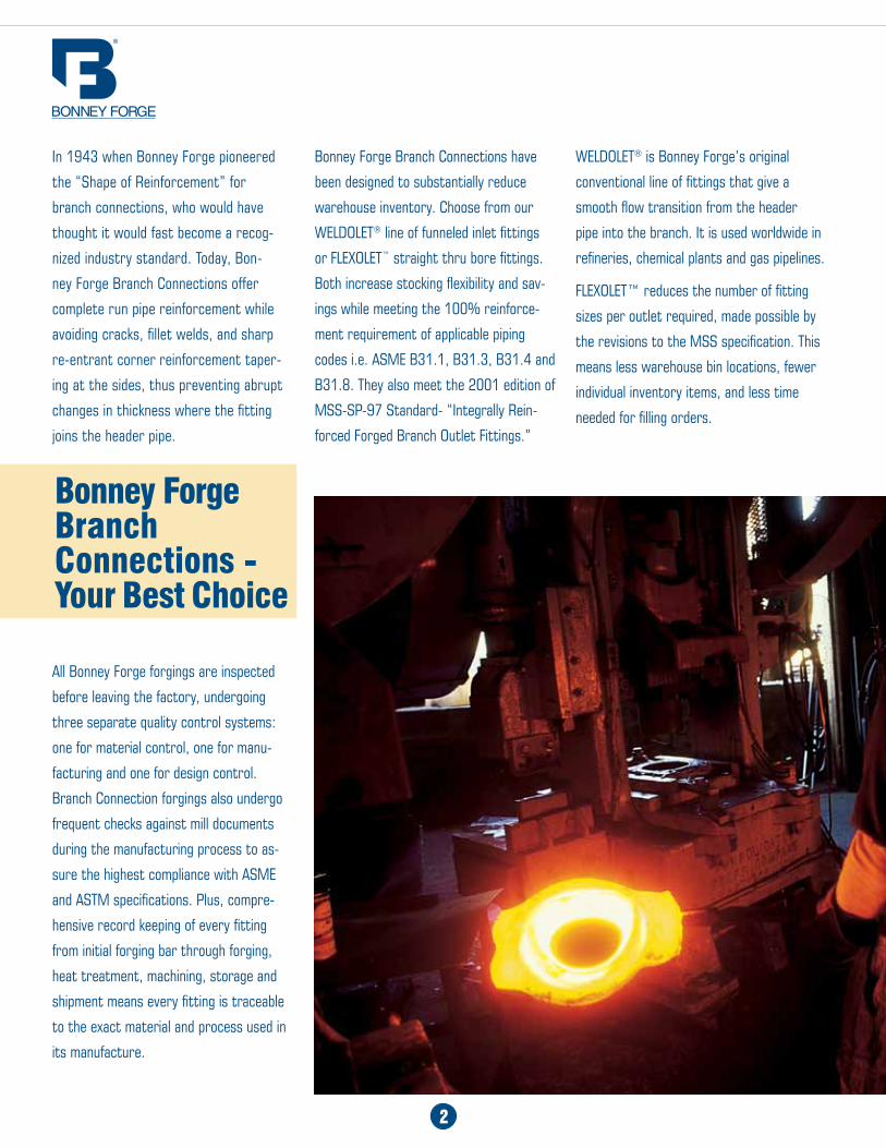
All Bonney Forge forgings are inspected
before leaving the factory, undergoing
three separate quality control systems:
one for material control, one for manu-
facturing and one for design control.
Branch Connection forgings also undergo
frequent checks against mill documents
during the manufacturing process to as-
sure the highest compliance with ASME
and ASTM specifications. Plus, compre-
hensive record keeping of every fitting
from initial forging bar through forging,
heat treatment, machining, storage and
shipment means every fitting is traceable
to the exact material and process used in
its manufacture.
2
Bonney Forge Branch Connections - Your Best Choice
Bonney Forge Branch Connections have
been designed to substantially reduce
warehouse inventory. Choose from our
WELDOLET® line of funneled inlet fittings
or FLEXOLET™ straight thru bore fittings.
Both increase stocking flexibility and sav-
ings while meeting the 100% reinforce-
ment requirement of applicable piping
codes i.e. ASME B31.1, B31.3, B31.4 and
B31.8. They also meet the 2001 edition of
MSS-SP-97 Standard- “Integrally Rein-
forced Forged Branch Outlet Fittings.”
WELDOLET® is Bonney Forge’s original
conventional line of fittings that give a
smooth flow transition from the header
pipe into the branch. It is used worldwide in
refineries, chemical plants and gas pipelines.
FLEXOLET™ reduces the number of fitting
sizes per outlet required, made possible by
the revisions to the MSS specification. This
means less warehouse bin locations, fewer
individual inventory items, and less time
needed for filling orders.

3
4
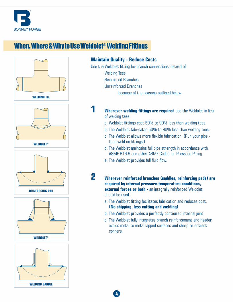
Maintain Quality - Reduce CostsUse the Weldolet fitting for branch connections instead of Welding Tees Reinforced Branches Unreinforced Branches because of the reasons outlined below:
1 Wherever welding fittings are required use the Weldolet in lieu of welding tees. a. Weldolet fittings cost 50% to 90% less than welding tees. b. The Weldolet fabricates 50% to 90% less than welding tees. c. The Weldolet allows more flexible fabrication. (Run your pipe - then weld on fittings.) d. The Weldolet maintains full pipe strength in accordance with ASME B16.9 and other ASME Codes for Pressure Piping. e. The Weldolet provides full fluid flow.
2 Wherever reinforced branches (saddles, reinforcing pads) are required by internal pressure-temperature conditions, external forces or both - an integrally reinforced Weldolet should be used. a. The Weldolet fitting facilitates fabrication and reduces cost. (No chipping, less cutting and welding) b. The Weldolet provides a perfectly contoured internal joint. c. The Weldolet fully integrates branch reinforcement and header, avoids metal to metal lapped surfaces and sharp re-entrant corners.
When, Where & Why to Use Weldolet® Welding Fittings
WELdINg TEE
WELdoLET®
REINFoRCINg Pad
WELdoLET®
WELdINg SaddLE
5
When, Where & Why to Use Weldolet® Welding Fittings
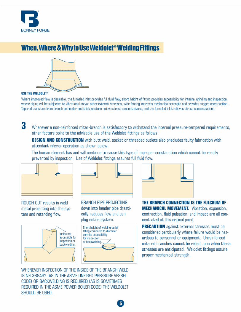
3 Wherever a non-reinforced miter-branch is satisfactory to withstand the internal pressure-tempered requirements, other factors point to the advisable use of the Weldolet fittings as follows:
dESIgN aNd CoNSTRUCTIoN with butt weld, socket or threaded outlets also precludes faulty fabrication with attendant inferior operation as shown below: The human element has and will continue to cause this type of improper construction which cannot be readily prevented by inspection. Use of Weldolet fittings assures full fluid flow.
ROUGH CUT results in weld metal projecting into the sys-tem and retarding flow.
BRANCH PIPE PROJECTING down into header pipe drasti-cally reduces flow and can plug entire system.
THE BRaNCH CoNNECTIoN IS THE FULCRUM oF MECHaNICaL MoVEMENT. Vibration, expansion, contraction, fluid pulsation, and impact are all con-centrated at this critical point.PRECaUTIoN against external stresses must be considered particularly where failure would be haz-ardous to personnel or equipment. Unreinforced mitered branches cannot be relied upon when these stresses are anticipated. Weldolet fittings assure proper mechanical strength.
WHENEVER INSPECTION OF THE INSIDE OF THE BRANCH WELD IS NECESSARY (AS IN THE ASME UNFIRED PRESSURE VESSEL CODE) OR BACKWELDING IS REQUIRED (AS IS SOMETIMES REQUIRED IN THE ASME POWER BOILER CODE) THE WELDOLET SHOULD BE USED.
USE THE WELdoLET®
Where improved flow is desirable, the funneled inlet provides full fluid flow, short height of fitting provides accessibility for internal grinding and inspection, where piping will be subjected to vibrational and/or other external stresses, wide footing improves mechanical strength and provides rugged construction. Tapered transition from branch to header and thick juncture relieve stress concentrations, and the funneled inlet relieves stress concentrations.
Inside not accessible for inspection or backwelding.
Short height of welding outlet fitting compared to diameter permits accessibility for inspection or backwelding.
Bonney Forge craftsmanship is combined with rigid quality control systems to provide complete assurance of the highest manufacturing standards and compliance with applicable ASME and ASTM specifications. Every fitting manufactured is subjected to three separate quality control systems: one for material control, one for manufacturing control, and one for design control.
All forgings are inspected before being passed to the shipping room. Frequent analyses are made to check against mill documents. Accurate records are kept of every fitting, from initial forging bar through forging, heat treatment, machining, storage and shipment. Every single fitting is traceable to the exact material and process used in its manufacture.
Rather than blindly following the results of tests on branch connections by others and applying them to the Weldolet®, Bonney Forge performed the necessary basic research and applied it directly to the Weldolet® and Sweepolet® type of construction. By ultra-precise use of stress coat, monitored by strain gauges, Bonney Forge has obtained the effect of an infinite number of strain gauges. Starting with unreinforced branch connections, and testing a large number of sizes, size combinations and weights, Bonney Forge scientifically observed and developed patterns of the areas of stress concentrations as well as the areas having less than an average stress.
As a result of a continuing program of testing over the years, the Weldolet and the Sweepolet have undergone design revisions to keep pace with the changing needs of the piping industry. The most modern research techniques are used including stress analyses by means of three-dimensional photoelasticity. The modern Weldolet and Sweepolet provides the best engineered method of fabricating a branch connection of carbon steel, stainless, alloy and high yield transmission pipe, in all pipe wall thicknesses. The Sweepolet is the recommended branch connection for Class I (critical service) nuclear piping.
THE WELDOLET PROVIDES 100% PIPE STRENGTH FOR ALL SIZES, WEIGHTS AND SCHEDULES.Weldolet Welding Fittings are rated the same as seamless steel pipe. These ratings are based on the ASME Codes for Pressure Piping. For example, an extra strong Weldolet used on extra strong pipe of the equivalent material provides 100% pipe strength. Likewise, a standard weight Weldolet has the same ratings as standard weight pipe and provides 100% pipe strength when used on standard weight pipe.
Weldolet Welding Fittings are manufactured according to the requirements of the ASME B16.9 Standard for Steel Butt-Welding Fittings. Weldolets are designed so that their actual bursting strength when installed as recommended exceeds the computed bursting strength of the pipe of the designated weight or schedule number and material. Header assemblies with full size and reducing branches constructed with Weldolet welding fittings tested in accordance with the provisions of ASME B16.9 in all cases burst in the header pipe well above the computed minimum bursting strength of the straight run of unpenetrated pipe.
Quality Control
Research
Temperature - Pressure Ratings
6
7
How To Order Branch Connections3. Indicate Class or Schedule/Pipe Wall • Class 3000, 6000 - Threaded or Socket-weld • STD, XSTG, S160, etc. - Butt-welded4. Select Material • Carbon Steel - SA/A105, SA/A105N - SA/A350-LF2, etc. • Stainless Steels • Other5. Specify design Code (if available)
Examples - Quantity - Description - Material 10 pieces - 8 x 4 Weldolet® - STD Wt. SA/A105 5 pieces - 36 - 6 x 1-1/2 Flexolet™ - 3M Threaded - SA/A105
Generally the schedules of the run pipe and branch pipe are identical and thus specification of the equivalent schedule Weldolet assures the proper fitting being used.
Example:
16" Standard weight x 6" Standard weight is specified as a 6" standard weight fitting.
Where the schedule of the run is greater or less than the schedule of the branch, it is essential that both schedules be specified since (a) The Weldolet’s rein-forcing characteristics are a function of the run pipe wall thickness, which in turn designates the schedule of the basic Weldolet® fitting to be used; (b) The wall thickness of the outlet or branch end must match the wall thickness of the branch pipe.
Example:
16" Extra strong x 6" Standard weight
16" Standard weight x 6" Extra strong
Special care is suggested to avoid confusing schedule 40 and standard weight as being identical (above 10" schedule 40 is heavier) and schedule 80 and extra strong (above 8" schedule 80 is heavier).
Example:
8" Schedule 80 x 4" Schedule 80 fitting or extra strong fitting. 18" Schedule 80 x 4" Schedule 80 is a considerably heavier fitting, because the reinforcement is for 18" schedule 80 pipe with a wall thickness of approximately 1".
The Weldolet® is available in standard code designs for all combinations of run wall thicknesses up through 3 1/2" thickness and branch wall thicknesses up through double extra strong. Designs for thicknesses greater than these can be developed on request.
When run size is standard weight and the branch is standard weight - specify as standard weight. When run is standard weight and branch size is bored for a schedule less than standard weight - specify and price as standard weight plus special bore. When run size is extra strong weight and the branch is extra strong weight - specify and price as extra strong. When run size is extra strong weight and the branch is bored for a schedule less than extra strong weight - specify as extra strong plus special bore. When run size is schedule 160 weight and the branch is schedule 160 weight - specify and price as schedule 160. When the run size is schedule 160 weight and the branch is bored for a schedule less than schedule 160 - specify as schedule 160 plus special bore. For 12" and larger run sizes with wall thicknesses heavier than schedule 160 - specify Heavy Wall Weldolets as shown on page 14.
When ordering include the following information:
Examples:
Quantity Size description Material
30 6 x 6 Weldolet®, Standard Weight Carbon Steel
2 16 x 4 Weldolet® Sch 100 x Sch 40 F22
30 2 x 2 Sockolet® Class 3000 304 S.S.
25 10-3 x 3/4 Thredolet® Class 6000 Carbon Steel
Note - Material of Olet™ Fittings should be the same as material of header.
How To Specify Bonney Forge Branch Connections
How to Specify Bonney Forge Branch Connections With Special Bores
1. Specify Size • Outlet size • Run or Header (or Run Size Combination, see pages 38 - 40)2. Specify Style olet®
• Butt-weld (Weldolet®) • Threaded (Thredolet®) • Socket-weld (Sockolet®) • Other (Elbolet®, Latrolet®, Sweepolet®, Insert Weldolet®, Nipolet®, etc.) Flexolet™ • Buttweld • Threaded • Socket-weld
8
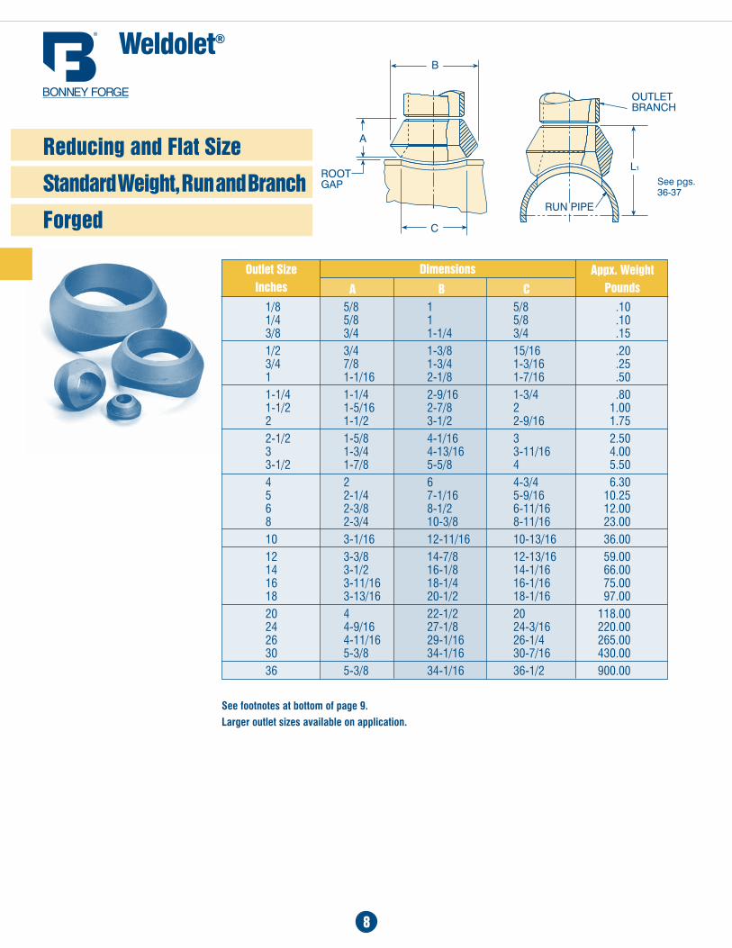
1/8 5/8 1 5/8 .10 1/4 5/8 1 5/8 .10 3/8 3/4 1-1/4 3/4 .151/2 3/4 1-3/8 15/16 .20 3/4 7/8 1-3/4 1-3/16 .25 1 1-1/16 2-1/8 1-7/16 .501-1/4 1-1/4 2-9/16 1-3/4 .80 1-1/2 1-5/16 2-7/8 2 1.00 2 1-1/2 3-1/2 2-9/16 1.752-1/2 1-5/8 4-1/16 3 2.50 3 1-3/4 4-13/16 3-11/16 4.00 3-1/2 1-7/8 5-5/8 4 5.504 2 6 4-3/4 6.30 5 2-1/4 7-1/16 5-9/16 10.25 6 2-3/8 8-1/2 6-11/16 12.00 8 2-3/4 10-3/8 8-11/16 23.0010 3-1/16 12-11/16 10-13/16 36.0012 3-3/8 14-7/8 12-13/16 59.00 14 3-1/2 16-1/8 14-1/16 66.00 16 3-11/16 18-1/4 16-1/16 75.00 18 3-13/16 20-1/2 18-1/16 97.0020 4 22-1/2 20 118.00 24 4-9/16 27-1/8 24-3/16 220.00 26 4-11/16 29-1/16 26-1/4 265.00 30 5-3/8 34-1/16 30-7/16 430.0036 5-3/8 34-1/16 36-1/2 900.00
Dimensions
a B C
See footnotes at bottom of page 9.
Larger outlet sizes available on application.
Outlet SizeInches
appx. WeightPounds
Reducing and Flat Size
Standard Weight, Run and Branch
Forged
Weldolet®
See pgs. 36-37
Weldolet®
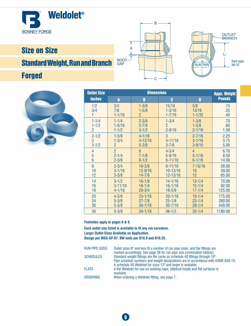
9
Footnotes apply to pages 8 & 9.
Each outlet size listed is available to fit any run curvature. Larger Outlet Sizes Available on Application. Design per MSS-SP-97. BW ends per B16.9 and B16.25.
run PiPe SizeS Outlet sizes 6" and less fit a number of run pipe sizes, and the fittings are marked accordingly. See page 38 for run pipe size combination table(s).SCheduleS Standard weight fittings are the same as schedule 40 fittings through 10". Pipe schedule numbers and weight designations are in accordance with aSME B36.10. a schedule 40 Weldolet for sizes 12" and larger is available.FLaTS a flat Weldolet for use on welding caps, elliptical heads and flat surfaces is available.ordering When ordering a Weldolet fitting, see page 7.
1/2 3/4 1-3/8 15/16 5/8 .15 3/4 7/8 1-5/8 1-3/16 13/16 .25 1 1-1/16 2 1-7/16 1-1/32 .401-1/4 1-1/4 2-3/8 1-3/4 1-3/8 .70 1-1/2 1-5/16 2-7/8 2 1-5/8 .80 2 1-1/2 3-1/2 2-9/16 2-1/16 1.502-1/2 1-5/8 4-1/16 3 2-7/16 2.25 3 1-3/4 4-13/16 3-11/16 3-1/16 3.75 3-1/2 2 5-3/8 3-7/8 3-9/16 5.004 2 6 4-3/4 4 6.70 5 2-1/4 7-1/8 5-9/16 5-1/16 8.50 6 2-3/8 8-1/2 6-11/16 6-1/16 14.008 2-3/4 10-3/8 8-11/16 7-15/16 28.00 10 3-1/16 12-9/16 10-13/16 10 39.00 12 3-3/8 14-7/8 12-13/16 12 65.0014 3-1/2 16-1/8 14-1/16 13-1/4 70.00 16 3-11/16 18-1/4 16-1/16 15-1/4 92.00 18 4-1/16 20-3/4 18-5/8 17-1/4 125.0020 4-5/8 23-1/16 20-1/16 19-1/4 175.00 24 5-3/8 27-7/8 25-1/8 23-1/4 280.00 30 5-3/8 34-1/16 30-7/16 29-1/4 440.0036 5-3/8 34-1/16 36-1/2 35-1/4 1180.00
DimensionsOutlet SizeInches
appx. Weight Pounds
Size on Size
Standard Weight, Run and Branch
Forged
a B C D
See pgs. 36-37
10
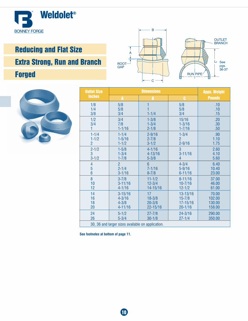
Weldolet®
1/8 5/8 1 5/8 .10 1/4 5/8 1 5/8 .10 3/8 3/4 1-1/4 3/4 .151/2 3/4 1-3/8 15/16 .20 3/4 7/8 1-3/4 1-3/16 .30 1 1-1/16 2-1/8 1-7/16 .501-1/4 1-1/4 2-9/16 1-3/4 .90 1-1/2 1-5/16 2-7/8 2 1.10 2 1-1/2 3-1/2 2-9/16 1.752-1/2 1-5/8 4-1/16 3 2.60 3 1-3/4 4-13/16 3-11/16 4.10 3-1/2 1-7/8 5-3/8 4 5.604 2 6 4-3/4 6.40 5 2-1/4 7-1/16 5-9/16 10.40 6 3-1/16 8-7/8 6-11/16 23.008 3-7/8 11-1/2 8-11/16 37.00 10 3-11/16 12-3/4 10-7/16 46.00 12 4-1/16 14-15/16 12-1/2 61.0014 3-15/16 17 13-13/16 70.00 16 4-3/16 18-3/8 15-7/8 102.00 18 4-3/8 20-3/8 17-15/16 130.00 20 4-11/16 22-15/16 20-1/16 158.00
24 5-1/2 27-7/8 24-3/16 290.00 26 5-3/4 30-1/8 27-1/4 350.0030, 36 and larger sizes available on application.
Dimensions
a B C
appx. WeightPounds
Outlet Size Inches
See footnotes at bottom of page 11.
Reducing and Flat Size
Extra Strong, Run and Branch
Forged
See pgs. 36-37
11
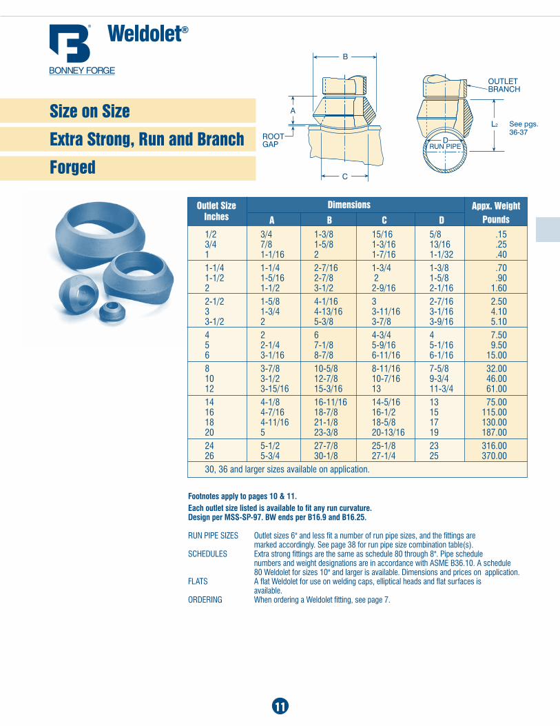
Weldolet®
Dimensions
a B C D appx. Weight
PoundsOutlet Size
Inches
Footnotes apply to pages 10 & 11. Each outlet size listed is available to fit any run curvature. Design per MSS-SP-97. BW ends per B16.9 and B16.25.
run PiPe SizeS Outlet sizes 6" and less fit a number of run pipe sizes, and the fittings are marked accordingly. See page 38 for run pipe size combination table(s).SCheduleS Extra strong fittings are the same as schedule 80 through 8". Pipe schedule numbers and weight designations are in accordance with aSME B36.10. a schedule 80 Weldolet for sizes 10" and larger is available. Dimensions and prices on application.FLaTS a flat Weldolet for use on welding caps, elliptical heads and flat surfaces is available.ordering When ordering a Weldolet fitting, see page 7.
Size on Size
Extra Strong, Run and Branch
Forged
1/2 3/4 1-3/8 15/16 5/8 .15 3/4 7/8 1-5/8 1-3/16 13/16 .25 1 1-1/16 2 1-7/16 1-1/32 .401-1/4 1-1/4 2-7/16 1-3/4 1-3/8 .70 1-1/2 1-5/16 2-7/8 2 1-5/8 .90 2 1-1/2 3-1/2 2-9/16 2-1/16 1.602-1/2 1-5/8 4-1/16 3 2-7/16 2.50 3 1-3/4 4-13/16 3-11/16 3-1/16 4.10 3-1/2 2 5-3/8 3-7/8 3-9/16 5.104 2 6 4-3/4 4 7.50 5 2-1/4 7-1/8 5-9/16 5-1/16 9.50 6 3-1/16 8-7/8 6-11/16 6-1/16 15.008 3-7/8 10-5/8 8-11/16 7-5/8 32.00 10 3-1/2 12-7/8 10-7/16 9-3/4 46.00 12 3-15/16 15-3/16 13 11-3/4 61.0014 4-1/8 16-11/16 14-5/16 13 75.00 16 4-7/16 18-7/8 16-1/2 15 115.00 18 4-11/16 21-1/8 18-5/8 17 130.00 20 5 23-3/8 20-13/16 19 187.0024 5-1/2 27-7/8 25-1/8 23 316.00 26 5-3/4 30-1/8 27-1/4 25 370.0030, 36 and larger sizes available on application.
See pgs. 36-37
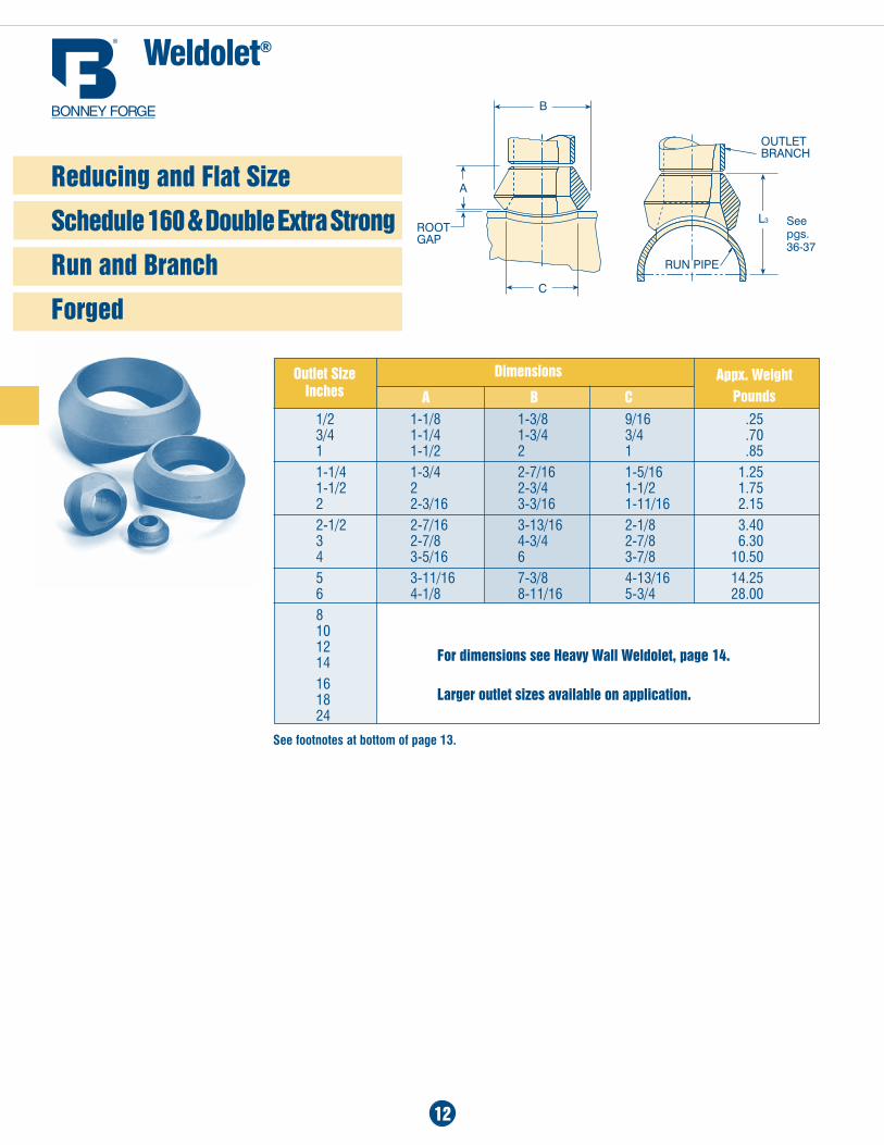
1/2 1-1/8 1-3/8 9/16 .25 3/4 1-1/4 1-3/4 3/4 .70 1 1-1/2 2 1 .851-1/4 1-3/4 2-7/16 1-5/16 1.25 1-1/2 2 2-3/4 1-1/2 1.75 2 2-3/16 3-3/16 1-11/16 2.152-1/2 2-7/16 3-13/16 2-1/8 3.40 3 2-7/8 4-3/4 2-7/8 6.30 4 3-5/16 6 3-7/8 10.505 3-11/16 7-3/8 4-13/16 14.25 6 4-1/8 8-11/16 5-3/4 28.008 10 12 1416 18 24
Weldolet®
For dimensions see Heavy Wall Weldolet, page 14.
Larger outlet sizes available on application.
Dimensions
a B C appx. Weight
PoundsOutlet Size
Inches
12
Reducing and Flat Size
Schedule 160 & Double Extra Strong
Run and Branch
Forged
See footnotes at bottom of page 13.
See pgs. 36-37
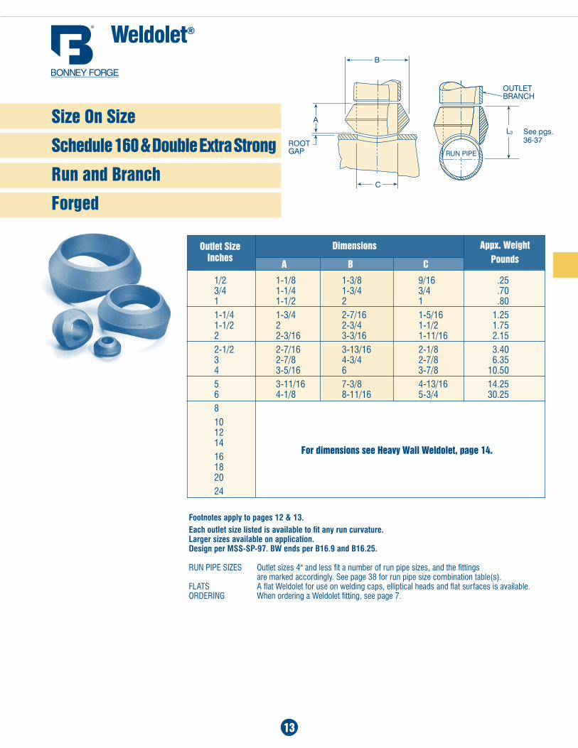
1/2 1-1/8 1-3/8 9/16 .25 3/4 1-1/4 1-3/4 3/4 .70 1 1-1/2 2 1 .801-1/4 1-3/4 2-7/16 1-5/16 1.25 1-1/2 2 2-3/4 1-1/2 1.75 2 2-3/16 3-3/16 1-11/16 2.152-1/2 2-7/16 3-13/16 2-1/8 3.40 3 2-7/8 4-3/4 2-7/8 6.35 4 3-5/16 6 3-7/8 10.505 3-11/16 7-3/8 4-13/16 14.25 6 4-1/8 8-11/16 5-3/4 30.258 10 12 1416 18 2024
Footnotes apply to pages 12 & 13.Each outlet size listed is available to fit any run curvature. Larger sizes available on application. Design per MSS-SP-97. BW ends per B16.9 and B16.25.
run PiPe SizeS Outlet sizes 4" and less fit a number of run pipe sizes, and the fittings are marked accordingly. See page 38 for run pipe size combination table(s).FLaTS a flat Weldolet for use on welding caps, elliptical heads and flat surfaces is available.ordering When ordering a Weldolet fitting, see page 7.
For dimensions see Heavy Wall Weldolet, page 14.
Dimensions
a B C
appx. WeightPounds
Outlet Size Inches
Size On Size
Schedule 160 & Double Extra Strong
Run and Branch
Forged
Weldolet®
13
See pgs. 36-37
14
Weldolet®
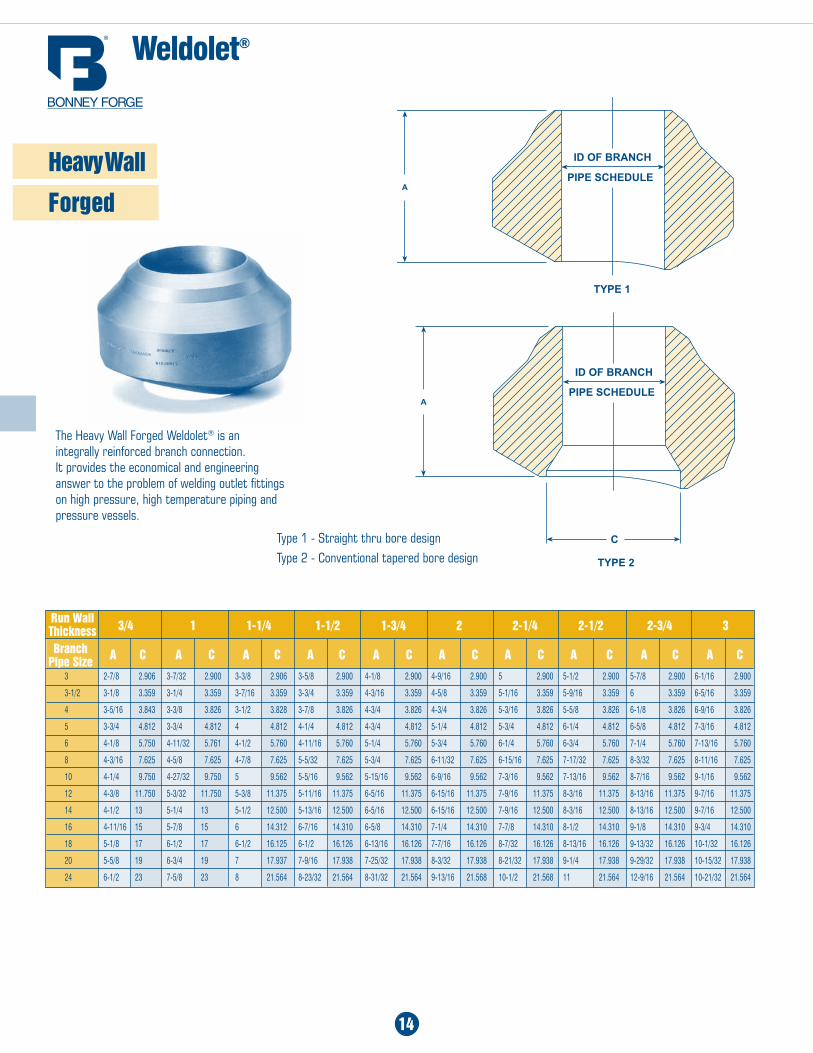
3 2-7/8 2.906 3-7/32 2.900 3-3/8 2.906 3-5/8 2.900 4-1/8 2.900 4-9/16 2.900 5 2.900 5-1/2 2.900 5-7/8 2.900 6-1/16 2.900
3-1/2 3-1/8 3.359 3-1/4 3.359 3-7/16 3.359 3-3/4 3.359 4-3/16 3.359 4-5/8 3.359 5-1/16 3.359 5-9/16 3.359 6 3.359 6-5/16 3.359
4 3-5/16 3.843 3-3/8 3.826 3-1/2 3.828 3-7/8 3.826 4-3/4 3.826 4-3/4 3.826 5-3/16 3.826 5-5/8 3.826 6-1/8 3.826 6-9/16 3.826
5 3-3/4 4.812 3-3/4 4.812 4 4.812 4-1/4 4.812 4-3/4 4.812 5-1/4 4.812 5-3/4 4.812 6-1/4 4.812 6-5/8 4.812 7-3/16 4.812
6 4-1/8 5.750 4-11/32 5.761 4-1/2 5.760 4-11/16 5.760 5-1/4 5.760 5-3/4 5.760 6-1/4 5.760 6-3/4 5.760 7-1/4 5.760 7-13/16 5.760
8 4-3/16 7.625 4-5/8 7.625 4-7/8 7.625 5-5/32 7.625 5-3/4 7.625 6-11/32 7.625 6-15/16 7.625 7-17/32 7.625 8-3/32 7.625 8-11/16 7.625
10 4-1/4 9.750 4-27/32 9.750 5 9.562 5-5/16 9.562 5-15/16 9.562 6-9/16 9.562 7-3/16 9.562 7-13/16 9.562 8-7/16 9.562 9-1/16 9.562
12 4-3/8 11.750 5-3/32 11.750 5-3/8 11.375 5-11/16 11.375 6-5/16 11.375 6-15/16 11.375 7-9/16 11.375 8-3/16 11.375 8-13/16 11.375 9-7/16 11.375
14 4-1/2 13 5-1/4 13 5-1/2 12.500 5-13/16 12.500 6-5/16 12.500 6-15/16 12.500 7-9/16 12.500 8-3/16 12.500 8-13/16 12.500 9-7/16 12.500
16 4-11/16 15 5-7/8 15 6 14.312 6-7/16 14.310 6-5/8 14.310 7-1/4 14.310 7-7/8 14.310 8-1/2 14.310 9-1/8 14.310 9-3/4 14.310
18 5-1/8 17 6-1/2 17 6-1/2 16.125 6-1/2 16.126 6-13/16 16.126 7-7/16 16.126 8-7/32 16.126 8-13/16 16.126 9-13/32 16.126 10-1/32 16.126
20 5-5/8 19 6-3/4 19 7 17.937 7-9/16 17.938 7-25/32 17.938 8-3/32 17.938 8-21/32 17.938 9-1/4 17.938 9-29/32 17.938 10-15/32 17.938
24 6-1/2 23 7-5/8 23 8 21.564 8-23/32 21.564 8-31/32 21.564 9-13/16 21.568 10-1/2 21.568 11 21.564 12-9/16 21.564 10-21/32 21.564
3/4 1 1-1/4 1-1/2 1-3/4 2 2-1/4 2-1/2 2-3/4 3
Branch Pipe Size a C a C a C a C a C a C a C a C a C a C
Run Wall Thickness
The Heavy Wall Forged Weldolet® is an integrally reinforced branch connection. It provides the economical and engineering answer to the problem of welding outlet fittings on high pressure, high temperature piping and pressure vessels.
Type 1 - Straight thru bore designType 2 - Conventional tapered bore design
Heavy Wall
Forged
15
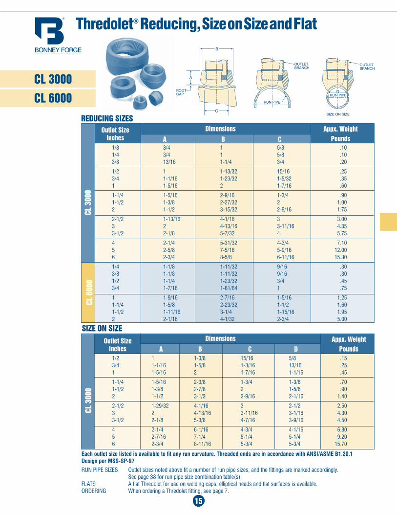
CL 3000
CL 6000
Thredolet® Reducing, Size on Size and Flat
REDUCIng SIzES
1/8 3/4 1 5/8 .10 1/4 3/4 1 5/8 .10 3/8 13/16 1-1/4 3/4 .20
1/2 1 1-13/32 15/16 .25 3/4 1-1/16 1-23/32 1-5/32 .35 1 1-5/16 2 1-7/16 .60
1-1/4 1-5/16 2-9/16 1-3/4 .90 1-1/2 1-3/8 2-27/32 2 1.00 2 1-1/2 3-15/32 2-9/16 1.75
2-1/2 1-13/16 4-1/16 3 3.00 3 2 4-13/16 3-11/16 4.35 3-1/2 2-1/8 5-7/32 4 5.75
4 2-1/4 5-31/32 4-3/4 7.10 5 2-5/8 7-5/16 5-9/16 12.00 6 2-3/4 8-5/8 6-11/16 15.30
1/4 1-1/8 1-11/32 9/16 .30 3/8 1-1/8 1-11/32 9/16 .30 1/2 1-1/4 1-23/32 3/4 .45 3/4 1-7/16 1-61/64 1 .75
1 1-9/16 2-7/16 1-5/16 1.25 1-1/4 1-5/8 2-23/32 1-1/2 1.60 1-1/2 1-11/16 3-1/4 1-15/16 1.95 2 2-1/16 4-1/32 2-3/4 5.00
1/2 1 1-3/8 15/16 5/8 .15 3/4 1-1/16 1-5/8 1-3/16 13/16 .25 1 1-5/16 2 1-7/16 1-1/16 .45
1-1/4 1-5/16 2-3/8 1-3/4 1-3/8 .70 1-1/2 1-3/8 2-7/8 2 1-5/8 .90 2 1-1/2 3-1/2 2-9/16 2-1/16 1.40
2-1/2 1-29/32 4-1/16 3 2-1/2 2.50 3 2 4-13/16 3-11/16 3-1/16 4.30 3-1/2 2-1/8 5-3/8 4-7/16 3-9/16 4.50
4 2-1/4 6-1/16 4-3/4 4-1/16 6.80 5 2-7/16 7-1/4 5-1/4 5-1/4 9.20 6 2-3/4 8-11/16 5-3/4 5-3/4 15.70
CL 3
000
SIzE On SIzE
a B C D appx. Weight
PoundsOutlet Size
Inches
Dimensions
Dimensions
a B C appx. Weight
PoundsOutlet Size
Inches
CL 3
000
CL 6
000
Each outlet size listed is available to fit any run curvature. Threaded ends are in accordance with ANSI/ASME B1.20.1 Design per MSS-SP-97
run PiPe SizeS Outlet sizes noted above fit a number of run pipe sizes, and the fittings are marked accordingly. See page 38 for run pipe size combination table(s).FLaTS a flat Thredolet for use on welding caps, elliptical heads and flat surfaces is available.ORDERING When ordering a Thredolet fitting, see page 7.
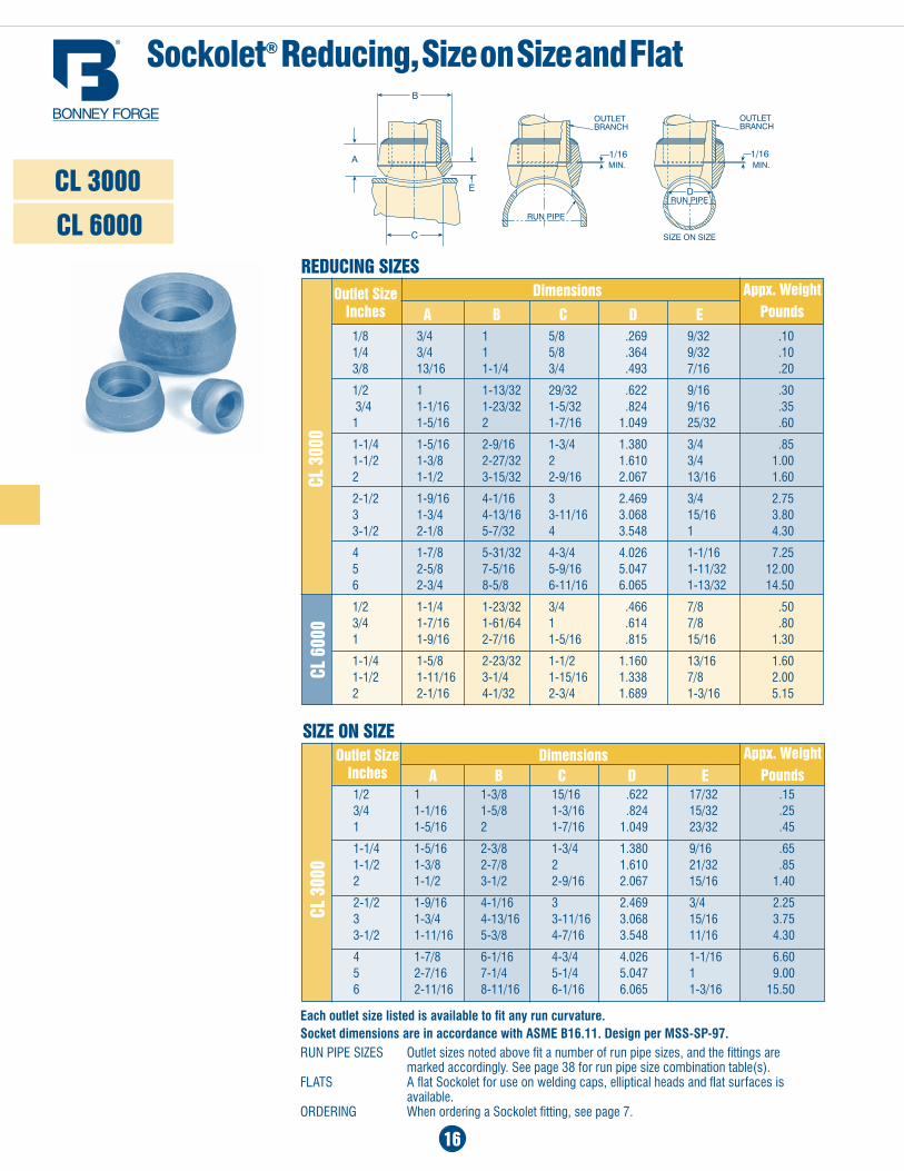
Sockolet® Reducing, Size on Size and Flat
Each outlet size listed is available to fit any run curvature. Socket dimensions are in accordance with ASME B16.11. Design per MSS-SP-97.run PiPe SizeS Outlet sizes noted above fit a number of run pipe sizes, and the fittings are marked accordingly. See page 38 for run pipe size combination table(s).FLaTS a flat Sockolet for use on welding caps, elliptical heads and flat surfaces is available.ORDERING When ordering a Sockolet fitting, see page 7.
1/8 3/4 1 5/8 .269 9/32 .10 1/4 3/4 1 5/8 .364 9/32 .10 3/8 13/16 1-1/4 3/4 .493 7/16 .20
1/2 1 1-13/32 29/32 .622 9/16 .30 3/4 1-1/16 1-23/32 1-5/32 .824 9/16 .35 1 1-5/16 2 1-7/16 1.049 25/32 .60
1-1/4 1-5/16 2-9/16 1-3/4 1.380 3/4 .85 1-1/2 1-3/8 2-27/32 2 1.610 3/4 1.00 2 1-1/2 3-15/32 2-9/16 2.067 13/16 1.60
2-1/2 1-9/16 4-1/16 3 2.469 3/4 2.75 3 1-3/4 4-13/16 3-11/16 3.068 15/16 3.80 3-1/2 2-1/8 5-7/32 4 3.548 1 4.30
4 1-7/8 5-31/32 4-3/4 4.026 1-1/16 7.25 5 2-5/8 7-5/16 5-9/16 5.047 1-11/32 12.00 6 2-3/4 8-5/8 6-11/16 6.065 1-13/32 14.50
1/2 1-1/4 1-23/32 3/4 .466 7/8 .50 3/4 1-7/16 1-61/64 1 .614 7/8 .80 1 1-9/16 2-7/16 1-5/16 .815 15/16 1.30
1-1/4 1-5/8 2-23/32 1-1/2 1.160 13/16 1.60 1-1/2 1-11/16 3-1/4 1-15/16 1.338 7/8 2.00 2 2-1/16 4-1/32 2-3/4 1.689 1-3/16 5.15
a B C D E
appx. WeightPounds
Outlet Size Inches
CL 3000
CL 6000
CL 6
000
REDUCIng SIzES
CL 3
000
SIzE On SIzE
1/2 1 1-3/8 15/16 .622 17/32 .15 3/4 1-1/16 1-5/8 1-3/16 .824 15/32 .25 1 1-5/16 2 1-7/16 1.049 23/32 .45
1-1/4 1-5/16 2-3/8 1-3/4 1.380 9/16 .65 1-1/2 1-3/8 2-7/8 2 1.610 21/32 .85 2 1-1/2 3-1/2 2-9/16 2.067 15/16 1.40
2-1/2 1-9/16 4-1/16 3 2.469 3/4 2.25 3 1-3/4 4-13/16 3-11/16 3.068 15/16 3.75 3-1/2 1-11/16 5-3/8 4-7/16 3.548 11/16 4.30
4 1-7/8 6-1/16 4-3/4 4.026 1-1/16 6.60 5 2-7/16 7-1/4 5-1/4 5.047 1 9.00 6 2-11/16 8-11/16 6-1/16 6.065 1-3/16 15.50
Dimensionsa B C D E
appx. WeightPounds
Outlet Size Inches
16
Dimensions
CL 3
000
17
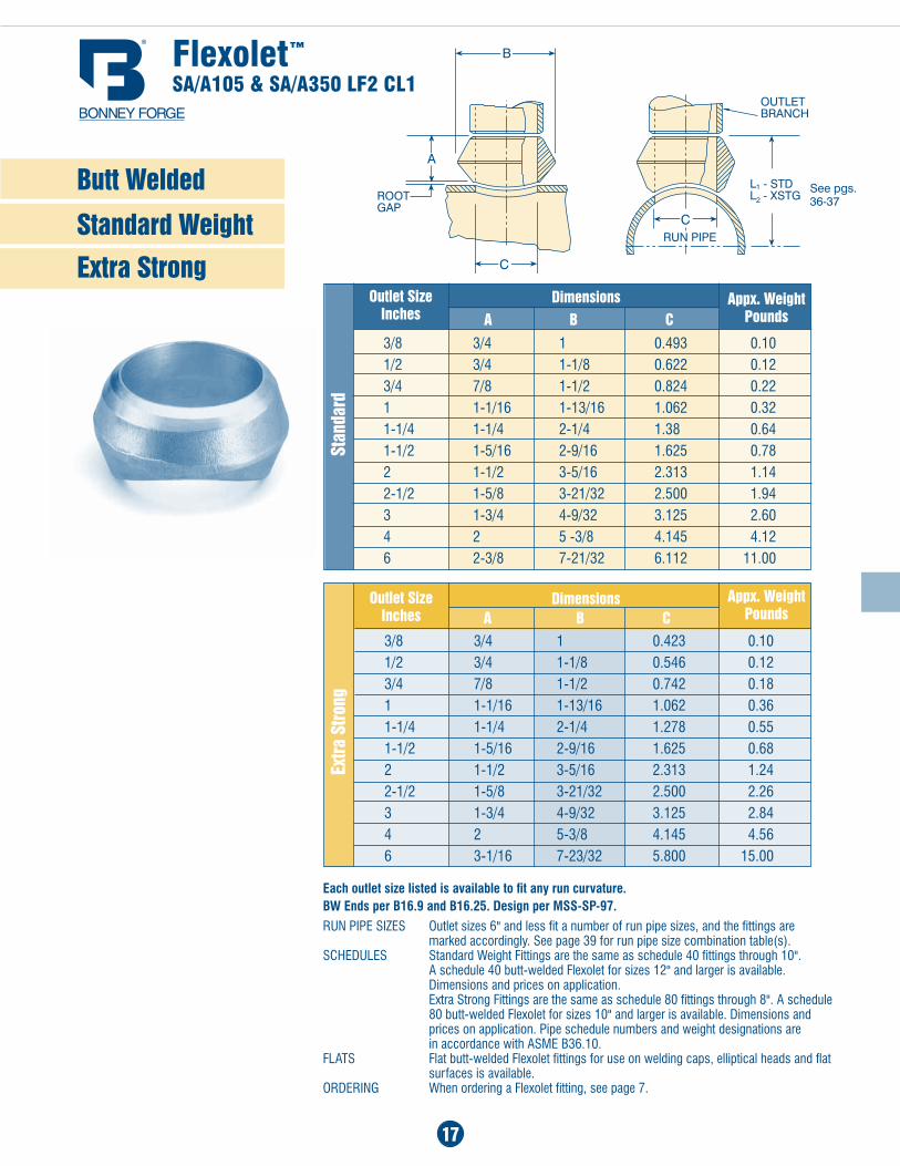
3/8 3/4 1 0.493 0.101/2 3/4 1-1/8 0.622 0.123/4 7/8 1-1/2 0.824 0.221 1-1/16 1-13/16 1.062 0.321-1/4 1-1/4 2-1/4 1.38 0.641-1/2 1-5/16 2-9/16 1.625 0.782 1-1/2 3-5/16 2.313 1.142-1/2 1-5/8 3-21/32 2.500 1.943 1-3/4 4-9/32 3.125 2.604 2 5 -3/8 4.145 4.126 2-3/8 7-21/32 6.112 11.00
Dimensions a B C
Outlet Size Inches
Stan
dard
Butt Welded
Standard Weight
Extra Strongappx. Weight
Pounds
Each outlet size listed is available to fit any run curvature. BW Ends per B16.9 and B16.25. Design per MSS-SP-97.
run PiPe SizeS Outlet sizes 6" and less fit a number of run pipe sizes, and the fittings are marked accordingly. See page 39 for run pipe size combination table(s). SCHEDULES Standard Weight Fittings are the same as schedule 40 fittings through 10". a schedule 40 butt-welded Flexolet for sizes 12" and larger is available. Dimensions and prices on application. Extra Strong Fittings are the same as schedule 80 fittings through 8". a schedule 80 butt-welded Flexolet for sizes 10" and larger is available. Dimensions and prices on application. Pipe schedule numbers and weight designations are in accordance with aSME B36.10.FLaTS Flat butt-welded Flexolet fittings for use on welding caps, elliptical heads and flat surfaces is available.ORDERING When ordering a Flexolet fitting, see page 7.
3/8 3/4 1 0.423 0.101/2 3/4 1-1/8 0.546 0.123/4 7/8 1-1/2 0.742 0.181 1-1/16 1-13/16 1.062 0.361-1/4 1-1/4 2-1/4 1.278 0.551-1/2 1-5/16 2-9/16 1.625 0.682 1-1/2 3-5/16 2.313 1.242-1/2 1-5/8 3-21/32 2.500 2.263 1-3/4 4-9/32 3.125 2.844 2 5-3/8 4.145 4.566 3-1/16 7-23/32 5.800 15.00
Dimensions a B C
Outlet Size Inches
Extra
Stro
ng
appx. Weight Pounds
Flexolet™
SA/A105 & SA/A350 LF2 CL1
See pgs. 36-37
18
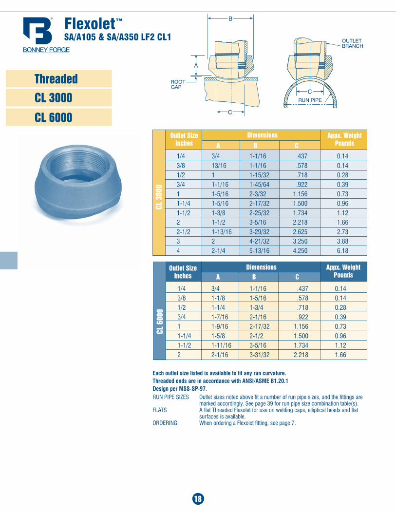
Threaded
CL 3000
CL 6000
1/4 3/4 1-1/16 .437 0.143/8 13/16 1-1/16 .578 0.141/2 1 1-15/32 .718 0.283/4 1-1/16 1-45/64 .922 0.391 1-5/16 2-3/32 1.156 0.731-1/4 1-5/16 2-17/32 1.500 0.961-1/2 1-3/8 2-25/32 1.734 1.122 1-1/2 3-5/16 2.218 1.662-1/2 1-13/16 3-29/32 2.625 2.733 2 4-21/32 3.250 3.884 2-1/4 5-13/16 4.250 6.18
Dimensions
a B COutlet Size
Inches
CL 3
000
1/4 3/4 1-1/16 .437 0.143/8 1-1/8 1-5/16 .578 0.141/2 1-1/4 1-3/4 .718 0.283/4 1-7/16 2-1/16 .922 0.391 1-9/16 2-17/32 1.156 0.731-1/4 1-5/8 2-1/2 1.500 0.961-1/2 1-11/16 3-5/16 1.734 1.122 2-1/16 3-31/32 2.218 1.66
Dimensions a B C
Outlet Size Inches
CL 6
000
appx. Weight Pounds
appx. Weight Pounds
Each outlet size listed is available to fit any run curvature. Threaded ends are in accordance with ANSI/ASME B1.20.1 Design per MSS-SP-97.run PiPe SizeS Outlet sizes noted above fit a number of run pipe sizes, and the fittings are marked accordingly. See page 39 for run pipe size combination table(s).FLaTS a flat Threaded Flexolet for use on welding caps, elliptical heads and flat surfaces is available.ORDERING When ordering a Flexolet fitting, see page 7.
Flexolet™
SA/A105 & SA/A350 LF2 CL1
19
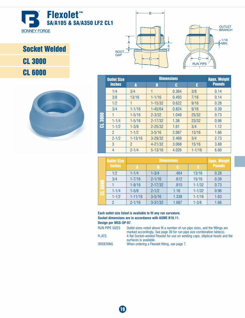
Socket Welded
CL 3000 CL 6000
1/4 3/4 1 0.364 3/8 0.143/8 13/16 1-1/16 0.493 7/16 0.141/2 1 1-15/32 0.622 9/16 0.283/4 1-1/16 1-45/64 0.824 9/16 0.391 1-5/16 2-3/32 1.049 25/32 0.731-1/4 1-5/16 2-17/32 1.38 23/32 0.961-1/2 1-3/8 2-25/32 1.61 3/4 1.122 1-1/2 3-5/16 2.067 13/16 1.662-1/2 1-13/16 3-29/32 2.469 3/4 2.733 2 4-21/32 3.068 15/16 3.884 2-1/4 5-13/16 4.026 1-1/16 6.60
Dimensions
a B C EOutlet Size
Inches
1/2 1-1/4 1-3/4 .464 13/16 0.283/4 1-7/16 2-1/16 .612 15/16 0.391 1-9/16 2-17/32 .815 1-1/32 0.731-1/4 1-5/8 2-1/2 1.16 1-1/32 0.961-1/2 1-11/16 3-5/16 1.338 1-1/16 1.632 2-1/16 3-31/32 1.687 1-3/8 1.66
DimensionsOutlet Size Inches
CL 3
000
CL 6
000
Flexolet™
SA/A105 & SA/A350 LF2 CL1
appx. Weight Pounds
appx. Weight Pounds
a B C E
Each outlet size listed is available to fit any run curvature. Socket dimensions are in accordance with ASME B16.11. Design per MSS-SP-97.run PiPe SizeS Outlet sizes noted above fit a number of run pipe sizes, and the fittings are marked accordingly. See page 39 for run pipe size combination table(s).FLaTS a flat Socket-welded Flexolet for use on welding caps, elliptical heads and flat surfaces is available.ORDERING When ordering a Flexolet fitting, see page 7.
20
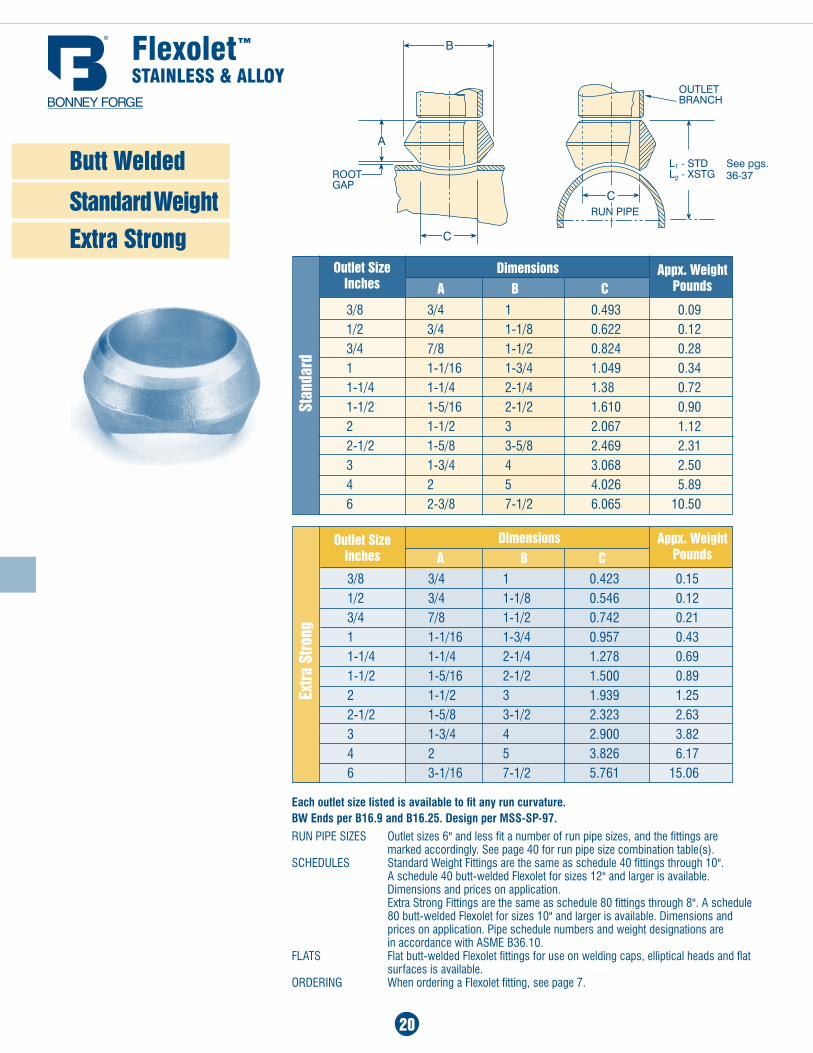
3/8 3/4 1 0.493 0.091/2 3/4 1-1/8 0.622 0.123/4 7/8 1-1/2 0.824 0.281 1-1/16 1-3/4 1.049 0.341-1/4 1-1/4 2-1/4 1.38 0.721-1/2 1-5/16 2-1/2 1.610 0.902 1-1/2 3 2.067 1.122-1/2 1-5/8 3-5/8 2.469 2.313 1-3/4 4 3.068 2.504 2 5 4.026 5.896 2-3/8 7-1/2 6.065 10.50
Dimensions a B C
Outlet Size Inches
Stan
dard
appx. Weight Pounds
Each outlet size listed is available to fit any run curvature. BW Ends per B16.9 and B16.25. Design per MSS-SP-97.
run PiPe SizeS Outlet sizes 6" and less fit a number of run pipe sizes, and the fittings are marked accordingly. See page 40 for run pipe size combination table(s). SCHEDULES Standard Weight Fittings are the same as schedule 40 fittings through 10". a schedule 40 butt-welded Flexolet for sizes 12" and larger is available. Dimensions and prices on application. Extra Strong Fittings are the same as schedule 80 fittings through 8". a schedule 80 butt-welded Flexolet for sizes 10" and larger is available. Dimensions and prices on application. Pipe schedule numbers and weight designations are in accordance with aSME B36.10.FLaTS Flat butt-welded Flexolet fittings for use on welding caps, elliptical heads and flat surfaces is available.ORDERING When ordering a Flexolet fitting, see page 7.
3/8 3/4 1 0.423 0.151/2 3/4 1-1/8 0.546 0.123/4 7/8 1-1/2 0.742 0.211 1-1/16 1-3/4 0.957 0.431-1/4 1-1/4 2-1/4 1.278 0.691-1/2 1-5/16 2-1/2 1.500 0.892 1-1/2 3 1.939 1.252-1/2 1-5/8 3-1/2 2.323 2.633 1-3/4 4 2.900 3.824 2 5 3.826 6.176 3-1/16 7-1/2 5.761 15.06
Dimensions a B C
Outlet Size Inches
Extra
Stro
ng
appx. Weight Pounds
Flexolet™
STAinLeSS & ALLOY
Butt Welded
Standard Weight Extra Strong
See pgs. 36-37
21
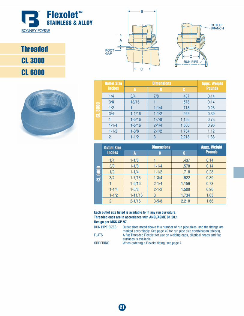
Threaded
CL 3000
CL 6000
1/4 3/4 7/8 .437 0.143/8 13/16 1 .578 0.141/2 1 1-1/4 .718 0.283/4 1-1/16 1-1/2 .922 0.391 1-5/16 1-7/8 1.156 0.731-1/4 1-5/16 2-1/4 1.500 0.961-1/2 1-3/8 2-1/2 1.734 1.122 1-1/2 3 2.218 1.66
Dimensions
a B COutlet Size
Inches
CL 3
000
1/4 1-1/8 1 .437 0.143/8 1-1/8 1-1/4 .578 0.141/2 1-1/4 1-1/2 .718 0.283/4 1-7/16 1-3/4 .922 0.391 1-9/16 2-1/4 1.156 0.731-1/4 1-5/8 2-1/2 1.500 0.961-1/2 1-11/16 3 1.734 1.632 2-1/16 3-5/8 2.218 1.66
Dimensions a B C
Outlet Size Inches
CL 6
000
appx. Weight Pounds
appx. Weight Pounds
Each outlet size listed is available to fit any run curvature. Threaded ends are in accordance with ANSI/ASME B1.20.1 Design per MSS-SP-97.run PiPe SizeS Outlet sizes noted above fit a number of run pipe sizes, and the fittings are marked accordingly. See page 40 for run pipe size combination table(s).FLaTS a flat Threaded Flexolet for use on welding caps, elliptical heads and flat surfaces is available.ORDERING When ordering a Flexolet fitting, see page 7.
Flexolet™
STAinLeSS & ALLOY
22
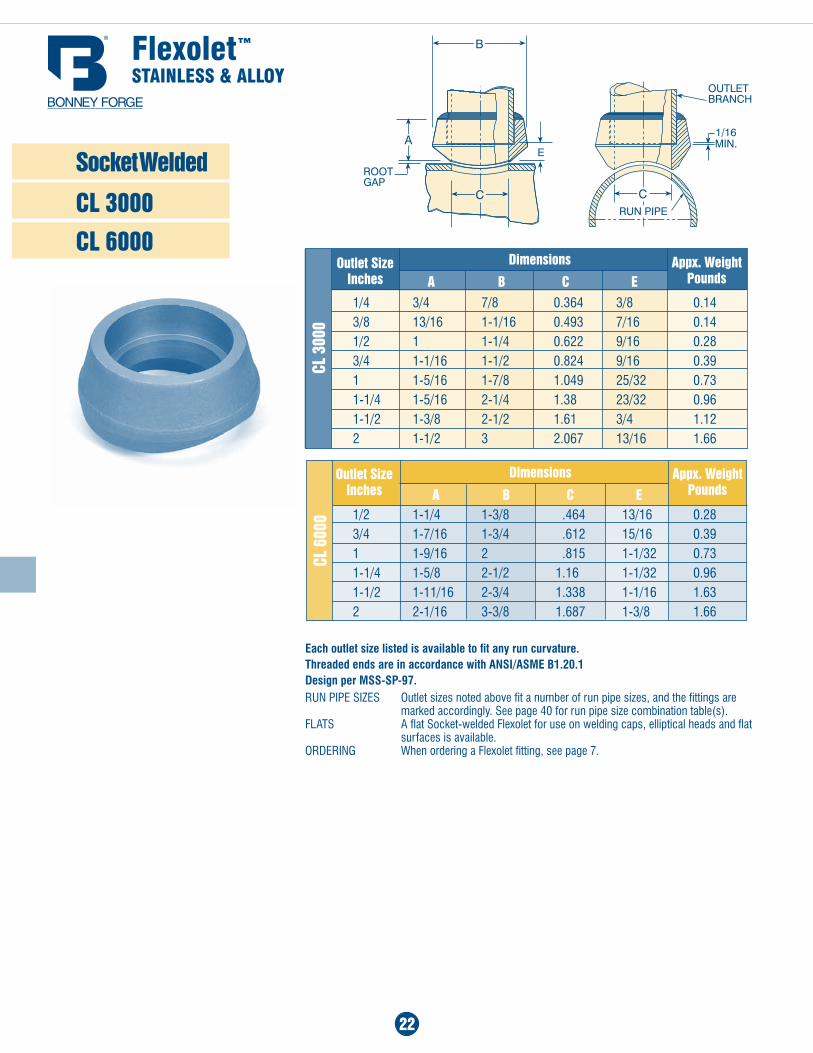
Socket Welded
CL 3000
CL 6000
1/4 3/4 7/8 0.364 3/8 0.143/8 13/16 1-1/16 0.493 7/16 0.141/2 1 1-1/4 0.622 9/16 0.283/4 1-1/16 1-1/2 0.824 9/16 0.391 1-5/16 1-7/8 1.049 25/32 0.731-1/4 1-5/16 2-1/4 1.38 23/32 0.961-1/2 1-3/8 2-1/2 1.61 3/4 1.122 1-1/2 3 2.067 13/16 1.66
Dimensions
a B C EOutlet Size
Inches
1/2 1-1/4 1-3/8 .464 13/16 0.283/4 1-7/16 1-3/4 .612 15/16 0.391 1-9/16 2 .815 1-1/32 0.731-1/4 1-5/8 2-1/2 1.16 1-1/32 0.961-1/2 1-11/16 2-3/4 1.338 1-1/16 1.632 2-1/16 3-3/8 1.687 1-3/8 1.66
DimensionsOutlet Size Inches
CL 3
000
CL 6
000
Flexolet™
STAinLeSS & ALLOY
appx. Weight Pounds
appx. Weight Pounds
a B C E
Each outlet size listed is available to fit any run curvature. Threaded ends are in accordance with ANSI/ASME B1.20.1 Design per MSS-SP-97.run PiPe SizeS Outlet sizes noted above fit a number of run pipe sizes, and the fittings are marked accordingly. See page 40 for run pipe size combination table(s).FLaTS a flat Socket-welded Flexolet for use on welding caps, elliptical heads and flat surfaces is available.ORDERING When ordering a Flexolet fitting, see page 7.
a B
23
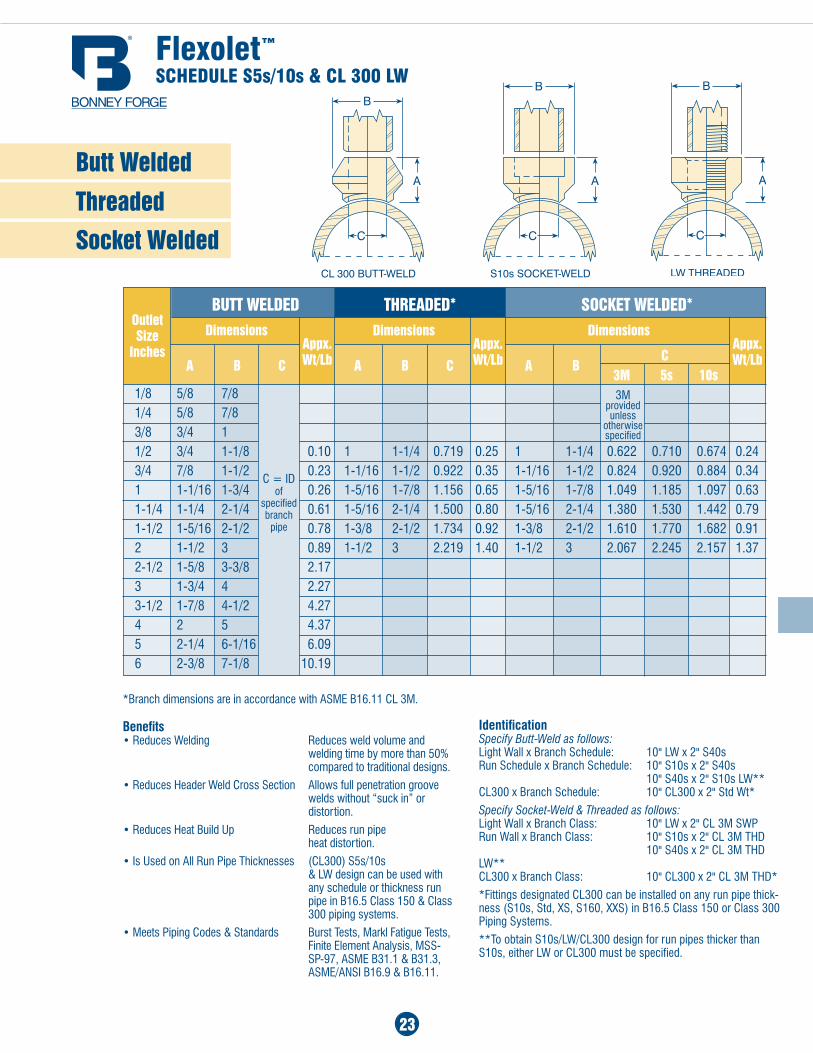
Butt Welded
Threaded
Socket Welded
DimensionsOutlet Size
Inches
Flexolet™
SCheduLe S5s/10s & CL 300 LW
appx. Wt/Lb a B C
*Branch dimensions are in accordance with aSME B16.11 CL 3M.
Benefits• Reduces Welding Reduces weld volume and
welding time by more than 50% compared to traditional designs.
• Reduces Header Weld Cross Section allows full penetration groove welds without “suck in” or distortion.
• Reduces Heat Build Up Reduces run pipe heat distortion.
• Is Used on all Run Pipe Thicknesses (CL300) S5s/10s & LW design can be used with any schedule or thickness run pipe in B16.5 Class 150 & Class 300 piping systems.
• Meets Piping Codes & Standards Burst Tests, Markl Fatigue Tests, Finite Element analysis, MSS- SP-97, aSME B31.1 & B31.3, aSME/aNSI B16.9 & B16.11.
Dimensionsappx. Wt/Lb a B C
Dimensionsappx. Wt/Lb C
3M 5s 10s
BUTT WELDED THREaDED* SOCkET WELDED*
IdentificationSpecify Butt-Weld as follows: Light Wall x Branch Schedule: 10" LW x 2" S40s Run Schedule x Branch Schedule: 10" S10s x 2" S40s 10" S40s x 2" S10s lW**CL300 x Branch Schedule: 10" CL300 x 2" Std Wt*
Specify Socket-Weld & Threaded as follows:Light Wall x Branch Class: 10" LW x 2" CL 3M SWPRun Wall x Branch Class: 10" S10s x 2" CL 3M THD 10" S40s x 2" Cl 3M thd lW**Cl300 x Branch Class: 10" Cl300 x 2" Cl 3M thd*
*Fittings designated CL300 can be installed on any run pipe thick-ness (S10s, Std, xS, S160, xxS) in B16.5 Class 150 or Class 300 Piping Systems.
**To obtain S10s/LW/CL300 design for run pipes thicker than S10s, either LW or CL300 must be specified.
1/8 5/8 7/8 1/4 5/8 7/8 3/8 3/4 1 1/2 3/4 1-1/8 0.10 1 1-1/4 0.719 0.25 1 1-1/4 0.622 0.710 0.674 0.24 3/4 7/8 1-1/2 0.23 1-1/16 1-1/2 0.922 0.35 1-1/16 1-1/2 0.824 0.920 0.884 0.34 1 1-1/16 1-3/4 0.26 1-5/16 1-7/8 1.156 0.65 1-5/16 1-7/8 1.049 1.185 1.097 0.63 1-1/4 1-1/4 2-1/4 0.61 1-5/16 2-1/4 1.500 0.80 1-5/16 2-1/4 1.380 1.530 1.442 0.79 1-1/2 1-5/16 2-1/2 0.78 1-3/8 2-1/2 1.734 0.92 1-3/8 2-1/2 1.610 1.770 1.682 0.91 2 1-1/2 3 0.89 1-1/2 3 2.219 1.40 1-1/2 3 2.067 2.245 2.157 1.37 2-1/2 1-5/8 3-3/8 2.17 3 1-3/4 4 2.27 3-1/2 1-7/8 4-1/2 4.27 4 2 5 4.37 5 2-1/4 6-1/16 6.09 6 2-3/8 7-1/8 10.19
3M provided unless
otherwise specified
C = id of
specified branch
pipe
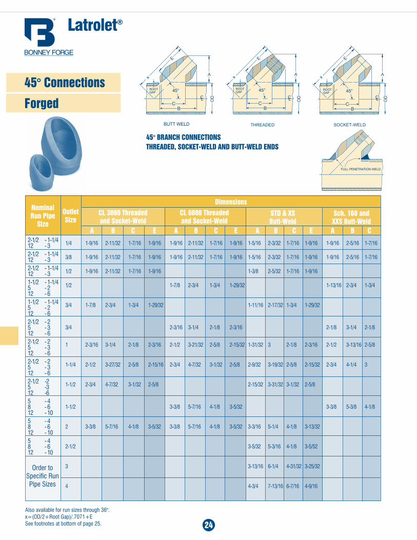
24
45° BRanCH COnnECTIOnS THREaDED, SOCkET-WELD anD BUTT-WELD EnDS
Latrolet®
Outlet Size
CL 3000 Threaded and Socket-Weld
CL 6000 Threaded and Socket-Weld
Dimensions
Order to Specific Run Pipe Sizes
45° Connections
Forged
also available for run sizes through 36". x=(OD/2+Root Gap)/.7071+E See footnotes at bottom of page 25.
2-1/2 - 1-1/4 12 - 32-1/2 - 1-1/4 12 - 32-1/2 - 1-1/4 12 - 31-1/2 - 1-1/4 5 - 2 12 - 61-1/2 - 1-1/4 5 - 2 12 - 62-1/2 - 2 5 - 3 12 - 62-1/2 - 2 5 - 3 12 - 62-1/2 - 2 5 - 3 12 - 62-1/2 -2 5 -3 12 -65 - 4 8 - 6 12 - 105 - 4 8 - 6 12 - 105 - 4 8 - 6 12 - 10
1/4 1-9/16 2-11/32 1-7/16 1-9/16 1-9/16 2-11/32 1-7/16 1-9/16 1-5/16 2-3/32 1-7/16 1-9/16 1-9/16 2-5/16 1-7/16
3/8 1-9/16 2-11/32 1-7/16 1-9/16 1-9/16 2-11/32 1-7/16 1-9/16 1-5/16 2-3/32 1-7/16 1-9/16 1-9/16 2-5/16 1-7/16
1/2 1-9/16 2-11/32 1-7/16 1-9/16 1-3/8 2-5/32 1-7/16 1-9/16
1/2 1-7/8 2-3/4 1-3/4 1-29/32 1-13/16 2-3/4 1-3/4
3/4 1-7/8 2-3/4 1-3/4 1-29/32 1-11/16 2-17/32 1-3/4 1-29/32
3/4 2-3/16 3-1/4 2-1/8 2-3/16 2-1/8 3-1/4 2-1/8 1 2-3/16 3-1/4 2-1/8 2-3/16 2-1/2 3-21/32 2-5/8 2-15/32 1-31/32 3 2-1/8 2-3/16 2-1/2 3-13/16 2-5/8
1-1/4 2-1/2 3-27/32 2-5/8 2-15/16 2-3/4 4-7/32 3-1/32 2-5/8 2-9/32 3-19/32 2-5/8 2-15/32 2-3/4 4-1/4 3
1-1/2 2-3/4 4-7/32 3-1/32 2-5/8 2-15/32 3-31/32 3-1/32 2-5/8
1-1/2 3-3/8 5-7/16 4-1/8 3-5/32 3-3/8 5-3/8 4-1/8
2 3-3/8 5-7/16 4-1/8 3-5/32 3-3/8 5-7/16 4-1/8 3-5/32 3-3/16 5-1/4 4-1/8 3-13/32
2-1/2 3-5/32 5-3/16 4-1/8 3-5/52
3 3-13/16 6-1/4 4-31/32 3-25/32
4 4-3/4 7-13/16 6-7/16 4-9/16
nominal Run Pipe
Size a B C E a B C E a B C E a B C
STD & XS Butt-Weld
Sch. 160 and XXS Butt-Weld
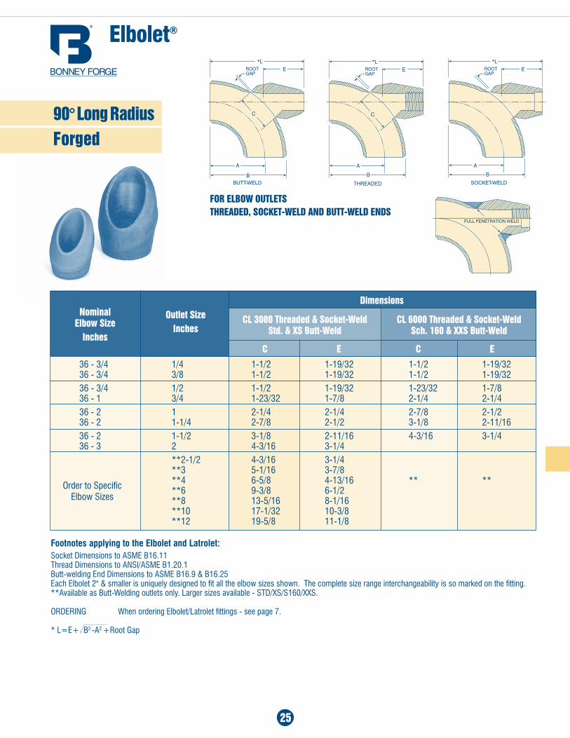
elbolet®
Footnotes applying to the Elbolet and Latrolet:Socket Dimensions to aSME B16.11Thread Dimensions to aNSI/aSME B1.20.1Butt-welding End Dimensions to aSME B16.9 & B16.25Each Elbolet 2" & smaller is uniquely designed to fit all the elbow sizes shown. The complete size range interchangeability is so marked on the fitting.**available as Butt-Welding outlets only. Larger sizes available - STD/xS/S160/xxS.
ORDERING When ordering Elbolet/Latrolet fittings - see page 7.
* l=e+ B2 -a2 +Root Gap
25
36 - 3/4 1/4 1-1/2 1-19/32 1-1/2 1-19/32 36 - 3/4 3/8 1-1/2 1-19/32 1-1/2 1-19/3236 - 3/4 1/2 1-1/2 1-19/32 1-23/32 1-7/8 36 - 1 3/4 1-23/32 1-7/8 2-1/4 2-1/436 - 2 1 2-1/4 2-1/4 2-7/8 2-1/2 36 - 2 1-1/4 2-7/8 2-1/2 3-1/8 2-11/1636 - 2 1-1/2 3-1/8 2-11/16 4-3/16 3-1/4 36 - 3 2 4-3/16 3-1/4 **2-1/2 4-3/16 3-1/4 **3 5-1/16 3-7/8 **4 6-5/8 4-13/16 ** ** **6 9-3/8 6-1/2 **8 13-5/16 8-1/16 **10 17-1/32 10-3/8 **12 19-5/8 11-1/8
CL 6000 Threaded & Socket-Weld Sch. 160 & XXS Butt-Weld
Order to Specific Elbow Sizes
Dimensionsnominal
Elbow Size Inches
Outlet SizeInches
CL 3000 Threaded & Socket-Weld Std. & XS Butt-Weld
C E C E
FOR ELBOW OUTLETS THREaDED, SOCkET-WELD anD BUTT-WELD EnDS
90° Long Radius Forged
26
BackgroundThe piping industry has retained the theory of “area replacement” for adequate and acceptable branch pipe reinforcement and very little basic improvement in branch pipe construction has taken place or indeed seemed possible. Area replacement has been the only premise outlined by Code for adequate reinforcement: the Codes have not considered the shape of such reinforcement. It is evident that some shapes would be more efficient than others, and as a result more replacement area with a poor shape might be less satisfactory than less area with an appropriate shape.The basic methods of lap type reinforcement outlined in Codes are known to have serious drawbacks, namely, that the geometry creates areas of high stress concentrations. They have an inherent crack at the inside edge of the fillet weld as well as points of high stress where the pad joins the run pipe and where the nozzle intersects the pad or run.These drawbacks are of increasing concern when high yield pipe is used and for other critical service applications such as nuclear. On softer materials such as Grade A or Grade B pipe the localized areas of high stress tend to be relieved by local yielding and generally do not adversely affect the serviceability of the joint unless cyclic loading is involved or there is a propensity for brittle fracture.
DesignThe Sweepolet® concept evolved from two premises, namely, reinforce-ment must be sufficient to limit deformations and that an efficient branch construction would result from controlling the geometry of the intersection on all planes.A Sweepolet fitting provides the required stiffening (reinforcement at the most critical point, the juncture of the branch and header) with essentially no peak stresses. Owing to the aesthetic proportions of a Sweepolet, designers intuitively know that it is an efficient branch outlet construction - and tests have proved it! As a result of experimental stress analysis from brittle lacquer to sophisticated and accurate three-dimensional pho-toelasticity, it has been shown that the Sweepolet embodies quantitatively all desirable features in their optimum relationship.
Code ComplianceThe Sweepolet is a contoured, integrally reinforced insert welding fitting developed by Bonney Forge. They have been approved for all critical-service applications including Class 1 Nuclear piping.The Codes have always anticipated the development of fittings such as our Sweepolet and approve their use. For example:aSME B31.3, PRoCESSINg PIPINg
Paragraphs 302.2, 304.3, 326 and 328.5.4 recognize and approve the use of special fittings.
aSME B31.1, PoWER PIPINg Paragraphs 102.2, 104.3, 126 and 127.4.8 similarly recognize and approve the use of special fittings.
aSME B31.4, Liquid Transportation Systems Paragraphs 402.2, 404.3, 406.5, 426 similarly recognize and approve the use of special fittings.
aSME B31.8, gas Transmission and distribution Piping Systems Paragraph 831.3 similarly recognize and approve the use of special fittings.
The Sweepolet complies with the requirements of ASME B16.9 “Fac-tory-Made Wrought Steel Buttwelding Fittings” and therefore satisfies various sections of the above noted ASME Codes for Pressure Piping. Additionally, an examination of the drawings in this catalog and/or the fittings themselves, show the vast improvement in this design over any other type of piping branch construction for resisting stresses in high yield pipe. Testing and in-service applications have already proven the serviceability of our Sweepolet product line and due to the substantial cost savings gained by using Sweepolets, anyone concerned with criti-cal piping systems should be interested in the use of this product.
Research & DevelopmentEver since Bonney Forge first began to question the basic premise of area replacement alone, intensive studies and research have been conducted by our engineers. It was soon found that the Pressure Vessel Industry was doing likewise. All signs of the Pressure Vessel Research Committee’s work on branch connections, both published and unpublished, point to the general shape of the Sweepolet. In fact, two of the nationally recognized pressure vessel and piping codes now contain requirements as to “area placement” in addition to the long-standing requirement on “area replacement.” In the meantime, the Sweepolet was independently conceived, developed, tested, sold and put into operation on pipelines, atomic reactor vessels, missile launching systems and numerous critical piping systems.In general, Bonney Forge's position is that shape influences the ef-ficiency of reinforcement as much or more than area provided by the indiscriminate application of area replacement rules. This theorem has appeared in Bonney Forge literature for years and has been the subject of many discussions with piping and pressure vessel designers during the last two decades. The question is: “What is the optimum shape and proper amount or reinforcement?” The answer is “Sweepolets! Experimental stress analyses, from brittle lacquer to sophisticated and accurate 3-dimensional photoelasticity have shown that the Sweepolet embodies quantitatively all desirable features in the optimum relationship.”
Sweepolet®
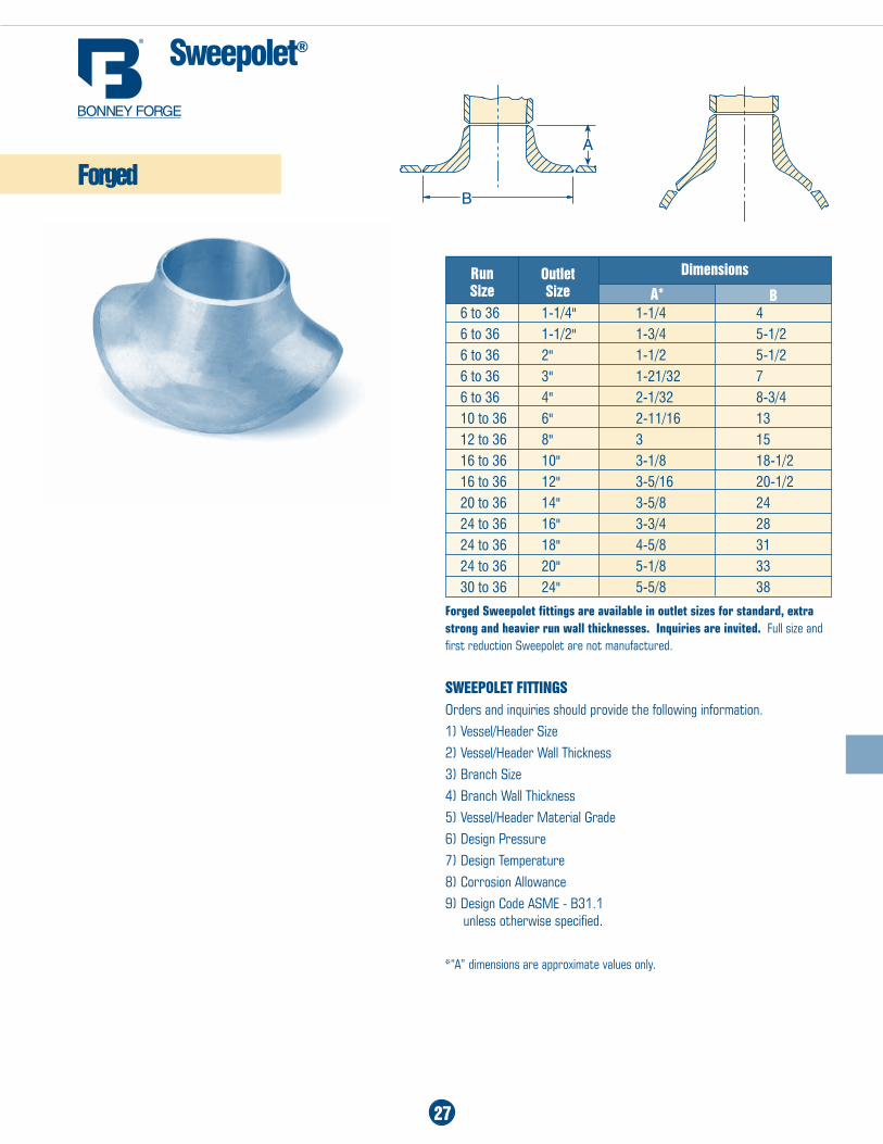
Sweepolet®
27
Run Size Ba*
Forged Sweepolet fittings are available in outlet sizes for standard, extra strong and heavier run wall thicknesses. Inquiries are invited. Full size and first reduction Sweepolet are not manufactured.
SWEEPOLET FITTIngSOrders and inquiries should provide the following information.1) Vessel/Header Size2) Vessel/Header Wall Thickness3) Branch Size4) Branch Wall Thickness5) Vessel/Header Material Grade6) Design Pressure7) Design Temperature8) Corrosion Allowance9) Design Code ASME - B31.1 unless otherwise specified.
*“A” dimensions are approximate values only.
6 to 36 1-1/4" 1-1/4 46 to 36 1-1/2" 1-3/4 5-1/26 to 36 2" 1-1/2 5-1/26 to 36 3" 1-21/32 76 to 36 4" 2-1/32 8-3/410 to 36 6" 2-11/16 1312 to 36 8" 3 1516 to 36 10" 3-1/8 18-1/216 to 36 12" 3-5/16 20-1/220 to 36 14" 3-5/8 2424 to 36 16" 3-3/4 2824 to 36 18" 4-5/8 3124 to 36 20" 5-1/8 3330 to 36 24" 5-5/8 38
Outlet Size
Forged
Dimensions
28
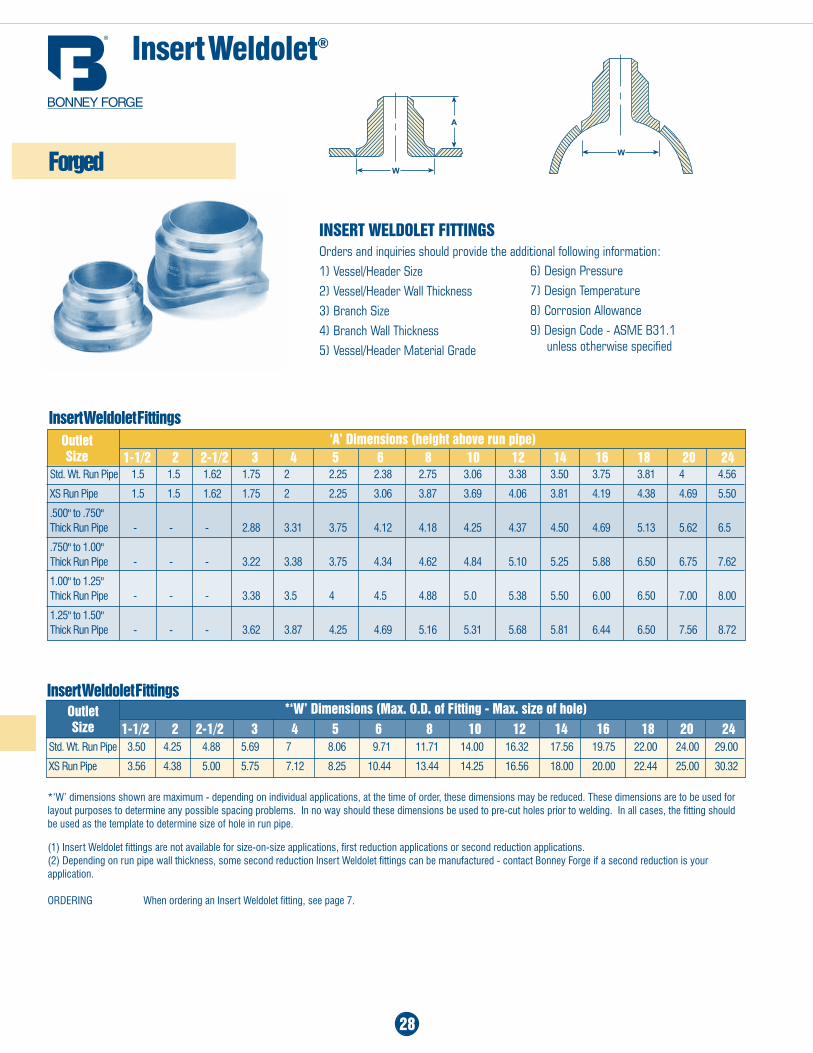
Std. Wt. Run Pipe 1.5 1.5 1.62 1.75 2 2.25 2.38 2.75 3.06 3.38 3.50 3.75 3.81 4 4.56
xS Run Pipe 1.5 1.5 1.62 1.75 2 2.25 3.06 3.87 3.69 4.06 3.81 4.19 4.38 4.69 5.50
.500" to .750" Thick Run Pipe - - - 2.88 3.31 3.75 4.12 4.18 4.25 4.37 4.50 4.69 5.13 5.62 6.5
.750" to 1.00" Thick Run Pipe - - - 3.22 3.38 3.75 4.34 4.62 4.84 5.10 5.25 5.88 6.50 6.75 7.62
1.00" to 1.25" Thick Run Pipe - - - 3.38 3.5 4 4.5 4.88 5.0 5.38 5.50 6.00 6.50 7.00 8.00
1.25" to 1.50" Thick Run Pipe - - - 3.62 3.87 4.25 4.69 5.16 5.31 5.68 5.81 6.44 6.50 7.56 8.72
‘a’ Dimensions (height above run pipe)
insert Weldolet®
Insert Weldolet Fittings
Insert Weldolet Fittings
(1) Insert Weldolet fittings are not available for size-on-size applications, first reduction applications or second reduction applications.(2) Depending on run pipe wall thickness, some second reduction Insert Weldolet fittings can be manufactured - contact Bonney Forge if a second reduction is your application.
ORDERING When ordering an Insert Weldolet fitting, see page 7.
1-1/2 2 2-1/2 3 4 5 6 8 10 12 14 16 18 20 24Outlet Size
*‘W’ dimensions shown are maximum - depending on individual applications, at the time of order, these dimensions may be reduced. These dimensions are to be used for layout purposes to determine any possible spacing problems. In no way should these dimensions be used to pre-cut holes prior to welding. In all cases, the fitting should be used as the template to determine size of hole in run pipe.
*‘W’ Dimensions (Max. O.D. of Fitting - Max. size of hole)1-1/2 2 2-1/2 3 4 5 6 8 10 12 14 16 18 20 24
Outlet Size
Std. Wt. Run Pipe 3.50 4.25 4.88 5.69 7 8.06 9.71 11.71 14.00 16.32 17.56 19.75 22.00 24.00 29.00
xS Run Pipe 3.56 4.38 5.00 5.75 7.12 8.25 10.44 13.44 14.25 16.56 18.00 20.00 22.44 25.00 30.32
InSERT WELDOLET FITTIngSOrders and inquiries should provide the additional following information:1) Vessel/Header Size2) Vessel/Header Wall Thickness3) Branch Size4) Branch Wall Thickness5) Vessel/Header Material Grade
Forged
6) Design Pressure7) Design Temperature8) Corrosion Allowance9) Design Code - ASME B31.1 unless otherwise specified
29
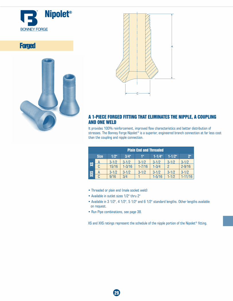
nipolet®
a 1-PIECE FORgED FITTIng THaT ELIMInaTES THE nIPPLE, a COUPLIng anD OnE WELDIt provides 100% reinforcement, improved flow characteristics and better distribution of stresses. The Bonney Forge Nipolet® is a superior, engineered branch connection at far less cost than the coupling and nipple connection.
• Threaded or plain end (male socket weld)• Available in outlet sizes 1/2" thru 2"• Available in 3 1/2", 4 1/2", 5 1/2" and 6 1/2" standard lengths. Other lengths available
on request.• Run Pipe combinations, see page 38.
XS and XXS ratings represent the schedule of the nipple portion of the Nipolet® fitting.
Plain End and Threaded
Size 1/2" 3/4" 1" 1-1/4" 1-1/2" 2"
a 3-1/2 3-1/2 3-1/2 3-1/2 3-1/2 3-1/2 C 15/16 1-3/16 1-7/16 1-3/4 2 2-9/16
a 3-1/2 3-1/2 3-1/2 3-1/2 3-1/2 3-1/2 C 9/16 3/4 1 1-5/16 1-1/2 1-11/16
Forged
XSXX
S
30
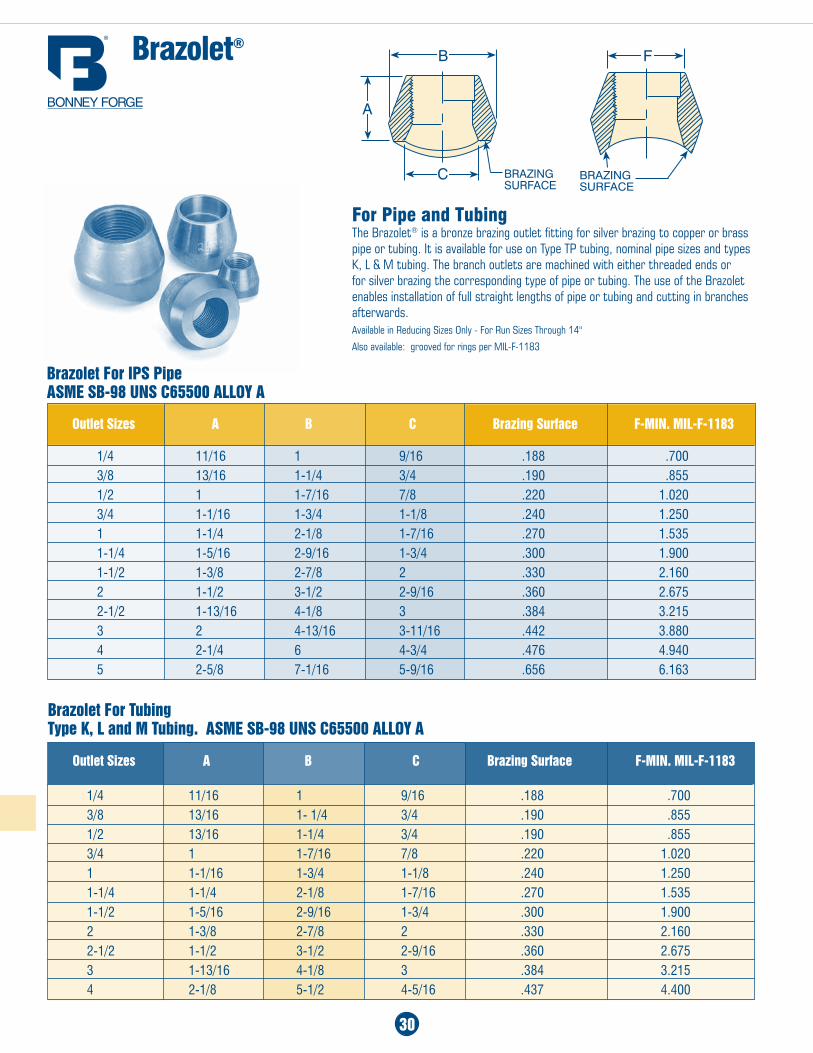
Brazolet®
For Pipe and TubingThe Brazolet® is a bronze brazing outlet fitting for silver brazing to copper or brass pipe or tubing. It is available for use on Type TP tubing, nominal pipe sizes and types K, L & M tubing. The branch outlets are machined with either threaded ends or for silver brazing the corresponding type of pipe or tubing. The use of the Brazolet enables installation of full straight lengths of pipe or tubing and cutting in branches afterwards.Available in Reducing Sizes Only - For Run Sizes Through 14"
Also available: grooved for rings per MIL-F-1183
Brazolet For IPS Pipe aSME SB-98 UnS C65500 aLLOY a
Outlet Sizes a B C Brazing Surface F-MIn. MIL-F-1183
1/4 11/16 1 9/16 .188 .7003/8 13/16 1-1/4 3/4 .190 .8551/2 1 1-7/16 7/8 .220 1.0203/4 1-1/16 1-3/4 1-1/8 .240 1.2501 1-1/4 2-1/8 1-7/16 .270 1.5351-1/4 1-5/16 2-9/16 1-3/4 .300 1.9001-1/2 1-3/8 2-7/8 2 .330 2.1602 1-1/2 3-1/2 2-9/16 .360 2.6752-1/2 1-13/16 4-1/8 3 .384 3.2153 2 4-13/16 3-11/16 .442 3.8804 2-1/4 6 4-3/4 .476 4.9405 2-5/8 7-1/16 5-9/16 .656 6.163
Outlet Sizes a B C Brazing Surface F-MIn. MIL-F-1183
1/4 11/16 1 9/16 .188 .7003/8 13/16 1- 1/4 3/4 .190 .8551/2 13/16 1-1/4 3/4 .190 .8553/4 1 1-7/16 7/8 .220 1.0201 1-1/16 1-3/4 1-1/8 .240 1.2501-1/4 1-1/4 2-1/8 1-7/16 .270 1.5351-1/2 1-5/16 2-9/16 1-3/4 .300 1.9002 1-3/8 2-7/8 2 .330 2.1602-1/2 1-1/2 3-1/2 2-9/16 .360 2.6753 1-13/16 4-1/8 3 .384 3.2154 2-1/8 5-1/2 4-5/16 .437 4.400
Brazolet For Tubing Type k, L and M Tubing. aSME SB-98 UnS C65500 aLLOY a
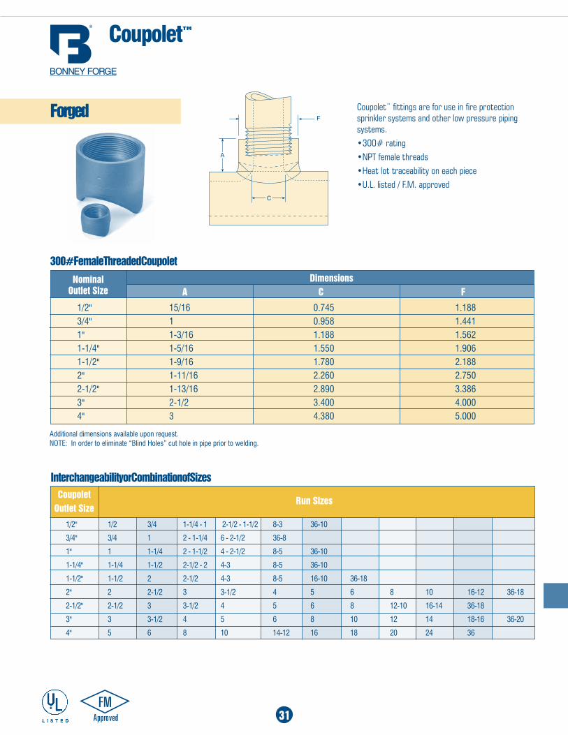
1/2" 15/16 0.745 1.1883/4" 1 0.958 1.4411" 1-3/16 1.188 1.5621-1/4" 1-5/16 1.550 1.9061-1/2" 1-9/16 1.780 2.1882" 1-11/16 2.260 2.7502-1/2" 1-13/16 2.890 3.3863" 2-1/2 3.400 4.0004" 3 4.380 5.000
additional dimensions available upon request.NOTE: In order to eliminate “Blind Holes” cut hole in pipe prior to welding.
300# Female Threaded Coupolet
1/2" 1/2 3/4 1-1/4 - 1 2-1/2 - 1-1/2 8-3 36-10
3/4" 3/4 1 2 - 1-1/4 6 - 2-1/2 36-8
1" 1 1-1/4 2 - 1-1/2 4 - 2-1/2 8-5 36-10
1-1/4" 1-1/4 1-1/2 2-1/2 - 2 4-3 8-5 36-10
1-1/2" 1-1/2 2 2-1/2 4-3 8-5 16-10 36-18
2" 2 2-1/2 3 3-1/2 4 5 6 8 10 16-12 36-18
2-1/2" 2-1/2 3 3-1/2 4 5 6 8 12-10 16-14 36-18
3" 3 3-1/2 4 5 6 8 10 12 14 18-16 36-20
4" 5 6 8 10 14-12 16 18 20 24 36
Interchangeability or Combination of Sizes
nominal Outlet Size
Dimensions
Coupolet Outlet Size
Run Sizes
Coupolet™
Coupolet™ fittings are for use in fire protection sprinkler systems and other low pressure piping systems.•300# rating•NPT female threads•Heat lot traceability on each piece•U.L. listed / F.M. approved
31
a C F
Forged
32
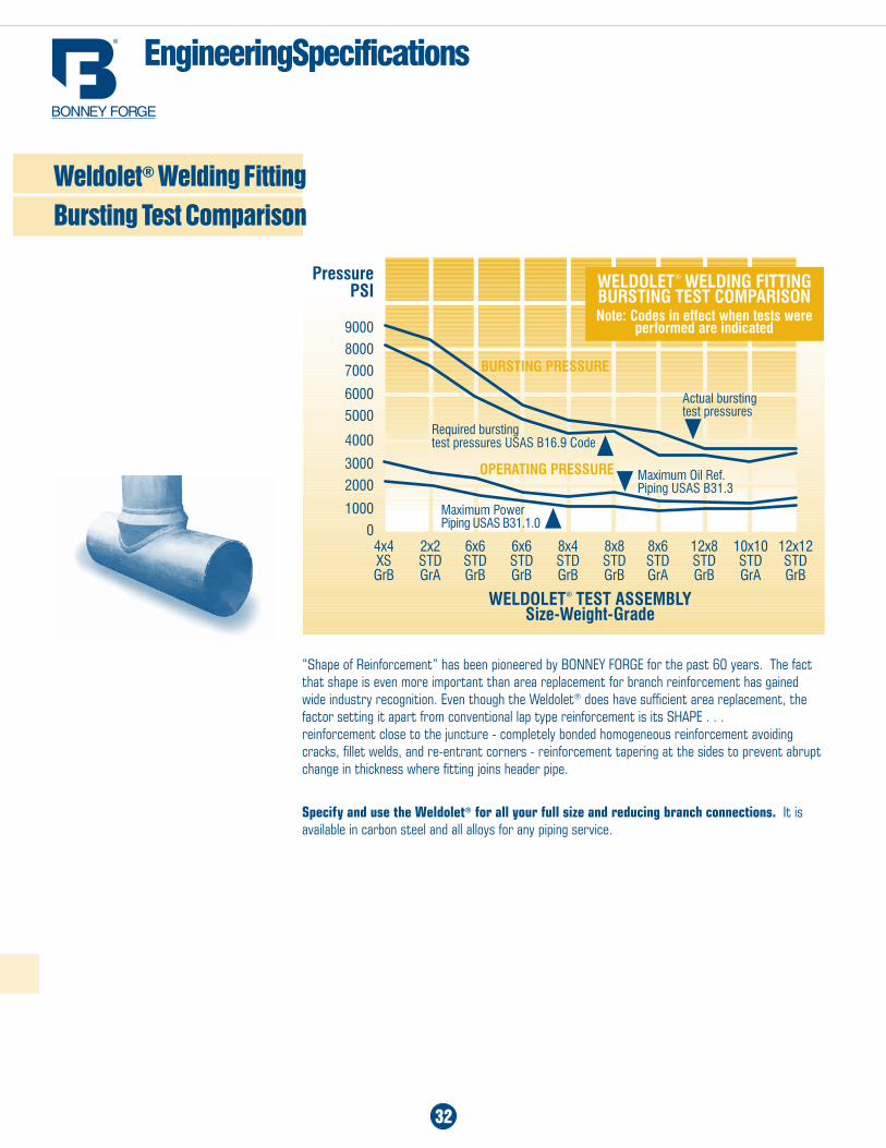
“Shape of Reinforcement” has been pioneered by BONNEY FORGE for the past 60 years. The fact that shape is even more important than area replacement for branch reinforcement has gained wide industry recognition. Even though the Weldolet® does have sufficient area replacement, the factor setting it apart from conventional lap type reinforcement is its SHAPE . . . reinforcement close to the juncture - completely bonded homogeneous reinforcement avoiding cracks, fillet welds, and re-entrant corners - reinforcement tapering at the sides to prevent abrupt change in thickness where fitting joins header pipe.
Specify and use the Weldolet® for all your full size and reducing branch connections. It is available in carbon steel and all alloys for any piping service.
engineering Specifications
Weldolet® Welding Fitting Bursting Test Comparison
Use Integrally Reinforced Weldolet® Welding Fittings Which Eliminate Computation. After determining that a branch needs reinforcement because of internal pressure of external forces or because of the high hazard of pipe failure, the designer can avoid further calculating by the specification of Weldolet welding fittings, specifically designed to compensate for the primary and secondary stress factors. The Weldolet fully integrates the branch and run pipe with the heaviest reinforcement at the crotch. The Weldolet blends the branch into the run pipe without abrupt transitions or sharp re-entrant corners present when the reinforcement is not completely integrated with the branch and run, such as with pad reinforced nozzles. The funneled inlet of the Weldolet provides a wide, stable footing which relieves stress concentrations and improves fluid flow.
EVEN WHERE CaLCULaTIoNS SHoW THaT REINFoRCEMENT IS NoT REQUIREd, the designer should, and in some cases must, satisfy himself on the following features and determine whether the use of the Weldolet is “good engineering” compared with the use of mitered branch nozzle construction.
1. FLUId FLoW - The internal funnel of the Weldolet fitting avoids the impeded flow caused by the abrupt 90° angle of a mitered nozzle.
2. LaRgE BRaNCHES oN LaRgE MaINS - An unreinforced branch connection (nozzle), even when competently installed, is considerably weaker than the pipe. The amount of reinforcement necessary to restore the joint to full pipe strength requires complex calculations as outlined in the Code. The use of the Weldolet avoids these calculations and provides 100% pipe strength branch connections as required by Code.
3. SMaLL BRaNCHES oN LaRgE MaINS - All branches 2" and smaller should be constructed with a Weldolet, Thredolet or Sockolet, whether reinforcement is required or not. Bonney Forge fittings provide the least expensive method of constructing branch connections in these sizes. Operating experience with piping systems points out the need for improved methods of attaching small pipes to large mains. The Weldolet fitting provides the ideal method of making the transition.
4. WoRKMaNSHIP - Fabrication with a Weldolet avoids the abuses encountered in the field with mitered branch connections as outlined on page 5.
33
engineering Specifications
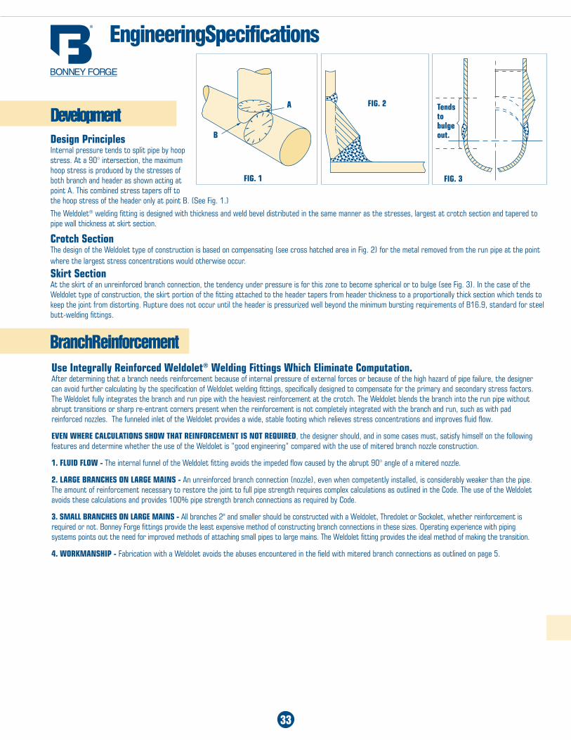
Developmentdesign Principles Internal pressure tends to split pipe by hoop stress. At a 90° intersection, the maximum hoop stress is produced by the stresses of both branch and header as shown acting at point A. This combined stress tapers off to the hoop stress of the header only at point B. (See Fig. 1.)
The Weldolet® welding fitting is designed with thickness and weld bevel distributed in the same manner as the stresses, largest at crotch section and tapered to pipe wall thickness at skirt section.
Crotch Section The design of the Weldolet type of construction is based on compensating (see cross hatched area in Fig. 2) for the metal removed from the run pipe at the point where the largest stress concentrations would otherwise occur. Skirt Section At the skirt of an unreinforced branch connection, the tendency under pressure is for this zone to become spherical or to bulge (see Fig. 3). In the case of the Weldolet type of construction, the skirt portion of the fitting attached to the header tapers from header thickness to a proportionally thick section which tends to keep the joint from distorting. Rupture does not occur until the header is pressurized well beyond the minimum bursting requirements of B16.9, standard for steel butt-welding fittings.
Branch Reinforcement
FIg. 1
FIg. 2
FIg. 3
a
B
Tends to bulge out.
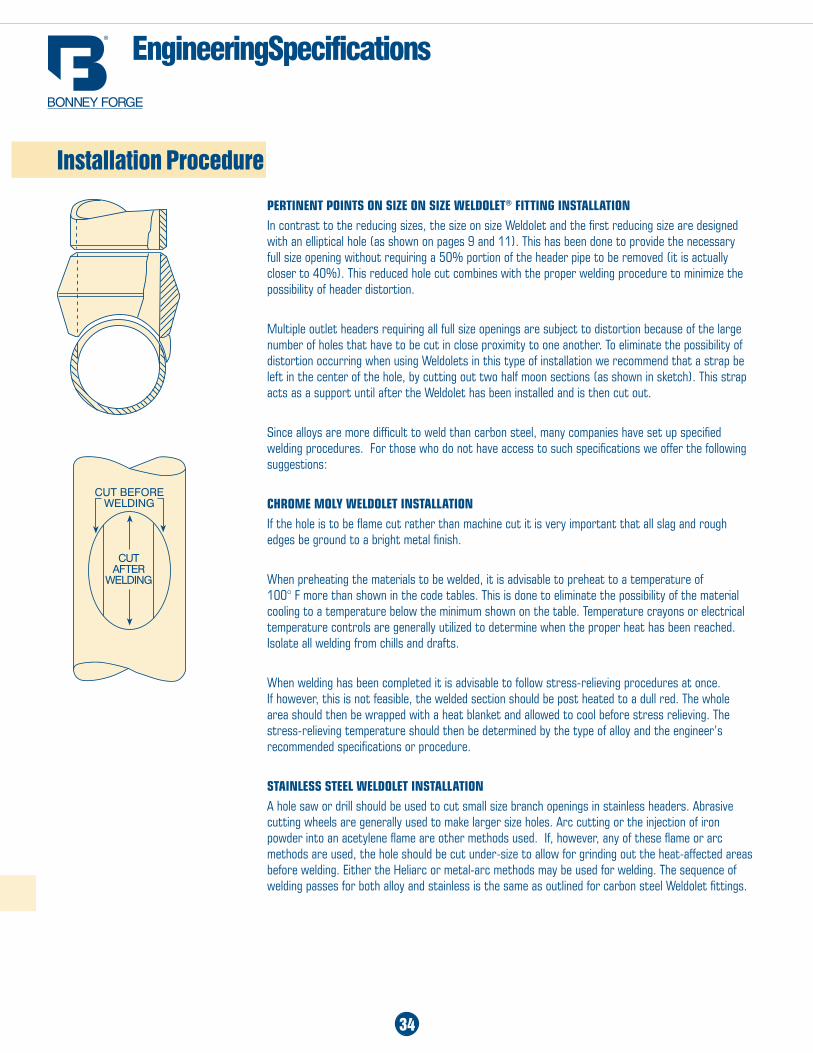
PERTINENT PoINTS oN SIZE oN SIZE WELdoLET® FITTINg INSTaLLaTIoNIn contrast to the reducing sizes, the size on size Weldolet and the first reducing size are designed with an elliptical hole (as shown on pages 9 and 11). This has been done to provide the necessary full size opening without requiring a 50% portion of the header pipe to be removed (it is actually closer to 40%). This reduced hole cut combines with the proper welding procedure to minimize the possibility of header distortion.
Multiple outlet headers requiring all full size openings are subject to distortion because of the large number of holes that have to be cut in close proximity to one another. To eliminate the possibility of distortion occurring when using Weldolets in this type of installation we recommend that a strap be left in the center of the hole, by cutting out two half moon sections (as shown in sketch). This strap acts as a support until after the Weldolet has been installed and is then cut out.
Since alloys are more difficult to weld than carbon steel, many companies have set up specified welding procedures. For those who do not have access to such specifications we offer the following suggestions:
CHRoME MoLY WELdoLET INSTaLLaTIoNIf the hole is to be flame cut rather than machine cut it is very important that all slag and rough edges be ground to a bright metal finish.
When preheating the materials to be welded, it is advisable to preheat to a temperature of 100° F more than shown in the code tables. This is done to eliminate the possibility of the material cooling to a temperature below the minimum shown on the table. Temperature crayons or electrical temperature controls are generally utilized to determine when the proper heat has been reached. Isolate all welding from chills and drafts.
When welding has been completed it is advisable to follow stress-relieving procedures at once. If however, this is not feasible, the welded section should be post heated to a dull red. The whole area should then be wrapped with a heat blanket and allowed to cool before stress relieving. The stress-relieving temperature should then be determined by the type of alloy and the engineer’s recommended specifications or procedure.
STaINLESS STEEL WELdoLET INSTaLLaTIoNA hole saw or drill should be used to cut small size branch openings in stainless headers. Abrasive cutting wheels are generally used to make larger size holes. Arc cutting or the injection of iron powder into an acetylene flame are other methods used. If, however, any of these flame or arc methods are used, the hole should be cut under-size to allow for grinding out the heat-affected areas before welding. Either the Heliarc or metal-arc methods may be used for welding. The sequence of welding passes for both alloy and stainless is the same as outlined for carbon steel Weldolet fittings.
engineering Specifications
Installation Procedure
34
engineering Specifications
Installation Procedure
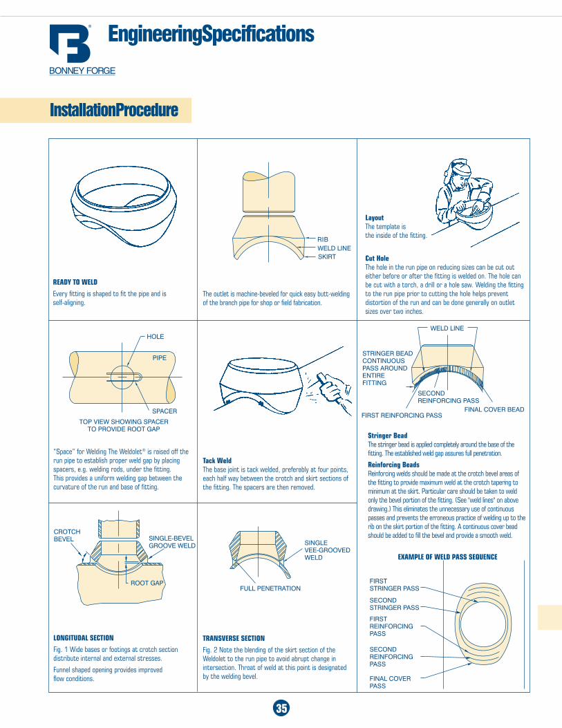
REadY To WELd
Every fitting is shaped to fit the pipe and is self-aligning.
“Space” for Welding The Weldolet® is raised off the run pipe to establish proper weld gap by placing spacers, e.g. welding rods, under the fitting. This provides a uniform welding gap between the curvature of the run and base of fitting.
LoNgITUdaL SECTIoN
Fig. 1 Wide bases or footings at crotch section distribute internal and external stresses.
Funnel shaped opening provides improved flow conditions.
The outlet is machine-beveled for quick easy butt-welding of the branch pipe for shop or field fabrication.
Tack Weld The base joint is tack welded, preferably at four points, each half way between the crotch and skirt sections of the fitting. The spacers are then removed.
TRaNSVERSE SECTIoN
Fig. 2 Note the blending of the skirt section of the Weldolet to the run pipe to avoid abrupt change in intersection. Throat of weld at this point is designated by the welding bevel.
Layout The template is the inside of the fitting.
Cut Hole The hole in the run pipe on reducing sizes can be cut out either before or after the fitting is welded on. The hole can be cut with a torch, a drill or a hole saw. Welding the fitting to the run pipe prior to cutting the hole helps prevent distortion of the run and can be done generally on outlet sizes over two inches.
RIBWELD LINESkIRt
hoLE
PIPE
SPacER
toP VIEW ShoWING SPacER to PRoVIDE Root GaP
WELD LINE
FIRSt REINFoRcING PaSS
SEcoND REINFoRcING PaSS
FINaL coVER BEaD
StRINGER BEaD coNtINuouS PaSS aRouND ENtIRE FIttING
FIRSt StRINGER PaSS
SEcoND StRINGER PaSS
FIRSt REINFoRcING PaSS
SEcoND REINFoRcING PaSS
FINaL coVER PaSS
ExaMPLE oF WELd PaSS SEQUENCE
SINGLE VEE-GRooVED WELD
FuLL PENEtRatIoN
cRotch BEVEL SINGLE-BEVEL
GRooVE WELD
Root GaP
Stringer Bead The stringer bead is applied completely around the base of the fitting. The established weld gap assures full penetration.
Reinforcing Beads Reinforcing welds should be made at the crotch bevel areas of the fitting to provide maximum weld at the crotch tapering to minimum at the skirt. Particular care should be taken to weld only the bevel portion of the fitting. (See "weld lines" on above drawing.) This eliminates the unnecessary use of continuous passes and prevents the erroneous practice of welding up to the rib on the skirt portion of the fitting. A continuous cover bead should be added to fill the bevel and provide a smooth weld.
35
1/8 1/4 3/8 1/2 3/4 1 1-1/4 1-1/2 2 2-1/2 3
3/8 STD L1 1 1 XS L2 1 1
1/2 STD L1 1-1/16 1-1/16 1-3/16 1-3/16 XS L2 1-1/16 1-1/16 1-3/16 1-3/16 S160 & XXS L3 1-1/2
3/4 STD L1 1-3/16 1-3/16 1-1/4 1-1/4 1-7/16 XS L2 1-3/16 1-3/16 1-1/4 1-1/4 1-7/16 S160 & XXS L3 1-5/8 1-3/4
1 STD L1 1-5/16 1-5/16 1-3/8 1-3/8 1-1/2 1-11/16 XS L2 1-5/16 1-5/16 1-3/8 1-3/8 1-1/2 1-11/16 S160 & XXS L3 1-3/4 1-7/8 2-1/8
1-1/4 STD L1 1-7/16 1-7/16 1-9/16 1-9/16 1-11/16 1-7/8 2-1/16 XS L2 1-7/16 1-7/16 1-9/16 1-9/16 1-11/16 1-7/8 2-1/16 S160 & XXS L3 1-15/16 2-1/16 2-5/16 2-9/16
1-1/2 STD L1 1-9/16 1-9/16 1-11/16 1-11/16 1-13/16 2 2-3/16 2-1/4 XS L2 1-9/16 1-9/16 1-11/16 1-11/16 1-13/16 2 2-3/16 2-1/4 S160 & XXS L3 2-1/16 2-3/16 2-7/16 2-11/16 2-15/16
2 STD L1 1-13/16 1-13/16 1-15/16 1-15/16 2-1/16 2 1/4 2-7/16 2-1/2 2-11/16 XS L2 1-13/16 1-13/16 1-15/16 1-15/16 2-1/16 2-1/4 2-7/16 2-1/2 2-11/16 S160 & XXS L3 2-5/16 2-7/16 2-11/16 2-15/16 3-3/16 3-3/8
2-1/2 STD L1 2-1/16 2-1/16 2-3/16 2-3/16 2-5/16 2-1/2 2-11/16 2-3/4 2-15/16 3-1/16 XS L2 2-1/16 2-1/16 2-3/16 2-3/16 2-5/16 2-1/2 2-11/16 2-3/4 2-15/16 3-1/16 S160 & xxs L3 2-9/16 2-11/16 2-15/16 3-3/16 3-7/16 3-5/8 3-7/8
3 STD L1 2-3/8 2-3/8 2-1/2 2-1/2 2-5/8 2-13/16 3 3-1/16 3-1/4 3-3/8 3-1/2 XS L2 2-3/8 2-3/8 2-1/2 2-1/2 2-5/8 2-13/16 3 3-1/16 3-1/4 3-3/8 3-1/2 S160 & XXS L3 2-7/8 2-7/8 3 3-1/4 3-1/2 3-3/4 3-15/16 4-3/16 4-5/8
3-1/2 STD L1 2-5/8 2-5/8 2-3/4 2-3/4 2-7/8 3-1/16 3-1/4 3-5/16 3-1/2 3-5/8 3-3/4 XS L2 2 5/8 2 5/8 2-3/4 2-3/4 2-7/8 3-1/16 3-1/4 3-5/16 3-1/2 3-5/8 3-3/4
4 STD L1 2-7/8 2-7/8 3 3 3-1/8 3-5/16 3-1/2 3-9/16 3-3/4 3-7/8 4 XS L2 2 7/8 2-7/8 3 3 3-1/8 3-5/16 3-1/2 3-9/16 3-3/4 3-7/8 4 S160 & XXS L3 3-3/8 3-1/2 3-3/4 4 4-1/4 4-7/16 4-11/16 5-1/8
5 STD L1 3-7/16 3-7/16 3-9/16 3-9/16 3-11/16 3-7/8 4-1/16 4-1/8 4-5/16 4-7/16 4-9/16 XS L2 3-7/16 3-7/16 3-9/16 3-9/16 3-11/16 3-7/8 4-1/16 4-1/8 4-5/16 4-7/16 4-9/16 S160 & XXS L3 3-15/16 4-1/16 4-5/16 4-9/16 4-13/16 5 5-1/4 5 -11/16
6 STD L1 3-15/16 3-15/16 4-1/16 4-1/16 4-3/16 4-3/8 4-9/16 4-5/8 4-13/16 4-15/16 5-1/16 XS L2 3-15/16 3-15/16 4-1/16 4-1/16 4-3/16 4-3/8 4-9/16 4-5/8 4-13/16 4-15/16 5-1/16 S160 & XXS L3 4-7/16 4-9/16 4-13/16 5-11/6 5-5/16 5-1/2 5-3/4 6-3/16
8 STD L1 4-15/16 4-15/16 5-1/16 5-1/16 5-3/16 5-3/8 5-9/16 5-5/8 5-13/16 5-15/16 6-1/16 XS L2 4-15/16 4-15/16 5-1/16 5-1/16 5-3/16 5-3/8 5-9/16 5-5/8 5-13/16 5-15/16 6-1/16
10 STD L1 6 6 6-1/8 6-1/8 6-1/4 6-7/16 6-5/8 6-11/16 6-7/8 7 7-1/8 XS L2 6 6 6-1/8 6-1/8 6-1/4 6-7/16 6-5/8 6-11/16 6-7/8 7 7-1/8
12 STD L1 7 7 7-1/8 7-1/8 7-1/4 7-7/16 7-5/8 7-11/16 7-7/8 8 8-1/8 XS L2 7 7 7-1/8 7-1/8 7-1/4 7-7/16 7-5/8 7-11/16 7-7/8 8 8-1/8
14 STD L1 7-5/8 7-5/8 7-3/4 7-3/4 7-7/8 8-1/16 8-1/4 8-5/16 8-1/2 8-5/8 8-3/4 XS L2 7-5/8 7-5/8 7-3/4 7-3/4 7-7/8 8-1/16 8-1/4 8-5/16 8-1/2 8-5/8 8-3/4
16 STD L1 8-5/8 8-5/8 8-3/4 8-3/4 8-7/8 9-1/16 9-1/4 9-5/16 9-1/2 9-5/8 9-3/4 XS L2 8-5/8 8-5/8 8-3/4 8-3/4 8-7/8 9-1/16 9-1/4 9-5/16 9-1/2 9-5/8 9-3/4
18 STD L1 9-5/8 9-5/8 9-3/4 9-3/4 9-7/8 10-1/16 10-1/4 10-5/16 10-1/2 10-5/8 10-3/4 XS L2 9-5/8 9-5/8 9-3/4 9-3/4 9-7/8 10-1/16 10-1/4 10-5/16 10-1/2 10-5/8 10-3/4
20 STD L1 10-5/8 10-5/8 10-3/4 10-3/4 10-7/8 11-1/16 11-1/4 11-5/16 11-1/2 11-5/8 11-3/4 XS L2 10 -5/8 10-5/8 10-3/4 10-3/4 10-7/8 11-1/16 11-1/4 11-5/16 11-1/2 11-5/8 11-3/4
24 STD L1 12-5/8 12-5/8 12-3/4 12-3/4 12-7/8 13-1/16 13-1/4 13-5/16 13-1/2 13-5/8 13-3/4 XS L2 12-5/8 12-5/8 12-3/4 12-3/4 12-7/8 13-1/16 13-1/4 13-5/16 13-1/2 13-5/8 13-3/4
36
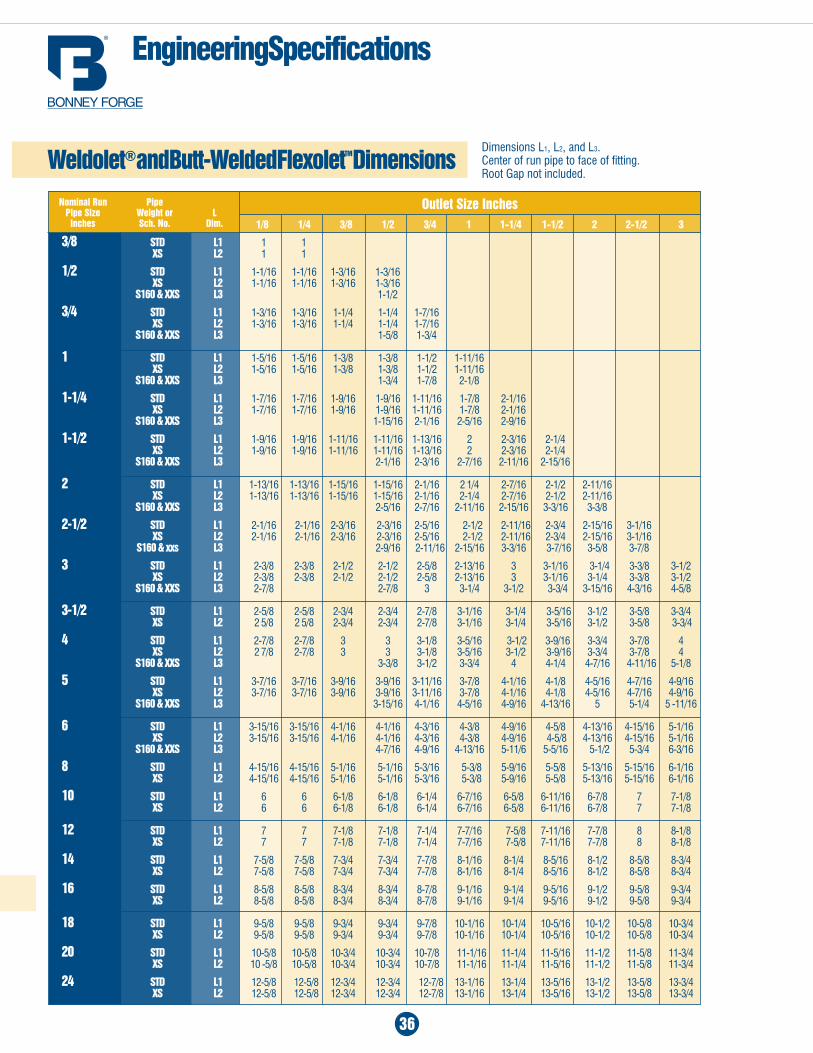
engineering Specifications
Weldolet® and Butt-Welded FlexoletTM Dimensions
Outlet Size Inches
dimensions l1, l2, and L3. Center of run pipe to face of fitting.Root Gap not included.
nominal Run Pipe Pipe Size Weight or L Inches Sch. no. Dim.
37
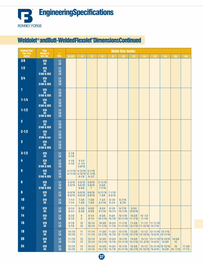
engineering Specifications
Weldolet® and Butt-Welded FlexoletTM Dimensions Continued
Outlet Size Inches nominal Run Pipe Pipe Size Weight or L Inches Sch. no. Dim. 3-1/2 4 5 6 8 10 12 14 16 18 20 24
3/8 STD L1 XS L2
1/2 STD L1 XS L2 S160 & XXS L3
3/4 STD L1 XS L2 S160 & XXS L3
1 STD L1 XS L2 S160 & XXS L3
1-1/4 STD L1 XS L2 S160 & XXS L3
1-1/2 STD L1 XS L2 S160 & XXS L3
2 STD L1 XS L2 S160 & XXS L3
2-1/2 STD L1 XS L2 S160 & xxs L3
3 STD L1 XS L2 S160 & XXS L3
3-1/2 STD L1 3-7/8 XS L2 3-7/8
4 STD L1 4-1/8 4-1/4 XS L2 4-1/8 4 -1/4 S160 & XXS L3 5-9/16
5 STD L1 4-11/16 4-13/16 5-1/16 XS L2 4-11/16 4-13/16 5 -1/16 S160 & XXS L3 6-1/8 6-1/2
6 STD L1 5-3/16 5-5/16 5-9/16 5-11/16 XS L2 5-3/16 5-5/16 5-9/16 6-3/8 S160 & XXS L3 6-5/8 7 7-7/16
8 STD L1 6-3/16 6-5/16 6-9/16 6-11/16 7-1/16 XS L2 6-3/16 6-5/16 6-9/16 7-3/8 8-3/16
10 STD L1 7-1/4 7-3/8 7-5/8 7-3/4 8-1/8 8-7/16 XS L2 7-1/4 7-3/8 7-5/8 8-7/16 9-1/4 8-7/8
12 STD L1 8-1/4 8-3/8 8-5/8 8-3/4 9-1/8 9-7/16 9-3/4 XS L2 8-1/4 8-3/8 8-5/8 9-7/16 10-1/4 10-1/16 10-5/16
14 STD L1 8-7/8 9 9-1/4 9-3/8 9-3/4 10-1/16 10-3/8 10 -1/2 XS L2 8-7/8 9 9-1/4 10-1/16 10-7/8 10-11/16 11-1/16 11-1/8
16 STD L1 9-7/8 10 10-1/4 10-3/8 10-3/4 11-1/16 11-3/8 11-1/2 11-11/16 XS L2 9-7/8 10 10-1/4 11-1/16 11-7/8 11-11/16 12-1/16 11-15/16 12-7/16
18 STD L1 10-7/8 11 11-1/4 11-3/8 11-3/4 12-1/16 12-3/8 12-1/2 12-11/16 13-1/16 XS L2 10-7/8 11 11-1/4 12-1/16 12-7/8 12 -11/16 13-1/16 12-15/16 13-3/16 13-11/16
20 STD L1 11-7/8 12 12-1/4 12-3/8 12-3/4 13-1/16 13-3/8 13-1/2 13-11/16 13-13/16 14-5/8 XS L2 11-7/8 12 12-1/4 13-1/16 13-7/8 13-11/16 14-1/16 13 -5/16 14-3/16 14-3/8 15
24 STD L1 13-7/8 14 14-1/4 14-3/8 14-3/4 15-1/16 15-3/8 15-1/2 15-11/16 15-13/16 16 17-3/8 XS L2 13-7/8 14 14-1/4 15-1/16 15-7/8 15-11/16 16-1/16 15-15/16 16-3/16 16-3/8 16 -1/16 17-1/2
1/2 3/4 1 1-1/4 1-1/2 2 2-1/2 3 4 1/2 1-3/4 1 1-1/2-1-1/4 1-1/2 2 2-1/2 3 4 1-1/4-3/4 2-1-1/4 2-1/2-1-1/4 2-1/2-2 2-1/2-2 2-1/2 3 3-1/2 6 36-1-1/2 6-2-1/2 10-3 10-3 3-1/2-3 3-1/2-3 3-1/2 4 8 flat 36-8 36-12 36-12 8-4 5-4 4 5 10 flat flat flat 20-10 8-6 5 6 12 22 18-10 8-6 8 14 36-24 36-20 12-10 10 16 flat flat 18-14 12 18 36-20 14 20 flat 16 22 18 24 20 22 24 flat
38
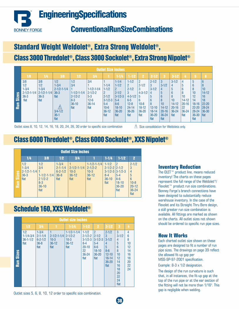
Standard Weight Weldolet®, Extra Strong Weldolet®, Class 3000 Thredolet®, Class 3000 Sockolet®, Extra Strong nipolet®
Class 6000 Thredolet®, Class 6000 Sockolet®, XXS nipolet®
Schedule 160, XXS Weldolet®
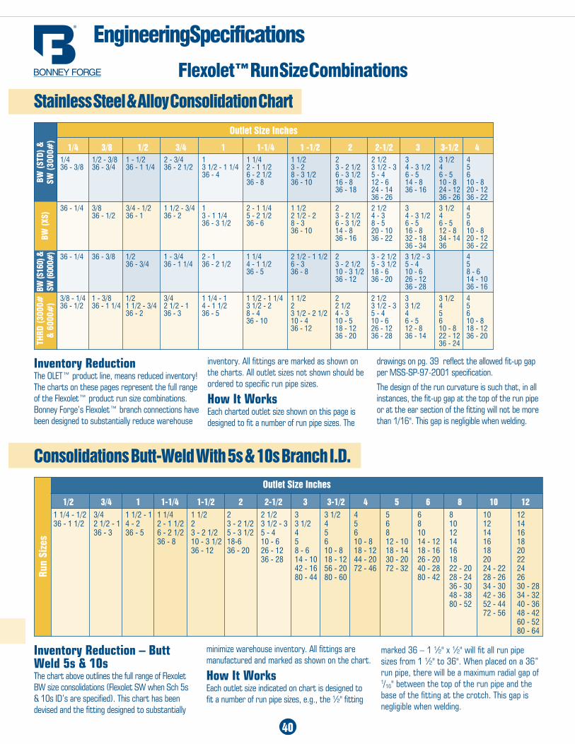
Inventory Reduction The OLET™ product line, means reduced inventory! The charts on these pages represent the full range of the Weldolet®/Flexolet™ product run size combinations. Bonney Forge’s branch connections have been designed to substantially reduce warehouse inventory. In the case of the Flexolet and its Straight Thru Bore design, a still greater run size combination is available. All fittings are marked as shown on the charts. All outlet sizes not shown should be ordered to specific run pipe sizes.
How It Works Each charted outlet size shown on these pages are designed to fit a number of run pipe sizes. The drawings on page 39 reflect the allowed fit-up gap per MSS-SP-97-2001 specification. Example: 8-3 x 1/2 designation.The design of the run curvature is such that, in all instances, the fit-up gap at the top of the run pipe or at the ear section of the fitting will not be more than 1/16". This gap is negligible when welding.
Outlet Size Inches
Run
Size
s
1/4 3/8 1/2 3/4 1 1-1/4 1-1/2 2
1/2 1/2 1-3/4 1 1-1/2-1-1/4 1-1/2 2 2-1/2 1-3/4 3/4 2-1-1/4 2-1/2-1-1/4 2-1/2-2 2-1/2-2 2-1/2 3 2-1/2-1-1/4 1 6-2-1/2 10-3 10-3 3-1/2-3 3-1/2-3 4 36-3 1-1/2-1-1/4 36-8 36-12 36-12 8-4 5-4 5 flat 2 1/2-2 flat flat flat 36-10 8-6 6 8-3 flat 18-10 10-8 36-10 36-20 20-12 flat flat 36-24 flat
Outlet Size Inches
Outlet sizes 8, 10, 12, 14, 16, 18, 20, 24, 26, 30 order to specific size combination
Run
Size
s
1/8 1/4 3/8 1/2 3/4 1 1-1/4 1 -1/2 2 2-1/2 3 3-1/2 4 5 63/8 3/8 1/2 1/2 3/4 1 1-1/4 1-1/2 2 2-1/2 3 3-1/2 4 5 6 1/2 1/2 1-3/4 3/4 1 1-1/4 1-1/2 2 2-1/2 3 3-1/2 4 5 6 8 1-3/4 1-3/4 2-1/2-1-1/4 1 1-1/2-1-1/4 1-1/2 2 2-1/2 3 3-1/2 4 5 6 8 10 2-1/2-1-1/4 2-1/2-1-1/4 36-3 1-1/2-1-1/4 2-1/2-2 2 2-1/2 3 4-3-1/2 4 5 6 8 10 14-12 36-3 36-3 flat 2-1/2-2 5-3 2-1/2 3-1/2-3 4-3-1/2 5 5 6 8 10 12 16 flat flat 8-3 12-6 3-1/2-3 5-4 6-5 6 6 8 10 14-12 14 18 36-10 36-14 5-4 8-6 12-8 10-8 8 10 14-12 20-16 18-16 22-20 1 flat flat 10-6 18-10 24-14 18-12 12-10 14-12 20-16 22 22-20 28-24 3/4-1/2 36-12 36-20 36-26 36-20 18-14 20-16 36-24 36-24 28-24 36-30 36-1 flat flat flat flat 36-20 36-24 flat flat 36-30 flat flat flat flat flat
1 Size consolidation for Weldolets only.
Outlet size Inches
Run
Size
s
Outlet sizes 5, 6, 8, 10, 12 order to specific size combination.
Conventional Run Size Combinations
engineering Specifications
39
engineering Specifications
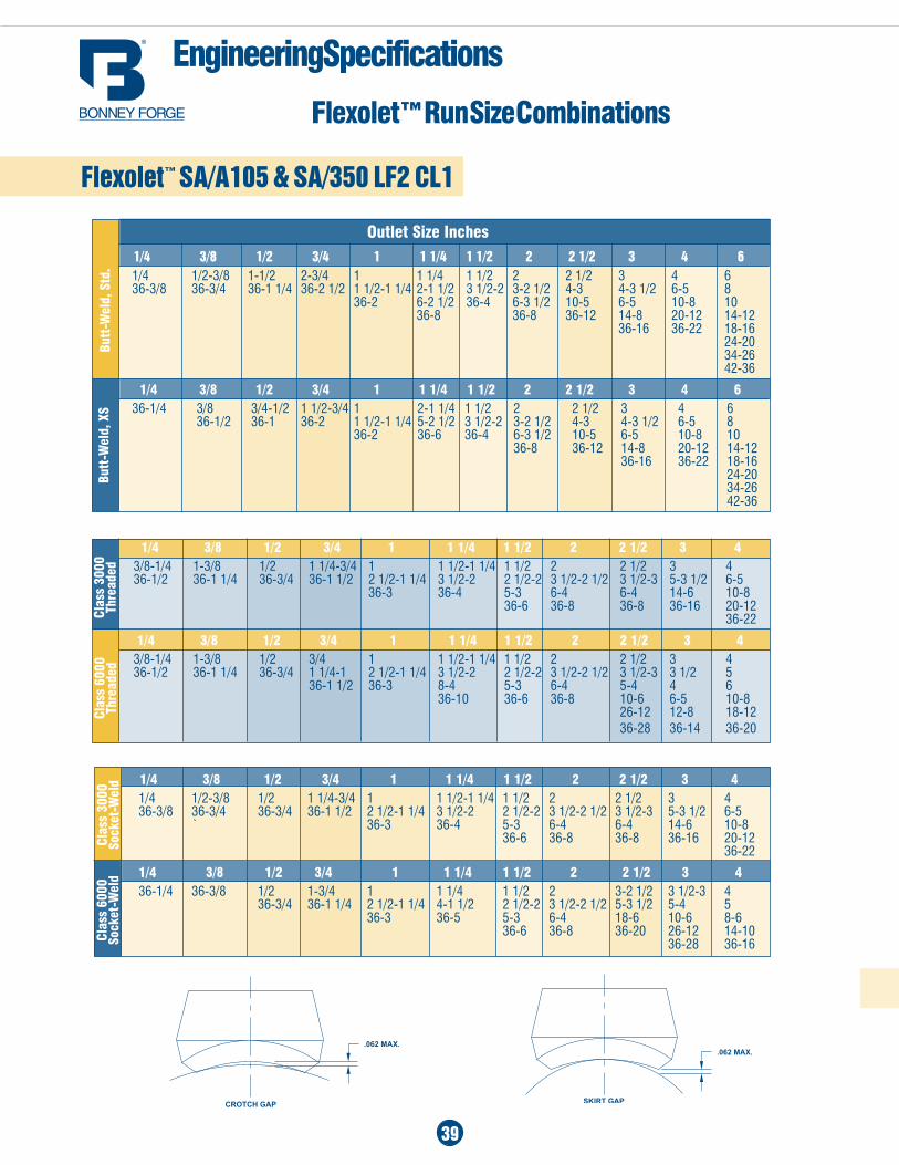
Flexolet™ Run Size Combinations
Flexolet™ Sa/a105 & Sa/350 LF2 CL1
Outlet Size inches
Butt
-Wel
d, S
td.
Clas
s 30
00
Thre
aded
Clas
s 60
00
Thre
aded
1/4 3/8 1/2 3/4 1 1 1/4 1 1/2 2 2 1/2 3 4 6 1/4 1/2-3/8 1-1/2 2-3/4 1 1 1/4 1 1/2 2 2 1/2 3 4 6 36-3/8 36-3/4 36-1 1/4 36-2 1/2 1 1/2-1 1/4 2-1 1/2 3 1/2-2 3-2 1/2 4-3 4-3 1/2 6-5 8 36-2 6-2 1/2 36-4 6-3 1/2 10-5 6-5 10-8 10 36-8 36-8 36-12 14-8 20-12 14-12 36-16 36-22 18-16 24-20 34-26 42-36
1/4 3/8 1/2 3/4 1 1 1/4 1 1/2 2 2 1/2 3 4 6 36-1/4 3/8 3/4-1/2 1 1/2-3/4 1 2-1 1/4 1 1/2 2 2 1/2 3 4 6 36-1/2 36-1 36-2 1 1/2-1 1/4 5-2 1/2 3 1/2-2 3-2 1/2 4-3 4-3 1/2 6-5 8 36-2 36-6 36-4 6-3 1/2 10-5 6-5 10-8 10 36-8 36-12 14-8 20-12 14-12 36-16 36-22 18-16 24-20 34-26 42-36
Clas
s 60
00
Sock
et-W
eld
1/4 3/8 1/2 3/4 1 1 1/4 1 1/2 2 2 1/2 3 4 3/8-1/4 1-3/8 1/2 1 1/4-3/4 1 1 1/2-1 1/4 1 1/2 2 2 1/2 3 4 36-1/2 36-1 1/4 36-3/4 36-1 1/2 2 1/2-1 1/4 3 1/2-2 2 1/2-2 3 1/2-2 1/2 3 1/2-3 5-3 1/2 6-5 36-3 36-4 5-3 6-4 6-4 14-6 10-8 36-6 36-8 36-8 36-16 20-12 36-22
1/4 3/8 1/2 3/4 1 1 1/4 1 1/2 2 2 1/2 3 4 3/8-1/4 1-3/8 1/2 3/4 1 1 1/2-1 1/4 1 1/2 2 2 1/2 3 4 36-1/2 36-1 1/4 36-3/4 1 1/4-1 2 1/2-1 1/4 3 1/2-2 2 1/2-2 3 1/2-2 1/2 3 1/2-3 3 1/2 5 36-1 1/2 36-3 8-4 5-3 6-4 5-4 4 6 36-10 36-6 36-8 10-6 6-5 10-8 26-12 12-8 18-12 36-28 36-14 36-20
1/4 3/8 1/2 3/4 1 1 1/4 1 1/2 2 2 1/2 3 4 1/4 1/2-3/8 1/2 1 1/4-3/4 1 1 1/2-1 1/4 1 1/2 2 2 1/2 3 4 36-3/8 36-3/4 36-3/4 36-1 1/2 2 1/2-1 1/4 3 1/2-2 2 1/2-2 3 1/2-2 1/2 3 1/2-3 5-3 1/2 6-5 ` 36-3 36-4 5-3 6-4 6-4 14-6 10-8 36-6 36-8 36-8 36-16 20-12 36-22
1/4 3/8 1/2 3/4 1 1 1/4 1 1/2 2 2 1/2 3 4 36-1/4 36-3/8 1/2 1-3/4 1 1 1/4 1 1/2 2 3-2 1/2 3 1/2-3 4 36-3/4 36-1 1/4 2 1/2-1 1/4 4-1 1/2 2 1/2-2 3 1/2-2 1/2 5-3 1/2 5-4 5 36-3 36-5 5-3 6-4 18-6 10-6 8-6 36-6 36-8 36-20 26-12 14-10 36-28 36-16
Butt
-Wel
d, X
SCl
ass
3000
So
cket
-Wel
d
40
engineering Specifications
Stainless Steel & alloy Consolidation Chart
Consolidations Butt-Weld With 5s & 10s Branch I.D.Outlet Size Inches
Run
Size
s
1/2 3/4 1 1-1/4 1-1/2 2 2-1/2 3 3-1/2 4 5 6 8 10 121 1/4 - 1/2 3/4 1 1/2 - 1 1 1/4 1 1/2 2 2 1/2 3 3 1/2 4 5 6 8 10 12 36 - 1 1/2 2 1/2 - 1 4 - 2 2 - 1 1/2 2 3 - 2 1/2 3 1/2 - 3 3 1/2 4 5 6 8 10 12 14 36 - 3 36 - 5 6 - 2 1/2 3 - 2 1/2 5 - 3 1/2 5 - 4 4 5 6 8 10 12 14 16 36 - 8 10 - 3 1/2 18-6 10 - 6 5 6 10 - 8 12 - 10 14 - 12 14 16 18 36 - 12 36 - 20 26 - 12 8 - 6 10 - 8 18 - 12 18 - 14 18 - 16 16 18 20 36 - 28 14 - 10 18 - 12 44 - 20 30 - 20 26 - 20 18 20 22 42 - 16 56 - 20 72 - 46 72 - 32 40 - 28 22 - 20 24 - 22 24 80 - 44 80 - 60 80 - 42 28 - 24 28 - 26 26 36 - 30 34 - 30 30 - 28 48 - 38 42 - 36 34 - 32 80 - 52 52 - 44 40 - 36 72 - 56 48 - 42 60 - 52 80 - 64
Outlet Size Inches
BW (
STd)
&
SW (
3000
#)
1/4 3/8 1/2 3/4 1 1-1/4 1 -1/2 2 2-1/2 3 3-1/2 41/4 1/2 - 3/8 1 - 1/2 2 - 3/4 1 1 1/4 1 1/2 2 2 1/2 3 3 1/2 4 36 - 3/8 36 - 3/4 36 - 1 1/4 36 - 2 1/2 3 1/2 - 1 1/4 2 - 1 1/2 3 - 2 3 - 2 1/2 3 1/2 - 3 4 - 3 1/2 4 5 36 - 4 6 - 2 1/2 8 - 3 1/2 6 - 3 1/2 5 - 4 6 - 5 6 - 5 6 36 - 8 36 - 10 16 - 8 12 - 6 14 - 8 10 - 8 10 - 8 36 - 18 24 - 14 36 - 16 24 - 12 20 - 12 36 - 26 36 - 26 36 - 2236 - 1/4 3/8 3/4 - 1/2 1 1/2 - 3/4 1 2 - 1 1/4 1 1/2 2 2 1/2 3 3 1/2 4 36 - 1/2 36 - 1 36 - 2 3 - 1 1/4 5 - 2 1/2 2 1/2 - 2 3 - 2 1/2 4 - 3 4 - 3 1/2 4 5 36 - 3 1/2 36 - 6 8 - 3 6 - 3 1/2 8 - 5 6 - 5 6 - 5 6 36 - 10 14 - 8 20 - 10 16 - 8 12 - 8 10 - 8 36 - 16 36 - 22 32 - 18 34 - 14 20 - 12 36 - 34 36 36 - 2236 - 1/4 36 - 3/8 1/2 1 - 3/4 2 - 1 1 1/4 2 1/2 - 1 1/2 2 3 - 2 1/2 3 1/2 - 3 4 36 - 3/4 36 - 1 1/4 36 - 2 1/2 4 - 1 1/2 6 - 3 3 - 2 1/2 5 - 3 1/2 5 - 4 5 36 - 5 36 - 8 10 - 3 1/2 18 - 6 10 - 6 8 - 6 36 - 12 36 - 20 26 - 12 14 - 10 36 - 28 36 - 16
3/8 - 1/4 1 - 3/8 1/2 3/4 1 1/4 - 1 1 1/2 - 1 1/4 1 1/2 2 2 1/2 3 3 1/2 4 36 - 1/2 36 - 1 1/4 1 1/2 - 3/4 2 1/2 - 1 4 - 1 1/2 3 1/2 - 2 2 2 1/2 3 1/2 - 3 3 1/2 4 5 36 - 2 36 - 3 36 - 5 8 - 4 3 1/2 - 2 1/2 4 - 3 5 - 4 4 5 6 36 - 10 10 - 4 10 - 5 10 - 6 6 - 5 6 10 - 8 36 - 12 18 - 12 26 - 12 12 - 8 10 - 8 18 - 12 36 - 20 36 - 28 36 - 14 22 - 12 36 - 20 36 - 24
BW (
XS)
BW (S
160)
&
SW (6
000#
)Th
Rd (
3000
#
& 6
000#
)
Flexolet™ Run Size Combinations
Inventory Reduction The OLET™ product line, means reduced inventory! The charts on these pages represent the full range of the Flexolet™ product run size combinations. Bonney Forge’s Flexolet™ branch connections have been designed to substantially reduce warehouse
Inventory Reduction – Butt Weld 5s & 10sThe chart above outlines the full range of Flexolet BW size consolidations (Flexolet SW when Sch 5s & 10s ID’s are specified). This chart has been devised and the fitting designed to substantially
minimize warehouse inventory. All fittings are manufactured and marked as shown on the chart.
How It WorksEach outlet size indicated on chart is designed to fit a number of run pipe sizes, e.g., the ½" fitting
marked 36 – 1 ½" x ½" will fit all run pipe sizes from 1 ½" to 36". When placed on a 36” run pipe, there will be a maximum radial gap of
1/16" between the top of the run pipe and the base of the fitting at the crotch. This gap is negligible when welding.
inventory. All fittings are marked as shown on the charts. All outlet sizes not shown should be ordered to specific run pipe sizes.
How It Works Each charted outlet size shown on this page is designed to fit a number of run pipe sizes. The
drawings on pg. 39 reflect the allowed fit-up gap per MSS-SP-97-2001 specification.
The design of the run curvature is such that, in all instances, the fit-up gap at the top of the run pipe or at the ear section of the fitting will not be more than 1/16". This gap is negligible when welding.
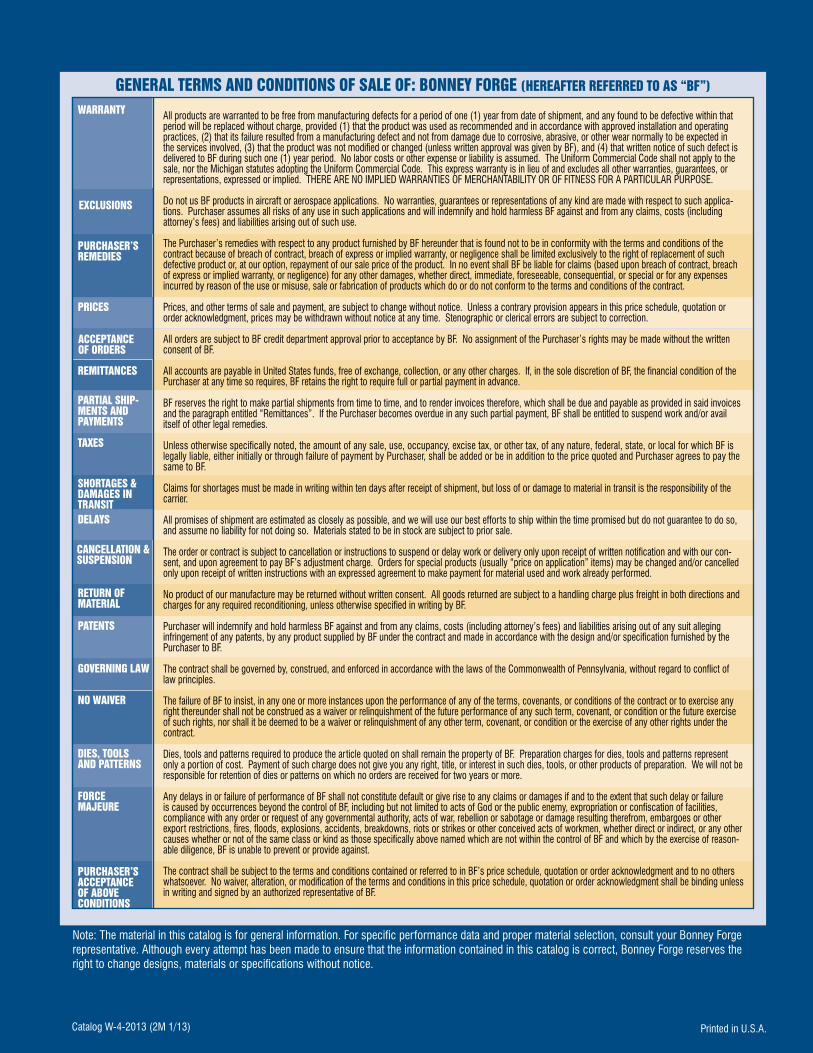
PaTEnTS
gOVERnIng LaW
gEnERaL TERMS anD COnDITIOnS OF SaLE OF: BOnnEY FORgE (HEREaFTER REFERRED TO aS “BF”) WaRRanTY
EXCLUSIOnS
PURCHaSER’S REMEDIES
PRICES
aCCEPTanCE OF ORDERS
REMITTanCES
TaXES
SHORTagES & DaMagES In TRanSITDELaYS
CanCELLaTIOn & SUSPEnSIOn
RETURn OF MaTERIaL
nO WaIVER
DIES, TOOLS anD PaTTERnS
FORCE MaJEURE
PURCHaSER’S aCCEPTanCE OF aBOVE COnDITIOnS
PaRTIaL SHIP-MEnTS anD PaYMEnTS
Note: The material in this catalog is for general information. For specific performance data and proper material selection, consult your Bonney Forge representative. although every attempt has been made to ensure that the information contained in this catalog is correct, Bonney Forge reserves the right to change designs, materials or specifications without notice.
Printed in U.S.a.Catalog W-4-2013 (2M 1/13)
all products are warranted to be free from manufacturing defects for a period of one (1) year from date of shipment, and any found to be defective within that period will be replaced without charge, provided (1) that the product was used as recommended and in accordance with approved installation and operating practices, (2) that its failure resulted from a manufacturing defect and not from damage due to corrosive, abrasive, or other wear normally to be expected in the services involved, (3) that the product was not modified or changed (unless written approval was given by BF), and (4) that written notice of such defect is delivered to BF during such one (1) year period. No labor costs or other expense or liability is assumed. The Uniform Commercial Code shall not apply to the sale, nor the Michigan statutes adopting the Uniform Commercial Code. This express warranty is in lieu of and excludes all other warranties, guarantees, or representations, expressed or implied. THERE aRE NO IMPLIED WaRRaNTIES OF MERCHaNTaBILITY OR OF FITNESS FOR a PaRTICULaR PURPOSE.
Do not us BF products in aircraft or aerospace applications. No warranties, guarantees or representations of any kind are made with respect to such applica-tions. Purchaser assumes all risks of any use in such applications and will indemnify and hold harmless BF against and from any claims, costs (including attorney’s fees) and liabilities arising out of such use.
The Purchaser’s remedies with respect to any product furnished by BF hereunder that is found not to be in conformity with the terms and conditions of the contract because of breach of contract, breach of express or implied warranty, or negligence shall be limited exclusively to the right of replacement of such defective product or, at our option, repayment of our sale price of the product. In no event shall BF be liable for claims (based upon breach of contract, breach of express or implied warranty, or negligence) for any other damages, whether direct, immediate, foreseeable, consequential, or special or for any expenses incurred by reason of the use or misuse, sale or fabrication of products which do or do not conform to the terms and conditions of the contract.
Prices, and other terms of sale and payment, are subject to change without notice. Unless a contrary provision appears in this price schedule, quotation or order acknowledgment, prices may be withdrawn without notice at any time. Stenographic or clerical errors are subject to correction.
all orders are subject to BF credit department approval prior to acceptance by BF. No assignment of the Purchaser’s rights may be made without the written consent of BF.
all accounts are payable in United States funds, free of exchange, collection, or any other charges. If, in the sole discretion of BF, the financial condition of the Purchaser at any time so requires, BF retains the right to require full or partial payment in advance.
BF reserves the right to make partial shipments from time to time, and to render invoices therefore, which shall be due and payable as provided in said invoices and the paragraph entitled “Remittances”. If the Purchaser becomes overdue in any such partial payment, BF shall be entitled to suspend work and/or avail itself of other legal remedies.
Unless otherwise specifically noted, the amount of any sale, use, occupancy, excise tax, or other tax, of any nature, federal, state, or local for which BF is legally liable, either initially or through failure of payment by Purchaser, shall be added or be in addition to the price quoted and Purchaser agrees to pay the same to BF.
Claims for shortages must be made in writing within ten days after receipt of shipment, but loss of or damage to material in transit is the responsibility of the carrier.
all promises of shipment are estimated as closely as possible, and we will use our best efforts to ship within the time promised but do not guarantee to do so, and assume no liability for not doing so. Materials stated to be in stock are subject to prior sale.
The order or contract is subject to cancellation or instructions to suspend or delay work or delivery only upon receipt of written notification and with our con-sent, and upon agreement to pay BF’s adjustment charge. Orders for special products (usually “price on application” items) may be changed and/or cancelled only upon receipt of written instructions with an expressed agreement to make payment for material used and work already performed.
No product of our manufacture may be returned without written consent. all goods returned are subject to a handling charge plus freight in both directions and charges for any required reconditioning, unless otherwise specified in writing by BF.
Purchaser will indemnify and hold harmless BF against and from any claims, costs (including attorney’s fees) and liabilities arising out of any suit alleging infringement of any patents, by any product supplied by BF under the contract and made in accordance with the design and/or specification furnished by the Purchaser to BF.
The contract shall be governed by, construed, and enforced in accordance with the laws of the Commonwealth of Pennsylvania, without regard to conflict of law principles.
The failure of BF to insist, in any one or more instances upon the performance of any of the terms, covenants, or conditions of the contract or to exercise any right thereunder shall not be construed as a waiver or relinquishment of the future performance of any such term, covenant, or condition or the future exercise of such rights, nor shall it be deemed to be a waiver or relinquishment of any other term, covenant, or condition or the exercise of any other rights under the contract.
Dies, tools and patterns required to produce the article quoted on shall remain the property of BF. Preparation charges for dies, tools and patterns represent only a portion of cost. Payment of such charge does not give you any right, title, or interest in such dies, tools, or other products of preparation. We will not be responsible for retention of dies or patterns on which no orders are received for two years or more.
any delays in or failure of performance of BF shall not constitute default or give rise to any claims or damages if and to the extent that such delay or failure is caused by occurrences beyond the control of BF, including but not limited to acts of God or the public enemy, expropriation or confiscation of facilities, compliance with any order or request of any governmental authority, acts of war, rebellion or sabotage or damage resulting therefrom, embargoes or other export restrictions, fires, floods, explosions, accidents, breakdowns, riots or strikes or other conceived acts of workmen, whether direct or indirect, or any other causes whether or not of the same class or kind as those specifically above named which are not within the control of BF and which by the exercise of reason-able diligence, BF is unable to prevent or provide against.
The contract shall be subject to the terms and conditions contained or referred to in BF’s price schedule, quotation or order acknowledgment and to no others whatsoever. No waiver, alteration, or modification of the terms and conditions in this price schedule, quotation or order acknowledgment shall be binding unless in writing and signed by an authorized representative of BF.