Embed Size (px)
Citation preview

Final Thesis
Boundary-Scan in the ATCA standardby
David Bäckström
LITH-IDA/DS-EX--05/008--SE
2005-06-07

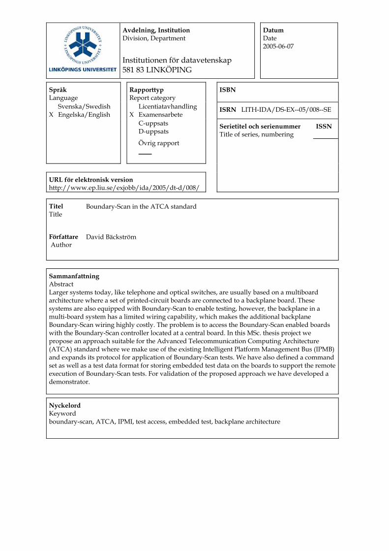
Avdelning, Institution Division, Department
Institutionen för datavetenskap 581 83 LINKÖPING
Datum Date 2005-06-07
Språk Language
Rapporttyp Report category
ISBN
Svenska/Swedish X Engelska/English
Licentiatavhandling X Examensarbete
ISRN LITH-IDA/DS-EX--05/008--SE
C-uppsats D-uppsats
Serietitel och serienummer Title of series, numbering
ISSN
Övrig rapport ____
URL för elektronisk version http://www.ep.liu.se/exjobb/ida/2005/dt-d/008/
Titel Title
Boundary-Scan in the ATCA standard
Författare Author
David Bäckström
Sammanfattning Abstract Larger systems today, like telephone and optical switches, are usually based on a multiboard architecture where a set of printed-circuit boards are connected to a backplane board. These systems are also equipped with Boundary-Scan to enable testing, however, the backplane in a multi-board system has a limited wiring capability, which makes the additional backplane Boundary-Scan wiring highly costly. The problem is to access the Boundary-Scan enabled boards with the Boundary-Scan controller located at a central board. In this MSc. thesis project we propose an approach suitable for the Advanced Telecommunication Computing Architecture (ATCA) standard where we make use of the existing Intelligent Platform Management Bus (IPMB) and expands its protocol for application of Boundary-Scan tests. We have also defined a command set as well as a test data format for storing embedded test data on the boards to support the remote execution of Boundary-Scan tests. For validation of the proposed approach we have developed a demonstrator.
Nyckelord Keyword boundary-scan, ATCA, IPMI, test access, embedded test, backplane architecture

Linköpings universitetDepartment of Computer and Information Science
Final Thesis
Boundary-Scan in the ATCA standardby
David Bäckström
LITH-IDA/DS-EX--05/008--SE
2005-06-07
Supervisor: Gunnar Carlsson Ericsson ABExaminer: Erik Larsson Linköping Institute of Technology

14 June 2005 i
Abstract
Larger systems today, like telephone and optical switches, are usually based on a multi-board architecture where a set of printed-circuit boards are connected to a backplane board. These systems are also equipped with Boundary-Scan to enable testing, how-ever, the backplane in a multi-board system has a limited wiring capability, which makes the additional backplane Boundary-Scan wiring highly costly. The problem is to access the Boundary-Scan enabled boards with the Boundary-Scan controller located at a central board. In this MSc. thesis project we propose an approach suitable for the Advanced Telecommunication Computing Architecture (ATCA) standard where we make use of the existing Intelligent Platform Management Bus (IPMB) and expands its protocol for application of Boundary-Scan tests. We have also defined a command set as well as a test data format for storing embedded test data on the boards to support the remote execution of Boundary-Scan tests. For validation of the proposed approach we have developed a demonstrator.

14 June 2005 ii
14 June 2005 iii
Acknowledgement
First of all I wish to thank Ericsson AB and ESLAB for giving me the opportunity to work on this thesis project. Special thanks to my supervisors Gunnar Carlsson and Erik Larsson for their excellent supervision and for sharing their great experience with me. Your support have been invaluable.
I would also like to thank Ken Filliter, Bill Aronson, and Magnus Eckersand at National Semiconductor for supplying the Scanease software and hardware compo-nents. Without your support, this work would have been impossible. My gratitude also to Atmel for your generosity of the supplied microcontrollers.
Finally I would like to thank all my friends and loved ones that have supported me dur-ing this work, and Erik Alfredsson, your skill in the electronics lab is unmatched.
This thesis ends my studies at the Applied physics and Electrical engineering program at Linköpings University. I would like to thank all my friends, teachers and others who have made these years fun and interesting.

14 June 2005 iv
14 June 2005 v
Contents1.0 Introduction........................................................................................................ 1
2.0 Background........................................................................................................ 32.1 System description ........................................................................................................ 32.2 Boundary-Scan Testing ............................................................................................... 12
3.0 Problem Definition .......................................................................................... 213.1 Backplane and Linkage ............................................................................................... 213.2 Command set and Embedded data format................................................................... 213.3 Project Goals ............................................................................................................... 223.4 System Backdoor......................................................................................................... 22
4.0 Related work.................................................................................................... 254.1 Boundary-Scan Architecture and Protocol.................................................................. 254.2 Boundary-Scan Architecture and Extended Protocol.................................................. 254.3 Alternatives to Boundary-Scan ................................................................................... 26
5.0 Approach.......................................................................................................... 295.1 The Added Boundary-Scan Functionality ................................................................... 295.2 The Extended IPMB Protocol ..................................................................................... 305.3 The Command Set ....................................................................................................... 375.4 The Binary Vector Format ........................................................................................... 39
6.0 Demonstration board ....................................................................................... 416.1 Board Overview .......................................................................................................... 416.2 Hardware Layout ......................................................................................................... 436.3 Software Structure ....................................................................................................... 446.4 Commands and Features ............................................................................................. 45
7.0 Experimental Results ....................................................................................... 497.1 IPMB Performance...................................................................................................... 497.2 Transport time computation......................................................................................... 497.3 System Example .......................................................................................................... 51
8.0 Future Work ..................................................................................................... 55
9.0 Conclusion ....................................................................................................... 57
10.0 References........................................................................................................ 59

14 June 2005 1
1.0 Introduction
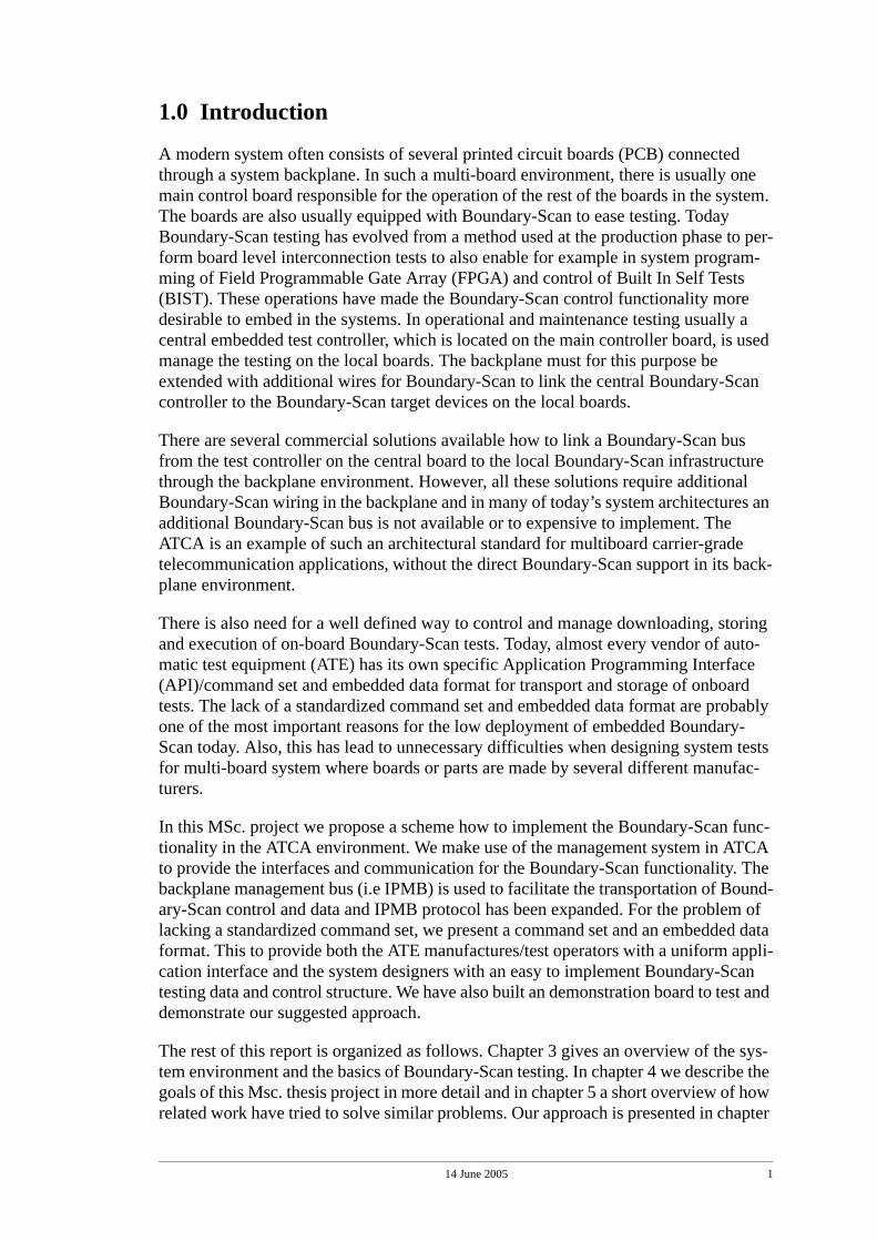
A modern system often consists of several printed circuit boards (PCB) connected through a system backplane. In such a multi-board environment, there is usually one main control board responsible for the operation of the rest of the boards in the system. The boards are also usually equipped with Boundary-Scan to ease testing. Today Boundary-Scan testing has evolved from a method used at the production phase to per-form board level interconnection tests to also enable for example in system program-ming of Field Programmable Gate Array (FPGA) and control of Built In Self Tests (BIST). These operations have made the Boundary-Scan control functionality more desirable to embed in the systems. In operational and maintenance testing usually a central embedded test controller, which is located on the main controller board, is used manage the testing on the local boards. The backplane must for this purpose be extended with additional wires for Boundary-Scan to link the central Boundary-Scan controller to the Boundary-Scan target devices on the local boards.
There are several commercial solutions available how to link a Boundary-Scan bus from the test controller on the central board to the local Boundary-Scan infrastructure through the backplane environment. However, all these solutions require additional Boundary-Scan wiring in the backplane and in many of today’s system architectures an additional Boundary-Scan bus is not available or to expensive to implement. The ATCA is an example of such an architectural standard for multiboard carrier-grade telecommunication applications, without the direct Boundary-Scan support in its back-plane environment.
There is also need for a well defined way to control and manage downloading, storing and execution of on-board Boundary-Scan tests. Today, almost every vendor of auto-matic test equipment (ATE) has its own specific Application Programming Interface (API)/command set and embedded data format for transport and storage of onboard tests. The lack of a standardized command set and embedded data format are probably one of the most important reasons for the low deployment of embedded Boundary-Scan today. Also, this has lead to unnecessary difficulties when designing system tests for multi-board system where boards or parts are made by several different manufac-turers.
In this MSc. project we propose a scheme how to implement the Boundary-Scan func-tionality in the ATCA environment. We make use of the management system in ATCA to provide the interfaces and communication for the Boundary-Scan functionality. The backplane management bus (i.e IPMB) is used to facilitate the transportation of Bound-ary-Scan control and data and IPMB protocol has been expanded. For the problem of lacking a standardized command set, we present a command set and an embedded data format. This to provide both the ATE manufactures/test operators with a uniform appli-cation interface and the system designers with an easy to implement Boundary-Scan testing data and control structure. We have also built an demonstration board to test and demonstrate our suggested approach.
The rest of this report is organized as follows. Chapter 3 gives an overview of the sys-tem environment and the basics of Boundary-Scan testing. In chapter 4 we describe the goals of this Msc. thesis project in more detail and in chapter 5 a short overview of how related work have tried to solve similar problems. Our approach is presented in chapter

14 June 2005 2
6 and in chapter 7 we describe the demonstration board. In chapter 8 some calculations are made to describe the performance of the IPMB when transporting Boundary-Scan data and control and in chapter 9 we discuss where improvements can be made in future work. The report is concluded in chapter 10.
14 June 2005 3
2.0 Background
In this chapter we will describe the basics of the system architecture and the basics of the boundary-scan testing technique.
2.1 System description
The systems, which this project is mainly aimed at, are larger network and telecommu-nication applications like telephone and optical switches. The complexity of these sys-tems has during the last years grown rapidly and manufacturers have been seeking new ways to reduce the burden of the development. One way to do this is to let other com-panies (third parties) develop and manufacture parts on a system level which then can be purchased and implemented, similar to the PC-industry today. To accomplish this several parameters need to be standardized like interfaces and physical dimensions. This was why PICMG 3.0 Advance Telecommunication Computing Architecture (ATCA) [6] was developed and is today being increasingly deployed in new systems.
In the following sub chapters we will focus on describing each part of the system that concerns this projects work. We start at the highest level of abstraction with ATCA and down to the hardware aspects of the I2C Bus [10].
2.1.1 ATCA
In this section will describe the main characteristics of ATCA.
The PICMG 3.0 Advance Telecommunication Computing Architecture (ATCA) speci-fies an open architecture with modular components that quickly can be integrated into a larger systems to improve serviceability.
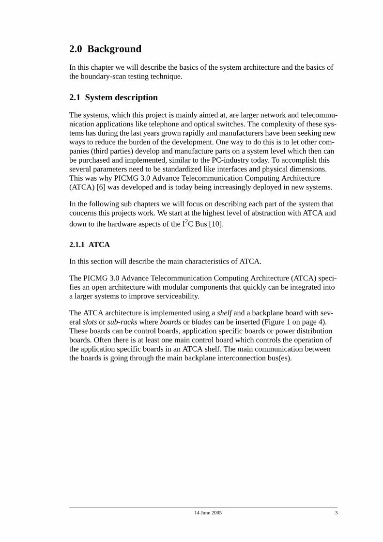
The ATCA architecture is implemented using a shelf and a backplane board with sev-eral slots or sub-racks where boards or blades can be inserted (Figure 1 on page 4). These boards can be control boards, application specific boards or power distribution boards. Often there is at least one main control board which controls the operation of the application specific boards in an ATCA shelf. The main communication between the boards is going through the main backplane interconnection bus(es).
14 June 2005 4
FIGURE 1. Multi board system
ATCA contain design specifications and requirements in the following areas:
• Mechanical and dimensions
• Power distribution
• Thermal dissipation
• Interfacing and communication
• System management
This project will focus on the system management part of ATCA. The system manage-ment in ATCA is based upon a distributed system of localized management controllers. The management system in ATCA is called Intelligent Platform Management Interface (IPMI) architecture [7].
2.1.2 IPMI
In this section we will describe the Intelligent Platform Management Interface (IPMI) that provides communication, management and control among the locally distributed management controllers and to a supervising system manager. IPMI autonomously provides inventory, monitoring, logging and recovery control, and exposing those functions to the OS and/or the management software.
IPMI is independent of the systems main processor, which means that management function can be made available when the system is not operating, like in a power down state or if a fault has occurred which has forced parts of the system to halt.
14 June 2005 5
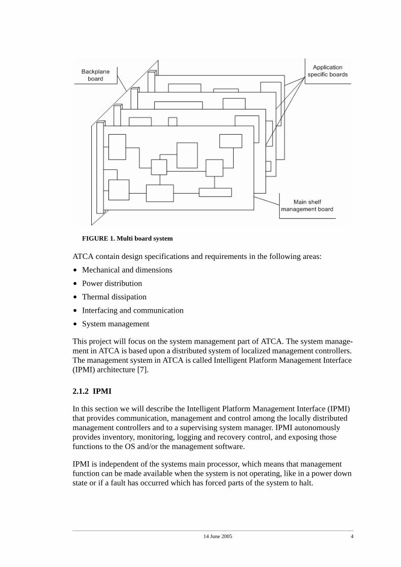
FIGURE 2. Management setup in an ATCA shelf
The heart of IPMI is the network of Baseboard Management Controllers (BMC, aka Intelligent Platform Management Controllers, IPMC) which provide the Intelligence in IPMI. These BMC units handles the interface between system management software and the management hardware components. Such HW components could typically be temperature sensors or fan controllers. In a typical ATCA-system where several appli-cation specific boards are in use simultaneously in a shelf, one or more BMC units are placed on each application board and one central BMC or a Shelf Management Con-troller (ShMC aka Shelf Manager, SM) on a controller board (Figure 2 on page 5). This SM unit then controls the operation of the slave BMC units and provides the interface to the system management software or Operating System. The communication between the controllers is handled by the Intelligent Platform Management Bus (IPMB) [8].
14 June 2005 6
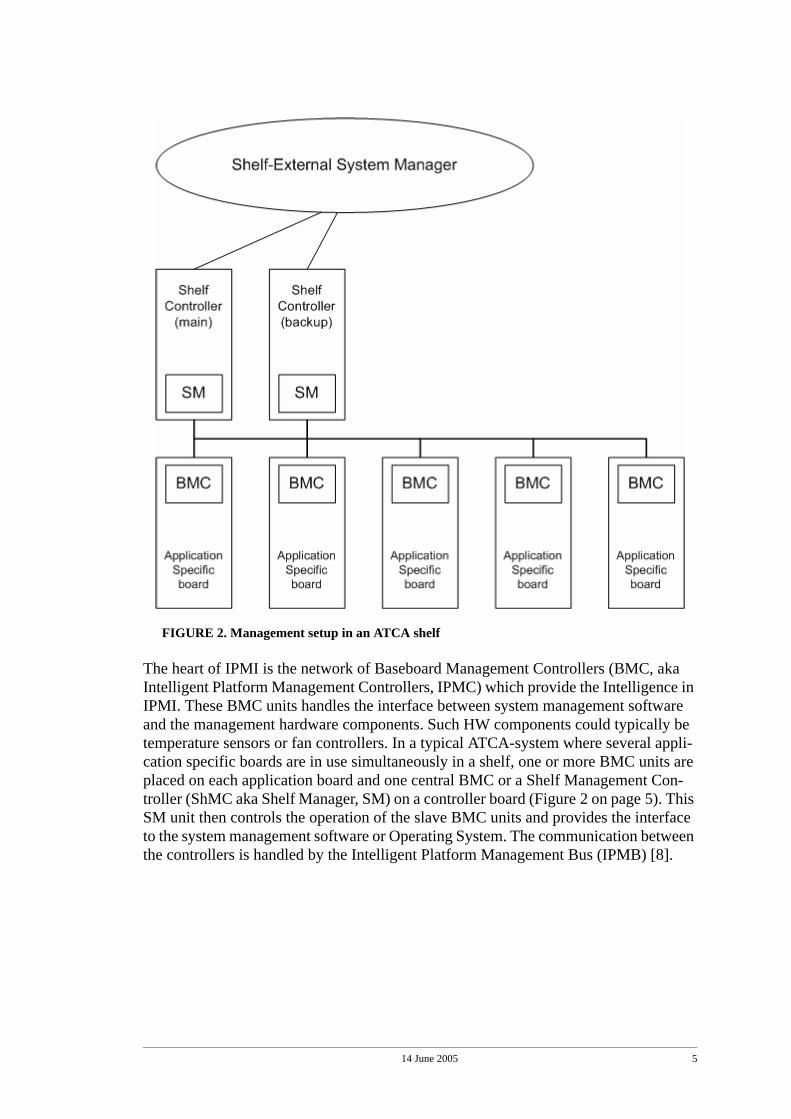
FIGURE 3. Example of the internal structure of an IPMC slave unit.
Figure 3 shows an example of the internal structure of an BMC slave unit. A BMC can have a single or several functions. The IPMI specification does not specify this. Note that IPMI is mainly a framework for implementation of additional management func-tions in a system. It provides the interfaces and means of communication within the system for the new management functionality. It is this feature of IPMI that our project aims at to utilise in order to implement the Boundary-Scan functionality.
2.1.3 IPMB
In this section we will describe the Intelligent Platform Management Bus (IPMB) and its protocol specification.
The main purpose of the IPMB is to support the “Intelligent Platform Management”, described in the previous section, by providing a well defined bus structure and a corre-sponding protocol. Several goals has been addressed by IPMB to achieve this:
• Support of a distributed management architecture where intelligent and non-intelli-gent sensors and controllers are placed on local management modules. This will result in a more flexible architecture compared to if every controller and sensor where directly linked to one central controller.
• Provide a straight forward way to add new management controllers to the IPMB without imposing side-effects to the other controllers on the bus. This will make it easier to expand a system with new functions and modules. It also enables third par-ties to develop extensions as long as they follow the IPMB specification.
• The multi-master architecture of the I2C-bus on which IPMB is based upon enables the controllers to send asynchronous event messages. For example a critical error event if a module is malfunctioning.
• The low hardware requirements of the I2C-bus, on which IPMB is based upon, pro-vides an inexpensive and a low IC-pin count1 communication media. And since the
14 June 2005 7
IPMB is separated from the systems memory and processor buses, the communica-tion and operation of IPMI can continue even if a failure prevents the rest of the sys-tem to run.
Today system designers usually limits the number of intelligent controllers connected to one IPMB to 15 nodes. This to keep the load on the bus as low as possible as a typi-cal IPMI-controller sends 6 messages per second on average over the bus. Note that 15 nodes are not a specified limit of the specification, only a recommendation. The physi-cal limitations of the number of nodes on IPMB are described in the I2C-bus section (See “I2C-bus” on page 10.) [10].
The IPMB protocol uses a request/response mechanism where each intelligent control-ler on the bus that receives a request message must respond with a response message. Requests and responses are not automatically paired transactions, other transactions are allowed in between them. However, a IPMB node does not need to queue incoming requests or responses when it is processing other messages, it can elect to not accept (not acknowledge) the message and let the sender node retry later. The advantage of this is that it will make the implementation easier in smaller controllers. Note that the IPMI nor the IPMB specification do not specify how this functionality should be implemented.
We will now describe the message format specified in IPMB, it consists of a connec-tion header and the command and data bytes required for a transaction.
The message format is divided into blocks where each block is 1 byte in size. This because when sent on the I2C-bus the data is sent one byte at a time and each byte is either accepted or not accepted by the receiver (See the “acknowledge and not-acknowledge” section in “I2C-bus” on page 10).
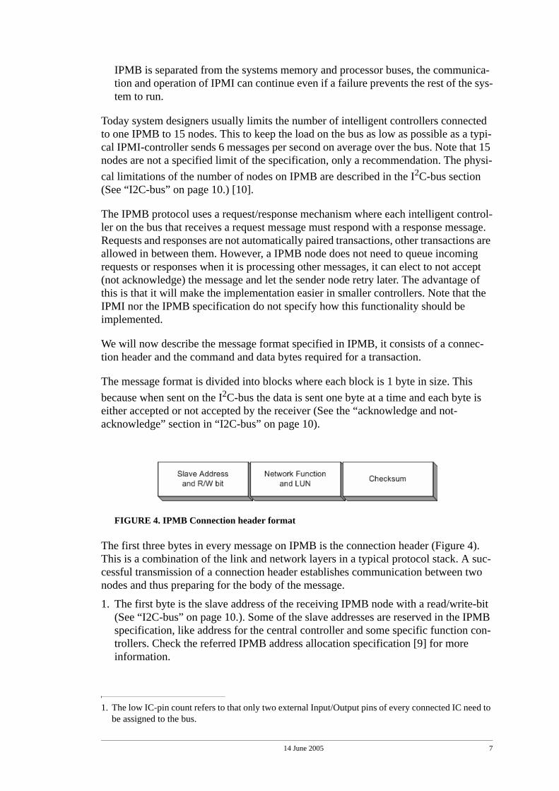
FIGURE 4. IPMB Connection header format
The first three bytes in every message on IPMB is the connection header (Figure 4). This is a combination of the link and network layers in a typical protocol stack. A suc-cessful transmission of a connection header establishes communication between two nodes and thus preparing for the body of the message.
1. The first byte is the slave address of the receiving IPMB node with a read/write-bit (See “I2C-bus” on page 10.). Some of the slave addresses are reserved in the IPMB specification, like address for the central controller and some specific function con-trollers. Check the referred IPMB address allocation specification [9] for more information.
1. The low IC-pin count refers to that only two external Input/Output pins of every connected IC need to be assigned to the bus.
14 June 2005 8
2. The second byte is the network function and a Logical Unit Number (LUN). The network function is used to cluster commands into functional command sets and the LUN provides a way to address sub-units within a IPMB node. Also, the network function can be used to tell requests from responses, requests use even-numbered network function values and response uses odd-numbered values.
3. The third byte, and the last in the connection header is the checksum byte. The checksum is used to verify the data integrity of the connection header. If the check-sum does not verify, a node can reject the rest of the message since it is uncertain if even the slave address is correct, and then uncertain that the message was delivered to the correct node in the first place.
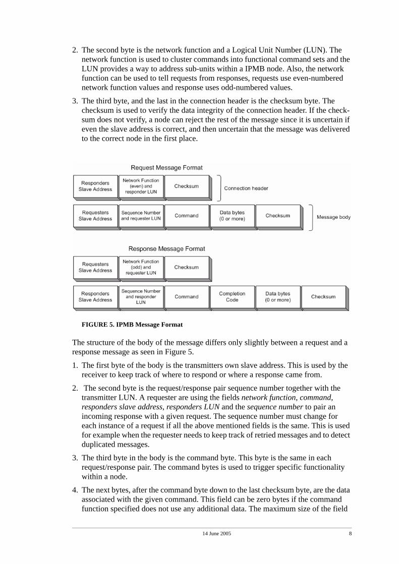
FIGURE 5. IPMB Message Format
The structure of the body of the message differs only slightly between a request and a response message as seen in Figure 5.
1. The first byte of the body is the transmitters own slave address. This is used by the receiver to keep track of where to respond or where a response came from.
2. The second byte is the request/response pair sequence number together with the transmitter LUN. A requester are using the fields network function, command, responders slave address, responders LUN and the sequence number to pair an incoming response with a given request. The sequence number must change for each instance of a request if all the above mentioned fields is the same. This is used for example when the requester needs to keep track of retried messages and to detect duplicated messages.
3. The third byte in the body is the command byte. This byte is the same in each request/response pair. The command bytes is used to trigger specific functionality within a node.
4. The next bytes, after the command byte down to the last checksum byte, are the data associated with the given command. This field can be zero bytes if the command function specified does not use any additional data. The maximum size of the field
14 June 2005 9
is 25 bytes in a request message and 24 bytes in a response. It is also here that struc-ture of the request and response differs, in a response message the first byte after the command byte is a completion code, which can tell the requester if the request was completed successfully and if not, what went wrong.
5. The last byte in the body and in the massage is the checksum. If this does not vali-date the message can be ignored.
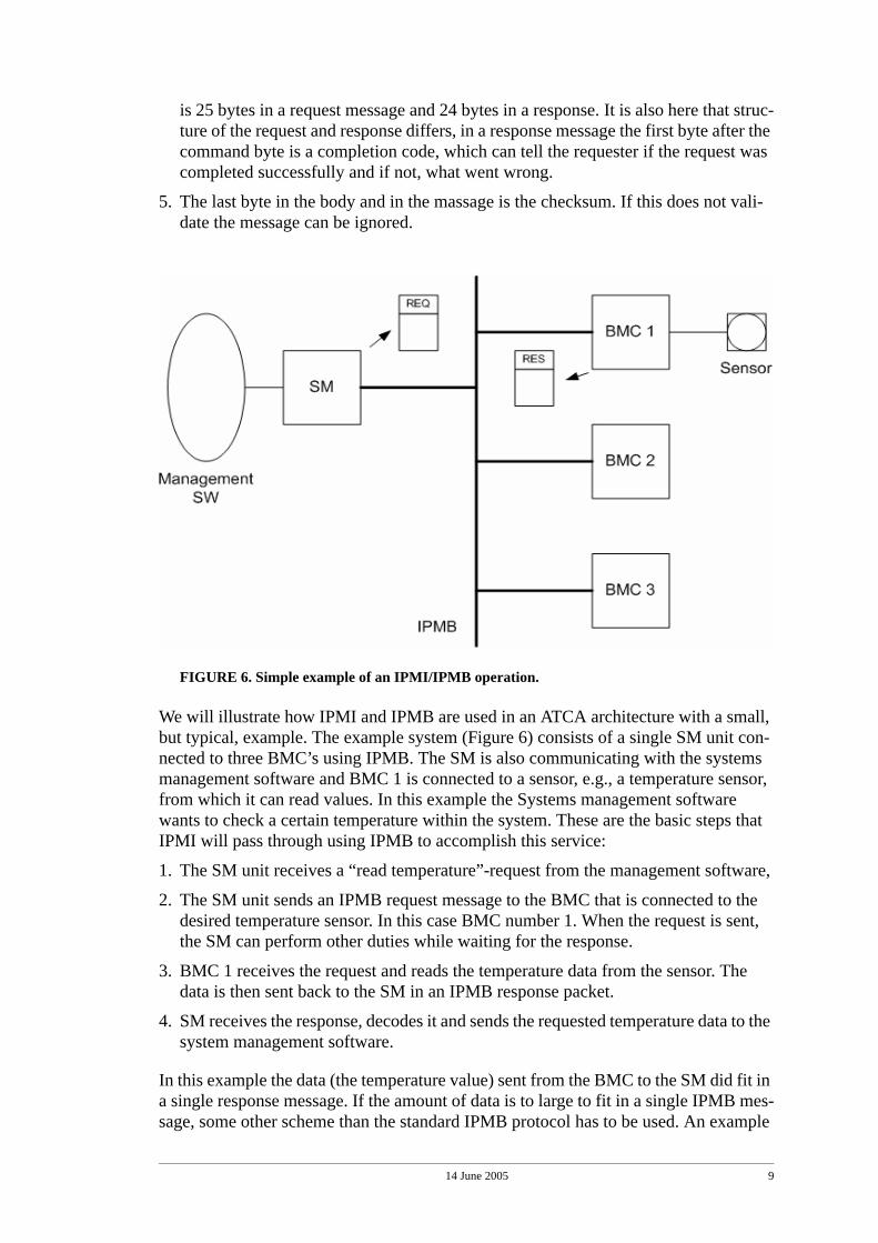
FIGURE 6. Simple example of an IPMI/IPMB operation.
We will illustrate how IPMI and IPMB are used in an ATCA architecture with a small, but typical, example. The example system (Figure 6) consists of a single SM unit con-nected to three BMC’s using IPMB. The SM is also communicating with the systems management software and BMC 1 is connected to a sensor, e.g., a temperature sensor, from which it can read values. In this example the Systems management software wants to check a certain temperature within the system. These are the basic steps that IPMI will pass through using IPMB to accomplish this service:
1. The SM unit receives a “read temperature”-request from the management software,
2. The SM unit sends an IPMB request message to the BMC that is connected to the desired temperature sensor. In this case BMC number 1. When the request is sent, the SM can perform other duties while waiting for the response.
3. BMC 1 receives the request and reads the temperature data from the sensor. The data is then sent back to the SM in an IPMB response packet.
4. SM receives the response, decodes it and sends the requested temperature data to the system management software.
In this example the data (the temperature value) sent from the BMC to the SM did fit in a single response message. If the amount of data is to large to fit in a single IPMB mes-sage, some other scheme than the standard IPMB protocol has to be used. An example
14 June 2005 10
of such will be described later in this report (See “Approach” on page 29.) to transport larger Boundary-Scan test files.
2.1.4 I2C-bus
In this section we will describe the I2C-bus [10] and it is implementation on which the IPMB is based on. We will focus on the parts of the specification that concerns IPMB.
The Inter IC bus or I2C-bus is a serial, bi-directional 2-wire bus developed by Philips which released version 1.0 of its specification in 1992. Today the usage is widely spread especially in systems were a low IC pin count and a reduced number of PCB-tracks1 is required. It can not compete in data transfers rate with parallel buses but is well suited for control functions in embedded systems.
The data rates of the I2C-bus is up to 100 kbit/s in standard mode, up to 400 kbit/s in Fast-mode and up to 3,4 Mbit/s in High-speed mode. However, IPMB supports today only the standard mode transfer rate. The number of devices connected to the I2C-bus is only limited by the bus capacitance limit of 400 pF and the 7-bit address space2.
Each device on the I2C-bus has its unique 7-bit address and can act as a transmitter and/or a receiver. Also, during a transfer a device is either a master or a slave. A device, which initiates a transfer is called a master, and a device that respond to such a transfer initiation (recognizes its slave address) is called a slave. Note that a device can be in master-transmit mode, master-receive mode, slave-transmit mode or slave-receive mode. However, IPMB-devices uses only the master-transmit mode and the slave-receive mode.
The I2C-bus is a multi-master bus, which means that the control of the bus (in master mode) can change between transfers. A device can seize the bus (assume the master-role) at any time if the bus is free, if the bus is not free (another master controls the bus), the device has to wait. The built in arbitration ensures that if two devices tries to send data at the same time, only one of them is allowed to continue with the transfer.
Two wires, serial data (SDA) and serial clock (SCL), carry information between the devices connected to the bus. The generation of the clock signals on the bus, SCL, is the responsibility of the master device, but can be altered by a slave holding down SCL or by arbitration. Data on the SDA-line must be stable during the high period of SCL and may only change during the low period of SCL.
1. PCB-tracks (Printed Circuit Board) in this context refers to the actual wires on the board used by the I2C-bus.
2. 10-bit address space is available in the I2C-bus specification, but is today not supported by IPMB.
14 June 2005 11
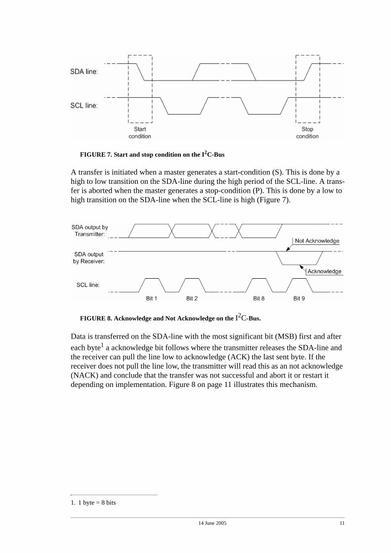
FIGURE 7. Start and stop condition on the I2C-Bus
A transfer is initiated when a master generates a start-condition (S). This is done by a high to low transition on the SDA-line during the high period of the SCL-line. A trans-fer is aborted when the master generates a stop-condition (P). This is done by a low to high transition on the SDA-line when the SCL-line is high (Figure 7).
FIGURE 8. Acknowledge and Not Acknowledge on the I2C-Bus.
Data is transferred on the SDA-line with the most significant bit (MSB) first and after each byte1 a acknowledge bit follows where the transmitter releases the SDA-line and the receiver can pull the line low to acknowledge (ACK) the last sent byte. If the receiver does not pull the line low, the transmitter will read this as an not acknowledge (NACK) and conclude that the transfer was not successful and abort it or restart it depending on implementation. Figure 8 on page 11 illustrates this mechanism.
1. 1 byte = 8 bits
14 June 2005 12
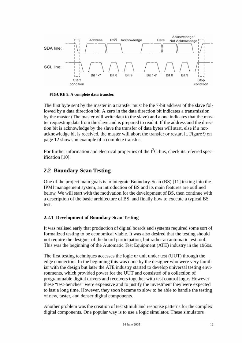
FIGURE 9. A complete data transfer.
The first byte sent by the master in a transfer must be the 7-bit address of the slave fol-lowed by a data direction bit. A zero in the data direction bit indicates a transmission by the master (The master will write data to the slave) and a one indicates that the mas-ter requesting data from the slave and is prepared to read it. If the address and the direc-tion bit is acknowledge by the slave the transfer of data bytes will start, else if a not-acknowledge bit is received, the master will abort the transfer or restart it. Figure 9 on page 12 shows an example of a complete transfer.
For further information and electrical properties of the I2C-bus, check its referred spec-ification [10].
2.2 Boundary-Scan Testing
One of the project main goals is to integrate Boundary-Scan (BS) [11] testing into the IPMI management system, an introduction of BS and its main features are outlined below. We will start with the motivation for the development of BS, then continue with a description of the basic architecture of BS, and finally how to execute a typical BS test.
2.2.1 Development of Boundary-Scan Testing
It was realised early that production of digital boards and systems required some sort of formalized testing to be economical viable. It was also desired that the testing should not require the designer of the board participation, but rather an automatic test tool. This was the beginning of the Automatic Test Equipment (ATE) industry in the 1960s.
The first testing techniques accesses the logic or unit under test (UUT) through the edge connectors. In the beginning this was done by the designer who were very famil-iar with the design but later the ATE industry started to develop universal testing envi-ronments, which provided power for the UUT and consisted of a collection of programmable digital drivers and receivers together with test control logic. However these “test-benches” were expensive and to justify the investment they were expected to last a long time. However, they soon became to slow to be able to handle the testing of new, faster, and denser digital components.
Another problem was the creation of test stimuli and response patterns for the complex digital components. One popular way is to use a logic simulator. These simulators
14 June 2005 13
allows the test engineer to build a model of the UUT and apply the test stimuli and inspect the responses. Simulator-based functional testing is still used today with new tools that have been able to keep up with the IC technology.
In the late 1970s In-Circuit testing (ICT) was developed. The idea was to not only be able to access external connectors, but also internal nodes in the logic. If these nodes could be observed and stimulated it would increase the possibility the detect faults in the design.
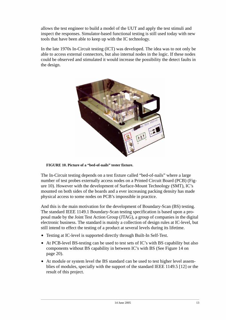
FIGURE 10. Picture of a “bed-of-nails” tester fixture.
The In-Circuit testing depends on a test fixture called “bed-of-nails” where a large number of test probes externally access nodes on a Printed Circuit Board (PCB) (Fig-ure 10). However with the development of Surface-Mount Technology (SMT), IC’s mounted on both sides of the boards and a ever increasing packing density has made physical access to some nodes on PCB’s impossible in practice.
And this is the main motivation for the development of Boundary-Scan (BS) testing. The standard IEEE 1149.1 Boundary-Scan testing specification is based upon a pro-posal made by the Joint Test Action Group (JTAG), a group of companies in the digital electronic business. The standard is mainly a collection of design rules at IC-level, but still intend to effect the testing of a product at several levels during its lifetime.
• Testing at IC-level is supported directly through Built-In Self-Test.
• At PCB-level BS-testing can be used to test sets of IC’s with BS capability but also components without BS capability in between IC’s with BS (See Figure 14 on page 20).
• At module or system level the BS standard can be used to test higher level assem-blies of modules, specially with the support of the standard IEEE 1149.5 [12] or the result of this project.
14 June 2005 14
Note that Boundary-Scan testing doesn’t replace In-Circuit testing, it just provides an easier way to access internal nodes, and in addition provides a protocol for this pur-pose.
2.2.2 Basic architecture
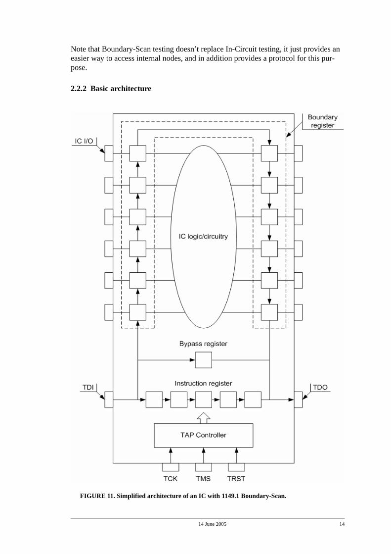
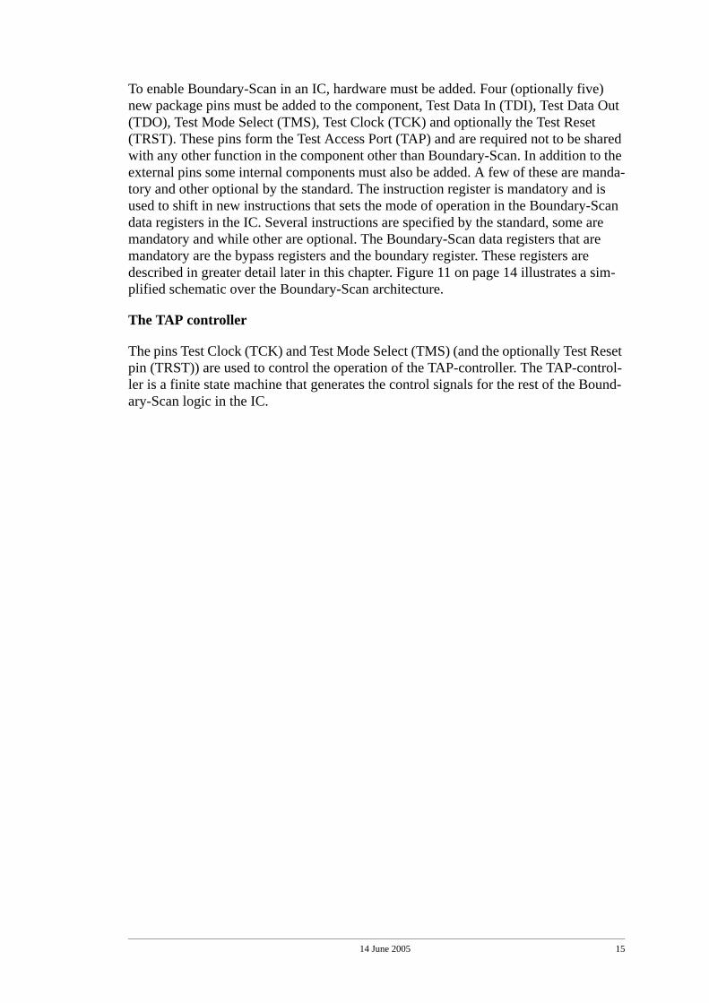
FIGURE 11. Simplified architecture of an IC with 1149.1 Boundary-Scan.
14 June 2005 15
To enable Boundary-Scan in an IC, hardware must be added. Four (optionally five) new package pins must be added to the component, Test Data In (TDI), Test Data Out (TDO), Test Mode Select (TMS), Test Clock (TCK) and optionally the Test Reset (TRST). These pins form the Test Access Port (TAP) and are required not to be shared with any other function in the component other than Boundary-Scan. In addition to the external pins some internal components must also be added. A few of these are manda-tory and other optional by the standard. The instruction register is mandatory and is used to shift in new instructions that sets the mode of operation in the Boundary-Scan data registers in the IC. Several instructions are specified by the standard, some are mandatory and while other are optional. The Boundary-Scan data registers that are mandatory are the bypass registers and the boundary register. These registers are described in greater detail later in this chapter. Figure 11 on page 14 illustrates a sim-plified schematic over the Boundary-Scan architecture.
The TAP controller
The pins Test Clock (TCK) and Test Mode Select (TMS) (and the optionally Test Reset pin (TRST)) are used to control the operation of the TAP-controller. The TAP-control-ler is a finite state machine that generates the control signals for the rest of the Bound-ary-Scan logic in the IC.
14 June 2005 16
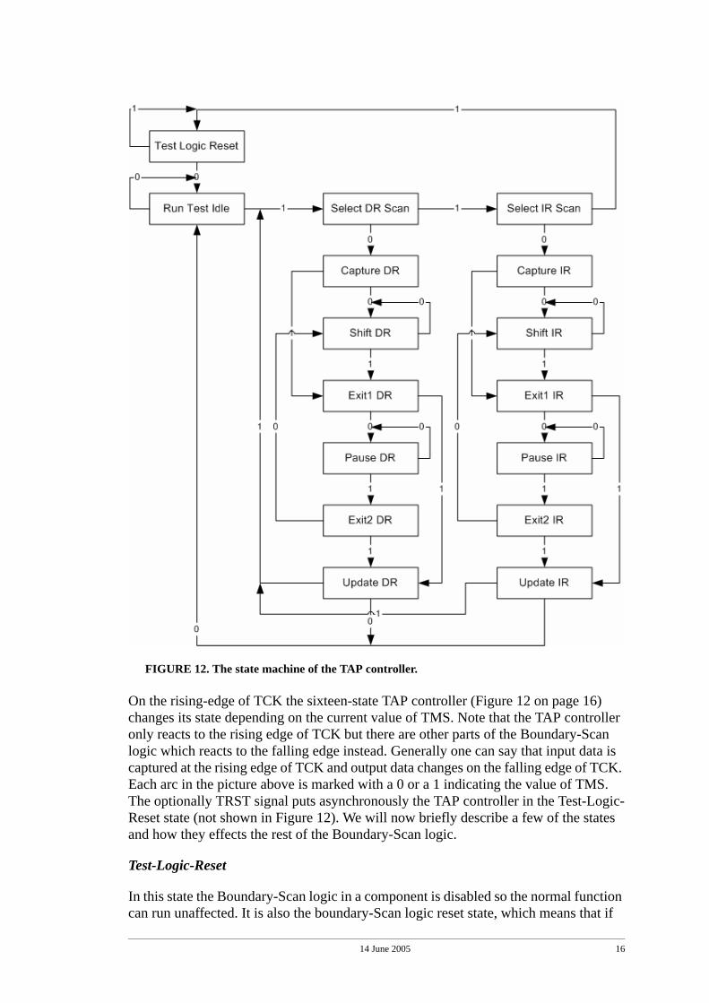
FIGURE 12. The state machine of the TAP controller.
On the rising-edge of TCK the sixteen-state TAP controller (Figure 12 on page 16) changes its state depending on the current value of TMS. Note that the TAP controller only reacts to the rising edge of TCK but there are other parts of the Boundary-Scan logic which reacts to the falling edge instead. Generally one can say that input data is captured at the rising edge of TCK and output data changes on the falling edge of TCK. Each arc in the picture above is marked with a 0 or a 1 indicating the value of TMS. The optionally TRST signal puts asynchronously the TAP controller in the Test-Logic-Reset state (not shown in Figure 12). We will now briefly describe a few of the states and how they effects the rest of the Boundary-Scan logic.
Test-Logic-Reset
In this state the Boundary-Scan logic in a component is disabled so the normal function can run unaffected. It is also the boundary-Scan logic reset state, which means that if
14 June 2005 17
TMS is held high (logic 1) for at least five rising edges of TCK this state will be entered or if the asynchronous TRST is asserted.
Run-Test-Idle
In this state all Boundary-Scan test logic is idle and retain their last state except when a user-defined or optionally instructions, like the RUNBIST instruction for example, are loaded. If such an instruction is loaded, the operation of the Boundary-Scan logic in Run-Test-Idle state is defined by it, and not by the specification.
Capture-DR/Capture-IR
In the Capture-DR state the data can be parallel-loaded into the shift-register part of the boundary-register in order to later be shifted out. In the instruction counterpart, Cap-ture-IR, the shift potion of the instruction-register is loaded with a fixed pattern where the two least significant bits are defined by the standard to “01”. This can be used for checking the integrity of the scan-chain.
Shift-DR/Shift-IR
In the Shift-DR state the shift part of the boundary-register is connected between TDI and TDO. If held in this state data will be shifted, on the rising edge of TCK, into the boundary-registers selected by the current instruction and the captured data present in the selected boundary registers will be shifted out. The Shift-IR state operates in the same way but on the instruction register. On the rising edge of TCK in this state new data (instructions) is shifted into the instruction register and the predefined captured data is shifted out.
Update-DR/Update-IR
On the falling edge of TCK and if the Update-DR state is the present the data previ-ously shifted into the selected data-registers will be latched out to its parallel outputs. The data held at the outputs changes only in this state. Similar in the Shift-IR state the previously in shifted instruction will be latched on the falling edge of TCK to the hold and decode potion of the instruction register and become the active instruction.
Pause-DR/Pause-IR
In these two state, the Pause-DR and Pause-IR states, the shifting process in the selected register between TDI and TDO is temporarily halted. This can be used, for example, to let a connected ATE system reload the tester memory with new vectors and read the vectors already shifted out.
The other TAP controller states not described above (Select-DR-Scan/Select-IR-Scan, Exit1-DR/Exit1-IR and Exit2-DR/Exit2-IR) are called “temporary controller states”, meaning that it will be exited on the next rising edge of TCK. They are used to split up the path where there is more than two ways to continue.
Beside the TAP controller, a few registers (Instruction register and the Data registers mentioned above.) are also defined. Some of these registers are mandatory but several other registers between TDI and TDO are allowed to be implemented and a few are
14 June 2005 18
described by the standard (optional), like the device identification register. However, we will here only describe the mandatory ones briefly.
The instruction register
The instruction register and its decode logic is controlled by the TAP-controller. When an instruction is shifted into the instruction register and loaded into its decode portion it sets the mode of operation for one or more of the data registers. The standard defines many instructions, a few are mandatory and others are optional. Its also allowed to define application (component) specific instructions as long as they does not interfere with the already specified ones.
The mandatory instructions are BYPASS, SAMPLE/PRELOAD and EXTEST. The BYPASS instruction places the single-bit Bypass shift register between TDI and TDO in a component. This to shorten the shift-path through components that are not under test.
The SAMPLE/PRELOAD instruction is basically two instructions that share the instruction code because they do not interfere with each others operation. The SAM-PLE part does not disconnect the system logic from the components pins, it just sam-ples the I/O-pins when the TAP controller is passing through the Capture-DR state and stores it in the selected Boundary registers. The PRELOAD part of the instruction is active when the TAP controller passes through the Update-DR state. When this hap-pens the previously in shifted data is stored in a parallel hold part of the boundary reg-ister. Note that its not interfering with the normal operation of the component, i.e. it is a non-invasive instruction.
The last mandatory instruction specified is the EXTEST instruction. This is the only mandatory instruction that is invasive and it is also the workhorse of Boundary-Scan testing. When the EXTEST instruction is loaded the outputs of the IC is controlled by the Boundary register (The previously in shifted data are driving the outputs.). Also, when the TAP controller passes through the Capture-DR state all the inputs of the com-ponent is stored their respective Boundary register cell. This data can then be shifted out during the Shift-DR state for examination. The EXTEST instruction thus enable us to stimulate outputs of a IC and on the other side, read the response input and shift it out for examination.
We will not describe the optional Boundary-Scan instruction in any detail. If the reader requires information about those, he is referred to the specification [11].
The Data registers
There are two mandatory data-registers defined in the specification, the bypass register and the boundary register. The bypass register is a mandatory register and consists of only one shift-cell. It is used when a IC is not required to participate in a test run and can be bypassed. This is used to shorten the Boundary-Scan chain significantly in a larger system. The bypass register is controller by the TAP-controller, and selected by the bypass-instruction.
The boundary register is mandatory in the standard and consists of boundary-scan cells adjacent to each input and output of an IC. It is used to assign and/or observe the values
14 June 2005 19
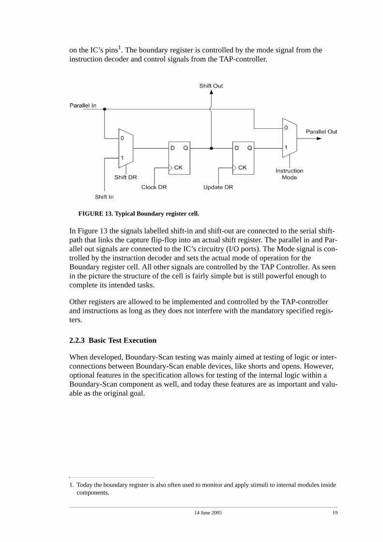
on the IC’s pins1. The boundary register is controlled by the mode signal from the instruction decoder and control signals from the TAP-controller.
FIGURE 13. Typical Boundary register cell.
In Figure 13 the signals labelled shift-in and shift-out are connected to the serial shift-path that links the capture flip-flop into an actual shift register. The parallel in and Par-allel out signals are connected to the IC’s circuitry (I/O ports). The Mode signal is con-trolled by the instruction decoder and sets the actual mode of operation for the Boundary register cell. All other signals are controlled by the TAP Controller. As seen in the picture the structure of the cell is fairly simple but is still powerful enough to complete its intended tasks.
Other registers are allowed to be implemented and controlled by the TAP-controller and instructions as long as they does not interfere with the mandatory specified regis-ters.
2.2.3 Basic Test Execution
When developed, Boundary-Scan testing was mainly aimed at testing of logic or inter-connections between Boundary-Scan enable devices, like shorts and opens. However, optional features in the specification allows for testing of the internal logic within a Boundary-Scan component as well, and today these features are as important and valu-able as the original goal.
1. Today the boundary register is also often used to monitor and apply stimuli to internal modules inside components.
14 June 2005 20
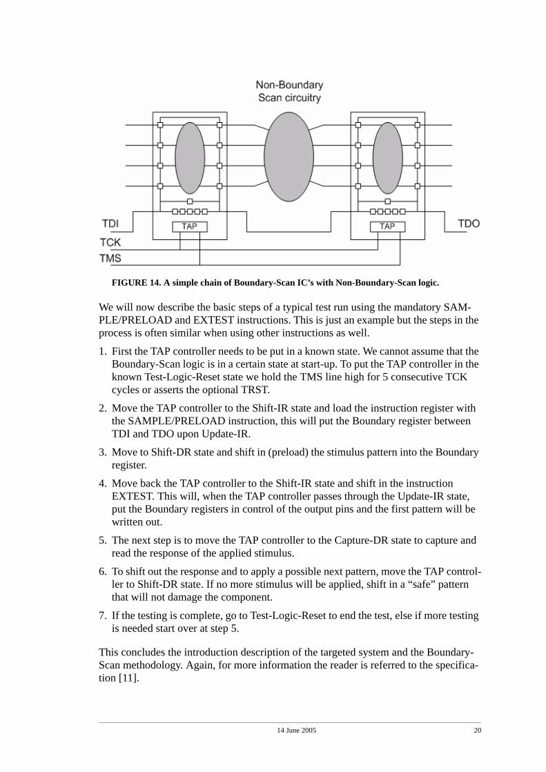
FIGURE 14. A simple chain of Boundary-Scan IC’s with Non-Boundary-Scan logic.
We will now describe the basic steps of a typical test run using the mandatory SAM-PLE/PRELOAD and EXTEST instructions. This is just an example but the steps in the process is often similar when using other instructions as well.
1. First the TAP controller needs to be put in a known state. We cannot assume that the Boundary-Scan logic is in a certain state at start-up. To put the TAP controller in the known Test-Logic-Reset state we hold the TMS line high for 5 consecutive TCK cycles or asserts the optional TRST.
2. Move the TAP controller to the Shift-IR state and load the instruction register with the SAMPLE/PRELOAD instruction, this will put the Boundary register between TDI and TDO upon Update-IR.
3. Move to Shift-DR state and shift in (preload) the stimulus pattern into the Boundary register.
4. Move back the TAP controller to the Shift-IR state and shift in the instruction EXTEST. This will, when the TAP controller passes through the Update-IR state, put the Boundary registers in control of the output pins and the first pattern will be written out.
5. The next step is to move the TAP controller to the Capture-DR state to capture and read the response of the applied stimulus.
6. To shift out the response and to apply a possible next pattern, move the TAP control-ler to Shift-DR state. If no more stimulus will be applied, shift in a “safe” pattern that will not damage the component.
7. If the testing is complete, go to Test-Logic-Reset to end the test, else if more testing is needed start over at step 5.
This concludes the introduction description of the targeted system and the Boundary-Scan methodology. Again, for more information the reader is referred to the specifica-tion [11].
14 June 2005 21
3.0 Problem Definition
In this section we will describe the problem, which the project is intended to solve, in detail. We will describe a few overall challenges together with three test scenarios and their related requirements on data and control transport. This will then be summarised into a list of goals in the end of the chapter.
3.1 Backplane and Linkage
Modern multi-board systems, like in the ATCA architecture described above, are usu-ally equipped with Boundary-Scan to ease testing. During operational and maintenance testing individual boards must be accessed through the backplane, and thus they require some sort of Boundary-Scan linkage. There are several commercial solutions available how to link a central controller to the local Boundary-Scan infrastructure using a Boundary-Scan bus in the backplane environment. However, all these solution requires additional dedicated wiring in the already crowded backplane.
Another problem is the possibility of data corruption during transportation in a back-plane environment. Direct linkage of a Boundary-Scan bus without any error detection/correction (See “Related work” on page 25.) is risky. This because fault control and test stimuli will not only make the test itself useless but in the worst case even damage the components under test.
3.2 Command set and Embedded data format
In addition to the above described challenges in the backplane environment there is also a need for a well defined mechanism to control and manage downloading, storing and execution of onboard test sets. Today, almost every vendor of automatic test equip-ment (ATE) has their own specific API/command set and data format to transport and store onboard embedded tests. The lack of a standardized command set is probably one of the most important reasons for the low deployment of embedded Boundary-Scan today. Also, this has led to unnecessary difficulties when designing system tests for multiboard systems where boards and components are made by several different ven-dors.
The suggested command set or API together with a well defined embedded test file for-mat should be able to provide the means to handle the following test scenarios. Note that these test scenarios are general in respect to what management system they rely on, however we want to implement them in a particular management system namely the IPMI.
3.2.1 Embedded pass/fail test
Typical usage is a test at cold (re)start of a board in the field due to a severe alarm, or as a regular test at non-busy hours. Short test time is often crucial. Control of the test may be through a system maintenance (operator) interface or through intelligent mainte-nance SW.
In Embedded pass/fail test, the test data is usually resident locally on the target board/module and only called to run by a simple command from the maintenance controller
14 June 2005 22
on the main control board. The analysis and comparison of the test response data is also done locally on the board. When completed, the board test controller responds with a small pass/fail message back to the maintenance controller on the main control board.
3.2.2 Embedded diagnostic test
Typical use is an extended test to detect potential HW faults that are not detected by the quick pass/fail test. The reason may be frequent alarms and restarts with suspected HW problems. A slightly longer test time may be allowed, if it results in a higher resolution of the test. Control of the test may be through a system maintenance (operator) inter-face.
Embedded diagnostic test is used to gain more information from a given set of stored test vectors/programs. As before, the comparison is made locally on the target board, but instead of only sending a small test report back to the controlling operator, the operator can select to retrieve a test log or even the actual test response data if needed.
3.2.3 Remote diagnostic test
Typical use is diagnostic test in a reference system in the repair shop. The test will be more capable to pinpoint faults to components and interfaces. Control of the test may be through a system maintenance (operator) interface or from a connected external test system.
Remote diagnostic test is used when extensive testing and flexibility are needed. Beside the resident tests on the target board, new test sets can also be downloaded and executed. The test responses are analysed at the target or sent back to an external test system for comparison and further study. In this scenario longer test times are accepted due to the higher rate of availability and flexibility.
3.3 Project Goals
This is a summarised list of goals derived from the described problems and challenges above.
• Reduce or remove the Boundary-Scan bus wiring in the backplane environment.
• Implement some sort of error detection/correction in the backplane Boundary-Scan data linkage.
• Provide a command set and embedded test data format to enable easy storing, man-agement and execution of embedded tests in a ATCA multiboard system.
• Provide means to handle the three test scenarios described above; pass/fail, embed-ded diagnostics and remote diagnostic tests.
• The new test functionality should fit in the ATCA/IPMI context.
3.4 System Backdoor
Another goal, and not really a problem is the possibility to use the IMPI as a system test backdoor. This due to the built in characteristic of IPMI (See “IPMI” on page 4.).
14 June 2005 23
This could enable system test access even when the rest of the system operation is lim-ited. During for example in a powered down state or when a fault has occurred that has taken the main backplane buses off-line. To be able to execute fault diagnostics in those conditions is a great feature, and perhaps one of the most important.

14 June 2005 24
14 June 2005 25
4.0 Related work
This section gives an overview of precious work that has targeted embedded Bound-ary-Scan in a multi-board environments. There are several solutions available how to link Boundary-Scan control from a central test controller to locally distributed test con-trollers. They could be divided into three groups;
• Boundary-Scan Architecture and Protocol. A standard Boundary-Scan bus is added and its protocol is used.
• Boundary-Scan Architecture and Extended Protocol. A standard Boundary-Scan bus is added but the protocol is extended with an addressing capability.
• Alternatives to Boundary-Scan. A completely different bus architecture is used to wrap and transport the Boundary-Scan data to the desired boards or modules.
We will now show a few examples of each group, and discuss their pros and cons.
4.1 Boundary-Scan Architecture and Protocol
The backplane is extended with Boundary-Scan and the standard Boundary-Scan pro-tocol is used. The two main variants of this approach are; the ring-architecture and the star-architecture. These are well-known but rarely used schemes in larger multi-board systems today. These examples do not require any additional implementation beside the standard Boundary-Scan requirements.
In the ring-architecture a complete Boundary-Scan chain is daisy-chained through the backplane and all the boards in the system. The approach creates a potentially long and cumbersome scan-chain to use. Such a solution in a multi-drop system also runs into problem when boards are removed or added to a shelf, since it requires some sort of physical jumpers/bridges when a card is removed or the chain will be broken.
The star-architecture is based directly on a pure Boundary-Scan bus. In the approach every board in the system uses a dedicated TMS line and the TAP controllers can then be controlled separately. However, such an approach requires large amount of connec-tion lines in the backplane (i.e. one additional line for each card).
The advantage of the ring and star architectures are that they do not require any addi-tional components or new protocols beside the required of the Boundary-Scan specifi-cation. This makes them simple to implement, but in a larger multi-board system often to cumbersome/impractical to use.
4.2 Boundary-Scan Architecture and Extended Protocol
The backplane is extended with Boundary-Scan wiring and the Boundary-Scan proto-col is extended. This approach is the one used mostly in today's systems. We will describe two of the most used designs, the Addressable Shadow Port by Texas Instru-ment (TI) and the SCAN Bridge by National Semiconductor (NSC).
Whetsel [4] presented a scheme where Addressable Shadow Ports (ASPs) are used to gain access to specific boards or scan-chains in a system. In this scheme a new protocol layer is added on the Boundary-Scan bus and used to link the backplane bus to the local
14 June 2005 26
scan-chain on the board before the actual testing commences. This new protocol is active when the Boundary-Scan logic is in its run-test/idle state, test-logic-reset state, pause-dr state or pause-ir state. It uses the then disabled TDI and TDO lines to facilitate a select/acknowledge protocol. Texas Instrument supplies interface components [14] that support this ASP scheme.
Another approach was first proposed by Bhavsar [2] and later developed further by National Semiconductor into the SCAN Bridge scheme [15]. In SCAN Bridge there is also an overhead protocol, but instead of using the Boundary-Scan bus in its idle states it shifts an address like an instruction using the shift-ir state on the TDI line. The addresses of the boards (i.e. the local scan-chains) are known to the interface units, and only the interface unit with the matching address is connected to the backplane bus (Level 1). The rest of the boards are disconnected. However before shifting in any test data to the target board can commence, a "Level 2"-protocol is used to further select among local scan-chains on the board.
Both the TI solution and the NSC solution rely on the standard 4-wire (optionally 5 wires) Boundary-Scan bus as a backplane interconnection (with their own specific modifications to the protocol). These additional wires, especially when an already implemented maintenance bus is available in ATCA, might be a deal-breaking require-ment.
In addition to the extra wiring in the backplane these solutions do not provide any detection of errors that may occur during backplane transmission. The result could expose the components-under-test to corrupted test and control data and in the worst case even damage the components. Ke et al. [3] proposed a novel scheme to include error detection into a standard Boundary-Scan backplane bus, such is used in the ASP and SCAN bridge designs. The extended IPMB protocol used in our solution does however already include error detection features.
4.3 Alternatives to Boundary-Scan
An alternative is to not make use of the Boundary-Scan bus at all, but instead make use of a totally different bus and protocol to transport test data in the backplane. The solu-tion presented in this paper falls into this group, because we use the IPMB bus and pro-tocol to transport and control the Boundary-Scan tests.
The IEEE standard 1149.5, the "Standard Module Test and Maintenance (MTM) Bus Protocol" [12] was designed to facilitate both testing and other maintenance functions in multi-board systems. The problem with the standard was that while it did specify the message transport interface on both sides, it did not specify an embedded test data for-mat or a command set to run specific tests. This was left open to the users of the stand-ard. It resulted in that the standard was never really adopted by the industry and is now abandoned.
Instead the Intelligent Platform Management Interface (IPMI) framework and the Intel-ligent Platform Management Bus (IPMB) bus was developed and is today increasingly gaining momentum through the ATCA system architecture. The IPMB bus is well suited for additional functions and only requires 2 wires in the backplane compared to
14 June 2005 27
MTM that requires 5 wires and ASP and Scan Bridge that require 4 each (standard Boundary-Scan Bus architecture).
Whetsel [4] also presented in his paper an expanded version of his proposed ASP scheme called Commendable ASP (CASP). Using CASP enables remote test access and data transfer operations. The CASP protocol also includes a cyclic redundancy check (CRC) for error detection that the original ASP protocol didn't include. He also suggests that CASP (or ASP) is possible to convey over a 2-wire serial bus instead of the 4-wire standard Boundary-Scan bus. The CASP scheme is however still bound to a particular bus protocol and architecture (2 or 4-wire) that's not available in today's sys-tem architectures like ATCA. Therefore it is essential to strive to make the command set and the data format as platform independent as possible by separating it from the design of the bus architecture.

14 June 2005 28
14 June 2005 29
5.0 Approach
In this chapter we will describe and motivate our suggested approach to solve the above stated problems and goals (See “Problem Definition” on page 21.). We will expand the usage of IPMI to include fault management, i.e. to let the IPMB carry Boundary-Scan test commands and data between the central SM unit and the locally distributed BMC units. This should be seen as a complement to the conventional way of having the main control processor controlling the testing of application boards, using the ordinary functional control path to the local board control processors. In this way, the IPMB could be regarded as a “system back door”, which allows testing even in case the ordinary control path is out of order. This way of using the IPMB is not vio-lating the IPMI/IPMB standards.We have divided the description of the solution into four sub chapters namely:
• A general description of where the Boundary-Scan functionality is implemented in the ATCA/IPMI architecture.
• A description of the extended IPMB protocol used to facilitate the transport of Boundary-Scan data and control.
• A specification of an API or a set of commands used by a human operator or an automated test program to manage the locally embedded tests and their execution.
• An embedded binary test vector format in which the locally onboard test sets will be stored in. This is the actual instructions that a low-level Boundary-Scan HW-driver in the BMC units will execute.
Note that this chapter only supplies an approach that solves the stated problem defini-tion. Implementation specific information are left out intentionally in this chapter and if implemented, can be found in the chapter describing the demonstrator (See “Demon-stration board” on page 41.).
5.1 The Added Boundary-Scan Functionality
This subsection describes the new modules that have been added to the IPMI manage-ment system and how they make use of the already available functions.
As mentioned before, IPMI is merely a framework to support implementation of new management functions. It provides, among other things, interfaces and bus structures (e.g. IPMB) to support a distributed management system. The framework, with some additions, is well suited for implementing embedded fault detection like the Boundary-Scan technique. The main IPMI controller on the shelf management board (i.e. the SM unit) will also be the main controller when performing Boundary-Scan applications. It receives commands from the system manager interface and according to those gives commands to the local management controllers (i.e. BMC’s) through its IPMB inter-face. Most of the low-level test sets will be stored on the local boards in the system, but new tests can also be downloaded to a local BMC through the operators interface. These additional test sets could be used when an extended embedded diagnostic or remote diagnostics is required on an application board (See “Remote diagnostic test” on page 22.). In some cases the SM unit could even be performing some trivial com-parison and analysis of the received test response. However, most of the time the SM
14 June 2005 30
unit will act like a bridge and command interpreter between the system management interface (operators interface) and IPMB link to the BMC units.
The local IPMI controllers on the boards are the units that perform the actual testing. In Figure 3 on page 6 there is a block called “Board specific function” in the BMC unit, it is here where the new Boundary-Scan Execution Control (BSEC) module will be implemented. The BSEC module receives command and data messages from IPMB and act accordingly. It is also this BSEC module that reads, interpret and executes the stored test programs (See “The Binary Vector Format” on page 39.) in the BMC unit. To ease the burden of the BMC implementation, especially when handling the serial interface of the Boundary-Scan bus, a special embedded Boundary-Scan controller can be used. These kind of controllers are basically just an asynchronous parallel to serial interface with a clock generator unit and has been commercially available for some time [16], [17].
5.2 The Extended IPMB Protocol
The IPMB standard protocol was originally designed to facilitate transport of small control and status messages in a distributed IPMI management system. However, when transport of Boundary-Scan data and control are needed the protocol is not enough ver-satile. To overcome this we designed protocol used “on top” of the standard IPMB pro-tocol, we can call this the extended IPMB protocol (eIPMB). This extended variant follows the requirements and rules of the standard IPMB protocol so the messages are still valid to transport on any IPMB according to the standard. To a standard BMC without an eIPMB interpreter, these new extended messages would seem no different than the standard IPMB messages.
The new extended structure is all located within the data potion of the IPMB message structure (Figure 5 on page 8). According to the IPMB specification the command field specifies the data potion of the message, therefore we also specified a new command set that is only used in the eIPMB. To avoid conflicts with already existing command sets in various network functions we also placed the new command set in the vendor specific OEM network functions range. One could argue that the Application network function should be used for this purpose and it would probably work fine. However, the latest IPMI specification recommends that new functionality should be placed in OEM network function since it predicts that future versions of the IPMI will place new com-mands under the application network function [7].
Note that the eIPMB command set is different from the one used by the operator or sys-tem management software to interface with the SM unit, this IPMB command set is only used to facilitate the messaging between the BSEC module in the BMC and the SM unit over the IPMB. However, they may have similarities but the separation is still important since it reflects different abstraction layers in the design. An operator con-trolling the tests through the system interface to the SM unit does not need any knowl-edge about the protocol used on the IPMB.
14 June 2005 31
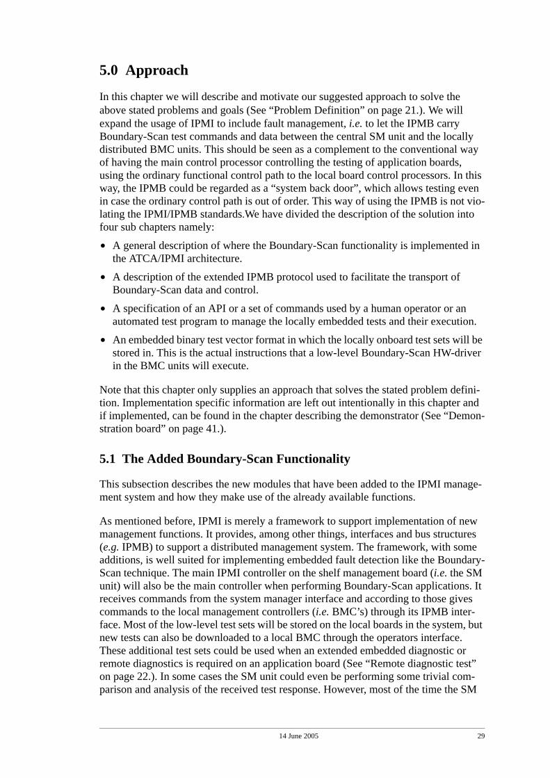
FIGURE 15. General IPMB message structure.
The tables that follows describes the command byte and the data section in the request messages and the command byte, completion code byte and the data section in the response messages of the eIPMB message structure. Some of the parameters listed below are implementation specific but still serves here to explain the overall structure of the messages. Figure 15 describes the general structure of the fields in an IPMB request and response.
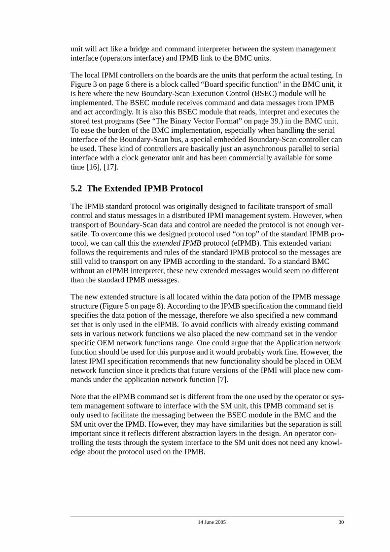
5.2.1 LIST message structure
The list messages are used when the SM unit requests a list of the stored test sets in the BMC. The BMC returns a response message for each SM request message containing information about a specific test set. Therefore, the number of sent responses and requests will be equal to the number of test stored in the BMC.
TABLE 1. LIST request, first message
Field Value DescriptionCommand 01h Used for all LIST requests and responses.Data[0] 01h Marks this message as the first in a complete LIST transaction.
TABLE 2. LIST response, first message
Field Value DescriptionCommand 01h Used for all LIST request and responses.Completion Code 00h Command completed normally.
D5h Cannot execute command. Command or request parameter(s) not supported in present statea. Another command or a “follow-ing LIST request” was expected.
CAh Cannot return number of requested data bytes. No test sets available for listing.

14 June 2005 32
The first messages, both request and response, differs slightly from the rest (the follow-ing) of the messages in a LIST transaction.
Data[0] 01h This response contains not the last entry in the complete list. More messages containing entries will follow.
02h This response contains the last entry in the complete list.Data[1] “num” One byte containing the number of the list entry (test number)
stored in ASCII format.Data[2 - 9] “name” 8 bytes containing the name of the test in ASCII format.Data[10 - 13] “rev.” 4 bytes containing the revision number of the test in ASCII.Data[14] 01h Kind of memory the test is stored in. Memory type = RAM.
02h Memory type = ROM.03h Memory type = VOL.
Data[15] 01h The result of the last test run. Result = PASSED.02h Result = FAILED.03h Result = UNKNOWN.
a. The term “present state” refers to that the software, in the SM unit and in the BMC units, is in a state where it expects certain messages to complete the transfer of a complete list for example.
TABLE 3. LIST request, following messages
Field Value DescriptionCommand 01h Used for all LIST requests and responses.Data[0] 02h Marks this message as a following message in a LIST transaction.
TABLE 4. LIST response, following messages
Field Value DescriptionCommand 01h Used for all LIST requests and responses.Completion Code 00h Command completed normally.
D5h Cannot execute command. Command or request parameter(s) not supported in present state. Another command or a “first LIST request” was expected.
Data[0] 01h This response contains not the last entry in the complete list. More messages containing entries will follow.
02h This response contains the last entry in the complete list.Data[1] “num” One byte containing the number of the list entry (test number)
stored in ASCII format.Data[2 - 9] “name” 8 bytes containing the name of the test in ASCII format.Data[10 - 13] “rev.” 4 bytes containing the revision number of the test in ASCII.Data[14] 01h Kind of memory the test is stored in. Memory type = RAM.
02h Memory type = ROM.03h Memory type = VOL.
Data[15] 01h The result of the last test run. Result = PASSED.
TABLE 2. LIST response, first message
Field Value Description
14 June 2005 33
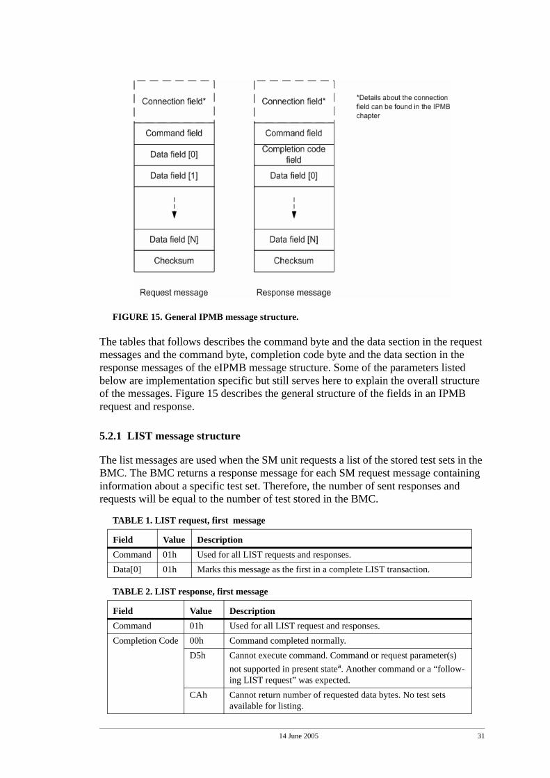
5.2.2 DELETE message structure
The delete messages are used when the SM unit requests that a certain stored test in the BMC unit should be removed. The response contains information if the removal of the test was successful or not. These messages are also used when deleting stored datalogs in the BMC unit1.
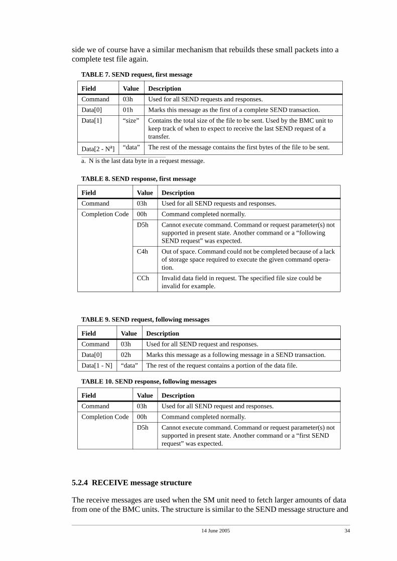
5.2.3 SEND message structure
The send messages are used when the SM unit requests to send a data file (e.g. a new test) to the BMC unit. The request contains the actual data of the file, and the responses are used to acknowledge the last sent request.
When sending larger test data files often several IPMB messages is needed for a com-plete transfer. A typical interconnection test file could be well over 50 kB in size and according to the IPMB standard, the maximum allowed packet size is 32 bytes. For this purpose we have constructed and implemented mechanisms for dividing larger test files into smaller packets that fit in the described message structure. On the receiver
02h Result = FAILED.03h Result = UNKNOWN.
TABLE 5. DELETE request, first and only message
Field Value DescriptionCommand 02h Used for all DELETE requests and responses.Data[0] 01h Tells the BMC unit that it is a test table entry that should be deleted.
02h Tells the BMC unit that it is a datalog entry that should be deleted.Data[1] “num” One byte containing the number of the entry to be deleted.
TABLE 6. DELETE response, first and only message
Field Value DescriptionCommand 02h Used for all DELETE requests and responses.Completion Code 00h Command completed normally.
D5h Cannot execute command. Command or request parameter(s) not supported in present state. Another command or a “following LIST request”/“following SEND request” was expected.
CCh Invalid data field in Request. The given test/data log (num) doesn’t exist.
FFh Unspecified error.
1. The datalog feature is not fully implemented in the demonstration board, so therefore these messages are only used when deleting tests.
TABLE 4. LIST response, following messages
Field Value Description
14 June 2005 34
side we of course have a similar mechanism that rebuilds these small packets into a complete test file again.
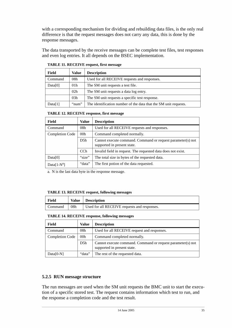
5.2.4 RECEIVE message structure
The receive messages are used when the SM unit need to fetch larger amounts of data from one of the BMC units. The structure is similar to the SEND message structure and
TABLE 7. SEND request, first message
Field Value DescriptionCommand 03h Used for all SEND requests and responses.Data[0] 01h Marks this message as the first of a complete SEND transaction.Data[1] “size” Contains the total size of the file to be sent. Used by the BMC unit to
keep track of when to expect to receive the last SEND request of a transfer.
Data[2 - Na]
a. N is the last data byte in a request message.
“data” The rest of the message contains the first bytes of the file to be sent.
TABLE 8. SEND response, first message
Field Value DescriptionCommand 03h Used for all SEND requests and responses.Completion Code 00h Command completed normally.
D5h Cannot execute command. Command or request parameter(s) not supported in present state. Another command or a “following SEND request” was expected.
C4h Out of space. Command could not be completed because of a lack of storage space required to execute the given command opera-tion.
CCh Invalid data field in request. The specified file size could be invalid for example.
TABLE 9. SEND request, following messages
Field Value DescriptionCommand 03h Used for all SEND request and responses.Data[0] 02h Marks this message as a following message in a SEND transaction.Data[1 - N] “data” The rest of the request contains a portion of the data file.
TABLE 10. SEND response, following messages
Field Value DescriptionCommand 03h Used for all SEND request and responses.Completion Code 00h Command completed normally.
D5h Cannot execute command. Command or request parameter(s) not supported in present state. Another command or a “first SEND request” was expected.
14 June 2005 35
with a corresponding mechanism for dividing and rebuilding data files, is the only real difference is that the request messages does not carry any data, this is done by the response messages.
The data transported by the receive messages can be complete test files, test responses and even log entries. It all depends on the BSEC implementation.
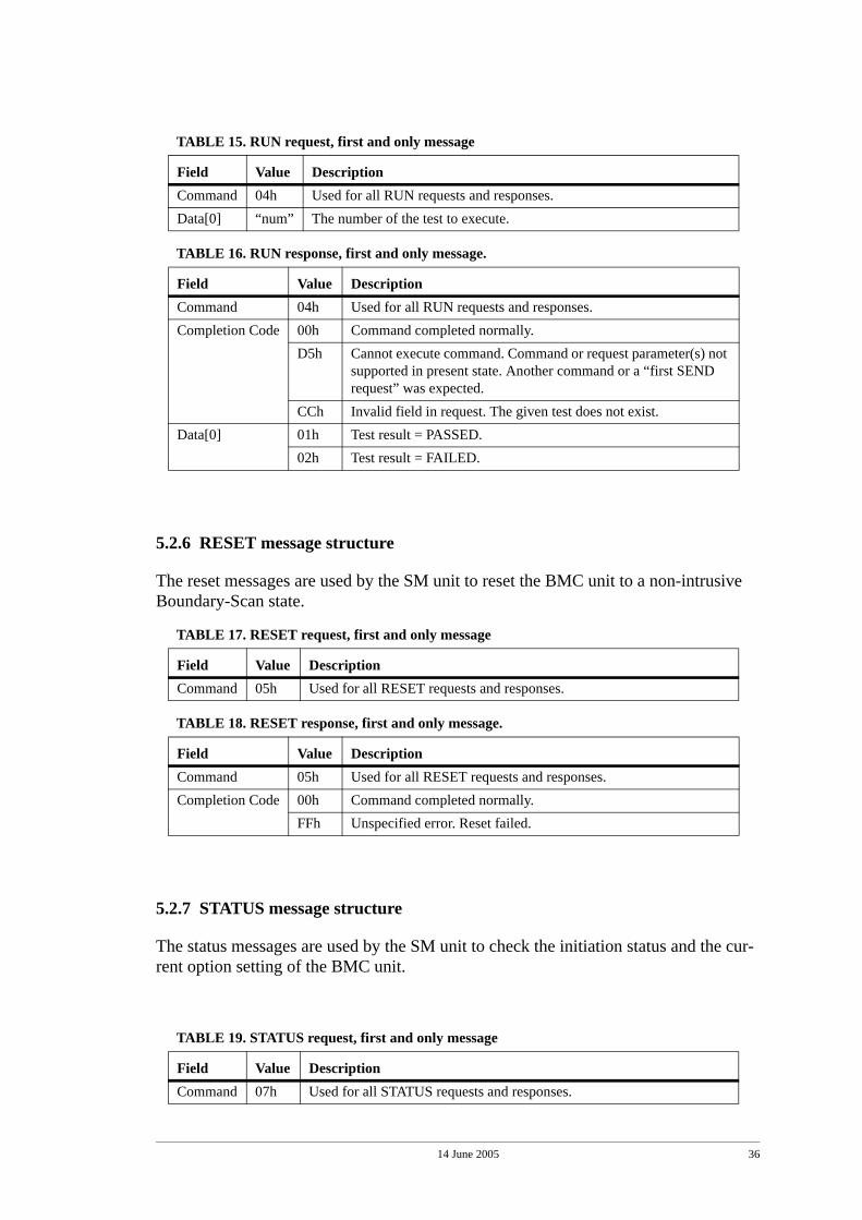
5.2.5 RUN message structure
The run messages are used when the SM unit requests the BMC unit to start the execu-tion of a specific stored test. The request contains information which test to run, and the response a completion code and the test result.
TABLE 11. RECEIVE request, first message
Field Value DescriptionCommand 08h Used for all RECEIVE requests and responses.Data[0] 01h The SM unit requests a test file.
02h The SM unit requests a data log entry.03h The SM unit requests a specific test response.
Data[1] “num” The identification number of the data that the SM unit requests.
TABLE 12. RECEIVE response, first message
Field Value DescriptionCommand 08h Used for all RECEIVE requests and responses.Completion Code 00h Command completed normally.
D5h Cannot execute command. Command or request parameter(s) not supported in present state.
CCh Invalid field in request. The requested data does not exist.Data[0] “size” The total size in bytes of the requested data.
Data[1-Na]
a. N is the last data byte in the response message.
“data” The first potion of the data requested.
TABLE 13. RECEIVE request, following messages
Field Value DescriptionCommand 08h Used for all RECEIVE requests and responses.
TABLE 14. RECEIVE response, following messages
Field Value DescriptionCommand 08h Used for all RECEIVE request and responses.Completion Code 00h Command completed normally.
D5h Cannot execute command. Command or request parameter(s) not supported in present state.
Data[0-N] “data” The rest of the requested data.
14 June 2005 36
5.2.6 RESET message structure
The reset messages are used by the SM unit to reset the BMC unit to a non-intrusive Boundary-Scan state.
5.2.7 STATUS message structure
The status messages are used by the SM unit to check the initiation status and the cur-rent option setting of the BMC unit.
TABLE 15. RUN request, first and only message
Field Value DescriptionCommand 04h Used for all RUN requests and responses.Data[0] “num” The number of the test to execute.
TABLE 16. RUN response, first and only message.
Field Value DescriptionCommand 04h Used for all RUN requests and responses.Completion Code 00h Command completed normally.
D5h Cannot execute command. Command or request parameter(s) not supported in present state. Another command or a “first SEND request” was expected.
CCh Invalid field in request. The given test does not exist.Data[0] 01h Test result = PASSED.
02h Test result = FAILED.
TABLE 17. RESET request, first and only message
Field Value DescriptionCommand 05h Used for all RESET requests and responses.
TABLE 18. RESET response, first and only message.
Field Value DescriptionCommand 05h Used for all RESET requests and responses.Completion Code 00h Command completed normally.
FFh Unspecified error. Reset failed.
TABLE 19. STATUS request, first and only message
Field Value DescriptionCommand 07h Used for all STATUS requests and responses.
14 June 2005 37
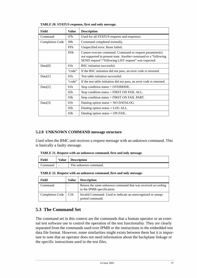
5.2.8 UNKNOWN COMMAND message structure
Used when the BMC unit receives a request message with an unknown command. This is basically a faulty message.
5.3 The Command Set
The command set in this context are the commands that a human operator or an exter-nal test software use to control the operation of the test functionality. They are clearly separated from the commands used over IPMB or the instructions in the embedded test data file format. However, some similarities might exists between them but it is impor-tant to note that an operator does not need information about the backplane linkage or the specific instructions used in the test files.
TABLE 20. STATUS response, first and only message.
Field Value DescriptionCommand 07h Used for all STATUS requests and responses.Completion Code 00h Command completed normally.
FFh Unspecified error. Reset failed.D5h Cannot execute command. Command or request parameter(s)
not supported in present state. Another command or a “following SEND request”/“following LIST request” was expected.
Data[0] 01h BSC initiation successful.“code” If the BSC initiation did not pass, an error code is returned.
Data[1] 01h Test table initiation successful.“code” If the test table initiation did not pass, an error code is returned.
Data[2] 01h Stop condition status = OVERRIDE.02h Stop condition status = FIRST ON FAIL ALL.03h Stop condition status = FIRST ON FAIL PART.
Data[3] 01h Datalog option status = NO DATALOG.02h Datalog option status = LOG ALL.03h Datalog option status = ON FAIL.
TABLE 21. Request with an unknown command, first and only message
Field Value DescriptionCommand - The unknown command.
TABLE 22. Request with an unknown command, first and only message.
Field Value DescriptionCommand - Return the same unknown command that was received according
to the IPMB specification.Completion Code C1h Invalid Command. Used to indicate an unrecognized or unsup-
ported command.
14 June 2005 38
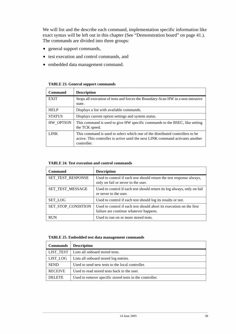
We will list and the describe each command, implementation specific information like exact syntax will be left out in this chapter (See “Demonstration board” on page 41.). The commands are divided into three groups:
• general support commands,
• test execution and control commands, and
• embedded data management command.
TABLE 23. General support commands
Command DescriptionEXIT Stops all execution of tests and forces the Boundary-Scan HW in a non-intrusive
state.HELP Displays a list with available commands.STATUS Displays current option settings and system status.HW_OPTION This command is used to give HW specific commands to the BSEC, like setting
the TCK speed.LINK This command is used to select which one of the distributed controllers to be
active. This controller is active until the next LINK command activates another controller.
TABLE 24. Test execution and control commands
Command DescriptionSET_TEST_RESPONSE Used to control if each test should return the test response always,
only on fail or never to the user.SET_TEST_MESSAGE Used to control if each test should return its log always, only on fail
or never to the user.SET_LOG Used to control if each test should log its results or not.SET_STOP_CONDITION Used to control if each test should abort its execution on the first
failure are continue whatever happens.RUN Used to run on or more stored tests.
TABLE 25. Embedded test data management commands
Commands DescriptionLIST_TEST Lists all onboard stored tests.LIST_LOG Lists all onboard stored log entries.SEND Used to send new tests to the local controller.RECEIVE Used to read stored tests back to the user.DELETE Used to remove specific stored tests in the controller.
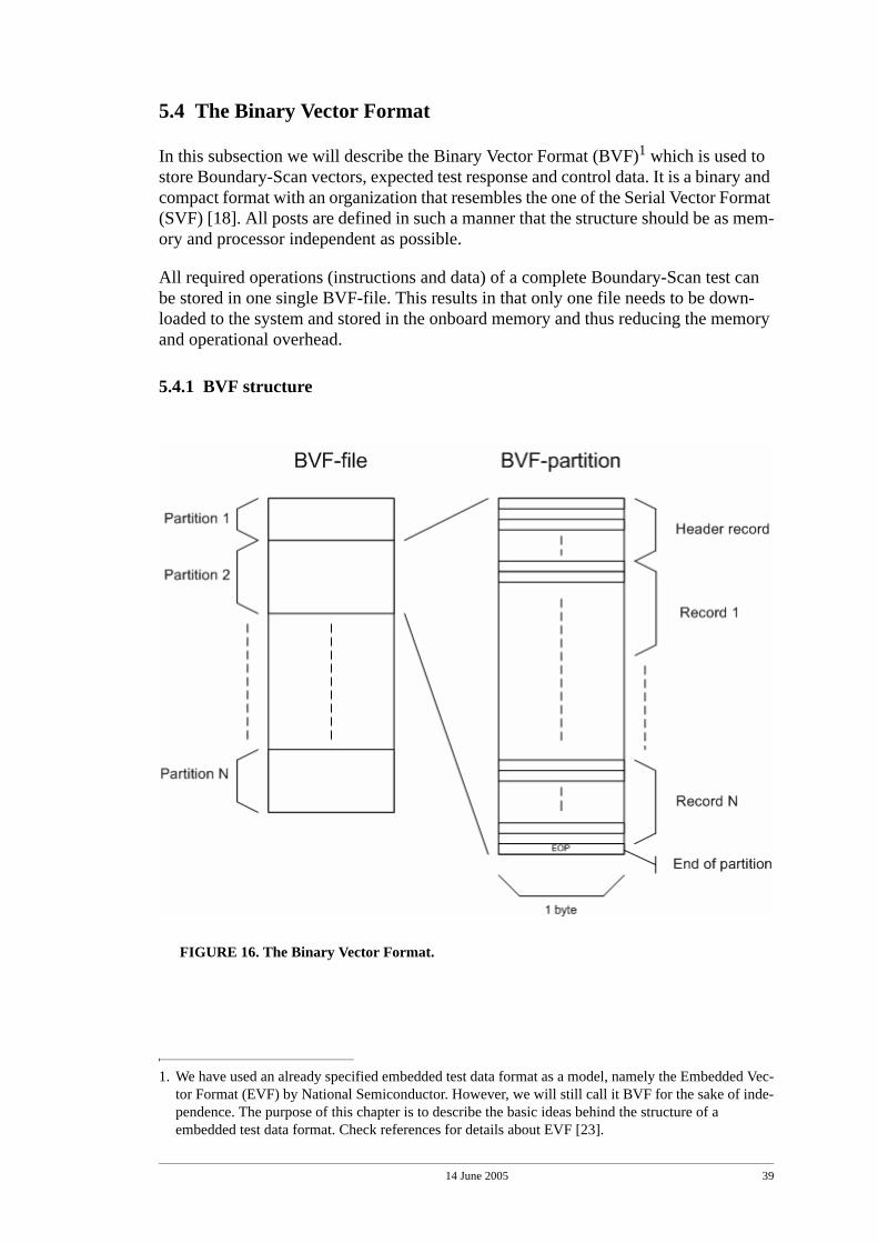
14 June 2005 39
5.4 The Binary Vector Format
In this subsection we will describe the Binary Vector Format (BVF)1 which is used to store Boundary-Scan vectors, expected test response and control data. It is a binary and compact format with an organization that resembles the one of the Serial Vector Format (SVF) [18]. All posts are defined in such a manner that the structure should be as mem-ory and processor independent as possible.
All required operations (instructions and data) of a complete Boundary-Scan test can be stored in one single BVF-file. This results in that only one file needs to be down-loaded to the system and stored in the onboard memory and thus reducing the memory and operational overhead.
5.4.1 BVF structure
FIGURE 16. The Binary Vector Format.
1. We have used an already specified embedded test data format as a model, namely the Embedded Vec-tor Format (EVF) by National Semiconductor. However, we will still call it BVF for the sake of inde-pendence. The purpose of this chapter is to describe the basic ideas behind the structure of a embedded test data format. Check references for details about EVF [23].
14 June 2005 40
Every BVF-file is composed of a number of BVF partitions, and every BVF partition is composed of a number of BVF records. Every BVF partition begins with a header record and ends with an End Of Partition record (i.e. EOP) (Figure 16).
The header record contains information about its BVF partition like the total size of the partition and the buffer memory requirements to run it. It also holds identification information about the test like the name, date, and revision number. The EOP record is just a single byte to mark the end of the partition.
The operational records between the header record and the end of partition record can be seen as the actual instructions that the BSEC module in the BMC unit executes on the Boundary-Scan bus. The header record, the operational records, and last to the EOP record are together forming the a complete test. We will now shortly describe a few of the main characteristics of some of the most important operational records used in the BVF.
The Scan Records
The Scan Data Record (SDR) and the Scan Instruction Record (SIR) are used to instruct the BSEC module to perform a Boundary register scan or a Instruction register scan on the Boundary-Scan bus (See “Basic architecture” on page 14.). These records are used to apply new test stimuli or load new instructions to the Boundary-Scan logic of the UUT. They can also instruct the BSEC module to read the out-shifted data from Boundary-Scan bus and compare it to an expected response.
The Run Test Record
The Run Test Record (RUN) is used to start and hold the Boundary-Scan logic in the Run-Test/Idle state for a specified number of cycles. This is used for example to run a BIST in the UUT.
The Test Reset Record
The Test Reset Record (TRST) is used to instruct the BSEC to seize all test execution and force the Boundary-Scan logic into a non-intrusive state.
The versatility of this structure enables us to design any kind of test we need, from small onboard BIST performed at start-up to complex interconnection tests executed at a repair shop. Therefore, together with the specified command set, we conclude that our solution provides the means to fulfil the requirements of the three earlier presented test scenarios (See “Command set and Embedded data format” on page 21.).
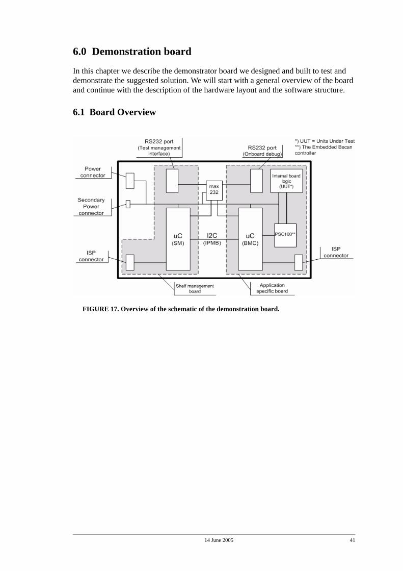
14 June 2005 41
6.0 Demonstration board
In this chapter we describe the demonstrator board we designed and built to test and demonstrate the suggested solution. We will start with a general overview of the board and continue with the description of the hardware layout and the software structure.
6.1 Board Overview
FIGURE 17. Overview of the schematic of the demonstration board.
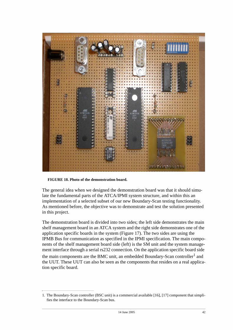
14 June 2005 42
FIGURE 18. Photo of the demonstration board.
The general idea when we designed the demonstration board was that it should simu-late the fundamental parts of the ATCA/IPMI system structure, and within this an implementation of a selected subset of our new Boundary-Scan testing functionality. As mentioned before, the objective was to demonstrate and test the solution presented in this project.
The demonstration board is divided into two sides; the left side demonstrates the main shelf management board in an ATCA system and the right side demonstrates one of the application specific boards in the system (Figure 17). The two sides are using the IPMB Bus for communication as specified in the IPMI specification. The main compo-nents of the shelf management board side (left) is the SM unit and the system manage-ment interface through a serial rs232 connection. On the application specific board side the main components are the BMC unit, an embedded Boundary-Scan controller1 and the UUT. These UUT can also be seen as the components that resides on a real applica-tion specific board.
1. The Boundary-Scan controller (BSC unit) is a commercial available [16], [17] component that simpli-fies the interface to the Boundary-Scan bus.
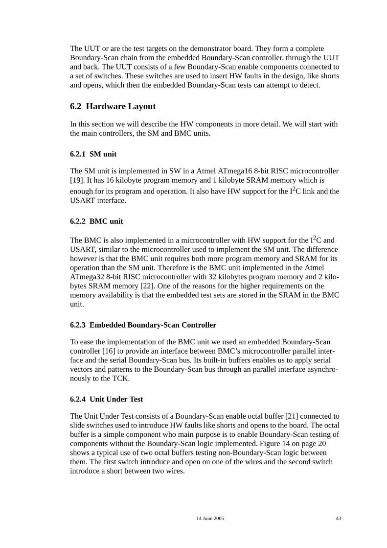
14 June 2005 43
The UUT or are the test targets on the demonstrator board. They form a complete Boundary-Scan chain from the embedded Boundary-Scan controller, through the UUT and back. The UUT consists of a few Boundary-Scan enable components connected to a set of switches. These switches are used to insert HW faults in the design, like shorts and opens, which then the embedded Boundary-Scan tests can attempt to detect.
6.2 Hardware Layout
In this section we will describe the HW components in more detail. We will start with the main controllers, the SM and BMC units.
6.2.1 SM unit
The SM unit is implemented in SW in a Atmel ATmega16 8-bit RISC microcontroller [19]. It has 16 kilobyte program memory and 1 kilobyte SRAM memory which is enough for its program and operation. It also have HW support for the I2C link and the USART interface.
6.2.2 BMC unit
The BMC is also implemented in a microcontroller with HW support for the I2C and USART, similar to the microcontroller used to implement the SM unit. The difference however is that the BMC unit requires both more program memory and SRAM for its operation than the SM unit. Therefore is the BMC unit implemented in the Atmel ATmega32 8-bit RISC microcontroller with 32 kilobytes program memory and 2 kilo-bytes SRAM memory [22]. One of the reasons for the higher requirements on the memory availability is that the embedded test sets are stored in the SRAM in the BMC unit.
6.2.3 Embedded Boundary-Scan Controller
To ease the implementation of the BMC unit we used an embedded Boundary-Scan controller [16] to provide an interface between BMC’s microcontroller parallel inter-face and the serial Boundary-Scan bus. Its built-in buffers enables us to apply serial vectors and patterns to the Boundary-Scan bus through an parallel interface asynchro-nously to the TCK.
6.2.4 Unit Under Test
The Unit Under Test consists of a Boundary-Scan enable octal buffer [21] connected to slide switches used to introduce HW faults like shorts and opens to the board. The octal buffer is a simple component who main purpose is to enable Boundary-Scan testing of components without the Boundary-Scan logic implemented. Figure 14 on page 20 shows a typical use of two octal buffers testing non-Boundary-Scan logic between them. The first switch introduce and open on one of the wires and the second switch introduce a short between two wires.
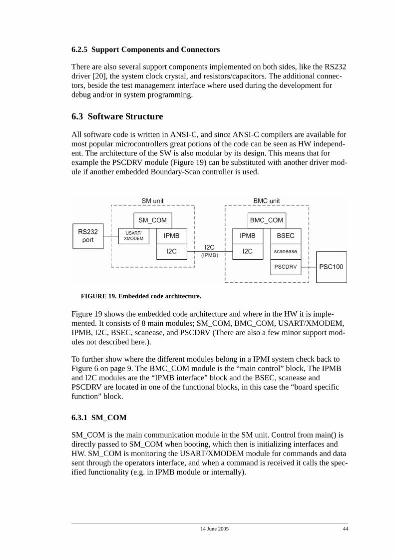
14 June 2005 44
6.2.5 Support Components and Connectors
There are also several support components implemented on both sides, like the RS232 driver [20], the system clock crystal, and resistors/capacitors. The additional connec-tors, beside the test management interface where used during the development for debug and/or in system programming.
6.3 Software Structure
All software code is written in ANSI-C, and since ANSI-C compilers are available for most popular microcontrollers great potions of the code can be seen as HW independ-ent. The architecture of the SW is also modular by its design. This means that for example the PSCDRV module (Figure 19) can be substituted with another driver mod-ule if another embedded Boundary-Scan controller is used.
FIGURE 19. Embedded code architecture.
Figure 19 shows the embedded code architecture and where in the HW it is imple-mented. It consists of 8 main modules; SM_COM, BMC_COM, USART/XMODEM, IPMB, I2C, BSEC, scanease, and PSCDRV (There are also a few minor support mod-ules not described here.).
To further show where the different modules belong in a IPMI system check back to Figure 6 on page 9. The BMC_COM module is the “main control” block, The IPMB and I2C modules are the “IPMB interface” block and the BSEC, scanease and PSCDRV are located in one of the functional blocks, in this case the “board specific function” block.
6.3.1 SM_COM
SM_COM is the main communication module in the SM unit. Control from main() is directly passed to SM_COM when booting, which then is initializing interfaces and HW. SM_COM is monitoring the USART/XMODEM module for commands and data sent through the operators interface, and when a command is received it calls the spec-ified functionality (e.g. in IPMB module or internally).
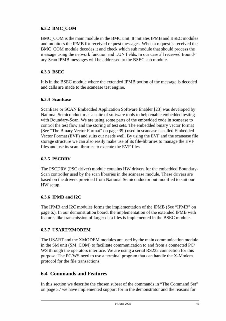
14 June 2005 45
6.3.2 BMC_COM
BMC_COM is the main module in the BMC unit. It initiates IPMB and BSEC modules and monitors the IPMB for received request messages. When a request is received the BMC_COM module decodes it and check which sub module that should process the message using the network function and LUN fields. In our case all received Bound-ary-Scan IPMB messages will be addressed to the BSEC sub module.
6.3.3 BSEC
It is in the BSEC module where the extended IPMB potion of the message is decoded and calls are made to the scanease test engine.
6.3.4 ScanEase
ScanEase or SCAN Embedded Application Software Enabler [23] was developed by National Semiconductor as a suite of software tools to help enable embedded testing with Boundary-Scan. We are using some parts of the embedded code in scanease to control the test flow and the storing of test sets. The embedded binary vector format (See “The Binary Vector Format” on page 39.) used in scanease is called Embedded Vector Format (EVF) and suits our needs well. By using the EVF and the scanease file storage structure we can also easily make use of its file-libraries to manage the EVF files and use its scan libraries to execute the EVF files.
6.3.5 PSCDRV
The PSCDRV (PSC driver) module contains HW drivers for the embedded Boundary-Scan controller used by the scan libraries in the scanease module. These drivers are based on the drivers provided from National Semiconductor but modified to suit our HW setup.
6.3.6 IPMB and I2C
The IPMB and I2C modules forms the implementation of the IPMB (See “IPMB” on page 6.). In our demonstration board, the implementation of the extended IPMB with features like transmission of larger data files is implemented in the BSEC module.
6.3.7 USART/XMODEM
The USART and the XMODEM modules are used by the main communication module in the SM unit (SM_COM) to facilitate communication to and from a connected PC/WS through the operators interface. We are using a serial RS232 connection for this purpose. The PC/WS need to use a terminal program that can handle the X-Modem protocol for the file transactions.
6.4 Commands and Features
In this section we describe the chosen subset of the commands in “The Command Set” on page 37 we have implemented support for in the demonstrator and the reasons for
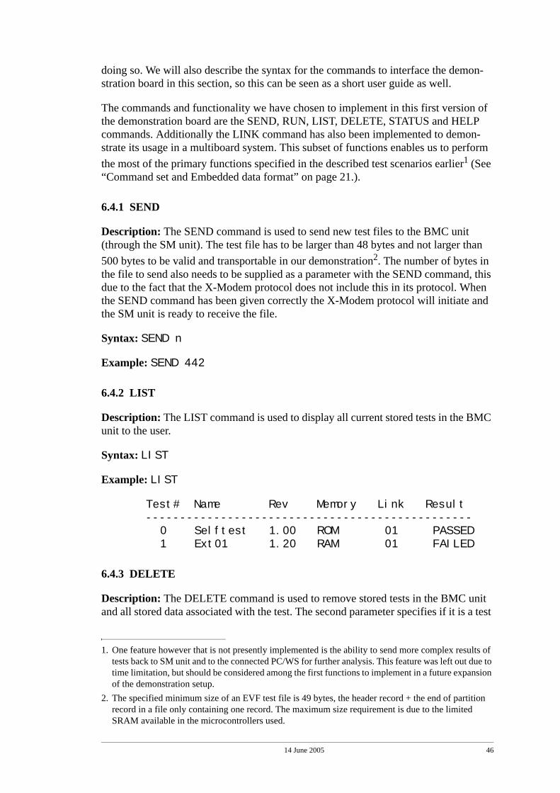
14 June 2005 46
doing so. We will also describe the syntax for the commands to interface the demon-stration board in this section, so this can be seen as a short user guide as well.
The commands and functionality we have chosen to implement in this first version of the demonstration board are the SEND, RUN, LIST, DELETE, STATUS and HELP commands. Additionally the LINK command has also been implemented to demon-strate its usage in a multiboard system. This subset of functions enables us to perform the most of the primary functions specified in the described test scenarios earlier1 (See “Command set and Embedded data format” on page 21.).
6.4.1 SEND
Description: The SEND command is used to send new test files to the BMC unit (through the SM unit). The test file has to be larger than 48 bytes and not larger than 500 bytes to be valid and transportable in our demonstration2. The number of bytes in the file to send also needs to be supplied as a parameter with the SEND command, this due to the fact that the X-Modem protocol does not include this in its protocol. When the SEND command has been given correctly the X-Modem protocol will initiate and the SM unit is ready to receive the file.
Syntax: SEND n
Example: SEND 442
6.4.2 LIST
Description: The LIST command is used to display all current stored tests in the BMC unit to the user.
Syntax: LIST
Example: LIST
Test# Name Rev Memory Link Result------------------------------------------------ 0 Selftest 1.00 ROM 01 PASSED 1 Ext01 1.20 RAM 01 FAILED
6.4.3 DELETE
Description: The DELETE command is used to remove stored tests in the BMC unit and all stored data associated with the test. The second parameter specifies if it is a test
1. One feature however that is not presently implemented is the ability to send more complex results of tests back to SM unit and to the connected PC/WS for further analysis. This feature was left out due to time limitation, but should be considered among the first functions to implement in a future expansion of the demonstration setup.
2. The specified minimum size of an EVF test file is 49 bytes, the header record + the end of partition record in a file only containing one record. The maximum size requirement is due to the limited SRAM available in the microcontrollers used.
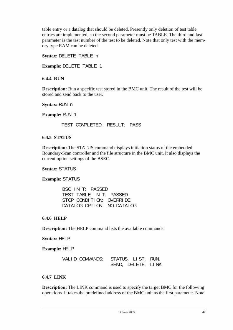
14 June 2005 47
table entry or a datalog that should be deleted. Presently only deletion of test table entries are implemented, so the second parameter must be TABLE. The third and last parameter is the test number of the test to be deleted. Note that only test with the mem-ory type RAM can be deleted.
Syntax: DELETE TABLE n
Example: DELETE TABLE 1
6.4.4 RUN
Description: Run a specific test stored in the BMC unit. The result of the test will be stored and send back to the user.
Syntax: RUN n
Example: RUN 1
TEST COMPLETED, RESULT: PASS
6.4.5 STATUS
Description: The STATUS command displays initiation status of the embedded Boundary-Scan controller and the file structure in the BMC unit. It also displays the current option settings of the BSEC.
Syntax: STATUS
Example: STATUS
BSC INIT: PASSEDTEST TABLE INIT: PASSEDSTOP CONDITION: OVERRIDEDATALOG OPTION: NO DATALOG
6.4.6 HELP
Description: The HELP command lists the available commands.
Syntax: HELP
Example: HELP
VALID COMMANDS: STATUS, LIST, RUN, SEND, DELETE, LINK
6.4.7 LINK
Description: The LINK command is used to specify the target BMC for the following operations. It takes the predefined address of the BMC unit as the first parameter. Note

14 June 2005 48
that this command has to be used before any of the other commands can be used (Except the HELP command.).
Syntax: LINK n
Example: LINK 16
14 June 2005 49
7.0 Experimental Results
In this chapter we discuss the issues about the actual performance of our presented solution.
7.1 IPMB Performance
While there are many advantages by transporting Boundary-Scan data over the IPMB there are also drawbacks. First of all, sending large amount of data on a serial wire is time consuming, especially compared to a parallel bus. Secondly, compared to the other mentioned solutions how to link Boundary-Scan in the backplane (See “Related work” on page 25.) the Boundary-Scan data has to share the IPMB bandwidth with other IPMI functions, while the other solutions have a whole bus dedicated to Bound-ary-Scan.
Since IPMB is a bus used by several controllers with various functions in IPMI, restric-tions and recommendation has been placed on the messaging so that availability of the bus is shared among its nodes. These restrictions and recommendations works fine when the bus is used for short status and control messages, but when larger amounts of test data is transported they could have a great impact on the performance. The two main restrictions on the IPMB are:
• The standard data rate of the I2C-Bus which is 100 kbit/s. Faster modes with 400 kbits/s and 3.4 Mbits/s are available in the I2C specification, but it is today not allowed by the IPMB.
• The maximum IPMB message/packet size of 32 bytes. There is also a restriction on the overall message duration allowed on the IPMB, which is 20 ms. However, the 32 bytes packet size restriction is a much stricter rule than the 20 ms message dura-tion time.
7.2 Transport time computation
In this section we will show the equations used to calculate the time consumed (and thus the performance) when transporting data on the IPMB using our extended proto-col. Then we will use data from real test operations on an example system and receive the required transport time. We will also lift one or both of the two above mentioned restrictions to show a possible performance gain.
The transfers of interest is when we want to send larger EVF test files to the BMC unit from the SM unit using the IPMB. The command that handles this is the SEND com-mand. The rest of the commands results in single or a few (less then ten) packets on the IPMB. A transfer of data from the BMC unit to the SM unit would be very similar to a transfer from the SM unit to the BMC unit, so the calculations and examples here does apply to transfers in both directions.
We need first to make a few assumptions about the IPMB environment:
• The load on the IPMB, beside our Boundary-Scan data, is assumed to be negligible in comparison. The normal operational messages of IPMI is typical small and infre-quent and just adds a static overhead to the total time calculations. Therefore we
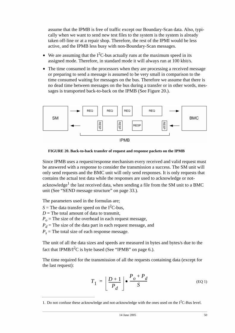
14 June 2005 50
assume that the IPMB is free of traffic except our Boundary-Scan data. Also, typi-cally when we want to send new test files to the system is the system is already taken off-line or at a repair shop. Therefore, the rest of the IPMI would be less active, and the IPMB less busy with non-Boundary-Scan messages.
• We are assuming that the I2C-bus actually runs at the maximum speed in its assigned mode. Therefore, in standard mode it will always run at 100 kbit/s.
• The time consumed in the processors when they are processing a received message or preparing to send a message is assumed to be very small in comparison to the time consumed waiting for messages on the bus. Therefore we assume that there is no dead time between messages on the bus during a transfer or in other words, mes-sages is transported back-to-back on the IPMB (See Figure 20.).
FIGURE 20. Back-to-back transfer of request and response packets on the IPMB
Since IPMB uses a request/response mechanism every received and valid request must be answered with a response to consider the transmission a success. The SM unit will only send requests and the BMC unit will only send responses. It is only requests that contains the actual test data while the responses are used to acknowledge or not-acknowledge1 the last received data, when sending a file from the SM unit to a BMC unit (See “SEND message structure” on page 33.).
The parameters used in the formulas are; S = The data transfer speed on the I2C-bus,D = The total amount of data to transmit,Po = The size of the overhead in each request message,Pd = The size of the data part in each request message, andPs = The total size of each response message.
The unit of all the data sizes and speeds are measured in bytes and bytes/s due to the fact that IPMB/I2C is byte based (See “IPMB” on page 6.).
The time required for the transmission of all the requests containing data (except for the last request):
(EQ 1)
1. Do not confuse these acknowledge and not-acknowledge with the ones used on the I2C-Bus level.
T1D 1+
Pd-------------
Po Pd+S
-------------------•=
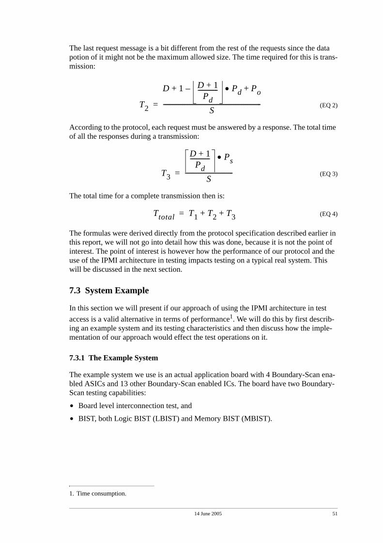
14 June 2005 51
The last request message is a bit different from the rest of the requests since the data potion of it might not be the maximum allowed size. The time required for this is trans-mission:
(EQ 2)
According to the protocol, each request must be answered by a response. The total time of all the responses during a transmission:
(EQ 3)
The total time for a complete transmission then is:
(EQ 4)
The formulas were derived directly from the protocol specification described earlier in this report, we will not go into detail how this was done, because it is not the point of interest. The point of interest is however how the performance of our protocol and the use of the IPMI architecture in testing impacts testing on a typical real system. This will be discussed in the next section.
7.3 System Example
In this section we will present if our approach of using the IPMI architecture in test access is a valid alternative in terms of performance1. We will do this by first describ-ing an example system and its testing characteristics and then discuss how the imple-mentation of our approach would effect the test operations on it.
7.3.1 The Example System
The example system we use is an actual application board with 4 Boundary-Scan ena-bled ASICs and 13 other Boundary-Scan enabled ICs. The board have two Boundary-Scan testing capabilities:
• Board level interconnection test, and
• BIST, both Logic BIST (LBIST) and Memory BIST (MBIST).
1. Time consumption.
T2
D 1 D 1+Pd
------------- Pd Po+•–+
S-----------------------------------------------------------------=
T3
D 1+Pd
------------- Ps•
S--------------------------------=
Ttotal T1 T2 T3+ +=
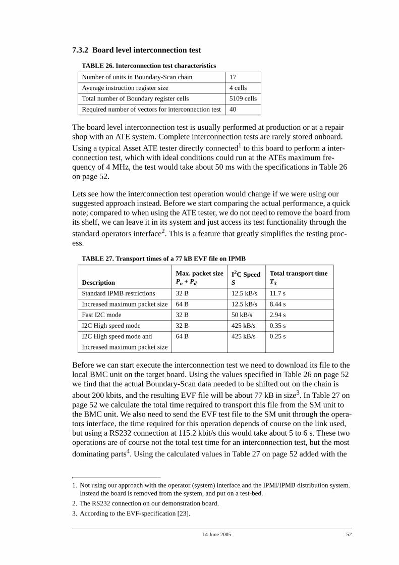
14 June 2005 52
7.3.2 Board level interconnection test
The board level interconnection test is usually performed at production or at a repair shop with an ATE system. Complete interconnection tests are rarely stored onboard. Using a typical Asset ATE tester directly connected1 to this board to perform a inter-connection test, which with ideal conditions could run at the ATEs maximum fre-quency of 4 MHz, the test would take about 50 ms with the specifications in Table 26 on page 52.
Lets see how the interconnection test operation would change if we were using our suggested approach instead. Before we start comparing the actual performance, a quick note; compared to when using the ATE tester, we do not need to remove the board from its shelf, we can leave it in its system and just access its test functionality through the standard operators interface2. This is a feature that greatly simplifies the testing proc-ess.
Before we can start execute the interconnection test we need to download its file to the local BMC unit on the target board. Using the values specified in Table 26 on page 52 we find that the actual Boundary-Scan data needed to be shifted out on the chain is about 200 kbits, and the resulting EVF file will be about 77 kB in size3. In Table 27 on page 52 we calculate the total time required to transport this file from the SM unit to the BMC unit. We also need to send the EVF test file to the SM unit through the opera-tors interface, the time required for this operation depends of course on the link used, but using a RS232 connection at 115.2 kbit/s this would take about 5 to 6 s. These two operations are of course not the total test time for an interconnection test, but the most dominating parts4. Using the calculated values in Table 27 on page 52 added with the
TABLE 26. Interconnection test characteristics
Number of units in Boundary-Scan chain 17Average instruction register size 4 cellsTotal number of Boundary register cells 5109 cellsRequired number of vectors for interconnection test 40
1. Not using our approach with the operator (system) interface and the IPMI/IPMB distribution system. Instead the board is removed from the system, and put on a test-bed.
2. The RS232 connection on our demonstration board.
TABLE 27. Transport times of a 77 kB EVF file on IPMB
DescriptionMax. packet sizePo + Pd
I2C SpeedS
Total transport time T3
Standard IPMB restrictions 32 B 12.5 kB/s 11.7 sIncreased maximum packet size 64 B 12.5 kB/s 8.44 sFast I2C mode 32 B 50 kB/s 2.94 sI2C High speed mode 32 B 425 kB/s 0.35 sI2C High speed mode and Increased maximum packet size
64 B 425 kB/s 0.25 s
3. According to the EVF-specification [23].
14 June 2005 53
time required to load the file into the SM unit, we can conclude that even if we relax the restrictions of the IPMB the total test time will increase greatly.
The example described in this section correspond to the third test scenario described in “Remote diagnostic test” on page 22. The increased testing time might be an accepta-ble trade-off compared to the gain in an easier test access.
7.3.3 BIST
Usually the BIST test files are already be stored locally onboard and no IPMB transfers of large test files are required. The only transfers on the IPMB would be small result messages sent to some management SW or to a human operator when the test com-plets.
This is were testing of embedded systems benefits the most from our suggested approach. The operator can easily gain access and control the BISTs and retrieve the test result or even the actual test signatures through the common operators interface (IPMI).
4. The time required to execute the test once it is stored in the BMC is assumed to be negliable com-pared to the transport time. An embedded Boundary-Scan tester, like our BMC unit, are able to run much faster than for example an external ATE unit, due to the fact that several interfaces does not impair the performance.

14 June 2005 54
14 June 2005 55
8.0 Future Work
In this chapter we will discuss some of the properties of our suggested approach in more detail, especially its limitations and where future efforts can be made to evolve the ideas.
We found that implementing the Boundary-Scan functionality in ATCA/IPMI was fairly easy, the IPMI framework in ATCA is well suited for additional implementa-tions. The backplane management bus IPMB is also well suited to facilitate the trans-port of Boundary-Scan control and messages. However, we also require that larger messages could be transported on this bus as well, like complete test files and test responses. This forced us to expand the IPMB protocol, but now the limitations of the HW implementation of the IPMB also showed up. Since IPMI/IPMB only in its current specification version only supports the standard I2C Bus speed of 100 kbit/s and the maximum allowed packet size on IPMB of 32 bytes (See “System description” on page 3.). The effects of these limitations during transfers of larger files was described in “Experimental Results” on page 49. In practice and in future versions of the IPMI/IPMB specifications the faster modes of the I2C Bus and larger packet sizes must be allowed to solve this problem. Another approach to solve this problem might be to use an altogether different HW Bus implementation with higher data transport speeds than the I2C Bus in IPMI/IPMB. There are not any direct dependencies between IPMB pro-tocol and the I2C Bus in the specification but the fact that the I2C Bus is such a well known and widely spread bus might make such a change to hard to realise.
The usage of the IPMB and its protocol could in future work be extended to support streaming of Boundary-Scan control and test data between management controllers in IPMI during actual onboard Boundary-Scan operations. This to reduce the require-ments on onboard memory availability for temporary Boundary-Scan data. Boundary-Scan operations with large data amounts, like In System Programming (ISP) of FPGAs and larger interconnection test diagnostics, would benefit greatly from this.
The command set presented in this thesis is in reality only the core of the needed com-mands in a complete command set. We are aware that it might need modification and expansion to accommodate all the needs in embedded Boundary-Scan tests in a large multi-drop environment. However, one will come a long way providing an embedded Boundary-Scan testing solution by only using the basic WRITE, DELETE and RUN commands together with the defined embedded binary vector format.
In a more broad perspective where future efforts need to be made is in specifying a common and open command-driven interface which ATE and diagnostic tool vendors could use to develop embedded Boundary-Scan tests more efficiently. Such an inter-face should have some of the characteristics of the command set presented in this paper to be successful. Today tools are usually based on low-level, HW dependent, interfaces to access embedded Boundary-Scan paths in systems. One such common approach is a PCI-interface card with multiple Boundary-Scan TAP ports (a.k.a PODs) which directly link to the Boundary-Scan chains to the units under test. In our, and perhaps in a future solution a standardized interface could be used to access embedded Boundary-Scan tests through one single system test port.

14 June 2005 56
14 June 2005 57
9.0 Conclusion
In this project we have focused on test access in larger multi-board systems, like tele-phone and optical switches. The problem in these multi-board systems is the limited wiring capability in the backplane. Additional Boundary-Scan wiring to link the boards is therefore highly costly. However, the problem is to access the Boundary-Scan ena-bled boards with the Boundary-Scan controller located at a central board. In this thesis we propose an approach suitable for the Advanced Telecommunication Computing Architecture standard where we make use of the management system interface (IPMI) to implement the embedded Boundary-Scan functionality. The already existing I²C-bus and the Intelligent Platform Management Bus (IPMB) protocol is used for routing the Boundary-Scan control and test data through the backplane. This approach has three immediate advantages:
• No additional dedicated Boundary-Scan wiring is added to the backplane.
• The IPMI/IPMB structure provides a system test backdoor that can be used when the main communication buses is off-line.
• By using the distributed IPMI structure a single, common test interface is provided.
The main drawback is the limited performance of the IPMB/I²C-bus when transporting larger test files and result. This could however be improved by using the faster availa-ble speeds of the I²C-bus and allowing larger packet sizes on the IPMB.
Together with the transport scheme used over the IPMB, we have also defined a com-mand set and an embedded test data format to support the remote execution of the onboard Boundary-Scan tests. We have described three common test scenarios with their related requirements, and we conclude that our approach supplies the means to fulfil those requirements.
For test and demonstration of the proposed approach we have developed a demonstra-tion board implemented with a subset of the suggested commands.

14 June 2005 58
14 June 2005 59
10.0 References[1] K. P. Parker, "The Boundary-Scan Handbook", Kluwer Academic Publishers, 1992. [2] D. Bhavsar, “An Architecture for Extending the IEEE Standard 1149.1 Test Access Port
to System Backplanes", Proceedings of IEEE International Test Conference (ITC), Nash-ville, TN, USA, October 1991, pages 768-776.
[3] W. Ke, D. Le and N. Jarwala "A secure data transmission scheme for 1149.1 backplanetest bus", Proceedings of IEEE International Test Conference (ITC), Washington, DC,USA, October 1995, pages 789-796.
[4] L. Whetsel, "A Proposed Method of Accessing 1149.1 in a Backplane Environment", Pro-ceedings IEEE International Test Conference (ITC), Baltimore, Maryland, USA, Septem-ber 1992, pages 206-216.
[5] R. N. Joshi, K. L. Williams, and L. Whetsel, “Evolution of IEEE 1149.1 AddressableShadow Protocol Devices”, Proceedings of IEEE International Test Conference (ITC),Charlotte, NC, USA, October 2003, pages 981-987.
[6] PICMG 3.0: AdvanceTCA Core Short Form Specification, www.picmg.org/pdf/ PICMG_3_0_Shortform.pdf
[7] Intelligent Platform Management Interface, ftp://download.intel.com/design/servers/ipmi/IPMIv2_0rev1_0.pdf
[8] Intelligent Platform Management Bus - Communication Protocol Specification v1.0 , ftp://download.intel.com/design/servers/ipmi/ipmb1010ltd.pdf
[9] IPMI - IPMB v1.0 Address Allocation, ftp://download.intel.com/design/servers/ipmi/ADDR1010.pdf
[10] Philips Semiconductors I²C-bus, http://www.semiconductors.philips.com/acrobat_download/literature/9398/39340011.pdf
[11] IEEE Standard 1149.1-2001, IEEE Standard Test Access Port and Boundary-Scan Archi-tecture, IEEE Computer Society.
[12] IEEE Standard 1149.5-1995, IEEE Standard Module Test and Maintenance (MTM) BusProtocol, IEEE Computer Society.
[13] IEEE Standard 1532-2002, IEEE Standard In-System Configuration of Programmable De-vices", IEEE Computer Society.
[14] Data Sheet, Texas Instruments SN74LVT8996, http://focus.ti.com/lit/ds/symlink/sn74lvt8996.pdf
[15] Application Note, National Semiconductors Application Note 1259 SCANSTA112 De-signers Reference, http://www.national.com/an/AN/AN-1259.pdf
[16] Data Sheet, National Semiconductors SCANPSC100F, http://www.national.com/ds/SC/SCANPSC100F.pdf
[17] Data Sheet, Alliance Semiconductors AS91L1001, http://alsc.com/AS91L1001%20Data%20Sheet.pdf
[18] Serial Vector Format specification, http://www.asset-intertech.com/support/svf.pdf [19] Data Sheet, Atmel ATmega16 (8-bit RISC), http://www.atmel.com/dyn/resources/
prod_documents/doc2466.pdf[20] Data Sheet, Maxim max232, http://pdfserv.maxim-ic.com/en/ds/MAX220-MAX249.pdf[21] Data Sheet, Texas Instruments Scan Test Devices With Octal Buffers, http://focus.ti.com/
lit/ds/symlink/sn74bct8244a.pdf[22] Data Sheet, Atmel ATmega32 (8-bit RISC), http://www.atmel.com/dyn/resources/
prod_documents/doc2503.pdf[23] Scan Ease version 1.0 reference guide, Supplied by Nation Semiconductor.
På svenska Detta dokument hålls tillgängligt på Internet – eller dess framtida ersättare – under en längre tid från publiceringsdatum under förutsättning att inga extra-ordinära omständigheter uppstår.
Tillgång till dokumentet innebär tillstånd för var och en att läsa, ladda ner, skriva ut enstaka kopior för enskilt bruk och att använda det oförändrat för ickekommersiell forskning och för undervisning. Överföring av upphovsrätten vid en senare tidpunkt kan inte upphäva detta tillstånd. All annan användning av dokumentet kräver upphovsmannens medgivande. För att garantera äktheten, säkerheten och tillgängligheten finns det lösningar av teknisk och administrativ art.
Upphovsmannens ideella rätt innefattar rätt att bli nämnd som upphovsman i den omfattning som god sed kräver vid användning av dokumentet på ovan beskrivna sätt samt skydd mot att dokumentet ändras eller presenteras i sådan form eller i sådant sammanhang som är kränkande för upphovsmannens litterära eller konstnärliga anseende eller egenart.
För ytterligare information om Linköping University Electronic Press se förlagets hemsida http://www.ep.liu.se/ In English The publishers will keep this document online on the Internet - or its possible replacement - for a considerable time from the date of publication barring exceptional circumstances.
The online availability of the document implies a permanent permission for anyone to read, to download, to print out single copies for your own use and to use it unchanged for any non-commercial research and educational purpose. Subsequent transfers of copyright cannot revoke this permission. All other uses of the document are conditional on the consent of the copyright owner. The publisher has taken technical and administrative measures to assure authenticity, security and accessibility.
According to intellectual property law the author has the right to be mentioned when his/her work is accessed as described above and to be protected against infringement.
For additional information about the Linköping University Electronic Press and its procedures for publication and for assurance of document integrity, please refer to its WWW home page: http://www.ep.liu.se/ © 2005 David Bäckström


![[Kenneth P. Parker] the Boundary-Scan Handbook](https://img.pdfslide.net/doc/110x75/56d6bd711a28ab30168e01e2/kenneth-p-parker-the-boundary-scan-handbook.jpg)