Embed Size (px)
Citation preview
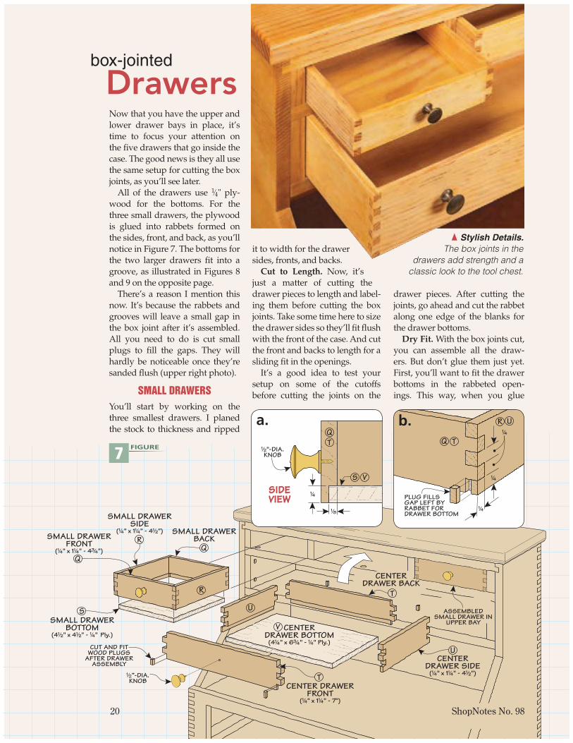
Now that you have the upper and lower drawer bays in place, it’s time to focus your attention on the fi ve drawers that go inside the case. The good news is they all use the same setup for cutting the box joints, as you’ll see later.
All of the drawers use 1⁄4" ply-wood for the bottoms. For the three small drawers, the plywood is glued into rabbets formed on the sides, front, and back, as you’ll notice in Figure 7. The bottoms for the two larger drawers fi t into a groove, as illustrated in Figures 8 and 9 on the opposite page.
There’s a reason I mention this now. It’s because the rabbets and grooves will leave a small gap in the box joint after it’s assembled. All you need to do is cut small plugs to fi ll the gaps. They will hardly be noticeable once they’re sanded fl ush (upper right photo).
SMALL DRAWERSYou’ll start by working on the three smallest drawers. I planed the stock to thickness and ripped
it to width for the drawer sides, fronts, and backs.
Cut to Length. Now, it’s just a matter of cutting the drawer pieces to length and label-ing them before cutting the box joints. Take some time here to size the drawer sides so they’ll fi t fl ush with the front of the case. And cut the front and backs to length for a sliding fi t in the openings.
It’s a good idea to test your setup on some of the cutoffs before cutting the joints on the
drawer pieces. After cutting the joints, go ahead and cut the rabbet along one edge of the blanks for the drawer bottoms.
Dry Fit. With the box joints cut, you can assemble all the draw-ers. But don’t glue them just yet. First, you’ll want to fi t the drawer bottoms in the rabbeted open-ings. This way, when you glue
box-jointed
Drawers
{ Stylish Details. The box joints in the
drawers add strength and a classic look to the tool chest.
CUT AND FITWOOD PLUGS
AFTER DRAWERASSEMBLY
U
T
S
RQ
SMALL DRAWERSIDE
(!/4" x 1!/4" - 4!/2") SMALL DRAWERBACK
R
SMALL DRAWERFRONT
(!/4" x 1!/4" - 4#/4")Q
SMALL DRAWERBOTTOM
(4!/2" x 4!/2" - !/4" Ply.)
!/2”-DIA.KNOB
CENTER DRAWERFRONT
(!/4" x 1!/4" - 7")
CENTERDRAWER SIDE
(!/4" x 1!/4" - 4!/2")
U
T
CENTERDRAWER BACK
CENTERDRAWER BOTTOM
(4!/4" x 6#/4" - !/4" Ply.)
V
ASSEMBLEDSMALL DRAWER IN
UPPER BAY
20 ShopNotes No. 98
7 FIGURE
SIDEVIEW
S V
!/2"-DIA.KNOB
!/8
!/4
TQ
a. U
T
R
Q
!/4
!/4
!/4
PLUG FILLSGAP LEFT BYRABBET FORDRAWER BOTTOM
b.
s098_020.indd 20 1/23/2008 4:40:21 PM
www.ShopNotes.com 21
&/8"-DIA.KNOB
LOWERDRAWER BACK(!/4" x 2#/4" - 16!/2")
LOWER DRAWERSIDE
(!/2" x 2#/4" - 10!/2")
LOWER DRAWERFRONT
(!/2" x 2#/4" - 16!/2")
2!/2
CL
PLUG
Z
AA
AA
LOWER DRAWERBOTTOM
(10" x 16" - !/4" Ply.)
BB
Z
&/8"-DIA.KNOB
!/4
!/4
!/4
BB
Z
a.
9
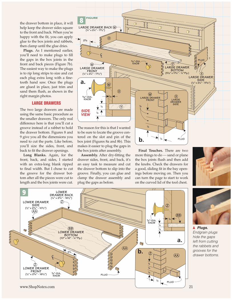
{ Plugs. Endgrain plugs hide the gaps left from cutting the rabbets and grooves for the drawer bottoms.
the drawer bottom in place, it will help keep the drawer sides square to the front and back. When you’re happy with the fi t, you can apply glue to the box joints and rabbets, then clamp until the glue dries.
Plugs. As I mentioned earlier, you’ll need to make plugs to fi ll the gaps in the box joints in the front and back pieces (Figure 7b). The easiest way to make the plugs is to rip long strips to size and cut each plug extra long with a fi ne-tooth hand saw. Once the plugs are glued in place, just trim and sand them fl ush, as shown in the right margin photos.
LARGE DRAWERSThe two large drawers are made using the same basic procedure as the smaller drawers. The only real difference here is that you’ll cut a groove instead of a rabbet to hold the drawer bottom. Figures 8 and 9 give you all the dimensions you need to cut the parts. Like before, you’ll size the sides, front, and back to fi t the drawer openings.
Long Blanks. Again, for the front, back, and sides, I started with an extra-long blank ripped to fi nal width. But I chose to cut the groove for the drawer bot-tom after all the pieces were cut to length and the box joints were cut.
The reason for this is that I wanted to be sure to locate the groove cen-tered on the slot and pin of the box joint (Figures 8a and 8b). This makes it easier to plug the gaps in the box joints after assembly.
Assembly. After dry-fi tting the drawer sides, front, and back, it’s an easy task to measure and cut the drawer bottom to slip into the groove. Finally, you can glue and clamp the drawer assembly and plug the gaps as before.
Final Touches. There are two more things to do — sand or plane the box joints fl ush and then add the knobs. Check the drawers for a good, sliding fi t in the bay open-ings before moving on. Then you can turn the page to start to work on the curved lid of the tool chest.
PLUG
!/4
!/2
AAZ
!/4
!/4
b.
Y
W
%/8"-DIA.KNOB
LARGE DRAWER BACK(!/4" x 2!/4" - 17!/2")
XLARGE DRAWER
SIDE(!/4" x 2!/4" - 5#/8")
X
LARGE DRAWERFRONT
(!/4" x 2!/4" - 17!/2")
WLARGE DRAWER
BOTTOM(5!/8" x 17!/4" - !/4" Ply.)
2#/8
CLPLUG
SIDEVIEW
%/8"-DIA.KNOB
!/8
!/4
!/4
Y
X
Wa.
8 FIGURE
!/4
!/4
!/4 PLUG
XWLARGE
DRAWERSIDE
LARGE DRAWERFRONT
b.
s098_020.indd 21 1/23/2008 4:40:38 PM
The attention-grabbing part of this tool chest is the curved lid you see at right. At fi rst glance, the “curved” box joints look like they’d be diffi cult to make. But it’s really a simple process.
Now, I’m not going to kid you. Making the curved lid isn’t com-plicated, but it will take some patience and challenge your woodworking skills.
There are fi fteen pieces that make up the lid. So, it takes some fi ne-tuning and tweaking to get everything to go together and fi t right on the case. But by following the steps below, you’ll be on your way to a great-looking tool chest.
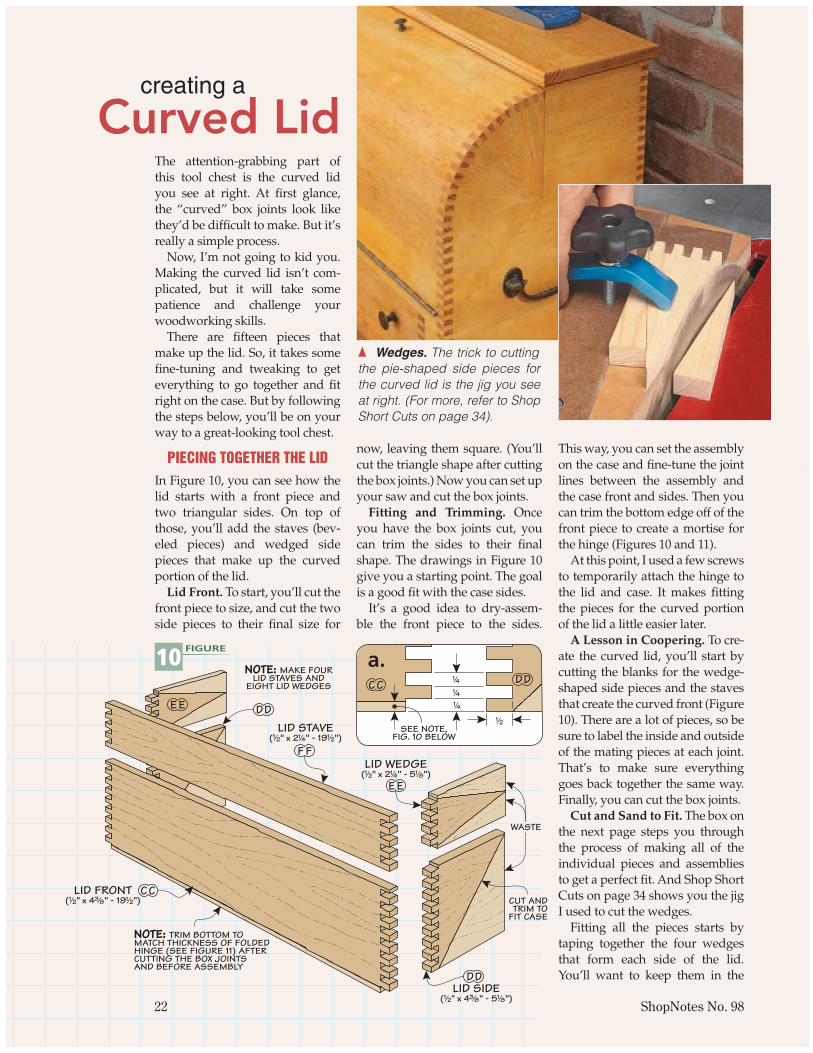
PIECING TOGETHER THE LIDIn Figure 10, you can see how the lid starts with a front piece and two triangular sides. On top of those, you’ll add the staves (bev-eled pieces) and wedged side pieces that make up the curved portion of the lid.
Lid Front. To start, you’ll cut the front piece to size, and cut the two side pieces to their fi nal size for
now, leaving them square. (You’ll cut the triangle shape after cutting the box joints.) Now you can set up your saw and cut the box joints.
Fitting and Trimming. Once you have the box joints cut, you can trim the sides to their fi nal shape. The drawings in Figure 10 give you a starting point. The goal is a good fi t with the case sides.
It’s a good idea to dry-assem-ble the front piece to the sides.
This way, you can set the assembly on the case and fi ne-tune the joint lines between the assembly and the case front and sides. Then you can trim the bottom edge off of the front piece to create a mortise for the hinge (Figures 10 and 11).
At this point, I used a few screws to temporarily attach the hinge to the lid and case. It makes fi tting the pieces for the curved portion of the lid a little easier later.
A Lesson in Coopering. To cre-ate the curved lid, you’ll start by cutting the blanks for the wedge-shaped side pieces and the staves that create the curved front (Figure 10). There are a lot of pieces, so be sure to label the inside and outside of the mating pieces at each joint. That’s to make sure everything goes back together the same way. Finally, you can cut the box joints.
Cut and Sand to Fit. The box on the next page steps you through the process of making all of the individual pieces and assemblies to get a perfect fi t. And Shop Short Cuts on page 34 shows you the jig I used to cut the wedges.
Fitting all the pieces starts by taping together the four wedges that form each side of the lid. You’ll want to keep them in the
creating a
Curved Lid
LID FRONT(!/2" x 4#/8" - 19!/2")
DD
CC
FF
EE
LID WEDGE(!/2" x 2!/4" - 5!/8")
LID STAVE(!/2" x 2!/4" - 19!/2")
LID SIDE(!/2" x 4#/8" - 5!/8")
WASTE
NOTE: TRIM BOTTOM TOMATCH THICKNESS OF FOLDEDHINGE (SEE FIGURE 11) AFTERCUTTING THE BOX JOINTSAND BEFORE ASSEMBLY
EE DD
CUT ANDTRIM TO
FIT CASE
NOTE: MAKE FOURLID STAVES AND
EIGHT LID WEDGES
22 ShopNotes No. 98
10 FIGURE
DDCC
SEE NOTE,FIG. 10 BELOW
!/2
!/4
!/4
!/4
a.
{ Wedges. The trick to cutting the pie-shaped side pieces for the curved lid is the jig you see at right. (For more, refer to Shop Short Cuts on page 34).
s098_022.indd 22 1/23/2008 5:31:18 PM

DDLID
SIDE
DD
1!/16" CONTINUOUSHINGE
NOTE: WITH LIDFRONT FLUSH TOFRONT OF CASE,
SIDE POINTMUST FIT HERE
LID FRONTCC
same orientation during the fi tting process. Now it’s just a matter of taking a little time to tweak the fi t of each wedge to get perfect joint lines between each other and the sides of the case.
The next step is to dry-assemble each stave with its two mating wedges. Then you transfer the angle of the wedge onto the end of the stave to rip their beveled edges. Once that’s done, you can glue and sand each stave assembly before moving on. Just be sure to take it easy and check the fi t often to avoid problems later on.
Step-by-Step: Trim and Fit
At this point, all that’s left to do is take care of the fi nal details of fi tting and assembling the lid of the tool chest.
You’ll start by fi tting all the wedged side pieces together (Step 1). Then you’ll mate them up with their staves to rip the bevels (Steps 2 and 3). Now is a good time to check the fi t with the case and with the other stave assemblies, keeping them in the same order as before. Then you can glue and clamp each stave assem-bly (Step 4), using a scrap block to keep things square. Finally, some careful sanding will guarantee a good fi t (Step 5).
www.ShopNotes.com 23
EXTEND LINE OF WEDGEEDGE ACROSS END
OF STAVE WITH PENCIL
STRAIGHT EDGE
TAPE HOLDS ASSEMBLYFOR FITTING TO CASE
LIDSTAVE
PUSHBLOCK
NOTE: A FEW LAYERSOF TAPE EQUAL TO THETHICKNESS OF SANDPAPERACT AS A SPACER SANDPAPER
CLAMP ACROSS ASSEMBLYTO DRAW JOINTS TIGHT
NOTE: CUT SCRAP PIECE TOLENGTH TO HOLD ASSEMBLYSQUARE WHILE CLAMPING
11 FIGURE
FRONT VIEW
CCHINGE
LID FRONT
CASE FRONT
DD
HINGEWITH
SCREWS
LID SIDE
CC
CASEDIVIDER
a.
CHECK FORGAPS ANDSAND TO FIT
SIDEVIEW
LIDSTAVE
LIDWEDGE
STAVEWASTE
END VIEWTILT BLADETO MATCH
LAYOUT LINE
LID STAVE
PUSHBLOCK
b.
a.
a. a.
1 Completing an Arc. Fitting the four wedges for each side of the lid means aiming for tight joints between them. Use
tape to keep everything together as you work.
2 Marking the Bevels. Using the mating wedges, transfer the bevel angle to the staves. These marks will serve as
guidelines for setting the tilt of your saw blade.3 Ripping Bevels. With a push block, rip the bevels on
each side of the stave, being careful to check the fence position before each cut. Stay close to the layout line.
4 Square Glue-Up. After applying glue, a spacer helps keep the assembly square as you apply clamping
pressure to draw the box joints tight.5 Sanding the Staves. Carefully sand the edges of the
staves fl ush with the wedges. Be careful not to sand the wedges in order to maintain a good joint line.
s098_022.indd 23 1/23/2008 6:09:35 PM