Embed Size (px)
Citation preview
OVERSEAS ROAD NOTEVol 2 7
BridgeInspector’sHandbook
TRL LimitedCrowthorne, Berkshire, United Kingdom
Guidance on the use of this handbook is given in thecomplementary publication:
Overseas Road Note 7, (Volume 1)
A Guide to Bridge Inspection and Data Systems for DistrictEngineers.
First edition published by the Transport and Road ResearchLaboratory, 1988
Reprinted with minor amendments by TRL Limited, 2004
Copyright © 1988, 2004
Limited extracts from the text may be reproduced, providedthe source is acknowledged.
For more extensive reproduction please write to:
The Director, TRL Limited.
OVERSEAS ROAD NOTES
Overseas Road Notes are prepared principally for road andtransport authorities in countries receiving technicalassistance from the British Government. A limited number ofcopies are available to other organisations and to individualswith an interest in roads overseas.
Enquiries should be made to:
TRL LimitedOld Wokingham RoadCrowthorneBerkshireRG45 6AUEngland

ACKNOWLEDGEMENTS
This handbook was drafted by Mr J D Parry of theOverseas Unit, TRRL (now TRL Limited). It is based on anoriginal text by Rendel, Palmer and Tritton, ConsultingEngineers and is published by permission of the Director,Transport and Road Research Laboratory (now TRL Limited).
FOREWORD
In many developing countries there is a shortage of trainedbridge engineers. Where this is so, other personnel must beused for routine bridge inspections, or the bridges areneglected and deteriorate. Using this handbook, a personwith experience, but little formal technical training, such as aroad maintenance supervisor, should be able to carry outroutine bridge inspections on the majority of bridges.
This handbook utilises an inspector’s report form, which alsoprovides a check list of items to be inspected. For each item,detailed but simple, advice is given on what to look for.
Large or unusual bridges, such as suspension bridges, arebeyond the scope of this handbook, and should therefore beinspected by an engineer.
Both technical content and language have been simplified tomake this handbook usable by people whose knowledge ofengineering, and/or English, is not highly developed.
It must be stressed that this handbook aims only to supportand guide a suitable person in how to inspect a bridge onbehalf of the engineer. The final responsibility must lie withthe engineer.
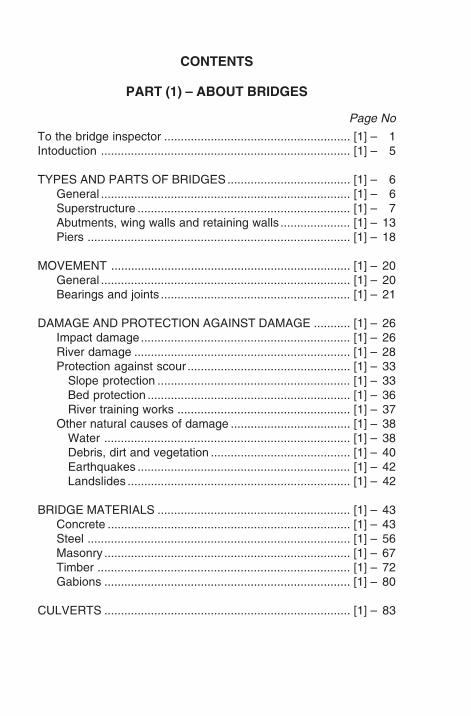
CONTENTS
PART (1) – ABOUT BRIDGES
Page No
To the bridge inspector ........................................................ [1] – 1Intoduction ........................................................................... [1] – 5
TYPES AND PARTS OF BRIDGES..................................... [1] – 6General ........................................................................... [1] – 6Superstructure ................................................................ [1] – 7Abutments, wing walls and retaining walls ..................... [1] – 13Piers ............................................................................... [1] – 18
MOVEMENT ........................................................................ [1] – 20General ........................................................................... [1] – 20Bearings and joints ......................................................... [1] – 21
DAMAGE AND PROTECTION AGAINST DAMAGE ........... [1] – 26Impact damage............................................................... [1] – 26River damage ................................................................. [1] – 28Protection against scour ................................................. [1] – 33
Slope protection .......................................................... [1] – 33Bed protection ............................................................. [1] – 36River training works .................................................... [1] – 37
Other natural causes of damage .................................... [1] – 38Water .......................................................................... [1] – 38Debris, dirt and vegetation .......................................... [1] – 40Earthquakes ................................................................ [1] – 42Landslides ................................................................... [1] – 42
BRIDGE MATERIALS .......................................................... [1] – 43Concrete ......................................................................... [1] – 43Steel ............................................................................... [1] – 56Masonry .......................................................................... [1] – 67Timber ............................................................................ [1] – 72Gabions .......................................................................... [1] – 80
CULVERTS .......................................................................... [1] – 83
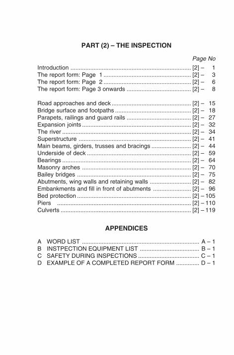
PART (2) – THE INSPECTION
Page No
Introduction ......................................................................... [2] – 1The report form: Page 1 ..................................................... [2] – 3The report form: Page 2 ..................................................... [2] – 6The report form: Page 3 onwards ....................................... [2] – 8
Road approaches and deck ................................................ [2] – 15Bridge surface and footpaths .............................................. [2] – 18Parapets, railings and guard rails ....................................... [2] – 27Expansion joints .................................................................. [2] – 32The river .............................................................................. [2] – 34Superstructure .................................................................... [2] – 41Main beams, girders, trusses and bracings ........................ [2] – 44Underside of deck ............................................................... [2] – 59Bearings .............................................................................. [2] – 64Masonry arches .................................................................. [2] – 70Bailey bridges ..................................................................... [2] – 75Abutments, wing walls and retaining walls ......................... [2] – 82Embankments and fill in front of abutments ....................... [2] – 96Bed protection ..................................................................... [2] – 105Piers ................................................................................. [2] – 110Culverts ............................................................................... [2] – 119
APPENDICES
A WORD LIST ....................................................................... A – 1B INSTPECTION EQUIPMENT LIST .................................... B – 1C SAFETY DURING INSPECTIONS ..................................... C – 1D EXAMPLE OF A COMPLETED REPORT FORM .............. D – 1

[1] – 1
TO THE BRIDGE INSPECTOR
Often, a bridge inspector is a qualified engineer. Butsometimes, there are not enough engineers to do this work,and other people become bridge inspectors.
Inspecting a bridge is a very responsible job. It is not an easyjob, and there are many things to learn before you caninspect a bridge properly. This handbook explains the thingsyou need to know to inspect a bridge.
BEFORE YOU INSPECT A BRIDGE, YOU MUST READPART [1] OF THIS HANDBOOK AND UNDERSTANDEVERYTHING IN IT.
Part [1] of this handbook tells you the names of differentparts of bridges. It explains the different kinds of bridges andtells you how bridges can be damaged. It also gives youbasic information about concrete, steel, masonry and timber,as they are used in bridges.
Part [2] of this handbook helps you to inspect a bridge and fillin an inspection report form. You must read Part [1], so thatyou will understand the engineering terms used in Part [2].Before you inspect a bridge, you should read Part [2]. Whenyou go to inspect a bridge, take this book with you, as it willtell you what things must be checked and how to fill in theinspection report form.
If you have some experience of bridges, the information inthe book will not be difficult for you.
[1] – 2
If you speak English in your job, you will already know manyof the engineering words which are used. If not, you will needto learn some new words. To help you there is a word list inAppendix A.
Appendix A is at the back of this handbook on pages A - 1 toA - 8. It is a list of the engineering words and their meanings.The first time each of these words is used in the handbook, itis printed in CAPITALS, so you will know you can find it inthe word list.
A small handbook like this one cannot teach you everythingabout bridges. Sometimes you must ask an engineer toexplain things to you. The engineer you are working forshould be willing to help you with any problems.
Appendix B is a list of equipment you will need when you areinspecting bridges. You may think of other useful things toadd to this list. You should keep all these things in goodcondition and check them after each inspection, so that youwill have a full set of tools and equipment when you arrive atthe next bridge.
Appendix C is about safety and is very important. Pleaseread this carefully.
Appendix D is an example of a completed inspection reportform. When you inspect a bridge, your report form will haveticks in different places. The number in the first column, onthe left side of the page, tells you which page to look at inPart [2] of this book, if you need help with that part of theinspection.
[1] – 3
This handbook does not tell you about suspension bridges,cable-stayed bridges or movable bridges, and it does not tellyou about very large bridges. These bridges must beinspected by a bridge engineer.
A bridge inspector must know many things and he must alsohave many good qualities.
There are 3 qualities which are very important:
1. A bridge inspector must be a careful worker. You mustalways look at a bridge carefully and fill in the inspectionreport form carefully It is better to be slow and careful.
2. A bridge inspector must be a safe worker. You must bein good health and fit, so you can climb over parts of abridge safely. Safety is very important and you mustnever take unnecessary risks.
3. A bridge inspector must be a responsible person. A goodinspector can help prevent road accidents and keep theroads open to traffic.

[1] – 4
[1] – 5
PART (1) – ABOUT BRIDGES
INTRODUCTION
Bridges can be the weak links in a road network. They mustbe very well maintained in order to keep the roads open totraffic. Most of the bridges you will inspect carry a road overa river. Culverts are included too, because they are like smallbridges and if a culvert collapses the road may have to beclosed.
As an inspector you will be looking for damage which hasalready happened, or will soon happen. You will be looking atthe bridge, the material it is made from, and also the river.The river is important because it can damage the bridge.
To understand about damage to bridges, you mustunderstand something about the materials used in bridgesThe materials most commonly used for bridge constructionare concrete, steel, masonry and timber. You will find noteson these materials at the end of Part [1].
[1] – 6
TYPES AND PARTS OF BRIDGES
GENERAL
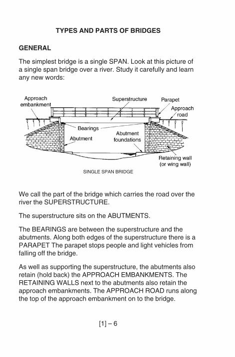
The simplest bridge is a single SPAN. Look at this picture ofa single span bridge over a river. Study it carefully and learnany new words:
We call the part of the bridge which carries the road over theriver the SUPERSTRUCTURE.
The superstructure sits on the ABUTMENTS.
The BEARINGS are between the superstructure and theabutments. Along both edges of the superstructure there is aPARAPET The parapet stops people and light vehicles fromfalling off the bridge.
As well as supporting the superstructure, the abutments alsoretain (hold back) the APPROACH EMBANKMENTS. TheRETAINING WALLS next to the abutments also retain theapproach embankments. The APPROACH ROAD runs alongthe top of the approach embankment on to the bridge.
SINGLE SPAN BRIDGE
[1] – 7
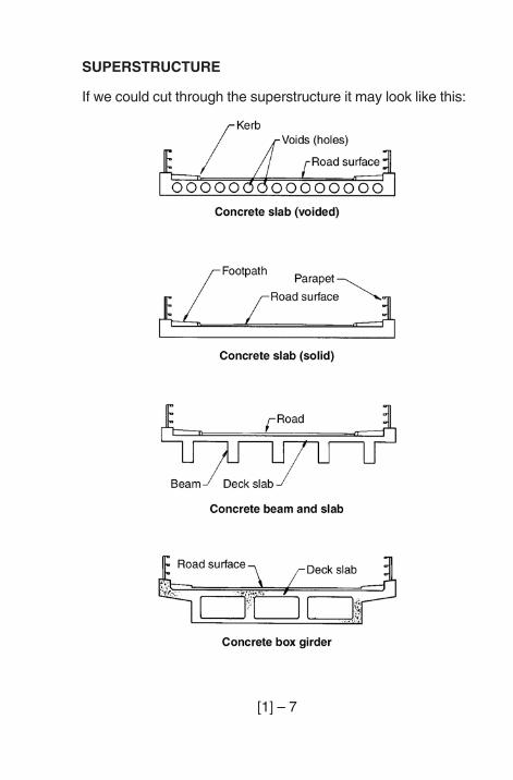
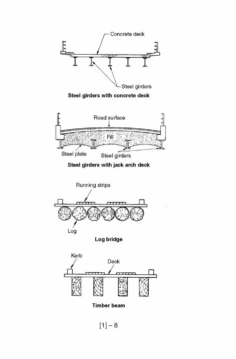
SUPERSTRUCTURE
If we could cut through the superstructure it may look like this:
[1] – 8
[1] – 9
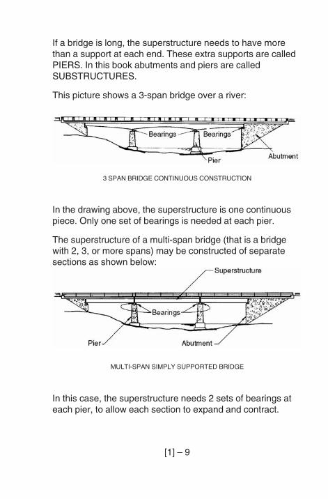
If a bridge is long, the superstructure needs to have morethan a support at each end. These extra supports are calledPIERS. In this book abutments and piers are calledSUBSTRUCTURES.
This picture shows a 3-span bridge over a river:
In the drawing above, the superstructure is one continuouspiece. Only one set of bearings is needed at each pier.
The superstructure of a multi-span bridge (that is a bridgewith 2, 3, or more spans) may be constructed of separatesections as shown below:
In this case, the superstructure needs 2 sets of bearings ateach pier, to allow each section to expand and contract.
3 SPAN BRIDGE CONTINUOUS CONSTRUCTION
MULTI-SPAN SIMPLY SUPPORTED BRIDGE
[1] – 10
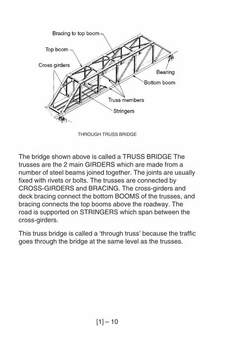
The bridge shown above is called a TRUSS BRIDGE Thetrusses are the 2 main GIRDERS which are made from anumber of steel beams joined together. The joints are usuallyfixed with rivets or bolts. The trusses are connected byCROSS-GIRDERS and BRACING. The cross-girders anddeck bracing connect the bottom BOOMS of the trusses, andbracing connects the top booms above the roadway. Theroad is supported on STRINGERS which span between thecross-girders.
This truss bridge is called a ‘through truss’ because the trafficgoes through the bridge at the same level as the trusses.
THROUGH TRUSS BRIDGE
[1] – 11
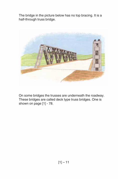
The bridge in the picture below has no top bracing. It is ahalf-through truss bridge.
On some bridges the trusses are underneath the roadway.These bridges are called deck type truss bridges. One isshown on page [1] - 78.
[1] – 12
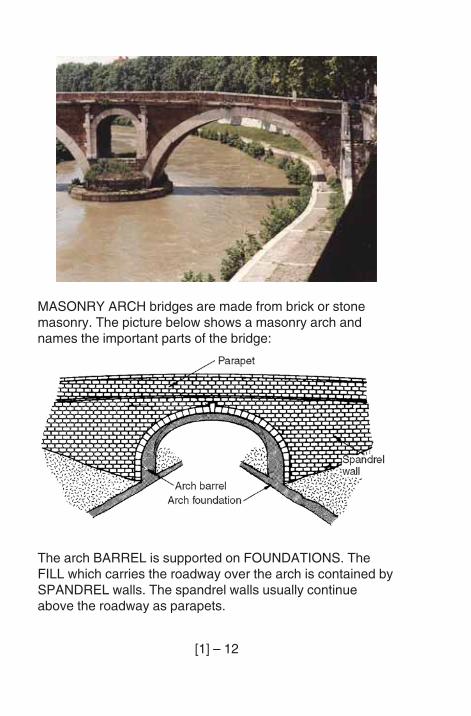
MASONRY ARCH bridges are made from brick or stonemasonry. The picture below shows a masonry arch andnames the important parts of the bridge:
The arch BARREL is supported on FOUNDATIONS. TheFILL which carries the roadway over the arch is contained bySPANDREL walls. The spandrel walls usually continueabove the roadway as parapets.
[1] – 13
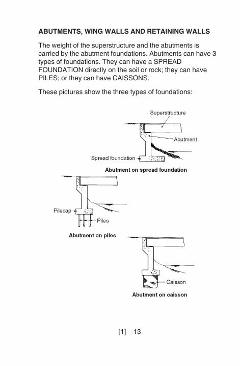
ABUTMENTS, WING WALLS AND RETAINING WALLS
The weight of the superstructure and the abutments iscarried by the abutment foundations. Abutments can have 3types of foundations. They can have a SPREADFOUNDATION directly on the soil or rock; they can havePILES; or they can have CAISSONS.
These pictures show the three types of foundations:
[1] – 14
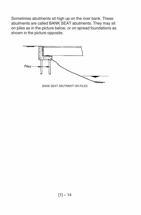
Sometimes abutments sit high up on the river bank. Theseabutments are called BANK SEAT abutments. They may siton piles as in the picture below, or on spread foundations asshown in the picture opposite.
BANK SEAT ABUTMENT ON PILES
[1] – 15
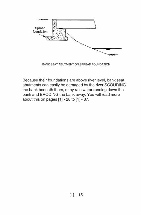
Because their foundations are above river level, bank seatabutments can easily be damaged by the river SCOURINGthe bank beneath them, or by rain water running down thebank and ERODING the bank away. You will read moreabout this on pages [1] - 28 to [1] - 37.
BANK SEAT ABUTMENT ON SPREAD FOUNDATION
[1] – 16
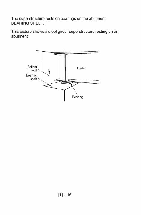
The superstructure rests on bearings on the abutmentBEARING SHELF.
This picture shows a steel girder superstructure resting on anabutment:
Girder
[1] – 17
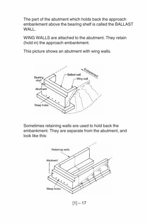
The part of the abutment which holds back the approachembankment above the bearing shelf is called the BALLASTWALL.
WING WALLS are attached to the abutment. They retain(hold in) the approach embankment.
This picture shows an abutment with wing walls.
Sometimes retaining walls are used to hold back theembankment. They are separate from the abutment, andlook like this:
[1] – 18
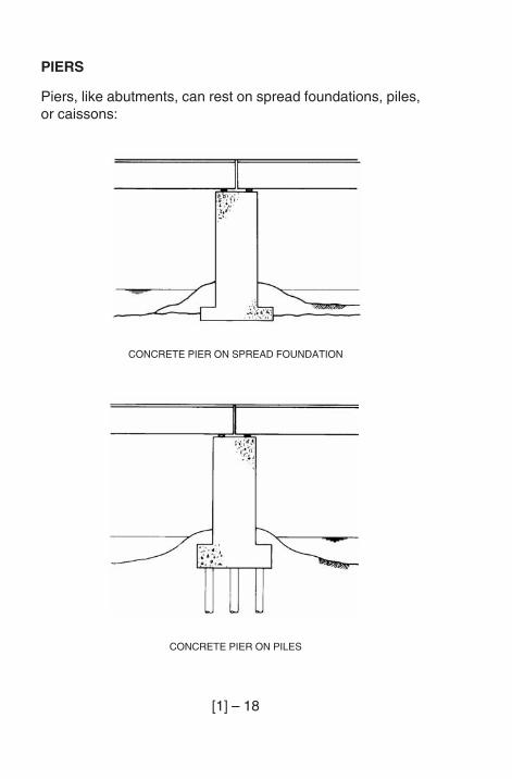
PIERS
Piers, like abutments, can rest on spread foundations, piles,or caissons:
CONCRETE PIER ON SPREAD FOUNDATION
CONCRETE PIER ON PILES
[1] – 19
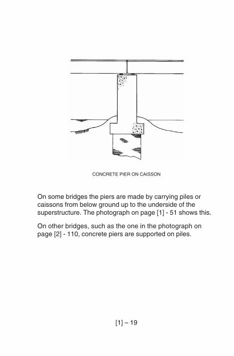
On some bridges the piers are made by carrying piles orcaissons from below ground up to the underside of thesuperstructure. The photograph on page [1] - 51 shows this.
On other bridges, such as the one in the photograph onpage [2] - 110, concrete piers are supported on piles.
CONCRETE PIER ON CAISSON
[1] – 20
MOVEMENT
GENERAL
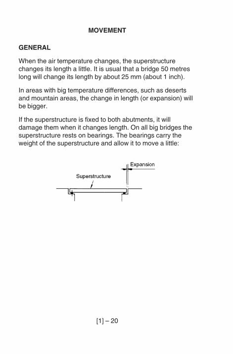
When the air temperature changes, the superstructurechanges its length a little. It is usual that a bridge 50 metreslong will change its length by about 25 mm (about 1 inch).
In areas with big temperature differences, such as desertsand mountain areas, the change in length (or expansion) willbe bigger.
If the superstructure is fixed to both abutments, it willdamage them when it changes length. On all big bridges thesuperstructure rests on bearings. The bearings carry theweight of the superstructure and allow it to move a little:
[1] – 21
BEARINGS AND JOINTS
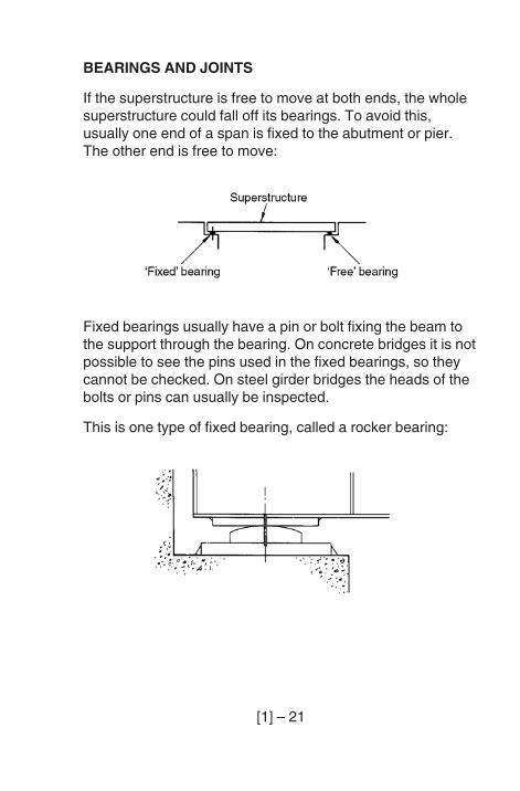
If the superstructure is free to move at both ends, the wholesuperstructure could fall off its bearings. To avoid this,usually one end of a span is fixed to the abutment or pier.The other end is free to move:
Fixed bearings usually have a pin or bolt fixing the beam tothe support through the bearing. On concrete bridges it is notpossible to see the pins used in the fixed bearings, so theycannot be checked. On steel girder bridges the heads of thebolts or pins can usually be inspected.
This is one type of fixed bearing, called a rocker bearing:
[1] – 22
It is important that you know which bearings are fixed, andwhich are free. To find this out, look on the bridge recordcard before you go to the bridge.
There are many different types of free bearings, butmovement is usually allowed in one of three ways:
– change of shape of rubber bearings;
– sliding between special surfaces;
– rolling on steel rollers.
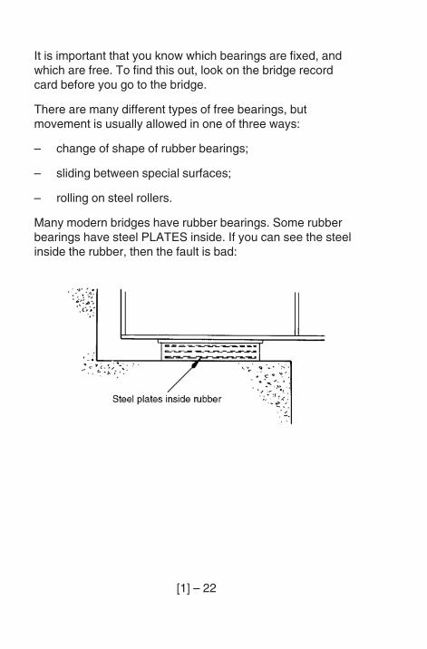
Many modern bridges have rubber bearings. Some rubberbearings have steel PLATES inside. If you can see the steelinside the rubber, then the fault is bad:
[1] – 23
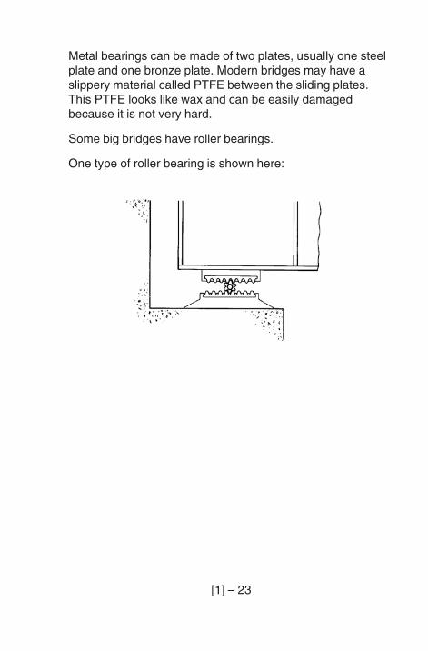
Metal bearings can be made of two plates, usually one steelplate and one bronze plate. Modern bridges may have aslippery material called PTFE between the sliding plates.This PTFE looks like wax and can be easily damagedbecause it is not very hard.
Some big bridges have roller bearings.
One type of roller bearing is shown here:
[1] – 24
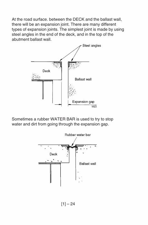
At the road surface. between the DECK and the ballast wall,there will be an expansion joint. There are many differenttypes of expansion joints. The simplest joint is made by usingsteel angles in the end of the deck, and in the top of theabutment ballast wall.
Sometimes a rubber WATER BAR is used to try to stopwater and dirt from going through the expansion gap.
[1] – 25
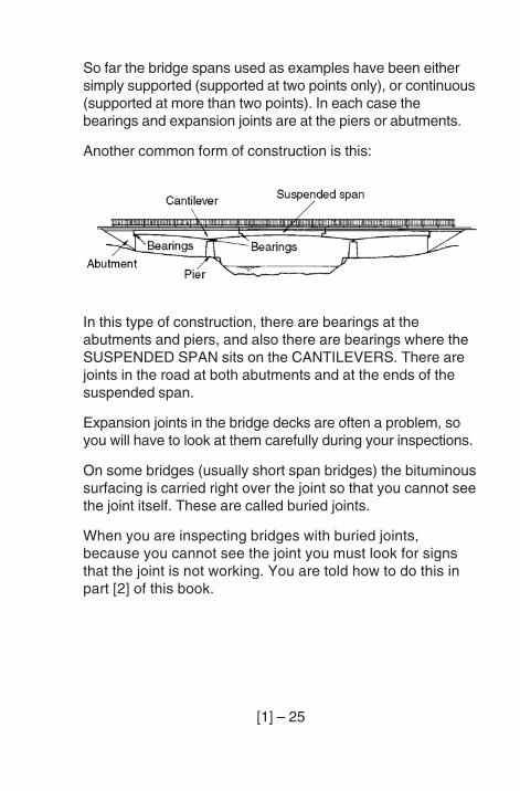
So far the bridge spans used as examples have been eithersimply supported (supported at two points only), or continuous(supported at more than two points). In each case thebearings and expansion joints are at the piers or abutments.
Another common form of construction is this:
In this type of construction, there are bearings at theabutments and piers, and also there are bearings where theSUSPENDED SPAN sits on the CANTILEVERS. There arejoints in the road at both abutments and at the ends of thesuspended span.
Expansion joints in the bridge decks are often a problem, soyou will have to look at them carefully during your inspections.
On some bridges (usually short span bridges) the bituminoussurfacing is carried right over the joint so that you cannot seethe joint itself. These are called buried joints.
When you are inspecting bridges with buried joints,because you cannot see the joint you must look for signsthat the joint is not working. You are told how to do this inpart [2] of this book.
[1] – 26
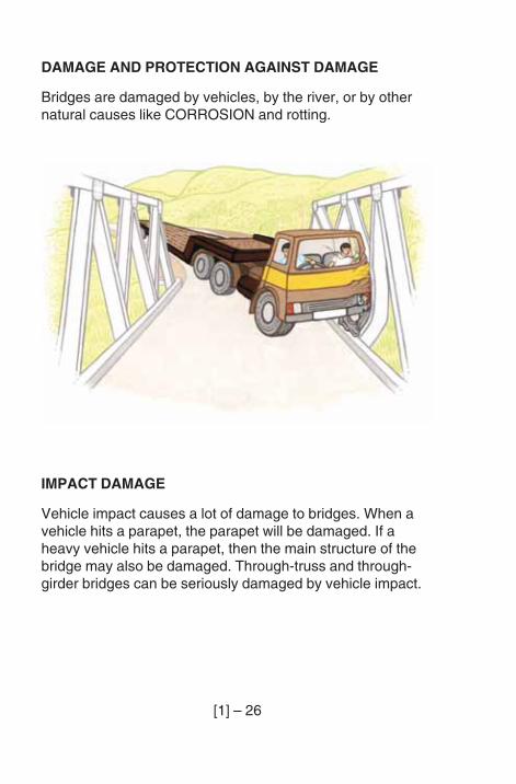
DAMAGE AND PROTECTION AGAINST DAMAGE
Bridges are damaged by vehicles, by the river, or by othernatural causes like CORROSION and rotting.
IMPACT DAMAGE
Vehicle impact causes a lot of damage to bridges. When avehicle hits a parapet, the parapet will be damaged. If aheavy vehicle hits a parapet, then the main structure of thebridge may also be damaged. Through-truss and through-girder bridges can be seriously damaged by vehicle impact.
[1] – 27
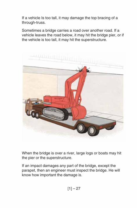
If a vehicle Is too tall, it may damage the top bracing of athrough-truss.
Sometimes a bridge carries a road over another road. If avehicle leaves the road below, it may hit the bridge pier, or ifthe vehicle is too tall, it may hit the superstructure.
When the bridge is over a river, large logs or boats may hitthe pier or the superstructure.
If an impact damages any part of the bridge, except theparapet, then an engineer must inspect the bridge. He willknow how important the damage is.
[1] – 28
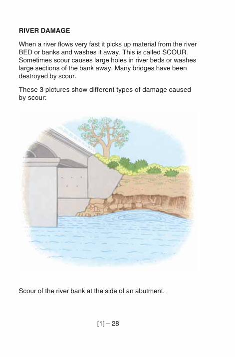
RIVER DAMAGE
When a river flows very fast it picks up material from the riverBED or banks and washes it away. This is called SCOUR.Sometimes scour causes large holes in river beds or washeslarge sections of the bank away. Many bridges have beendestroyed by scour.
These 3 pictures show different types of damage causedby scour:
Scour of the river bank at the side of an abutment.
[1] – 29
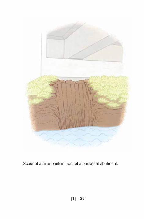
Scour of a river bank in front of a bankseat abutment.
[1] – 30
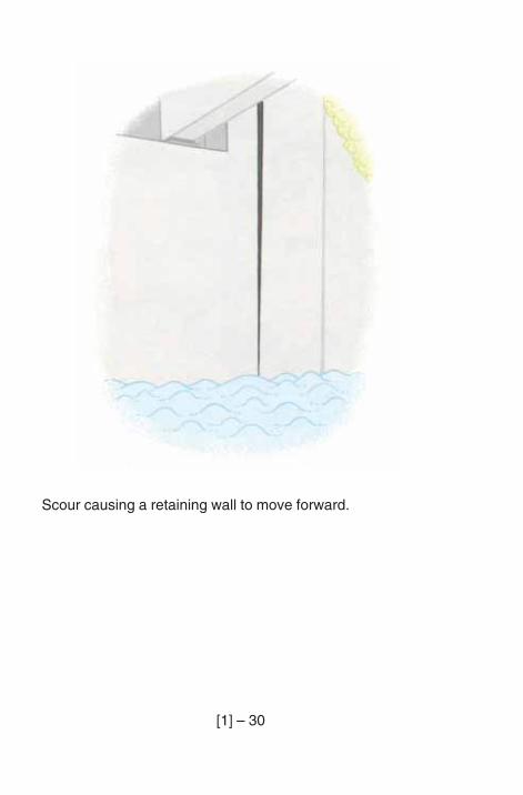
Scour causing a retaining wall to move forward.
[1] – 31
Rivers can easily damage or destroy bridges. Usually bridgesare damaged when the river is too big to go through thewaterway under the bridge, or when the river changes its path.
There are 3 reasons why a river may not be able to gothrough the waterway of a bridge.
1. A river can grow and become too big for the waterway.
2. The waterway under the bridge can be blocked by partsof old bridges, trees, fences and other debris.
3. The waterway under the bridge was not made bigenough.
If there is a flood which is too big for the waterway under thebridge, the river may do 3 things:
1. Wash away the bridge.
2. Wash away the road embankment and the road, and goround the bridge.
3. Wash away the fill in front of the abutments, and scourbig holes in the river bed.
If the waterway is too small, another bridge or some culvertsmay be needed to carry the extra floodwater.
[1] – 32
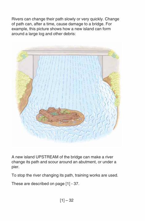
Rivers can change their path slowly or very quickly. Changeof path can, after a time, cause damage to a bridge. Forexample, this picture shows how a new island can formaround a large log and other debris:
A new island UPSTREAM of the bridge can make a riverchange its path and scour around an abutment, or under apier.
To stop the river changing its path, training works are used.
These are described on page [1] - 37.
[1] – 33
PROTECTION AGAINST SCOUR
If the river is causing scour, then the road embankment, theabutments and the piers can be protected with slopeprotection and bed protection.
Slope protection
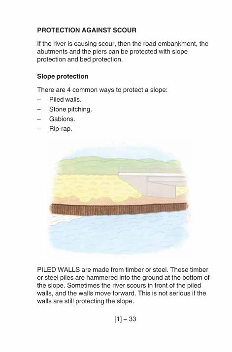
There are 4 common ways to protect a slope:
– Piled walls.
– Stone pitching.
– Gabions.
– Rip-rap.
PILED WALLS are made from timber or steel. These timberor steel piles are hammered into the ground at the bottom ofthe slope. Sometimes the river scours in front of the piledwalls, and the walls move forward. This is not serious if thewalls are still protecting the slope.
[1] – 34
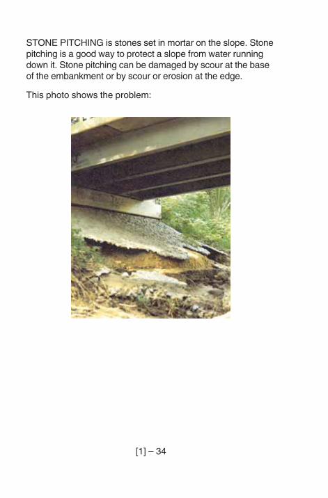
STONE PITCHING is stones set in mortar on the slope. Stonepitching is a good way to protect a slope from water runningdown it. Stone pitching can be damaged by scour at the baseof the embankment or by scour or erosion at the edge.
This photo shows the problem:
[1] – 35
GABIONS (or RENO MATTRESSES) are wire baskets filledwith stones. They are often used as slope protection.Because they can change shape and settle a lot without anydamage, gabions are good for protecting slopes.
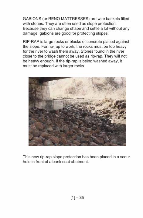
RIP-RAP is large rocks or blocks of concrete placed againstthe slope. For rip-rap to work, the rocks must be too heavyfor the river to wash them away. Stones found in the riverclose to the bridge cannot be used as rip-rap. They will notbe heavy enough. If the rip-rap is being washed away, itmust be replaced with larger rocks.
This new rip-rap slope protection has been placed in a scourhole in front of a bank seat abutment.
[1] – 36
Bed protection
Sometimes, to protect the bridge from scour, part or all of thebed of the river at the bridge is covered with stone pitching,concrete or gabions (or reno mattresses).
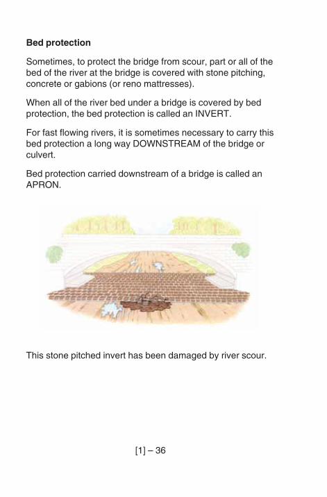
When all of the river bed under a bridge is covered by bedprotection, the bed protection is called an INVERT.
For fast flowing rivers, it is sometimes necessary to carry thisbed protection a long way DOWNSTREAM of the bridge orculvert.
Bed protection carried downstream of a bridge is called anAPRON.
This stone pitched invert has been damaged by river scour.
[1] – 37
River training works
River training works are used to keep a river on its path.
There are 4 common ways of river training:
– SHEET PILED WALLS of steel or timber (picture onpage [1] -33);
– embankments protected by rip-rap or gabions;
– groynes made from steel or timber piles or gabions;
– trees protected by gabions.
GROYNES are lines of piles or gabions which are placedpart way across the river from the river bank.
If trees can be grown, their roots help to keep the bank inplace. Gabions are sometimes used to protect the youngtrees.
River training works can be made of many different types ofmaterial and with different methods of construction. If you arenot sure about the methods used in your district ask theengineer.
[1] – 38
OTHER NATURAL CAUSES OF DAMAGE
Water
As well as the damage caused by water to the river bed,water damages bridges in many ways, for example:
– corrosion of steel in steel bridges (see page [1] - 58);
– corrosion of REINFORCEMENT or PRESTRESSING inconcrete bridges (see page [1] - 51);
– DECAY of timber (see page [1] - 77);
– damage to masonry or stone pitching by water runningdown it (see page [2] - 111);
– abutments and retaining walls can be pushed forward ifdrains are blocked and water is held behind the wall;
– water running down embankments can wash the fillaway. This sort of erosion can be a very serious problemon some types of abutment.
Good DRAINAGE on the approaches to the bridge, anddrainage and waterproofing on the bridge, help to avoidthese problems.
[1] – 39
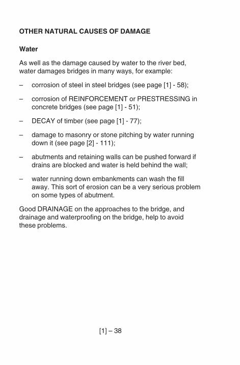
Some of the drainage is easy to see, such as drains on thedeck.
The next picture shows how badly placed deck drains cancause corrosion on a steel girder;
You cannot see drainage behind an abutment, but it isimportant. If water builds up behind an abutment, thepressure of the water may push the abutment forward.
Usually a bridge abutment has a drainage layer behind theabutment wall, and WEEP-HOLES through the front face ofthe abutment wall.
Weep-holes are shown on page [1] - 17.
Sometimes there is also a drain along the bottom of thedrainage layer which collects the water and carries it out tothe side of the abutment.
[1] – 40
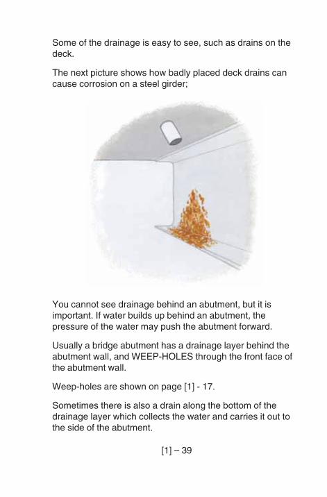
Debris, dirt and vegetation
When dirt or DEBRIS collect on a structure they hold water,and the dampness causes deterioration. If large plants growin these pockets of dirt, their roots can damage the structure:
[1] – 41
If debris carried by the river collects against a pier orabutment, it can block the waterway. The river may thenwash out the road embankment.
If large amounts of debris collect against a pier or the bridgesuperstructure, the force of the water on the debris can badlydamage the bridge.
For many bridges, only part of the waterway is covered bythe river for most of the time. Vegetation grows in the areasthe river does not use. Grasses and light vegetation (such asrice) are good, as they hold the soil in place. Trees, largebushes and large plants (such as bananas) are bad, as theywill block the waterway.
In desert areas, wind-blown sand can block culverts andbridges over dry river beds. When the river flows, the sandmay be washed away but the bridge or culvert might bebadly damaged.
[1] – 42
Earthquakes
Bridges are sometimes damaged by earthquakes. There are2 common types of damage caused by earthquakes.
– foundation failure causing movements of the abutment orpiers;
– the superstructure moving off its supports. Some bridgesin earthquake zones have the superstructure held downto stop it falling off.
Landslides
Another danger to bridges is LANDSLIDES. If there is alandslide which blocks the river upstream from a bridge, thewater will build up behind it. After some time, the river maybreak through and wash the bridge away. This does not oftenhappen, but it is always helpful to talk to local people whenyou inspect a bridge. They can tell you about changes in theriver that you might not see from the bridge site.
[1] – 43
BRIDGE MATERIALS
The main materials used in bridges are concrete, steel,masonry and timber.
This section describes the problems to look for in eachmaterial. In the steel notes, you will also see notes aboutpaint and GALVANISING.
At the end, you will find notes on gabions.
CONCRETE
There are 5 main problems with concrete on bridges:
– cracking of the concrete;
– SPALLING of concrete;
– corrosion of reinforcement or prestressing steel;
– poor quality concrete;
– chemical attack;
These notes on concrete start with some general infor-mation about concrete in bridges. Then they tell you abouteach of these 5 problems.
[1] – 44
General
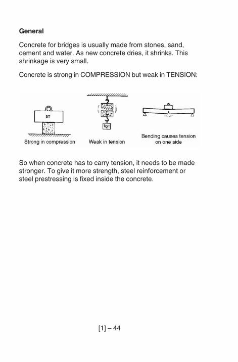
Concrete for bridges is usually made from stones, sand,cement and water. As new concrete dries, it shrinks. Thisshrinkage is very small.
Concrete is strong in COMPRESSION but weak in TENSION:
So when concrete has to carry tension, it needs to be madestronger. To give it more strength, steel reinforcement orsteel prestressing is fixed inside the concrete.
[1] – 45
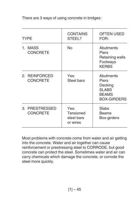
There are 3 ways of using concrete in bridges:
Most problems with concrete come from water and air gettinginto the concrete. Water and air together can causereinforcement or prestressing steel to CORRODE, but goodconcrete can protect the steel. Sometimes water and air cancarry chemicals which damage the concrete, or corrode thesteel more quickly.
CONTAINS OFTEN USEDTYPE STEEL? FOR:
1. MASS No AbutmentsCONCRETE Piers
Retaining wallsFootwaysKERBS
2. REINFORCED Yes: AbutmentsCONCRETE Steel bars Piers
DeckingSLABSBEAMSBOX-GIRDERS
3. PRESTRESSED Yes: SlabsCONCRETE Tensioned Beams
steel bars Box-girdersor wires
[1] – 46
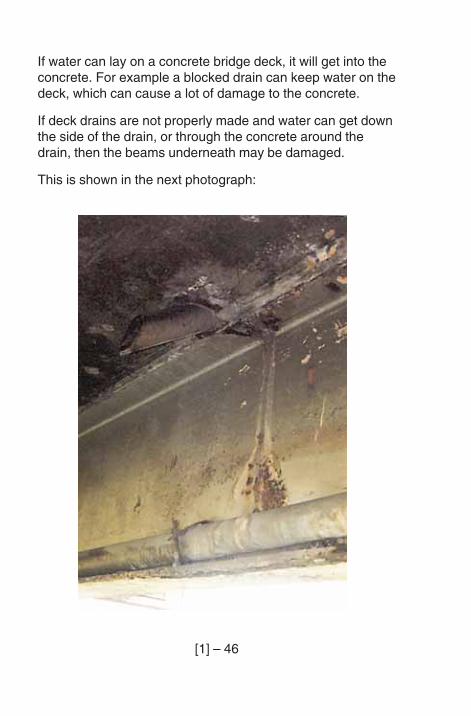
If water can lay on a concrete bridge deck, it will get into theconcrete. For example a blocked drain can keep water on thedeck, which can cause a lot of damage to the concrete.
If deck drains are not properly made and water can get downthe side of the drain, or through the concrete around thedrain, then the beams underneath may be damaged.
This is shown in the next photograph:
[1] – 47
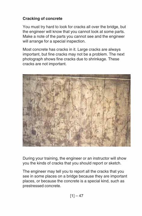
Cracking of concrete
You must try hard to look for cracks all over the bridge, butthe engineer will know that you cannot look at some parts.Make a note of the parts you cannot see and the engineerwill arrange for a special inspection.
Most concrete has cracks in it. Large cracks are alwaysimportant, but fine cracks may not be a problem. The nextphotograph shows fine cracks due to shrinkage. Thesecracks are not important.
During your training, the engineer or an instructor will showyou the kinds of cracks that you should report or sketch.
The engineer may tell you to report all the cracks that yousee in some places on a bridge because they are importantplaces, or because the concrete is a special kind, such asprestressed concrete.
[1] – 48
To report on cracks, look carefully at them and follow thisguide:
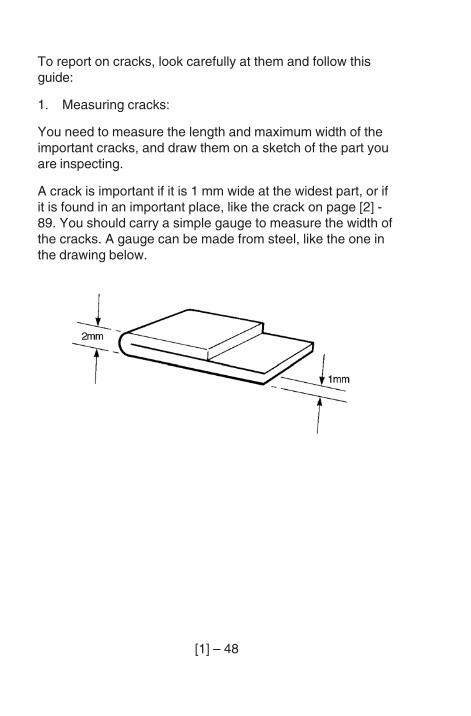
1. Measuring cracks:
You need to measure the length and maximum width of theimportant cracks, and draw them on a sketch of the part youare inspecting.
A crack is important if it is 1 mm wide at the widest part, or ifit is found in an important place, like the crack on page [2] -89. You should carry a simple gauge to measure the width ofthe cracks. A gauge can be made from steel, like the one inthe drawing below.
[1] – 49
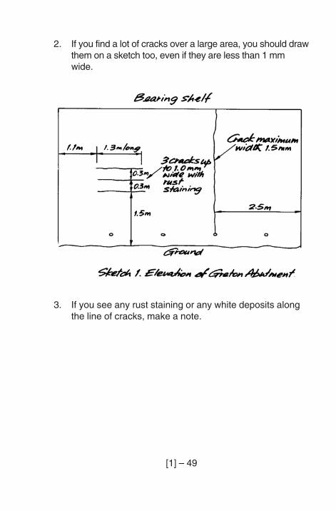
2. If you find a lot of cracks over a large area, you should drawthem on a sketch too, even if they are less than 1 mmwide.
3. If you see any rust staining or any white deposits alongthe line of cracks, make a note.
[1] – 50
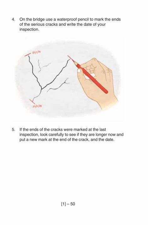
4. On the bridge use a waterproof pencil to mark the endsof the serious cracks and write the date of yourinspection.
5. If the ends of the cracks were marked at the lastinspection, look carefully to see if they are longer now andput a new mark at the end of the crack, and the date.
[1] – 51
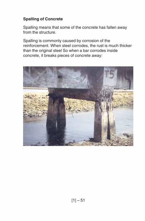
Spalling of Concrete
Spalling means that some of the concrete has fallen awayfrom the structure.
Spalling is commonly caused by corrosion of thereinforcement. When steel corrodes, the rust is much thickerthan the original steel So when a bar corrodes insideconcrete, it breaks pieces of concrete away:
[1] – 52
Corrosion of Reinforcement or Prestressing
This is the most important problem with concrete bridges.This can cause the bridge to fail.
Corrosion can be caused by:
– not enough concrete around the reinforcement;
– a break in the concrete due to serious cracking, spallingor HONEYCOMBING (see the ‘Poor quality concretesection on page [1] - 53);
– poor quality concrete.
Corrosion will happen more quickly when the concrete is in,or near, salt water.
Signs that the reinforcement may be corroding are:
– you can see the reinforcement at the surface of theconcrete;
– you can see cracks or rust stains along a line where youthink there is reinforcement;
– you can see areas where concrete has spalled. Where theconcrete has spalled, you should measure two things:
1. Measure the original COVER to the bars. To do this, puta straight-edge across the spalled area, so you can seewhere the concrete surface was before, and thenmeasure from the straight edge to the nearest part of thereinforcement.
2. Make an estimate of how much of the bar is corrodedaway.
[1] – 53
If you find signs of corrosion, draw a sketch which showswhere the corrosion is. When possible, show the reinforcingbars on your sketch.
Poor quality concrete
There are 3 problems to look for with poor quality concrete:
– water and air can go through the concrete too easily;
– you can see large holes in the surface of the concrete.These holes are called honeycombing;
– chemicals, which you cannot see, in the stream or rivermay damage the concrete.
It is not easy to know if the concrete is poor without specialtests. But if water can get into the top surface of a deck, youmay see dampness on the bottom of the bridge deck. Thiscan mean that the concrete is poor or that the drainage isbad. Whatever the cause, the water should be stopped. If thewater is not stopped, the deck reinforcement will corrodevery soon.
Honeycombing is caused during construction when the wetconcrete does not flow properly and air gets trapped in it.The concrete then has holes where the air was trapped. Ifthere is honeycombing, then the concrete cover to thereinforcement will be much thinner than it should be, and thereinforcement may corrode quickly.
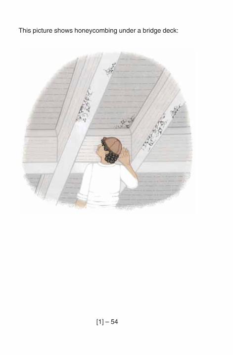
[1] – 54
This picture shows honeycombing under a bridge deck:
[1] – 55
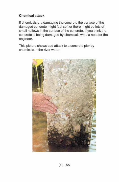
Chemical attack
If chemicals are damaging the concrete the surface of thedamaged concrete might feel soft or there might be lots ofsmall hollows in the surface of the concrete. If you think theconcrete is being damaged by chemicals write a note for theengineer.
This picture shows bad attack to a concrete pier bychemicals in the river water:
[1] – 56
STEEL
Steel bridges need to be inspected for 5 main problems:
– deterioration of paint or galvanising;
– corrosion;
– damage (bends) to steel parts;
– loose fixings;
– cracking.
Deterioration of paint and galvanising
Steel will corrode if it is not protected from air and water.Steel can be protected from corrosion by paint orgalvanising. Sometimes, when the risk of corrosion is high,steel is first galvanised and then painted.
Galvanising is a thin layer of zinc on the surface of the steel.It is put on the steel by a special process. In air, galvanisingstops the steel from rusting for a longer time than paint. Butin salt water, galvanising soon comes off and the steel startsto rust.
Paint or galvanising does not last for many years. Whenpaint or galvanising deteriorates, the steelwork needs newprotection. Painted steelwork can be painted again, andgalvanised steelwork can be painted with a special zinc-richpaint, or with some other paint made for galvanised steel.Before the steelwork can be painted again, the old paint orgalvanising must be very well cleaned and all rust removed,or the new paint will not last long.
[1] – 57
Paint deteriorates when the steel starts to rust. Often, thefirst signs of failure are small spots of rust in the paintsurface. These spots of rust allow water to get under the restof the paint. This causes more rust and the paint starts tocome off. Paint deteriorates more quickly where the paint isthin, e.g. at corners or sharp edges in steelwork. Chemicalsin the air (from factories) can also cause paint deteriorationto happen quickly.
Galvanising deteriorates by corrosion of the zinc. If you seewhite spots on the surface of the zinc then it is corroding.
If the paint or galvanising on a steel bridge is not properlyMAINTAINED the steel will rust.
When you see signs of paint or galvanising failure, makecareful notes and sketches. If repairs are carried out quickly,the corrosion can be stopped.
[1] – 58
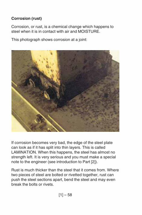
Corrosion (rust)
Corrosion, or rust, is a chemical change which happens tosteel when it is in contact with air and MOISTURE.
This photograph shows corrosion at a joint:
If corrosion becomes very bad, the edge of the steel platecan look as if it has split into thin layers. This is calledLAMINATION. When this happens, the steel has almost nostrength left. It is very serious and you must make a specialnote to the engineer (see introduction to Part [2]).
Rust is much thicker than the steel that it comes from. Wheretwo pieces of steel are bolted or rivetted together, rust canpush the steel sections apart, bend the steel and may evenbreak the bolts or rivets.
[1] – 59
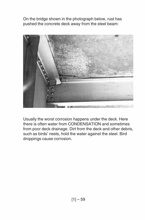
On the bridge shown in the photograph below, rust haspushed the concrete deck away from the steel beam:
Usually the worst corrosion happens under the deck. Herethere is often water from CONDENSATION and sometimesfrom poor deck drainage. Dirt from the deck and other debris,such as birds’ nests, hold the water against the steel. Birddroppings cause corrosion.
[1] – 60
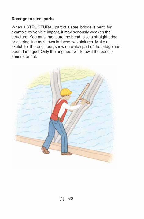
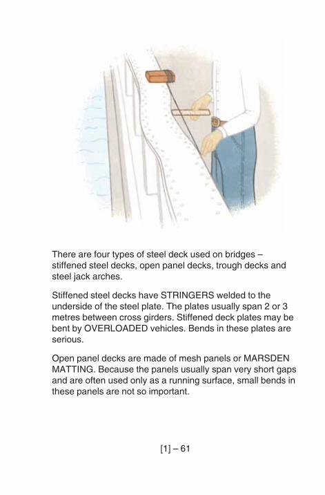
Damage to steel parts
When a STRUCTURAL part of a steel bridge is bent, forexample by vehicle impact, it may seriously weaken thestructure. You must measure the bend. Use a straight edgeor a string line as shown in these two pictures. Make asketch for the engineer, showing which part of the bridge hasbeen damaged. Only the engineer will know if the bend isserious or not.
[1] – 61
There are four types of steel deck used on bridges –stiffened steel decks, open panel decks, trough decks andsteel jack arches.
Stiffened steel decks have STRINGERS welded to theunderside of the steel plate. The plates usually span 2 or 3metres between cross girders. Stiffened deck plates may bebent by OVERLOADED vehicles. Bends in these plates areserious.
Open panel decks are made of mesh panels or MARSDENMATTING. Because the panels usually span very short gapsand are often used only as a running surface, small bends inthese panels are not so important.
[1] – 62
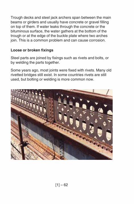
Trough decks and steel jack archers span between the mainbeams or girders and usually have concrete or gravel fillingon top of them. If water leaks through the concrete or thebituminous surface, the water gathers at the bottom of thetrough or at the edge of the buckle plate where two archesjoin. This is a common problem and can cause corrosion.
Loose or broken fixings
Steel parts are joined by fixings such as rivets and bolts, orby welding the parts together.
Some years ago, most joints were fixed with rivets. Many oldrivetted bridges still exist. In some countries rivets are stillused, but bolting or welding is more common now.
[1] – 63
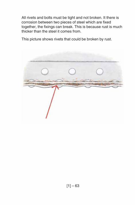
All rivets and bolts must be tight and not broken. It there iscorrosion between two pieces of steel which are fixedtogether, the fixings can break. This is because rust is muchthicker than the steel it comes from.
This picture shows rivets that could be broken by rust.
[1] – 64
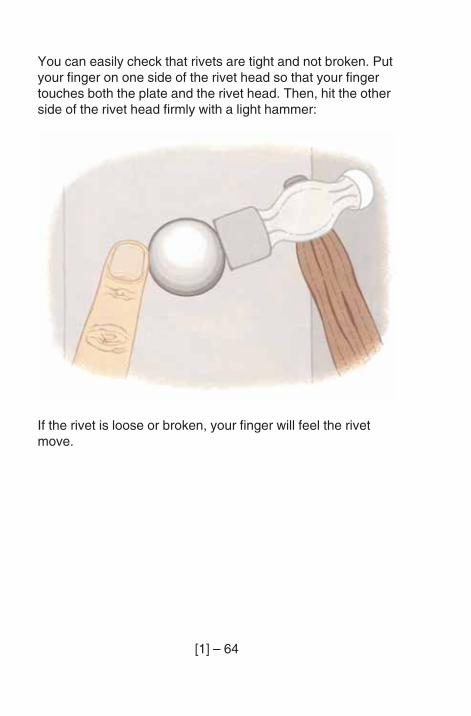
You can easily check that rivets are tight and not broken. Putyour finger on one side of the rivet head so that your fingertouches both the plate and the rivet head. Then, hit the otherside of the rivet head firmly with a light hammer:
If the rivet is loose or broken, your finger will feel the rivetmove.
[1] – 65
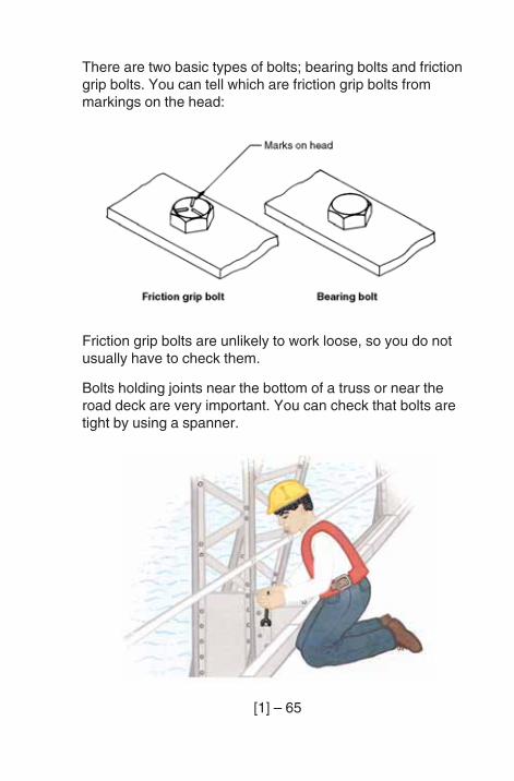
There are two basic types of bolts; bearing bolts and frictiongrip bolts. You can tell which are friction grip bolts frommarkings on the head:
Friction grip bolts are unlikely to work loose, so you do notusually have to check them.
Bolts holding joints near the bottom of a truss or near theroad deck are very important. You can check that bolts aretight by using a spanner.
[1] – 66
You will not have to check every bolt or rivet on a bridge atevery Inspection. The engineer will tell you which joints youmust check at each inspection. An example of a joint whichshould always be checked is where the cross-girders meetthe trusses on a half-through truss.
Cracking of steel
Sometimes, but not often, steel members crack. This can becaused by many heavy loads crossing the bridge, or byproblems with welds, or by faults in the steel.
Look carefully near all welds, holes etc. This is where crackscan start.
If you think you can see a crack, make a sketch for theengineer, showing the crack and where it is on the bridge. Itmay only be a crack in the paint, but it should be checked. Acrack often has a thin line of rust along it.
[1] – 67
MASONRY
There are 4 main problems you may find with masonry:
– cracking;
– bulging;
– poor POINTING;
– deterioration of the bricks or stones.
General
Masonry is bricks or stones with sand and cement mortar inthe joints between them. It is strong in compression andweak in tension, like mass concrete.
Masonry is used for constructing abutments, piers and retainingwalls. Because it has no steel reinforcement, it is not easilydamaged by dampness. Well-maintained masonry structurescarrying light vehicles, have lasted hundreds of years. Butheavy vehicles can damage masonry by VIBRATION ofmasonry arches, or by impact to masonry parapets.
Cracking
Cracking is an important sign that something might be wrongwith masonry. Cracking can be caused by overloading,vibration or impact from traffic, by failure of the foundation, orby temperature changes or wetting and drying.
Cracking weakens masonry, allows water to run through andallows soil to enter the structure After a short time, plants andeven small trees can start to grow in the cracks. As theplants get bigger, they may make the cracks bigger.

[1] – 68
When you see cracks, it is not always easy to know howthey happened. All masonry, like concrete, expands andcontracts with changes in temperature. Masonry built withsome types of brick will also expand as the bricks get wetand contract as the bricks dry out. Cracks caused bytemperature or moisture changes often run through themortar only. Cracks which go through the bricks or stonesof the masonry are very serious. These cracks probablymean that the foundations have failed or that the masonryhas been overloaded.
In your inspection, note and make a sketch of all large cracks(wider than 5 mm), showing where they are on the bridge; allcracks near the bearings, and all cracks where there is astep caused by cracking in the face of the masonry.
[1] – 69
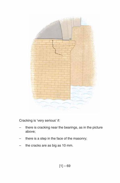
Cracking is ‘very serious’ if:
– there is cracking near the bearings, as in the pictureabove;
– there is a step in the face of the masonry;
– the cracks are as big as 10 mm.
[1] – 70
Bulging
Bulging is a change in shape or bending of the face of amasonry wall, usually due to soil behind pushing part of theface outwards. It can happen to abutments, retaining walls, orthe barrel or spandrel wails of masonry arch bridges. Bulgingof masonry parapets can be caused by vehicle impact.
The force from the soil behind a wall can increase due toextra soil being put on top, or the water level in the soil rising(perhaps due to blocked weep-holes), or compaction andvibration due to heavy vehicles, or shaking by an earthquake.Also, as the mortar pointing becomes old, it may becomeweak, allowing the masonry to bulge.
Make a sketch of any bulges, and measure them with thehelp of a straight edge or string line.
Poor pointing
Pointing is the mortar between the bricks or stones. Themortar can be worn away by the river or by rainwater runningdown the face of the masonry. Pointing is usually weakerthan the stones or bricks and it will deteriorate with age.
If the mortar pointing is worn away or is in poor condition, thebricks or stones may move or even fall out. This weakens thestructure. During inspections, look carefully for poor pointing.
[1] – 71
Deterioration of the bricks or stones
Not all masonry will last a long time. Many types of bricks,and some stones, can be worn away by rain or the river, andby the effects of heating or cooling.
To check if the bricks or stones have deteriorated, tap thesurface (not too hard) with a hammer. If pieces break off, itmay be necessary to protect the surface with a layer of hardmortar, called RENDERING.
[1] – 72
TIMBER
Timber has 2 main problems: decay and insect attack. Noteson the special problems with joints in timber bridges come atthe end of this section on timber.
General
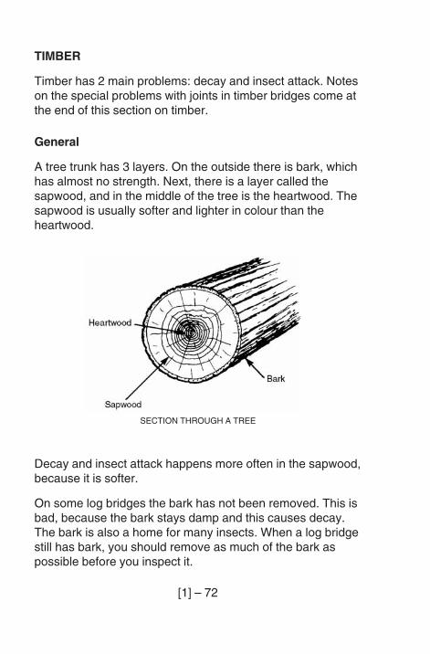
A tree trunk has 3 layers. On the outside there is bark, whichhas almost no strength. Next, there is a layer called thesapwood, and in the middle of the tree is the heartwood. Thesapwood is usually softer and lighter in colour than theheartwood.
Decay and insect attack happens more often in the sapwood,because it is softer.
On some log bridges the bark has not been removed. This isbad, because the bark stays damp and this causes decay.The bark is also a home for many insects. When a log bridgestill has bark, you should remove as much of the bark aspossible before you inspect it.
SECTION THROUGH A TREE
[1] – 73
Decay
Decay is caused by a FUNGUS which attacks damp woodDecay makes the timber go soft and lose its strength.
You should look carefully at those places on the bridge whichare in contact with both water and air.
For example:
– parts in contact with the ground (piles, ends of beams,logs, etc.);
– places where dirt, debris and water collect andvegetation grows (bridge deck and joints in a truss);
– around fixings. Water can sometimes get to the middle ofthe timber through holes for fixings. It will be difficult tosee this type of decay;
– around splits in the timber. Splits are common and willonly lead to decay if water can stay in them, as in splitsin the top of horizontal timbers.
[1] – 74
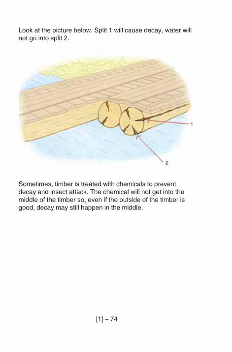
Look at the picture below. Split 1 will cause decay, water willnot go into split 2.
Sometimes, timber is treated with chemicals to preventdecay and insect attack. The chemical will not get into themiddle of the timber so, even if the outside of the timber isgood, decay may still happen in the middle.
[1] – 75
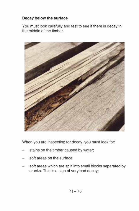
Decay below the surface
You must look carefully and test to see if there is decay inthe middle of the timber.
When you are inspecting for decay, you must look for:
– stains on the timber caused by water;
– soft areas on the surface;
– soft areas which are split into small blocks separated bycracks. This is a sign of very bad decay;
[1] – 76
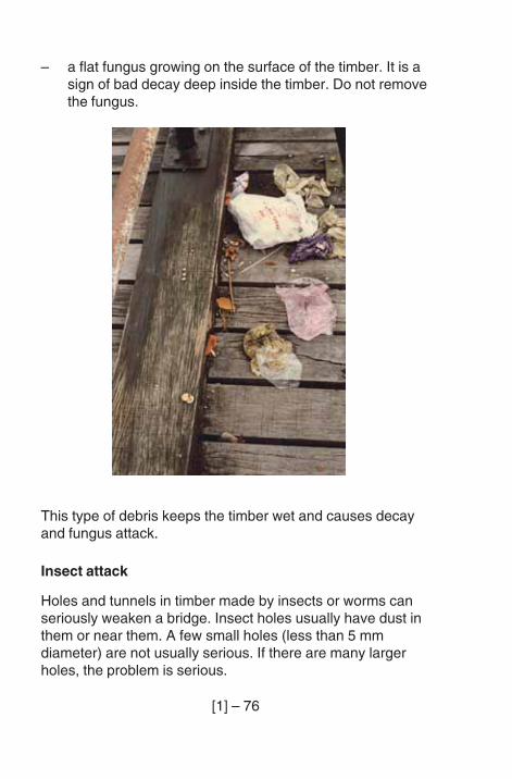
– a flat fungus growing on the surface of the timber. It is asign of bad decay deep inside the timber. Do not removethe fungus.
This type of debris keeps the timber wet and causes decayand fungus attack.
Insect attack
Holes and tunnels in timber made by insects or worms canseriously weaken a bridge. Insect holes usually have dust inthem or near them. A few small holes (less than 5 mmdiameter) are not usually serious. If there are many largerholes, the problem is serious.
[1] – 77
A number of insects attack timber. The most damaging areforest longhorn beetles, which make large holes, andtermites, which make large tunnels through the timber. If yousee termite nests near a timber bridge you will know there isa danger of attack to the bridge.
In salt water, a worm called the teredo can attack any areabelow the high tide level. Teredo worms make large holes andcan cause very serious damage. You must check all piers andpiles in salt water. To test timber in salt water, use theHammer Test (see below). Hit the timber just above the water.
Tests for decay and insect attack
There are 3 simple tests for decay and insect attack:
– Spike Test: To test the surface layer of the timber, pusha spike into the wood to find soft spots. Use a squarespike so the next inspector does not think your spikeholes were caused by insects.
– Hammer Test: To test for decay or insect attack insidethe timber, hit the timber with a hammer. Decayingtimber sounds different from solid timber.
– Drill Test: If you think there is decay inside the timber,drill a small hole into the wood. The different feel ofdrilling into soft wood will tell you if there is decay. Becareful not to make too many holes near joints. The pinor bolt holes at joints are already the weakest part of thetimber. A 5 mm drill is big enough for this test.
[1] – 78
After using the spike or drill test, put some creosote, or otherpreserving chemical, into the hole. Fill drill holes with woodplugs.
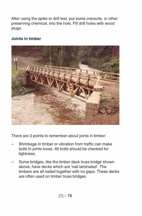
Joints in timber
There are 3 points to remember about joints in timber:
– Shrinkage in timber or vibration from traffic can makebolts in joints loose. All bolts should be checked fortightness.
– Some bridges, like the timber deck truss bridge shownabove, have decks which are ‘nail laminated’. Thetimbers are all nailed together with no gaps. These decksare often used on timber truss bridges.
[1] – 79
For some bridges with nail laminated decks, the connectionbetween the deck and the truss is very important for thestrength of the bridge. This connection must be checkedfrom below, to see that the deck is tightly nailed to the topmember of the truss.
– The joints in timber are often made with steel plates,bolts and pins. These steel parts must also be checked.You should look for loose pins and damaged or corrodedbolts, pins or plates.
[1] – 80
GABIONS
Gabions are wire baskets filled with stones.
Most gabion baskets are 2 metres x 1 metre x 1 metre insize. For scour protection a thinner, larger gabion issometimes used. This is called a reno mattress. Renomattresses are usually not more than 0.5 metres thick.
The baskets can be tied together with wire to form retainingwalls. Gabion retaining walls can bulge without damage tothe gabions.
Baskets can be tied together to form mattresses to coverlarge areas of slopes or river beds. Gabion mattresses canchange shape a lot without damage. This makes themspecially useful for protecting abutments, piers and roadembankments against scour. As the river scours, the gabionssettle into a new position, but still protect the abutment pier orembankment.
For simple bridges, gabion baskets can be tied together tomake an abutment. If the gabions change shape, this maynot damage the gabion abutment, but any SETTLEMENT ofthe abutment can damage the deck.
[1] – 81
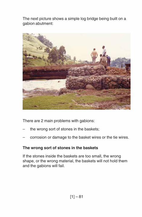
There are 2 main problems with gabions:
– the wrong sort of stones in the baskets;
– corrosion or damage to the basket wires or the tie wires.
The wrong sort of stones in the baskets
If the stones inside the baskets are too small, the wrongshape, or the wrong material, the baskets will not hold themand the gabions will fail.
The next picture shows a simple log bridge being built on agabion abutment:
[1] – 82
Corrosion or damage to basket wires or tie wires
Basket wires and tie wires are galvanised or coated withplastic, but they will corrode after some time. If they corrodebadly, they may break. Basket wire and tie wires can alsobreak if the gabions change shape too much. Wires and tiescan also be broken by debris in the river.
If the wires and ties break, the stones may be washed away.However, plants may grow in soil between the stones andhelp to keep stones in place, even when the wires havecorroded.
[1] – 83
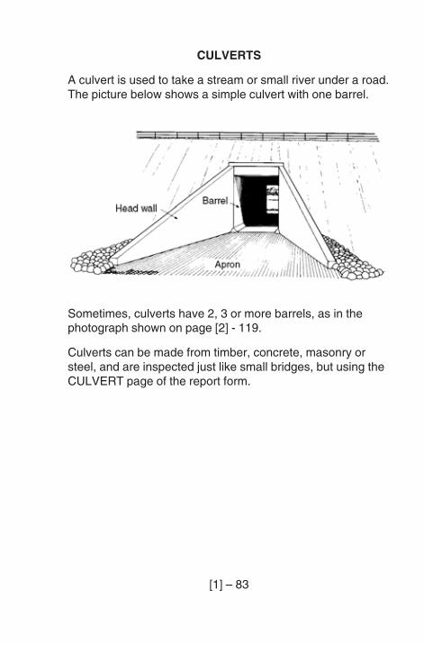
CULVERTS
A culvert is used to take a stream or small river under a road.The picture below shows a simple culvert with one barrel.
Sometimes, culverts have 2, 3 or more barrels, as in thephotograph shown on page [2] - 119.
Culverts can be made from timber, concrete, masonry orsteel, and are inspected just like small bridges, but using theCULVERT page of the report form.
[1] – 84
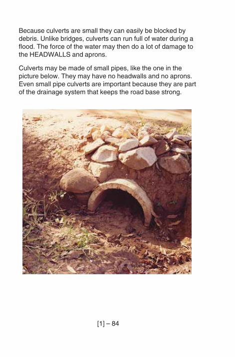
Because culverts are small they can easily be blocked bydebris. Unlike bridges, culverts can run full of water during aflood. The force of the water may then do a lot of damage tothe HEADWALLS and aprons.
Culverts may be made of small pipes, like the one in thepicture below. They may have no headwalls and no aprons.Even small pipe culverts are important because they are partof the drainage system that keeps the road base strong.
[2] – 1
PART (2) – THE INSPECTION
INTRODUCTION
Now that you have read and you understand Part [1] of thisbook, you are ready to inspect bridges. For each inspectionyou will use a report form. Your first inspections should bewith an engineer, so that you can ask questions and learnhow to use the report form.
BEFORE YOU GO
Before you go, look at a copy of the bridge record card forthe bridge you will inspect and the last inspection report form,if there is one.
The bridge record card has details of the bridge you are toinspect: where it is, how long it is, and what type of bridge itis. It will also have a drawing or photograph to help you knowit when you get there. Some details on the bridge record cardmust be written on the report form before you leave theoffice. These are listed on page 2 of the form. You will checkthat they are right when you get to the bridge.
The last report form will tell you what problems were foundduring the last inspection. You should look carefully to see ifthese problems have got worse. The notes and sketches willhelp you to measure the problems.
You should check in the office to find out if any maintenancehas been done on the bridge since the last inspection. Youshould look on the bridge or in the river to see if themaintenance has been done well, and to see if it has solvedthe problem.

[2] – 2
There may be other notes in the office that be useful to you.For example, there may be a report of an earthquake or aflood in the area of the bridge, or a complaint from driversthat some damage has been done. You should make a noteand remember these things when you make the inspection.
Before you go, make sure that you have all the equipmentthat you will need. Appendix B has a list that you can use.Change the list to suit the way you work and use it each timebefore you go.
[2] – 3
THE INSPECTION
The following notes follow the order of the inspection reportform in Appendix D at the end of this book.
Appendix D is a completed report form to show you how afinished form will be. Look at it to see how an inspectorshould work, but remember that you must fill in your reportform to show what you have seen. The ticks you make maybe in different boxes to the ticks shown in Appendix D.
Report form page 1:
Arriving at the bridge
It is easy to make a mistake and inspect the wrong bridge.
CHECK that you are at the right bridge:
!!!!! Check the bridge number.
!!!!! Check the bridge name.
!!!!! Check the distance from the beginning of the road,or use the kilometre posts.
These three things to check are at the top of page 1 of thereport form.
* * *
Read carefully the INSTRUCTIONS FROM THE ENGINEERTO THE INSPECTOR.
* * *
[2] – 4
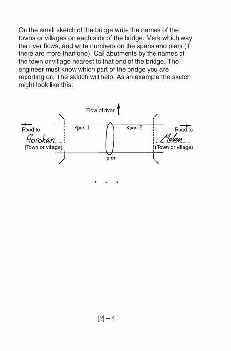
On the small sketch of the bridge write the names of thetowns or villages on each side of the bridge. Mark which waythe river flows, and write numbers on the spans and piers (ifthere are more than one). Call abutments by the names ofthe town or village nearest to that end of the bridge. Theengineer must know which part of the bridge you arereporting on. The sketch will help. As an example the sketchmight look like this:
* * *
[2] – 5
At the end of the inspection
When you have finished inspecting the bridge, look carefullyat your report:
– Have you filled in all the sections?
– Have you made all the notes and sketches that you needto?
– Have you numbered all your notes and sketches?
– Have you written these numbers in the correct place onthe form?
– Will the engineer be able to understand?
– Are there any problems not on the form, which youshould tell the engineer about by writing a note?
When you are sure you have finished, sign the report form atthe bottom of page 1. Also write the date of the inspection andthe number of pages in your report. Make sure that the pages,including any notes and sketches, are fixed together. Thentake it back to the office for the attention of the engineer.
* * *
[2] – 6
Report from page 2:
Construction details, Services and Signs
CONSTRUCTION DETAILS
CHECK each construction detail as well as you can andtick it as CORRECT: YES or NO.
* * *
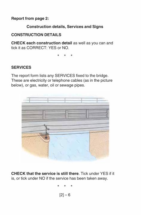
SERVICES
The report form lists any SERVICES fixed to the bridge.These are electricity or telephone cables (as in the picturebelow), or gas, water, oil or sewage pipes.
CHECK that the service is still there. Tick under YES if itis, or tick under NO if the service has been taken away.
* * *
[2] – 7
Check for new services. If you find any new services thatare not written on the form, write a note to say what newservices are there and say if they cause a problem.
CHECK for damage to services. If there is a problem make anote on the form, especially if it can damage the bridge. Forexample a leak from a waterpipe can cause deterioration.
Write a note if you can see damage to the bridge by theService Authority.
SIGNS
Signs are very important. They may give limits on height,width, weight and speed. The bridge can be badly damagedand may fall if a vehicle hits part of it or if a very heavyvehicle overloads it. Drivers must be able to read the signs.
Page 2 of the report form has a list of all the signs whichshould be on or near the bridge.
CHECK that each of the signs is still there. Tick underYES if the sign is still there or tick under NO if you cannotfind it.
CHECK for damage to the signs. Make sure each sign isstill fixed firmly and that it can still be read by drivers. Make anote of any damage on the report form.
Make a note if you find any signs that are not written on theform.
[2] – 8
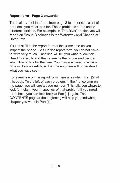
Report form - Page 3 onwards
The main part of the form, from page 3 to the end, is a list ofproblems you must look for. These problems come underdifferent sections. For example, in ‘The River’ section you willreport on Scour, Blockages in the Waterway and Change ofRiver Path.
You must fill in the report form at the same time as youinspect the bridge. To fill in the report form, you do not haveto write very much. Each line will tell you what to look for.Read it carefully and then examine the bridge and decidewhich box to tick for that line. You may also need to write anote or draw a sketch, so that the engineer will understandwhat you have seen.
For every line on the report form there is a note in Part [2] ofthis book. To the left of each problem, in the first column onthe page, you will see a page number. This tells you where tolook for help in your inspection of that problem. If you needmore help, you can look back at Part [1] again. TheCONTENTS page at the beginning will help you find whichchapter you want in Part [1].
[2] – 9
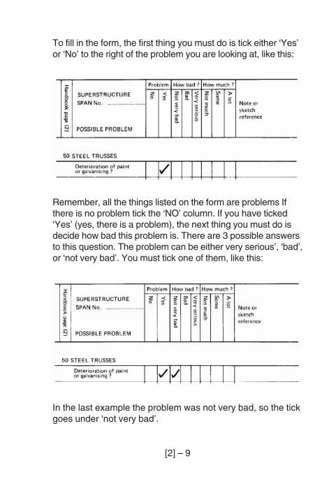
To fill in the form, the first thing you must do is tick either ‘Yes’or ‘No’ to the right of the problem you are looking at, like this:
Remember, all the things listed on the form are problems Ifthere is no problem tick the ‘NO’ column. If you have ticked‘Yes’ (yes, there is a problem), the next thing you must do isdecide how bad this problem is. There are 3 possible answersto this question. The problem can be either very serious’, ‘bad’,or ‘not very bad’. You must tick one of them, like this:
In the last example the problem was not very bad, so the tickgoes under ‘not very bad’.
[2] – 10
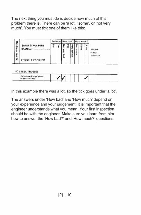
The next thing you must do is decide how much of thisproblem there is. There can be ‘a lot’, ‘some’, or ‘not verymuch’. You must tick one of them like this:
In this example there was a lot, so the tick goes under ‘a lot’.
The answers under ‘How bad’ and ‘How much’ depend onyour experience and your judgement. It is important that theengineer understands what you mean. Your first inspectionshould be with the engineer. Make sure you learn from himhow to answer the ‘How bad?’ and ‘How much?’ questions.
[2] – 11
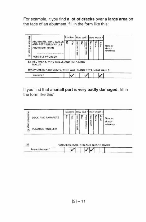
For example, it you find a lot of cracks over a large area onthe face of an abutment, fill in the form like this:
If you find that a small part is very badly damaged, fill inthe form like this’
[2] – 12
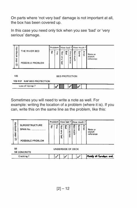
On parts where ‘not very bad’ damage is not important at all,the box has been covered up.
In this case you need only tick when you see ‘bad’ or ‘veryserious’ damage.
Sometimes you will need to write a note as well. Forexample: writing the location of a problem (where it is). If youcan, write this on the same line as the problem, like this:
[2] – 13
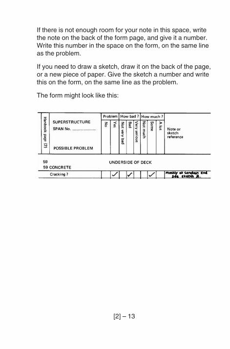
If there is not enough room for your note in this space, writethe note on the back of the form page, and give it a number.Write this number in the space on the form, on the same lineas the problem.
If you need to draw a sketch, draw it on the back of the page,or a new piece of paper. Give the sketch a number and writethis on the form, on the same line as the problem.
The form might look like this:
[2] – 14
Take your time and fill in each line of the report form carefullyas you come to it. Remember that you must fill in the format the time you are looking at the problem. Do not waituntil later.
Sometimes it is very difficult to know the answers, evenexperienced inspectors may not be able to tell. If you do notknow how bad or how much, or if you are not sure if there isa problem, make a note.
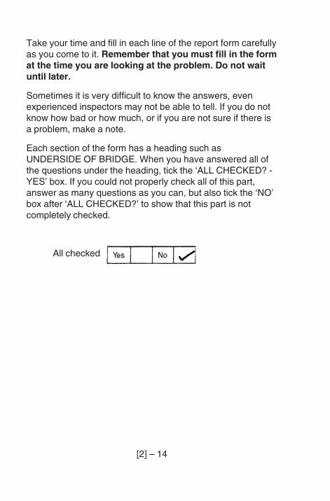
Each section of the form has a heading such asUNDERSIDE OF BRIDGE. When you have answered all ofthe questions under the heading, tick the ‘ALL CHECKED? -YES’ box. If you could not properly check all of this part,answer as many questions as you can, but also tick the ‘NO’box after ‘ALL CHECKED?’ to show that this part is notcompletely checked.
All checked
[2] – 15
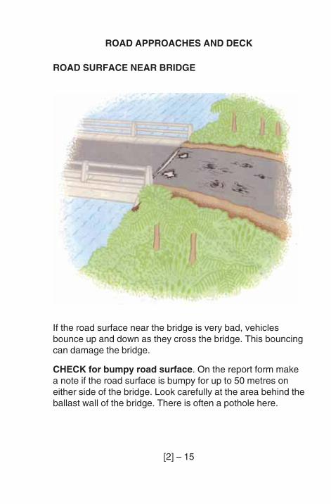
ROAD APPROACHES AND DECK
ROAD SURFACE NEAR BRIDGE
If the road surface near the bridge is very bad, vehiclesbounce up and down as they cross the bridge. This bouncingcan damage the bridge.
CHECK for bumpy road surface. On the report form makea note if the road surface is bumpy for up to 50 metres oneither side of the bridge. Look carefully at the area behind theballast wall of the bridge. There is often a pothole here.
[2] – 16
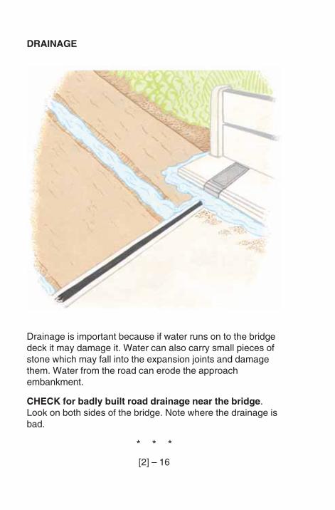
DRAINAGE
Drainage is important because if water runs on to the bridgedeck it may damage it. Water can also carry small pieces ofstone which may fall into the expansion joints and damagethem. Water from the road can erode the approachembankment.
CHECK for badly built road drainage near the bridge.Look on both sides of the bridge. Note where the drainage isbad.
* * *
[2] – 17
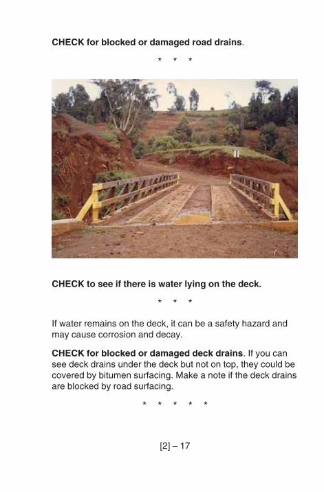
CHECK for blocked or damaged road drains.
* * *
CHECK to see if there is water lying on the deck.
* * *
If water remains on the deck, it can be a safety hazard andmay cause corrosion and decay.
CHECK for blocked or damaged deck drains. If you cansee deck drains under the deck but not on top, they could becovered by bitumen surfacing. Make a note if the deck drainsare blocked by road surfacing.
* * * * *
[2] – 18
BRIDGE SURFACE & FOOTPATHS
The road surface on the bridge can be sealed with bitumen,or made of concrete, steel or timber. There is a differentsection of the report form for each surface.
If the footpath is the same surface as the road, report on theroad and footpath together. If the footpath is a differentsurface from the road surface, then report on the roadsurface and footpath surface separately. Note on the formwhich is the footpath.
BITUMEN SURFACE
At deck joints where very small movements are expected,the surfacing may cover over the joint. Often the sealedsurface cracks or breaks-up over these joints. Surfacing isoften damaged at joints.
* * *
CHECK if the surface is breaking-up or lifting off theconcrete underneath. Look very carefully near theexpansion joints and near the drain holes.
* * *
[2] – 19
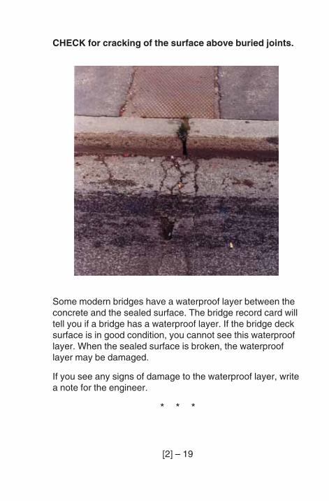
CHECK for cracking of the surface above buried joints.
Some modern bridges have a waterproof layer between theconcrete and the sealed surface. The bridge record card willtell you if a bridge has a waterproof layer. If the bridge decksurface is in good condition, you cannot see this waterprooflayer. When the sealed surface is broken, the waterprooflayer may be damaged.
If you see any signs of damage to the waterproof layer, writea note for the engineer.
* * *
[2] – 20
CONCRETE SURFACE
CHECK for cracking of the concrete. Look again at thenotes on page [1] - 47 if you are not sure how to do this.
On long span truss bridges look carefully for cracking of theconcrete decks. Any cracks which begin in spalled areas ofthe deck are serious.
* * *
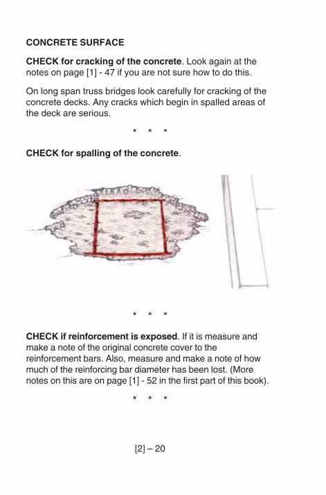
CHECK for spalling of the concrete.
* * *
CHECK if reinforcement is exposed. If it is measure andmake a note of the original concrete cover to thereinforcement bars. Also, measure and make a note of howmuch of the reinforcing bar diameter has been lost. (Morenotes on this are on page [1] - 52 in the first part of this book).
* * *
[2] – 21
Check for poor quality concrete. Look for honey-combingand other signs of poor quality concrete.
* * *
If the road to the bridge is not surfaced with bitumen, smallstones in vehicle tyres can damage the surface of theconcrete.
CHECK for wear of the surface due to small stones intyres.
* * *
[2] – 22
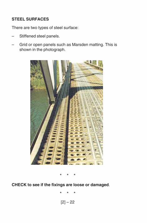
STEEL SURFACES
There are two types of steel surface:
– Stiffened steel panels.
– Grid or open panels such as Marsden matting. This isshown in the photograph.
* * *
CHECK to see if the fixings are loose or damaged.
* * *
[2] – 23
CHECK for bends in the steel panels. For Marsdenmatting, only make a note of bad bends. On other decks noteall bends.
* * *
CHECK for corrosion of the steel surface. Look carefullyat areas near kerbs and deck drains.
* * *
[2] – 24
TIMBER SURFACE
Dirt, debris and plants in corners and between the boardshold water in the timber. This will damage the deck.
CHECK for dirt or plants growing between the boards.Look carefully close to kerbs or running strips.
* * *
CHECK for decay of the deck timber. Look carefully nearthe deck ends and against kerbs and running strips.
* * *
Check for signs of insect attack. Look at all parts of thetimber deck.
* * *
CHECK for splitting of timbers. For deck timbers, smallsplits are not important, but larger splits should be reported.
* * *
Loose deck timbers are very dangerous on any bridge andcould cause an accident.
On some bridges, the deck timber helps to strengthen thewhole bridge. On these bridges it is very important that thedeck fixings are good. The engineer will tell you if you areinspecting this kind of bridge.
CHECK for loose or damaged fixings.
* * *
[2] – 25
TIMBER RUNNING STRIPS
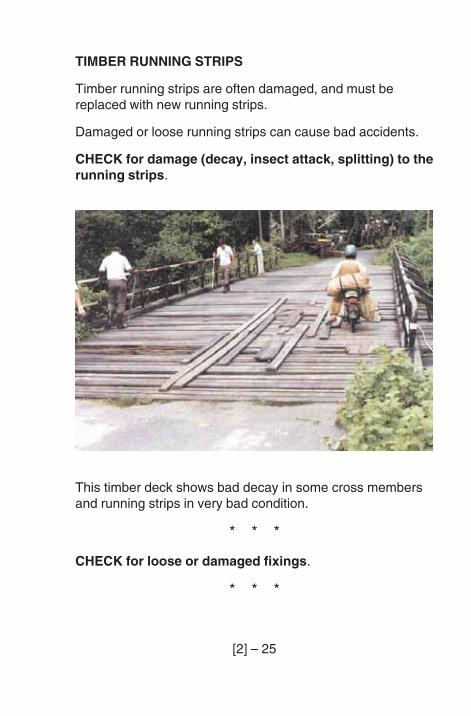
Timber running strips are often damaged, and must bereplaced with new running strips.
Damaged or loose running strips can cause bad accidents.
CHECK for damage (decay, insect attack, splitting) to therunning strips.
This timber deck shows bad decay in some cross membersand running strips in very bad condition.
* * *
CHECK for loose or damaged fixings.
* * *
[2] – 26
RAILWAY OR TRAM RAILS
Rail or tram tracks sometimes cross road bridges. The railscan work loose, especially near expansion joints. If thishappens, the bridge deck can be badly damaged as the trainor tram bounces over the loose rail.
CHECK for loose rail fixings.
* * *
KERBS
Kerbs separate the road from the footpath. They are often hitby vehicles.
On some bridges high kerbs are used to stop vehicles drivingonto the footpath. These high kerbs are sometimes usedinstead of guard rails.
CHECK for damaged or loose kerbs.
* * *
FOOTPATHS
Damaged paving slabs or boards can be a danger for peoplewalking across the bridge.
CHECK for damaged footpaths.
* * * * *
[2] – 27
PARAPETS, RAILINGS AND GUARD RAILS
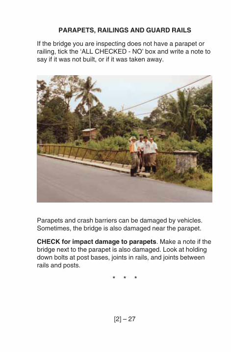
If the bridge you are inspecting does not have a parapet orrailing, tick the ‘ALL CHECKED - NO’ box and write a note tosay if it was not built, or if it was taken away.
Parapets and crash barriers can be damaged by vehicles.Sometimes, the bridge is also damaged near the parapet.
CHECK for impact damage to parapets. Make a note if thebridge next to the parapet is also damaged. Look at holdingdown bolts at post bases, joints in rails, and joints betweenrails and posts.
* * *
[2] – 28
CHECK for loose or damaged fixings.
* * *
CHECK for loose post bases where steel, aluminium ortimber parapets are set in holes in concrete.
* * *
The next sections are about parapets made of particularmaterials.
Sometimes, parapets are made of two materials. For example,if there are concrete posts with steel rails, report on the postsusing the concrete section and the rails in the steel section.
STEEL or ALUMINIUM PARAPETS
CHECK for damaged galvanising or paint.
* * *
CHECK for corrosion.
* * *
[2] – 29
CONCRETE PARAPETS
CHECK for cracking.
* * *
CHECK for spalling of the concrete. Look carefully at thecorners of the posts and rails.
* * *
CHECK for corrosion of reinforcement. Look whereconcrete has spalled. Look for rust stains from cracks,especially near the corners of the posts and rails.
* * *
CHECK for poor concrete.
* * *
[2] – 30
TIMBER PARAPETS
CHECK for decay, especially at the base of the posts and atjoints between posts and rails.
* * *
CHECK for insect attack.
* * *
CHECK for splitting of timber.
* * *
[2] – 31
MASONRY PARAPETS
Masonry, whether brick or stone, damages easily if vehicleshit it. Often it cracks and may be pushed outwards.
Small cracks in masonry are not usually important.
CHECK for serious cracking.
* * *
CHECK for outward movement or bending of theparapet.
* * *
CHECK for poor pointing.
* * *
CHECK for deterioration of the bricks or stonework ofthe parapet.
* * * * *
[2] – 32
EXPANSION JOINTS
There are many different sorts of expansion joints that canbe used on bridges. It is a good idea to check the bridgerecord card in the office, before going out to the bridge, tofind out what sort of joint is used and where the joints are onthe bridge.
If you look at the bridge record card, you must also lookcarefully for other joints on the bridge. The bridge record cardcould be wrong.
The next five checks can be done from above, as you standon the deck, but remember the joints when you go under thedeck. Look for signs of problems and listen when vehiclespass over the bridge. You might hear the sound of looseplates or see signs of damage.
[2] – 33
CHECK for damage to the concrete of the deck end orballast wall near to the joint.
* * *
Joints on long bridges sometimes have several moving parts.Stones or other debris can stop some of the parts frommoving.
CHECK for debris or vegetation in the joints.
* * *
CHECK for loose or damaged fixings. With steel parts, thisis a common problem.
* * *
CHECK for damage or corrosion to metal parts of thejoint.
* * *
Some joints have a rubber water-bar to stop water and debrisfrom the deck falling through the joint. Stones falling into thejoint can cut the water bar.
CHECK for damage to the rubber water-bars.
* * * * *
[2] – 34
THE RIVER
You must look very carefully for changes in the river. You willbe able to see most problems from the deck of the bridge orstanding under it by the abutments. Sometimes you mayhave to walk along the banks for a short distance to checkwhat is happening to the river.
BLOCKAGES IN THE WATERWAY
The waterway under a bridge should be clear. Any blockageis bad because:
1. it can make the water scour a hole in the river bed; and
2. debris can get stuck on it and make a bigger blockage.
CHECK that debris carried by a flood has not piled upagainst piers or abutments blocking the waterway.
* * *
[2] – 35
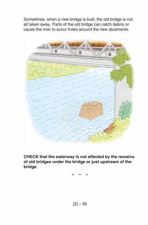
Sometimes, when a new bridge is built, the old bridge is notall taken away. Parts of the old bridge can catch debris orcause the river to scour holes around the new abutments.
CHECK that the waterway is not affected by the remainsof old bridges under the bridge or just upstream of thebridge.
* * *
[2] – 36
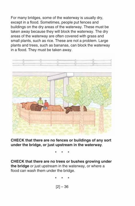
For many bridges, some of the waterway is usually dry,except in a flood. Sometimes, people put fences andbuildings on the dry areas of the waterway. These must betaken away because they will block the waterway. The dryareas of the waterway are often covered with grass andsmall plants, such as rice. These are not a problem. Largeplants and trees, such as bananas, can block the waterwayin a flood. They must be taken away.
CHECK that there are no fences or buildings of any sortunder the bridge, or just upstream in the waterway.
* * *
CHECK that there are no trees or bushes growing underthe bridge or just upstream in the waterway, or where aflood can wash them under the bridge.
* * *
[2] – 37
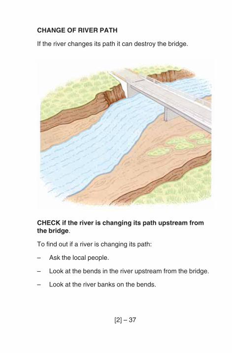
CHANGE OF RIVER PATH
If the river changes its path it can destroy the bridge.
CHECK if the river is changing its path upstream fromthe bridge.
To find out if a river is changing its path:
– Ask the local people.
– Look at the bends in the river upstream from the bridge.
– Look at the river banks on the bends.
[2] – 38
Usually you can see far enough upstream from the bridge.Sometimes you may need to go upstream a short distance.
If the bank is steep and there are trees at the edge of thebank, but nothing is growing on the bank, then the river ismoving towards that bank. When there is a lot of waterflowing and the bank is not steep and has small plantsgrowing on it and some mud or small stones on it, then theriver is moving away from that bank.
* * *
You must also look for other changes upstream of the bridge.If new islands form, then the river may change its path andmay damage the bridge.
CHECK to see if new islands are forming. Look to see ifthere is debris in the river. Debris can cause a new island toform.
* * *
[2] – 39
RIVER TRAINING WORKS
Two things can go wrong with river training works.
– The river can move beyond the upstream end of the rivertraining works and attack the end of the works.
– The materials of the works may be damaged.
CHECK for river attack beyond the upstream end of theriver training works.
* * *
Piles may move forward with scour or be damaged by floatinglogs. Timber piles may decay, steel piles may corrode.
CHECK for damage to sheet piled walls.
* * *
Rip-rap can sink into a soft river bed, or be washed away.
CHECK for loss of rip-rap.
* * *
Groynes made of gabions, or fencing can be washed awayor damaged.
CHECK for damage to gabions, timber fencing, etc.
* * *
[2] – 40
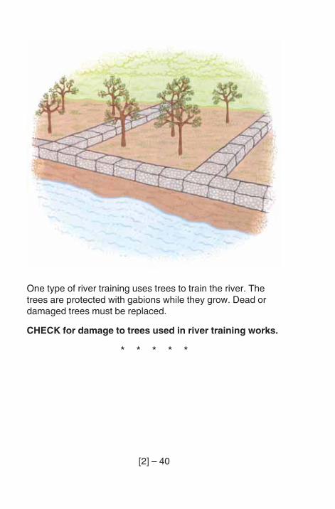
One type of river training uses trees to train the river. Thetrees are protected with gabions while they grow. Dead ordamaged trees must be replaced.
CHECK for damage to trees used in river training works.
* * * * *
[2] – 41
SUPERSTRUCTURE
The report form asks you to look at some general problemsof bridge superstructures first. You then look at the mainsupports (beams, slab, girders or trusses), whether they areabove or below the deck. Sometimes, to inspect a bridgeproperly, you will have to look at the same part of the bridge(such as a truss) from above the road and below the road.
Finally, you look at the problems under the bridge deck.
You must repeat this inspection and fill in a new part of thereport form for each span.
[2] – 42
GENERAL
Bridges are often damaged by vehicles hitting the girders ortrusses. Even small bends in girders and trusses can beserious. Sometimes, during a flood, a boat, log or otherfloating debris hits a bridge and damages it.
CHECK for impact damage to beams, girders, trusses orbracings by vehicles, boats or logs. Make a note of how youthink the damage was caused.
* * *
CHECK for debris or vegetation on beams, girders,trusses, bracings or in joints. These can cause seriousdamage to the bridge.
* * *
If the underside of the bridge deck is wet, this can damagethe bridge.
CHECK that there is no water coming through the bridgedeck, except through proper drains.
If the underside is not wet, there may still be a problem. Youneed to look for signs that the underside has been wet before:
– On steelwork, look for rusty marks.
– On timber, look for dark water run marks.
– On concrete, look for dark areas and a build up of whitematerial on the surface.
* * *
[2] – 43
CHECK that water from the deck drainage does not flowon to the girders, trusses, beams or bracings.
* * *
For a bridge which carries a road over another road, it isimportant that there is enough headroom.
When a road is resurfaced, too much bituminous surfacing maybe put on, so that the headroom to an overbridge is too small. Ifthe road has been resurfaced since the last inspection:
CHECK for enough headroom for an overbridge
Measure the headroom where it is smallest, from the surfaceof the road below to the underside of the bridgesuperstructure. Write the headroom in the box on the form.
* * * * *
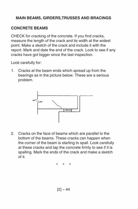
[2] – 44
MAIN BEAMS, GIRDERS,TRUSSES AND BRACINGS
CONCRETE BEAMS
CHECK for cracking of the concrete. If you find cracks,measure the length of the crack and its width at the widestpoint. Make a sketch of the crack and include it with thereport. Mark and date the end of the crack. Look to see if anycracks have got bigger since the last inspection.
Look carefully for:
1. Cracks at the beam ends which spread up from thebearings as in the picture below. These are a seriousproblem.
2. Cracks on the face of beams which are parallel to thebottom of the beams. These cracks can happen whenthe corner of the beam is starting to spall. Look carefullyat these cracks and tap the concrete firmly to see if it isspalling. Mark the ends of the crack and make a sketchof it.
* * *
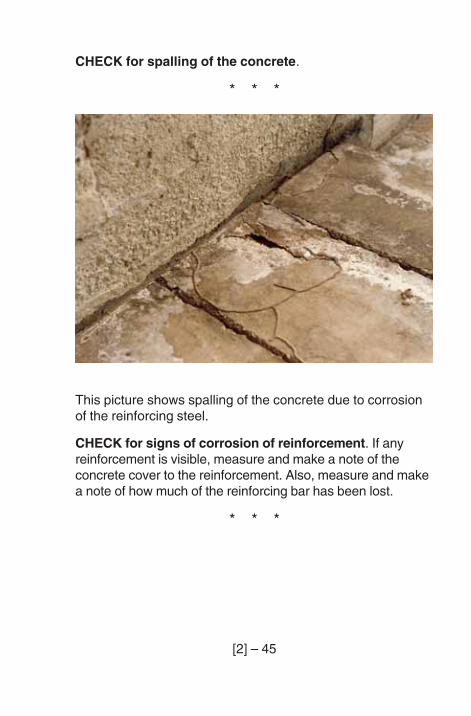
[2] – 45
CHECK for spalling of the concrete.
* * *
This picture shows spalling of the concrete due to corrosionof the reinforcing steel.
CHECK for signs of corrosion of reinforcement. If anyreinforcement is visible, measure and make a note of theconcrete cover to the reinforcement. Also, measure and makea note of how much of the reinforcing bar has been lost.
* * *
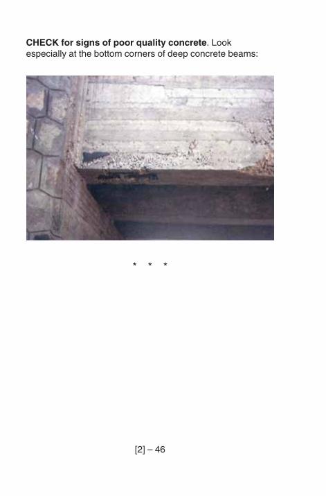
[2] – 46
CHECK for signs of poor quality concrete. Lookespecially at the bottom corners of deep concrete beams:
* * *
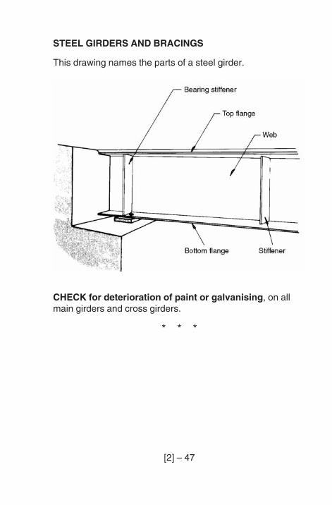
[2] – 47
STEEL GIRDERS AND BRACINGS
This drawing names the parts of a steel girder.
CHECK for deterioration of paint or galvanising, on allmain girders and cross girders.
* * *
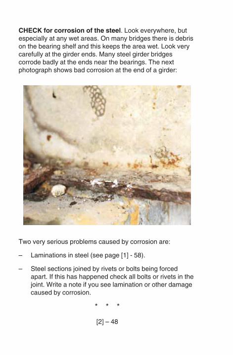
[2] – 48
CHECK for corrosion of the steel. Look everywhere, butespecially at any wet areas. On many bridges there is debrison the bearing shelf and this keeps the area wet. Look verycarefully at the girder ends. Many steel girder bridgescorrode badly at the ends near the bearings. The nextphotograph shows bad corrosion at the end of a girder:
Two very serious problems caused by corrosion are:
– Laminations in steel (see page [1] - 58).
– Steel sections joined by rivets or bolts being forcedapart. If this has happened check all bolts or rivets in thejoint. Write a note if you see lamination or other damagecaused by corrosion.
* * *
[2] – 49
A big overload can cause a bend along most of the girder. Youcan see these bends by looking along the edge of the girderflange. Bends in the beams or girders are serious. Also lookfor bends in the STIFFENERS above the bearings. Make asketch of the damage and show which part is damaged.
CHECK for bends in webs and flanges of girders, and instiffeners and bracings.
If possible, measure the size of all bends. Place a straightedge or string line next to the damaged member andmeasure from this to the girder.
* * *
CHECK for loose bolts or rivets. On the structure mark allloose bolts or rivets with a waterproof pencil or paint. Make asketch of the girders and mark the joints which have loosebolts or rivets.
* * *
CHECK for cracking, especially at welds and holes. If you findany cracking write a note to say where the cracking is on thegirder and draw a sketch. Cracking can be very dangerous.
* * *
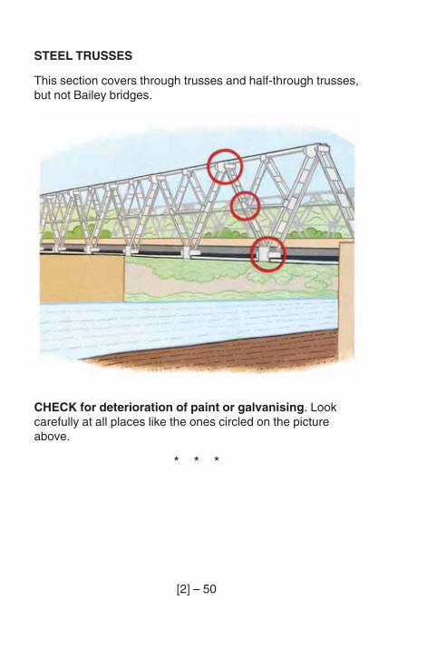
[2] – 50
STEEL TRUSSES
This section covers through trusses and half-through trusses,but not Bailey bridges.
CHECK for deterioration of paint or galvanising. Lookcarefully at all places like the ones circled on the pictureabove.
* * *
[2] – 51
CHECK for corrosion, especially at the joints in the truss.The bottom boom joints often corrode first. If there are signsof corrosion, especially near joints, check that plates are notlaminated (see page [1] - 58).
Look for signs that corrosion is forcing the plates apart.
* * *
CHECK for bends in truss members. Make a sketch of thetruss and mark any bent members on it. Using a straightedge or string line, measure the size of the bend and mark iton the sketch.
* * *
CHECK for bent or damaged joints. Make a sketch of thetruss and mark any damaged joints on it.
* * *
CHECK for bent or damaged bracings. Measure the bendif possible and make a careful sketch of the pattern of thebracing system. Mark the damaged member on your sketch.
* * *
[2] – 52
CHECK for loose bolts or rivets. Check all bolts or rivets indamaged or corroded joints. On the structure mark all loosebolts or rivets with paint. On a sketch of the truss, mark thejoints with loose fixings.
If you find loose, damaged or missing bolts or rivets in a joint,look carefully along the line of the truss to see if the top hasbent. If you see that it has bent, measure the bend with a lineas shown in the pictures on page [2] - 81 and write a note.
* * *
Cracking is very serious as it can lead to rapid collapse. Theengineer will tell you which areas must be checked for eachinspection.
CHECK for cracking of the steel, particularly at welds andholes. If you find cracking, write a note or sketch to showwhere the crack is.
* * *
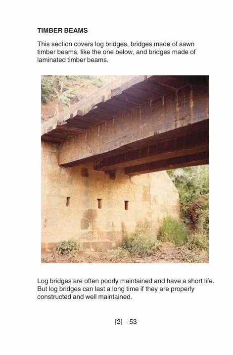
[2] – 53
TIMBER BEAMS
This section covers log bridges, bridges made of sawntimber beams, like the one below, and bridges made oflaminated timber beams.
Log bridges are often poorly maintained and have a short life.But log bridges can last a long time if they are properlyconstructed and well maintained.
[2] – 54
CHECK all timber for decay. Look very carefully at dampareas and around nails or spikes.
If the bridge beams (or logs) sit on the soil, or if the beamsends come into contact with the soil, then the ends oftendecay. Check this area carefully.
Look very carefully at logs with bark still in place, and whenpossible remove the bark.
* * *
CHECK all timbers for insect attack. If insect attack ordecay is found, find out how much of the timber is affected.The notes on page [1] - 77 tell you about three tests using aspike, a hammer or a drill. Using one or more of these tests,keep checking until you find good timber. Make a sketch ofthe beam or log showing the decay or insect attack. Note onthe sketch the size of the bad area and the depth.
* * *
CHECK for splitting of timber. There are 2 kinds of splitwhich are important. Make a note if you find either of these:
1. Very large splits which may be getting bigger.
2. A split which will allow water to get into the beam or logand not drain out.
Splits on the top, or on the upper part of the sides, of a beamor log, are a problem. Splits on the bottom of a beam, or on avertical member will drain and are not a problem.
* * *
[2] – 55
Sometimes beams are made by sticking together smallerpieces of timber. These are called glue laminated beams. Ifthe glue fails, the laminations (the small pieces which makeup the beam) may separate. This could be serious.
CHECK for separation of the laminations of gluelaminated beams.
On beam bridges, the main beams are often connected bytimber cross beams which are nailed or spiked to the mainbeams. The nails or spikes should be tight.
On long span log bridges, sometimes many logs are neededThese are often held together by wire ropes. Check that theropes are not corroded and are tightly fastened.
CHECK for loose or corroded nails, spikes or fixingwires.
* * *
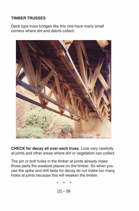
[2] – 56
TIMBER TRUSSES
Deck type truss bridges like this one have many smallcorners where dirt and debris collect:
CHECK for decay all over each truss. Look very carefullyat joints and other areas where dirt or vegetation can collect.
The pin or bolt holes in the timber at joints already makethose parts the weakest places on the timber. So when youuse the spike and drill tests for decay do not make too manyholes at joints because this will weaken the timber.
* * *
[2] – 57
CHECK for insect attack.
* * *
CHECK for splitting of timber.
Some splits can be serious. There are 2 kinds of split youmust report:
– large splits at joints which are close to bolt or pin holes. Ifyou find these, make a sketch of the split, show thelength of the split and the distance to any holes. This willhelp the next inspector to see if there is a problem. If thelast inspector noted a split near a joint, check to see if ithas got worse;
– splits where the wood is wet, causing decay inside thewood.
* * *
CHECK to see if the deck to truss connection is loose.This is very important on bridges with nail laminated decks.
* * *
CHECK for loose or corroded bolts or pins at the trussjoints. As timber dries, it shrinks. This can cause bolts injoints to be loose. Bolts can also loosen because of vibration.
* * *
[2] – 58
CHECK for bends in truss members. Make a sketch of thetruss and mark any bent members on it. Measure the size ofthe bend and mark it on the sketch. On bridges with thetrusses above the road, look along the line of the truss to seeif the top has bent. Measure the bend and make a note.
Small bends can be measured in the way shown on pages[1] - 60 and [1] – 61. Long bends in a truss are measured inthe way shown on page [2] - 81.
* * *
CHECK for damaged or corroded steel parts (joint plates,bearing plates, etc.), and mark their location on a sketch.
* * * * *
[2] – 59
UNDERSIDE OF DECK
CONCRETE
CHECK for cracking of concrete. Make sketches of anycracks wider than 1 mm, or cracks over a wide area. Markand date the ends of important cracks, note any whitedeposits, and check if cracks have got any bigger since thelast inspection.
* * *
CHECK for spalling of concrete.
* * *
CHECK for corrosion of reinforcement. Note any ruststaining. Where concrete has spalled, note the cover andhow much of the original bar has been lost by corrosion.Make a sketch to show where you have found signs ofcorrosion of reinforcement. Mark on it the size of areas ofspalling, the pattern of cracking or the pattern of rust staining.
* * *
CHECK for poor concrete. Make a sketch showing thelocation and size of honeycombed areas and areas whichare damp.
* * *
CHECK for not enough cover to reinforcement. If thecover is very small, you can see the pattern of reinforcementon the surface of the concrete.
* * *
[2] – 60
STEEL
This section is for the underside of stiffened steel decks, forsteel arch decks (buckle plates) and for trough decks.
CHECK for deterioration of paint or galvanising.
* * *
CHECK for corrosion of steel. Look everywhere, but checkany wet areas especially. Look carefully at the bottom oftroughs and the edge of steel arch decks. If you findlaminations or other bad corrosion you must write a note onthe form.
* * *
CHECK for bends in stringers or plates. On steel deckedbridges if you notice a bend in the surface, look very carefullyat the underside of the deck, below the bend. The stringerswhich carry the deck may have bent. This is serious.
On steel arch decks bends in the plate of the arches are veryserious.
* * *
CHECK for loose bolts or rivets.
* * *
CHECK for cracking of the steel, especially at welds andholes.
* * *
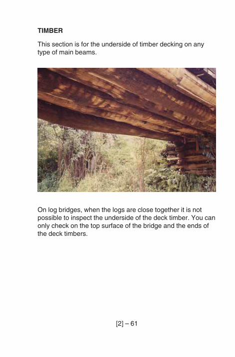
[2] – 61
TIMBER
This section is for the underside of timber decking on anytype of main beams.
On log bridges, when the logs are close together it is notpossible to inspect the underside of the deck timber. You canonly check on the top surface of the bridge and the ends ofthe deck timbers.
[2] – 62
CHECK for decay, look especially at any areas where waterfrom the deck flows onto the timber.
Remember to seal and plug any drill holes you make.
If the timber deck is on a steel bridge look at the placeswhere the timber sits on the steel beams. Also look for decaywhere the bolts or spikes enter the timber.
* * *
CHECK for insect attack.
* * *
CHECK for split timbers. When you inspected the topsurface you will have seen any splits which go through thedeck timbers.
Splits across the grain of the wood, which can be seen onthe underside but not on the top surface, can happen whenthe timber is starting to break, possibly because of a heavyvehicle. If this has happened, make a note in your report thatthe timber must be replaced.
* * *
CHECK for loose or badly corroded bolts or pins.
* * *
[2] – 63
MASONRY JACK ARCH DECKS
CHECK for change of shape of the arch. This can happenbecause of an overload or a failure in the material of the arch.If the change of shape is serious, the arch must be rebuilt.
* * *
CHECK for cracking or spalling of the bricks or masonry.
* * *
CHECK for poor pointing of the arches. If the mortarbetween the bricks or stones is in poor condition the archesmight need repointing.
* * * * *
[2] – 64
BEARINGS
This section covers all types of bridge except Bailey bridges.
Sometimes you will not be able to see all the parts of abearing. If you cannot check all of a bearing, tick the ‘ALLCHECKED - NO’ box and do not tick the ‘YES’ or ‘NO’ boxnext to the questions you cannot answer.
First find out which bearings are fixed, and which are free.The bridge record card will give you the location of the fixedand free bearings. If you have difficulty, look back at pages[1] -21 to [1] -23.
Bearing shelves are very often wet places in which debrisand vegetation collect.
CHECK for debris or vegetation around the bearings andon the bearing shelf. Remember, even small amounts ofdebris on the bearing shelf may cause damage to thebearing, especially if the drainage to the bearing shelf is notworking properly.
* * *
CHECK for poor drainage to the bearing shelf. Look forsigns that water stays on the shelf in wet weather.
* * *
[2] – 65
CHECK to see if there is not enough room for the bridgespan to move when the temperature changes. This is noteasy. Tick ‘YES’ or ‘NO’ only if you are sure.
* * *
CHECK to see if the bearings are not seated properly onthe abutment.
* * *
CHECK to see if the bridge span is not seated properlyon the bearings.
* * *
CHECK for damaged bedding mortar. Look for cracksaround the edges, and look for pieces of mortar which arebroken off or crushed. You will need to clean all the soil andplants away from the bearing to see this.
* * *
[2] – 66
RUBBER BEARINGS
Some rubber bearings have steel plates inside. If you cansee the steel inside the rubber, the fault is bad.
CHECK for splitting, tearing or cracking of the rubber.
* * *
Fixed bearings usually have a pin or bolt fixing the beam tothe support through the bearing. On concrete bridges, it isnot possible to see the pins used in the fixed bearings. Theycannot, therefore, be checked. On steel girder bridges theheads of the bolts or pins can usually be inspected.
CHECK for damaged or loose bolts or pins at fixedbearings on steel beam bridges.
* * *
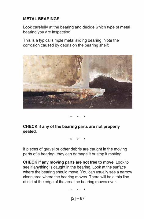
[2] – 67
METAL BEARINGS
Look carefully at the bearing and decide which type of metalbearing you are inspecting.
This is a typical simple metal sliding bearing. Note thecorrosion caused by debris on the bearing shelf:
* * *
CHECK if any of the bearing parts are not properlyseated.
* * *
If pieces of gravel or other debris are caught in the movingparts of a bearing, they can damage it or stop it moving.
CHECK if any moving parts are not free to move. Look tosee if anything is caught in the bearing. Look at the surfacewhere the bearing should move. You can usually see a narrowclean area where the bearing moves. There will be a thin lineof dirt at the edge of the area the bearing moves over.
* * *
[2] – 68
Some rocker or roller type bearings, and bearings wheresteel slides on bronze, have LUBRICATION SYSTEMS.
CHECK for problems with the lubrication system. If thereis a lubrication system and you find a fault with it, write a noteon the form.
* * *
For a sliding bearing to work, the sliding surfaces must be ingood condition.
CHECK to see if the sliding surfaces are damaged. Lookvery carefully at the sliding surfaces. A small amount ofcorrosion on a sliding surface will cause large forces. Thebridge could then be damaged. Look carefully at the PTFEbut be careful. It is easily damaged.
* * *
CHECK for cracks or bends in metal parts.
* * *
CHECK for corrosion of metal parts.
* * *
[2] – 69
EARTHQUAKE RESTRAINTS
On modern bridges in earthquake areas, there may be anearthquake restraint. An earthquake restraint stops the spanfrom falling off the abutment or pier during an earthquake.
There are many types of earthquake restraint. Here are fourcommon types:
1. A large bolt or bolts which hold the span down.
2. Extra strong wing walls which stop the span falling off.
3. A block of concrete between the bridge girders.
4. Special frames of steel or concrete, at the end of thebridge, which stop it falling off in an earthquake.
CHECK for damaged or loose earthquake restraints.
* * * * *
[2] – 70
MASONRY ARCHES
CHECK for change of shape of the arch. You must:
1. Stand a long way from the arch. Compare the shape ofthe arch left of centre, with the shape of the arch right ofcentre. Any difference means the arch has changedshape.
2. Look at the centre stone on the face of the arch. If thishas moved out of line, the arch will be badly weakened.
3. Go underneath the arch and check the barrel of the arch.Look to see if parts of the barrel have changed shapedifferently from the face of the arch. (This often happens).
4. Look at the other face to see if the arch has changed itsshape or if the centre stone has moved.
Mark the location of any change of shape on a sketch or onthe overall plan on page 1 of the report form. Estimate theamount of change of shape, if possible, and write it on yourreport.
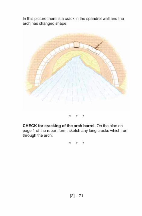
[2] – 71
In this picture there is a crack in the spandrel wall and thearch has changed shape:
* * *
CHECK for cracking of the arch barrel. On the plan onpage 1 of the report form, sketch any long cracks which runthrough the arch.
* * *
[2] – 72
If you find vehicle damage to the parapets, check that thespandrel walls under the parapet have not been pushed outor cracked by the impact.
Where a road crosses an arch bridge there is sometimes ahump. When heavy vehicles hit this, they can push thespandrel walls outwards.
Two things can happen:
1. The spandrel wall can crack and bulge.
2. The spandrel wall separates from the arch and is pushedoutwards. If this happens, you can see a step in themasonry between the arch barrel and the spandrel wall.
CHECK for cracking or bulging of the spandrel walls. Ifyou see a crack or bulge make a sketch of each face of thearch and spandrel walls. Mark any cracks or bulges on yoursketch.
* * *
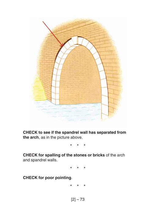
[2] – 73
CHECK to see if the spandrel wall has separated fromthe arch, as in the picture above.
* * *
CHECK for spalling of the stones or bricks of the archand spandrel walls.
* * *
CHECK for poor pointing.
* * *
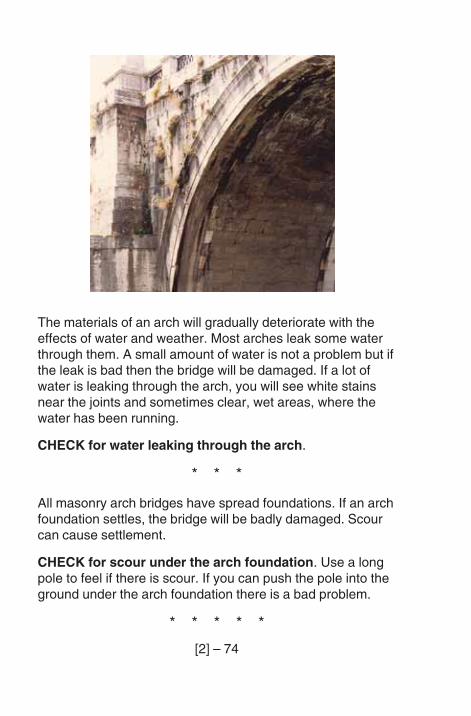
[2] – 74
The materials of an arch will gradually deteriorate with theeffects of water and weather. Most arches leak some waterthrough them. A small amount of water is not a problem but ifthe leak is bad then the bridge will be damaged. If a lot ofwater is leaking through the arch, you will see white stainsnear the joints and sometimes clear, wet areas, where thewater has been running.
CHECK for water leaking through the arch.
* * *
All masonry arch bridges have spread foundations. If an archfoundation settles, the bridge will be badly damaged. Scourcan cause settlement.
CHECK for scour under the arch foundation. Use a longpole to feel if there is scour. If you can push the pole into theground under the arch foundation there is a bad problem.
* * * * *
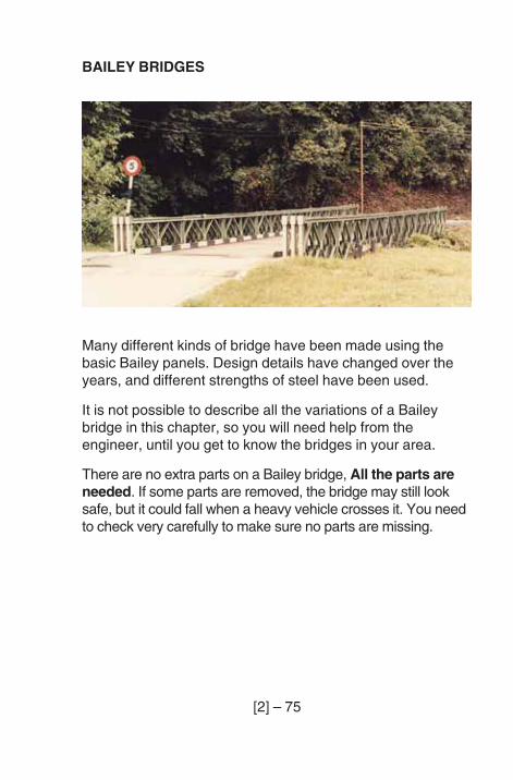
[2] – 75
BAILEY BRIDGES
Many different kinds of bridge have been made using thebasic Bailey panels. Design details have changed over theyears, and different strengths of steel have been used.
It is not possible to describe all the variations of a Baileybridge in this chapter, so you will need help from theengineer, until you get to know the bridges in your area.
There are no extra parts on a Bailey bridge, All the parts areneeded. If some parts are removed, the bridge may still looksafe, but it could fall when a heavy vehicle crosses it. You needto check very carefully to make sure no parts are missing.
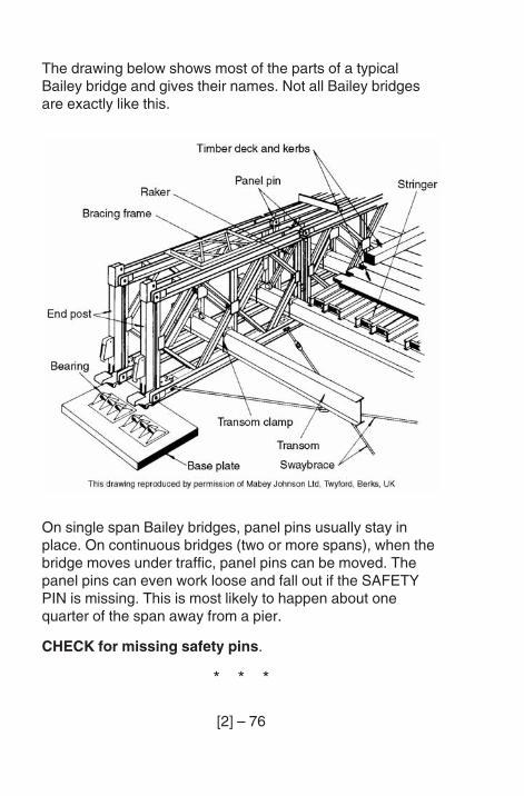
[2] – 76
The drawing below shows most of the parts of a typicalBailey bridge and gives their names. Not all Bailey bridgesare exactly like this.
On single span Bailey bridges, panel pins usually stay inplace. On continuous bridges (two or more spans), when thebridge moves under traffic, panel pins can be moved. Thepanel pins can even work loose and fall out if the SAFETYPIN is missing. This is most likely to happen about onequarter of the span away from a pier.
CHECK for missing safety pins.
* * *
[2] – 77
CHECK for missing panel pins.
* * *
CHECK for missing or loose bolts. The bolts that hold onthe CHORD reinforcement and hold together DOUBLESTOREY BRIDGES are very important.
* * *
CHECK for missing rakers and tie plates. Some bridgesuse vertical bracing frames in place of rakers.
* * *
CHECK for missing or loose sway braces. Check that thepins are in place and that the lock nuts are screwed up.
* * *
Some Bailey bridges have horizontal bracing frames on thetop chords of the panels.
CHECK for missing, loose or damaged horizontalbracing frames.
* * *
CHECK for missing or loose transom clamps. Somemodern Bailey bridges do not use transom clamps. Forthese, note on the inspection form - ‘no transom clamps’.
* * *
Bailey bridges move a lot when vehicles cross them. Thiscauses wear, where the stringers sit on the transoms.
CHECK for wear at the stringer to transom SEATING.
* * *
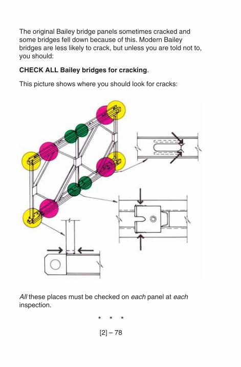
[2] – 78
The original Bailey bridge panels sometimes cracked andsome bridges fell down because of this. Modern Baileybridges are less likely to crack, but unless you are told not to,you should:
CHECK ALL Bailey bridges for cracking.
This picture shows where you should look for cracks:
All these places must be checked on each panel at eachinspection.
* * *
[2] – 79
Parts of the bridge can get bent.
CHECK for bends in bridge members. Note where thedamage is and sketch the damage.
* * *
CHECK for deterioration of paint or galvanising.
* * *
CHECK for corrosion. There are some areas on a Baileybridge where dirt and moisture collect. Look especially at:
1. The bearings.
2. The base of the rakers.
3. The bottom chord near the SPACER PLATES and wherethe diagonal members (diamonds) join.
4. The panels and transoms near where the transom sitson the bottom chord.
Bailey bridges are made of lots of panels, so it is not easy tomake a sketch showing where you have found a problem. Ifyou find a panel that is damaged, or has any problem, mark itwith paint and give it a number. When you fill in the reportform you can write the number in the column for notes.
* * *
CHECK for settlement of the bearings.
* * *
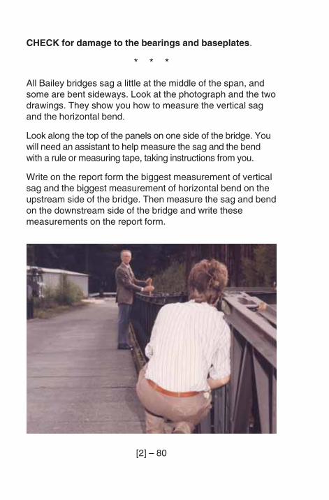
[2] – 80
CHECK for damage to the bearings and baseplates.
* * *
All Bailey bridges sag a little at the middle of the span, andsome are bent sideways. Look at the photograph and the twodrawings. They show you how to measure the vertical sagand the horizontal bend.
Look along the top of the panels on one side of the bridge. Youwill need an assistant to help measure the sag and the bendwith a rule or measuring tape, taking instructions from you.
Write on the report form the biggest measurement of verticalsag and the biggest measurement of horizontal bend on theupstream side of the bridge. Then measure the sag and bendon the downstream side of the bridge and write thesemeasurements on the report form.
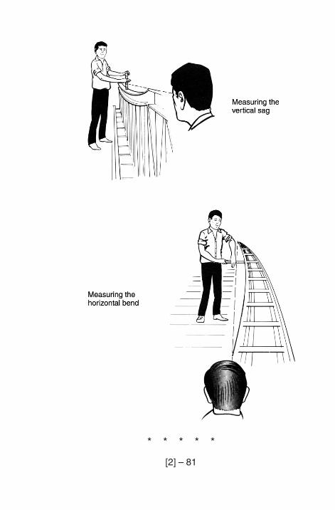
[2] – 81
* * * * *
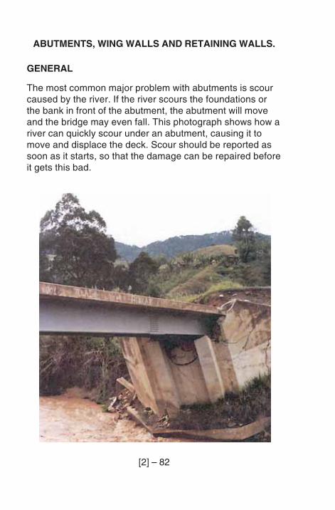
[2] – 82
ABUTMENTS, WING WALLS AND RETAINING WALLS.
GENERAL
The most common major problem with abutments is scourcaused by the river. If the river scours the foundations orthe bank in front of the abutment, the abutment will moveand the bridge may even fall. This photograph shows how ariver can quickly scour under an abutment, causing it tomove and displace the deck. Scour should be reported assoon as it starts, so that the damage can be repaired beforeit gets this bad.
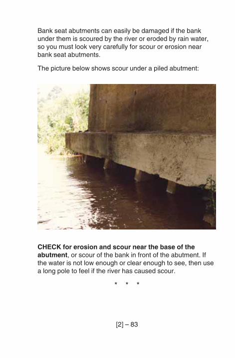
[2] – 83
Bank seat abutments can easily be damaged if the bankunder them is scoured by the river or eroded by rain water,so you must look very carefully for scour or erosion nearbank seat abutments.
The picture below shows scour under a piled abutment:
CHECK for erosion and scour near the base of theabutment, or scour of the bank in front of the abutment. Ifthe water is not low enough or clear enough to see, then usea long pole to feel if the river has caused scour.
* * *
[2] – 84
CHECK for damage to caissons, or damage or corrosionto piles, if you can see them.
* * *
CHECK for movement of the abutment. This can be aserious problem.
Look for disturbance of the ground around the abutment. Ifthe abutment has moved, there are often cracks in the soil.There may even be cracks in the road behind the abutment.
* * *
In a flood, debris against the abutment can cause damage tothe abutment or the bridge superstructure. Debris can alsocause the river to scour the soil around the abutment.
CHECK that there is no debris on, or against, theabutment.
* * *
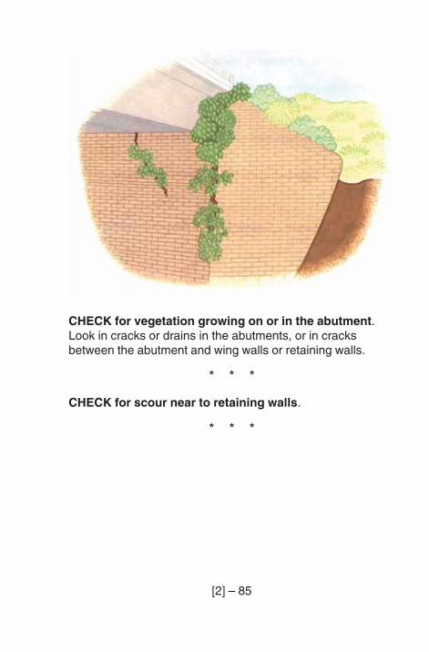
[2] – 85
CHECK for vegetation growing on or in the abutment.Look in cracks or drains in the abutments, or in cracksbetween the abutment and wing walls or retaining walls.
* * *
CHECK for scour near to retaining walls.
* * *
[2] – 86
CHECK for signs of movement (sliding forward orsettlement) of retaining walls.
Look at the picture on page [1] - 30.
Look for:
– a step where the retaining wall meets the wing walls orabutment;
– damage to the road or the embankment supported bywalls.
* * *
CHECK for signs of water leaking down through theexpansion joint.
* * *
[2] – 87
DRAINAGE SYSTEM
Look at the abutment and the retaining walls. Look for signsthat the drainage system is not working properly.
CHECK to see if there are not enough weep-holes. As ageneral guide, weep-holes should be less than 2 metresapart, measured both horizontally and vertically. If the watercoming out of the weep-holes washes away the soil in frontof the abutment then there are not enough weep-holes.
* * *
CHECK to see if the weep-holes are not working. In wetweather, check that the bottom weep-holes have carriedwater recently.
In dry weather, look carefully to find out if the weep-holescarried water when it was raining.
Look for signs such as:
– if there are insect nests in the weep-holes, then theweep-holes may not be working.
– if there are water stains below the weep-holes, then theweep-holes are probably working.
* * *
[2] – 88
Water may find other ways through the abutment if thedrainage system is blocked.
CHECK for water leaking through the abutment. Look fordampness or white staining at cracks or construction joints.
* * *
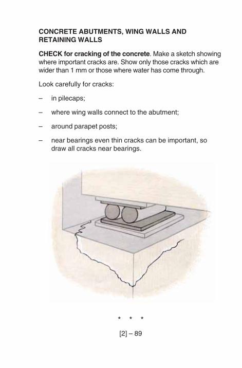
[2] – 89
CONCRETE ABUTMENTS, WING WALLS ANDRETAINING WALLS
CHECK for cracking of the concrete. Make a sketch showingwhere important cracks are. Show only those cracks which arewider than 1 mm or those where water has come through.
Look carefully for cracks:
– in pilecaps;
– where wing walls connect to the abutment;
– around parapet posts;
– near bearings even thin cracks can be important, sodraw all cracks near bearings.
* * *
[2] – 90
CHECK for spalling of the concrete. Mark spalled areas ona sketch.
* * *
CHECK for corrosion of reinforcement. Look for rust stainsfrom cracks and look where concrete has spalled. Whereconcrete has spalled, measure the concrete cover toreinforcement, and measure how much of the bar has been lost.
* * *
CHECK for poor quality concrete. Look for honeycombingand chemical attack.
* * *
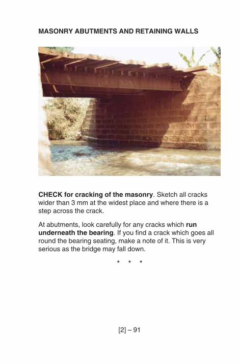
[2] – 91
MASONRY ABUTMENTS AND RETAINING WALLS
CHECK for cracking of the masonry. Sketch all crackswider than 3 mm at the widest place and where there is astep across the crack.
At abutments, look carefully for any cracks which rununderneath the bearing. If you find a crack which goes allround the bearing seating, make a note of it. This is veryserious as the bridge may fall down.
* * *
[2] – 92
Bulges in abutments are more serious than bulges inretaining walls. Any bulge, especially if there are horizontalcracks near it, can be serious.
CHECK for bulging of the abutment or retaining walls. Makea sketch showing the area which is bulging. If you can, put astraight edge against the bulging part and measure howmuch it has moved out of line.
* * *
CHECK for poor pointing of the masonry.
* * *
CHECK for deterioration of the bricks or stones.
* * *
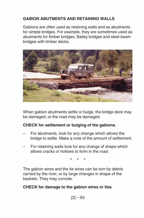
[2] – 93
GABION ABUTMENTS AND RETAINING WALLS
Gabions are often used as retaining walls and as abutmentsfor simple bridges. For example, they are sometimes used asabutments for timber bridges, Bailey bridges and steel beambridges with timber decks.
When gabion abutments settle or bulge, the bridge deck maybe damaged, or the road may be damaged.
CHECK for settlement or bulging of the gabions.
– For abutments, look for any change which allows thebridge to settle. Make a note of the amount of settlement.
– For retaining walls look for any change of shape whichallows cracks or hollows to form in the road.
* * *
The gabion wires and the tie wires can be torn by debriscarried by the river, or by large changes in shape of thebaskets. They may corrode.
CHECK for damage to the gabion wires or ties.
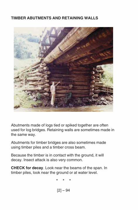
[2] – 94
TIMBER ABUTMENTS AND RETAINING WALLS
Abutments made of logs tied or spiked together are oftenused for log bridges. Retaining walls are sometimes made inthe same way.
Abutments for timber bridges are also sometimes madeusing timber piles and a timber cross beam.
Because the timber is in contact with the ground, it willdecay. Insect attack is also very common.
CHECK for decay. Look near the beams of the span. Intimber piles, look near the ground or at water level.
* * *
[2] – 95
CHECK for insect attack. Look where the beams sit on theabutment.
* * *
CHECK for splitting of timber.
* * *
CHECK for loose or corroded binding cables.
* * *
CHECK for loose or corroded fixing spikes.
* * * * *
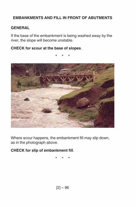
[2] – 96
EMBANKMENTS AND FILL IN FRONT OF ABUTMENTS
GENERAL
If the base of the embankment is being washed away by theriver, the slope will become unstable.
CHECK for scour at the base of slopes.
* * *
Where scour happens, the embankment fill may slip down,as in the photograph above.
CHECK for slip of embankment fill.
* * *
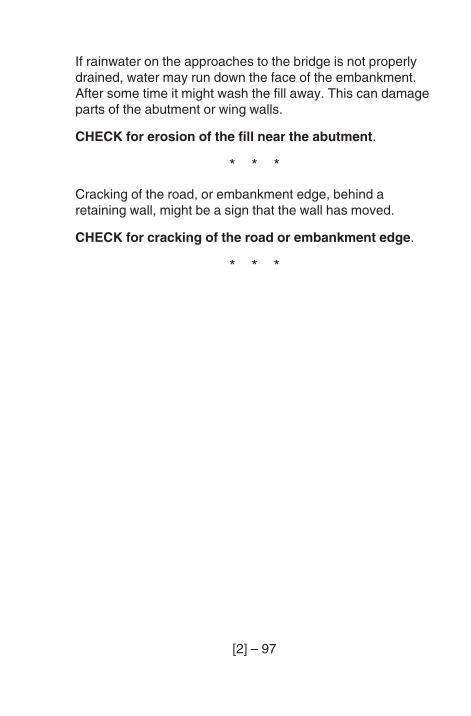
[2] – 97
If rainwater on the approaches to the bridge is not properlydrained, water may run down the face of the embankment.After some time it might wash the fill away. This can damageparts of the abutment or wing walls.
CHECK for erosion of the fill near the abutment.
* * *
Cracking of the road, or embankment edge, behind aretaining wall, might be a sign that the wall has moved.
CHECK for cracking of the road or embankment edge.
* * *
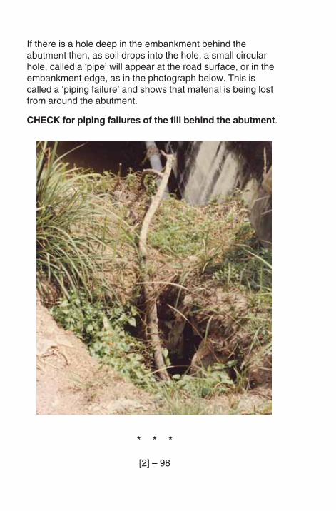
[2] – 98
If there is a hole deep in the embankment behind theabutment then, as soil drops into the hole, a small circularhole, called a ‘pipe’ will appear at the road surface, or in theembankment edge, as in the photograph below. This iscalled a ‘piping failure’ and shows that material is being lostfrom around the abutment.
CHECK for piping failures of the fill behind the abutment.
* * *
[2] – 99
PILED WALLS
Piled walls are used at the bottom of embankments toprevent the river scouring away the fill around the abutment.Piled walls can be made of steel (usually sheet piles), ortimber (usually logs), and sometimes concrete.
CHECK for forward movement of the piles caused by riverscour. If large sections of the wall have moved forward, theproblem is serious. Small movements are not serious.
* * *
CHECK for deterioration of the piles:
Steel piles: look for corrosion.
Timber piles: look for decay.
Steel andtimber piles: look for damage caused by debris.
Concrete: look for cracking and exposed reinforcement.
* * *
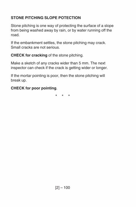
[2] – 100
STONE PITCHING SLOPE POTECTION
Stone pitching is one way of protecting the surface of a slopefrom being washed away by rain, or by water running off theroad.
If the embankment settles, the stone pitching may crack.Small cracks are not serious.
CHECK for cracking of the stone pitching.
Make a sketch of any cracks wider than 5 mm. The nextinspector can check if the crack is getting wider or longer.
If the mortar pointing is poor, then the stone pitching willbreak up.
CHECK for poor pointing.
* * *
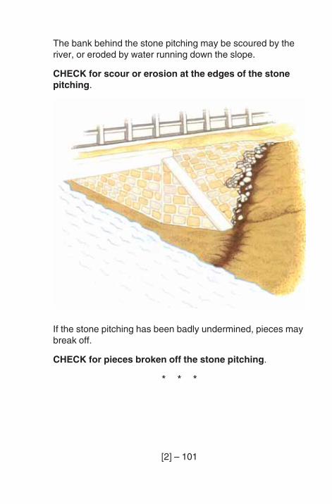
[2] – 101
The bank behind the stone pitching may be scoured by theriver, or eroded by water running down the slope.
CHECK for scour or erosion at the edges of the stonepitching.
If the stone pitching has been badly undermined, pieces maybreak off.
CHECK for pieces broken off the stone pitching.
* * *
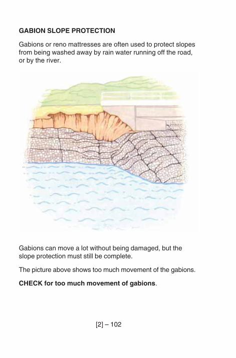
[2] – 102
GABION SLOPE PROTECTION
Gabions or reno mattresses are often used to protect slopesfrom being washed away by rain water running off the road,or by the river.
Gabions can move a lot without being damaged, but theslope protection must still be complete.
The picture above shows too much movement of the gabions.
CHECK for too much movement of gabions.
[2] – 103
Make a note it:
– the slope protection has settled so far that the top of theslope is not protected (the road edge may have cracked);
– there is bad scour at the bottom of the slope.
* * *
The wires which make up the gabion boxes and the wireswhich tie the boxes together must be in good condition.
CHECK for damage to the gabion wires and ties.
* * *
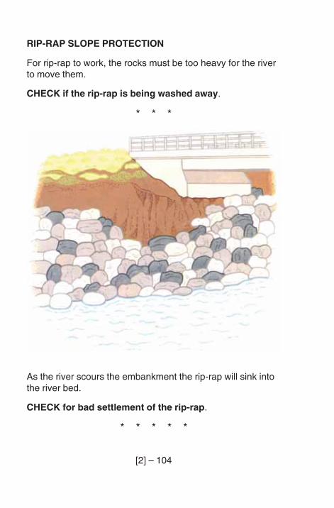
[2] – 104
RIP-RAP SLOPE PROTECTION
For rip-rap to work, the rocks must be too heavy for the riverto move them.
CHECK if the rip-rap is being washed away.
* * *
As the river scours the embankment the rip-rap will sink intothe river bed.
CHECK for bad settlement of the rip-rap.
* * * * *
[2] – 105
BED PROTECTION
It is important that the river bed under a bridge is notdamaged by the river.
CHECK for large holes in the river bed under or near thebridge.
* * *
If the river flows fast and the river bed is soft, the bed may beprotected with:
– stone pitching;
– concrete;
– gabions;
– rip-rap.
[2] – 106
STONE PITCHING OR CONCRETE BED PROTECTIONAND APRONS
The river often scours the river bed away at the edge of thebed protection. Small scour holes are not important. If a holegoes under the bed protection, you should report it.
CHECK for scour at the edge of the bed protection. Makea note of where the scour is and draw a sketch.
* * *
Cracks in the surface of bed protection are usually becauseof settlement.
CHECK for cracking. For mass concrete and stone pitching,only report large cracks. For reinforced concrete, report allcracks.
To find cracks, first use a spade to scrape off any sand ordebris. Then look carefully for any cracks. If you find cracks,draw a sketch of them.
* * *
CHECK for any signs of spalling of concrete or stonesmissing from stone pitching.
* * *
[2] – 107
Stone carried by the river often cause erosion of the surfaceof the concrete.
CHECK for erosion of the surface of the concrete orstone pitching.
* * *
For reinforced concrete bed protection, if there is spalling orerosion, the reinforcement may be corroding.
CHECK for corrosion of reinforcement.
* * *
[2] – 108
GABION BED PROTECTION AND APRONS
Gabions or reno mattresses used as river bed protectionhave a very big advantage. They are flexible, so that whenscour takes place, the edge of the gabion drops down to fillthe hole.
Because of this, scour is not usually a problem when thegabions are in good condition.
CHECK for signs that the gabions have broken awayfrom the pier or abutment. If this happens the river coulddestroy the bed protection very quickly.
* * *
CHECK for damage to gabion wires or ties. Look carefullyfor broken wires or corrosion of the wires.
* * *
[2] – 109
RIP-RAP BED PROTECTION AND APRONS
Rip-rap is often used to prevent scour damage to piers. It issometimes necessary to put down more rip-rap to replace rip-rap lost during floods, or which has settled into the river bed.
CHECK for loss of rip-rap. If you think that some rip-raphas been lost, make a sketch of the rip-rap you can see.
Is this less than at the last inspection? If so, more rip-rapmight be needed.
* * * * *
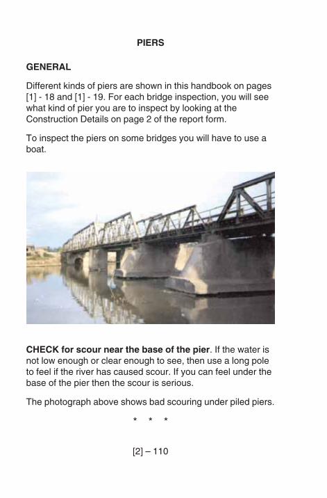
[2] – 110
PIERS
GENERAL
Different kinds of piers are shown in this handbook on pages[1] - 18 and [1] - 19. For each bridge inspection, you will seewhat kind of pier you are to inspect by looking at theConstruction Details on page 2 of the report form.
To inspect the piers on some bridges you will have to use aboat.
CHECK for scour near the base of the pier. If the water isnot low enough or clear enough to see, then use a long poleto feel if the river has caused scour. If you can feel under thebase of the pier then the scour is serious.
The photograph above shows bad scouring under piled piers.
* * *
[2] – 111
If the caissons or piles are exposed they can be damaged, orthe piles can corrode.
CHECK for damage to caissons or piles, or corrosion ofpiles.
* * *
A pier will move if its foundation fails due to scour, or due tooverloading of the bridge. It may also move due to impactfrom a boat or due to an earthquake. Movement of the piercan cause:
– one expansion joint to close and the other expansionjoint to open;
– damage to a continuous superstructure.
CHECK for movement of the pier. To do this:
– look along the line of the piers, if there are other piers, tosee if one is out of line;
– look along the top of the bridge to see if the bridge is asmooth line. If there is a hollow at a pier then the pierhas settled;
– look carefully at the expansion joints and bearings.
* * *
Boats or floating logs can damage river piers. Vehicles candamage the piers of bridges over roads.
CHECK for impact damage due to boats, floating logs, orvehicles.
* * *
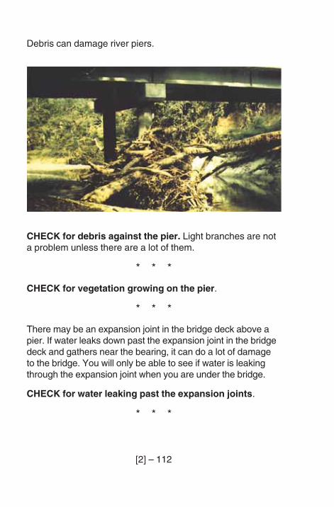
[2] – 112
Debris can damage river piers.
CHECK for debris against the pier. Light branches are nota problem unless there are a lot of them.
* * *
CHECK for vegetation growing on the pier.
* * *
There may be an expansion joint in the bridge deck above apier. If water leaks down past the expansion joint in the bridgedeck and gathers near the bearing, it can do a lot of damageto the bridge. You will only be able to see if water is leakingthrough the expansion joint when you are under the bridge.
CHECK for water leaking past the expansion joints.
* * *
[2] – 113
CONCRETE PIERS
CHECK for cracking of the concrete. Make a sketchshowing where important cracks are.
Look carefully for cracks:
– around bearings;
– in pilecaps;
– in beams over columns.
* * *
CHECK for spalling of the concrete. Mark spalled areas ona sketch.
* * *
CHECK for corrosion of reinforcement. Look for ruststains from cracks and look where concrete has spalled.Where concrete has spalled measure the concrete coverto reinforcement, and measure how much of the bar hasbeen lost.
* * *
CHECK for poor concrete. Look for honeycombing andchemical attack.
* * *
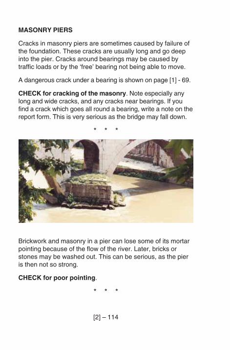
[2] – 114
MASONRY PIERS
Cracks in masonry piers are sometimes caused by failure ofthe foundation. These cracks are usually long and go deepinto the pier. Cracks around bearings may be caused bytraffic loads or by the ‘free’ bearing not being able to move.
A dangerous crack under a bearing is shown on page [1] - 69.
CHECK for cracking of the masonry. Note especially anylong and wide cracks, and any cracks near bearings. If youfind a crack which goes all round a bearing, write a note on thereport form. This is very serious as the bridge may fall down.
* * *
Brickwork and masonry in a pier can lose some of its mortarpointing because of the flow of the river. Later, bricks orstones may be washed out. This can be serious, as the pieris then not so strong.
CHECK for poor pointing.
* * *
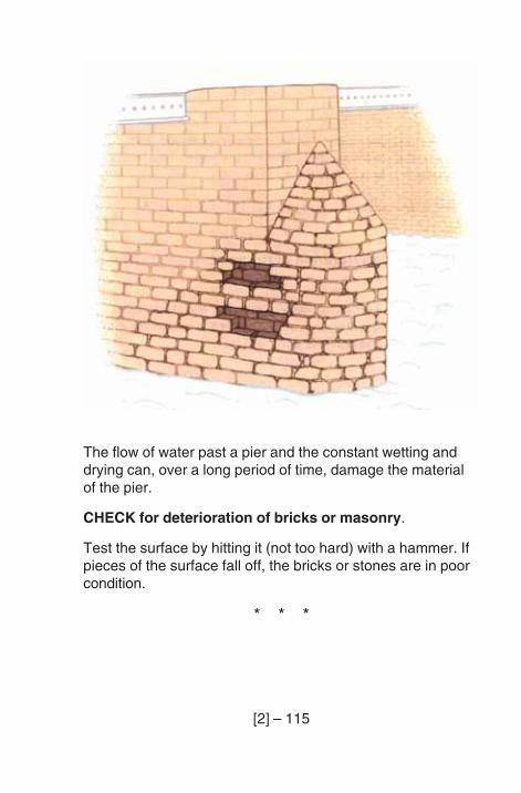
[2] – 115
The flow of water past a pier and the constant wetting anddrying can, over a long period of time, damage the materialof the pier.
CHECK for deterioration of bricks or masonry.
Test the surface by hitting it (not too hard) with a hammer. Ifpieces of the surface fall off, the bricks or stones are in poorcondition.
* * *
[2] – 116
STEEL PIERS
Floating vegetation, such as branches and grasses, cancatch on the steelwork and collect in the joints. This keepsthe joints wet and makes them corrode.
CHECK for debris in the joints of the steelwork.
* * *
CHECK for deterioration of the paint or galvanising.
* * *
CHECK for corrosion, especially near the water level. If thepier is in salt water, look especially at the part of the pierbetween high tide and low tide.
* * *
Steel piers may be damaged by boats, or logs carried by theriver in flood. If debris collects, then the river can push thepier very hard.
CHECK for bends in steel members or joints.
* * *
CHECK for loose bolts or rivets.
* * *
CHECK for cracking. Look carefully near the bearings forloose bolts or cracks in the steel.
* * *
[2] – 117
TIMBER PIERS
Floating vegetation and debris, can catch on the timber andcollect at the joints. This keeps the joints wet and makes thetimber decay.
CHECK for debris in the joints.
* * *
CHECK for decay. Look carefully at the joints. Look carefullynear the water when the pier is in fresh water.
* * *
CHECK for insect attack. Look carefully below the waterlevel when the pier is in salt water. Attack by teredo worms isvery common here.
* * *
CHECK for splitting of the timber. Note large splits, splitsnear bolt holes, and any splits where water can sit and causedecay.
* * *
CHECK for loose bolts or pins at joints.
* * *
The timbers of the pier may be bent if the pier is hit by a logor boat. They may also bend if the bridge is overloaded.
CHECK for bends in timbers.
* * *
[2] – 118
Most timber piers have some parts made of steel, such asplates at the joints. Often these steel joint plates and fixingscorrode at river level.
CHECK for damaged or corroded steel parts.
Look for:
– Deterioration of paint or galvanising.
– Corrosion.
– Bends.
– Cracking, especially near welds.
* * * * *
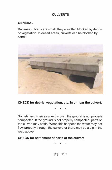
[2] – 119
CULVERTS
GENERAL
Because culverts are small, they are often blocked by debrisor vegetation. In desert areas, culverts can be blocked bysand:
CHECK for debris, vegetation, etc, in or near the culvert.
* * *
Sometimes, when a culvert is built, the ground is not properlycompacted. If the ground is not properly compacted, parts ofthe culvert may settle. When this happens the water may notflow properly through the culvert, or there may be a dip in theroad above.
CHECK for settlement of parts of the culvert.
* * *
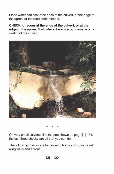
[2] – 120
Flood water can scour the ends of the culvert, or the edge ofthe apron, or the road embankment.
CHECK for scour at the ends of the culvert, or at theedge of the apron. Mark where there is scour damage on asketch of the culvert.
* * *
On very small culverts, like the one shown on page [1] - 84,the last three checks are all that you can do.
The following checks are for larger culverts and culverts withwing walls and aprons.
[2] – 121
CONCRETE CULVERT BARRELS
If you need them, there are notes on inspecting reinforcedconcrete on pages [1] - 43 to [1] - 55.
CHECK for cracking.
* * *
CHECK for spalling.
* * *
CHECK for corrosion of reinforcement.
* * *
CHECK for poor concrete. Make a sketch to show anycracking, spalling, corrosion or poor concrete.
* * *
[2] – 122
CORRUGATED STEEL CULVERTS
Corrugated steel culverts can be different shapes. Mostlythey are circular, oval or arched.
A culvert can change shape because it was badly con-structed, or because the traffic above it is too heavy. If acorrugated steel culvert changes shape it can collapse. Evena small change in shape of a culvert can make it collapse.
CHECK for change of shape of the culvert barrel.
* * *
Corrosion can be a problem with corrugated steel culverts.Most culverts are galvanised, but some are protected bypaint. Stones and other debris can damage the galvanisingand paint. If this happens, there will be corrosion.
CHECK for damage or deterioration to paint orgalvanising.
* * *
CHECK for corrosion of steel. Corrosion can also begin onthe outside of the culvert, which you cannot see. A commonplace to find corrosion is next to the bolts between sectionsof the culvert.
* * *
The bolted joints are very important to the strength of theculvert. All bolts must be tight and in good order.
CHECK for loose or corroded bolts.
* * *
[2] – 123
CULVERT APRONS
Like bridges, culverts may be protected from scour byaprons. These aprons can be made of gabions or renomattresses, concrete, or stone pitching.
Sometimes, scour causes the apron to settle at the edge.Concrete or stone pitching may crack and break up.
CHECK for cracking and damage to concrete or stonepitching.
* * *
Gabion or reno mattress wires or ties may corrode or bedamaged by debris. The stones in the gabions may then bewashed away and the gabion will not do its job. The gabionbaskets can settle or move due to scour.
CHECK for damage to gabions.
* * *
[2] – 124
HEADWALLS
Headwalls retain the embankment fill at the ends of theculvert. They can be made of concrete or masonry. If aheadwall settles or is pushed forward, water can wash awaythe embankment fill at the joint between the headwall and theculvert barrel. This can damage the embankment.
CHECK for movement of the headwalls. Look carefully atthe joint between the headwalls and the culvert barrel.
* * *
For Concrete HeadwalIs
CHECK for cracking, spalling, corrosion of thereinforcement, or poor concrete. Make a note of the kindof problem you find, and make a sketch to show where theproblem is, and how big the problem is.
* * *
For Masonry Headwalls
CHECK for cracking, poor pointing or deterioration ofthe bricks or stones. Make a note of the kind of problemyou find, and make a sketch to show where the problem is,and how big the problem is.
* * * * *
APPENDICES
A. WORD LIST.
B. EQUIPMENT LIST.
C. SAFETY DURING INSPECTIONS.
D. EXAMPLE OF A COMPLETED REPORT FORM.

A – 1
APPENDIX A
WORD LIST
This is a list of engineering words that are used in this book,and their meanings.
The first time these words appear in the book, they areprinted in CAPITAL LETTERS, so that you will know thatthey are explained here.
In some of these notes you are asked to look at a page wherethere is a picture or some more information that will be helpful.
The picture on page [2] - 76 shows most of the parts of aBailey bridge. The Bailey bridge parts not shown in thepicture are described in this word list.
ABUTMENT: end support of a bridge, see pages [1] - 6and [1]-17.
APPROACH EMBANKMENTS: the earthwork that carriesthe road up to the bridge.
APPROACH ROAD: the road near the bridge.
APRON: bed protection at the mouth of a culvert,see page [2]-120.
ARCH: curved bridge structure, see page [1] - 12.
BAILEY BRIDGE: a type of steel truss bridge designed forquick assembly, see page [2] - 75.
BALLAST WALL: abutment wall above bearing shelf,see page [1]-17.
A – 2
BANK SEAT ABUTUMENT: an abutment set well up theriver bank; above the usual river level, see pages [1] - 14and [1] -15.
BARREL (of arch): the main part of an arch which supportsfill and road, see page [1] - 12.
BARREL (of culvert): the pipe or box part of a culvert wherewater flows.
BEAM: narrow member which spans between supports; forexample a log in a log bridge.
BEARING: this part is between the deck and the abutment orpier. It carries the weight of the deck, and slides or hinges toallow the deck to move. See pages [1] - 16, [1] - 20 and [1] - 21.
BEARING BOLT: type of fixing for joints in steel or timber,see page [1] - 65.
BEARING SHELF: part of the abutment, where thesuperstructure rests, see page [1] - 16.
BED (RIVER BED): the bottom of the river.
BED (AS IN ‘BEDDED IN MORTAR’): fix in place with(mortar).
BOOM: top or bottom part of a truss, see page [1] - 1 0.
BOX GIRDER: a hollow beam with a box shape,see page [1]-7.
BRACING: parts of a bridge which help to keep it stiff andnot change shape, see page [1] - 10.
BULGING: where a flat place changes shape and is bent.
A – 3
CAISSONS: type of masonry or concrete foundations, builtlike a tube, see page [1] - 13.
CANTILEVER: a beam, fixed at one end and free to move atthe other.
CHORD: On a Bailey bridge, a chord is a long steel platebolted to the truss to make it stronger.
COMPRESSION (STRONG IN COMPRESSION): beingpushed together, see page [1] - 44.
CONDENSATION: water from the air that settles on a coldsurface.
CORRODE, CORRODED (STEEL): to be attacked by rust.
CORROSION: damage done to steel (or other metal) by air,water, salts, etc.
CORRUGATED STEEL: thin sheets of steel which havebeen shaped to make them strong.
COVER (COVER TO THE BAR): the thickness of theconcrete over the reinforcement at that place.
CROSS GIRDERS: steel beams that connect two trusses.
CULVERT: a tube or box to carry water under a road, seepages [1]-83 and [1]-84.
DEBRIS: rubbish and other unwanted things.
DECAY: rotting of wood, making it soft and weak; caused bydampness and fungus.
DECK (DECKING): top of bridge superstructure,see page [1]-7.
A – 4
DETERIORATE, DETERIORATED: to become worse; to getinto a bad condition.
DOUBLE STOREY BRIDGE: bridge made of two trusses,one on top of the other, each side of the bridge.
DOWNSTREAM: where the river flows away from a bridge.
DRAINAGE: system for taking waste water (usually rainwater) away.
EMBANKMENT: soil bank which supports the road,see pages [1] - 6 and [1] -17.
EROSION, ERODING: removal of earth by wind, rain orflowing water.
FILL (FILL IN FRONT OF THE ABUTMENT): soil placed infront of the abutment.
FIXED (FIXED BEARING): not able to move, see page [1] - 21.
FLANGE: the top or bottom of a girder, see page [2] - 47.
FOUNDATIONS: the lowest part of the bridge which sits onor in the ground.
FUNGUS: type of plant which grows on decayed timber.
GABION: wire basket filled with stones, see pages [1] - 81and [2] - 102.
GALVANISING: a thin layer of zinc on steel to protect itagainst corrosion.
GIRDER: a beam, usually made of steel, see page [2] - 47.
GROYNE: a wall built to change the flow of a river andprotect the river bank from scour.
A – 5
HEADWALL: a wall at the end of a culvert to hold the soil fillabove the culvert pipe.
HONEYCOMBING: badly made concrete with lots of holes,see page [1] - 54.
IMPACT: to hit hard, as when a vehicle hits a bridge parapet.
INVERT: the bottom of a channel, usually paved.
KERB: the step between the road and footpath,see page [1] – 7.
LAMINATIONS: thin layers, like pages of a book.
LANDSLIDE: a lot of soil and rocks slipping down amountain or hill.
LUBRICATION SYSTEM: a system to supply oil or grease toa mechanical bridge bearing.
MAINTAIN (as in WELL MAINTAINED): to look aftercarefully and repair when it is necessary.
MARSDEN MATTING: a type of steel decking with holes,see page [2] - 22.
MASONRY: bricks or stones set together with mortar.
MASS CONCRETE: concrete without any steel in it.
MOISTURE: some water or dampness.
OVERBRIDGE: a bridge over a road.
OVERLOADED: carrying too much weight.
PANEL: a flat frame or plate.
A – 6
PARAPET: a wall or rail along the edge of a bridge,see page [1] - 6.
PIER: a support between abutments for bridges with morethan one span, see page [1] - 9.
PILE: a long, thin, foundation driven deep into the ground,see page [1]-13.
PILED: WALLS: walls made of long pieces of material driveninto the ground.
PLATE (STEEL PLATE): a flat, stiff piece of steel.
POINTING: the mortar between bricks or stones in masonry.
PRESTRESSED (as in PRESTRESSED CONCRETE): away of making concrete stronger with steel bars.
PTFE: a slippery white material used in bearings.
REINFORCEMENT: steel bars in reinforced concrete, tomake it stronger.
RENDERING: a thin layer of mortar put on masonry orbrickwork to protect it.
RENO MATTRESS: a long thin gabion.
RETAINING WALL: a wall to hold back soil, see page [1]-17.
RIP-RAP: a layer of loose rocks to protect a river bed fromscour, see page [2] - 104.
RIVER TRAINING WORKS: constructions to stop the riverchanging its path, see page [2] - 39.
SAFETY PINS: the small clips on a Bailey bridge, that stopthe panel pins from falling out.
A – 7
SCOUR: holes in the river bed or bank caused by the flow ofthe river.
SEATING: the place where one part rests on another part.For example the place where a bearing is set on a pier orabutment.
SERVICES: cables and pipes belonging to other authorities.
SETTLEMENT: small movement downwards of a structure.
SHEET PILED WALL: a wall made from steel panels ortimber boards hammered into the ground.
SLAB (CONCRETE SLAB): a large piece of concrete (forexample a bridge deck).
SPACER PLATES: plates which are put between two otherparts.
SPALL: to break off in a piece.
SPALLING: an area where concrete has broken away.
SPAN: the part of a bridge, or the distance, between thesupports.
SPANDREL (SPANDREL WALLS): the side walls of amasonry arch bridge, see page [1] - 12.
SPREAD FOUNDATIONS: wide base to a pier or abutment,usually made of reinforced concrete.
STIFFENER: piece of steel used to strengthen a steel plate orgirder and make it stronger against bending, see page [2] - 47.
STONE PITCHING: stones set in cement mortar to cover asloping bank or an invert.
A – 8
STRINGER: a horizontal deck member, see page [1] - 10.
STRUCTURAL (STRUCTURAL MEMBER): an importantpart of a bridge, for example a girder.
SUBSTRUCTURE: all the parts of a bridge, except for thesuperstructure, i.e. abutments, piers, etc.
SUPERSTRUCTURE: all of the deck, including parapets,trusses, beams and running surface.
SUSPENDED SPAN: the middle span of a cantilever bridge,see page [1] - 25.
TENSION (STRONG IN TENSION): pulling apart,see page [1] - 44.
TRUSS: a type of girder made from many small beams,see page [1] - 10.
TRUSS BRIDGE: a bridge which has truss spans,see page [1] - 10
UPSTREAM: the direction where the water in the river iscoming from.
VIBRATION: repeated small movements caused by a heavyvehicle or perhaps an earthquake.
WATER BAR: a seal to stop water, see page [1] - 24.
WEB: the part of a girder that joins the flanges,see page [2] - 47.
WEEP HOLE: a hole to allow water to come through,see page [1] - 17.
WING WALLS: walls which are at the side of the abutmentand part of it, see page [1] - 17.

A – 9
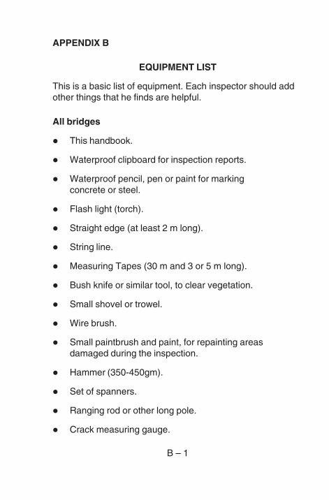
B – 1
APPENDIX B
EQUIPMENT LIST
This is a basic list of equipment. Each inspector should addother things that he finds are helpful.
All bridges
! This handbook.
! Waterproof clipboard for inspection reports.
! Waterproof pencil, pen or paint for markingconcrete or steel.
! Flash light (torch).
! Straight edge (at least 2 m long).
! String line.
! Measuring Tapes (30 m and 3 or 5 m long).
! Bush knife or similar tool, to clear vegetation.
! Small shovel or trowel.
! Wire brush.
! Small paintbrush and paint, for repainting areasdamaged during the inspection.
! Hammer (350-450gm).
! Set of spanners.
! Ranging rod or other long pole.
! Crack measuring gauge.
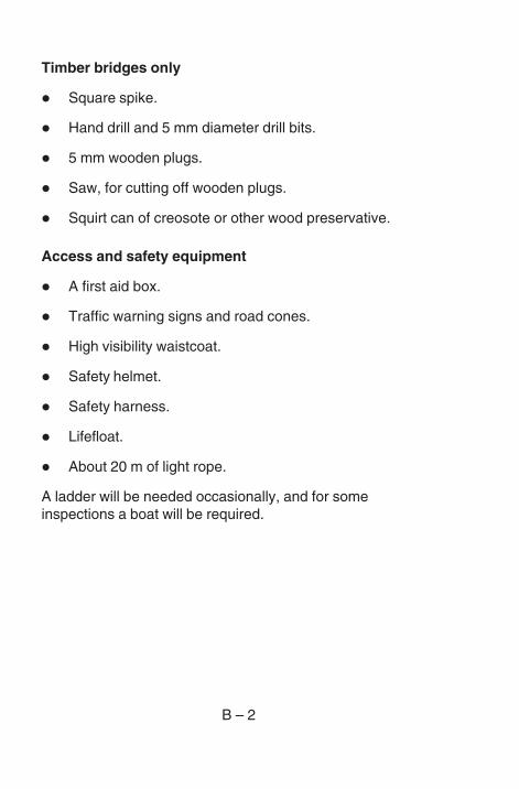
B – 2
Timber bridges only
! Square spike.
! Hand drill and 5 mm diameter drill bits.
! 5 mm wooden plugs.
! Saw, for cutting off wooden plugs.
! Squirt can of creosote or other wood preservative.
Access and safety equipment
! A first aid box.
! Traffic warning signs and road cones.
! High visibility waistcoat.
! Safety helmet.
! Safety harness.
! Lifefloat.
! About 20 m of light rope.
A ladder will be needed occasionally, and for someinspections a boat will be required.
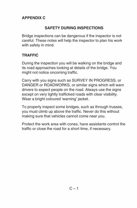
C – 1
APPENDIX C
SAFETY DURING INSPECTIONS
Bridge inspections can be dangerous if the inspector is notcareful. These notes will help the inspector to plan his workwith safety in mind.
TRAFFIC
During the inspection you will be walking on the bridge andits road approaches looking at details of the bridge. Youmight not notice oncoming traffic.
Carry with you signs such as SURVEY IN PROGRESS, orDANGER or ROADWORKS, or similar signs which will warndrivers to expect people on the road. Always use the signsexcept on very lightly trafficked roads with clear visibility.Wear a bright coloured ‘warning’ jacket.
To properly inspect some bridges, such as through trusses,you must climb up above the traffic. Never do this withoutmaking sure that vehicles cannot come near you.
Protect the work area with cones, have assistants control thetraffic or close the road for a short time, if necessary.
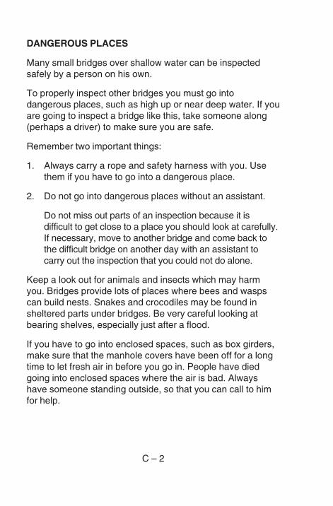
C – 2
DANGEROUS PLACES
Many small bridges over shallow water can be inspectedsafely by a person on his own.
To properly inspect other bridges you must go intodangerous places, such as high up or near deep water. If youare going to inspect a bridge like this, take someone along(perhaps a driver) to make sure you are safe.
Remember two important things:
1. Always carry a rope and safety harness with you. Usethem if you have to go into a dangerous place.
2. Do not go into dangerous places without an assistant.
Do not miss out parts of an inspection because it isdifficult to get close to a place you should look at carefully.If necessary, move to another bridge and come back tothe difficult bridge on another day with an assistant tocarry out the inspection that you could not do alone.
Keep a look out for animals and insects which may harmyou. Bridges provide lots of places where bees and waspscan build nests. Snakes and crocodiles may be found insheltered parts under bridges. Be very careful looking atbearing shelves, especially just after a flood.
If you have to go into enclosed spaces, such as box girders,make sure that the manhole covers have been off for a longtime to let fresh air in before you go in. People have diedgoing into enclosed spaces where the air is bad. Alwayshave someone standing outside, so that you can call to himfor help.
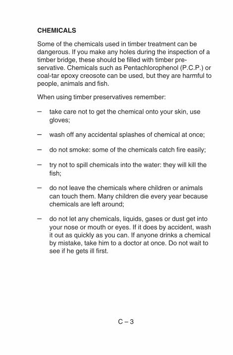
C – 3
CHEMICALS
Some of the chemicals used in timber treatment can bedangerous. If you make any holes during the inspection of atimber bridge, these should be filled with timber pre-servative. Chemicals such as Pentachlorophenol (P.C.P.) orcoal-tar epoxy creosote can be used, but they are harmful topeople, animals and fish.
When using timber preservatives remember:
– take care not to get the chemical onto your skin, usegloves;
– wash off any accidental splashes of chemical at once;
– do not smoke: some of the chemicals catch fire easily;
– try not to spill chemicals into the water: they will kill thefish;
– do not leave the chemicals where children or animalscan touch them. Many children die every year becausechemicals are left around;
– do not let any chemicals, liquids, gases or dust get intoyour nose or mouth or eyes. If it does by accident, washit out as quickly as you can. If anyone drinks a chemicalby mistake, take him to a doctor at once. Do not wait tosee if he gets ill first.
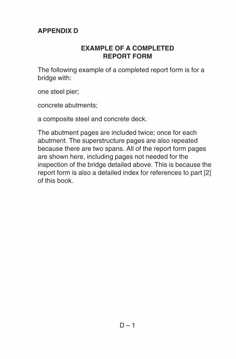
D – 1
APPENDIX D
EXAMPLE OF A COMPLETEDREPORT FORM
The following example of a completed report form is for abridge with:
one steel pier;
concrete abutments;
a composite steel and concrete deck.
The abutment pages are included twice; once for eachabutment. The superstructure pages are also repeatedbecause there are two spans. All of the report form pagesare shown here, including pages not needed for theinspection of the bridge detailed above. This is because thereport form is also a detailed index for references to part [2]of this book.
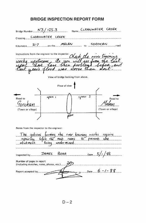
D – 2
BRIDGE INSPECTION REPORT FORM
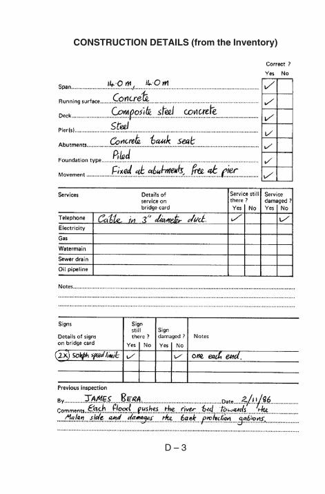
D – 3
CONSTRUCTION DETAILS (from the Inventory)
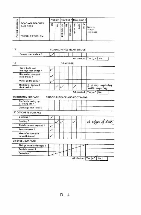
D – 4
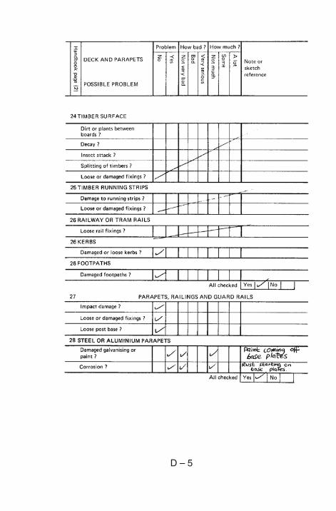
D – 5
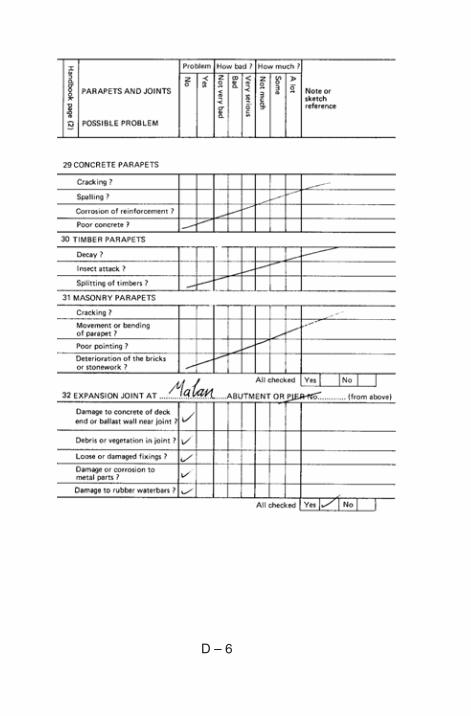
D – 6
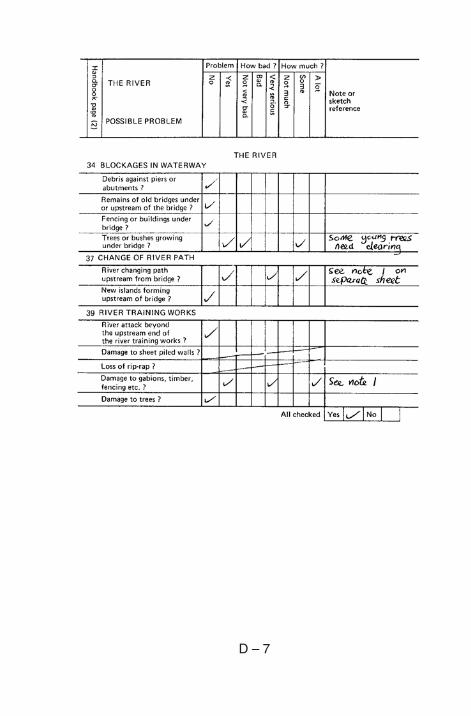
D – 7
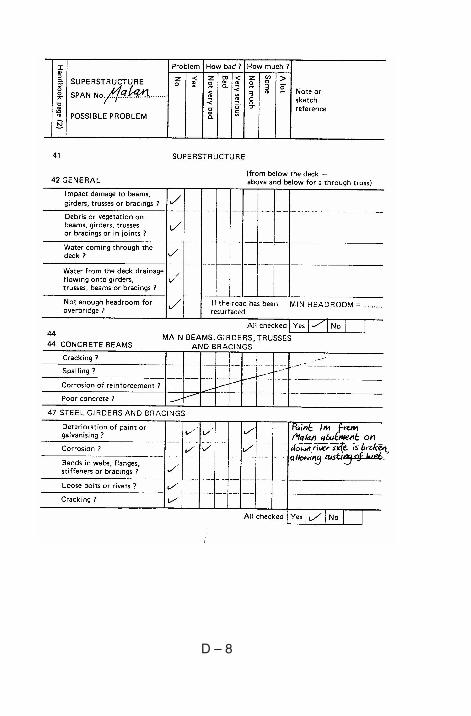
D – 8
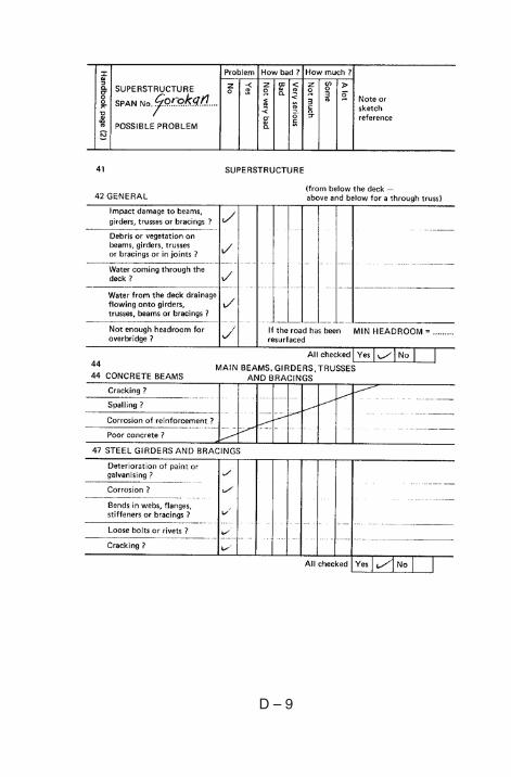
D – 9
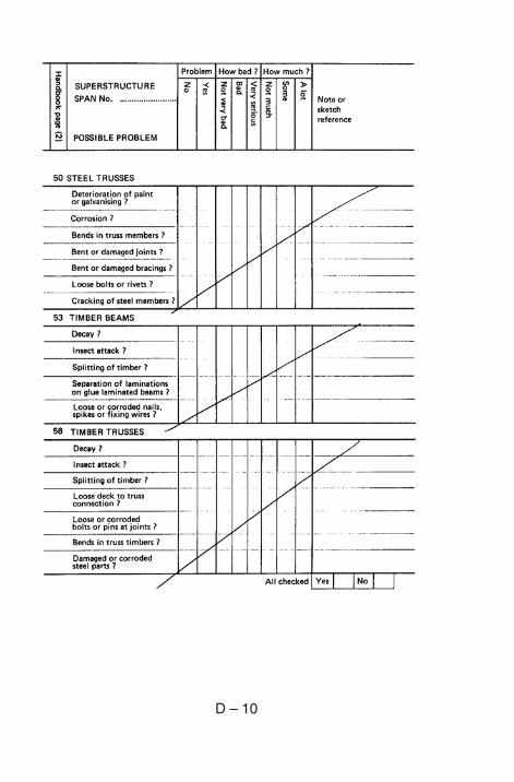
D – 10
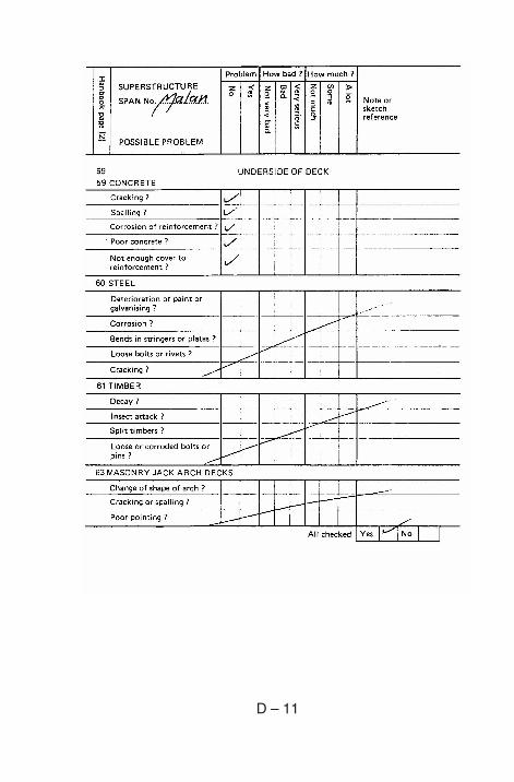
D – 11
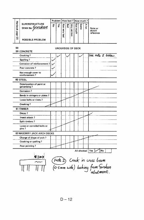
D – 12
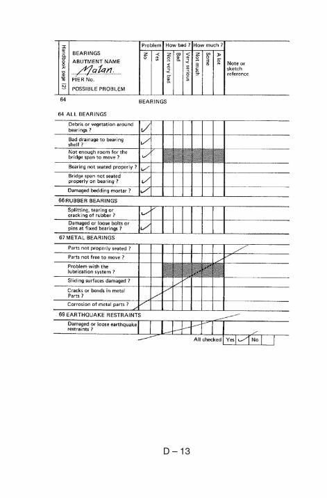
D – 13
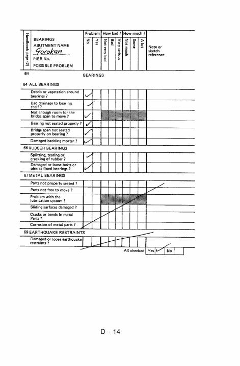
D – 14
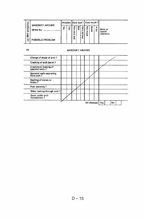
D – 15
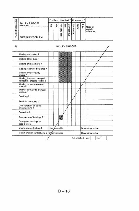
D – 16
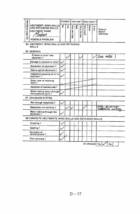
D – 17
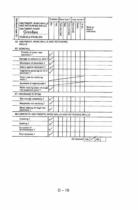
D – 18
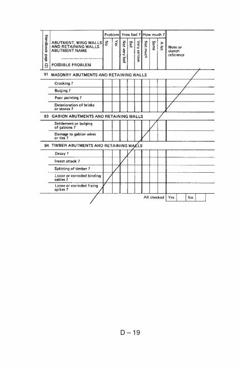
D – 19
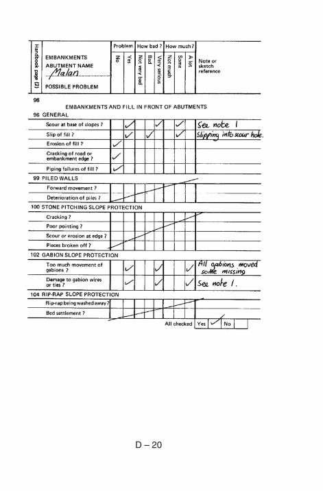
D – 20
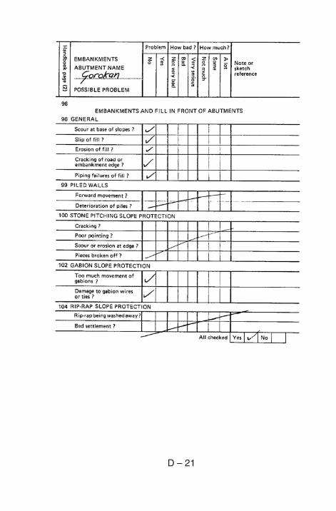
D – 21
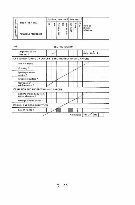
D – 22
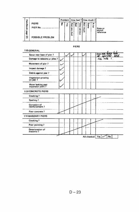
D – 23
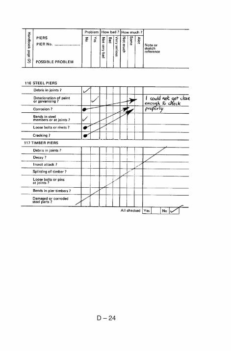
D – 24
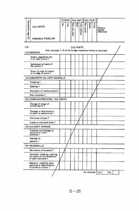
D – 25
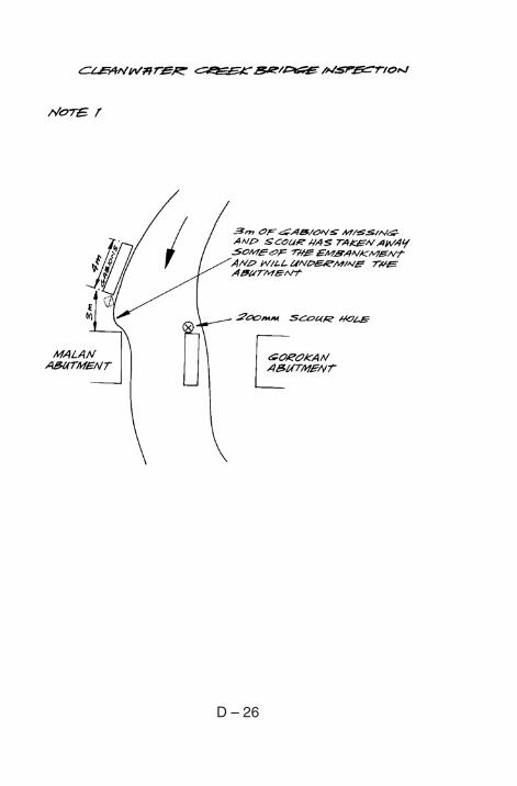
D – 26