Embed Size (px)
Citation preview
BE2870 Operating Instructions
(Translation of original)
Brinkmann Pumpen Edition 11/2017 Page 1 of 10
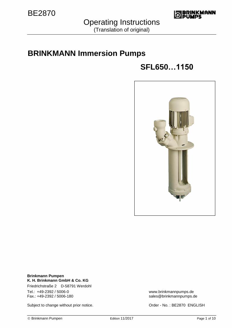
BRINKMANN Immersion Pumps
SFL650…1150
Brinkmann Pumpen K. H. Brinkmann GmbH & Co. KG
Friedrichstraße 2 D-58791 Werdohl
Tel.: +49-2392 / 5006-0 www.brinkmannpumps.de Fax.: +49-2392 / 5006-180 [email protected] Subject to change without prior notice. Order - No. : BE2870 ENGLISH
BE2870 Edition 11/2017 Page 2 of 10
Brinkmann Immersions pumps of the series SFL650…1150 Contents 1 Indication to the manual .................................... 2 2 Description of product .................................... 2-3 3 Safety instructions ............................................. 4 4 Transport and storage ....................................... 4 5 Installation and connection ................................ 5 6 Start up / Shut down .......................................... 6 7 Operation ........................................................... 6 8 Servicing and Maintenance ............................... 6
9 Trouble shooter’s guide ..................................... 7 10 Spare part ...................................................... 8-9 11 Repair ............................................................... 9 12 Disposal ............................................................ 9 13 EC declaration of conformity ........................... 10
1 Indication to the manual
This operating manual gives basic instructions which are to be observed during installation, opera-tion and maintenance of the pump. It is therefore imperative that this manual be read by the respon-sible personnel and operator prior to assembly and commissioning. It is always to be kept available at the installation site.
1.1 Identification of safety instructions in the operating manual
Safety instructions given in this manual non-compliance with which would affect safety are identified by the following symbol
Safety sign according with ISO 3864 – B.3.1
or where electrical safety is involved, with:
Safety sign according with ISO 3864 – B.3.6
Where non-compliance with the safety instructions may cause a risk to the machine and it’s function the word
ATTENTION
is inserted.
2 Description of product
2.1 General description of the pump Pumps of this type are one-stage rotary pumps where the impellers are fixed on the driving shaft extension. The pump shaft and motor shaft are interconnected by means of a shaft clamp. Pump and motor form a compact and space-saving unit. These pumps are fitted out with semi-open impel-lers and a suction screw. Vertically mounted pumps are equipped with a mounting flange. The pump end immerses into the tank and the motor extends vertically above the tank.
2.2 Intended use The immersion pumps of the series SFL are suita-ble for handling contaminated coolants within the limiting application in accordance with table 1. The SFL pumps are suitable for handling extremely inflated fluids.
Limit of Application (Table 1)
ATTENTION
The pumps are to be operated within their design limits. Applications outside of these limits are not approved. The manufacturer is not responsible for any damages resulting from use of the pumps in such applications.
Type SFL
Mediums Coolants, cooling- and cutting-oils.
Chip material
Aluminium, steel, coloured steels max. chip to coolant ratio by weight: 1.0%
Kinetic viscosity of the medium
...45 mm2/s
Temperature of medium
0 ... 80 °C
Particle-size in the medium
9 mm SFL650 17 mm SFL850 16 mm SFL1150
min. delivery volume
1% of Q max.
Dry running Dry running causes increased wear and should be avoided. During the test of the direction of rotation (< 30 s) permissible.
Switching-on frequency per hour for
The pump SFL should be operated in continual operation mode, not pulsed mode.
Ambient temperature
40 °C
Set-up altitude 1000 m
BE2870 Edition 11/2017 Page 3 of 10
2.3 Technical data
Type
Max. del. pressure bar / spec. weight 1
Max. del. volume l/min
Height1)
H mm
Depth of immersion
1)
h mm
Weight kg
Power 50 / 60 Hz kW
SFL650 / 220
/ 320
/ 450
/ 570
/ 770
/1000
1.5 700 464 220
320
450
570
770
1000
51
54
57
62
73
76
2.2 / 2.55
SFL850 / 230
/ 330
/ 460
/ 580
/ 780
/1010
1.7 950 464 230
330
460
580
780
1010
52
55
58
65
75
78
2.6 / 2.94
SFL1150 / 230
/ 330
/ 460
/ 580
/ 780
/1010
1.8 1100 503 230
330
460
580
780
1010
62
66
73
76
85
88
4.0 / 4.55
1) Dimensions in accordance with page 5
The motor is surface-cooled and compliant with DIN IEC 34 and EN 60034 (protection degree IP 55).
BE2870 Edition 11/2017 Page 4 of 10
3 Safety instructions When operating the pump, the safety instructions contained in this manual, the relevant national accident prevention regulations and any other service and safety instructions issued by the plant operator are to be observed.
3.1 Hazards in the event of non-compliance with the safety instructions
Non-compliance with the safety instructions may produce a risk to the personnel as well as to the environment and the machine and results in a loss of any right to claim damages. For example, non-compliance may involve the following hazards:
Failure of important functions of the ma-chines/plant
Failure of specified procedures of maintenance and repair
Exposure of people to electrical, mechanical and chemical hazards
Endangering the environment due to hazardous substances being released
3.2 Unauthorized modes of operation
Pump may not be used in potentially explosive environments!
Pump and discharge piping are not designed to hold any weight and may not be used as a step ladder.
3.3 Remaining Risk
Risk of Injury! Risk of squeezing or crushing body parts when installing or removing the pump exists. Proper and secured lifting tools must be used. Risk of burns! The pump must have cooled down sufficiently prior to commencing any repair, maintenance or installa-tion.
3.4 Qualification and training of operating personnel
The personnel responsible for operation, mainte-nance, inspection and assembly must be adequate-ly qualified. Scope of responsibility and supervision of the personnel must be exactly defined by the plant operator. If the staff does not have the neces-sary knowledge, they must be trained and instruct-ed, which may be performed by the machine manu-facturer or supplier on behalf of the plant operator. Moreover, the plant operator is to make sure that the contents of the operating manual are fully understood by the personnel.
3.5 Safety instructions relevant for operation
If hot or cold machine components involve hazards, they must be guarded against acci-dental contact.
Guards for moving parts (e.g. coupling) must not be removed from the machine while in opera-tion.
Any leakage of hazardous (e.g. explosive, toxic, hot) fluids (e.g. from the shaft seal) must be drained away so as to prevent any risk to per-sons or the environment. Statutory regulations are to be complied with.
Hazards resulting from electricity are to be prevented (see for example, the VDE Specifica-tions and the bye-laws of the local power supply utilities).
The pumps’ stability against falling over is not ensured unless it is properly mounted onto the tank.
The female threads on the motor MUST NOT be used to lift the entire pump and motor assembly.
3.6 Safety instructions relevant for mainte-nance, inspection and assembly work
Any work on the machine shall only be performed when it is at a standstill, it being imperative that the procedure for shutting down the machine described in this manual be followed. Pumps and pump units which convey hazardous media must be decontaminated. On completion of work all safety and protective facilities must be re-installed and made operative again. Prior to restarting the machine, the instructions listed under “Start up” are to be observed.
3.7 Signs on the pump It is imperative that signs affixed to the machine, e.g.:
arrow indicating the direction of rotation
symbols indicating fluid connections be observed and kept legible.
3.8 Unauthorized alterations and production of spare parts
Any modification may be made to the machine only after consultation with the manufacturer. Using spare parts and accessories authorized by the manufacturer is in the interest of safety. Use of other parts may exempt the manufacturer from any liability.
4 Transport and storage Protect the pump against damage when transport-ing. The pumps may only be transported in a horizontal position and hooks or straps must be attached on the motor and pump end. Do not use the pump shaft for connecting any transportation aids such as hooks or straps. Pumps must be drained prior to their storage. Store pump in dry and protected areas and protect it against penetration of foreign bodies. Always store pump above the freezing point!
BE2870 Edition 11/2017 Page 5 of 10
5 Installation and Connection
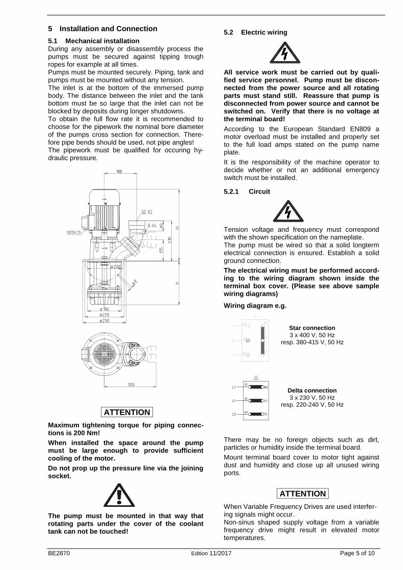
5.1 Mechanical installation During any assembly or disassembly process the pumps must be secured against tipping trough ropes for example at all times. Pumps must be mounted securely. Piping, tank and pumps must be mounted without any tension. The inlet is at the bottom of the immersed pump body. The distance between the inlet and the tank bottom must be so large that the inlet can not be blocked by deposits during longer shutdowns. To obtain the full flow rate it is recommended to choose for the pipework the nominal bore diameter of the pumps cross section for connection. There-fore pipe bends should be used, not pipe angles! The pipework must be qualified for occuring hy-draulic pressure.
ATTENTION
Maximum tightening torque for piping connec-tions is 200 Nm!
When installed the space around the pump must be large enough to provide sufficient cooling of the motor.
Do not prop up the pressure line via the joining socket.
The pump must be mounted in that way that rotating parts under the cover of the coolant tank can not be touched!
5.2 Electric wiring
All service work must be carried out by quali-fied service personnel. Pump must be discon-nected from the power source and all rotating parts must stand still. Reassure that pump is disconnected from power source and cannot be switched on. Verify that there is no voltage at the terminal board!
According to the European Standard EN809 a motor overload must be installed and properly set to the full load amps stated on the pump name plate.
It is the responsibility of the machine operator to decide whether or not an additional emergency switch must be installed.
5.2.1 Circuit
Tension voltage and frequency must correspond with the shown specification on the nameplate. The pump must be wired so that a solid longterm electrical connection is ensured. Establish a solid ground connection.
The electrical wiring must be performed accord-ing to the wiring diagram shown inside the terminal box cover. (Please see above sample wiring diagrams)
Wiring diagram e.g.
There may be no foreign objects such as dirt, particles or humidity inside the terminal board.
Mount terminal board cover to motor tight against dust and humidity and close up all unused wiring ports.
ATTENTION
When Variable Frequency Drives are used interfer-ing signals might occur. Non-sinus shaped supply voltage from a variable frequency drive might result in elevated motor temperatures.
Star connection
3 x 400 V, 50 Hz resp. 380-415 V, 50 Hz
Delta connection
3 x 230 V, 50 Hz resp. 220-240 V, 50 Hz
BE2870 Edition 11/2017 Page 6 of 10
6 Start up / Shut down
6.1 Start up
ATTENTION
Switch off at the mains. After connection the electrical wires, close the terminal box. Briefly start the motor (max. 30 sec.) and check the rotation according to the arrow on the top of the motor. If the direction is incorrect change over two of the power leads.
6.2 Shut down All service work must be carried out by qualified service personnel. Pump must be disconnected from the power source and all rotating parts must stand still. Reassure that pump is disconnected from power source and cannot be switched on. Verify that there is no voltage at the terminal board! Open terminal box and disconnect the power leads. Empty out the pump.
7 Operation
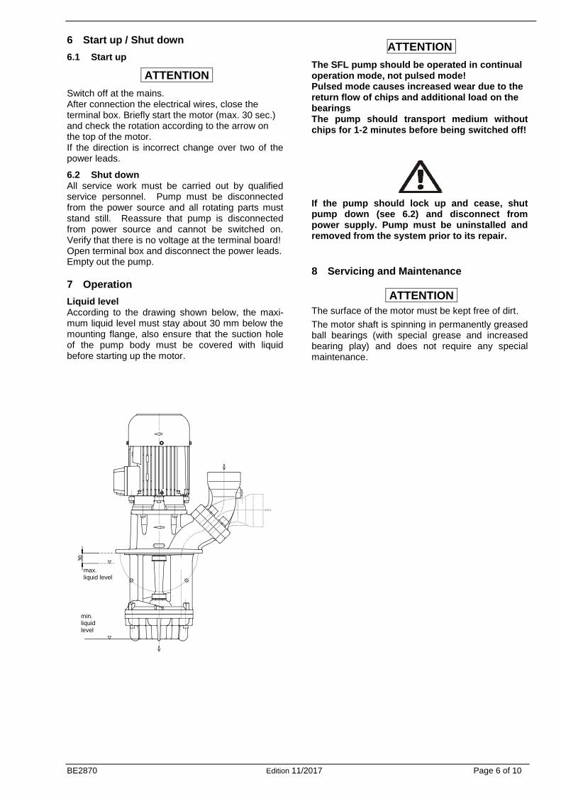
Liquid level According to the drawing shown below, the maxi-mum liquid level must stay about 30 mm below the mounting flange, also ensure that the suction hole of the pump body must be covered with liquid before starting up the motor.
ATTENTION
The SFL pump should be operated in continual operation mode, not pulsed mode! Pulsed mode causes increased wear due to the return flow of chips and additional load on the bearings The pump should transport medium without chips for 1-2 minutes before being switched off!
If the pump should lock up and cease, shut pump down (see 6.2) and disconnect from power supply. Pump must be uninstalled and removed from the system prior to its repair.
8 Servicing and Maintenance
ATTENTION
The surface of the motor must be kept free of dirt.
The motor shaft is spinning in permanently greased ball bearings (with special grease and increased bearing play) and does not require any special maintenance.
max. liquid level
min. liquid level
BE2870 Edition 11/2017 Page 7 of 10
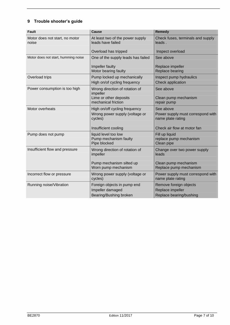
9 Trouble shooter’s guide
Fault Cause Remedy
Motor does not start, no motor noise
At least two of the power supply leads have failed Overload has tripped
Check fuses, terminals and supply leads . Inspect overload
Motor does not start, humming noise One of the supply leads has failed Impeller faulty Motor bearing faulty
See above Replace impeller Replace bearing
Overload trips Pump locked up mechanically
High on/of cycling frequency
Inspect pump hydraulics
Check application
Power consumption is too high Wrong direction of rotation of impeller Lime or other deposits mechanical friction
See above Clean pump mechanism repair pump
Motor overheats High on/off cycling frequency
Wrong power supply (voltage or cycles)
Insufficient cooling
See above
Power supply must correspond with name plate rating
Check air flow at motor fan
Pump does not pump liquid level too low Pump mechanism faulty Pipe blocked
Fill up liquid replace pump mechanism Clean pipe
Insufficient flow and pressure Wrong direction of rotation of impeller Pump mechanism silted up Worn pump mechanism
Change over two power supply leads Clean pump mechanism Replace pump mechanism
Incorrect flow or pressure Wrong power supply (voltage or cycles)
Power supply must correspond with name plate rating
Running noise/Vibration Foreign objects in pump end
Impeller damaged
Bearing/Bushing broken
Remove foreign objects
Replace impeller
Replace bearing/bushing
BE2870 Edition 11/2017 Page 8 of 10
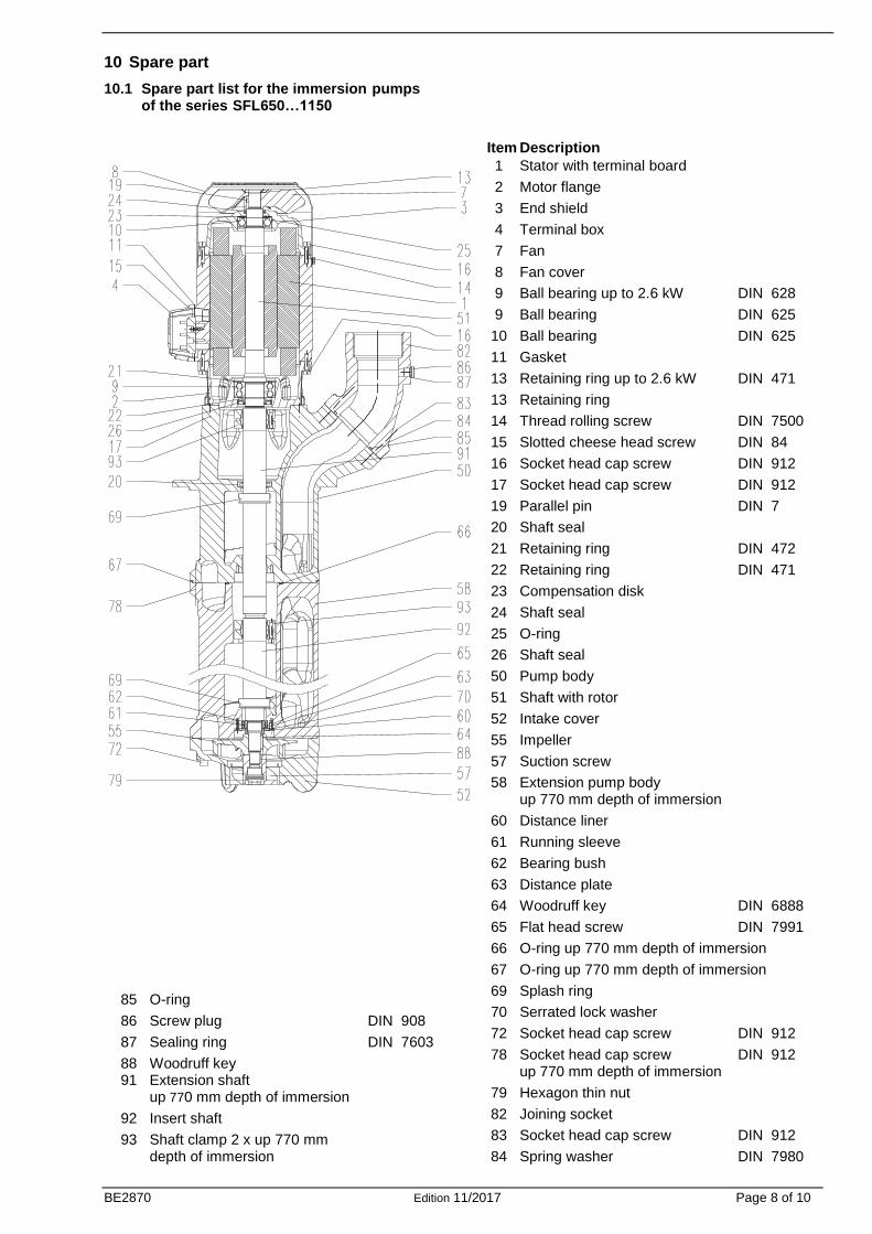
10 Spare part
10.1 Spare part list for the immersion pumps of the series SFL650…1150
Item Description
1 Stator with terminal board
2 Motor flange
3 End shield
4 Terminal box
7 Fan
8 Fan cover
9 Ball bearing up to 2.6 kW DIN 628
9 Ball bearing DIN 625
10 Ball bearing DIN 625
11 Gasket
13 Retaining ring up to 2.6 kW DIN 471
13 Retaining ring
14 Thread rolling screw DIN 7500
15 Slotted cheese head screw DIN 84
16 Socket head cap screw DIN 912
17 Socket head cap screw DIN 912
19 Parallel pin DIN 7
20 Shaft seal
21 Retaining ring DIN 472
22 Retaining ring DIN 471
23 Compensation disk
24 Shaft seal
25 O-ring
26 Shaft seal
50 Pump body
51 Shaft with rotor
52 Intake cover
55 Impeller
57 Suction screw
58 Extension pump body up 770 mm depth of immersion
60 Distance liner
61 Running sleeve
62 Bearing bush
63 Distance plate
64 Woodruff key DIN 6888
65 Flat head screw DIN 7991
66 O-ring up 770 mm depth of immersion
67 O-ring up 770 mm depth of immersion
69 Splash ring
70 Serrated lock washer
72 Socket head cap screw DIN 912
78 Socket head cap screw DIN 912 up 770 mm depth of immersion
79 Hexagon thin nut
82 Joining socket
83 Socket head cap screw DIN 912
84 Spring washer DIN 7980
85 O-ring
86 Screw plug DIN 908
87 Sealing ring DIN 7603
88 Woodruff key 91 Extension shaft up 770 mm depth of immersion
92 Insert shaft
93 Shaft clamp 2 x up 770 mm depth of immersion
BE2870 Edition 11/2017 Page 9 of 10
10.2 Indications to the spare part order
Spare parts are available from the supplier. Standard commercially available parts are to be purchased in accordance with the model type. The ordering of spare parts should contain the following details:
1. Pumptype e.g. SFL850 / 330
2. Pump No. e.g. 04152870 The date of the construction year is a compo-nent of the pumps type number.
3. Voltage, Frequency and Power Take item 1, 2 and 3 from the nameplate
4. Spare part with item No. e.g. Intake cover item No. 52
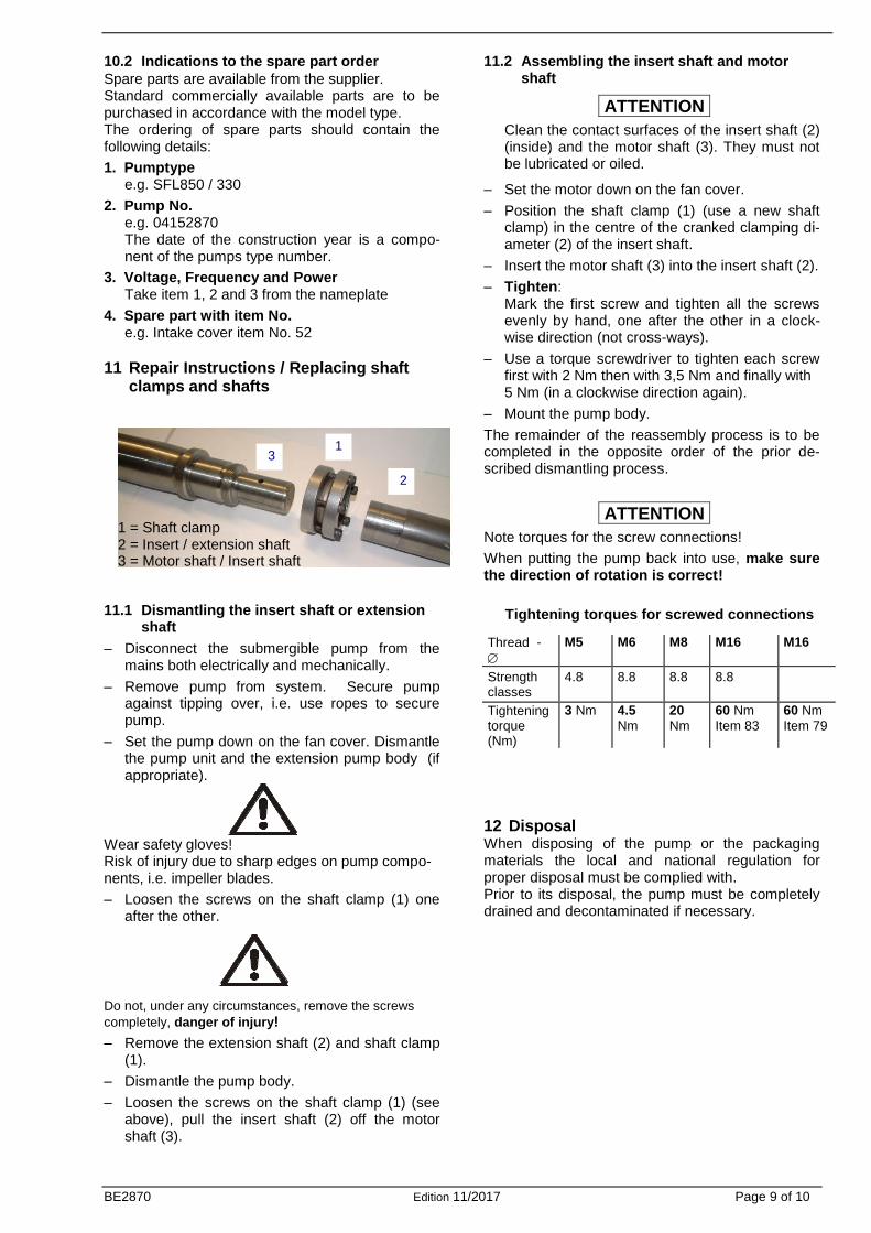
11 Repair Instructions / Replacing shaft clamps and shafts
11.1 Dismantling the insert shaft or extension shaft
– Disconnect the submergible pump from the mains both electrically and mechanically.
– Remove pump from system. Secure pump against tipping over, i.e. use ropes to secure pump.
– Set the pump down on the fan cover. Dismantle the pump unit and the extension pump body (if appropriate).
Wear safety gloves! Risk of injury due to sharp edges on pump compo-nents, i.e. impeller blades.
– Loosen the screws on the shaft clamp (1) one after the other.
Do not, under any circumstances, remove the screws
completely, danger of injury!
– Remove the extension shaft (2) and shaft clamp (1).
– Dismantle the pump body.
– Loosen the screws on the shaft clamp (1) (see above), pull the insert shaft (2) off the motor shaft (3).
11.2 Assembling the insert shaft and motor shaft
ATTENTION
Clean the contact surfaces of the insert shaft (2) (inside) and the motor shaft (3). They must not be lubricated or oiled.
– Set the motor down on the fan cover.
– Position the shaft clamp (1) (use a new shaft clamp) in the centre of the cranked clamping di-ameter (2) of the insert shaft.
– Insert the motor shaft (3) into the insert shaft (2).
– Tighten: Mark the first screw and tighten all the screws evenly by hand, one after the other in a clock-wise direction (not cross-ways).
– Use a torque screwdriver to tighten each screw first with 2 Nm then with 3,5 Nm and finally with 5 Nm (in a clockwise direction again).
– Mount the pump body.
The remainder of the reassembly process is to be completed in the opposite order of the prior de-scribed dismantling process.
ATTENTION
Note torques for the screw connections!
When putting the pump back into use, make sure the direction of rotation is correct!
12 Disposal When disposing of the pump or the packaging materials the local and national regulation for proper disposal must be complied with. Prior to its disposal, the pump must be completely drained and decontaminated if necessary.
Thread -
M5 M6 M8 M16 M16
Strength classes
4.8 8.8 8.8 8.8
Tightening torque (Nm)
3 Nm 4.5
Nm
20
Nm
60 Nm
Item 83
60 Nm
Item 79
Tightening torques for screwed connections
3 1
2
1 = Shaft clamp 2 = Insert / extension shaft 3 = Motor shaft / Insert shaft
BE2870 Edition 11/2017 Page 10 of 10
13 EC declaration of conformity
DEUTSCH / ENGLISH /FRANÇAIS / ESPAÑOL
EG-Konformitätserklärung
EC declaration of conformity / Déclaration de conformité CE / Declaración de conformidad CE
Hersteller / Manufacturer / Constructeur / Fabricante
Brinkmann Pumpen, K. H. Brinkmann GmbH & Co. KG Friedrichstraße 2, D-58791 Werdohl
Produktbezeichnung / Product name / Désignation du produit / Designación del producto
Tauchpumpen / Immersion pumps / Pompes plongeantes / Bombas de inmersión
Typ / Type / Tipo SFL650…1150
Das bezeichnete Produkt stimmt mit den folgenden Richtlinien des Rates zur Angleichung der Rechtsvorschriften der EG-Mitgliedsstaaten überein: The named product conforms to the following Council Directives on approximation of laws of the EEC Member States: Le produit sus-mentionné est conforme aux Directives du Conseil concernant le rapprochement des législations des Etats membres CEE: El producto designado cumple con las Directivas del Consejo relativas a la aproximación de las legislaciones de los Estados Miembros de la CEE:
2006/42/EG Richtlinie für Maschinen
2006/42/EC Council Directive for machinery
2006/42/CE Directive du Conseil pour les machines
2006/42/CE Directivas del Consejo para máquinas
2014/30/EU Richtlinie für elektromagnetische Verträglichkeit
2014/30/EU Council Directive for Electromagnetic compatibility
2014/30/UE Directive du Conseil pour Compatibilité électromagnétique
2014/30/UE Directivas del Consejo para Compatibilidad electromagnética
Hinsichtlich der elektrischen Gefahren wurden gemäß Anhang I Nr. 1.5.1 der Maschinenrichtlinie 2006/42/EG die Schutz-ziele der Niederspannungsrichtlinie 2014/35/EU eingehalten.
With respect to potential electrical hazards as stated in appendix І No. 1.5.1 of the machine guide lines 2006/42/EC all safety protection goals are met according to the low voltage guide lines 2014/35/EU.
Conformément à l'annexe I N° 1.5.1 de la Directive "Machines" (2006/42/CE) les objectifs de sécurité relatifs au matériel électrique de la Directive "Basse Tension" 2014/35/UE ont été respectés.
Con respecto al potencial peligro eléctrico como se indica en el apéndice I No. 1.5.1 del manual de la máquina 2006/42/CE, todos los medios de protección de seguridad se encuentran según la guía de bajo voltaje 2014/35/UE..
Die Übereinstimmung mit den Vorschriften dieser Richtlinien wird nachgewiesen durch die vollständige Einhaltung folgen-der Normen: Conformity with the requirements of this Directives is testified by complete adherence to the following standards:
La conformité aux prescriptions de ces Directives est démontrée par la conformité intégrale avec les normes suivantes:
La conformidad con las prescripciones de estas directivas queda justificada por haber cumplido totalmente las siguientes normas:
Harmonisierte Europ. Normen / Harmonised Europ. Standards / Normes europ. harmonisées / Normas europ. armoniza-das
EN 809 :1998+A1 :2009+AC :2010 EN ISO 12100 :2010 EN 60204-1 :2006/AC :2010 EN 61000-3-2 :2006/A2 :2009 EN 61000-3-3 :2013 EN 61000-6-2 :2005/AC :2005 EN 61000-6-3 :2007/A1 :2011/AC :2012
Nationale Normen / National Standards / Normes nationales / Normas nacionales : EN 60034-1 :2010/AC :2010
Die Hinweise in der Betriebsanleitung für den Einbau und die Inbetriebnahme der Pumpe sind zu beachten.
The instructions contained in the operating manual for installation and start up the pump have to be followed.
Les indications d’installation / montage et de mise en service de la pompe prévues dans l’instruction d’emploi doivent être suivies.
Tenga en cuenta las instrucciones en el manual para la instalación y puesta en marcha de la bomba.
Brinkmann Pumpen, K. H. Brinkmann GmbH & Co. KG
Werdohl, 27.11.2017
...............................................................................................
Norbert Burkl Leiter Qualitätsmanagement / Manager of quality management / Directeur de gestion de la qualité / Director de gestión de calidad
Dr. H. Abou Dayé
K. H. Brinkmann GmbH & Co. KG Friedrichstraße 2, D-58791 Werdohl
Dokumentationsbevollmächtigter / Representative of documentation/ Mandataire de documentation / Mandatario de documentación