Embed Size (px)
Citation preview
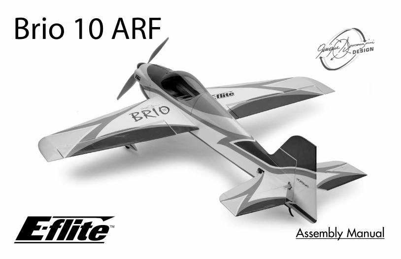
Brio 10 ARF
Assembly Manual
2
Table of Contents
Landing Gear Installation ..................................11Aileron Hinging ...............................................15Aileron Servos and Linkages ..............................18Wing Installation ..............................................21Stabilizer, Elevator & Rudder .............................23Firewall Installation ...........................................28Park 480 Outrunner Motor Installation ................30Power 10 Outrunner Motor Installation ...............326-Pole Motor Installation ....................................34Cowling, ESC and Propeller Installation ..............36Rudder and Elevator Servos ...............................43Final Assembly .................................................49Control Throws .................................................51Center of Gravity .............................................52Notes: .............................................................532005 Official AMA National Model Aircraft Safety Code .......54
Contents of Kit/Parts Layout .................................3Introduction .......................................................4Specifications ....................................................4Required Radio Equipment ..................................4Important Information About Motor Selection .........5Quique Somenzini’s Lightweight 3D Power Setup ...5High Speed Precision Outrunner Setup .................5High Power 6-Pole Setup (Using Gearbox)* ..........6Required Tools and Adhesives ..............................6Optional Accessories ..........................................6Using the Manual ...............................................7Warning ...........................................................7Before Starting Assembly.....................................7Note on Lithium Polymer Batteries ........................7Limited Warranty Period ......................................7Safety Precautions ..............................................8Questions, Assistance, and Repairs ......................8Questions or Assistance ......................................8Inspection or Repairs ..........................................8Limited Warranty & Limits of Liability ....................9Warranty Inspection and Repairs .......................10Non-Warranty Repairs ......................................10
3
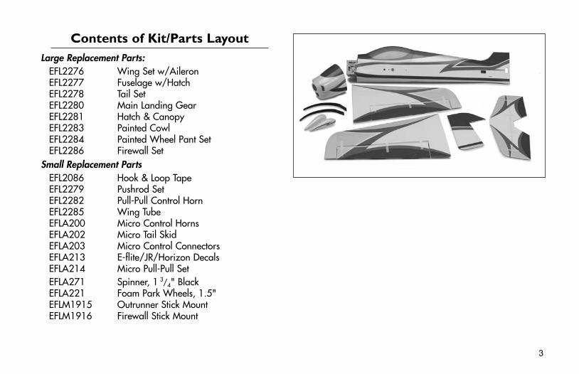
Contents of Kit/Parts LayoutLarge Replacement Parts:
EFL2276 Wing Set w/AileronEFL2277 Fuselage w/HatchEFL2278 Tail SetEFL2280 Main Landing GearEFL2281 Hatch & CanopyEFL2283 Painted CowlEFL2284 Painted Wheel Pant SetEFL2286 Firewall Set
Small Replacement PartsEFL2086 Hook & Loop TapeEFL2279 Pushrod SetEFL2282 Pull-Pull Control HornEFL2285 Wing TubeEFLA200 Micro Control HornsEFLA202 Micro Tail SkidEFLA203 Micro Control ConnectorsEFLA213 E-flite/JR/Horizon DecalsEFLA214 Micro Pull-Pull SetEFLA271 Spinner, 1
3/4" BlackEFLA221 Foam Park Wheels, 1.5"EFLM1915 Outrunner Stick MountEFLM1916 Firewall Stick Mount
4
Introduction
Thank you for purchasing the E-flite™ Brio 10 ARF. If anybody knows what precision feels like, 3-time World Champion and 2-time US Champion Quique Somenzini certainly does. And he has poured all this experience into the design of the Brio 10—a 10-size replica of the same F3A plane he used to win the 2005 US Nats. At the heart of its performance is a low aspect ratio wing that moves the center of lift closer to the fuselage. The result is an electric pattern plane with outstanding roll rates and a locked-in feel that will give you the confidence to fly artistic aerobatics with absolute precision.
SpecificationsWingspan: 41 in (1040mm)Length: 40 in (1015mm)Wing Area: 325 sq in (21 sq dm)Weight w/o Battery: 25–29 oz (710–820g)Weight w/ Battery: 28–34 oz (795–965g)
Required Radio Equipment
You will need a minimum 6-channel transmitter (for proper mixing capabilities), crystal, and four sub-micro servos. You can choose to purchase a complete radio system that includes all of these items or, if you are using an existing transmitter, just purchase the other required equipment separately. JR’s XP9303 has every possible programming feature a precision plane like the Brio 10 would need. This, combined with a feather-light JR 610UL, is the same system Quique uses in his Brio 10.
Quique’s Transmitter JR 9303 XP9303 9-Channel, 30-Model
Memory TransmitterPurchase Separately
JSP30610 6-Channel UltraLite Rx w/o Crystal, Positive Shift JR/Air (72 MHz)
Or
JSP30615 6-Channel UltraLite Rx w/o Crystal, Negative Shift Fut/HRC (72 MHz)
JRPXFR** FM Receiver CrystalEFLRS75 7.5 Gram Sub-Micro Servo (4)JSP98110 6" Servo Extension (2)JSP98030 12" Servo Extension

5
Important Information About Motor Selection
The Brio 10 has two firewall options that are designed to easily utilize our recommended E-flite™ Park 480 BL Outrunner Motor, 1020Kv, the optional Power 10 BL Outrunner Motor, 1100Kv or our optional Six-Series BL 2700Kv Motor (28mm) with a gearbox. First determine what power system you will be using, an outrunner or 6-pole inrunner with a gearbox. You can also use the included Firewall Stick Mount and easily mount our Six-Series with a gearbox, or even our Park 480 Outrunner when you use the included Outrunner Stick Mount. By using the included outrunner standoffs, mounting a Power 10 Outrunner is also very easy.If it's Quique Somenzini's lightweight setup you are looking for, try using our park 480 Outrunner, 1020 Kv motor (EFLM1505). For high-speed F3A flying only, we recommend E-flite’s Power 10 BL Outrunner motor (EFLM4010A). This setup will weigh about 3 ounces more than the lightweight alternative.For a geared alternative with strong vertical power and speed, try the Six-Series BL 2700Kv Motor (28mm) (EFLM2005).
Best Recommended SetupEFLM1505 Park 480 BL Outrunner Motor, 1020KvEFLA312B 40-Amp Brushless ESC (V2)APC11070E Electric Propeller, 11 x 7E WSD1300 Ultra Plug, Male/Female SetEFLC3005 Celectra 1–3 Cell Li-Po Charger
Recommended Battery (by E-flite)THP13203SPL 1320mAh 3-Cell 11.1V Li-Po, 16GA
This is the lightweight setup Quique flies and recommends. This is the best setup for precision flying, artistic aerobatic flying, and 3D.
Note: The use of the Thunder Power 11.1V 1320mAh pack with wide open throttle will discharge the battery at a very high rate. Proper throttle management is required to achieve optimum performance and prevent shortened battery life.
6
Required Tools and AdhesivesTools & Equipment
EFLA257 Screwdriver, #0 Phillips (or included with EFLA250)
EFLA251 Hex Wrench: 3/32" (or included with EFLA250)
7mm nut driverHobby knifePaper towel/tissueSquareRulerFelt-tipped penString
AdhesivesMedium CA Thick CA6-Minute Epoxy, 9oz (HAN8000)Threadlock (for mounting motor to gearbox)
Optional AccessoriesEFLA110 Power MeterEFLA212 Gear Puller: 1mm–5mm Shaft
Other Possible SetupsOptional High Speed Precision Outrunner Setup
EFLM4010A Power 10 Brushless Outrunner Motor, 1100Kv
EFLA312B 40-Amp Brushless ESC (V2)APC12060E Electric Propeller, 12 x 6E THP21003SPL 2100mAh 3-Cell 11.1V Li-Po, 16GAWSD1300 Ultra Plug, Male/Female SetEFLC3005 Celectra 1–3 Cell Li-Po Charger
This setup is for high speed F3A. It is not recommended for 3D flying.
Optional High Power 6-Pole Setup (Using Gearbox)EFLM2005 Six-Series BL 2700Kv Motor (28mm) EFLM236 400 Gearbox w/56T 0.5M Spur GearEFLM1957 19T 0.5 Module 3.2mm ID Pinion GearEFLA312B 40-Amp Brushless ESC (V2)APC12060E Electric Propeller, 12 x 6E THP21003SPL 2100mAh 3-Cell 11.1V Li-Po, 16GAWSD1300 Ultra Plug, Male/Female SetEFLC3005 Celectra 1–3 Cell Li-Po Charger
Using this setup will give you plenty of power for extreme F3A precision aerobatic flights and 3D aerobatics.
7
Using the Manual
This manual is divided into sections to help make assembly easier to understand, and to provide breaks between each major section. In addition, check boxes have been placed next to each step to keep track of each step completed. Steps with a single circle () are performed once, while steps with two circles ( ) indicate that the step will require repeating, such as for a right or left wing panel, two servos, etc.Remember to take your time and follow the directions.
Warning
An RC aircraft is not a toy! If misused, it can cause serious bodily harm and damage to property. Fly only in open areas, preferably at AMA (Academy of Model Aeronautics) approved flying sites, following all instructions included with your radio.Keep loose items that can get entangled in the propeller away from the prop, including loose clothing, or other objects such as pencils and screwdrivers. Especially keep your hands away from the propeller.
Before Starting Assembly
Before beginning the assembly of your Brio 10, remove each part from its bag for inspection. Closely inspect the fuselage, wing panels, rudder and stabilizer for damage. If you find any damaged or missing parts, contact the place of purchase.
Note on Lithium Polymer BatteriesLithium Polymer batteries are significantly more volatile than alkaline or Ni-Cd/Ni-MH batteries used in RC applications. All manufacturer’s instructions and warnings must be followed closely. Mishandling of Li-Po batteries can result in fire. Always follow the manufacturer’s instructions when disposing of Lithium Polymer batteries.
Limited Warranty PeriodHorizon Hobby, Inc. guarantees this product to be free from defects in both material and workmanship at the date of purchase.
Questions or AssistanceFor questions or assistance, please direct your email to [email protected], or call 877.504.0233 toll free to speak to a service technician.
Inspection or RepairsIf your product needs to be inspected or repaired, please call for a Return Merchandise Authorization (RMA). Pack the product securely using a shipping carton. Please note that original boxes may be included, but are not designed to withstand the rigors of shipping without additional protection. Ship via a carrier that provides tracking and insurance for lost or damaged parcels, as Horizon Hobby, Inc. is not responsible for merchandise until it arrives and is accepted at our facility. Include your complete name, address, phone number where you can be reached during business days, RMA number, and a brief summary of the problem. Be sure your name, address, and RMA number are clearly written on the shipping carton.
Safety PrecautionsThis is a sophisticated hobby product and not a toy. It must be operated with caution and common sense and requires some basic mechanical ability. Failure to operate this product in a safe and responsible manner could result in injury or damage to the product or other property. This product is not intended for use by children without direct adult supervision.The product manual contains instructions for safety, operation and maintenance. It is essential to read and follow all the instructions and warnings in the manual, prior to assembly, setup or use, in order to operate correctly and avoid damage or injury.
Questions, Assistance, and RepairsYour local hobby store and/or place of purchase cannot provide warranty support or repair. Once assembly, setup or use of the product has been started, you must contact Horizon Hobby, Inc. directly. This will enable Horizon to better answer your questions and service you in the event that you may need any assistance.
8
Pursuant to this Limited Warranty, Horizon Hobby, Inc. will, at its option, (i) repair or (ii) replace, any product determined by Horizon Hobby, Inc. to be defective. In the event of a defect, these are your exclusive remedies.This warranty does not cover cosmetic damage or damage due to acts of God, accident, misuse, abuse, negligence, commercial use, or modification of or to any part of the product. This warranty does not cover damage due to improper installation, operation, maintenance, or attempted repair by anyone other than an authorized Horizon Hobby, Inc. service center. This warranty is limited to the original purchaser and is not transferable. In no case shall Horizon Hobby’s liability exceed the original cost of the purchased product and will not cover consequential, incidental or collateral damage. Horizon Hobby, Inc. reserves the right to inspect any and all equipment involved in a warranty claim. Repair or replacement decisions are at the sole discretion of Horizon Hobby, Inc. Further, Horizon Hobby reserves the right to change or modify this warranty without notice.
REPAIR OR REPLACEMENT AS PROVIDED UNDER THIS WARRANTY IS THE EXCLUSIVE REMEDY OF THE CONSUMER. HORIZON HOBBY, INC. SHALL NOT BE LIABLE FOR ANY INCIDENTAL OR CONSEQUENTIAL DAMAGES.As Horizon Hobby, Inc. has no control over use, setup, final assembly, modification or misuse, no liability shall be assumed nor accepted for any resulting damage or injury. By the act of use, setup or assembly, the user accepts all resulting liability.If you as the purchaser or user are not prepared to accept the liability associated with the use of this product, you are advised to return this product immediately in new and unused condition to the place of purchase.
Limited Warranty & Limits of Liability
9
Warranty Inspection and RepairsTo receive warranty service, you must include your original sales receipt verifying the proof-of-purchase date. Providing warranty conditions have been met, your product will be repaired or replaced free of charge. Repair or replacement decisions are at the sole discretion of Horizon Hobby.
Non-Warranty RepairsShould your repair not be covered by warranty and the expense exceeds 50% of the retail purchase cost, you will be provided with an estimate advising you of your options. You will be billed for any return freight for non-warranty repairs. Please advise us of your preferred method of payment. Horizon Hobby accepts money orders and cashiers checks, as well as Visa, MasterCard, American Express, and Discover cards. If you choose to pay by credit card, please include your credit card number and expiration date. Any repair left unpaid or unclaimed after 90 days will be considered abandoned and will be disposed of accordingly.Electronics and engines requiring inspection or repair should be shipped to the following address (freight prepaid):
Horizon Service Center 4105 Fieldstone Road
Champaign, Illinois 61822All other products requiring inspection or repair should be shipped to the following address (freight prepaid):
Horizon Product Support 4105 Fieldstone Road
Champaign, Illinois 61822
10
Landing Gear InstallationRequired Parts
• Fuselage • Main landing gear (L&R)• Tail skid • Wheel pant (L&R)• 2mm nut (6) • #4 washer (4)• 1
3/8" (35mm) wheel (2)• 2mm x 25mm screw (2)• 4-40 x 1/2" socket screw (4)• 2mm x 8mm wood screw (2)
Required Tools and Adhesives• Threadlock • Drill bit: 1/8" (3mm)• Drill • Medium CA• Hobby knife • Hex wrench: 3/32"• Thin CA• Phillips screwdriver (small)
Note: You may consider using a larger diameter wheel, such as 2
1/4" (58mm), if your flying site has rough terrain. By using a larger wheel, you will not be able to use the included wheel pants.
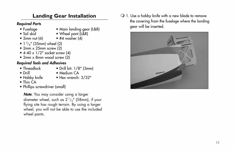
1. Use a hobby knife with a new blade to remove the covering from the fuselage where the landing gear will be inserted.
11
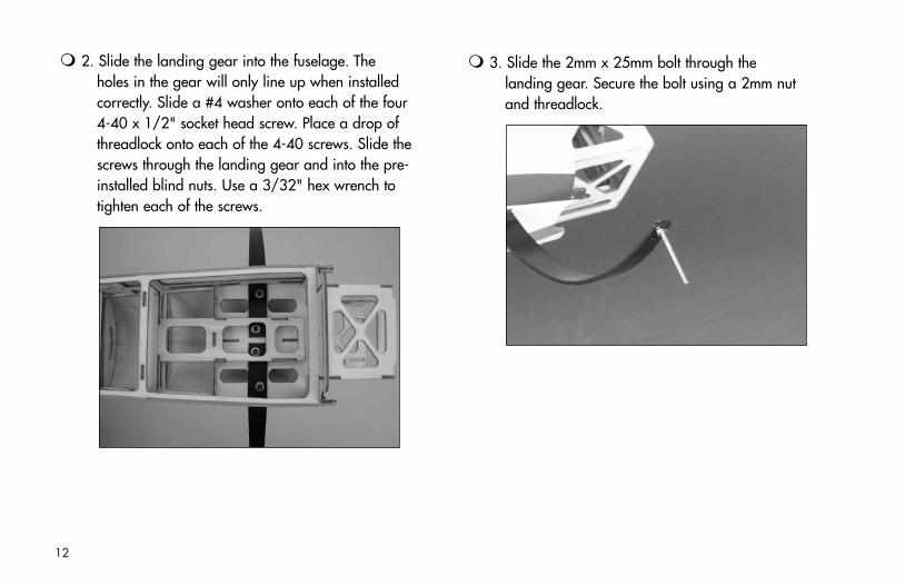
3. Slide the 2mm x 25mm bolt through the landing gear. Secure the bolt using a 2mm nut and threadlock.
2. Slide the landing gear into the fuselage. The holes in the gear will only line up when installed correctly. Slide a #4 washer onto each of the four 4-40 x 1/2" socket head screw. Place a drop of threadlock onto each of the 4-40 screws. Slide the screws through the landing gear and into the pre-installed blind nuts. Use a 3/32" hex wrench to tighten each of the screws.
12
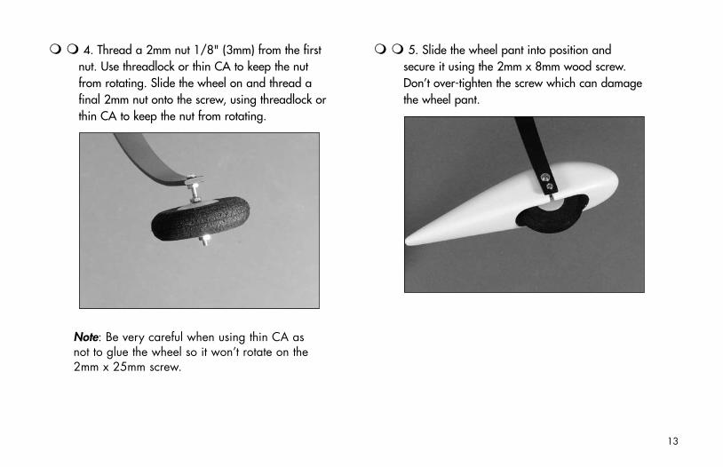
4. Thread a 2mm nut 1/8" (3mm) from the first nut. Use threadlock or thin CA to keep the nut from rotating. Slide the wheel on and thread a final 2mm nut onto the screw, using threadlock or thin CA to keep the nut from rotating.
Note: Be very careful when using thin CA as not to glue the wheel so it won’t rotate on the 2mm x 25mm screw.
5. Slide the wheel pant into position and secure it using the 2mm x 8mm wood screw. Don’t over-tighten the screw which can damage the wheel pant.
13
6. Repeat Steps 4 through 6 for the remaining wheel and wheel pant.
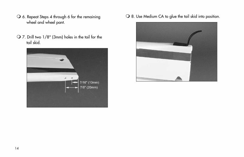
7. Drill two 1/8" (3mm) holes in the tail for the tail skid.
8. Use Medium CA to glue the tail skid into position.
14
Aileron HingingRequired Parts
• Wing (left and right)• Aileron (left and right)• CA hinges (6)
Required Tools and Adhesives• T-pins • Thin CA• Drill • Paper towel• Drill bit: 1/16" (2mm)
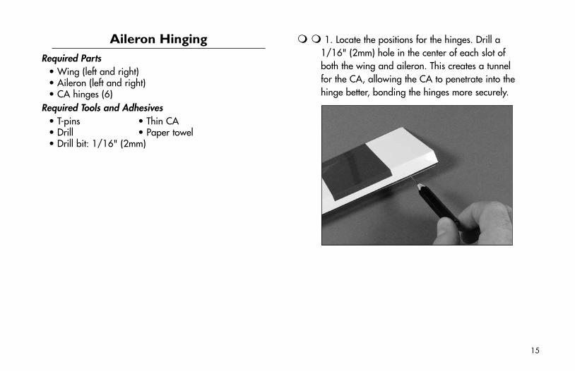
1. Locate the positions for the hinges. Drill a 1/16" (2mm) hole in the center of each slot of both the wing and aileron. This creates a tunnel for the CA, allowing the CA to penetrate into the hinge better, bonding the hinges more securely.
15
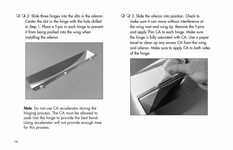
3. Slide the aileron into position. Check to make sure it can move without interference at the wing root and wing tip. Remove the T-pins and apply Thin CA to each hinge. Make sure the hinge is fully saturated with CA. Use a paper towel to clean up any excess CA from the wing and aileron. Make sure to apply CA to both sides of the hinge.
2. Slide three hinges into the slits in the aileron. Center the slot in the hinge with the hole drilled in Step 1. Place a T-pin in each hinge to prevent it from being pushed into the wing when installing the aileron.
Note: Do not use CA accelerator during the hinging process. The CA must be allowed to soak into the hinge to provide the best bond. Using accelerator will not provide enough time for this process.
16
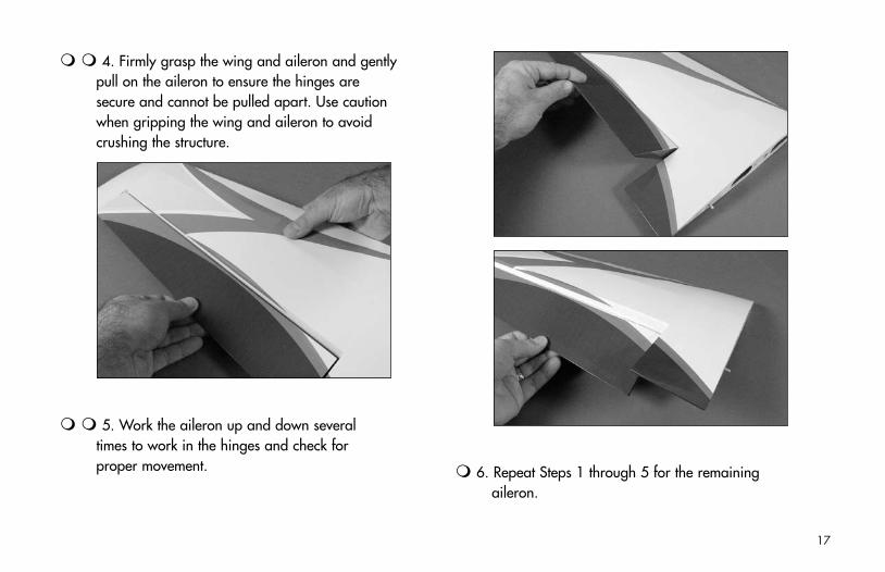
4. Firmly grasp the wing and aileron and gently pull on the aileron to ensure the hinges are secure and cannot be pulled apart. Use caution when gripping the wing and aileron to avoid crushing the structure.
5. Work the aileron up and down several times to work in the hinges and check for proper movement. 6. Repeat Steps 1 through 5 for the remaining
aileron.
17
Aileron Servos and LinkagesRequired Parts
• Wing panel (right and left)• Micro control connector (2)• 2mm x 4mm screw (2)• Sub-Micro Servo (2)• 3" (75mm) pushrod (2)• Control horn and backplate (2)• 6" (150mm) servo extension (2)
Required Tools and Adhesives• Hobby knife • 6-minute epoxy• String • Phillips screwdriver (small)
1. Use 6-minute epoxy to attach the control horn to the aileron. Make sure the horn is fully seated in the opening.
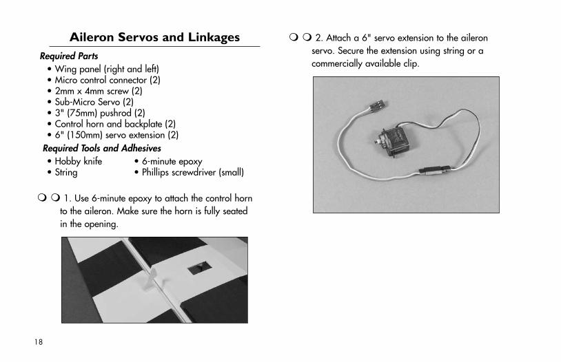
2. Attach a 6" servo extension to the aileron servo. Secure the extension using string or a commercially available clip.
18
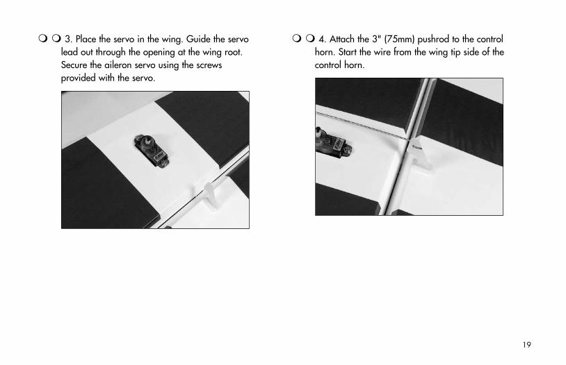
3. Place the servo in the wing. Guide the servo lead out through the opening at the wing root. Secure the aileron servo using the screws provided with the servo.
4. Attach the 3" (75mm) pushrod to the control horn. Start the wire from the wing tip side of the control horn.
19
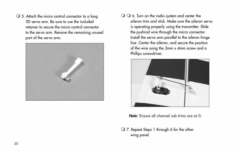
5. Attach the micro control connector to a long 3D servo arm. Be sure to use the included retainer to secure the micro control connector to the servo arm. Remove the remaining unused part of the servo arm.
6. Turn on the radio system and center the aileron trim and stick. Make sure the aileron servo is operating properly using the transmitter. Slide the pushrod wire through the micro connector. Install the servo arm parallel to the aileron hinge line. Center the aileron, and secure the position of the wire using the 2mm x 4mm screw and a Phillips screwdriver.
Note: Ensure all channel sub trims are at 0.
7. Repeat Steps 1 through 6 for the other wing panel.
20
Wing InstallationRequired Parts
• Fuselage • Wing (right and left)• Wing tube • #4 washer (2)• 4-40 x 1/2" socket head screw (2)
Required Tools and Adhesives• Hex wrench: 3/32"
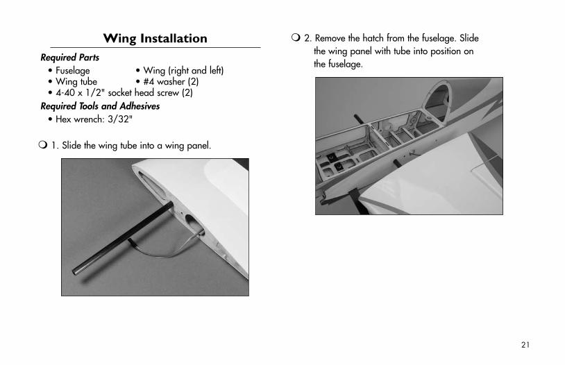
1. Slide the wing tube into a wing panel.
2. Remove the hatch from the fuselage. Slide the wing panel with tube into position on the fuselage.
21
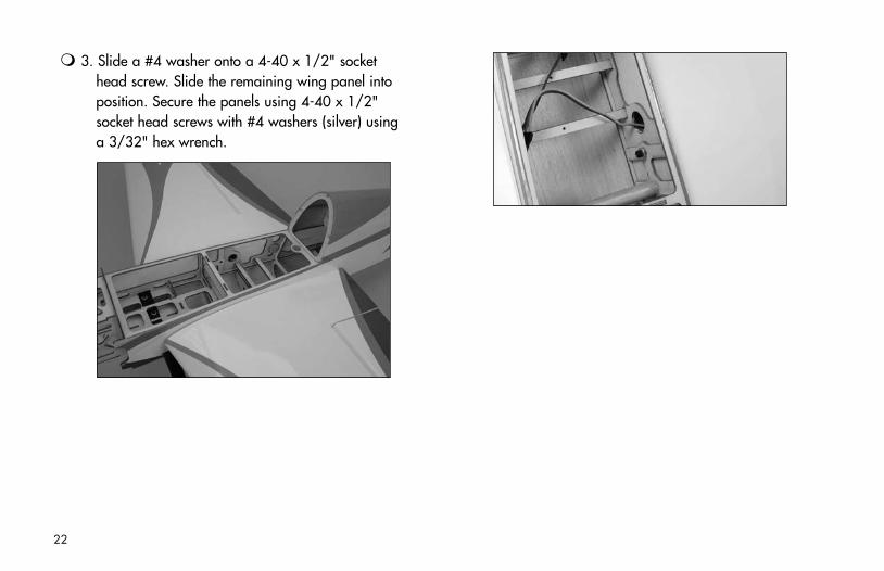
3. Slide a #4 washer onto a 4-40 x 1/2" socket head screw. Slide the remaining wing panel into position. Secure the panels using 4-40 x 1/2" socket head screws with #4 washers (silver) using a 3/32" hex wrench.
22
Stabilizer, Elevator & RudderRequired Parts
• Fuselage w/wing installed• Stabilizer • Rudder• Elevator • CA hinge (9)
Required Tools and Adhesives• Hobby knife • Felt-tipped pen• Ruler • T-pins• Thin CA • Hobby knife
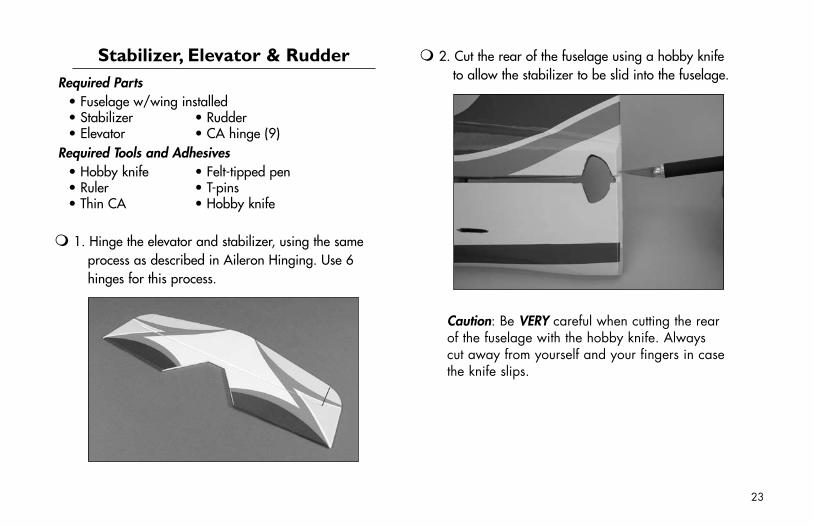
1. Hinge the elevator and stabilizer, using the same process as described in Aileron Hinging. Use 6 hinges for this process.
2. Cut the rear of the fuselage using a hobby knife to allow the stabilizer to be slid into the fuselage.
Caution: Be VERY careful when cutting the rear of the fuselage with the hobby knife. Always cut away from yourself and your fingers in case the knife slips.
23
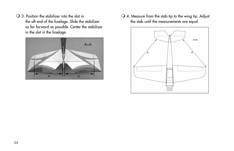
4. Measure from the stab tip to the wing tip. Adjust the stab until the measurements are equal.
A A
A=A
3. Position the stabilizer into the slot in the aft end of the fuselage. Slide the stabilizer as far forward as possible. Center the stabilizer in the slot in the fuselage.
24
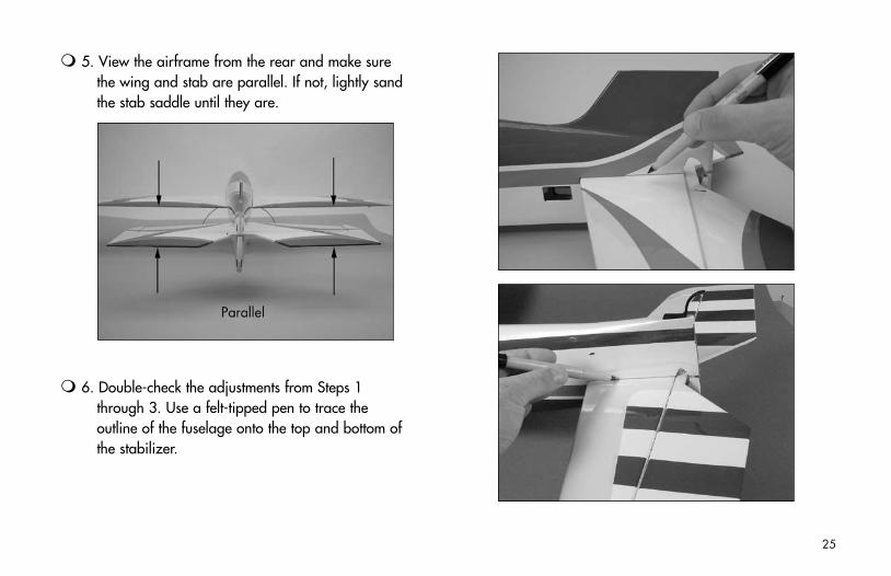
5. View the airframe from the rear and make sure the wing and stab are parallel. If not, lightly sand the stab saddle until they are.
6. Double-check the adjustments from Steps 1 through 3. Use a felt-tipped pen to trace the outline of the fuselage onto the top and bottom of the stabilizer.
25
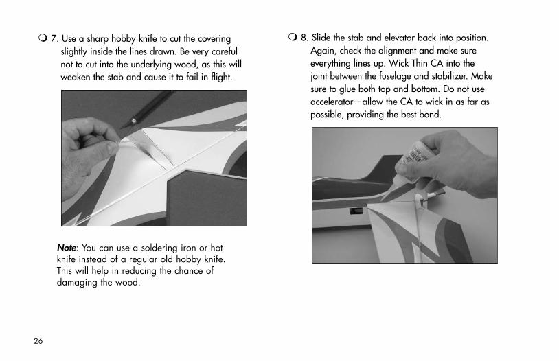
7. Use a sharp hobby knife to cut the covering slightly inside the lines drawn. Be very careful not to cut into the underlying wood, as this will weaken the stab and cause it to fail in flight.
Note: You can use a soldering iron or hot knife instead of a regular old hobby knife. This will help in reducing the chance of damaging the wood.
8. Slide the stab and elevator back into position. Again, check the alignment and make sure everything lines up. Wick Thin CA into the joint between the fuselage and stabilizer. Make sure to glue both top and bottom. Do not use accelerator—allow the CA to wick in as far as possible, providing the best bond.
26
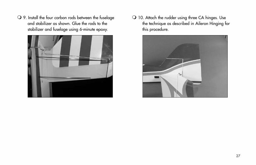
9. Install the four carbon rods between the fuselage and stabilizer as shown. Glue the rods to the stabilizer and fuselage using 6-minute epoxy.
10. Attach the rudder using three CA hinges. Use the technique as described in Aileron Hinging for this procedure.
27
Firewall InstallationRequired Parts
• Fuselage• Power 10 Outrunner FirewallOr• Inrunner/Park 480 Outrunner Firewall
Required Tools and Adhesives• 6-minute epoxy
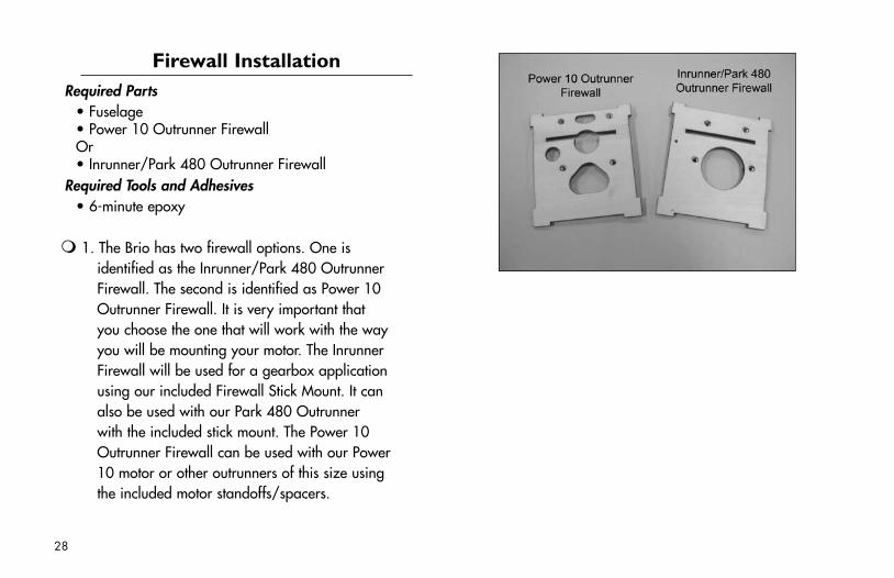
1. The Brio has two firewall options. One is identified as the Inrunner/Park 480 Outrunner Firewall. The second is identified as Power 10 Outrunner Firewall. It is very important that you choose the one that will work with the way you will be mounting your motor. The Inrunner Firewall will be used for a gearbox application using our included Firewall Stick Mount. It can also be used with our Park 480 Outrunner with the included stick mount. The Power 10 Outrunner Firewall can be used with our Power 10 motor or other outrunners of this size using the included motor standoffs/spacers.
28
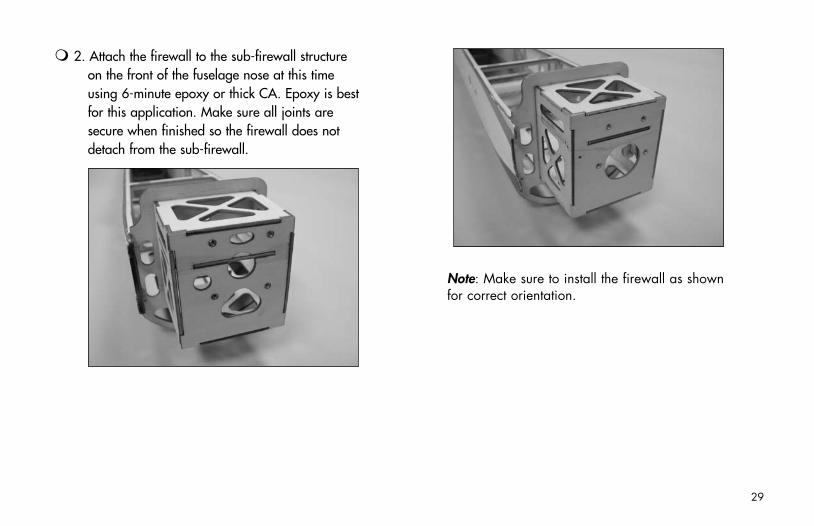
2. Attach the firewall to the sub-firewall structure on the front of the fuselage nose at this time using 6-minute epoxy or thick CA. Epoxy is best for this application. Make sure all joints are secure when finished so the firewall does not detach from the sub-firewall.
Note: Make sure to install the firewall as shown for correct orientation.
29
Park 480 Outrunner Motor InstallationRequired Parts
• Fuselage• Firewall stick mount (included)• 4-40 x 1/2" (12mm) socket head screw (4)• Outrunner stick mount (included)• Aluminum spacers, 4mm long (4)• 3mm x 8mm Phillips head screws (4)
(to mount motor to Outrunner stick mount)• 2mm x 8mm sheet metal screw (3) (to secure mounts)• Park 480-size Brushless Outrunner Motor
Required Tools and Adhesives• Hex wrench: 3/32"• Phillips screwdriver (small)
Skip to page 36 for setup of a 6-pole motor installation using a gearbox.
Note: This section covers the installation of our Park 480 Outrunner or equivalent size motor.
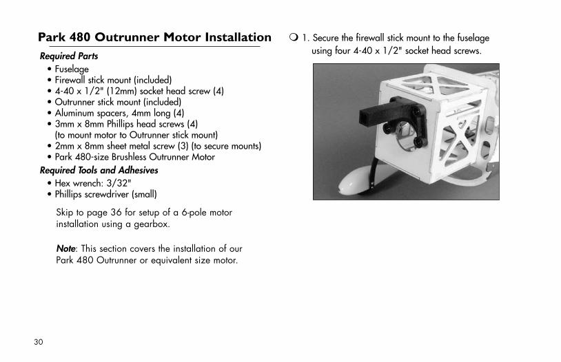
1. Secure the firewall stick mount to the fuselage using four 4-40 x 1/2" socket head screws.
30
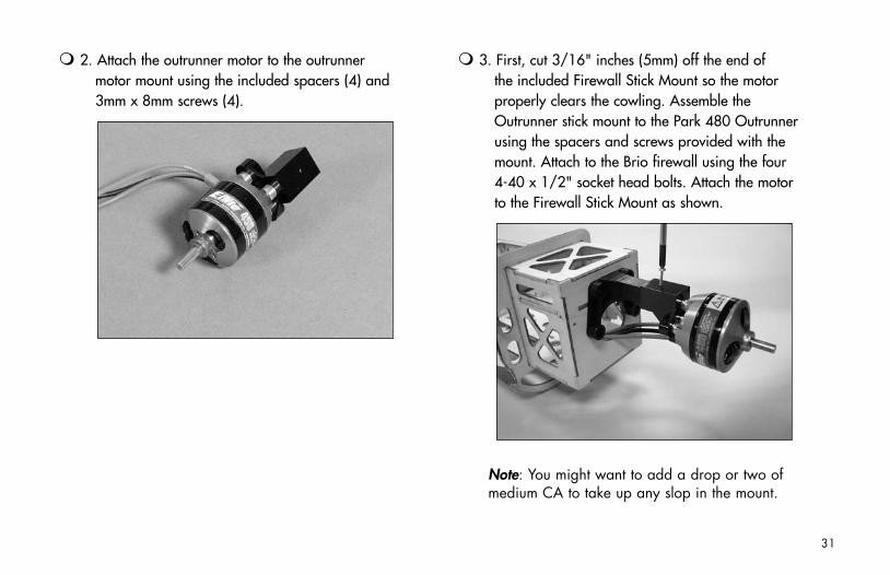
2. Attach the outrunner motor to the outrunner motor mount using the included spacers (4) and 3mm x 8mm screws (4).
3. First, cut 3/16" inches (5mm) off the end of the included Firewall Stick Mount so the motor properly clears the cowling. Assemble the Outrunner stick mount to the Park 480 Outrunner using the spacers and screws provided with the mount. Attach to the Brio firewall using the four 4-40 x 1/2" socket head bolts. Attach the motor to the Firewall Stick Mount as shown.
Note: You might want to add a drop or two of medium CA to take up any slop in the mount.
31
Power 10 Outrunner Motor InstallationRequired Parts
• Fuselage• Outrunner offset mounts, 32mm (4)• 4-40 x 43mm socket head screws (4)• 4-40 washers (4)• Power 10 Brushless Outrunner Motor
Required Tools and Adhesives• Hex wrench: 3/32"
Skip to page 36 for setup of a 6-pole motor installation using a gearbox.
Note: This section covers the installation of our Power 10 Outrunner or equivalent size motor.
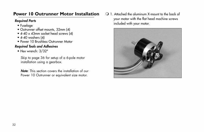
1. Attached the aluminum X-mount to the back of your motor with the flat head machine screws included with your motor.
32
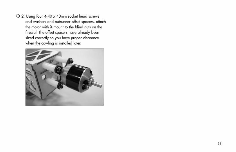
2. Using four 4-40 x 43mm socket head screws and washers and outrunner offset spacers, attach the motor with X-mount to the blind nuts on the firewall The offset spacers have already been sized correctly so you have proper clearance when the cowling is installed later.
33
6-Pole Motor InstallationRequired Parts
• Fuselage• 2mm x 8mm sheet metal screw (3) (to secure mounts)• 4-40 x 1/2" (12mm) socket head screw (4)• Firewall stick mount• 6-Pole motor• 400 Gearbox w/56T 0.5M spur gear• 19T 0.5 Module 3.2mm ID pinion gear
Required Tools and Adhesives• Hex wrench: 3/32"• Phillips screwdriver (small)• Medium CA• Threadlock
Note: This section covers the installation of an inrunner motor and gearbox. Refer back to pages 31 or 34 for outrunner installation.
1. It may be necessary to attach pinion gears or other accessories to your particular motor at this time. Follow instructions included with your motor.
Note: It is very important that the gear mesh is set correctly and is smooth with no binding. The E-flite™ gearbox features adjustable slotted mounting holes to ensure your gear mesh is correct. Remember, if the gear mesh is too loose or too tight it may strip the gears. To extend the life of your gearbox, we also recommend using a small amount of grease, such as lithium grease, on the spur gear.
34
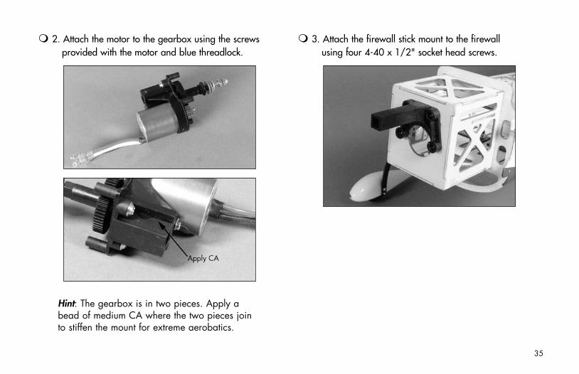
2. Attach the motor to the gearbox using the screws provided with the motor and blue threadlock.
Hint: The gearbox is in two pieces. Apply a bead of medium CA where the two pieces join to stiffen the mount for extreme aerobatics.
3. Attach the firewall stick mount to the firewall using four 4-40 x 1/2" socket head screws.
35
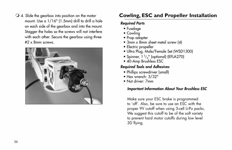
4. Slide the gearbox into position on the motor mount. Use a 1/16" (1.5mm) drill to drill a hole on each side of the gearbox and into the mount. Stagger the holes so the screws will not interfere with each other. Secure the gearbox using three #2 x 8mm screws.
Cowling, ESC and Propeller InstallationRequired Parts
• Fuselage• Cowling• Prop adapter• 3mm x 8mm sheet metal screw (4)• Electric propeller• Ultra Plug, Male/Female Set (WSD1300)• Spinner, 1
3/4" (optional) (EFLA270)• 40-Amp Brushless ESC
Required Tools and Adhesives• Phillips screwdriver (small)• Hex wrench: 3/32"• Nut driver: 7mm
Important Information About Your Brushless ESC
Make sure your ESC brake is programmed to ‘off’. Also, be sure to use an ESC with the proper 9V cutoff when using 3-cell Li-Po packs. We suggest this cutoff to be of the soft variety to prevent hard motor cutoffs during low level 3D flying.
36
Some 35A–40A brushless ESC on the market either warn against running four (4) sub-micro servos or do not specify this setup will work. The reason is because oftentimes running four sub-micro servos with a 3-cell Li-Po battery are outside the range of the controller’s BEC capability. Most controllers on the market can only handle 800mA to 1 Amp continuous draw when using a 3-cell Li-Po battery, some even lower. However, many consumers are still running four sub-micro servos with success. If you choose to attempt this, you must set up your plane properly and check the current draw (under load) of your radio system, making sure it is within the specifications of the controller’s BEC. Be sure to put the ESC in a position to get the best airflow since cooling will help the BEC capacity.
Our E-flite 40A Brushless ESC (V2) (EFLA312B) is equipped with a higher rated, heavy-duty BEC that can dissipate more heat and handle higher wattage when using a 3-cell Li-Po battery. Make sure you specify this part number to ensure you are getting the correct controller. You should always still check your setup first before flying.
Some other alternatives are available:
A. Disable the controller’s BEC per manufacturer’s instructions and use a flight pack battery.
B. Buy a device such as an external BEC that is specified to handle more current.
C. Select a controller such as the Castle Phoenix 35 or our updated E-flite™ 40A Brushless ESC (EFLA312B) that has a higher rated, heavy-duty BEC.
37
1. Connect the ESC to the motor and secure the ESC to the inside of the fuselage using hook and loop material and/or a tie wrap. The location of the ESC may be changed depending on the length of the motor wires, type of ESC and necessity to move the ESC to achieve the correct Center of Gravity.
2. Use the radio system and motor battery to determine the direction of rotation of the propeller. When connected correctly it should rotate counter-clockwise when viewed from the front of the aircraft. If not, follow the directions included with the speed control to correct the direction of rotation.
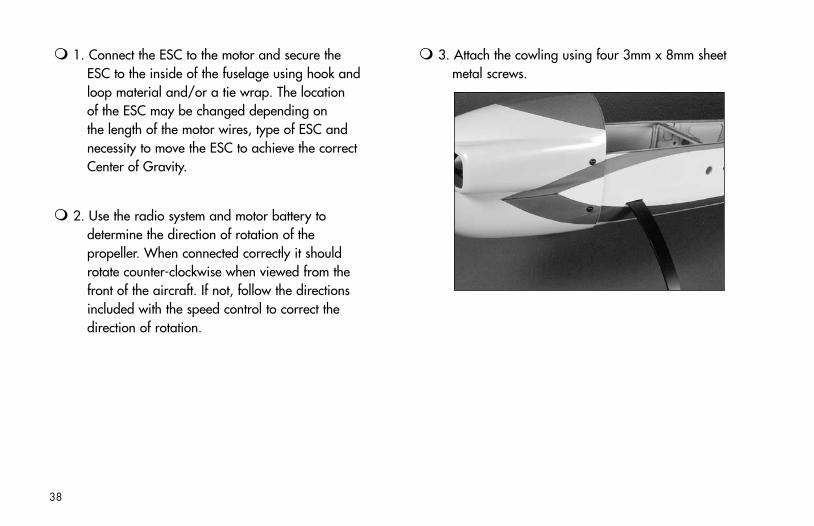
3. Attach the cowling using four 3mm x 8mm sheet metal screws.
38

Note: Steps 4 through 6 cover the installation of the propeller when using an Outrunner motor. Skip to Step 7 for the installation of the propeller when using an Inrunner motor and gearbox.
4. If using an Outrunner motor, it may be necessary to ream a larger opening into the backplate of your E-flite™ spinner to fit the shaft size of the prop adapter shaft. Slide the aluminum prop adapter shaft and collet onto the motor to check the size of the hole in the propeller.
39
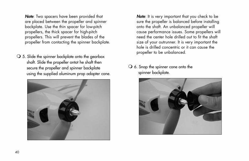
Note: Two spacers have been provided that are placed between the propeller and spinner backplate. Use the thin spacer for low-pitch propellers, the thick spacer for high-pitch propellers. This will prevent the blades of the propeller from contacting the spinner backplate.
5. Slide the spinner backplate onto the gearbox shaft. Slide the propeller ontot he shaft then secure the propeller and spinner backplate using the supplied aluminum prop adapter cone.
Note: It is very important that you check to be sure the propeller is balanced before installing onto the shaft. An unbalanced propeller will cause performance issues. Some propellers will need the center hole drilled out to fit the shaft size of your outrunner. It is very important the hole is drilled concentric or it can cause the propeller to be unbalanced.
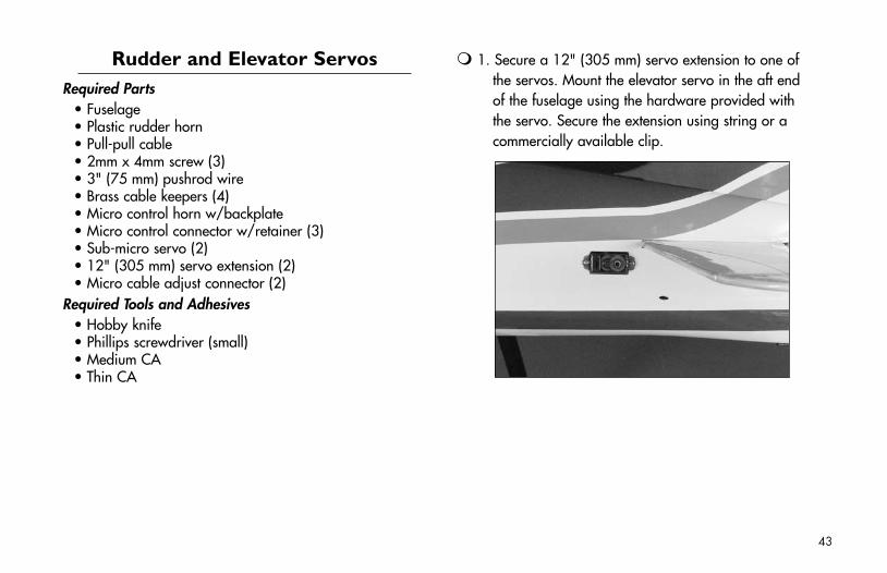
6. Snap the spinner cone onto the spinner backplate.
40
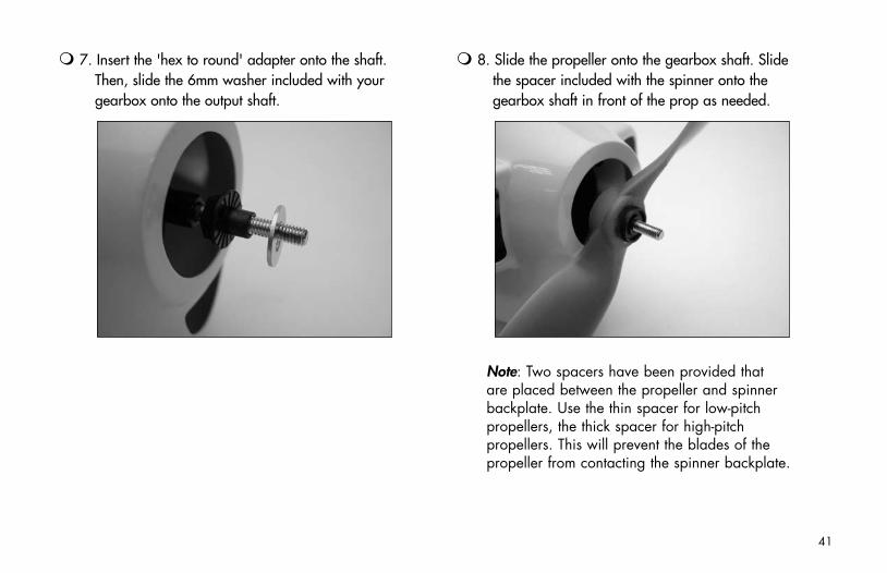
7. Insert the 'hex to round' adapter onto the shaft. Then, slide the 6mm washer included with your gearbox onto the output shaft.
8. Slide the propeller onto the gearbox shaft. Slide the spacer included with the spinner onto the gearbox shaft in front of the prop as needed.
Note: Two spacers have been provided that are placed between the propeller and spinner backplate. Use the thin spacer for low-pitch propellers, the thick spacer for high-pitch propellers. This will prevent the blades of the propeller from contacting the spinner backplate.
41
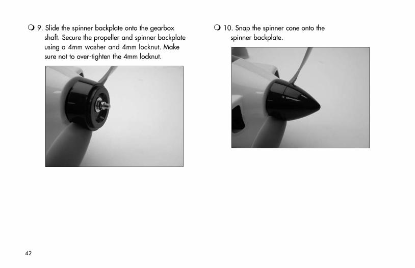
9. Slide the spinner backplate onto the gearbox shaft. Secure the propeller and spinner backplate using a 4mm washer and 4mm locknut. Make sure not to over-tighten the 4mm locknut.
10. Snap the spinner cone onto the spinner backplate.
42
Rudder and Elevator ServosRequired Parts
• Fuselage• Plastic rudder horn• Pull-pull cable• 2mm x 4mm screw (3)• 3" (75 mm) pushrod wire• Brass cable keepers (4)• Micro control horn w/backplate• Micro control connector w/retainer (3)• Sub-micro servo (2)• 12" (305 mm) servo extension (2)• Micro cable adjust connector (2)
Required Tools and Adhesives• Hobby knife• Phillips screwdriver (small)• Medium CA• Thin CA
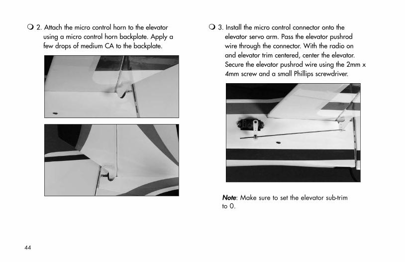
1. Secure a 12" (305 mm) servo extension to one of the servos. Mount the elevator servo in the aft end of the fuselage using the hardware provided with the servo. Secure the extension using string or a commercially available clip.
43
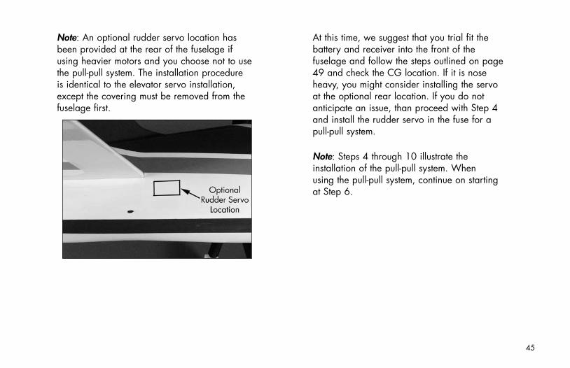
2. Attach the micro control horn to the elevator using a micro control horn backplate. Apply a few drops of medium CA to the backplate.
3. Install the micro control connector onto the elevator servo arm. Pass the elevator pushrod wire through the connector. With the radio on and elevator trim centered, center the elevator. Secure the elevator pushrod wire using the 2mm x 4mm screw and a small Phillips screwdriver.
Note: Make sure to set the elevator sub-trim to 0.
44
Note: An optional rudder servo location has been provided at the rear of the fuselage if using heavier motors and you choose not to use the pull-pull system. The installation procedure is identical to the elevator servo installation, except the covering must be removed from the fuselage first.
At this time, we suggest that you trial fit the battery and receiver into the front of the fuselage and follow the steps outlined on page 49 and check the CG location. If it is nose heavy, you might consider installing the servo at the optional rear location. If you do not anticipate an issue, than proceed with Step 4 and install the rudder servo in the fuse for a pull-pull system.
Note: Steps 4 through 10 illustrate the installation of the pull-pull system. When using the pull-pull system, continue on starting at Step 6.
45
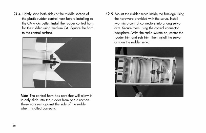
4. Lightly sand both sides of the middle section of the plastic rudder control horn before installing so the CA wicks better. Install the rudder control horn for the rudder using medium CA. Square the horn to the control surface.
Note: The control horn has ears that will allow it to only slide into the rudder from one direction. These ears rest against the side of the rudder when installed correctly.
5. Mount the rudder servo inside the fuselage using the hardware provided with the servo. Install two micro control connectors into a long servo arm. Secure them using the control connector backplates. With the radio system on, center the rudder trim and sub trim, then install the servo arm on the rudder servo.
46
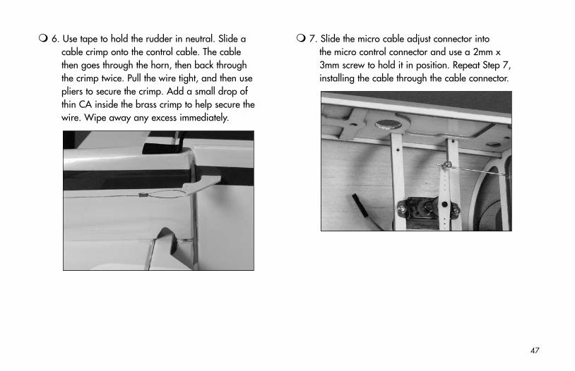
6. Use tape to hold the rudder in neutral. Slide a cable crimp onto the control cable. The cable then goes through the horn, then back through the crimp twice. Pull the wire tight, and then use pliers to secure the crimp. Add a small drop of thin CA inside the brass crimp to help secure the wire. Wipe away any excess immediately.
7. Slide the micro cable adjust connector into the micro control connector and use a 2mm x 3mm screw to hold it in position. Repeat Step 7, installing the cable through the cable connector.
47
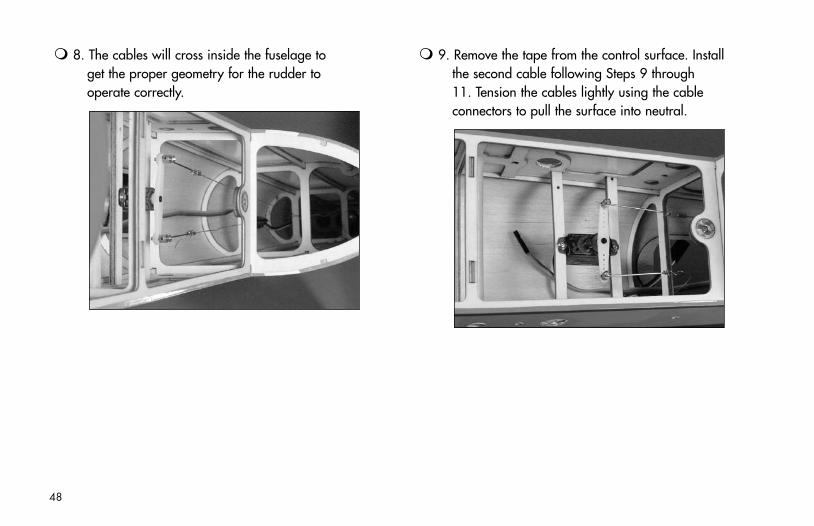
8. The cables will cross inside the fuselage to get the proper geometry for the rudder to operate correctly.
9. Remove the tape from the control surface. Install the second cable following Steps 9 through 11. Tension the cables lightly using the cable connectors to pull the surface into neutral.
48
Final AssemblyRequired Parts
• Fuselage• Receiver• 3-cell 11.1V Li-Po, 16GA• Hook and loop tape (2)• Canopy hatch
Required Tools and Adhesives• Thin CA
Optional Parts• Hook and loop strap
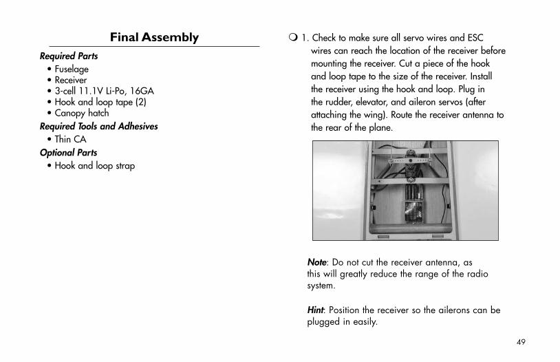
1. Check to make sure all servo wires and ESC wires can reach the location of the receiver before mounting the receiver. Cut a piece of the hook and loop tape to the size of the receiver. Install the receiver using the hook and loop. Plug in the rudder, elevator, and aileron servos (after attaching the wing). Route the receiver antenna to the rear of the plane.
Note: Do not cut the receiver antenna, as this will greatly reduce the range of the radio system.
Hint: Position the receiver so the ailerons can be plugged in easily.
49
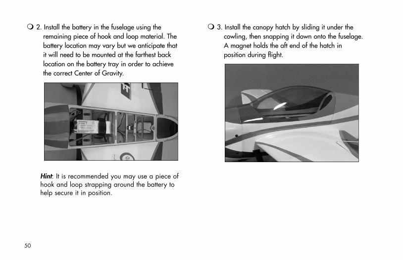
2. Install the battery in the fuselage using the remaining piece of hook and loop material. The battery location may vary but we anticipate that it will need to be mounted at the farthest back location on the battery tray in order to achieve the correct Center of Gravity.
Hint: It is recommended you may use a piece of hook and loop strapping around the battery to help secure it in position.
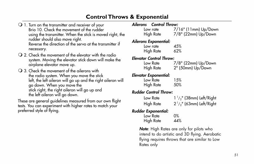
3. Install the canopy hatch by sliding it under the cowling, then snapping it down onto the fuselage. A magnet holds the aft end of the hatch in position during flight.
50
1. Turn on the transmitter and receiver of your Brio 10. Check the movement of the rudder using the transmitter. When the stick is moved right, the rudder should also move right. Reverse the direction of the servo at the transmitter if necessary.
2. Check the movement of the elevator with the radio system. Moving the elevator stick down will make the airplane elevator move up.
3. Check the movement of the ailerons with the radio system. When you move the stick left, the left aileron will go up and the right aileron will go down. When you move the stick right, the right aileron will go up and the left aileron will go down.
These are general guidelines measured from our own flight tests. You can experiment with higher rates to match your preferred style of flying.
Ailerons Control Throw: Low rate 7/16" (11mm) Up/Down High Rate 7/8" (22mm) Up/Down
Ailerons Exponential: Low rate 45% High Rate 62%
Elevator Control Throw: Low Rate 7/8" (22mm) Up/Down High Rate 2" (50mm) Up/Down
Elevator Exponential: Low Rate 15% High Rate 50%
Rudder Control Throw: Low Rate 1
1/2" (38mm) Left/Right High Rate 2
1/2" (63mm) Left/Right
Rudder Exponential: Low Rate 0% High Rate 44%
Note: High Rates are only for pilots who intend to do artistic and 3D flying. Aerobatic flying requires throws that are similar to Low Rates only
Control Throws & Exponential
51
An important part of preparing the aircraft for flight is properly balancing the model.
Caution: Do not inadvertently skip this step!
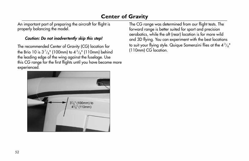
The recommended Center of Gravity (CG) location for the Brio 10 is 3
7/8" (100mm) to 4 3/8" (110mm) behind
the leading edge of the wing against the fuselage. Use this CG range for the first flights until you have become more experienced.
The CG range was determined from our flight tests. The forward range is better suited for sport and precision aerobatics, while the aft (rear) location is for more wild and 3D flying. You can experiment with the best locations to suit your flying style. Quique Somenzini flies at the 4
3/8" (110mm) CG location.
Center of Gravity
52

Notes:
53
GENERAL
1) I will not fly my model aircraft in sanctioned events, air shows or model flying demonstrations until it has been proven to be airworthy by having been previously, successfully flight tested.
2) I will not fly my model higher than approximately 400 feet within 3 miles of an airport without notifying the airport operator. I will give right-of-way and avoid flying in the proximity of full-scale aircraft. Where necessary, an observer shall be utilized to supervise flying to avoid having models fly in the proximity of full-scale aircraft.
3) Where established, I will abide by the safety rules for the flying site I use, and I will not willfully or deliberately fly my models in a careless, reckless and/or dangerous manner.
4) The maximum takeoff weight of a model is 55 pounds, except models flown under Experimental Aircraft rules.
5) I will not fly my model unless it is identified with my name and address or AMA number on or in the model. (This does not apply to models while being flown indoors.)
6) I will not operate models with metal-bladed propellers or with gaseous boosts, in which gases other than air enter their internal combustion engine(s); nor will I operate models with extremely hazardous fuels such as those containing tetranitromethane or hydrazine.
RADIO CONTROL
1) I will have completed a successful radio equipment ground range check before the first flight of a new or repaired model.
2) I will not fly my model aircraft in the presence of spectators until I become a qualified flier, unless assisted by an experienced helper.
54
2005 Official AMA National Model Aircraft Safety Code
3) At all flying sites a straight or curved line(s) must be established in front of which all flying takes place with the other side for spectators. Only personnel involved with flying the aircraft are allowed at or in front of the flight line. Intentional flying behind the flight line is prohibited.
4) I will operate my model using only radio control frequencies currently allowed by the Federal Communications Commission. (Only properly licensed Amateurs are authorized to operate equipment on Amateur Band frequencies.)
5) Flying sites separated by three miles or more are considered safe from site-to-site interference, even when both sites use the same frequencies. Any circumstances under three miles separation require a frequency management arrangement, which may be either an allocation of specific frequencies for each site or testing to determine that freedom from interference exists. Allocation plans or interference test reports shall be signed by the parties involved and provided to AMA Headquarters.
Documents of agreement and reports may exist between (1) two or more AMA Chartered Clubs, (2) AMA clubs and individual AMA members not associated with AMA Clubs, or (3) two or more individual AMA members.
6) For Combat, distance between combat engagement line and spectator line will be 500 feet per cubic inch of engine displacement. (Example: .40 engine = 200 feet.); electric motors will be based on equivalent combustion engine size. Additional safety requirements will be per the RC Combat section of the current Competition Regulations.
7) At air shows or model flying demonstrations, a single straight line must be established, one side of which is for flying, with the other side for spectators.
8) With the exception of events flown under AMA Competition rules, after launch, except for pilots or helpers being used, no powered model may be flown closer than 25 feet to any person.
9) Under no circumstances may a pilot or other person touch a powered model in flight.
55
2005 Official AMA National Model Aircraft Safety Code

8378.4
© 2006 Horizon Hobby, Inc. 4105 Fieldstone Road
Champaign, Illinois 61822 (877) 504-0233
www.horizonhobby.com www.E-fliteRC.com