Embed Size (px)
Citation preview
Brocade® NetIron® CER 2000 Series Ethernet Routers and Brocade NetIron® CES 2000 Series Ethernet Switches
Brocade Communications Systems, Inc. 1
Brocade® NetIron® CER 2000 Series Ethernet Routers and Brocade NetIron® CES 2000 Series Ethernet Switches
FIPS 140-2 Non-Proprietary Security Policy
Document Version 1.0
May 3, 2017
Brocade Communications Systems, Inc.
Copyright Brocade Communications 2017 May be reproduced only in its original entirety [without revision].
Brocade® NetIron® CER 2000 Series Ethernet Routers and Brocade NetIron® CES 2000 Series Ethernet Switches
Brocade Communications Systems, Inc. 2
Revision History
Revision History Revision Summary of changes
5/03/2017 1.0 Initial version
Brocade® NetIron® CER 2000 Series Ethernet Routers and Brocade NetIron® CES 2000 Series Ethernet Switches
Brocade Communications Systems, Inc. 3
© 2017 Brocade Communications Systems, Inc. All Rights Reserved.
This Brocade Communications Systems, Inc. Security Policy for Brocade® NetIron® CER 2000 series Ethernet Routers and Brocade CES 2000 series Routers embodies Brocade Communications Systems' confidential and proprietary intellectual property. Brocade Systems retains all title and ownership in the Specification, including any revisions.
This Specification is supplied AS IS and may be reproduced only in its original entirety [without revision]. Brocade Communications Systems makes no warranty, either express or implied, as to the use, operation, condition, or performance of the specification, and any unintended consequence it may on the user environment
Brocade® NetIron® CER 2000 Series Ethernet Routers and Brocade NetIron® CES 2000 Series Ethernet Switches
Brocade Communications Systems, Inc. 4
Table of contents:
Introduction ............................................................................................................................................................. 10
Overview ................................................................................................................................................................... 10
Brocade CER 2000 series /CES 2000 series .............................................................................................. 10
Tamper Evident Seal Application requirement ............................................................................................ 10
Additional overview information .................................................................................................................... 11
Power Supply support ................................................................................................................................. 11
Physical Layer interface for ports CER 2000 series / CES 2000 series ............................................. 11
Block Diagram .................................................................................................................................................. 12
Brocade CER 2000 series ....................................................................................................................................... 13
Brocade CES 2000 series ....................................................................................................................................... 17
Ports and Interfaces ................................................................................................................................................ 21
Brocade CER 2000 series/CES 2000 series ............................................................................................... 22
CER 2024C ................................................................................................................................................... 22
CER 2024F ................................................................................................................................................... 22
CES 2024C ................................................................................................................................................... 22
CES 2024F .................................................................................................................................................... 22
CER 2000 series / CES 2000 series Status LED ....................................................................................... 23
Modes of Operation .......................................................................................................................................... 24
Module Validation Level ................................................................................................................................... 24
Roles and Services .................................................................................................................................................. 25
Roles .................................................................................................................................................................. 25
The Crypto-officer role ................................................................................................................................ 25
Port Configuration Administrator role ....................................................................................................... 25
User role ....................................................................................................................................................... 25
NTP Peer role ............................................................................................................................................... 25
Services (Services in Approved mode) ............................................................................................................. 25
Services accessible by Crypto-officer role ................................................................................................... 27
6.2.1.1 Console ............................................................................................................................................... 27
6.2.1.2 NTP ...................................................................................................................................................... 27
6.2.1.3 SCP ...................................................................................................................................................... 27
6.2.1.4 SNMP ................................................................................................................................................... 27
6.2.1.5 SSHv2 .................................................................................................................................................. 28
6.2.1.6 Syslog .................................................................................................................................................. 29
6.2.1.7 TLS client ............................................................................................................................................ 29
Services accessible by Port Configuration Administrator role .................................................................. 29
6.2.2.1 Console ............................................................................................................................................... 29
6.2.2.2 NTP ...................................................................................................................................................... 29
6.2.2.3 SNMP ................................................................................................................................................... 30
Brocade® NetIron® CER 2000 Series Ethernet Routers and Brocade NetIron® CES 2000 Series Ethernet Switches
Brocade Communications Systems, Inc. 5
6.2.2.4 SSHv2 .................................................................................................................................................. 30
6.2.2.5 Syslog .................................................................................................................................................. 30
6.2.2.6 TLS client ............................................................................................................................................ 30
Services accessible by User role ................................................................................................................. 30
6.2.3.1 Console ............................................................................................................................................... 30
6.2.3.2 NTP ...................................................................................................................................................... 30
6.2.3.3 SNMP ................................................................................................................................................... 30
6.2.3.4 SSHv2 .................................................................................................................................................. 31
6.2.3.5 Syslog .................................................................................................................................................. 31
6.2.3.6 TLS client ............................................................................................................................................ 31
Services accessible by NTP Peer role .......................................................................................................... 31
6.2.4.1 NTP ....................................................................................................................................................... 31
Non-Approved Mode Services .......................................................................................................................... 32
Non-Approved Algorithms ............................................................................................................................ 36
Algorithm certificates .............................................................................................................................................. 38
Algorithm certificates in CER 2000 series / CES 2000 series ....................................................................... 38
Non-Approved but allowed cryptographic methods .................................................................................... 39
Policies ..................................................................................................................................................................... 40
Security Rules ................................................................................................................................................... 40
Cryptographic Module Operational Rules ................................................................................................. 42
Authentication ................................................................................................................................................... 43
Line Authentication Method ....................................................................................................................... 44
Enable Authentication Method .................................................................................................................. 44
Local Authentication Method ..................................................................................................................... 44
RADIUS Authentication Method ................................................................................................................. 44
TACACS+ Authentication Method ............................................................................................................... 44
Strength of Authentication ......................................................................................................................... 45
Access Control and Critical Security Parameters (CSPs) ................................................................................ 46
Access Control and Critical Security Parameters (CSPs) for the Crypto-officer role ................................. 46
Access Control and Critical Security Parameters (CSPs) for Port Configuration Administrator role ........ 48
Access Control and Critical Security Parameters (CSPs) for User role ...................................................... 49
Access Control and Critical Security Parameters (CSPs) for NTP Peer role .............................................. 50
CSP Zeroization ........................................................................................................................................... 50
Physical Security ............................................................................................................................................... 51
Crypto-officer Guidance ........................................................................................................................................... 53
FIPS Approved Mode Status ............................................................................................................................. 53
FIPS Approved Mode ....................................................................................................................................... 55
Invoking FIPS Approved Mode ..................................................................................................................... 55
9.2.1.1 Invoking FIPS Approved Mode for Brocade CER 2000 series and CES 2000 series Devices. 55
Brocade® NetIron® CER 2000 Series Ethernet Routers and Brocade NetIron® CES 2000 Series Ethernet Switches
Brocade Communications Systems, Inc. 6
Negating FIPS Approved Mode .................................................................................................................... 56
9.2.2.1 Negating FIPS Approved Mode for Brocade CER 2000 Series and CES 2000 Series Devices 56
Mitigation of other attacks ...................................................................................................................................... 56
Glossary ................................................................................................................................................................... 57
Appendix A: Tamper Evident Seal Application Procedure ..................................................................................... 58
Brocade CER 2000 series ................................................................................................................................ 58
CER 2024C-4X-RT devices ........................................................................................................................... 58
CER 2024F-4X-RT devices ........................................................................................................................... 61
Brocade CES 2000 series devices ................................................................................................................... 64
CES 2024C-4X devices ................................................................................................................................ 64
CES 2024F-4X devices ................................................................................................................................. 66
Appendix B: Critical Security Parameters ............................................................................................................... 68
Authentication Key ............................................................................................................................................ 68
KDF .................................................................................................................................................................... 69
Management card (MP) DRBG ......................................................................................................................... 70
Private Keys ....................................................................................................................................................... 72
Public Keys ........................................................................................................................................................ 73
Session Keys ..................................................................................................................................................... 76
Shared Secret ................................................................................................................................................... 77
Appendix C: CKG as per SP800-133 ...................................................................................................................... 80
Appendix D: Components Excluded from FIPS 140-2 Requirements ................................................................... 80
Brocade® NetIron® CER 2000 Series Ethernet Routers and Brocade NetIron® CES 2000 Series Ethernet Switches
Brocade Communications Systems, Inc. 7
Table of tables:
Table 1 Overview – Power Supply support for CER 2000 series and CES 2000 series products .................................. 11
Table 2 Overview – Port Physical Layer interface for CER 2000 series and CES 2000 series products ....................... 11
Table 3 CER 2000 series Firmware Version ...................................................................................................................... 13
Table 4 CER 2000 series Part Numbers ............................................................................................................................ 13
Table 5 CER 2000 series Power Supply Module Part Numbers ....................................................................................... 14
Table 6 CER 2000 Software License ................................................................................................................................. 14
Table 7 Validated CER 2000 series Configuration ............................................................................................................ 14
Table 8 - CES 2000 series Firmware Version .................................................................................................................... 17
Table 9 - CES 2000 series Part Numbers .......................................................................................................................... 17
Table 10 - CES 2000 series Power Supply Module Part Numbers ................................................................................... 18
Table 11 - Validated CES 2000 series Configuration ........................................................................................................ 18
Table 12 Physical/Logical Interface Correspondence ...................................................................................................... 21
Table 13 Power and fan status LEDs for the CER 2000 series and CES 2000 series models ...................................... 23
Table 14 NetIron Security Levels ....................................................................................................................................... 24
Table 15 – List of services in Approved mode of operation ............................................................................................. 25
Table 16 FIPS Approved Cryptographic Functions ............................................................................................................ 26
Table 17 Non-Approved Cryptographic Functions Allowed in FIPS Approved Mode ........................................................ 26
Table 18 Functions/Services, Roles in Non-Approved Mode Services ............................................................................ 35
Table 19 Non-Approved Algorithms .................................................................................................................................... 36
Table 20 Algorithm Certificates for CER 2000 series / CES 2000 series ........................................................................ 38
Table 21 Power-Up Self-Tests - Cryptographic Known Answer Tests (KAT) ...................................................................... 40
Table 22 Conditional Self-Tests .......................................................................................................................................... 41
Table 23 - Summary of authentication methods available for each role ......................................................................... 43
Table 24 - Access Control and CSPs for the Crypto-officer role ........................................................................................ 47
Table 25 - Access Control and CSPs for the Port Configuration role ................................................................................ 49
Table 26 - Access Control and CSPs for the User role ...................................................................................................... 50
Table 27 - Access Control and CSPs for the NTP Peer role ............................................................................................... 50
Table 28 Inspection of Physical Security Mechanisms ..................................................................................................... 51
Table 29 Sample output – CES/CER in non-Approved mode ........................................................................................... 53
Table 30 Sample output – CES/CER in FIPS Approved mode .......................................................................................... 54
Table 31 Mitigation of other attacks .................................................................................................................................. 56
Table 32 Glossary ................................................................................................................................................................ 57
Table 33 – SKU Excluded from FIPS 140-2 requirement – CES 2000 series and CER 200 series DC Power Supply Module ................................................................................................................................................................................. 80
Brocade® NetIron® CER 2000 Series Ethernet Routers and Brocade NetIron® CES 2000 Series Ethernet Switches
Brocade Communications Systems, Inc. 8
Table of figures:
Figure 1 - Block Diagram ..................................................................................................................................................... 12
Figure 2 - BR-CER-2024F-4X-RT-DC with Base: BR-CER-2024F-4X-RT-DC and License: SW-CER-2024-RTUPG ........... 15
Figure 3 - BR-CER-2024F-4X-RT-DC backside with Power supply RPS9DC (DC Power Supply) ...................................... 15
Figure 4 - BR-CER-2024C-4X-RT-DC with Base: BR-CER-2024C-4X-RT-DC and License: SW-CER-2024-RTUPG ........... 15
Figure 5 - BR-CER-2024C-4X-RT-DC backside with Power supply RPS9DC (DC Power Supply) ...................................... 15
Figure 6 - BR-CER-2024F-4X-RT-AC with Base: BR-CER-2024F-4X-RT-AC and License: SW-CER-2024-RTUPG ............ 15
Figure 7 - BR-CER-2024F-4X-RT-AC backside with Power supply RPS9 (AC Power Supply) ............................................ 16
Figure 8 - BR-CER-2024C-4X-RT-AC with Base: BR-CER-2024C-4X-RT-AC and License: SW-CER-2024-RTUPG ............ 16
Figure 9 - BR-CER-2024C-4X-RT-AC backside with Power supply RPS9 (AC Power Supply) ........................................... 16
Figure 10 - Front view of BR-CES-2024C-4X-AC ................................................................................................................ 19
Figure 11 - BR-CES-2024C-4X-AC backside with Power supply: RPS9 (AC Power supply) .............................................. 19
Figure 12 - Front view of BR-CES-2024C-4X-DC ................................................................................................................ 19
Figure 13 - BR-CES-2024C-4X-DC backside with Power supply: RPS9DC (DC Power supply) ........................................ 19
Figure 14 - Front view of BR-CES-2024F-4X-AC ................................................................................................................. 19
Figure 15 - BR-CES-2024F-4X-AC backside with Power supply: RPS9 (AC Power supply) .............................................. 20
Figure 16 - Front view of BR-CES-2024F-4X-DC ................................................................................................................ 20
Figure 17 - BR-CES-2024F-4X-DC backside with Power supply: RPS9DC (DC Power supply) ........................................ 20
Figure 18 - Top front view of Brocade CER 2024C-4X-RT device with security seals ...................................................... 59
Figure 19 - Right view of Brocade CER 2024C-4X-RT device with security seals ............................................................ 59
Figure 20 - Left side view of Brocade CER 2024C-4X-RT device with security seals ...................................................... 60
Figure 21 - Rear view of Brocade CER 2024C-4X-RT device with security seals ............................................................. 60
Figure 22 - Bottom view of Brocade CER 2024C-4X-RT device with security seals ........................................................ 61
Figure 23 - Top front view of Brocade CER 2024F-4X-RT device with security seals ...................................................... 62
Figure 24 - Right side view of Brocade CER 2024F-4X-RT device with security seals .................................................... 62
Figure 25 - Left side view of Brocade CER 2024F-4X-RT device with security seals....................................................... 62
Figure 26 - Rear view of Brocade CER 2024F-4X-RT device with security seals ............................................................. 63
Figure 27 - Bottom view of Brocade CER 2024F-4X-RT device with security seals ........................................................ 63
Figure 28 - Top front view of Brocade CES 2024C-4X device with security seals ........................................................... 64
Figure 29 - Right side view of Brocade CES 2024C-4X device with security seals .......................................................... 64
Figure 30 - Left side view of Brocade CES 2024C-4X device with security seals ............................................................ 65
Figure 31 - Rear view of Brocade CES 2024C-4X device with security seals .................................................................. 65
Figure 32 - Bottom view of Brocade CES 2024C-4X device with security seals .............................................................. 65
Figure 33 - Top front view of Brocade CES 2024F-4X device with security seals ........................................................... 66
Figure 34 - Right side view of Brocade CES 2024F-4X device with security seals .......................................................... 66
Figure 35 - Left side view of Brocade CES 2024F-4X device with security seals ............................................................ 67
Figure 36 - Rear side view of Brocade CES 2024F-4X device with security seals ........................................................... 67
Figure 37 - Bottom view of Brocade CES 2024F-4X device with security seals .............................................................. 67
Brocade® NetIron® CER 2000 Series Ethernet Routers and Brocade NetIron® CES 2000 Series Ethernet Switches
Brocade Communications Systems, Inc. 9

Brocade® NetIron® CER 2000 Series Ethernet Routers and Brocade NetIron® CES 2000 Series Ethernet Switches
Brocade Communications Systems, Inc. 10
Introduction
The Brocade NetIron CER 2000 series is a family of compact 1U routers that are purpose-built for high- performance Ethernet edge routing, as well as providing connectivity between sites using MPLS/VPLS. These fixed-form routers can store a complete Internet table and support advanced MPLS features such as Traffic Engineering and VPLS. They are ideal for supporting a wide range of applications in Metro Ethernet, data center and campus networks. The NetIron CER 2000 series is available in 24-port 1 Gigabit Ethernet (GbE) copper and hybrid fiber configurations with two optional 10 GbE uplink ports. To help ensure high performance, all the ports are capable of forwarding IP and MPLS packets at wire speed without oversubscription. With less than 5 watts/Gbps of power consumption, service providers can push up to 136 Gbps of triple-play services through the NetIron CER 2000 series while reducing their carbon footprint.
The Brocade NetIron CES 2000 series is a family of compact 1U, multiservice edge/aggregation switches that combine powerful capabilities with high performance and availability. The switches provide a broad set of advanced Layer 2, IPv4, IPv6, and MPLS capabilities in the same device. As a result, they support a diverse set of applications in metro edge, service provider, mobile backhaul wholesale, data center, and large enterprise networks.
Overview
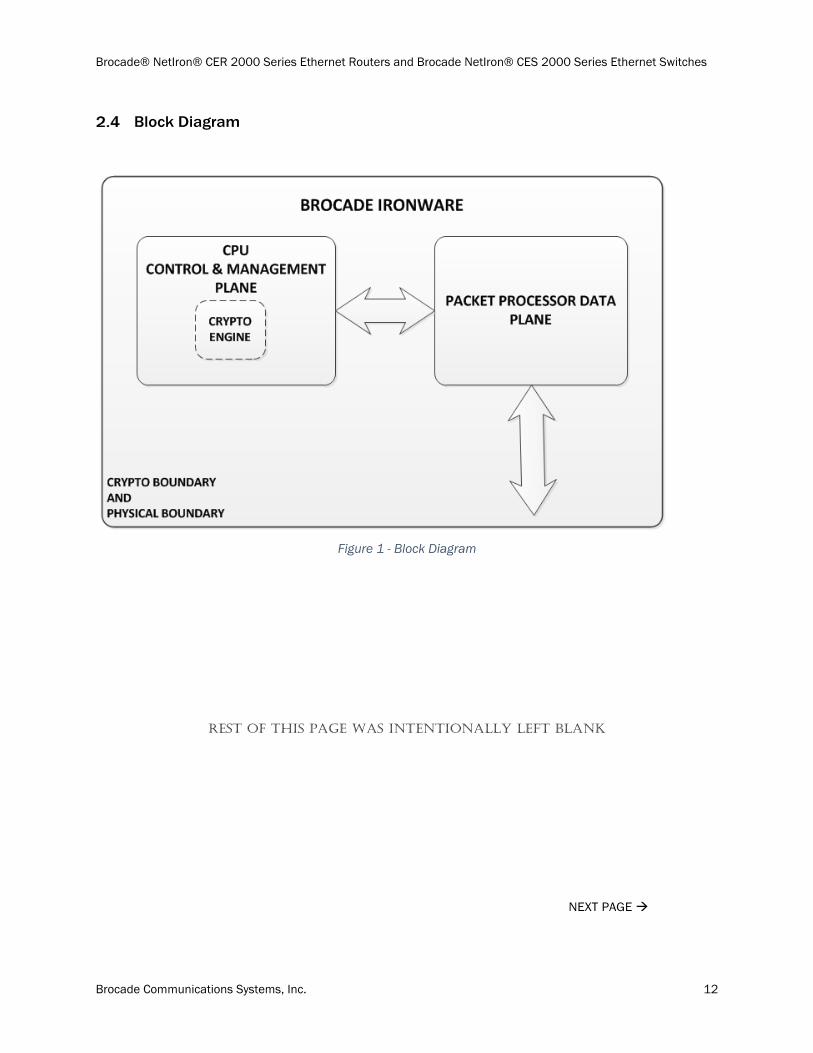
Brocade routers provide high-performance routing to service providers, metro topologies, and Internet Exchange Points. Each router is a multi-chip standalone cryptographic module. Each device has an opaque enclosure with tamper detection tape for detecting any unauthorized physical access to the device. The Brocade NetIron family of products include both chassis and fixed-port devices.
Brocade CER 2000 series /CES 2000 series
The cryptographic boundary of a Brocade CER 2000 series / CES 2000 series device includes the following components:
The outer perimeter of the metal chassis, including the removable cover and pre-installed fan assembly.
The power supplies
NOTE: The CER 2000 series and CES 2000 series are fixed-port devices
Tamper Evident Seal Application requirement
For a CER 2000 series and CES 2000 series to operate as a validated cryptographic module, the tamper evident seals supplied in Brocade XBR-000195 must be installed as defined in section, 12 - Appendix A: Tamper Evident Seal Application Procedure
The security officer is responsible for storing and controlling the inventory of any unused seals. The unused seals shall be stored in plastic bags in a cool, dry environment between 60° and 70° F (15° to 20° C) and less than 50% relative humidity. Rolls should be stored flat on a slit edge or suspended by the core.
The security officer shall maintain a serial number inventory of all used and unused tamper evident seals. The security officer shall periodically monitor the state of all applied seals for evidence of tampering. A seal serial number mismatch, a seal placement change, a checkerboard destruct pattern that appears in peeled film and adhesive residue on the substrate are evidence of tampering. The security officer shall periodically view each applied seal under a UV light to verify the presence of a UV wallpaper pattern. The lack of a wallpaper pattern is evidence of tampering. The security officer is responsible for returning a module to a validated cryptographic state after any intentional or unintentional reconfiguration of the physical security measures.
NEXT PAGE
Brocade® NetIron® CER 2000 Series Ethernet Routers and Brocade NetIron® CES 2000 Series Ethernet Switches
Brocade Communications Systems, Inc. 11
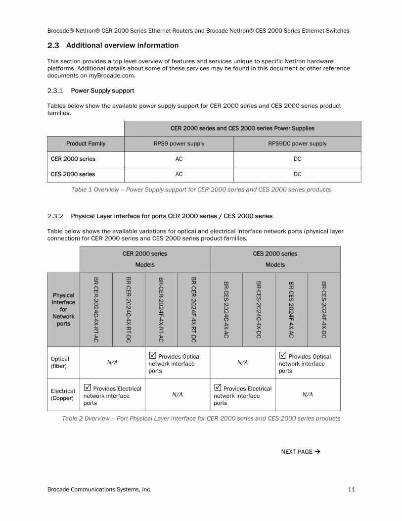
Additional overview information
This section provides a top level overview of features and services unique to specific NetIron hardware platforms. Additional details about some of these services may be found in this document or other reference documents on myBrocade.com.
Power Supply support
Tables below show the available power supply support for CER 2000 series and CES 2000 series product families.
CER 2000 series and CES 2000 series Power Supplies
Product Family RPS9 power supply RPS9DC power supply
CER 2000 series AC DC
CES 2000 series AC DC
Table 1 Overview – Power Supply support for CER 2000 series and CES 2000 series products
Physical Layer interface for ports CER 2000 series / CES 2000 series
Table below shows the available variations for optical and electrical interface network ports (physical layer connection) for CER 2000 series and CES 2000 series product families.
CER 2000 series
Models
CES 2000 series
Models
Physical interface
for Network
ports
BR
-CER-2
02
4C-4
X-RT-AC
BR
-CER-2
02
4C-4
X-RT-D
C
BR
-CER-2
02
4F-4
X-RT-AC
BR
-CER-2
02
4F-4
X-RT-D
C
BR
-CES-20
24
C-4
X-AC
BR
-CES-20
24
C-4
X-DC
BR
-CES-20
24
F-4X-AC
BR
-CES-20
24
F-4X-D
C
Optical (fiber) N/A
Provides Optical network interface ports
N/A Provides Optical network interface ports
Electrical (Copper)
Provides Electrical network interface ports
N/A Provides Electrical network interface ports
N/A
Table 2 Overview – Port Physical Layer interface for CER 2000 series and CES 2000 series products
NEXT PAGE
Brocade® NetIron® CER 2000 Series Ethernet Routers and Brocade NetIron® CES 2000 Series Ethernet Switches
Brocade Communications Systems, Inc. 12
Block Diagram
Figure 1 - Block Diagram
REST OF THIS PAGE WAS INTENTIONALLY LEFT BLANK
NEXT PAGE
Brocade® NetIron® CER 2000 Series Ethernet Routers and Brocade NetIron® CES 2000 Series Ethernet Switches
Brocade Communications Systems, Inc. 13
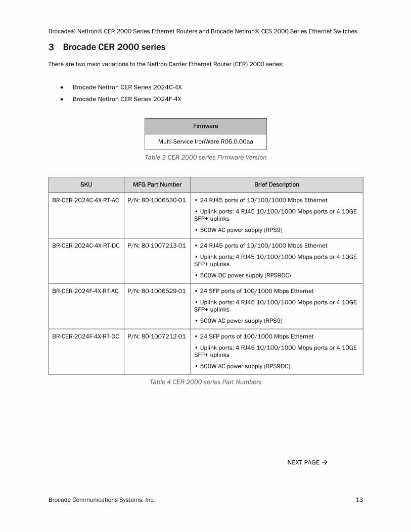
Brocade CER 2000 series
There are two main variations to the NetIron Carrier Ethernet Router (CER) 2000 series:
Brocade NetIron CER Series 2024C-4X
Brocade NetIron CER Series 2024F-4X
Firmware
Multi-Service IronWare R06.0.00aa
Table 3 CER 2000 series Firmware Version
SKU MFG Part Number Brief Description
BR-CER-2024C-4X-RT-AC P/N: 80-1006530-01 • 24 RJ45 ports of 10/100/1000 Mbps Ethernet
• Uplink ports: 4 RJ45 10/100/1000 Mbps ports or 4 10GE SFP+ uplinks
• 500W AC power supply (RPS9)
BR-CER-2024C-4X-RT-DC P/N: 80-1007213-01 • 24 RJ45 ports of 10/100/1000 Mbps Ethernet
• Uplink ports: 4 RJ45 10/100/1000 Mbps ports or 4 10GE SFP+ uplinks
• 500W DC power supply (RPS9DC)
BR-CER-2024F-4X-RT-AC P/N: 80-1006529-01 • 24 SFP ports of 100/1000 Mbps Ethernet
• Uplink ports: 4 RJ45 10/100/1000 Mbps ports or 4 10GE SFP+ uplinks
• 500W AC power supply (RPS9)
BR-CER-2024F-4X-RT-DC P/N: 80-1007212-01 • 24 SFP ports of 100/1000 Mbps Ethernet
• Uplink ports: 4 RJ45 10/100/1000 Mbps ports or 4 10GE SFP+ uplinks
• 500W AC power supply (RPS9DC)
Table 4 CER 2000 series Part Numbers
NEXT PAGE
Brocade® NetIron® CER 2000 Series Ethernet Routers and Brocade NetIron® CES 2000 Series Ethernet Switches
Brocade Communications Systems, Inc. 14
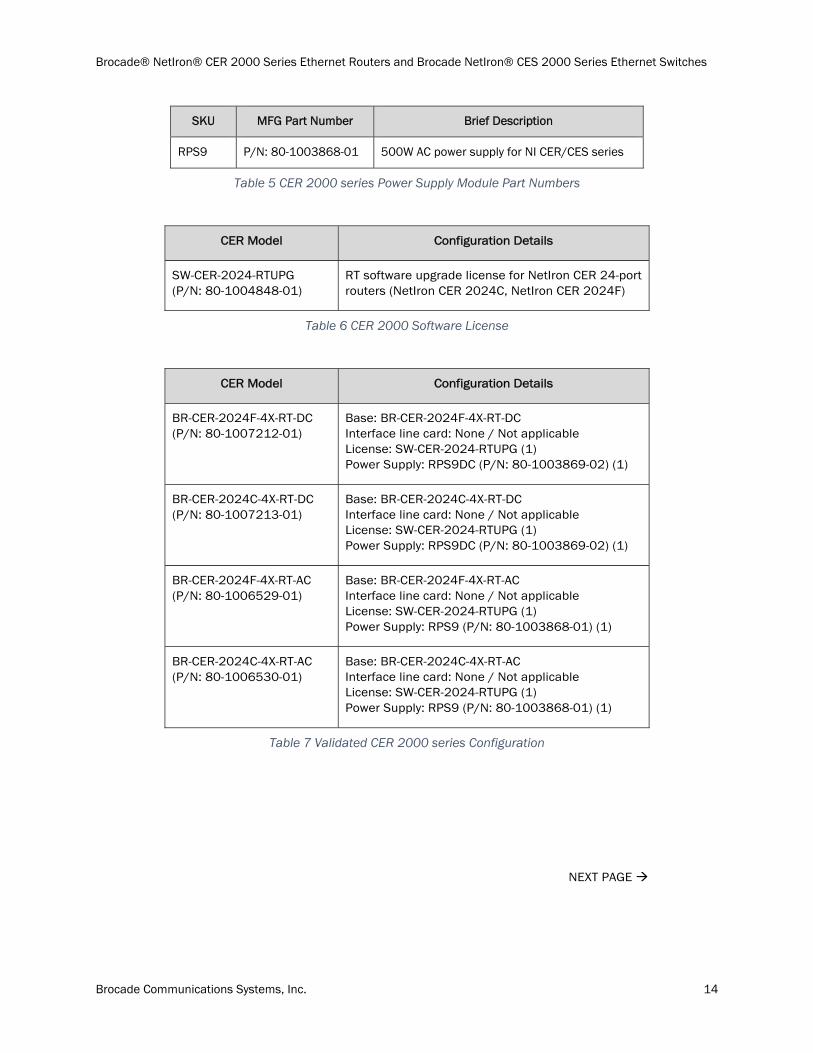
SKU MFG Part Number Brief Description
RPS9 P/N: 80-1003868-01 500W AC power supply for NI CER/CES series
Table 5 CER 2000 series Power Supply Module Part Numbers
CER Model Configuration Details
SW-CER-2024-RTUPG (P/N: 80-1004848-01)
RT software upgrade license for NetIron CER 24-port routers (NetIron CER 2024C, NetIron CER 2024F)
Table 6 CER 2000 Software License
CER Model Configuration Details
BR-CER-2024F-4X-RT-DC (P/N: 80-1007212-01)
Base: BR-CER-2024F-4X-RT-DC Interface line card: None / Not applicable License: SW-CER-2024-RTUPG (1) Power Supply: RPS9DC (P/N: 80-1003869-02) (1)
BR-CER-2024C-4X-RT-DC (P/N: 80-1007213-01)
Base: BR-CER-2024C-4X-RT-DC Interface line card: None / Not applicable License: SW-CER-2024-RTUPG (1) Power Supply: RPS9DC (P/N: 80-1003869-02) (1)
BR-CER-2024F-4X-RT-AC (P/N: 80-1006529-01)
Base: BR-CER-2024F-4X-RT-AC Interface line card: None / Not applicable License: SW-CER-2024-RTUPG (1) Power Supply: RPS9 (P/N: 80-1003868-01) (1)
BR-CER-2024C-4X-RT-AC (P/N: 80-1006530-01)
Base: BR-CER-2024C-4X-RT-AC Interface line card: None / Not applicable License: SW-CER-2024-RTUPG (1) Power Supply: RPS9 (P/N: 80-1003868-01) (1)
Table 7 Validated CER 2000 series Configuration
NEXT PAGE
Brocade® NetIron® CER 2000 Series Ethernet Routers and Brocade NetIron® CES 2000 Series Ethernet Switches
Brocade Communications Systems, Inc. 15
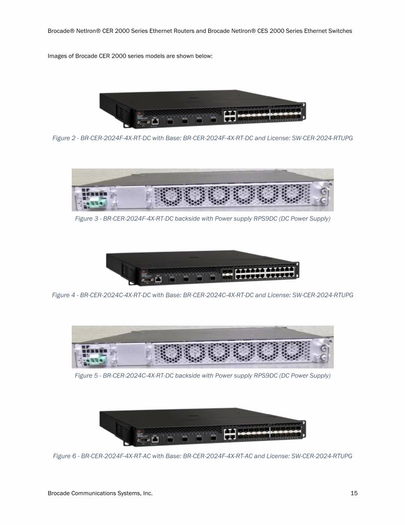
Images of Brocade CER 2000 series models are shown below:
Figure 2 - BR-CER-2024F-4X-RT-DC with Base: BR-CER-2024F-4X-RT-DC and License: SW-CER-2024-RTUPG
Figure 3 - BR-CER-2024F-4X-RT-DC backside with Power supply RPS9DC (DC Power Supply)
Figure 4 - BR-CER-2024C-4X-RT-DC with Base: BR-CER-2024C-4X-RT-DC and License: SW-CER-2024-RTUPG
Figure 5 - BR-CER-2024C-4X-RT-DC backside with Power supply RPS9DC (DC Power Supply)
Figure 6 - BR-CER-2024F-4X-RT-AC with Base: BR-CER-2024F-4X-RT-AC and License: SW-CER-2024-RTUPG
Brocade® NetIron® CER 2000 Series Ethernet Routers and Brocade NetIron® CES 2000 Series Ethernet Switches
Brocade Communications Systems, Inc. 16
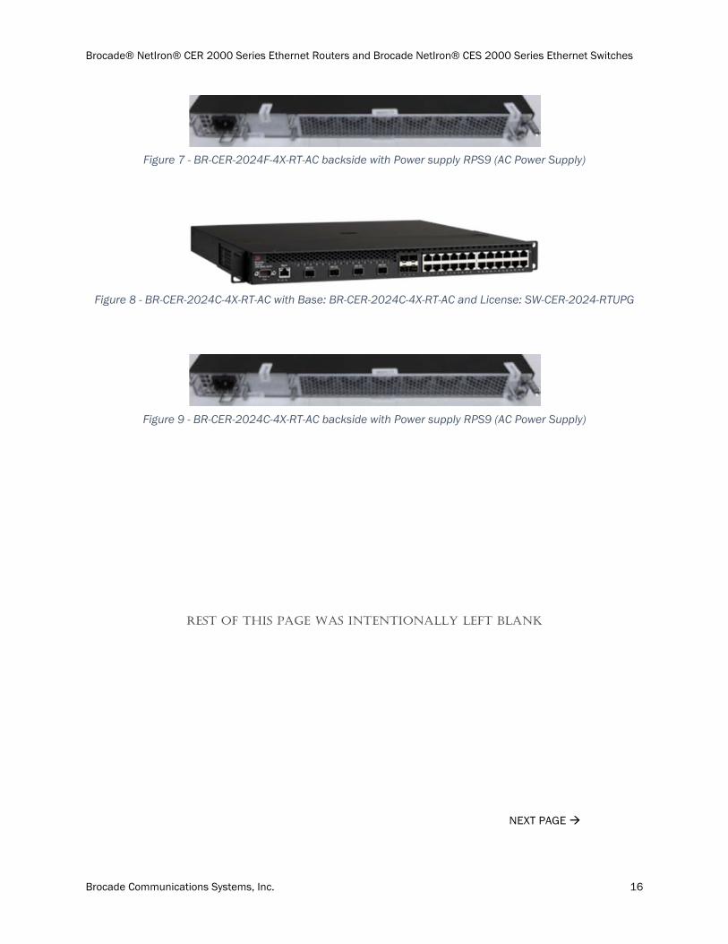
Figure 7 - BR-CER-2024F-4X-RT-AC backside with Power supply RPS9 (AC Power Supply)
Figure 8 - BR-CER-2024C-4X-RT-AC with Base: BR-CER-2024C-4X-RT-AC and License: SW-CER-2024-RTUPG
Figure 9 - BR-CER-2024C-4X-RT-AC backside with Power supply RPS9 (AC Power Supply)
REST OF THIS PAGE WAS INTENTIONALLY LEFT BLANK
NEXT PAGE
Brocade® NetIron® CER 2000 Series Ethernet Routers and Brocade NetIron® CES 2000 Series Ethernet Switches
Brocade Communications Systems, Inc. 17
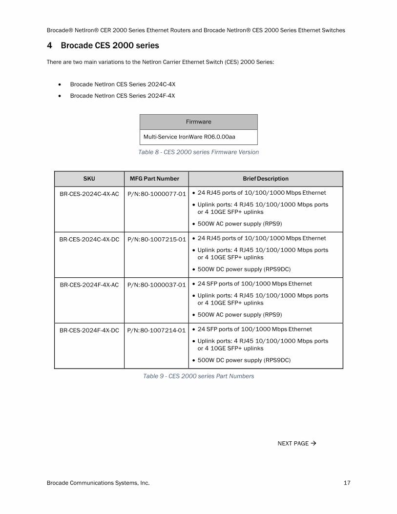
Brocade CES 2000 series
There are two main variations to the NetIron Carrier Ethernet Switch (CES) 2000 Series:
Brocade NetIron CES Series 2024C-4X
Brocade NetIron CES Series 2024F-4X
Firmware
Multi-Service IronWare R06.0.00aa
Table 8 - CES 2000 series Firmware Version
SKU MFG Part Number Brief Description
BR-CES-2024C-4X-AC P/N: 80-1000077-01 24 RJ45 ports of 10/100/1000 Mbps Ethernet
Uplink ports: 4 RJ45 10/100/1000 Mbps ports or 4 10GE SFP+ uplinks
500W AC power supply (RPS9)
BR-CES-2024C-4X-DC P/N: 80-1007215-01 24 RJ45 ports of 10/100/1000 Mbps Ethernet
Uplink ports: 4 RJ45 10/100/1000 Mbps ports or 4 10GE SFP+ uplinks
500W DC power supply (RPS9DC)
BR-CES-2024F-4X-AC P/N: 80-1000037-01 24 SFP ports of 100/1000 Mbps Ethernet
Uplink ports: 4 RJ45 10/100/1000 Mbps ports or 4 10GE SFP+ uplinks
500W AC power supply (RPS9)
BR-CES-2024F-4X-DC P/N: 80-1007214-01 24 SFP ports of 100/1000 Mbps Ethernet
Uplink ports: 4 RJ45 10/100/1000 Mbps ports or 4 10GE SFP+ uplinks
500W DC power supply (RPS9DC)
Table 9 - CES 2000 series Part Numbers
NEXT PAGE
Brocade® NetIron® CER 2000 Series Ethernet Routers and Brocade NetIron® CES 2000 Series Ethernet Switches
Brocade Communications Systems, Inc. 18
SKU MFG Part Number Brief Description
RPS9 P/N: 80-1003868-01 500W AC power supply for NetIron CER/CES series
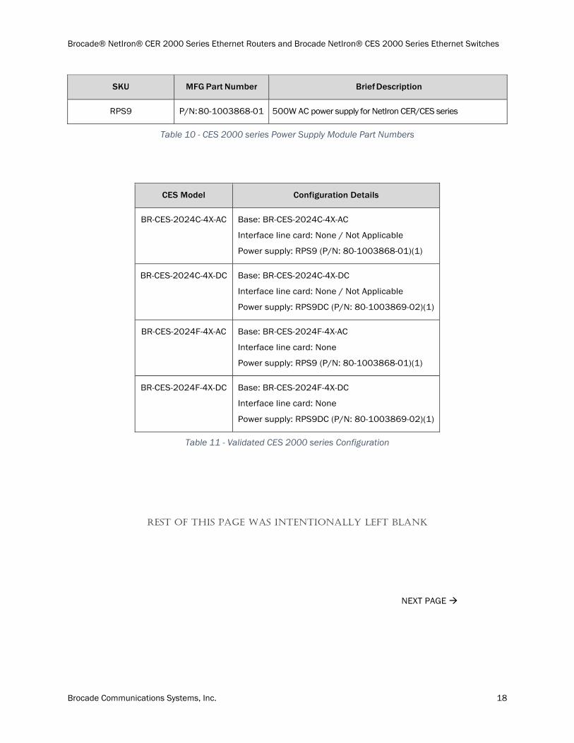
Table 10 - CES 2000 series Power Supply Module Part Numbers
CES Model Configuration Details
BR-CES-2024C-4X-AC Base: BR-CES-2024C-4X-AC
Interface line card: None / Not Applicable
Power supply: RPS9 (P/N: 80-1003868-01)(1)
BR-CES-2024C-4X-DC Base: BR-CES-2024C-4X-DC
Interface line card: None / Not Applicable
Power supply: RPS9DC (P/N: 80-1003869-02)(1)
BR-CES-2024F-4X-AC Base: BR-CES-2024F-4X-AC
Interface line card: None
Power supply: RPS9 (P/N: 80-1003868-01)(1)
BR-CES-2024F-4X-DC Base: BR-CES-2024F-4X-DC
Interface line card: None
Power supply: RPS9DC (P/N: 80-1003869-02)(1)
Table 11 - Validated CES 2000 series Configuration
REST OF THIS PAGE WAS INTENTIONALLY LEFT BLANK
NEXT PAGE
Brocade® NetIron® CER 2000 Series Ethernet Routers and Brocade NetIron® CES 2000 Series Ethernet Switches
Brocade Communications Systems, Inc. 19
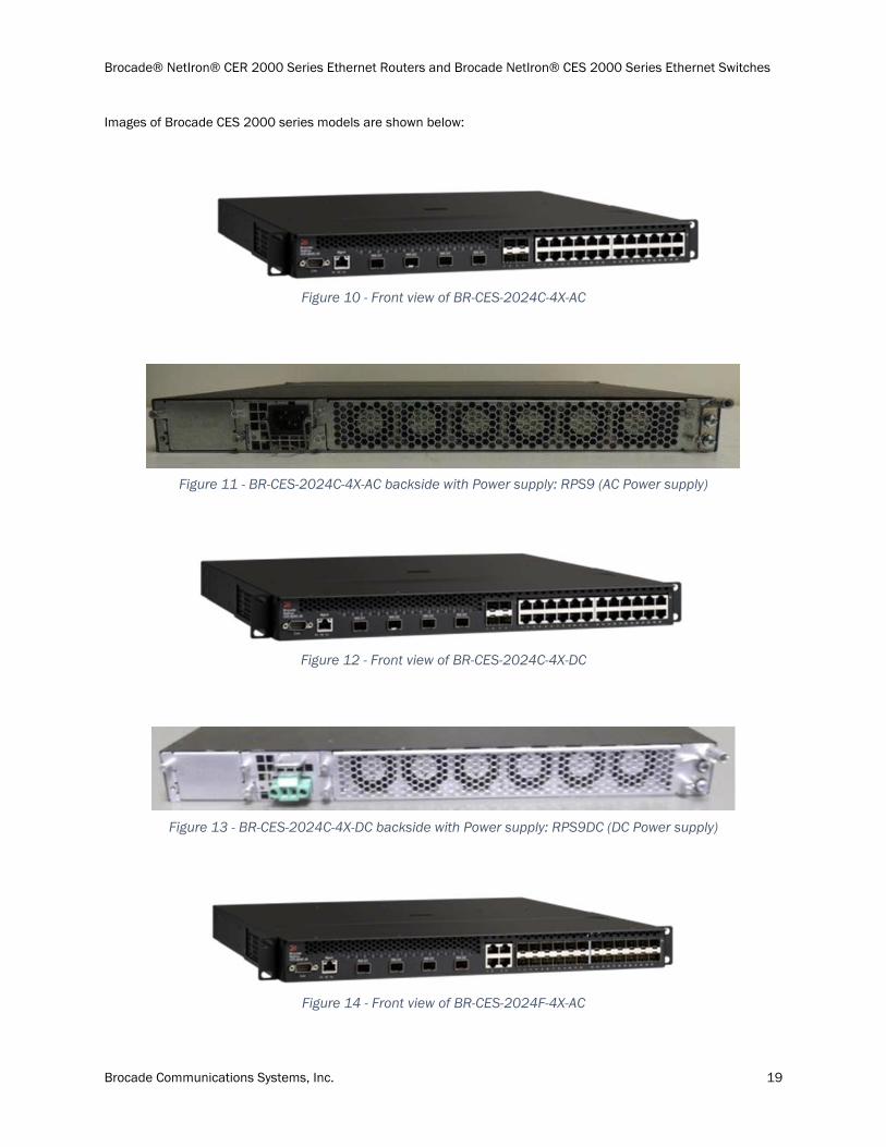
Images of Brocade CES 2000 series models are shown below:
Figure 10 - Front view of BR-CES-2024C-4X-AC
Figure 11 - BR-CES-2024C-4X-AC backside with Power supply: RPS9 (AC Power supply)
Figure 12 - Front view of BR-CES-2024C-4X-DC
Figure 13 - BR-CES-2024C-4X-DC backside with Power supply: RPS9DC (DC Power supply)
Figure 14 - Front view of BR-CES-2024F-4X-AC
Brocade® NetIron® CER 2000 Series Ethernet Routers and Brocade NetIron® CES 2000 Series Ethernet Switches
Brocade Communications Systems, Inc. 20
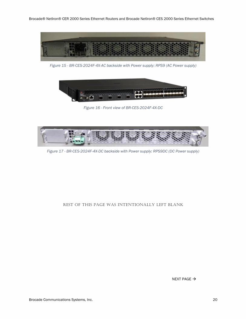
Figure 15 - BR-CES-2024F-4X-AC backside with Power supply: RPS9 (AC Power supply)
Figure 16 - Front view of BR-CES-2024F-4X-DC
Figure 17 - BR-CES-2024F-4X-DC backside with Power supply: RPS9DC (DC Power supply)
REST OF THIS PAGE WAS INTENTIONALLY LEFT BLANK
NEXT PAGE
Brocade® NetIron® CER 2000 Series Ethernet Routers and Brocade NetIron® CES 2000 Series Ethernet Switches
Brocade Communications Systems, Inc. 21
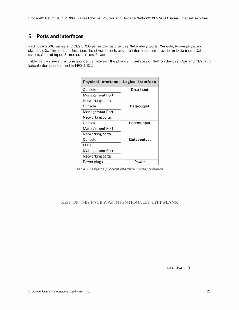
Ports and Interfaces
Each CER 2000 series and CES 2000 series device provides Networking ports, Console, Power plugs and status LEDs. This section describes the physical ports and the interfaces they provide for Data input, Data output, Control input, Status output and Power.
Table below shows the correspondence between the physical interfaces of NetIron devices (CER and CES) and logical interfaces defined in FIPS 140-2.
Physical Interface Logical Interface
Console Data input
Management Port
Networking ports
Console Data output
Management Port
Networking ports
Console Control input
Management Port
Networking ports
Console Status output
LEDs
Management Port
Networking ports
Power plugs Power
Table 12 Physical/Logical Interface Correspondence
REST OF THIS PAGE WAS INTENTIONALLY LEFT BLANK
NEXT PAGE
Brocade® NetIron® CER 2000 Series Ethernet Routers and Brocade NetIron® CES 2000 Series Ethernet Switches
Brocade Communications Systems, Inc. 22
Brocade CER 2000 series/CES 2000 series
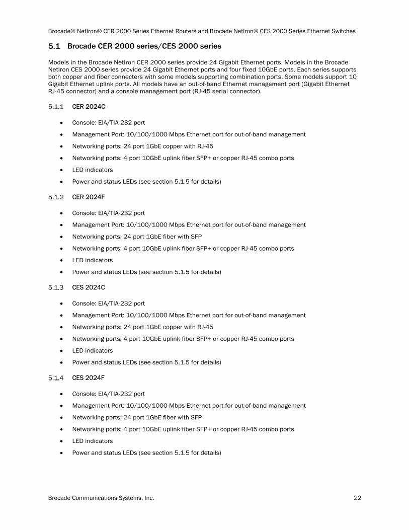
Models in the Brocade NetIron CER 2000 series provide 24 Gigabit Ethernet ports. Models in the Brocade NetIron CES 2000 series provide 24 Gigabit Ethernet ports and four fixed 10GbE ports. Each series supports both copper and fiber connecters with some models supporting combination ports. Some models support 10 Gigabit Ethernet uplink ports. All models have an out-of-band Ethernet management port (Gigabit Ethernet RJ-45 connector) and a console management port (RJ-45 serial connector).
CER 2024C
Console: EIA/TIA-232 port
Management Port: 10/100/1000 Mbps Ethernet port for out-of-band management
Networking ports: 24 port 1GbE copper with RJ-45
Networking ports: 4 port 10GbE uplink fiber SFP+ or copper RJ-45 combo ports
LED indicators
Power and status LEDs (see section 5.1.5 for details)
CER 2024F
Console: EIA/TIA-232 port
Management Port: 10/100/1000 Mbps Ethernet port for out-of-band management
Networking ports: 24 port 1GbE fiber with SFP
Networking ports: 4 port 10GbE uplink fiber SFP+ or copper RJ-45 combo ports
LED indicators
Power and status LEDs (see section 5.1.5 for details)
CES 2024C
Console: EIA/TIA-232 port
Management Port: 10/100/1000 Mbps Ethernet port for out-of-band management
Networking ports: 24 port 1GbE copper with RJ-45
Networking ports: 4 port 10GbE uplink fiber SFP+ or copper RJ-45 combo ports
LED indicators
Power and status LEDs (see section 5.1.5 for details)
CES 2024F
Console: EIA/TIA-232 port
Management Port: 10/100/1000 Mbps Ethernet port for out-of-band management
Networking ports: 24 port 1GbE fiber with SFP
Networking ports: 4 port 10GbE uplink fiber SFP+ or copper RJ-45 combo ports
LED indicators
Power and status LEDs (see section 5.1.5 for details)
Brocade® NetIron® CER 2000 Series Ethernet Routers and Brocade NetIron® CES 2000 Series Ethernet Switches
Brocade Communications Systems, Inc. 23
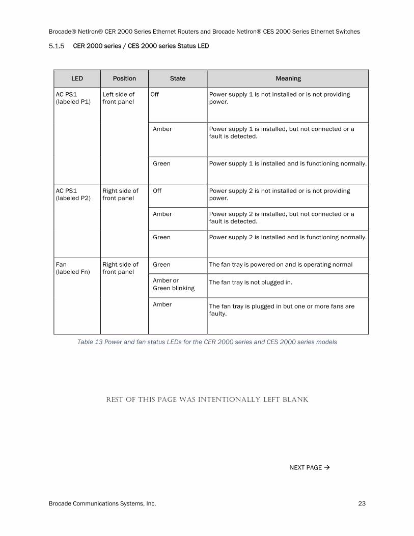
CER 2000 series / CES 2000 series Status LED
LED Position State Meaning
AC PS1 (labeled P1)
Left side of front panel
Off Power supply 1 is not installed or is not providing power.
Amber Power supply 1 is installed, but not connected or a fault is detected.
Green Power supply 1 is installed and is functioning normally.
AC PS1 (labeled P2)
Right side of front panel
Off Power supply 2 is not installed or is not providing power.
Amber Power supply 2 is installed, but not connected or a fault is detected.
Green Power supply 2 is installed and is functioning normally.
Fan (labeled Fn)
Right side of front panel
Green The fan tray is powered on and is operating normal
Amber or Green blinking
The fan tray is not plugged in.
Amber The fan tray is plugged in but one or more fans are faulty.
Table 13 Power and fan status LEDs for the CER 2000 series and CES 2000 series models
REST OF THIS PAGE WAS INTENTIONALLY LEFT BLANK
NEXT PAGE
Brocade® NetIron® CER 2000 Series Ethernet Routers and Brocade NetIron® CES 2000 Series Ethernet Switches
Brocade Communications Systems, Inc. 24
Modes of Operation
The NetIron validated cryptographic module has two modes of operation:
FIPS Approved mode and
Non-Approved mode.
Both these modes enforce digital signature based firmware load test. Section 6.2 {Services (Services in Approved mode)} and section 7 (Algorithm certificates) describe services and cryptographic algorithms available in FIPS Approved mode.
Section 9.2, FIPS Approved Mode, describes how to invoke FIPS Approved mode.
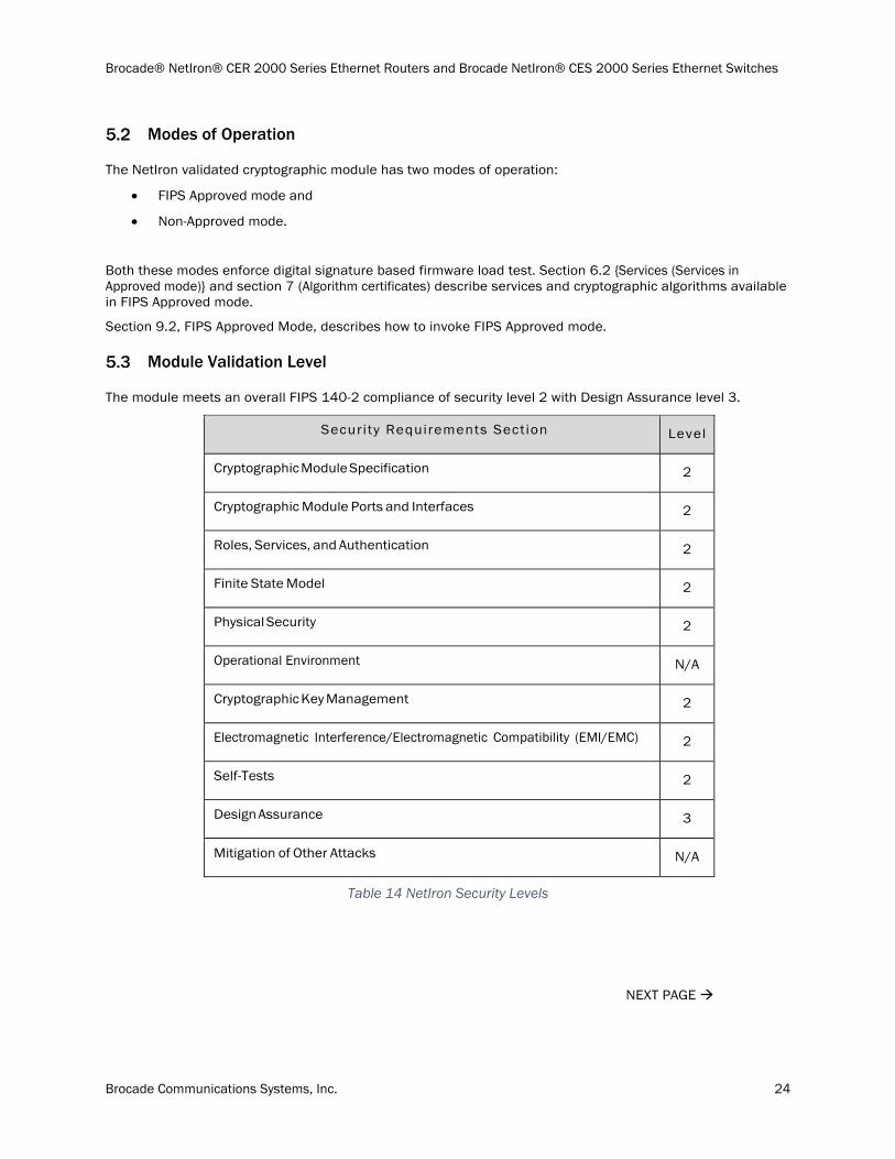
Module Validation Level
The module meets an overall FIPS 140-2 compliance of security level 2 with Design Assurance level 3.
Security Requirements Section Level
Cryptographic Module Specification 2
Cryptographic Module Ports and Interfaces 2
Roles, Services, and Authentication 2
Finite State Model 2
Physical Security 2
Operational Environment N/A
Cryptographic Key Management 2
Electromagnetic Interference/Electromagnetic Compatibility (EMI/EMC) 2
Self-Tests 2
Design Assurance 3
Mitigation of Other Attacks N/A
Table 14 NetIron Security Levels
NEXT PAGE
Brocade® NetIron® CER 2000 Series Ethernet Routers and Brocade NetIron® CES 2000 Series Ethernet Switches
Brocade Communications Systems, Inc. 25
Roles and Services
Roles
In FIPS Approved mode, NetIron devices support many different authenticated roles.
The Crypto-officer role
The Crypto-officer role on the device in FIPS Approved mode is equivalent to administrator or super-user in non-Approved mode. Hence, the Crypto-officer role has complete access to the system.
Port Configuration Administrator role
The Port Configuration Administrator role on the device in FIPS Approved mode is equivalent to the port-config, a port configuration user in non-Approved mode. Hence, the Port Configuration Administrator role has read-and-write access for specific ports but not for global (system-wide) parameters.
User role
The User role on the device in FIPS Approved mode has read-only privileges and no configuration mode access (user).
NTP Peer role
This role performs the NTP operation.
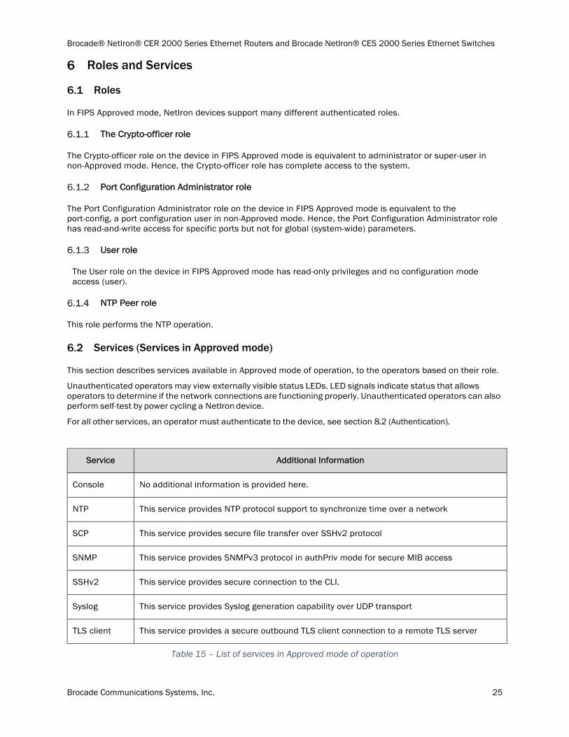
Services (Services in Approved mode)
This section describes services available in Approved mode of operation, to the operators based on their role.
Unauthenticated operators may view externally visible status LEDs. LED signals indicate status that allows operators to determine if the network connections are functioning properly. Unauthenticated operators can also perform self-test by power cycling a NetIron device.
For all other services, an operator must authenticate to the device, see section 8.2 (Authentication).
Service Additional Information
Console No additional information is provided here.
NTP This service provides NTP protocol support to synchronize time over a network
SCP This service provides secure file transfer over SSHv2 protocol
SNMP This service provides SNMPv3 protocol in authPriv mode for secure MIB access
SSHv2 This service provides secure connection to the CLI.
Syslog This service provides Syslog generation capability over UDP transport
TLS client This service provides a secure outbound TLS client connection to a remote TLS server
Table 15 – List of services in Approved mode of operation
Brocade® NetIron® CER 2000 Series Ethernet Routers and Brocade NetIron® CES 2000 Series Ethernet Switches
Brocade Communications Systems, Inc. 26
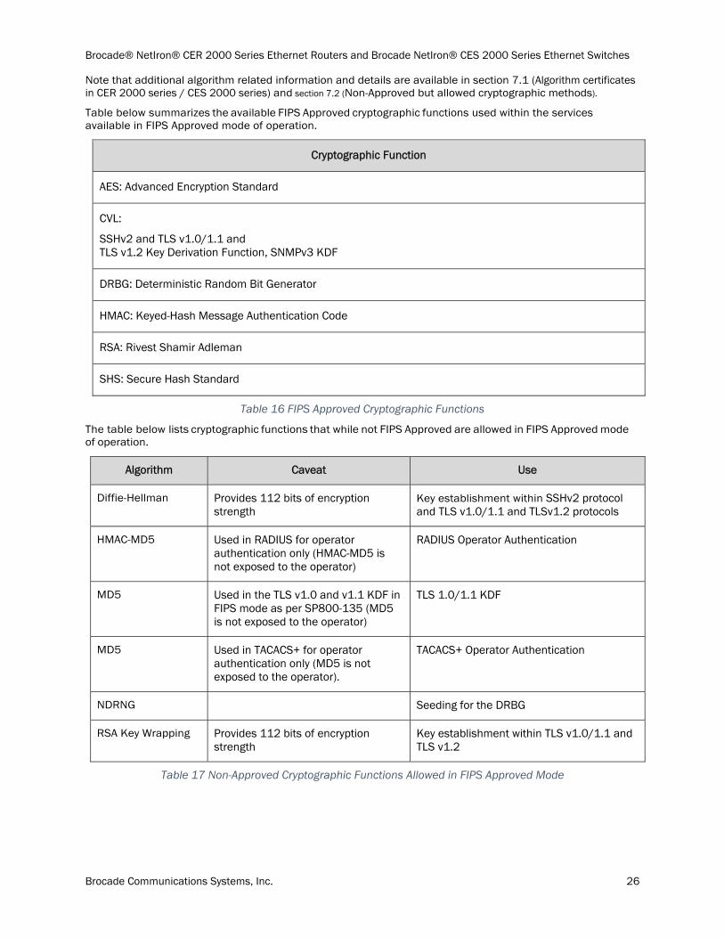
Note that additional algorithm related information and details are available in section 7.1 (Algorithm certificates in CER 2000 series / CES 2000 series) and section 7.2 (Non-Approved but allowed cryptographic methods).
Table below summarizes the available FIPS Approved cryptographic functions used within the services available in FIPS Approved mode of operation.
Cryptographic Function
AES: Advanced Encryption Standard
CVL:
SSHv2 and TLS v1.0/1.1 and TLS v1.2 Key Derivation Function, SNMPv3 KDF
DRBG: Deterministic Random Bit Generator
HMAC: Keyed-Hash Message Authentication Code
RSA: Rivest Shamir Adleman
SHS: Secure Hash Standard
Table 16 FIPS Approved Cryptographic Functions
The table below lists cryptographic functions that while not FIPS Approved are allowed in FIPS Approved mode of operation.
Algorithm Caveat Use
Diffie-Hellman Provides 112 bits of encryption strength
Key establishment within SSHv2 protocol and TLS v1.0/1.1 and TLSv1.2 protocols
HMAC-MD5 Used in RADIUS for operator authentication only (HMAC-MD5 is not exposed to the operator)
RADIUS Operator Authentication
MD5 Used in the TLS v1.0 and v1.1 KDF in FIPS mode as per SP800-135 (MD5 is not exposed to the operator)
TLS 1.0/1.1 KDF
MD5 Used in TACACS+ for operator authentication only (MD5 is not exposed to the operator).
TACACS+ Operator Authentication
NDRNG Seeding for the DRBG
RSA Key Wrapping Provides 112 bits of encryption strength
Key establishment within TLS v1.0/1.1 and TLS v1.2
Table 17 Non-Approved Cryptographic Functions Allowed in FIPS Approved Mode
Brocade® NetIron® CER 2000 Series Ethernet Routers and Brocade NetIron® CES 2000 Series Ethernet Switches
Brocade Communications Systems, Inc. 27
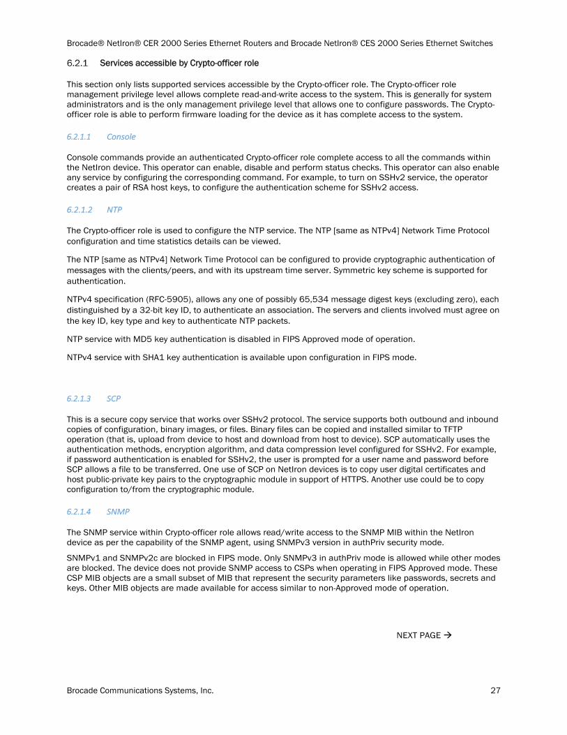
Services accessible by Crypto-officer role
This section only lists supported services accessible by the Crypto-officer role. The Crypto-officer role management privilege level allows complete read-and-write access to the system. This is generally for system administrators and is the only management privilege level that allows one to configure passwords. The Crypto-officer role is able to perform firmware loading for the device as it has complete access to the system.
6.2.1.1 Console
Console commands provide an authenticated Crypto-officer role complete access to all the commands within the NetIron device. This operator can enable, disable and perform status checks. This operator can also enable any service by configuring the corresponding command. For example, to turn on SSHv2 service, the operator creates a pair of RSA host keys, to configure the authentication scheme for SSHv2 access.
6.2.1.2 NTP
The Crypto-officer role is used to configure the NTP service. The NTP [same as NTPv4] Network Time Protocol configuration and time statistics details can be viewed.
The NTP [same as NTPv4] Network Time Protocol can be configured to provide cryptographic authentication of messages with the clients/peers, and with its upstream time server. Symmetric key scheme is supported for authentication.
NTPv4 specification (RFC-5905), allows any one of possibly 65,534 message digest keys (excluding zero), each distinguished by a 32-bit key ID, to authenticate an association. The servers and clients involved must agree on the key ID, key type and key to authenticate NTP packets.
NTP service with MD5 key authentication is disabled in FIPS Approved mode of operation.
NTPv4 service with SHA1 key authentication is available upon configuration in FIPS mode.
6.2.1.3 SCP
This is a secure copy service that works over SSHv2 protocol. The service supports both outbound and inbound copies of configuration, binary images, or files. Binary files can be copied and installed similar to TFTP operation (that is, upload from device to host and download from host to device). SCP automatically uses the authentication methods, encryption algorithm, and data compression level configured for SSHv2. For example, if password authentication is enabled for SSHv2, the user is prompted for a user name and password before SCP allows a file to be transferred. One use of SCP on NetIron devices is to copy user digital certificates and host public-private key pairs to the cryptographic module in support of HTTPS. Another use could be to copy configuration to/from the cryptographic module.
6.2.1.4 SNMP
The SNMP service within Crypto-officer role allows read/write access to the SNMP MIB within the NetIron device as per the capability of the SNMP agent, using SNMPv3 version in authPriv security mode.
SNMPv1 and SNMPv2c are blocked in FIPS mode. Only SNMPv3 in authPriv mode is allowed while other modes are blocked. The device does not provide SNMP access to CSPs when operating in FIPS Approved mode. These CSP MIB objects are a small subset of MIB that represent the security parameters like passwords, secrets and keys. Other MIB objects are made available for access similar to non-Approved mode of operation.
NEXT PAGE
Brocade® NetIron® CER 2000 Series Ethernet Routers and Brocade NetIron® CES 2000 Series Ethernet Switches
Brocade Communications Systems, Inc. 28
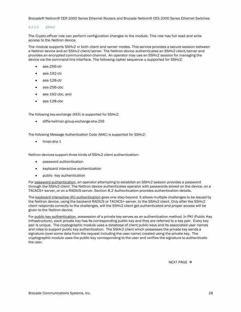
6.2.1.5 SSHv2
The Crypto-officer role can perform configuration changes to the module. This role has full read and write access to the NetIron device.
The module supports SSHv2 in both client and server modes. This service provides a secure session between a NetIron device and an SSHv2 client/server. The NetIron device authenticates an SSHv2 client/server and provides an encrypted communication channel. An operator may use an SSHv2 session for managing the device via the command line interface. The following cipher sequence is supported for SSHv2:
aes-256-ctr
aes-192-ctr
aes-128-ctr
aes-256-cbc
aes-192-cbc, and
aes-128-cbc
The following key-exchange (KEX) is supported for SSHv2:
diffie-hellman-group-exchange-sha-256
The following Message Authentication Code (MAC) is supported for SSHv2:
hmac-sha-1
NetIron devices support three kinds of SSHv2 client authentication:
password authentication
keyboard interactive authentication
public- key authentication
For password authentication, an operator attempting to establish an SSHv2 session provides a password through the SSHv2 client. The NetIron device authenticates operator with passwords stored on the device, on a TACACS+ server, or on a RADIUS server. Section 8.2 Authentication provides authentication details.
The keyboard interactive (KI) authentication goes one step beyond. It allows multiple challenges to be issued by the NetIron device, using the backend RADIUS or TACACS+ server, to the SSHv2 client. Only after the SSHv2 client responds correctly to the challenges, will the SSHv2 client get authenticated and proper access will be given to the NetIron device.
For public key authentication, possession of a private key serves as an authentication method. In PKI (Public Key Infrastructure), each private key has its corresponding public key and they are referred to a key pair. Every key pair is unique. The cryptographic module uses a database of client public keys and its associated user names and roles to support public key authentication. The SSHv2 client which possesses the private key sends a signature (over some data from the request including the user name) created using the private key. The cryptographic module uses the public key corresponding to the user and verifies the signature to authenticate the user.
NEXT PAGE

Brocade® NetIron® CER 2000 Series Ethernet Routers and Brocade NetIron® CES 2000 Series Ethernet Switches
Brocade Communications Systems, Inc. 29
6.2.1.6 Syslog
The Crypto-office can configure the syslog settings.
This service can be used to view the syslog configuration settings.
This service can be used to view the syslog audit records saved on the cryptographic module.
6.2.1.7 TLS client
This service can be used to configure and view statistics for following protocol operations:
OpenFlow.
o A peer Openflow controller device which establishes an OpenFlow connection with the cryptographic module. OpenFlow protocol allows external entity to control the behavior of the NetIron device by installing flows that affects the packet forwarding action of the device. This is the OpenFlow active mode of operation.
File Copy
o File copy command uses HTTP protocol over TLS transport to transfer files between the device and a HTTP server. NOTE: No device firmware image can be transferred to the device using this service.
The device uses TLS v1.0/1.1 and v1.2 with the following cipher suites:
TLS_RSA_WITH_AES_128_CBC_SHA
TLS_RSA_WITH_AES_256_CBC_SHA
TLS_RSA_WITH_AES_128_CBC_SHA256
TLS_RSA_WITH_AES_256_CBC_SHA256
TLS_DHE_RSA_WITH_AES_128_CBC_SHA
TLS_DHE_RSA_WITH_AES_256_CBC_SHA
TLS_DHE_RSA_WITH_AES_128_CBC_SHA256
TLS_DHE_RSA_WITH_AES_256_CBC_SHA256
Services accessible by Port Configuration Administrator role
This section only lists supported services accessible by Port Configuration Administrator. The Port Configuration Administrator role management privilege level allows read-and-write access for port configuration, but not for global (system-wide) parameters.
6.2.2.1 Console
Console access as the Port Configuration Administrator role provides an operator with the same capabilities as User role Console commands plus configuration commands associated with a network port on the device.
This service is described in Section 6.2.1.1 above.
6.2.2.2 NTP
The Port Configuration Administrator role can read the configuration for this service.
This service is described in Section 6.2.1.2 above.
Brocade® NetIron® CER 2000 Series Ethernet Routers and Brocade NetIron® CES 2000 Series Ethernet Switches
Brocade Communications Systems, Inc. 30
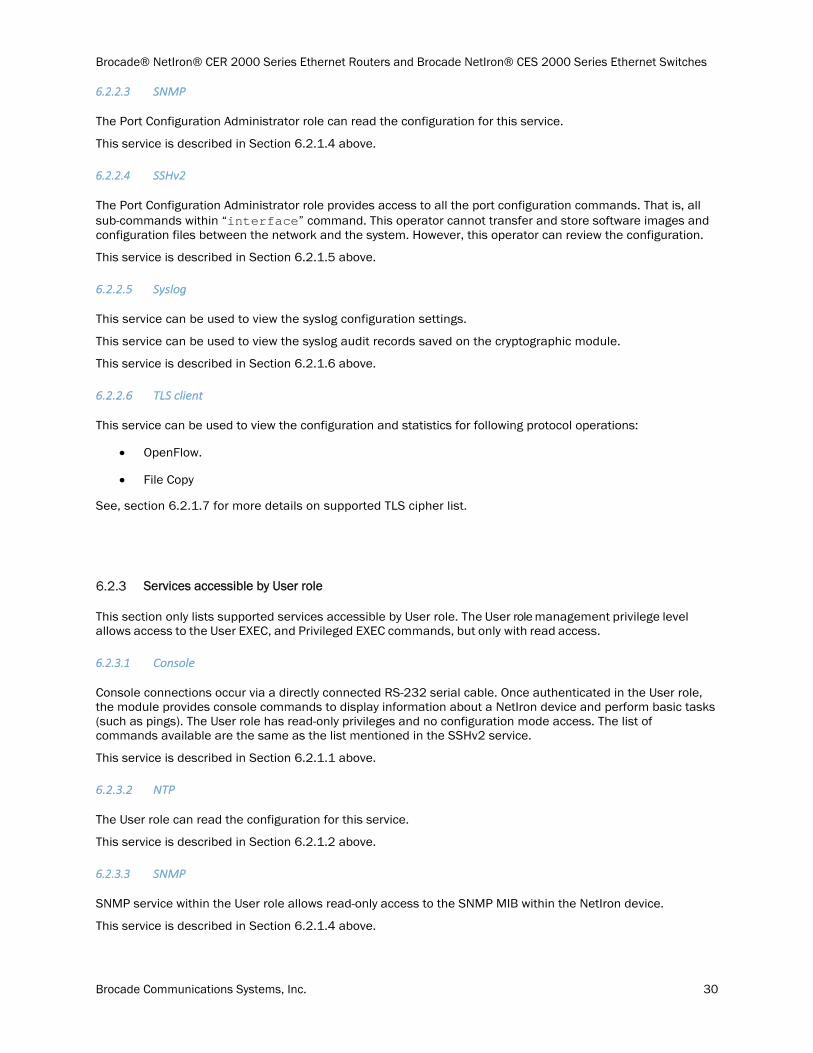
6.2.2.3 SNMP
The Port Configuration Administrator role can read the configuration for this service.
This service is described in Section 6.2.1.4 above.
6.2.2.4 SSHv2
The Port Configuration Administrator role provides access to all the port configuration commands. That is, all sub-commands within “interface” command. This operator cannot transfer and store software images and configuration files between the network and the system. However, this operator can review the configuration.
This service is described in Section 6.2.1.5 above.
6.2.2.5 Syslog
This service can be used to view the syslog configuration settings.
This service can be used to view the syslog audit records saved on the cryptographic module.
This service is described in Section 6.2.1.6 above.
6.2.2.6 TLS client
This service can be used to view the configuration and statistics for following protocol operations:
OpenFlow.
File Copy
See, section 6.2.1.7 for more details on supported TLS cipher list.
Services accessible by User role
This section only lists supported services accessible by User role. The User role management privilege level allows access to the User EXEC, and Privileged EXEC commands, but only with read access.
6.2.3.1 Console
Console connections occur via a directly connected RS-232 serial cable. Once authenticated in the User role, the module provides console commands to display information about a NetIron device and perform basic tasks (such as pings). The User role has read-only privileges and no configuration mode access. The list of commands available are the same as the list mentioned in the SSHv2 service.
This service is described in Section 6.2.1.1 above.
6.2.3.2 NTP
The User role can read the configuration for this service.
This service is described in Section 6.2.1.2 above.
6.2.3.3 SNMP
SNMP service within the User role allows read-only access to the SNMP MIB within the NetIron device.
This service is described in Section 6.2.1.4 above.

Brocade® NetIron® CER 2000 Series Ethernet Routers and Brocade NetIron® CES 2000 Series Ethernet Switches
Brocade Communications Systems, Inc. 31
6.2.3.4 SSHv2
The User role can only perform read operation.
This service is described in Section 6.2.1.5 above.
6.2.3.5 Syslog
This service can be used to view the syslog configuration settings.
This service can be used to view the syslog audit records saved on the cryptographic module.
This service is described in Section 6.2.1.6 above.
6.2.3.6 TLS client
This service can be used to view the configuration and statistics for following protocol operations:
OpenFlow.
File Copy
See, section 6.2.1.7 for more details on supported TLS cipher list.
Services accessible by NTP Peer role
This section only lists supported services accessible by NTP Peer role.
6.2.4.1 NTP
This service is described in Section 6.2.1.2 above.
This role utilizes the NTP service which implements the NTP protocol for time synchronization.
REST OF THIS PAGE WAS INTENTIONALLY LEFT BLANK
NEXT PAGE
Brocade® NetIron® CER 2000 Series Ethernet Routers and Brocade NetIron® CES 2000 Series Ethernet Switches
Brocade Communications Systems, Inc. 32
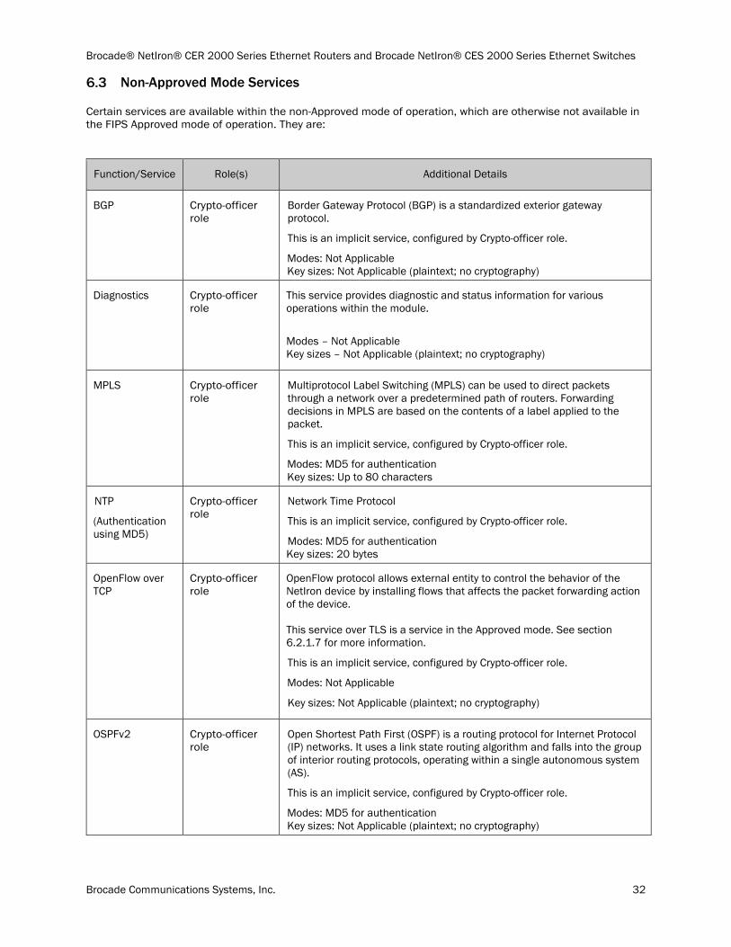
Non-Approved Mode Services
Certain services are available within the non-Approved mode of operation, which are otherwise not available in the FIPS Approved mode of operation. They are:
Function/Service Role(s) Additional Details
BGP Crypto-officer role
Border Gateway Protocol (BGP) is a standardized exterior gateway protocol.
This is an implicit service, configured by Crypto-officer role.
Modes: Not Applicable Key sizes: Not Applicable (plaintext; no cryptography)
Diagnostics Crypto-officer role
This service provides diagnostic and status information for various operations within the module.
Modes – Not Applicable Key sizes – Not Applicable (plaintext; no cryptography)
MPLS Crypto-officer role
Multiprotocol Label Switching (MPLS) can be used to direct packets through a network over a predetermined path of routers. Forwarding decisions in MPLS are based on the contents of a label applied to the packet.
This is an implicit service, configured by Crypto-officer role.
Modes: MD5 for authentication Key sizes: Up to 80 characters
NTP
(Authentication using MD5)
Crypto-officer role
Network Time Protocol
This is an implicit service, configured by Crypto-officer role.
Modes: MD5 for authentication Key sizes: 20 bytes
OpenFlow over TCP
Crypto-officer role
OpenFlow protocol allows external entity to control the behavior of the NetIron device by installing flows that affects the packet forwarding action of the device. This service over TLS is a service in the Approved mode. See section 6.2.1.7 for more information.
This is an implicit service, configured by Crypto-officer role.
Modes: Not Applicable
Key sizes: Not Applicable (plaintext; no cryptography)
OSPFv2 Crypto-officer role
Open Shortest Path First (OSPF) is a routing protocol for Internet Protocol (IP) networks. It uses a link state routing algorithm and falls into the group of interior routing protocols, operating within a single autonomous system (AS).
This is an implicit service, configured by Crypto-officer role.
Modes: MD5 for authentication Key sizes: Not Applicable (plaintext; no cryptography)
Brocade® NetIron® CER 2000 Series Ethernet Routers and Brocade NetIron® CES 2000 Series Ethernet Switches
Brocade Communications Systems, Inc. 33
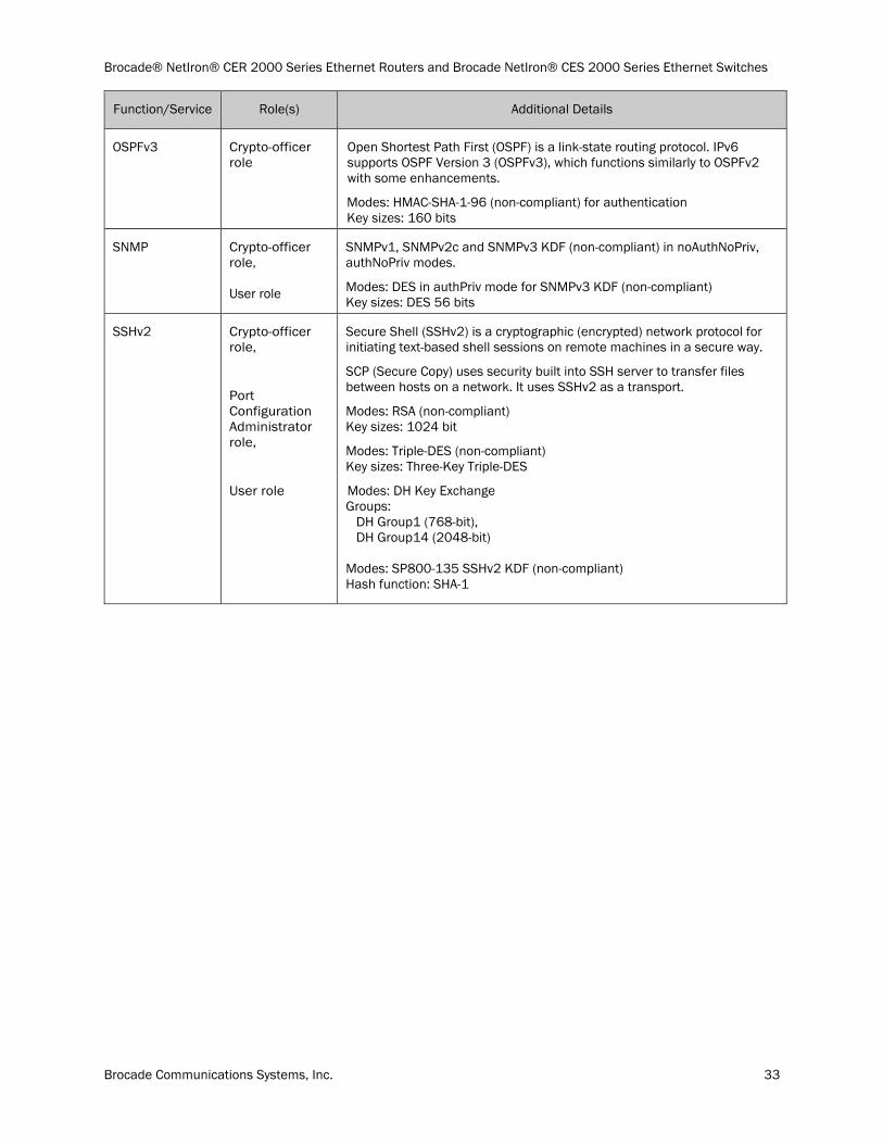
Function/Service Role(s) Additional Details
OSPFv3 Crypto-officer role
Open Shortest Path First (OSPF) is a link-state routing protocol. IPv6 supports OSPF Version 3 (OSPFv3), which functions similarly to OSPFv2 with some enhancements.
Modes: HMAC-SHA-1-96 (non-compliant) for authentication Key sizes: 160 bits
SNMP Crypto-officer role, User role
SNMPv1, SNMPv2c and SNMPv3 KDF (non-compliant) in noAuthNoPriv, authNoPriv modes.
Modes: DES in authPriv mode for SNMPv3 KDF (non-compliant) Key sizes: DES 56 bits
SSHv2 Crypto-officer role,
Port Configuration Administrator role,
User role
Secure Shell (SSHv2) is a cryptographic (encrypted) network protocol for initiating text-based shell sessions on remote machines in a secure way.
SCP (Secure Copy) uses security built into SSH server to transfer files between hosts on a network. It uses SSHv2 as a transport.
Modes: RSA (non-compliant) Key sizes: 1024 bit
Modes: Triple-DES (non-compliant) Key sizes: Three-Key Triple-DES
Modes: DH Key Exchange Groups: DH Group1 (768-bit), DH Group14 (2048-bit) Modes: SP800-135 SSHv2 KDF (non-compliant) Hash function: SHA-1
Brocade® NetIron® CER 2000 Series Ethernet Routers and Brocade NetIron® CES 2000 Series Ethernet Switches
Brocade Communications Systems, Inc. 34
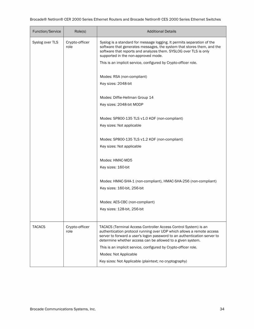
Function/Service Role(s) Additional Details
Syslog over TLS Crypto-officer role
Syslog is a standard for message logging. It permits separation of the software that generates messages, the system that stores them, and the software that reports and analyzes them. SYSLOG over TLS is only supported in the non-approved mode.
This is an implicit service, configured by Crypto-officer role.
Modes: RSA (non-compliant)
Key sizes: 2048-bit
Modes: Diffie-Hellman Group 14
Key sizes: 2048-bit MODP
Modes: SP800-135 TLS v1.0 KDF (non-compliant)
Key sizes: Not applicable
Modes: SP800-135 TLS v1.2 KDF (non-compliant)
Key sizes: Not applicable
Modes: HMAC-MD5
Key sizes: 160-bit
Modes: HMAC-SHA-1 (non-compliant), HMAC-SHA-256 (non-compliant)
Key sizes: 160-bit, 256-bit
Modes: AES-CBC (non-compliant)
Key sizes: 128-bit, 256-bit
TACACS Crypto-officer role
TACACS (Terminal Access Controller Access Control System) is an authentication protocol running over UDP which allows a remote access server to forward a user's logon password to an authentication server to determine whether access can be allowed to a given system.
This is an implicit service, configured by Crypto-officer role.
Modes: Not Applicable
Key sizes: Not Applicable (plaintext; no cryptography)
Brocade® NetIron® CER 2000 Series Ethernet Routers and Brocade NetIron® CES 2000 Series Ethernet Switches
Brocade Communications Systems, Inc. 35
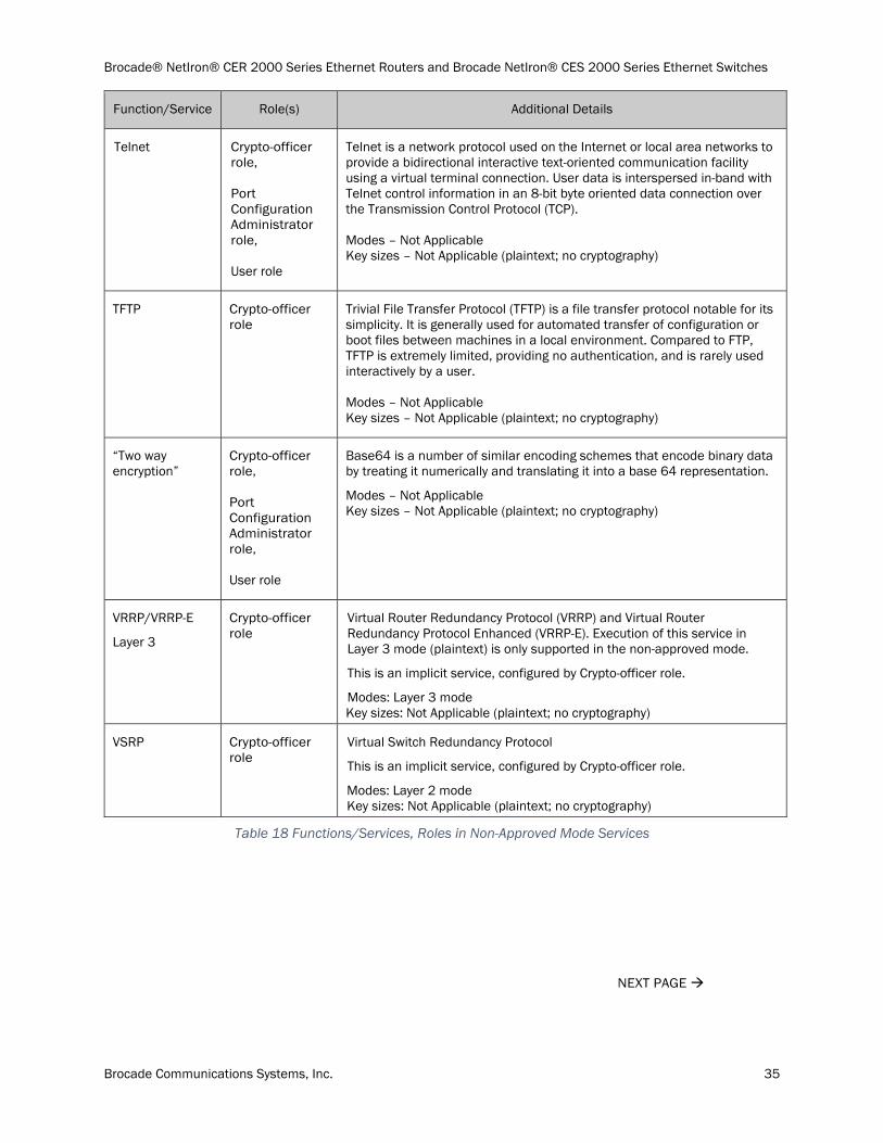
Function/Service Role(s) Additional Details
Telnet Crypto-officer role, Port Configuration Administrator role, User role
Telnet is a network protocol used on the Internet or local area networks to provide a bidirectional interactive text-oriented communication facility using a virtual terminal connection. User data is interspersed in-band with Telnet control information in an 8-bit byte oriented data connection over the Transmission Control Protocol (TCP). Modes – Not Applicable Key sizes – Not Applicable (plaintext; no cryptography)
TFTP Crypto-officer role
Trivial File Transfer Protocol (TFTP) is a file transfer protocol notable for its simplicity. It is generally used for automated transfer of configuration or boot files between machines in a local environment. Compared to FTP, TFTP is extremely limited, providing no authentication, and is rarely used interactively by a user. Modes – Not Applicable Key sizes – Not Applicable (plaintext; no cryptography)
“Two way encryption”
Crypto-officer role, Port Configuration Administrator role, User role
Base64 is a number of similar encoding schemes that encode binary data by treating it numerically and translating it into a base 64 representation.
Modes – Not Applicable Key sizes – Not Applicable (plaintext; no cryptography)
VRRP/VRRP-E
Layer 3
Crypto-officer role
Virtual Router Redundancy Protocol (VRRP) and Virtual Router Redundancy Protocol Enhanced (VRRP-E). Execution of this service in Layer 3 mode (plaintext) is only supported in the non-approved mode.
This is an implicit service, configured by Crypto-officer role.
Modes: Layer 3 mode Key sizes: Not Applicable (plaintext; no cryptography)
VSRP Crypto-officer role
Virtual Switch Redundancy Protocol
This is an implicit service, configured by Crypto-officer role.
Modes: Layer 2 mode Key sizes: Not Applicable (plaintext; no cryptography)
Table 18 Functions/Services, Roles in Non-Approved Mode Services
NEXT PAGE
Brocade® NetIron® CER 2000 Series Ethernet Routers and Brocade NetIron® CES 2000 Series Ethernet Switches
Brocade Communications Systems, Inc. 36
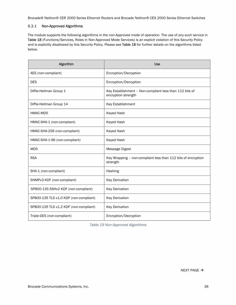
Non-Approved Algorithms
The module supports the following algorithms in the non-Approved mode of operation. The use of any such service in Table 18 (Functions/Services, Roles in Non-Approved Mode Services) is an explicit violation of this Security Policy and is explicitly disallowed by this Security Policy. Please see Table 18 for further details on the algorithms listed below:
Algorithm Use
AES (non-compliant) Encryption/Decryption
DES Encryption/Decryption
Diffie-Hellman Group 1 Key Establishment – Non-compliant less than 112 bits of encryption strength
Diffie-Hellman Group 14 Key Establishment
HMAC-MD5 Keyed Hash
HMAC-SHA-1 (non-compliant) Keyed Hash
HMAC-SHA-256 (non-compliant) Keyed Hash
HMAC-SHA-1-96 (non-compliant) Keyed Hash
MD5 Message Digest
RSA Key Wrapping – non-compliant less than 112 bits of encryption strength
SHA-1 (non-compliant) Hashing
SNMPv3 KDF (non-compliant) Key Derivation
SP800-135 SSHv2 KDF (non-compliant) Key Derivation
SP800-135 TLS v1.0 KDF (non-compliant) Key Derivation
SP800-135 TLS v1.2 KDF (non-compliant) Key Derivation
Triple-DES (non-compliant) Encryption/Decryption
Table 19 Non-Approved Algorithms
NEXT PAGE

Brocade® NetIron® CER 2000 Series Ethernet Routers and Brocade NetIron® CES 2000 Series Ethernet Switches
Brocade Communications Systems, Inc. 37
Brocade® NetIron® CER 2000 Series Ethernet Routers and Brocade NetIron® CES 2000 Series Ethernet Switches
Brocade Communications Systems, Inc. 38
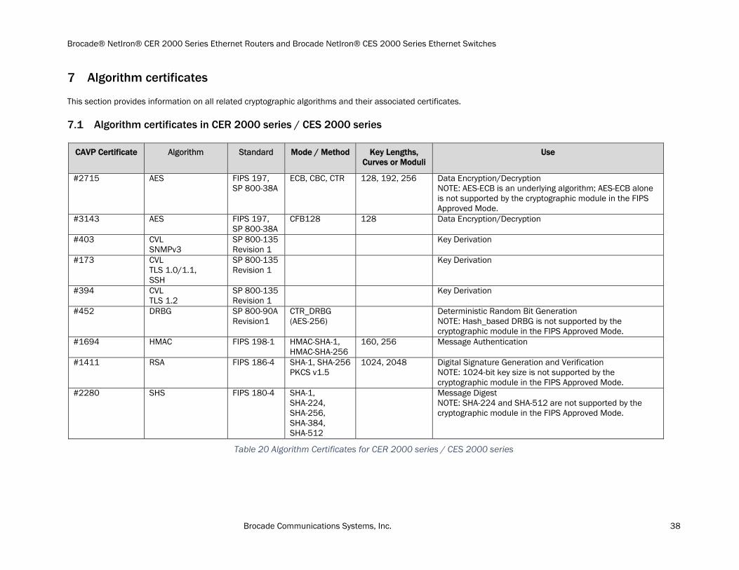
Algorithm certificates
This section provides information on all related cryptographic algorithms and their associated certificates.
Algorithm certificates in CER 2000 series / CES 2000 series
CAVP Certificate Algorithm Standard Mode / Method Key Lengths, Curves or Moduli
Use
#2715 AES
FIPS 197, SP 800-38A
ECB, CBC, CTR 128, 192, 256 Data Encryption/Decryption NOTE: AES-ECB is an underlying algorithm; AES-ECB alone is not supported by the cryptographic module in the FIPS Approved Mode.
#3143 AES FIPS 197, SP 800-38A
CFB128 128 Data Encryption/Decryption
#403 CVL SNMPv3
SP 800-135 Revision 1
Key Derivation
#173 CVL TLS 1.0/1.1, SSH
SP 800-135 Revision 1
Key Derivation
#394 CVL TLS 1.2
SP 800-135 Revision 1
Key Derivation
#452 DRBG SP 800-90A Revision1
CTR_DRBG (AES-256)
Deterministic Random Bit Generation NOTE: Hash_based DRBG is not supported by the cryptographic module in the FIPS Approved Mode.
#1694 HMAC FIPS 198-1 HMAC-SHA-1, HMAC-SHA-256
160, 256 Message Authentication
#1411 RSA FIPS 186-4 SHA-1, SHA-256 PKCS v1.5
1024, 2048 Digital Signature Generation and Verification NOTE: 1024-bit key size is not supported by the cryptographic module in the FIPS Approved Mode.
#2280 SHS FIPS 180-4 SHA-1, SHA-224, SHA-256, SHA-384, SHA-512
Message Digest NOTE: SHA-224 and SHA-512 are not supported by the cryptographic module in the FIPS Approved Mode.
Table 20 Algorithm Certificates for CER 2000 series / CES 2000 series
Brocade® NetIron® CER 2000 Series Ethernet Routers and Brocade NetIron® CES 2000 Series Ethernet Switches
Brocade Communications Systems, Inc. 39
Operators should reference the transition tables that will be available at the CMVP Web site http://csrc.nist.gov/groups/STM/cmvp/. The data in the tables will inform users of the risks associated with using a particular algorithm and a given key length.
NOTE: The module does not allow the use of 1024-bit RSA in the FIPS Approved mode of operation due to the SP800-131A transition effective January 1, 2014.
Non-Approved but allowed cryptographic methods
See Table 17 for additional information on Non-Approved Cryptographic Functions Allowed in FIPS Approved Mode.
REST OF THIS PAGE WAS INTENTIONALLY LEFT BLANK
NEXT PAGE
Brocade® NetIron® CER 2000 Series Ethernet Routers and Brocade NetIron® CES 2000 Series Ethernet Switches
Brocade Communications Systems, Inc. 40
Policies
Security Rules
The cryptographic module’s design corresponds to the cryptographic module’s security rules. This section documents the security rules enforced by the cryptographic module to implement the FIPS 140-2 Level 2 security requirements. After configuring a NetIron device to operate in FIPS Approved mode the Crypto-officer role must execute the “fips self-tests” command to validate the integrity of the firmware installed on the device. If an error is detected during the self-test, the error must be corrected prior to rebooting the device.
Security rules are as follows:
1) The cryptographic module provides role-based authentication.
2) Until the module is placed in a valid role, the operator does not have access to any Critical Security Parameters (CSPs).
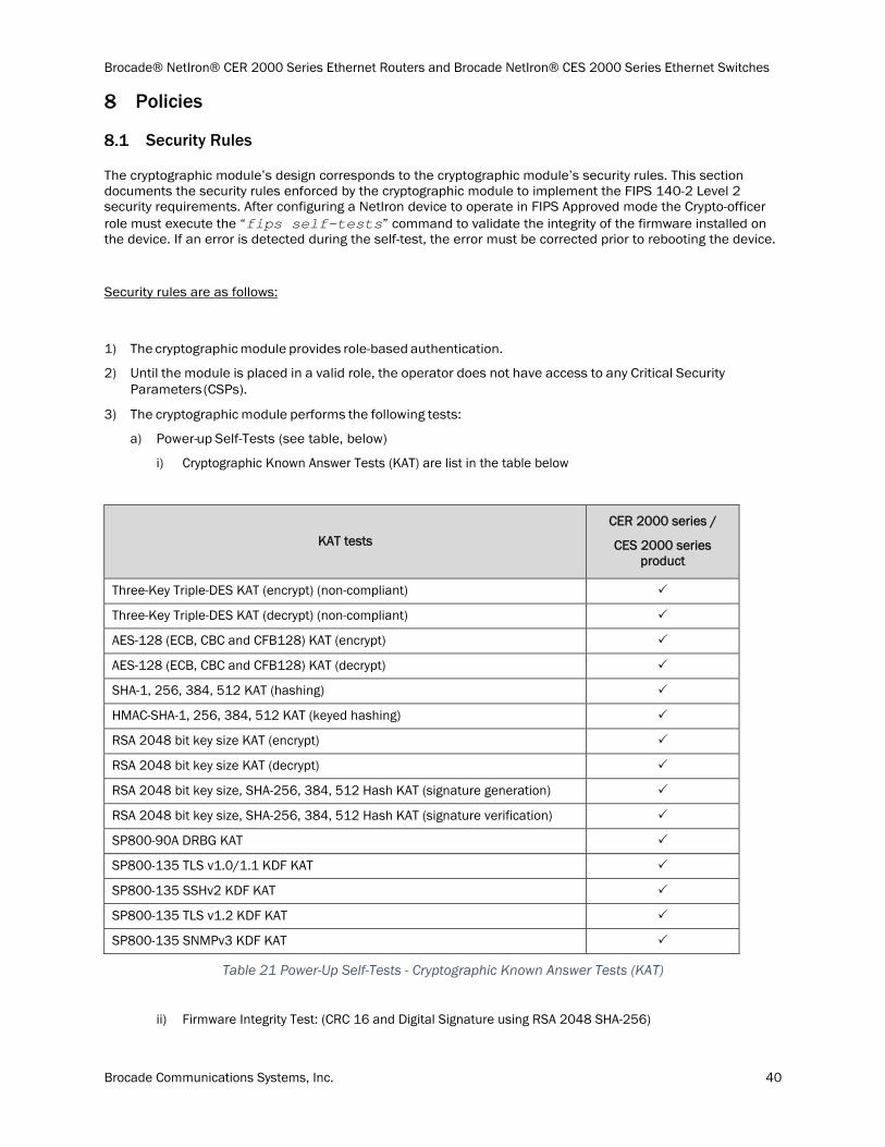
3) The cryptographic module performs the following tests:
a) Power-up Self-Tests (see table, below)
i) Cryptographic Known Answer Tests (KAT) are list in the table below
KAT tests
CER 2000 series /
CES 2000 series product
Three-Key Triple-DES KAT (encrypt) (non-compliant)
Three-Key Triple-DES KAT (decrypt) (non-compliant)
AES-128 (ECB, CBC and CFB128) KAT (encrypt)
AES-128 (ECB, CBC and CFB128) KAT (decrypt)
SHA-1, 256, 384, 512 KAT (hashing)
HMAC-SHA-1, 256, 384, 512 KAT (keyed hashing)
RSA 2048 bit key size KAT (encrypt)
RSA 2048 bit key size KAT (decrypt)
RSA 2048 bit key size, SHA-256, 384, 512 Hash KAT (signature generation)
RSA 2048 bit key size, SHA-256, 384, 512 Hash KAT (signature verification)
SP800-90A DRBG KAT
SP800-135 TLS v1.0/1.1 KDF KAT
SP800-135 SSHv2 KDF KAT
SP800-135 TLS v1.2 KDF KAT
SP800-135 SNMPv3 KDF KAT
Table 21 Power-Up Self-Tests - Cryptographic Known Answer Tests (KAT)
ii) Firmware Integrity Test: (CRC 16 and Digital Signature using RSA 2048 SHA-256)
Brocade® NetIron® CER 2000 Series Ethernet Routers and Brocade NetIron® CES 2000 Series Ethernet Switches
Brocade Communications Systems, Inc. 41
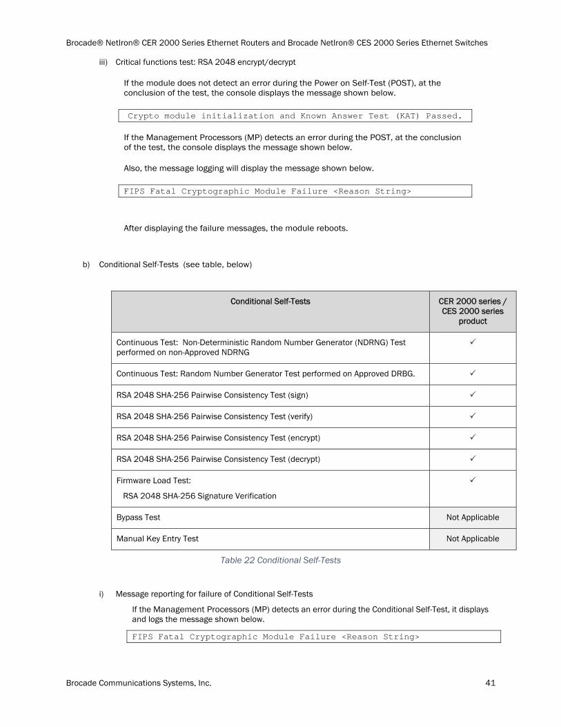
iii) Critical functions test: RSA 2048 encrypt/decrypt
If the module does not detect an error during the Power on Self-Test (POST), at the conclusion of the test, the console displays the message shown below.
Crypto module initialization and Known Answer Test (KAT) Passed.
If the Management Processors (MP) detects an error during the POST, at the conclusion of the test, the console displays the message shown below.
Also, the message logging will display the message shown below.
FIPS Fatal Cryptographic Module Failure <Reason String>
After displaying the failure messages, the module reboots.
b) Conditional Self-Tests (see table, below)
Conditional Self-Tests CER 2000 series / CES 2000 series
product
Continuous Test: Non-Deterministic Random Number Generator (NDRNG) Test performed on non-Approved NDRNG
Continuous Test: Random Number Generator Test performed on Approved DRBG.
RSA 2048 SHA-256 Pairwise Consistency Test (sign)
RSA 2048 SHA-256 Pairwise Consistency Test (verify)
RSA 2048 SHA-256 Pairwise Consistency Test (encrypt)
RSA 2048 SHA-256 Pairwise Consistency Test (decrypt)
Firmware Load Test:
RSA 2048 SHA-256 Signature Verification
Bypass Test Not Applicable
Manual Key Entry Test Not Applicable
Table 22 Conditional Self-Tests
i) Message reporting for failure of Conditional Self-Tests
If the Management Processors (MP) detects an error during the Conditional Self-Test, it displays and logs the message shown below.
FIPS Fatal Cryptographic Module Failure <Reason String>

Brocade® NetIron® CER 2000 Series Ethernet Routers and Brocade NetIron® CES 2000 Series Ethernet Switches
Brocade Communications Systems, Inc. 42
After displaying the failure message, the module reboots.
4) At any time the cryptographic module is in an idle state, the operator can command the module to perform the power-up self-test by executing the “fips self-tests” command.
5) Data output to services defined in section 6.2 is inhibited during key generation, self-tests, zeroization, and error states.
6) Status information does not contain CSPs or sensitive data that if used could compromise the module.
7) The following protocols have not been reviewed or tested by the CAVP nor CMVP:
a) TLS v1.0/1.1
b) SSHv2
c) TLS v1.2
d) SNMPv3
Cryptographic Module Operational Rules
In order to operate an CER 2000 series and CES 2000 series device securely, an operator should be aware of the following rules for FIPS Approved mode of operation.
Do not make external communication channels/ports available before initialization of an CER 2000 series and CES 2000 series device.
CER 2000 series and CES 2000 series devices implement FIPS Approved SP800-90A Deterministic Random Bit Generator (DRBG) in Counter (CTR) Mode.
CER 2000 series and CES 2000 series devices use FIPS Approved key generation methods:
RSA public and private keys
CER 2000 series and CES 2000 series devices restrict key entry and key generation to authenticated roles.
REST OF THIS PAGE WAS INTENTIONALLY LEFT BLANK
NEXT PAGE
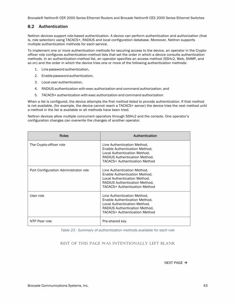
Brocade® NetIron® CER 2000 Series Ethernet Routers and Brocade NetIron® CES 2000 Series Ethernet Switches
Brocade Communications Systems, Inc. 43
Authentication
NetIron devices support role-based authentication. A device can perform authentication and authorization (that is, role selection) using TACACS+, RADIUS and local configuration database. Moreover, NetIron supports multiple authentication methods for each service.
To implement one or more authentication methods for securing access to the device, an operator in the Crypto- officer role configures authentication-method lists that set the order in which a device consults authentication methods. In an authentication-method list, an operator specifies an access method (SSHv2, Web, SNMP, and so on) and the order in which the device tries one or more of the following authentication methods:
1. Line password authentication,
2. Enable password authentication,
3. Local user authentication,
4. RADIUS authentication with exec authorization and command authorization, and
5. TACACS+ authentication with exec authorization and command authorization
When a list is configured, the device attempts the first method listed to provide authentication. If that method is not available, (for example, the device cannot reach a TACACS+ server) the device tries the next method until a method in the list is available or all methods have been tried.
NetIron devices allow multiple concurrent operators through SSHv2 and the console. One operator’s configuration changes can overwrite the changes of another operator.
Roles Authentication
The Crypto-officer role Line Authentication Method, Enable Authentication Method, Local Authentication Method, RADIUS Authentication Method, TACACS+ Authentication Method
Port Configuration Administrator role Line Authentication Method, Enable Authentication Method, Local Authentication Method, RADIUS Authentication Method, TACACS+ Authentication Method
User role Line Authentication Method, Enable Authentication Method, Local Authentication Method, RADIUS Authentication Method, TACACS+ Authentication Method
NTP Peer role Pre-shared key
Table 23 - Summary of authentication methods available for each role
REST OF THIS PAGE WAS INTENTIONALLY LEFT BLANK
NEXT PAGE
Brocade® NetIron® CER 2000 Series Ethernet Routers and Brocade NetIron® CES 2000 Series Ethernet Switches
Brocade Communications Systems, Inc. 44
Line Authentication Method
The line method uses the Telnet password to authenticate an operator.
To use line authentication, a Crypto-officer role must set the Telnet password. Please note that when operating in FIPS Approved mode, Telnet is disabled and Line Authentication is not available.
Enable Authentication Method
The enable method uses a password corresponding to each role to authenticate an operator. An operator must enter the read-only password to select the User role. An operator enters the port-config password to the Port Configuration Administrator role. An operator enters the super-user password to select the Crypto-officer role.
To use enable authentication, a Crypto-officer role must set the password for each privilege level.
Local Authentication Method
The local method uses a password associated with a user name to authenticate an operator. An operator enters a user name and corresponding password. The NetIron device assigns the role associated with the user name to the operator when authentication is successful.
To use local authentication, a Crypto-officer role must define user accounts. The definition includes a user name, password, and privilege level (which determines role).
RADIUS Authentication Method
The RADIUS method uses one or more RADIUS servers to verify user names and passwords. The NetIron device prompts an operator for user name and password. The device sends the user name and password to the RADIUS server. Upon successful authentication, the RADIUS server returns the operator’s privilege level, which determines the operator’s role. If a RADIUS server does not respond, the NetIron device will send the user name and password information to the next configured RADIUS server.
NetIron series devices support additional command authorization with RADIUS authentication. The following events occur when RADIUS command authorization takes place.
1. A user previously authenticated by a RADIUS server enters a command on the NetIron device.
2. The NetIron device looks at its configuration to see if the command is at a privilege level that requires RADIUS command authorization.
3. If the command belongs to a privilege level that requires authorization, the NetIron device looks at the list of commands returned to it when RADIUS server authenticated the user.
NOTE: After RADIUS authentication takes place, the command list resides on the NetIron device. The device does not consult the RADIUS server again once the operator has been authenticated. This means that any changes made to the operator’s command list on the RADIUS server are not reflected until the next time the RADIUS server authenticates the operator, and the server sends a new command list to the NetIron device.
To use RADIUS authentication, a Crypto-officer role must configure RADIUS server settings along with authentication and authorization settings.
TACACS+ Authentication Method
The TACACS+ methods use one or more TACACS+ servers to verify user names and passwords. For TACACS+, the NetIron device prompts an operator for user name and password. The device sends the user name and password to the TACACS+ server. Upon successful authentication, the NetIron device selects the operator’s role implicitly based on the action requested (for example, User role for a login request or Crypto-officer role for a configure terminal command). For TACACS+ authentication, the NetIron device prompts an operator for a user name, which the device uses to get a password prompt from the TACACS+ server. The operator enters a password, which the device relays to the server for validation. Upon successful authentication, the TACACS+ server supports both exec and command authorization similar to RADIUS authorization described above.

Brocade® NetIron® CER 2000 Series Ethernet Routers and Brocade NetIron® CES 2000 Series Ethernet Switches
Brocade Communications Systems, Inc. 45
To use TACACS+ authentication, a Crypto-officer role must configure TACACS+ server settings along with authentication and authorization settings.
Strength of Authentication
This section describes the strength of each authentication method
NetIron devices minimize the likelihood that a random authentication attempt will succeed. The module supports minimum 8 character passwords selected from the following character set: digits (Qty. 10), lowercase (Qty. 26) and uppercase (Qty. 26) letters, and punctuation marks (Qty. 18), for a total of 80 characters. Therefore, the probability of a successful random attempt is 1/80^8, which is less than 1/1,000,000.
The module enforces a one second delay for each attempted password verification, therefore the maximum number of random attempts per minute is 60. Thus, the probability of a successful random attempt within a one minute period is 60/80^8, which is less than 1/100,000.
RADIUS and TACACS+ support minimum 8 character passwords selected from the following character set: digits (Qty. 10), lowercase (Qty. 26) and uppercase (Qty. 26) letters, and punctuation marks (Qty. 18), for a total of 80 characters. Therefore, the probability of a successful random attempt is 1/80^8, which is less than 1/1,000,000.
A user gets three attempts before lockdown. When lockdown occurs, the user is locked out until the device is rebooted. Rebooting takes longer than one minute. Therefore, the maximum number of attempts per minute is 3. Thus, the probability of a successful random attempt within a one minute period is 3/80^8, which is less than 1/100,000.
For the NTP secret, the module supports minimum 8 character and maximum 16 character passwords selected from the following character set: digits (Qty. 10), lowercase (Qty. 26) and uppercase (Qty. 26) letters, and punctuation marks (Qty. 18) in passwords. Therefore the probability of a random attempt is 1/ 80^8 which is less than 1/1,000,000.
The module can process 1 authentication packet per 10 msec. Therefore, the probability of multiple consecutive attempts within a one minute period is 6000/80^8 which is less than 1/100,000.
REST OF THIS PAGE WAS INTENTIONALLY LEFT BLANK
NEXT PAGE
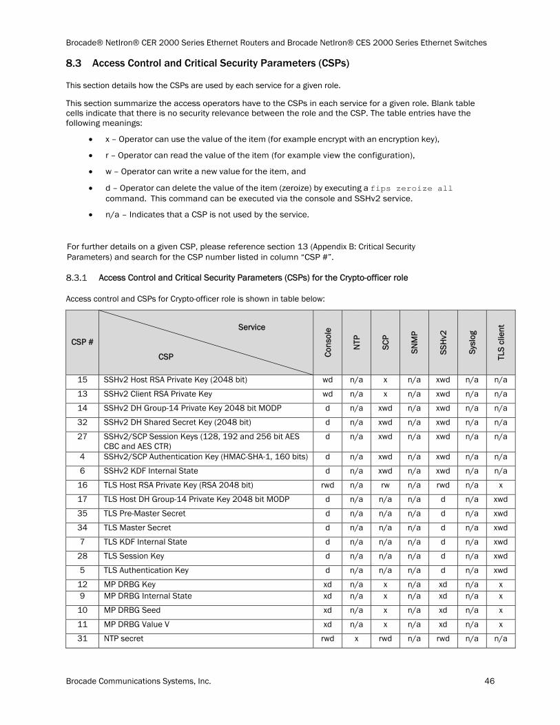
Brocade® NetIron® CER 2000 Series Ethernet Routers and Brocade NetIron® CES 2000 Series Ethernet Switches
Brocade Communications Systems, Inc. 46
Access Control and Critical Security Parameters (CSPs)
This section details how the CSPs are used by each service for a given role.
This section summarize the access operators have to the CSPs in each service for a given role. Blank table cells indicate that there is no security relevance between the role and the CSP. The table entries have the following meanings:
x – Operator can use the value of the item (for example encrypt with an encryption key),
r – Operator can read the value of the item (for example view the configuration),
w – Operator can write a new value for the item, and
d – Operator can delete the value of the item (zeroize) by executing a fips zeroize all command. This command can be executed via the console and SSHv2 service.
n/a – Indicates that a CSP is not used by the service.
For further details on a given CSP, please reference section 13 (Appendix B: Critical Security Parameters) and search for the CSP number listed in column “CSP #”.
Access Control and Critical Security Parameters (CSPs) for the Crypto-officer role
Access control and CSPs for Crypto-officer role is shown in table below:
CSP #
Service
CSP Cons
ole
NTP
SCP
SNM
P
SSH
v2
Sysl
og
TLS
clie
nt
15 SSHv2 Host RSA Private Key (2048 bit) wd n/a x n/a xwd n/a n/a
13 SSHv2 Client RSA Private Key wd n/a x n/a xwd n/a n/a
14 SSHv2 DH Group-14 Private Key 2048 bit MODP d n/a xwd n/a xwd n/a n/a
32 SSHv2 DH Shared Secret Key (2048 bit) d n/a xwd n/a xwd n/a n/a
27 SSHv2/SCP Session Keys (128, 192 and 256 bit AES CBC and AES CTR)
d n/a xwd n/a xwd n/a n/a
4 SSHv2/SCP Authentication Key (HMAC-SHA-1, 160 bits) d n/a xwd n/a xwd n/a n/a
6 SSHv2 KDF Internal State d n/a xwd n/a xwd n/a n/a
16 TLS Host RSA Private Key (RSA 2048 bit) rwd n/a rw n/a rwd n/a x
17 TLS Host DH Group-14 Private Key 2048 bit MODP d n/a n/a n/a d n/a xwd
35 TLS Pre-Master Secret d n/a n/a n/a d n/a xwd
34 TLS Master Secret d n/a n/a n/a d n/a xwd
7 TLS KDF Internal State d n/a n/a n/a d n/a xwd
28 TLS Session Key d n/a n/a n/a d n/a xwd
5 TLS Authentication Key d n/a n/a n/a d n/a xwd
12 MP DRBG Key xd n/a x n/a xd n/a x 9 MP DRBG Internal State xd n/a x n/a xd n/a x
10 MP DRBG Seed xd n/a x n/a xd n/a x
11 MP DRBG Value V xd n/a x n/a xd n/a x
31 NTP secret rwd x rwd n/a rwd n/a n/a
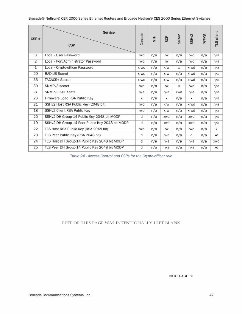
Brocade® NetIron® CER 2000 Series Ethernet Routers and Brocade NetIron® CES 2000 Series Ethernet Switches
Brocade Communications Systems, Inc. 47
CSP #
Service
CSP Cons
ole
NTP
SCP
SNM
P
SSH
v2
Sysl
og
TLS
clie
nt
3 Local - User Password rwd n/a rw n/a rwd n/a n/a
2 Local - Port Administrator Password rwd n/a rw n/a rwd n/a n/a
1 Local - Crypto-officer Password xrwd n/a xrw x xrwd n/a n/a
29 RADIUS Secret xrwd n/a xrw n/a xrwd n/a n/a
33 TACACS+ Secret xrwd n/a xrw n/a xrwd n/a n/a
30 SNMPv3 secret rwd n/a rw x rwd n/a n/a
8 SNMPv3 KDF State n/a n/a n/a xwd n/a n/a n/a
26 Firmware Load RSA Public Key x n/a x n/a x n/a n/a
21 SSHv2 Host RSA Public Key (2048 bit) rwd n/a xrw n/a xrwd n/a n/a
18 SSHv2 Client RSA Public Key rwd n/a xrw n/a xrwd n/a n/a
20 SSHv2 DH Group-14 Public Key 2048 bit MODP d n/a xwd n/a xwd n/a n/a
19 SSHv2 DH Group-14 Peer Public Key 2048 bit MODP d n/a xwd n/a xwd n/a n/a
22 TLS Host RSA Public Key (RSA 2048 bit) rwd n/a rw n/a rwd n/a x
23 TLS Peer Public Key (RSA 2048 bit) d n/a n/a n/a d n/a xd
24 TLS Host DH Group-14 Public Key 2048 bit MODP d n/a n/a n/a n/a n/a xwd
25 TLS Peer DH Group-14 Public Key 2048 bit MODP d n/a n/a n/a n/a n/a xd
Table 24 - Access Control and CSPs for the Crypto-officer role
REST OF THIS PAGE WAS INTENTIONALLY LEFT BLANK
NEXT PAGE

Brocade® NetIron® CER 2000 Series Ethernet Routers and Brocade NetIron® CES 2000 Series Ethernet Switches
Brocade Communications Systems, Inc. 48
Access Control and Critical Security Parameters (CSPs) for Port Configuration Administrator role
Access control and CSPs for Port Configuration Administrator role is shown in table below:
CSP #
Service
CSP Cons
ole
NTP
SNM
P
SSH
v2
Sysl
og
TLS
clie
nt
15 SSHv2 Host RSA Private Key (2048 bit) n/a n/a n/a x n/a n/a
13 SSHv2 Client RSA Private Key n/a n/a n/a x n/a n/a
14 SSHv2 DH Group-14 Private Key 2048 bit MODP n/a n/a n/a xwd n/a n/a
32 SSHv2 DH Shared Secret Key (2048 bit) n/a n/a n/a xwd n/a n/a
27 SSHv2/SCP Session Keys (128, 192 and 256 bit AES CBC and AES CTR)
n/a n/a n/a xwd n/a n/a
4 SSHv2/SCP Authentication Key (HMAC-SHA-1, 160 bits) n/a n/a n/a xwd n/a n/a
6 SSHv2 KDF Internal State n/a n/a n/a xwd n/a n/a
16 TLS Host RSA Private Key (RSA 2048 bit) n/a n/a n/a n/a n/a x
17 TLS Host DH Group-14 Private Key 2048 bit MODP n/a n/a n/a n/a n/a xwd
35 TLS Pre-Master Secret n/a n/a n/a n/a n/a xwd
34 TLS Master Secret~ n/a n/a n/a n/a n/a xwd
7 TLS KDF Internal State n/a n/a n/a n/a n/a xwd
28 TLS Session Key n/a n/a n/a n/a n/a xwd
5 TLS Authentication Key n/a n/a n/a n/a n/a xwd
12 MP DRBG Key n/a n/a n/a x n/a n/a
9 MP DRBG Internal State n/a n/a n/a x n/a n/a
10 MP DRBG Seed n/a n/a n/a x n/a n/a
11 MP DRBG Value V n/a n/a n/a x n/a n/a
31 NTP secret n/a n/a n/a n/a n/a n/a
3 Local - User Password n/a n/a n/a n/a n/a n/a
2 Local - Port Administrator Password x n/a n/a x n/a n/a
1 Local - Crypto-officer Password n/a n/a n/a n/a n/a n/a
29 RADIUS Secret n/a n/a n/a n/a n/a n/a
33 TACACS+ Secret n/a n/a n/a n/a n/a n/a
30 SNMPv3 secret n/a n/a n/a n/a n/a n/a
8 SNMPv3 KDF State n/a n/a n/a n/a n/a n/a
26 Firmware Load RSA Public Key n/a n/a n/a n/a n/a n/a
21 SSHv2 Host RSA Public Key (2048 bit) r n/a n/a xr n/a n/a
18 SSHv2 Client RSA Public Key r n/a n/a xr n/a n/a
20 SSHv2 DH Group-14 Public Key 2048 bit MODP n/a n/a n/a xwd n/a n/a
19 SSHv2 DH Group-14 Peer Public Key 2048 bit MODP n/a n/a n/a xd n/a n/a
22 TLS Host RSA Public Key (RSA 2048 bit) n/a n/a n/a n/a n/a x
23 TLS Peer Public Key (RSA 2048 bit) n/a n/a n/a n/a n/a x
24 TLS Host DH Group-14 Public Key 2048 bit MODP n/a n/a n/a n/a n/a xwd
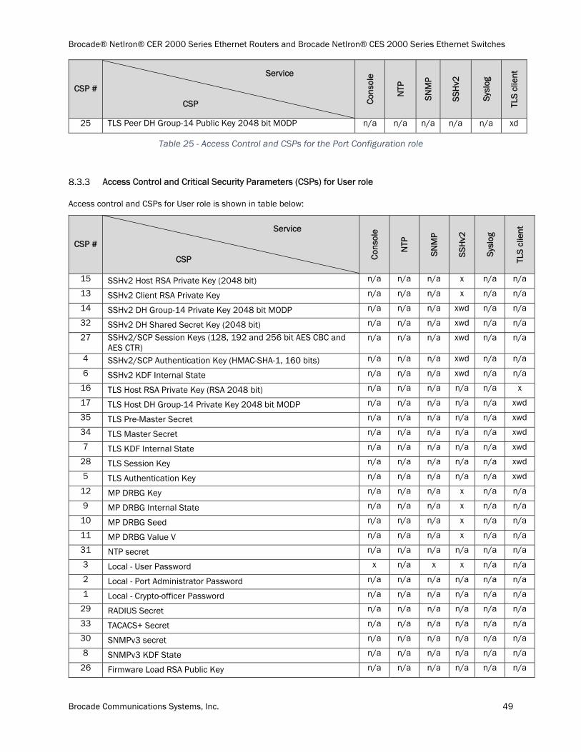
Brocade® NetIron® CER 2000 Series Ethernet Routers and Brocade NetIron® CES 2000 Series Ethernet Switches
Brocade Communications Systems, Inc. 49
CSP #
Service
CSP Cons
ole
NTP
SNM
P
SSH
v2
Sysl
og
TLS
clie
nt
25 TLS Peer DH Group-14 Public Key 2048 bit MODP n/a n/a n/a n/a n/a xd
Table 25 - Access Control and CSPs for the Port Configuration role
Access Control and Critical Security Parameters (CSPs) for User role
Access control and CSPs for User role is shown in table below:
CSP #
Service
CSP Cons
ole
NTP
SNM
P
SSH
v2
Sysl
og
TLS
clie
nt
15 SSHv2 Host RSA Private Key (2048 bit) n/a n/a n/a x n/a n/a
13 SSHv2 Client RSA Private Key n/a n/a n/a x n/a n/a
14 SSHv2 DH Group-14 Private Key 2048 bit MODP n/a n/a n/a xwd n/a n/a
32 SSHv2 DH Shared Secret Key (2048 bit) n/a n/a n/a xwd n/a n/a
27 SSHv2/SCP Session Keys (128, 192 and 256 bit AES CBC and AES CTR)
n/a n/a n/a xwd n/a n/a
4 SSHv2/SCP Authentication Key (HMAC-SHA-1, 160 bits) n/a n/a n/a xwd n/a n/a
6 SSHv2 KDF Internal State n/a n/a n/a xwd n/a n/a
16 TLS Host RSA Private Key (RSA 2048 bit) n/a n/a n/a n/a n/a x
17 TLS Host DH Group-14 Private Key 2048 bit MODP n/a n/a n/a n/a n/a xwd
35 TLS Pre-Master Secret n/a n/a n/a n/a n/a xwd
34 TLS Master Secret n/a n/a n/a n/a n/a xwd
7 TLS KDF Internal State n/a n/a n/a n/a n/a xwd
28 TLS Session Key n/a n/a n/a n/a n/a xwd
5 TLS Authentication Key n/a n/a n/a n/a n/a xwd
12 MP DRBG Key n/a n/a n/a x n/a n/a
9 MP DRBG Internal State n/a n/a n/a x n/a n/a
10 MP DRBG Seed n/a n/a n/a x n/a n/a
11 MP DRBG Value V n/a n/a n/a x n/a n/a
31 NTP secret n/a n/a n/a n/a n/a n/a
3 Local - User Password x n/a x x n/a n/a
2 Local - Port Administrator Password n/a n/a n/a n/a n/a n/a
1 Local - Crypto-officer Password n/a n/a n/a n/a n/a n/a
29 RADIUS Secret n/a n/a n/a n/a n/a n/a
33 TACACS+ Secret n/a n/a n/a n/a n/a n/a
30 SNMPv3 secret n/a n/a n/a n/a n/a n/a
8 SNMPv3 KDF State n/a n/a n/a n/a n/a n/a
26 Firmware Load RSA Public Key n/a n/a n/a n/a n/a n/a

Brocade® NetIron® CER 2000 Series Ethernet Routers and Brocade NetIron® CES 2000 Series Ethernet Switches
Brocade Communications Systems, Inc. 50
CSP #
Service
CSP Cons
ole
NTP
SNM
P
SSH
v2
Sysl
og
TLS
clie
nt
21 SSHv2 Host RSA Public Key (2048 bit) r n/a n/a xr n/a n/a
18 SSHv2 Client RSA Public Key r n/a n/a xr n/a n/a
20 SSHv2 DH Group-14 Public Key 2048 bit MODP n/a n/a n/a xwd n/a n/a
19 SSHv2 DH Group-14 Peer Public Key 2048 bit MODP n/a n/a n/a xd n/a n/a
22 TLS Host RSA Public Key (RSA 2048 bit) n/a n/a n/a n/a n/a x
23 TLS Peer Public Key (RSA 2048 bit) n/a n/a n/a n/a n/a x
24 TLS Host DH Group-14 Public Key 2048 bit MODP n/a n/a n/a n/a n/a xwd
25 TLS Peer DH Group-14 Public Key 2048 bit MODP n/a n/a n/a n/a n/a xd
Table 26 - Access Control and CSPs for the User role
Access Control and Critical Security Parameters (CSPs) for NTP Peer role
Access control and CSPs for NTP Peer role is shown in table below:
CSP # Service
CSP N
TP
29 NTP secret x
Table 27 - Access Control and CSPs for the NTP Peer role
CSP Zeroization
The SSHv2 session key is transient. It is zeroized at the end of a session and recreated at the beginning of a new session.
The TLS pre-master secret is generated during the TLS handshake. It is destroyed after it is used.
The TLS session key is generated for every TLS client session. The TLS session key is deleted after the session is closed.
The DRBG seed and CTR_DRBG Entropy is recomputed periodically on 100 millisecond intervals. Each time this occurs, four bytes of the seed are written into an 8K buffer. When the buffer is full the DRBG V and Key values are regenerated and the buffer is zeroized.
The DH private exponent is generated at the beginning of DH KEX. A new random number overwrites the memory location used to store the value each time a new session is initiated.
For SSHv2, the RSA private key is stored in a locally generated file on flash during the key generation process. The file is removed during zeroization. The crypto key zeroize command removes the keys.
Execute the “no fips enable” command to complete zeroize process on all host key pairs. Execution of “no fips enable” command is required for all (CER 2000 series and CES 2000 series) NetIron devices.
All other CSPs can be zeroized by executing the “fips zeroize all” command. This command can be executed via the Console and SSHv2 service.
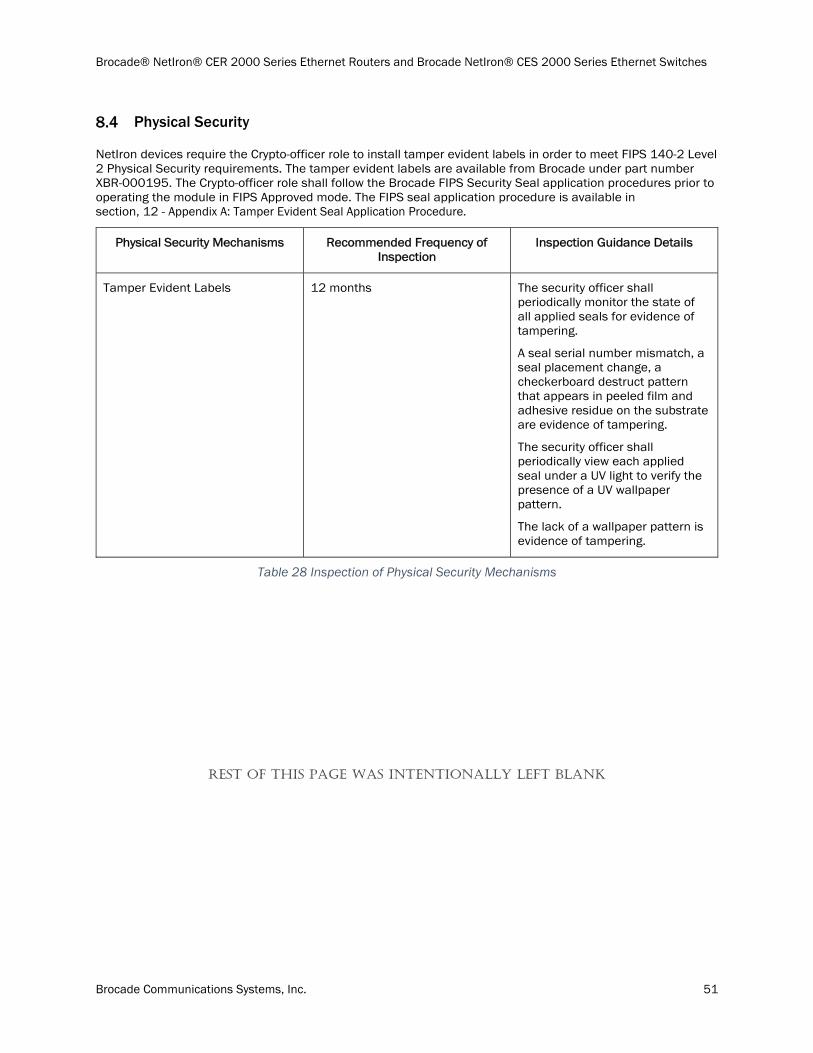
Brocade® NetIron® CER 2000 Series Ethernet Routers and Brocade NetIron® CES 2000 Series Ethernet Switches
Brocade Communications Systems, Inc. 51
Physical Security
NetIron devices require the Crypto-officer role to install tamper evident labels in order to meet FIPS 140-2 Level 2 Physical Security requirements. The tamper evident labels are available from Brocade under part number XBR-000195. The Crypto-officer role shall follow the Brocade FIPS Security Seal application procedures prior to operating the module in FIPS Approved mode. The FIPS seal application procedure is available in section, 12 - Appendix A: Tamper Evident Seal Application Procedure.
Physical Security Mechanisms Recommended Frequency of Inspection
Inspection Guidance Details
Tamper Evident Labels 12 months The security officer shall periodically monitor the state of all applied seals for evidence of tampering.
A seal serial number mismatch, a seal placement change, a checkerboard destruct pattern that appears in peeled film and adhesive residue on the substrate are evidence of tampering.
The security officer shall periodically view each applied seal under a UV light to verify the presence of a UV wallpaper pattern.
The lack of a wallpaper pattern is evidence of tampering.
Table 28 Inspection of Physical Security Mechanisms
REST OF THIS PAGE WAS INTENTIONALLY LEFT BLANK
Brocade® NetIron® CER 2000 Series Ethernet Routers and Brocade NetIron® CES 2000 Series Ethernet Switches
Brocade Communications Systems, Inc. 52
NEXT PAGE

Brocade® NetIron® CER 2000 Series Ethernet Routers and Brocade NetIron® CES 2000 Series Ethernet Switches
Brocade Communications Systems, Inc. 53
Crypto-officer Guidance
For each module to operate in a FIPS Approved mode of operation, the tamper evident seals supplied in Brocade XBR-000195 must be installed, as defined in section, 12 - Appendix A: Tamper Evident Seal Application Procedure.
The security officer is responsible for storing and controlling the inventory of any unused seals. The unused seals shall be stored in plastic bags in a cool, dry environment between 60° and 70° F (15° to 20° C) and less than 50% relative humidity. Rolls should be stored flat on a slit edge or suspended by the core.
The security officer shall maintain a serial number inventory of all used and unused tamper evident seals. The security officer is responsible for returning a module to a FIPS Approved state after any intentional or unintentional reconfiguration of the physical security measures.
FIPS Approved Mode Status
NetIron devices provide the “fips show” command to display status information about the device’s configuration. This information includes the status of administrative commands for security policy, the status of security policy enforcement, and security policy settings. The “fips enable” command changes the status of administrative commands; see also Section 9.2 FIPS Approved Mode.
The following example shows the output of the “fips show” command before an operator enters a “fips enable” command. Administrative commands for security policy are unavailable (administrative status is off) and the device is not enforcing a security policy (operational status is off).
FIPS Version: BRCD-IP-CRYPTO-VER-3.0a FIPS mode : Administrative status OFF: Operational status OFF FIPS CC mode: Administrative status OFF: Operational status OFF
Table 29 Sample output – CES/CER in non-Approved mode
The following example shows the output of the “fips show” command after an operator enters the “fips enable” command. Administrative commands for security policy are available (administrative status is on) but the device is not enforcing a security policy yet (operational status is off). The command displays the security policy settings.
REST OF THIS PAGE WAS INTENTIONALLY LEFT BLANK
NEXT PAGE
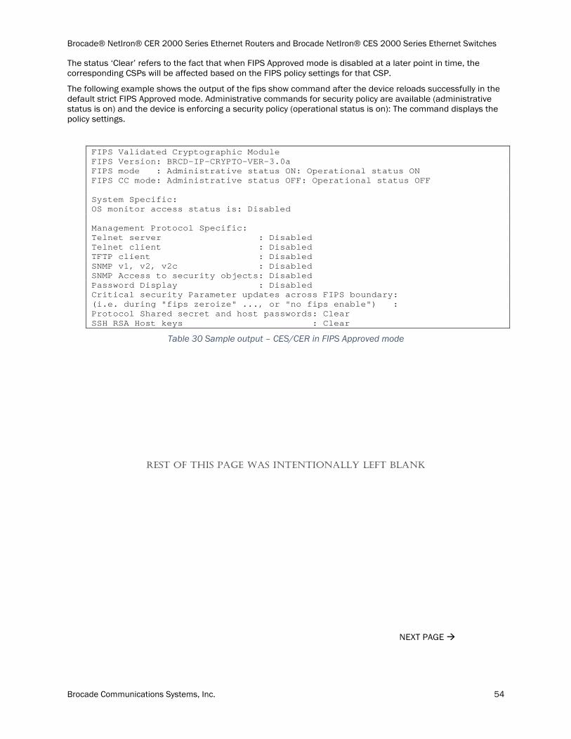
Brocade® NetIron® CER 2000 Series Ethernet Routers and Brocade NetIron® CES 2000 Series Ethernet Switches
Brocade Communications Systems, Inc. 54
The status ‘Clear’ refers to the fact that when FIPS Approved mode is disabled at a later point in time, the corresponding CSPs will be affected based on the FIPS policy settings for that CSP.
The following example shows the output of the fips show command after the device reloads successfully in the default strict FIPS Approved mode. Administrative commands for security policy are available (administrative status is on) and the device is enforcing a security policy (operational status is on): The command displays the policy settings.
FIPS Validated Cryptographic Module FIPS Version: BRCD-IP-CRYPTO-VER-3.0a FIPS mode : Administrative status ON: Operational status ON FIPS CC mode: Administrative status OFF: Operational status OFF System Specific: OS monitor access status is: Disabled Management Protocol Specific: Telnet server : Disabled Telnet client : Disabled TFTP client : Disabled SNMP v1, v2, v2c : Disabled SNMP Access to security objects: Disabled Password Display : Disabled Critical security Parameter updates across FIPS boundary: (i.e. during "fips zeroize" ..., or "no fips enable") : Protocol Shared secret and host passwords: Clear SSH RSA Host keys : Clear
Table 30 Sample output – CES/CER in FIPS Approved mode
REST OF THIS PAGE WAS INTENTIONALLY LEFT BLANK
NEXT PAGE
Brocade® NetIron® CER 2000 Series Ethernet Routers and Brocade NetIron® CES 2000 Series Ethernet Switches
Brocade Communications Systems, Inc. 55
FIPS Approved Mode
This section describes the FIPS Approved mode of operation and the sequence of actions that put a NetIron device in FIPS Approved mode. FIPS Approved mode disables the following:
1. Enter command no web-management hp-top-tools in order to turn off access by HP ProCurve Manager via port 280.
2. Telnet access including the “telnet server command”
3. AAA authentication for the console using “enable aaa console” command is temporarily disabled to allow console access to configure SSH parameters. This command can be enabled after SSH is confirmed operational
4. Command “ip ssh scp disable”
5. TFTP access
6. SNMP access to CSP MIB objects
7. Access to all commands that allows debugging memory content within the monitor mode
8. Access to the following commands get disabled:
• HTTPS SSL 3.0 access
Entering FIPS Approved mode also clears:
1. Protocol shared secret and host passwords
2. HTTPS RSA host keys and certificate
FIPS Approved mode enables:
1. SCP
2. HTTPS TLS v1.0/1.1 and TLS v1.2
Invoking FIPS Approved Mode
9.2.1.1 Invoking FIPS Approved Mode for Brocade CER 2000 series and CES 2000 series Devices
To invoke the FIPS Approved mode of operation, perform the following steps from the console terminal.
1) Assume Crypto-officer role
a) The authentication methods available for assuming the Crypto-officer role through the console terminal port are defined in Section 8.2.
2) Copy signature files of all the affected images to the flash memory.
3) Enter command: fips enable
a) The device enables FIPS administrative commands. The device is not in FIPS Approved Mode of operation yet. Do not change the default strict FIPS security policy, which is required for FIPS Approved mode.
4) Enter command: fips zeroize all
a) The device zeroizes the shared secrets used by various networking protocols including host access passwords, and SSHv2 Host keys with the digital signature.
5) Once the module completes zeroization, configure all users of the module and authentication methods as per Section 8.2.
6) Enter command: "enable strict-password-enforcement”
Brocade® NetIron® CER 2000 Series Ethernet Routers and Brocade NetIron® CES 2000 Series Ethernet Switches
Brocade Communications Systems, Inc. 56
7) Enter command: write memory
a) The device saves the running configuration as the startup configuration
8) Enter command: reload
a) The device reboots, does a Power-On Self-Test and if successful, begins operation in FIPS Approved mode.
9) Enter command: fips show
a) The device displays the FIPS-related status, which should confirm the security policy is the default security policy.
10) Inspect the physical security of the module, including placement of tamper evident labels according to section, 12 - Appendix A: Tamper Evident Seal Application Procedure.
Negating FIPS Approved Mode
9.2.2.1 Negating FIPS Approved Mode for Brocade CER 2000 Series and CES 2000 Series Devices
To exit the FIPS Approved mode of operation, perform the following steps from the console terminal.
1) Enter command: no fips enable
a) This will return the device back to normal, non-Approved mode by enabling the networking protocols that were disallowed in FIPS Approved mode of operation. For example, Telnet, TFTP will be enabled again. In addition, the restrictions against the non-Approved cryptographic algorithms will also be lifted. For example, MD5, DES algorithms would be allowed.
b) The device zeroizes the shared secrets used by various networking protocols including host access passwords, SSHv2 client and server keys, and TLS client keys with the digital signature.
2) Once the module completes zeroization, configure all users of the module and authentication methods as per Section 8.2.
3) Enter command: write memory
a) The device saves the running configuration as the startup configuration
4) Enter command: reload
a) Reload the device to begin non-Approved mode of operation.
Mitigation of other attacks
These modules have not been designed to mitigate any specific attacks beyond the scope of FIPS 140-2 requirements.
Other Attacks Mitigation mechanism Specific Limitations
N/A N/A N/A
Table 31 Mitigation of other attacks
NEXT PAGE
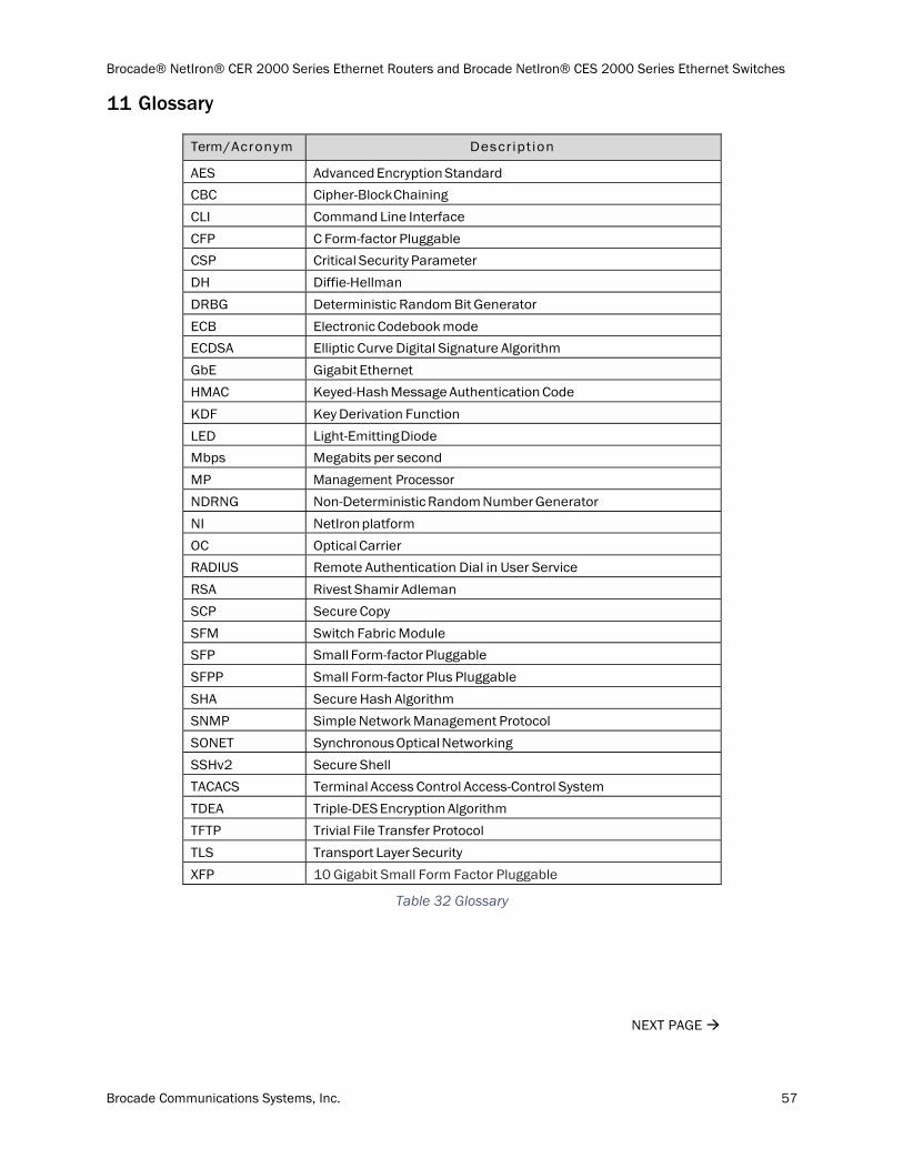
Brocade® NetIron® CER 2000 Series Ethernet Routers and Brocade NetIron® CES 2000 Series Ethernet Switches
Brocade Communications Systems, Inc. 57
Glossary
Term / Acronym Descript ion
AES Advanced Encryption Standard
CBC Cipher-Block Chaining
CLI Command Line Interface
CFP C Form-factor Pluggable
CSP Critical Security Parameter
DH Diffie-Hellman
DRBG Deterministic Random Bit Generator
ECB Electronic Codebook mode
ECDSA Elliptic Curve Digital Signature Algorithm
GbE Gigabit Ethernet
HMAC Keyed-Hash Message Authentication Code
KDF Key Derivation Function
LED Light-Emitting Diode
Mbps Megabits per second
MP Management Processor
NDRNG Non-Deterministic Random Number Generator
NI NetIron platform
OC Optical Carrier
RADIUS Remote Authentication Dial in User Service
RSA Rivest Shamir Adleman
SCP Secure Copy
SFM Switch Fabric Module
SFP Small Form-factor Pluggable
SFPP Small Form-factor Plus Pluggable
SHA Secure Hash Algorithm
SNMP Simple Network Management Protocol
SONET Synchronous Optical Networking
SSHv2 Secure Shell
TACACS Terminal Access Control Access-Control System
TDEA Triple-DES Encryption Algorithm
TFTP Trivial File Transfer Protocol
TLS Transport Layer Security
XFP 10 Gigabit Small Form Factor Pluggable
Table 32 Glossary
NEXT PAGE

Brocade® NetIron® CER 2000 Series Ethernet Routers and Brocade NetIron® CES 2000 Series Ethernet Switches
Brocade Communications Systems, Inc. 58
Appendix A: Tamper Evident Seal Application Procedure
The FIPS Kit (SKU XBR-000195) contains the following items:
Tamper Evident Security Seals
o Count 120
o Checkerboard destruct pattern with ultraviolet visible “Secure” image
Use 99% isopropyl alcohols to clean the surface area at each tamper evident seal placement location. Isopropyl alcohol is not provided in the kit. However, 99% isopropyl alcohol is readily available for purchase from a chemical supply company. Prior to applying a new seal to an area, that shows seal residue, use consumer strength adhesive remover to remove the seal residue. Then use additional alcohol to clean off any residual adhesive remover before applying a new seal.
Brocade CER 2000 series
CER 2024C-4X-RT devices
Use the figures in this section as a guide for security seal placement on a Brocade NetIron CER 2024C-4X-RT. Brocade NetIron CER 2024C-4X-RT device require the placement of eighteen (18) seals:
Top front: Affix one (1) seal over each flat head that connects the top cover to the base of the chassis. Five (5) seals are needed to complete this step of the procedure (Seals 1 through 5). One (1) seal is placed vertically over the console port (Seal 18). See Figure 18 for correct seal orientation and positioning.
Right and left sides: Affix three (3) seals on the left and right sides of the device. The seals must be vertically oriented, cover the flathead screws that attach the top cover to the base of the chassis and wrap around to the bottom of the chassis. Six (6) seals are needed to complete this step of the procedure (Seals 6 through 11). The orientation and placement of seals on the left and right sides mirrors each other. See Figure 19 and Figure 20 for correct seal orientation.
Rear: Affix six (6) seals across the back of the chassis to inhibit the removal of a power supply, power supply filler panel or fan module. Seal 13 wraps from the top cover to the filler panel. Seals 15 and 16 wrap from the top cover to the fan module. See Figure 21 for correct seal placement. Seal 12 touches both the power supply module and filler panel before wrapping onto the bottom of the chassis. Seals 14 and 17 wrap from the fan module to the bottom of the chassis. See Figure 21 and Figure 22 for correct seal placement.
REST OF THIS PAGE WAS INTENTIONALLY LEFT BLANK
NEXT PAGE
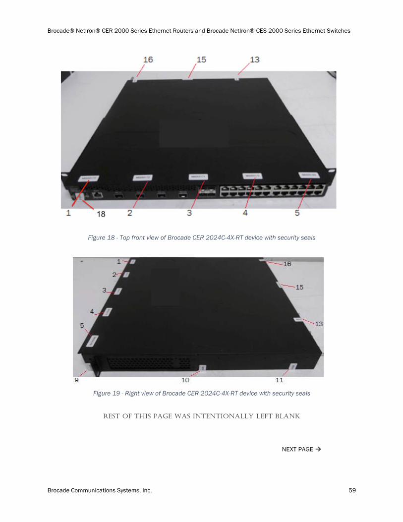
Brocade® NetIron® CER 2000 Series Ethernet Routers and Brocade NetIron® CES 2000 Series Ethernet Switches
Brocade Communications Systems, Inc. 59
Figure 18 - Top front view of Brocade CER 2024C-4X-RT device with security seals
Figure 19 - Right view of Brocade CER 2024C-4X-RT device with security seals
REST OF THIS PAGE WAS INTENTIONALLY LEFT BLANK
NEXT PAGE
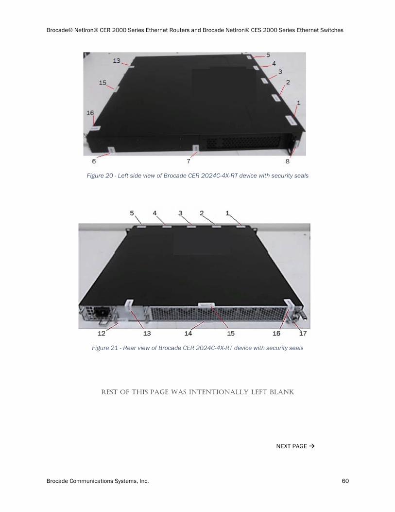
Brocade® NetIron® CER 2000 Series Ethernet Routers and Brocade NetIron® CES 2000 Series Ethernet Switches
Brocade Communications Systems, Inc. 60
Figure 20 - Left side view of Brocade CER 2024C-4X-RT device with security seals
Figure 21 - Rear view of Brocade CER 2024C-4X-RT device with security seals
REST OF THIS PAGE WAS INTENTIONALLY LEFT BLANK
NEXT PAGE
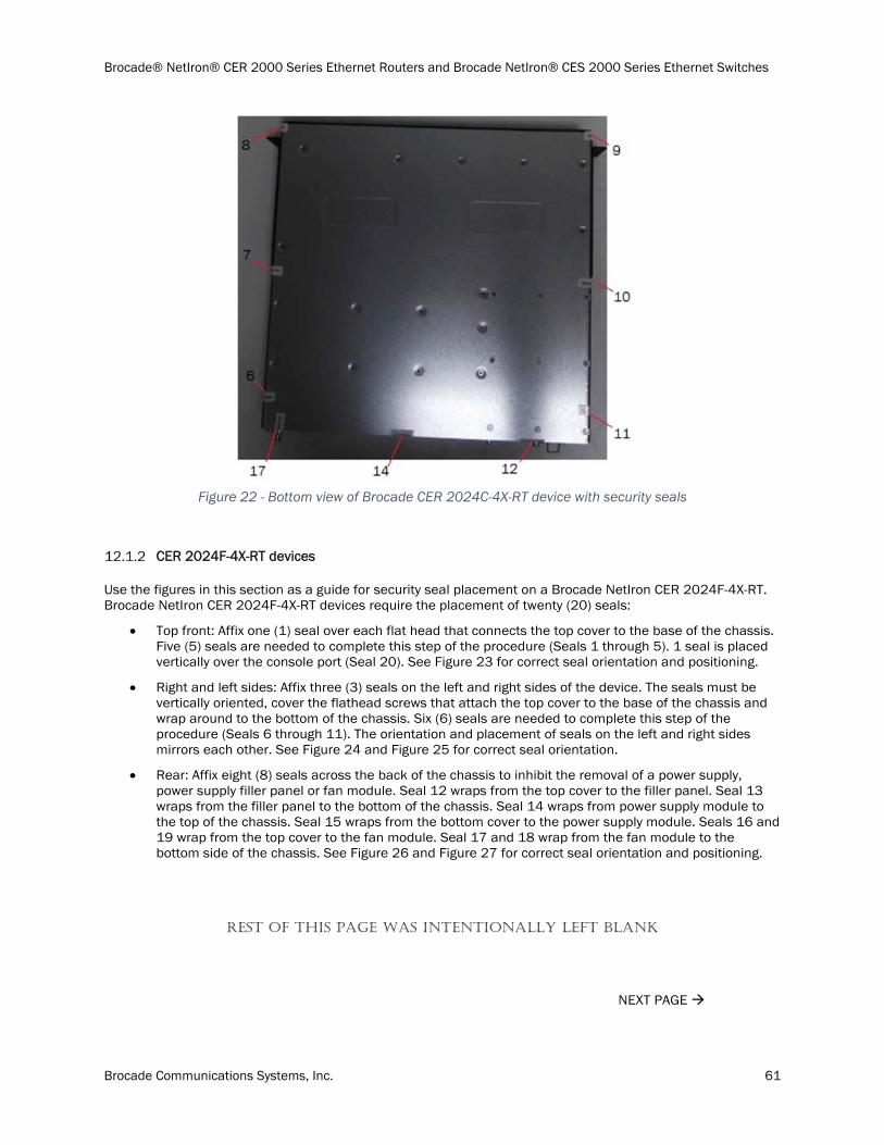
Brocade® NetIron® CER 2000 Series Ethernet Routers and Brocade NetIron® CES 2000 Series Ethernet Switches
Brocade Communications Systems, Inc. 61
Figure 22 - Bottom view of Brocade CER 2024C-4X-RT device with security seals
CER 2024F-4X-RT devices
Use the figures in this section as a guide for security seal placement on a Brocade NetIron CER 2024F-4X-RT. Brocade NetIron CER 2024F-4X-RT devices require the placement of twenty (20) seals:
Top front: Affix one (1) seal over each flat head that connects the top cover to the base of the chassis. Five (5) seals are needed to complete this step of the procedure (Seals 1 through 5). 1 seal is placed vertically over the console port (Seal 20). See Figure 23 for correct seal orientation and positioning.
Right and left sides: Affix three (3) seals on the left and right sides of the device. The seals must be vertically oriented, cover the flathead screws that attach the top cover to the base of the chassis and wrap around to the bottom of the chassis. Six (6) seals are needed to complete this step of the procedure (Seals 6 through 11). The orientation and placement of seals on the left and right sides mirrors each other. See Figure 24 and Figure 25 for correct seal orientation.
Rear: Affix eight (8) seals across the back of the chassis to inhibit the removal of a power supply, power supply filler panel or fan module. Seal 12 wraps from the top cover to the filler panel. Seal 13 wraps from the filler panel to the bottom of the chassis. Seal 14 wraps from power supply module to the top of the chassis. Seal 15 wraps from the bottom cover to the power supply module. Seals 16 and 19 wrap from the top cover to the fan module. Seal 17 and 18 wrap from the fan module to the bottom side of the chassis. See Figure 26 and Figure 27 for correct seal orientation and positioning.
REST OF THIS PAGE WAS INTENTIONALLY LEFT BLANK
NEXT PAGE
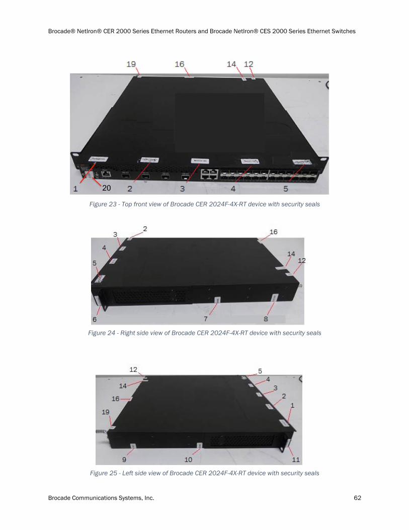
Brocade® NetIron® CER 2000 Series Ethernet Routers and Brocade NetIron® CES 2000 Series Ethernet Switches
Brocade Communications Systems, Inc. 62
Figure 23 - Top front view of Brocade CER 2024F-4X-RT device with security seals
Figure 24 - Right side view of Brocade CER 2024F-4X-RT device with security seals
Figure 25 - Left side view of Brocade CER 2024F-4X-RT device with security seals
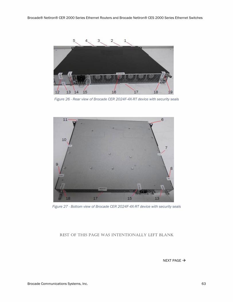
Brocade® NetIron® CER 2000 Series Ethernet Routers and Brocade NetIron® CES 2000 Series Ethernet Switches
Brocade Communications Systems, Inc. 63
Figure 26 - Rear view of Brocade CER 2024F-4X-RT device with security seals
Figure 27 - Bottom view of Brocade CER 2024F-4X-RT device with security seals
REST OF THIS PAGE WAS INTENTIONALLY LEFT BLANK
NEXT PAGE
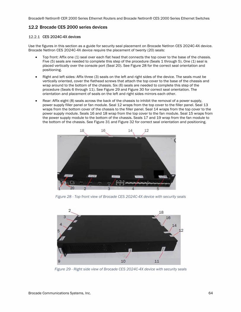
Brocade® NetIron® CER 2000 Series Ethernet Routers and Brocade NetIron® CES 2000 Series Ethernet Switches
Brocade Communications Systems, Inc. 64
Brocade CES 2000 series devices
CES 2024C-4X devices
Use the figures in this section as a guide for security seal placement on Brocade NetIron CES 2024C-4X device. Brocade NetIron CES 2024C-4X device require the placement of twenty (20) seals:
Top front: Affix one (1) seal over each flat head that connects the top cover to the base of the chassis. Five (5) seals are needed to complete this step of the procedure (Seals 1 through 5). One (1) seal is placed vertically over the console port (Seal 20). See Figure 28 for the correct seal orientation and positioning.
Right and left sides: Affix three (3) seals on the left and right sides of the device. The seals must be vertically oriented, cover the flathead screws that attach the top cover to the base of the chassis and wrap around to the bottom of the chassis. Six (6) seals are needed to complete this step of the procedure (Seals 6 through 11). See Figure 29 and Figure 30 for correct seal orientation. The orientation and placement of seals on the left and right sides mirrors each other.
Rear: Affix eight (8) seals across the back of the chassis to inhibit the removal of a power supply, power supply filler panel or fan module. Seal 12 wraps from the top cover to the filler panel. Seal 13 wraps from the bottom cover of the chassis to the filler panel. Seal 14 wraps from the top cover to the power supply module. Seals 16 and 18 wrap from the top cover to the fan module. Seal 15 wraps from the power supply module to the bottom of the chassis. Seals 17 and 19 wrap from the fan module to the bottom of the chassis. See Figure 31 and Figure 32 for correct seal orientation and positioning.
Figure 28 - Top front view of Brocade CES 2024C-4X device with security seals
Figure 29 - Right side view of Brocade CES 2024C-4X device with security seals
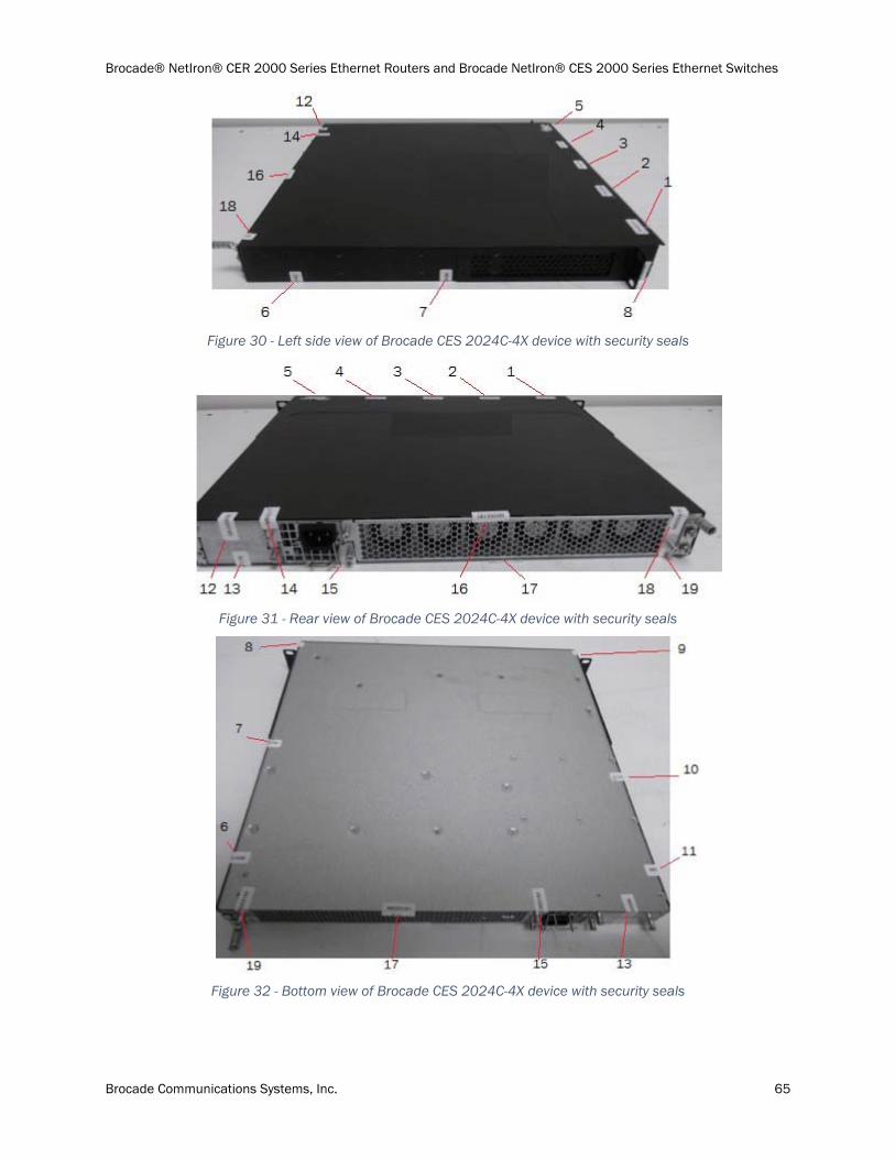
Brocade® NetIron® CER 2000 Series Ethernet Routers and Brocade NetIron® CES 2000 Series Ethernet Switches
Brocade Communications Systems, Inc. 65
Figure 30 - Left side view of Brocade CES 2024C-4X device with security seals
Figure 31 - Rear view of Brocade CES 2024C-4X device with security seals
Figure 32 - Bottom view of Brocade CES 2024C-4X device with security seals
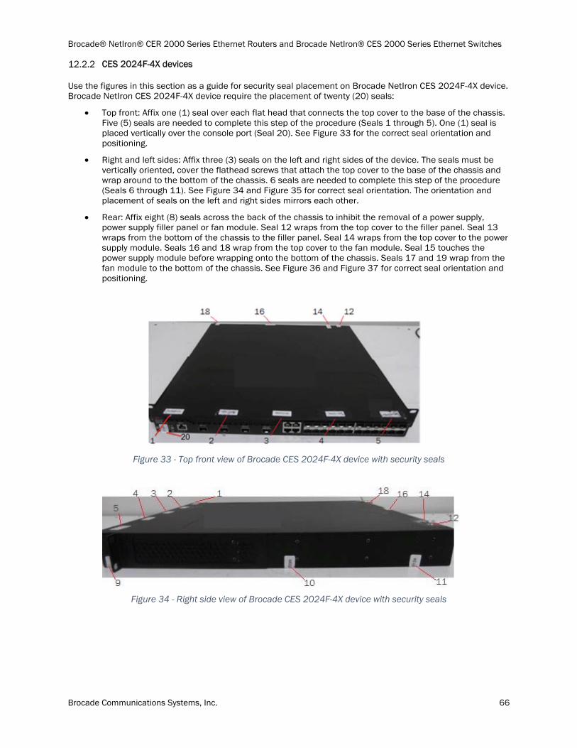
Brocade® NetIron® CER 2000 Series Ethernet Routers and Brocade NetIron® CES 2000 Series Ethernet Switches
Brocade Communications Systems, Inc. 66
CES 2024F-4X devices
Use the figures in this section as a guide for security seal placement on Brocade NetIron CES 2024F-4X device. Brocade NetIron CES 2024F-4X device require the placement of twenty (20) seals:
Top front: Affix one (1) seal over each flat head that connects the top cover to the base of the chassis. Five (5) seals are needed to complete this step of the procedure (Seals 1 through 5). One (1) seal is placed vertically over the console port (Seal 20). See Figure 33 for the correct seal orientation and positioning.
Right and left sides: Affix three (3) seals on the left and right sides of the device. The seals must be vertically oriented, cover the flathead screws that attach the top cover to the base of the chassis and wrap around to the bottom of the chassis. 6 seals are needed to complete this step of the procedure (Seals 6 through 11). See Figure 34 and Figure 35 for correct seal orientation. The orientation and placement of seals on the left and right sides mirrors each other.
Rear: Affix eight (8) seals across the back of the chassis to inhibit the removal of a power supply, power supply filler panel or fan module. Seal 12 wraps from the top cover to the filler panel. Seal 13 wraps from the bottom of the chassis to the filler panel. Seal 14 wraps from the top cover to the power supply module. Seals 16 and 18 wrap from the top cover to the fan module. Seal 15 touches the power supply module before wrapping onto the bottom of the chassis. Seals 17 and 19 wrap from the fan module to the bottom of the chassis. See Figure 36 and Figure 37 for correct seal orientation and positioning.
Figure 33 - Top front view of Brocade CES 2024F-4X device with security seals
Figure 34 - Right side view of Brocade CES 2024F-4X device with security seals
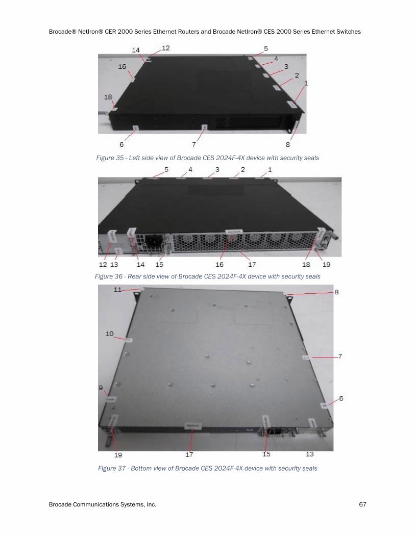
Brocade® NetIron® CER 2000 Series Ethernet Routers and Brocade NetIron® CES 2000 Series Ethernet Switches
Brocade Communications Systems, Inc. 67
Figure 35 - Left side view of Brocade CES 2024F-4X device with security seals
Figure 36 - Rear side view of Brocade CES 2024F-4X device with security seals
Figure 37 - Bottom view of Brocade CES 2024F-4X device with security seals
Brocade® NetIron® CER 2000 Series Ethernet Routers and Brocade NetIron® CES 2000 Series Ethernet Switches
Brocade Communications Systems, Inc. 68
Appendix B: Critical Security Parameters
The module supports the following CSPs and public keys:
Authentication Key
1) Local - Crypto-officer Password
- Description: Locally configured password used to authenticate operators (8 to 48 characters)
- Type: Authentication data
- Generation: N/A
- Establishment: N/A
- Entry: Entered AES encrypted & HMAC-SHA-1 authenticated over SSHv2 session
- Output: Output AES encrypted & HMAC-SHA-1 authenticated over SSHv2 session
- Storage: Plaintext in Compact Flash
- Key-to-Entity: user
- Zeroization: "fips zeroize all" command
2) Local - Port Administrator Password
- Description: Locally configured password used to authenticate operators (8 to 48 characters)
- Type: Authentication data
- Generation: N/A
- Establishment: N/A
- Entry: Entered AES encrypted & HMAC-SHA-1 authenticated over SSHv2 session
- Output: Output AES encrypted & HMAC-SHA-1 authenticated over SSHv2 session
- Storage: Plaintext in Compact Flash
- Key-to-Entity: user
- Zeroization: "fips zeroize all" command
3) Local - User Password
- Description: Locally configured password used to authenticate operators (8 to 48 characters)
- Type: Authentication data
- Generation: N/A
- Establishment: N/A
- Entry: Entered AES encrypted & HMAC-SHA-1 authenticated over SSHv2 session
- Output: Output AES encrypted & HMAC-SHA-1 authenticated over SSHv2 session
- Storage: Plaintext in Compact Flash
- Key-to-Entity: user
- Zeroization: "fips zeroize all" command
Brocade® NetIron® CER 2000 Series Ethernet Routers and Brocade NetIron® CES 2000 Series Ethernet Switches
Brocade Communications Systems, Inc. 69
4) SSHv2/SCP Authentication Key (HMAC-SHA-1, 160 bits)
- Description: Session authentication key used to authenticate and provide integrity of SSHv2 session
- Type: HMAC-SHA-1
- Generation: N/A
- Establishment: SSHv2 DH Key Agreement and SSHv2 KDF (SP800-135 Section 5.2); allowed method as per FIPS 140-2 IG D.8 Scenario 4
- Entry: N/A
- Output: N/A
- Storage: Plaintext in RAM
- Key-to-Entity: User
- Zeroization: Session termination and "fips zeroize all" command
5) TLS Authentication Key
- Description: HMAC-SHA-1 key (20 bytes) used to provide data authentication for TLS v1.0/1.1 sessions; HMAC-SHA-256 key (32 bytes) used to provide data authentication for TLS v1.2 sessions
- Type: TLS v1.0/1.1 (HMAC-SHA-1); TLS v1.2 (HMAC-SHA-256)
- Generation: N/A
- Establishment: TLS v1.0/1.1 and TLS v1.2 KDF as per SP800-135 Section 4.2.1 & 4.2.2; allowed method as per FIPS 140-2 IG D.8 Scenario 4
- Entry: N/A
- Output: N/A
- Storage: Plaintext in RAM
- Key-to-Entity: user
- Zeroization: Session termination and "fips zeroize all" command
KDF
6) SSHv2 KDF Internal State
- Description: Used to generate Host encryption and authentication key on MP
- Type: SHA-256
- Generation: N/A
- Establishment: SSHv2 DH Key Agreement and SSHv2 KDF (SP800-135 Section 5.2); allowed method as per FIPS 140-2 IG D.8 Scenario 4
- Entry: N/A
- Output: N/A
- Storage: Plaintext in RAM
- Key-to-Entity: user
- Zeroization: Session termination and "fips zeroize all" command

Brocade® NetIron® CER 2000 Series Ethernet Routers and Brocade NetIron® CES 2000 Series Ethernet Switches
Brocade Communications Systems, Inc. 70
7) TLS KDF Internal State
- Description: Values of the KDF internal state on MP
- Type: TLS v1.0/1.1 (HMAC-SHA-1/HMAC-MD5); TLS v1.2 (HMAC-SHA-256)
- Generation: N/A
- Establishment: TLS v1.0/1.1 and TLS v1.2 KDF as per SP800-135 Section 4.2.1 & 4.2.2; allowed method as per FIPS 140-2 IG D.8 Scenario 4
- Entry: N/A
- Output: N/A
- Storage: Plaintext in RAM
- Key-to-Entity: user
- Zeroization: Session termination and "fips zeroize all" command
8) SNMPv3 KDF State
- Description: SHA-1 Key Localization Function
- Generation: N/A
- Establishment: SNMPv3 KDF (SP800-135 Section 5.4); allowed method as per FIPS 140-2 IG D.8 Scenario 4
- Entry: N/A
- Output: N/A
- Storage: Plaintext in RAM
- Key-To-Entity: User
- Zeroization: Session termination and "fips zeroize all" command
Management card (MP) DRBG
9) MP DRBG Internal State
- Description: Internal State of SP800-90A CTR_DRBG
- Type: SP800-90A DRBG
- Generation: SP800-90A DRBG
- Establishment: N/A
- Entry: N/A
- Output: N/A
- Storage: Plaintext in RAM
- Key-to-Entity: Process
- Zeroization: "fips zeroize all" command

Brocade® NetIron® CER 2000 Series Ethernet Routers and Brocade NetIron® CES 2000 Series Ethernet Switches
Brocade Communications Systems, Inc. 71
10) MP DRBG Seed
- Description: Seeding material for the SP800-90A CTR_DRBG
- Type: DRBG Seed material
- Generation: Internally generated using the NDRNG
- Establishment: N/A
- Entry: N/A
- Output: N/A
- Storage: Plaintext in RAM
- Key-to-Entity: Process
- Zeroization: "fips zeroize all" command
11) MP DRBG Value V
- Description: Internal State of SP800-90A CTR_DRBG: 128 bits
- Type: SP800-90A DRBG
- Generation: SP800-90A DRBG
- Establishment: N/A
- Entry: N/A
- Output: N/A
- Storage: Plaintext in RAM
- Key-to-Entity: Process
- Zeroization: "fips zeroize all" command
12) MP DRBG Key
- Description: Internal State of SP800-90A CTR_DRBG: 256 bits
- Type: SP800-90A DRBG
- Generation: SP800-90A DRBG
- Establishment: N/A
- Entry: N/A
- Output: N/A
- Storage: Plaintext in RAM
- Key-to-Entity: Process
- Zeroization: "fips zeroize all" command
Brocade® NetIron® CER 2000 Series Ethernet Routers and Brocade NetIron® CES 2000 Series Ethernet Switches
Brocade Communications Systems, Inc. 72
Private Keys
*** SSHv2 ***
13) SSHv2 Client RSA Private Key
- Description: (2048 bit); Used to establish shared secrets (SSHv2)
- Type: RSA Private Key
- Generation: As per SP800-133 Section 6.1, key generation is performed as per FIPS 186-4 which is an Approved key generation method
- Establishment: N/A
- Entry: N/A
- Output: N/A
- Storage: Plaintext in RAM, Plaintext in Compact Flash
- Key-to-Entity: Process
- Zeroization: "fips zeroize all" command
14) SSHv2 DH Group-14 Private Key 2048 bit MODP
- Description: Used in SCP and SSHv2 to establish a shared secret
- Type: DH Private Key
- Generation: As per SP800-133 Section 6.2, the random value (K) needed to generate key pairs for the finite field is the output of the SP800-90A DRBG; this is Approved as per SP800-56A
- Establishment: N/A
- Entry: N/A
- Output: N/A
- Storage: Plaintext in RAM
- Key-to-Entity: Process
- Zeroization: Session termination and "fips zeroize all" command
15) SSHv2 Host RSA Private Key (2048 bit)
- Description: Used to authenticate SSHv2 server to client
- Type: RSA Private Key
- Generation: As per SP800-133 Section 6.1, key generation is performed as per FIPS 186-4 which is an Approved key generation method
- Establishment: N/A
- Entry: N/A
- Output: N/A
- Storage: Plaintext in RAM and BER encoded (plaintext) in Compact Flash
- Key-to-Entity: Process
- Zeroization: "fips zeroize all" command
Brocade® NetIron® CER 2000 Series Ethernet Routers and Brocade NetIron® CES 2000 Series Ethernet Switches
Brocade Communications Systems, Inc. 73
*** TLS ***
16) TLS Host RSA Private Key (RSA 2048 bit)
- Description: RSA key used to establish TLS v1.0/1.1 and TLS v1.2 sessions
- Type: RSA Private Key
- Generation: N/A
- Establishment: Key transport: AES Encrypted & HMAC-SHA-1 authenticated over SSHv2 session; Approved as per FIPS 140-2 IG D.9
- Entry: AES Encrypted and HMAC-SHA-1 authenticated over SSHv2 session
- Output: N/A
- Storage: Plaintext in RAM and DER encoded (plaintext) in Compact Flash
- Key-to-Entity: Process
- Zeroization: "fips zeroize all" command
17) TLS Host DH Group-14 Private Key 2048 bit MODP
- Description: Used in TLS to establish a Pre-Master secret
- Type: DH Private Key
- Generation: As per SP800-133 Section 6.2, the random value (K) needed to generate key pairs for the finite field is the output of the SP800-90A DRBG; this is Approved as per SP800-56A
- Establishment: N/A
- Entry: N/A
- Output: N/A
- Storage: Plaintext in RAM
- Key-to-Entity: Process
- Zeroization: Session termination and "fips zeroize all" command
Public Keys
*** SSHv2 ***
18) SSHv2 Client RSA Public Key
- Description: (2048 bit); Used to establish shared secrets (SSHv2)
- Type: RSA Public Key
- Generation: As per SP800-133 Section 6.1, key generation is performed as per FIPS 186-4 which is an Approved key generation method
- Establishment: N/A
- Entry: N/A
- Output: Plaintext
- Storage: Plaintext in RAM, Plaintext in Compact Flash
- Key-to-Entity: Process
Brocade® NetIron® CER 2000 Series Ethernet Routers and Brocade NetIron® CES 2000 Series Ethernet Switches
Brocade Communications Systems, Inc. 74
19) SSHv2 DH Group-14 Peer Public Key 2048 bit MODP
- Description: Used in SCP and SSHv2 to establish a shared secret
- Type: DH Peer Public Key
- Generation: N/A
- Establishment: N/A
- Entry: Plaintext
- Output: N/A
- Storage: Plaintext in RAM
- Key-to-Entity: Process
20) SSHv2 DH Group-14 Public Key 2048 bit MODP
- Description: Used in SCP and SSHv2 to establish a shared secret
- Type: DH Public Key
- Generation: As per SP800-133 Section 6.2, the random value (K) needed to generate key pairs for the finite field is the output of the SP800-90A DRBG; this is Approved as per SP800-56A
- Establishment: N/A
- Entry: N/A
- Output: Plaintext
- Storage: Plaintext in RAM, Plaintext in Compact Flash
- Key-to-Entity: Process
21) SSHv2 Host RSA Public Key (2048 bit)
- Description: Used to establish shared secrets (SSHv2)
- Type: RSA Public Key
- Generation: As per SP800-133 Section 6.1, key generation is performed as per FIPS 186-4 which is an Approved key generation method
- Establishment: N/A
- Entry: N/A
- Output: Plaintext
- Storage: Plaintext in RAM and BER encoded (plaintext) in Compact Flash
- Key-to-Entity: Process
Brocade® NetIron® CER 2000 Series Ethernet Routers and Brocade NetIron® CES 2000 Series Ethernet Switches
Brocade Communications Systems, Inc. 75
*** TLS ***
22) TLS Host RSA Public Key (RSA 2048 bit)
- Description: Presented to peer during TLS Handshake.
- Type: TLS host Public key
- Generation: N/A
- Establishment: Key transport: AES Encrypted & HMAC-SHA-1 authenticated over SSHv2 session; Approved as per FIPS 140-2 IG D.9
- Entry: AES Encrypted and HMAC-SHA-1 authenticated over SSHv2 session
- Output: Plaintext
- Storage: Plaintext in RAM, Plaintext in Compact Flash
- Key-to-Entity: Process
23) TLS Peer Public Key (RSA 2048 bit)
- Description: Used to authenticate the peer
- Type: TLS Peer Public Key
- Generation: N/A
- Establishment: N/A
- Entry: Plaintext during TLS v1.0/1.1 and TLS v1.2 handshake protocol
- Output: N/A
- Storage: Plaintext in RAM
- Key-to-Entity: Process
24) TLS Host DH Group-14 Public Key 2048 bit MODP
- Description: Used by peer for establishment of the TLS pre-master secret.
- Type: DH Public Key
- Generation: As per SP800-133 Section 6.2, the random value (K) needed to generate key pairs for the finite field is the output of the SP800-90A DRBG; this is Approved as per SP800-56A
- Establishment: N/A
- Entry: N/A
- Output: Plaintext during TLS v1.0/1.1 and TLS v1.2 handshake protocol
- Storage: Plaintext in RAM
- Key-to-Entity: Process
Brocade® NetIron® CER 2000 Series Ethernet Routers and Brocade NetIron® CES 2000 Series Ethernet Switches
Brocade Communications Systems, Inc. 76
25) TLS Peer DH Group-14 Public Key 2048 bit MODP
- Description: Used in TLS to establish a TLS Pre-Master Secret
- Type: DH Public Key
- Generation: N/A
- Establishment: N/A
- Entry: Plaintext during TLS v1.0/1.1 and TLS v1.2 handshake protocol
- Output: N/A
- Storage: Plaintext in RAM
- Key-to-Entity: Process
*** Firmware ***
26) Firmware Load RSA Public Key
- Description: RSA 2048-bit public key used to verify signature of firmware of the module
- Type: RSA Public Key
- Generation: N/A, Generated outside the module
- Establishment: N/A
- Entry: Through firmware update
- Output: N/A
- Storage: Plaintext in RAM, Plaintext in Compact Flash
- Key-to-Entity: Process
Session Keys
*** SSHv2 ***
27) SSHv2/SCP Session Keys (128, 192 and 256 bit AES CBC and AES CTR)
- Description: AES encryption key used to secure SSHv2/SCP on MP
- Type: AES CBC Key
- Generation: N/A
- Establishment: SSHv2 DH Key Agreement and SSHv2 KDF (SP800-135 Section 5.2); allowed method as per FIPS 140-2 IG D.8 Scenario 4
- Entry: N/A
- Output: N/A
- Storage: Plaintext in RAM
-Key-to-Entity: user
- Zeroization: Session termination and "fips zeroize all" command
Brocade® NetIron® CER 2000 Series Ethernet Routers and Brocade NetIron® CES 2000 Series Ethernet Switches
Brocade Communications Systems, Inc. 77
*** TLS ***
28) TLS Session Key
- Description: 128 or 256 bit AES CBC key used to secure TLS v1.0/1.1 and TLS v1.2 sessions on MP
- Type: AES CBC
- Generation: N/A
- Establishment: TLS v1.0/1.1 KDF and TLS v1.2 KDF as per SP800-135 Section 4.2.1 & 4.2.2; allowed method as per FIPS 140-2 IG D.8 Scenario 4
- Entry: N/A
- Output: N/A
- Storage: Plaintext in RAM
- Key-to-Entity: user
- Zeroization: Session termination and "fips zeroize all" command
Shared Secret
*** RADIUS ***
29) RADIUS Secret
- Description: Used to authenticate the RADIUS server (8 to 64 characters) on MP
- Type: Authentication data
- Generation: N/A
- Establishment: N/A
- Entry: Entered AES encrypted & HMAC-SHA-1 authenticated over SSHv2 session
- Output: Output AES encrypted & HMAC-SHA-1 authenticated over SSHv2 session
- Storage: Plaintext in RAM and Compact Flash
- Key-to-Entity: Process
- Zeroization: "fips zeroize all" command
*** SNMPv3 ***
30) SNMPv3 secret
- Description: Used for authentication (SHA1, Password is 8 to 20 characters long) and for privacy (AES, Password 12 to 16 characters)
- Type: Authentication data and privacy
- Generation: N/A - generated outside of the module
- Establishment: N/A
- Entry: Configured by the operator, entered encrypted/authenticated over SSHv2 session
- Output: SHA1 hashed in configuration, output encrypted / authenticated over SSHv2 session
- Storage: SHA1 digest and AES are stored in Compact Flash
- Key-to-Entity: Process: user
- Zeroization: Session termination and "fips zeroize all" command
Brocade® NetIron® CER 2000 Series Ethernet Routers and Brocade NetIron® CES 2000 Series Ethernet Switches
Brocade Communications Systems, Inc. 78
31) NTP secret
- Description: Authentication (SHA1, Password is 8 to 16 characters long)
- Type: Authentication data
- Generation: N/A - generated outside of the module
- Establishment: N/A
- Entry: Entered AES encrypted & HMAC-SHA-1 authenticated over SSHv2 session
- Output: Entered AES encrypted & HMAC-SHA-1 authenticated over SSHv2 session
- Storage: Plaintext in RAM and Compact Flash
- Key-to-Entity: Process: user
- Zeroization: Session termination and "fips zeroize all" command
*** SSHv2 ***
32) SSHv2 DH Shared Secret Key (2048 bit)
- Description: Output from the DH Key agreement primitive - (K) and (H). This key is used by SSHv2 KDF to derive (client and server) session keys on MP.
- Type: DH Shared Secret Key
- Generation: N/A
- Establishment: SSHv2 DH Key Agreement; allowed method as per FIPS 140-2 IG D.8 Scenario 4.
- Entry: N/A
- Output: N/A
- Storage: Plaintext in RAM
- Key-to-Entity: user
- Zeroization: Session termination and "fips zeroize all" command
*** TACACS+ ***
33) TACACS+ Secret
- Description: Used to authenticate the TACACS+ packets from the server on MP. Shared secret size is between 8 to 64 characters long
- Type: Authentication data
- Generation: N/A
- Establishment: N/A
- Entry: Entered AES encrypted & HMAC-SHA-1 authenticated over SSHv2 session
- Output: Output AES encrypted & HMAC-SHA-1 authenticated over SSHv2 session
- Storage: Plaintext in RAM and Compact Flash
- Key-to-Entity: Process
- Zeroization: "fips zeroize all" command

Brocade® NetIron® CER 2000 Series Ethernet Routers and Brocade NetIron® CES 2000 Series Ethernet Switches
Brocade Communications Systems, Inc. 79
*** TLS ***
34) TLS Master Secret
- Description: 48 bytes secret value used to establish the TLS Session Key and TLS Authentication Key on MP
- Type: TLS v1.0/1.1 and TLS v1.2 CSP
- Generation: N/A
- Establishment: TLS v1.0/1.1 and TLS v1.2 KDF as per SP800-135 Section 4.2.1 & 4.2.2; allowed method as per FIPS 140-2 IG D.8 Scenario 4
- Entry: N/A
- Output: N/A
- Storage: Plaintext in RAM
- Key-to-Entity: user
- Zeroization: Session termination and "fips zeroize all" command
35) TLS Pre-Master Secret
- Description: Secret value used to establish the Session and Authentication key on MP
- Type: 48 bytes TLS v1.0/1.1 and TLS v1.2 CSP
- Generation: Generated when the module behaves as a TLS Client when using RSA key transport
- Establishment: Key agreement: TLS DH Key Agreement: allowed method as per FIPS 140-2 IG D.8 Scenario 4
- Entry: N/A
- Output: RSA key wrapped over TLS v1.0/1.1 and TLS v1.2 session when using RSA key transport
- Storage: Plaintext in RAM
- Key-to-Entity: user
- Zeroization: Session termination and "fips zeroize all" command
REST OF THIS PAGE WAS INTENTIONALLY LEFT BLANK
NEXT PAGE
Brocade® NetIron® CER 2000 Series Ethernet Routers and Brocade NetIron® CES 2000 Series Ethernet Switches
Brocade Communications Systems, Inc. 80
Appendix C: CKG as per SP800-133
In accordance with FIPS 140‐2 IG D.12, the cryptographic module performs Cryptographic Key Generation (CKG) as per SP800‐133 (vendor affirmed). The resulting generated seed, for asymmetric key generation, is the unmodified output from SP800‐90A DRBG. Please see Appendix B above for further details.
Appendix D: Components Excluded from FIPS 140-2 Requirements
The following SKUs do not have any security relevance and have been excluded from FIPS 140-2 requirements:
SKU MFG Part Number Brief Description
RPS9DC P/N: 80-1003869-02 500W DC power supply for NetIron CER/CES series
Table 33 – SKU Excluded from FIPS 140-2 requirement – CES 2000 series and CER 200 series DC Power Supply Module
REST OF THIS PAGE WAS INTENTIONALLY LEFT BLANK
Brocade® NetIron® CER 2000 Series Ethernet Routers and Brocade NetIron® CES 2000 Series Ethernet Switches
Brocade Communications Systems, Inc. 81