Embed Size (px)
Citation preview
Ra
diom
onito
ring
& Ra
diol
ocat
ion
Broc
hure
| 01
.00
Evolving challenges in LTE / cable interference issues
Evolving_CATVLTE_bro_en_3606-8514-62.indd 1 16.05.2013 10:56:56
2
Contents
The widespread deployment of LTE at 700 MHz has im‑portant implications for the cable industry with regards to signal ingress and egress. Awareness of this issue in both the cable and wireless community has grown tremen‑dously since it was initially identified, and tools for detect‑ing, locating, and resolving cable egress issues are now available.
Field investigations have shown that signal egress at lower (VHF airband) frequencies is not a reliable predic‑tor of leakage at the higher frequencies used for LTE. The planned use of 700 MHz LTE for government and public safety applications will increase the importance and ur‑gency of resolving egress. Moreover, ongoing techno‑logical developments in LTE such as the use of repeaters and femtocells will have significant impact in terms of both ingress and egress. Lastly, the development of the LTE‑Advanced architecture should be followed closely, particularly in the case of cable equipment and infrastruc‑ture providers.
Unlike previous generations of cellular technologies, LTE (a fourth generation or “4G” technology) has the potential for creating both ingress and egress issues in most cable sys‑tems in the United States.
Introduction
Introduction ................................................................. 2
Field reports ................................................................ 3
Test equipment and methodologies ........................ 5
New developments in LTE ......................................... 6
Conclusion ................................................................. 10
R&S®PR100 cable TVingress/egress hunter .................................................. 10
List of abbreviations ................................................ 11
References ................................................................. 11
LTE‑related interference is largely due to two factors: ❙ The frequencies used in the initial LTE deployments (in the 700 MHz range)
❙ The modulation schemes used in both the LTE uplink and downlink.
Field reports of significant LTE‑related ingress/egress issues have been reported throughout the United States since early 2011, and the number and severity of these issues have increased as LTE becomes more widely de‑ployed. Specific information about the causes, effects, and mitigation methods for LTE‑related ingress/egress interference can be found in [Denisowski], [Hranac1] and [Hranac2].
Over the last year, awareness of LTE/cable‑related inter‑ference issues has grown substantially in both the cable and the wireless/cellular industry. This paper discusses the results of continued field trials and studies in the area of LTE/cable interference and presents information regarding ongoing LTE developments that may have an impact on cable systems.
Evolving_CATVLTE_bro_en_3606-8514-62.indd 2 16.05.2013 10:56:56
Rohde & Schwarz Evolving challenges in LTE / cable interference issues 3
Awareness of LTE‑related ingress/egress issues is now widespread in both the cable and wireless industries.A sig‑nificant number of articles, papers, presentations and we‑binars have been presented on this topic.In addition, there is substantial empirical data from field re‑ports and trials regarding the type, nature, and distribution of LTE‑related ingress/egress issues.
The author’s own field work with engineers in both the wireless and cable industry has largely been focused on methods for detecting, quantifying, and mitigating cable egress in the 700 MHz frequency bands used by wireless service providers. The results of some of these investiga‑tions are outlined in this section.
Field reports
R&S®PR100 monitoring receiver.
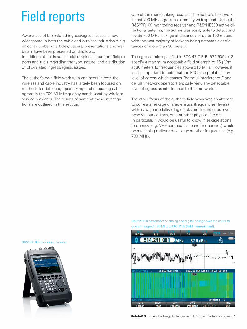
R&S®PR100 screenshot of analog and digital leakage over the entire fre‑
quency range of 120 MHz to 800 MHz (field measurement).
One of the more striking results of the author’s field work is that 700 MHz egress is extremely widespread. Using the R&S®PR100 monitoring receiver and R&S®HE300 active di‑rectional antenna, the author was easily able to detect and locate 700 MHz leakage at distances of up to 100 meters, with the vast majority of leakage being detectable at dis‑tances of more than 30 meters.
The egress limits specified in FCC 47 C.F. R. §76.605(a)12 specify a maximum acceptable field strength of 15 μV/m at 30 meters for frequencies above 216 MHz. However, it is also important to note that the FCC also prohibits any level of egress which causes ”harmful interference,” and cellular network operators typically view any detectable level of egress as interference to their networks.
The other focus of the author’s field work was an attempt to correlate leakage characteristics (frequencies, levels) with leakage modality (ring cracks, enclosure gaps, over‑head vs. buried lines, etc.) or other physical factors. In particular, it would be useful to know if leakage at one frequency (e.g. VHF aeronautical band frequencies) would be a reliable predictor of leakage at other frequencies (e.g. 700 MHz).
Evolving_CATVLTE_bro_en_3606-8514-62.indd 3 16.05.2013 10:56:59
4
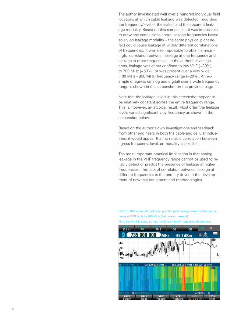
R&S®PR100 screenshot of analog and digital leakage over the frequency
range of 100 MHz to 800 MHz (field measurement).
Note that in this case, egress levels are highly frequency‑dependent.
The author investigated well over a hundred individual field locations at which cable leakage was detected, recording the frequency/level of the leak(s) and the apparent leak‑age modality. Based on this sample set, it was impossible to draw any conclusions about leakage frequencies based solely on leakage modality – the same physical plant de‑fect could cause leakage at widely different combinations of frequencies. It was also impossible to obtain a mean‑ingful correlation between leakage at one frequency and leakage at other frequencies. In the author’s investiga‑tions, leakage was either confined to low VHF (~30%), to 700 MHz (~50%), or was present over a very wide (100 MHz - 800 MHz) frequency range (~20%). An ex‑ample of egress (analog and digital) over a wide frequency range is shown in the screenshot on the previous page.
Note that the leakage levels in this screenshot appear to be relatively constant across the entire frequency range. This is, however, an atypical result. Most often the leakage levels varied significantly by frequency as shown in the screenshot below.
Based on the author’s own investigations and feedback from other engineers in both the cable and cellular indus‑tries, it would appear that no reliable correlation between egress frequency, level, or modality is possible.
The most important practical implication is that analog leakage in the VHF frequency range cannot be used to re‑liably detect or predict the presence of leakage at higher frequencies. This lack of correlation between leakage at different frequencies is the primary driver in the develop‑ment of new test equipment and methodologies.
Evolving_CATVLTE_bro_en_3606-8514-62.indd 4 16.05.2013 10:56:59
Rohde & Schwarz Evolving challenges in LTE / cable interference issues 5
As discussed in [Denisowski], conventional leakage de‑tection tools are incapable of detecting LTE egress in the 700 MHz range. This is due to several factors, including the inability of most of these tools to be tuned to frequen‑cies significantly outside of the VHF aeronautical band (108 MHz to 137 MHz) and their inability to accurately measure the digital QAM signals commonly present at these frequencies.
Various approaches have been proposed for detecting and measuring digital egress at the 700 MHz frequency range. These can be grouped into three major categories: ❙ Insertion of a narrowband carrier ❙ Correlation of QAM signals ❙ Spectral analysis
The simplest of these solutions involves the insertion of a narrowband signal into a digital system. Since most cable operators are unwilling to give up a channel solely for the purpose of signal leakage detection, this narrowband sig‑nal would be inserted between digital QAM signals. The leakage detector would then be tuned to the frequency of this inserted narrowband signal. Physical location of leak‑age is performed using methods similar to those used in analog leakage.
The strengths of this approach are that it is relatively inex‑pensive and is similar to the effective and well‑understood methods used in detecting and measuring narrowband analog leakage at VHF. Furthermore, it allows the flexible placement of the inserted signal at different frequencies – an important feature due to the possibility of the frequen‑cy‑dependent leakage characteristics described previously.
The greatest potential disadvantage of the carrier‑insertion approach is that experience has shown that inserting a narrowband carrier between two digital signals has the potential to degrade the QAM signals [Hranac3]. It is also possible that the inserted carrier could itself become a source of egress interference. The author has personally witnessed several cases in which test carriers inserted into a cable system have themselves created interference to 700 MHz LTE systems.
Test equipment and methodologies
Another proposed methodology involves correlating QAM signals originating at the headend with signals measured in the field. A strong correlation indicates that the mea‑sured signal is egress from the cable system and not a sig‑nal being generated from some other source.
The correlation method does not require a special test channel or carrier. It works with content‑carrying signals at any frequency. This method also does not introduce any new signals into the cable system, so the possibil‑ity of signal degradation or additional test signal egress is non‑existent.
Correlation of the transmitted and received signals re‑quires special equipment at both the headend and in the field. Furthermore, some type of independent data link (cellular wireless) between the headend and the field tester is required to perform correlation. Location of leakage can be performed using traditional methodologies or a time difference of arrival (TDOA) approach.
The most flexible approach for detecting and measuring digital leakage is the use of monitoring receivers: general purpose instruments capable of detecting both digital and analog signals. Monitoring receivers have a very wide frequency range that enables continuous coverage of all cable system frequencies. They provide visualization (spec‑trum and waterfall displays) over any arbitrary frequency range and have integrated radiolocation (direction‑finding) functionality in the form of tone‑based or bearing‑based methodologies.
An additional advantage of monitoring receivers is that they require no intervention or equipment at the headend. They can also be used to detect and measure LTE and oth‑er signals that may be causing ingress interference.
The flexibility and strength of monitoring receivers typically requires a trained operator with a good understanding of radio frequency signal characteristics in order to maxi‑mize their effectiveness. In many cases, a monitoring re‑ceiver would be deployed as a “Tier 2” instrument used by trained technicians or engineers.
Lastly, it should also be noted that these test methodolo‑gies are not mutually exclusive. In many cases various tools can be used to complement each other by leveraging their individual strengths and areas of application.
Evolving_CATVLTE_bro_en_3606-8514-62.indd 5 16.05.2013 10:56:59
6
Public safety developmentsOne of the goals of LTE was to have a standardized radio access technology that would be used by all wireless ser‑vice providers worldwide.Although there are a variety of 3G radio access technolo‑gies such as WCDMA (AT&T/T‑Mobile) and CDMA2000/EVDO (Sprint/Verizon), all wireless service pro‑viders in the United States have standardized on LTE for their 4G networks.
This standardization is not limited to cellular service pro‑viders. LTE has been proposed as a radio access technol‑ogy in many other applications as well, including industrial and military applications. A common air interface enables equipment manufacturers to reduce cost and time‑to‑mar‑ket and facilitates interoperability among a wide variety of devices.
At present, the most important non‑cellular application of LTE (and the one with the greatest possible near‑term ramifications for the cable industry) is in the area of pub‑lic safety. The term “public safety” here refers to police, fire, ambulance, emergency, search and rescue, and other similar local/national government entities charged with preserving the safety of the general public.
New developments in LTE
Historically, public safety communications have been over‑whelmingly voice (narrowband, FM), with an emphasis on rugged handheld and vehicle‑mounted radios. A number of different standards have emerged for digital voice com‑munications (APCO/P25, TETRA, etc.), but system interop‑erability remains elusive. Crises such as the September 11 terrorist attacks and natural disasters (Hurricane Katrina, et al), have pointed out the need for system interoperability among difference services and agencies [Palamara].
The other driving factor for the use of LTE in public safety is the potential to leverage LTE’s high data‑carrying capac‑ity to support advanced applications. For example, first re‑sponders could have immediate, hand‑held access to floor plans, live video, and other critical information. Command and control centers could simultaneously collect and mon‑itor data from a wide variety of responders. A commer‑cially deployed example of this is Motorola’s realtime video intelligence (RTVI).
Although the use of LTE would allow interoperability with public data networks, these public safety LTE networks are intended to operate primarily on their own frequencies. Experience has shown that cellular data networks rapidly reach capacity during emergency (and non‑emergency) situations. In addition to avoiding congestion‑related is‑sues, a separate public safety LTE network can provide better security and quality‑of‑service.
The FCC originally allocated 24 MHz of the 700 MHz band for public safety use, divided into a narrowband and broadband allocation [FCC700]. The narrowband (non‑LTE) public safety allocation was organized into 960 pairs of 6.25 kHz channels (769 MHz to 775 MHz and 799 MHz to 805 MHz). Potential ingress/egress issues for these fre‑quencies are similar to traditional narrowband analog and digital channels.
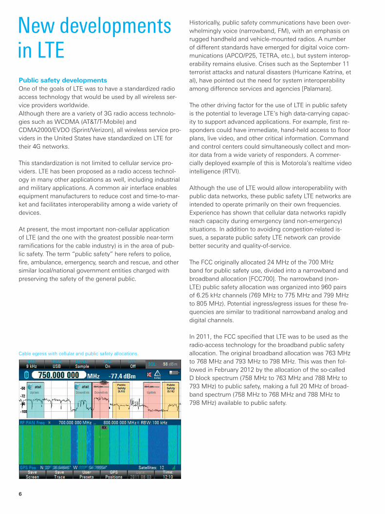
In 2011, the FCC specified that LTE was to be used as the radio‑access technology for the broadband public safety allocation. The original broadband allocation was 763 MHz to 768 MHz and 793 MHz to 798 MHz. This was then fol‑lowed in February 2012 by the allocation of the so‑called D block spectrum (758 MHz to 763 MHz and 788 MHz to 793 MHz) to public safety, making a full 20 MHz of broad‑band spectrum (758 MHz to 768 MHz and 788 MHz to 798 MHz) available to public safety.
Cable egress with cellular and public safety allocations.
Evolving_CATVLTE_bro_en_3606-8514-62.indd 6 16.05.2013 10:56:59
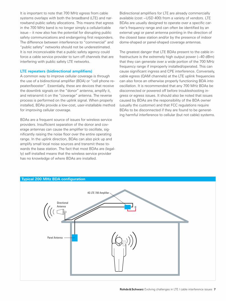
4G LTE 700 Amplifier
Panel Antenna
DirectionalAntenna
Rohde & Schwarz Evolving challenges in LTE / cable interference issues 7
It is important to note that 700 MHz egress from cable systems overlaps with both the broadband (LTE) and nar‑rowband public safety allocations. This means that egress in the 700 MHz band is no longer simply a cellular/cable issue – it now also has the potential for disrupting public safety communications and endangering first responders. The difference between interference to “commercial” and “public safety” networks should not be underestimated. It is not inconceivable that a public safety agency could force a cable service provider to turn off channels that are interfering with public safety LTE networks.
LTE repeaters (bidirectional amplifiers)A common way to improve cellular coverage is through the use of a bidirectional amplifier (BDA) or “cell phone re‑peater/booster”. Essentially, these are devices that receive the downlink signals on the “donor” antenna, amplify it, and retransmit it on the “coverage” antenna. The reverse process is performed on the uplink signal. When properly installed, BDAs provide a low‑cost, user‑installable method for improving cellular coverage.
BDAs are a frequent source of issues for wireless service providers. Insufficient separation of the donor and cov‑erage antennas can cause the amplifier to oscillate, sig‑nificantly raising the noise floor over the entire operating range. In the uplink direction, BDAs can also pick up and amplify small local noise sources and transmit these to‑wards the base station. The fact that most BDAs are (legal‑ly) self‑installed means that the wireless service provider has no knowledge of where BDAs are installed.
Typical 200 MHz BDA configuration
Bidirectional amplifiers for LTE are already commercially available (cost ~USD 400) from a variety of vendors. LTE BDAs are usually designed to operate over a specific car‑rier’s frequency range and can often be identified by an external yagi or panel antenna pointing in the direction of the closest base station and/or by the presence of indoor dome‑shaped or panel‑shaped coverage antennas.
The greatest danger that LTE BDAs present to the cable in‑frastructure is the extremely high output power (~40 dBm) that they can generate over a wide portion of the 700 MHz frequency range if improperly installed/operated. This can cause significant ingress and CPE interference. Conversely, cable egress (QAM channels) at the LTE uplink frequencies can also force an otherwise properly functioning BDA into oscillation. It is recommended that any 700 MHz BDAs be disconnected or powered off before troubleshooting in‑gress or egress issues. It should also be noted that issues caused by BDAs are the responsibility of the BDA owner (usually the customer) and that FCC regulations require BDAs to be disconnected if they are found to be generat‑ing harmful interference to cellular (but not cable) systems.
Evolving_CATVLTE_bro_en_3606-8514-62.indd 7 16.05.2013 10:57:00
8
In order for a femtocell to operate, it must have some type of backhaul connection to the wireless service provider’s core network, and this backhaul is almost universally implemented in the form of an Ethernet/IP connection. Particularly in the case of a residential installation, the Eth‑ernet/IP connection is provided by some type of cable (or xDSL/fiber) modem, meaning that a femtocell and cable modem may be in very close physical proximity to each other. Although both uplink and downlink power levels are substantially lower in femtocell applications (vs. macrocell applications), very close proximity of cable CPE and LTE femtocells can increase the likelihood of both ingress and egress interference [Cobham, Agentschap]. Placing the cable CPE and LTE femtocell as far apart as practically possible would be a good first troubleshooting step when investigating interference issues.
Identifying the presence of a femtocell is another poten‑tial issue. In the case of macrocells installed on towers or other tall structures, the possible presence of a nearby (strong) LTE signal source is relatively easy to identify. Even in the case of hidden or camouflaged base stations/antennas, there are many ways to determine if an LTE macrocell might be nearby, such as signage or cabling. On the other hand, there is usually no external visual indi‑cation that a femtocell is installed at a customer’s site or at an adjoining site, such as a multi‑unit home/apartment building (MDU) or office complex. While LTE femtocells can be designed to recognize other LTE femtocells or macrocells and to adjust their operating parameters to reduce the probability of interference (so‑called self‑or‑ganizing networks), there is no way for cable CPE and LTE femtocells to recognize each other. Studies such as [ANGA] have shown the potential for interference from devices located in neighboring rooms. The lack of an LTE femtocell at the customer’s premises does not therefore mean that LTE femtocells can be ruled out as a possible interference source, especially in multi‑unit structures.
With regards to LTE femtocell deployment in the United States: many equipment manufacturers have either de‑veloped or are in the process of developing LTE‑capable femtocells. In addition, LTE femtocell trials are already un‑derway in Europe and Asia and trials are expected to begin in the United States before the end of 2013 [Electronista]. Based on the trends seen in 3G femtocell rollouts, it should be expected that LTE femtocell deployment will be‑come widespread in the United States within the next 24 to 36 months.
LTE femtocellsIn order to increase their coverage footprint and fill in so‑called coverage holes, wireless service providers can deploy very small base stations at the customer premises (residential or commercial). These small base stations are most commonly referred to as “femtocells,” although the terms “picocell” and “microcell” are also used (there is no industry‑standard definition of these terms). Unlike a cel‑lular repeater, a femtocell does not simply amplify and re‑transmit the uplink and downlink signals: it is a fully func‑tional base station that implements the complete wireless protocol stack and terminates the air interface connection between the user equipment (phone, data card, modem) and the network. Backhaul normally takes place over the customer’s standard Ethernet/IP connection.
Femtocells are purchased directly from the wireless ser‑vice provider and are typically self‑installed. The wireless service provider can provision and monitor the femtocell remotely, and many femtocells contain a GPS receiver to help the provider determine its precise geographical loca‑tion. Most femtocells are designed to cover an average‑sized residence (range ~ 40 feet) and limit the number of subscribers that can connect to the femtocell.
In the United States, AT&T, Verizon, and Sprint offer 3G femtocells. As of 2010, there were more femtocells (350,000) than cell towers (250,000) in the United States [Danno]. Since these femtocells operate on the same fre‑quencies as the “macro” base stations, the potential for cable egress/ingress interference from 3G femtocells has been minimal.
However, the development and deployment of LTE femtocells operating in the 700 MHz band is likely to pres‑ent additional challenges with regards to ingress and egress issues. The two main issues are proximity to the cable equipment and femtocell identification.
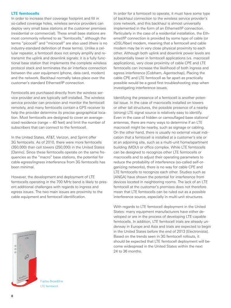
Fujitsu BroadOne
LTE femtocell.
Evolving_CATVLTE_bro_en_3606-8514-62.indd 8 16.05.2013 10:57:00
Rohde & Schwarz Evolving challenges in LTE / cable interference issues 9
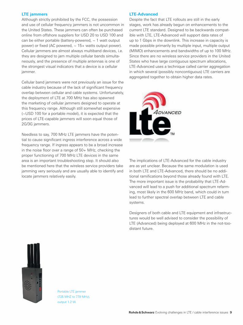
LTE jammersAlthough strictly prohibited by the FCC, the possession and use of cellular frequency jammers is not uncommon in the United States. These jammers can often be purchased online from offshore suppliers for USD 20 to USD 100 and can be either portable (battery‑powered, ~ 1 watt output power) or fixed (AC powered, ~ 15+ watts output power). Cellular jammers are almost always multiband devices, i.e. they are designed to jam multiple cellular bands simulta‑neously, and the presence of multiple antennas is one of the strongest visual indicators that a device is a cellular jammer.
Cellular band jammers were not previously an issue for the cable industry because of the lack of significant frequency overlap between cellular and cable systems. Unfortunately, the deployment of LTE at 700 MHz has also spawned the marketing of cellular jammers designed to operate at this frequency range. Although still somewhat expensive (~USD 100 for a portable model), it is expected that the prices of LTE‑capable jammers will soon equal those of 2G/3G jammers.
Needless to say, 700 MHz LTE jammers have the poten‑tial to cause significant ingress interference across a wide frequency range. If ingress appears to be a broad increase in the noise floor over a range of 50+ MHz, checking the proper functioning of 700 MHz LTE devices in the same area is an important troubleshooting step. It should also be mentioned here that the wireless service providers take jamming very seriously and are usually able to identify and locate jammers relatively easily.
Portable LTE jammer
(725 MHZ to 779 MHz),
output 1.2 W.
LTE-AdvancedDespite the fact that LTE rollouts are still in the early stages, work has already begun on enhancements to the current LTE standard. Designed to be backwards compat‑ible with LTE, LTE‑Advanced will support data rates of up to 1 Gbps in the downlink. This increase in capacity is made possible primarily by multiple input, multiple output (MIMO) enhancements and bandwidths of up to 100 MHz. Since there are no wireless service providers in the United States who have large contiguous spectrum allocations, LTE‑Advanced uses a technique called carrier aggregation in which several (possibly noncontiguous) LTE carriers are aggregated together to obtain higher data rates.
The implications of LTE‑Advanced for the cable industry are as yet unclear. Because the same modulation is used in both LTE and LTE‑Advanced, there should be no addi‑tional ramifications beyond those already found with LTE. The more important issue is the probability that LTE‑Ad‑vanced will lead to a push for additional spectrum refarm‑ing, most likely in the 600 MHz band, which could in turn lead to further spectral overlap between LTE and cable systems.
Designers of both cable and LTE equipment and infrastruc‑tures would be well advised to consider the possibility of LTE (Advanced) being deployed at 600 MHz in the not-too-distant future.
Evolving_CATVLTE_bro_en_3606-8514-62.indd 9 16.05.2013 10:57:00

10
Considerable progress has been made in increasing awareness of potential LTE/cable interference issues. Field work by engineers in the cable, wireless, and test equip‑ment industry has shown that it is difficult to correlate cable leakage at different frequencies and that the leakage modality is not necessarily a good predictor of leakage level or frequency. Several new methods of detecting digi‑tal egress at 700 MHz have been proposed or developed, each with unique strengths and limitations. Developments in the LTE space, such as LTE femtocells, LTE jammers, and LTE‑Advanced will create new challenges for both cable and cellular network operators. Finally, the deploy‑ment of 700 MHz LTE as a public safety technology will increase the importance of reducing ingress and egress issues through proactive maintenance and good engineer‑ing practice.
Conclusion
R&S®PR100 cable TVingress/egress hunter
❙ Wideband analysis covering the entire cable TV spectrum, including MoCA®
❙ Coverage of return path and forward path ❙ Detection of all forms of ingress including that from LTE/4G
❙ No headend equipment required ❙ Realtime FFT analysis, faster than any spectrum analyzer ❙ Handheld and battery operated ❙ Direction finding capability ❙ Built‑in SD card for recording ❙ Built‑in tone generator for measuring signal strength ❙ Waterfall display for detecting intermittent signals of all types
❙ Display easily viewable in direct sunlight
R&S®PR100 monitoring receiver and R&S®HE300 antenna.
Evolving_CATVLTE_bro_en_3606-8514-62.indd 10 16.05.2013 10:57:00
Rohde & Schwarz Evolving challenges in LTE / cable interference issues 11
References
List of abbreviations
❙ [Agentschap] Study of interference to digital cable TV caused by 800 MHz mobile LTE applications. Agentschap Telecom, 27 November 2009.
❙ [ANGA] Beeinflussung der Dienste auf TV-Kabel-Infrastrukturen durch bidirektionale terrestrische Anwendungen LTE (Long Term Evolution) im UHF Bereich. Report by IRT (Institut für Rundfunktechnik GmbH and ANGA, Verband Deutscher Kabelnetzbetreiber e.V.
❙ [Cobham] Field tests investigating the potential interference into Cable TV from LTE deployment in the 800 MHz band. S. Munday and I. Parker. Cobham Technical Services, Report Number 2010‑0792, December 2010.
❙ [Danno] Sprint: We’ve got 250,000 femtocells on our network. Mike Danno. Fierce Wireless, March 23, 2011.
❙ APCO: Association of Public‑Safety Communications Officials
❙ P25: Project 25 ❙ BTOP: Broadband Technology Opportunities Program
❙ BDA: bidirectional amplifier ❙ CDMA2000: code division multiple access (2000) ❙ CPE: customer premises equipment ❙ EVDO: evolution data optimized ❙ FCC: Federal Communications Commission ❙ QAM: quadrature amplitude modulation ❙ GPS: global positioning system ❙ IP: Internet protocol ❙ LTE: long term evolution ❙ MDU: multiple dwelling unit ❙ MIMO: multiple input, multiple output ❙ MoCA®: Multimedia over Coax Alliance ❙ R&S: Rohde & Schwarz trademark® ❙ RTVI: realtime video intelligence ❙ TDOA: time difference of arrival ❙ TETRA: terrestrial trunked radio ❙ WCDMA: wideband code division multiple access ❙ xDSL: digital subscriber line
❙ [Denisowski] Recognizing and Resolving LTE Interference Issues in Cable Networks. Paul Denisowski, Rohde & Schwarz. EXPO 2011 Proceedings.
❙ [Electronista] Verizon preps LTE femtocells, says it hits limits in 2013. Electronista Staff. March 5, 2012.
❙ [FCC700] FCC Encyclopedia : 700 MHz Spectrum. ❙ [Hranac] Some Thoughts on LTE Interference. Ron Hranac, Cisco Systems. Communications Technology. October 1, 2011.
❙ [Hranac2] LTE Interference (Part 2). Ron Hranac, Cisco Systems. Communications Technology. November 1, 2011.
❙ [Hranac3] Broadband: Signal Leakage in an All‑Digital Network. Ron Hranac, Cisco Systems. Communications Technology. February 1, 2009.
❙ [Jackson] BTOP‑funded waiver recipients continue LTE push. Donny Jackson. Urgent Communications. March 13, 2012.
❙ [Palamara] A wander‑ful solution. Maria Palamara and Wim Brouwer. Urgent Communications, March 1, 2011.
Evolving_CATVLTE_bro_en_3606-8514-62.indd 11 16.05.2013 10:57:00
About Rohde & SchwarzRohde & Schwarz is an independent group of companies specializing in electronics. It is a leading supplier of solu-tions in the fields of test and measurement, broadcasting, radiomonitoring and radiolocation, as well as secure communications. Established more than 75 years ago, Rohde & Schwarz has a global presence and a dedicated service network in over 70 countries. Company headquar-ters are in Munich, Germany.
Certified Quality System
ISO 9001
R&S® is a registered trademark of Rohde & Schwarz GmbH & Co. KG
Trade names are trademarks of the owners | Printed in Germany (fi)
PD 3606.8514.62 | Version 01.00 | May 2013 | Evolving CATVLTE
Data without tolerance limits is not binding | Subject to change
© 2013 Rohde & Schwarz GmbH & Co. KG | 81671 München, Germany
Regional contact ❙ Europe, Africa, Middle East | +49 89 4129 12345 [email protected]
❙ North America | 1 888 TEST RSA (1 888 837 87 72) [email protected]
❙ Latin America | +1 410 910 79 88 [email protected]
❙ Asia/Pacific | +65 65 13 04 88 [email protected]
❙ China | +86 800 810 8228/+86 400 650 5896 [email protected]
Rohde & Schwarz GmbH & Co. KGwww.rohde-schwarz.com
Environmental commitment ❙ Energy-efficient products ❙ Continuous improvement in environmental sustainability ❙ ISO 14001-certified environmental management system
Service you can rely on❙ Worldwide ❙ Local and personalized❙ Customized and flexible❙ Uncompromising quality ❙ Long-term dependability
3606851462
Evolving_CATVLTE_bro_en_3606-8514-62.indd 12 16.05.2013 10:57:00


![DEPOSITION TITLE AND INDEX FORM [FORMAT] · Web viewAnd by understanding how LTE is evolving, how commercial service providers are using LTE is a great way to be able to anticipate](https://img.pdfslide.net/doc/110x75/5e8bef5a7cc64b3e824a3b03/deposition-title-and-index-form-format-web-view-and-by-understanding-how-lte-is.jpg)
![A Refer^encias Bibliogr a cas - DBD PUC · PDF file... Nokia Siemens Networks Flexi Multiradio BTS. C [34]Parkvall, Stefan and Dahlman, Erik and ... LTE-Advanced and Evolving LTE towards](https://img.pdfslide.net/doc/110x75/5a70fa6b7f8b9a9d538c7df1/a-referencias-bibliogr-a-cas-dbd-puc-riowww2dbdpuc-riobrpergamumtesesabertas11215152013postextupdf.jpg)