Embed Size (px)
Citation preview

1BRUSHLAND BIODIGESTER MANUAL
M435m Mattos, Luis CláudioBrushland biodigester manual: sustainable management of land in the Brushland Project /
Luis Cláudio Mattos, Mário Farias Júnior. – Recife, PE: Dom Helder Camara Project, 2012.50 p. : il.
ISBN: 978-85-64154-02-5
1. Biodigester 2. Biogas 3. Environment 4. Alternative Sources of Energy 5. Family Agriculture 6. Appropriate Technology 7. Agricultural Innovations I. Farias Júnior, Mário II.
Title.
CDU 662.767.2 (2. ed.) CDD 665.776 (22. ed.)
International Catalogued Data in the Publication – CIPAna Catarina Macêdo CRB-4/1781
President of the Republic: Dilma Rousseff
Minister of State for Agricultural Development: Pepe Vargas
Executive Secretary of the Ministry of Agrarian Development: Márcia Quadrado
National Secretary of Family Agriculture: Laudemir André Müller
National Secretary of Territorial Development: Jerônimo Rodrigues Souza
National Secretary of Agrarian Reform: Adhemar Lopes de Almeida
Coordinator of the Nucleus for Agrarian Studies and Rural Development (NEAD): Joaquim Calheiros Soriano
President of the National Institute of Colonisation and Agrarian Reform (INCRA): Celso Lisboa de Lacerda
Head of the Office of the Minister of State for Agrarian Development: Gerson Ben
Coordinator of Social Communications for MDA: Ansélio Angelo Brustolin
Coordinator of Journalism for ASCOM/MDA: Ludmilla Duarte Santana e Souza
ASCOM/MDA Administrative Coordinator: Ila Baraúna Mendes
Communications Advisor for the Minister of Agrarian Development: Silvana Gonçalves
Head of the Communications Consultancy for INCRA: Walmaro Tirso Zancan Paz
Dom Helder Camara Project Director: Espedito Rufino
Technical Execution: Mário Farias Jr.
Texts: Luis Cláudio Mattos
Photographs: Antônio Melcop, Diaconia Arquives & PDHC Arquives
Ilustrations: Luis Cláudio Mattos (using SketchUp 8)
Cover Photo: Antônio Melcop
Graphic Project: Tríade Design
Translation: Michael Mc Laughlin
Revision: Sarah Bailey
Production: Dom Helder Camara Project
Territorial Department of Development Ministry of Agrarian Development
Brazilian Government
Co-Prodution: Diaconia
Support: FIDA, GEF & Norwegian Church Aid
This Edition: 3,000 copies
(download available atwww.projetodomhelder.gov.br e www.diaconia.org.br)
Special thanks to Ismael Mendes, Iracy Souza, Geraldo Nobre, Maria Nobre, Espedito Rufino, Felipe Jalfim, Jucier Jorge, Joseilton Evangelista, Adriana Amâncio, Ricardo Blackburn,Tainah Regueira, Joel Krehbiel, Gilmar and Maria da Paz Galdino Genésio
(cover) and to all those who directly or indirectly contributed to this publication.
PROLOGUE
It is with pleasure and satisfaction that the Dom Helder Camara Project (PDHC) and Diaconia launch this handbook on Biodigesters.
This is one of the initiatives of the Dom Helder Camara Project – The Department of Agrarian Development, The International Fund for the Development of Agriculture (FIDA) and Global Environment Facility (GEF) - in partnership with Diaconia in the Brazilian Semiarid Region.
Motivated by investments made by the PDHC and its partnership network of Ongoing Technical Consultancy, many families have aroused their interest in setting up biodigesters as a strong alternative or complement to biogas fuel, replacing firewood, charcoal and liquefied petroleum gas (LPG), which have the greatest impact on the environment.
This work is also, and mainly, due to the efforts of experimentation and investigation on the part of men and women farmers on the land. With their local knowledge and observation capabilities, combined to the technical support of partner organisations to enhance their lifestyles; proving that it is possible to promote development in the region, while at the same time preserving the environment.
One of the success factors of the biodigester model presented here is related to its characteristics. The low cost, the use of materials available in the local builders’ hardware stores, and the easy maintenance facilitate greatly to their reproduction in the brushland countryside. The benefited families who own this model of the biodigester express satisfaction when reporting the effects it has on various aspects of domestic life.
The main motivation for publishing this manual is to offer a record of the state of the art of these biodigesters, making this technology accessible to other agricultural families within and outside the Semiarid Region.
Espedito Rufino Armindo Klumb
Dom Helder Camara Project Director Diaconia Executive Director
SUMMARy
PROLOGUE 5
INTRODUCTION 6
WHAT IS A BIODIGESTER? 7
A POSITIVE CONTRIBUTION TO FARMING 8
HOW TO BUILD A BIODIGESTER 10
Choice of site and excavation 10
Making the concrete slabs 12
Biodigester concrete slab tank 14
Input tank 24
The outlet system 25
Biocombustion chamber (fibre tank) 27
Gaspipe 37
Adaptation of stove 45
MANAGING A BIODIGESTER 47
Greenhouse gas emissions (ghg) 49
APPENDIX 52
THE EXPERIENCE OF ISMAEL MENDES AND HIS FAMILy 54
6 7BRUSHLAND BIODIGESTER MANUAL
INTRODUCTION
The advance of deforestation and the destruction of scrub vegetation have generated a growing concern about conservation strategies for the biome.
Domestic use of unsustainable firewood is a major cause for the disappearance of the vegetation. Many families in rural areas, due to deforestation which leads to difficulty in obtaining firewood, have already adopted gas stoves – Liquefied Petroleum Gas or LPG – a fossil fuel and therefore non-renewable. But even though firewood is potentially a renewable source of energy, in general its use has been anything but rational, well above Nature’s capacity for renewing vegetation.
In other words, if before, the use of firewood or charcoal meant at least the farmer had his own source of energy, the use of LPG as a source of energy currently represents a factor of dependence on the part of rural households in the region. The replacement of firewood and charcoal by LPG has therefore impacts on the domestic economy, and is a worrying factor for some families.
The setting up of biodigesters is a positive answer to these questions. The dung, which is the raw material for the production of biogas is produced on the property where the biodigester is installed. This maintains the autonomy of the family with regard to the main domestic fuel. In addition, the simple maintenance does not compromise the other activities of the production unit. The volume of biogas, combined with its properties meets the demand with quality and efficiency.
This manual presents in detail the structure of the proposed biodigester, indicating the parts and specifying the material needed for its construction. One of the final chapters explains the handling of the biodigester and another contains a brief account on the balance of emissions of greenhouse gases based on a projection studied by the Dom Helder Camara Project team.
WHAT IS A BIODIGESTER?
A digester is a device that transforms cattle manure into inflammable gas (Biogas), which can replace the cooking gas bought in canisters (Liquefied Petroleum Gas or LPG).
Biogas is a mixture of several types of gases. Methane, the main component of biogas, has no smell, colour or taste, but the other gases in the mixture may give off a slight odour of garlic or rotten eggs, which through a simple process of filtration can be easily removed from the Biogas composition. One can safely state that the use of biogas in the kitchen is hygienic, does not release fumes and leaves no residue in the pans.
The process of generating biogas is performed by microorganisms (bacteria) that exist in the dung itself, and happens naturally when the dung is in an environment where there is no oxygen. After passing through the biodigester, the manure is transformed into a gaseous quantum (biogas), a liquid and another solid. The latter are by-products that can be used as nutrients in agriculture and /or fish farming.
Biodigesters are not new in Brazil. They were introduced into the country based on models from China and India. The model presented in this manual is taken from the Indian model, but adapted to the materials available in almost every country town builders’ hardware store in Brazil. And the technology applied to the concrete slab cisterns, widely disseminated over the Brazilian Semiarid Region, is also used.
8 9BRUSHLAND BIODIGESTER MANUAL
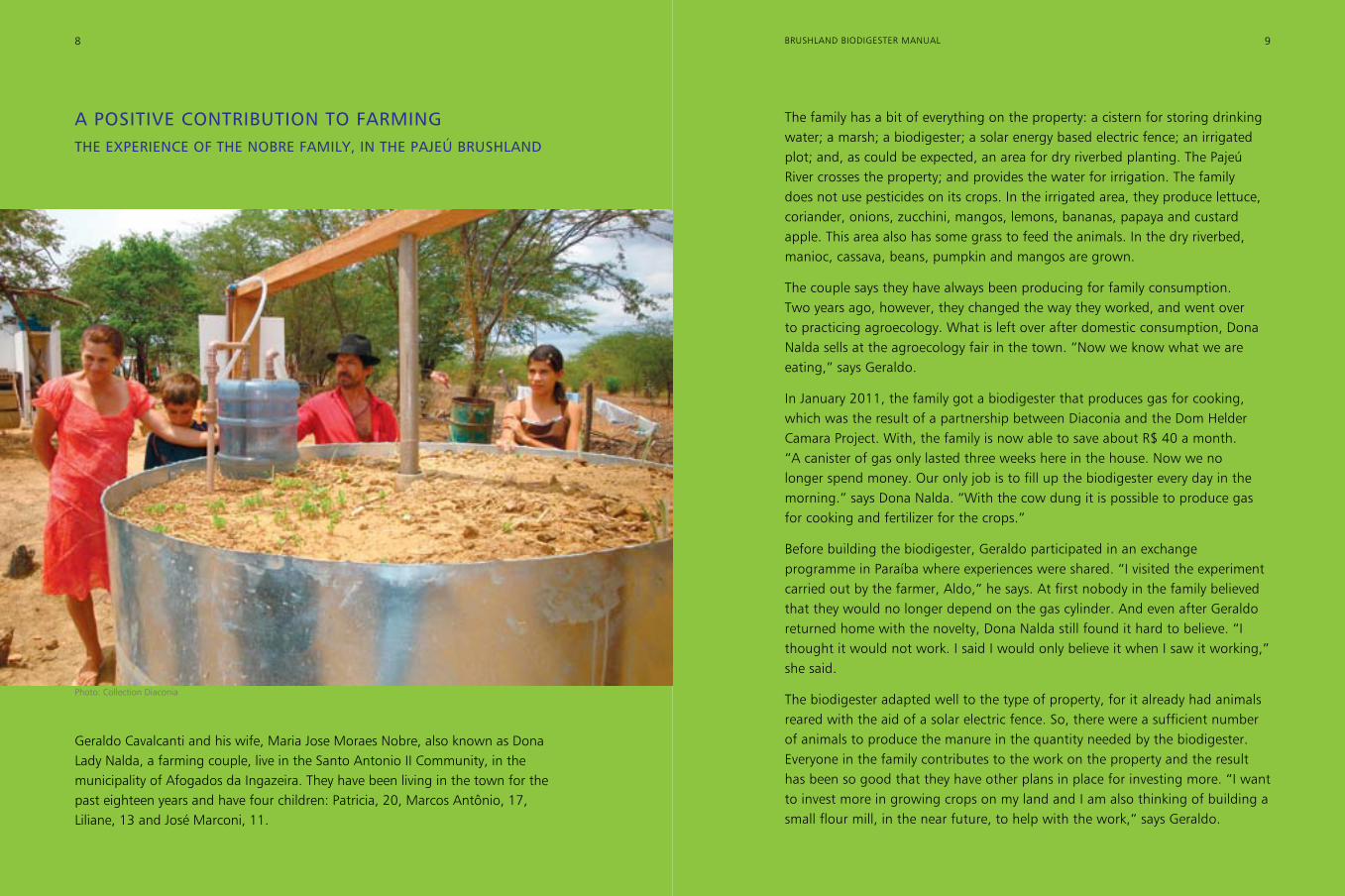
A POSITIVE CONTRIBUTION TO FARMINGTHE EXPERIENCE OF THE NOBRE FAMILy, IN THE PAJEÚ BRUSHLAND
The family has a bit of everything on the property: a cistern for storing drinking water; a marsh; a biodigester; a solar energy based electric fence; an irrigated plot; and, as could be expected, an area for dry riverbed planting. The Pajeú River crosses the property; and provides the water for irrigation. The family does not use pesticides on its crops. In the irrigated area, they produce lettuce, coriander, onions, zucchini, mangos, lemons, bananas, papaya and custard apple. This area also has some grass to feed the animals. In the dry riverbed, manioc, cassava, beans, pumpkin and mangos are grown.
The couple says they have always been producing for family consumption. Two years ago, however, they changed the way they worked, and went over to practicing agroecology. What is left over after domestic consumption, Dona Nalda sells at the agroecology fair in the town. “Now we know what we are eating,” says Geraldo.
In January 2011, the family got a biodigester that produces gas for cooking, which was the result of a partnership between Diaconia and the Dom Helder Camara Project. With, the family is now able to save about R$ 40 a month. “A canister of gas only lasted three weeks here in the house. Now we no longer spend money. Our only job is to fill up the biodigester every day in the morning.” says Dona Nalda. “With the cow dung it is possible to produce gas for cooking and fertilizer for the crops.”
Before building the biodigester, Geraldo participated in an exchange programme in Paraíba where experiences were shared. “I visited the experiment carried out by the farmer, Aldo,” he says. At first nobody in the family believed that they would no longer depend on the gas cylinder. And even after Geraldo returned home with the novelty, Dona Nalda still found it hard to believe. “I thought it would not work. I said I would only believe it when I saw it working,” she said.
The biodigester adapted well to the type of property, for it already had animals reared with the aid of a solar electric fence. So, there were a sufficient number of animals to produce the manure in the quantity needed by the biodigester. Everyone in the family contributes to the work on the property and the result has been so good that they have other plans in place for investing more. “I want to invest more in growing crops on my land and I am also thinking of building a small flour mill, in the near future, to help with the work,” says Geraldo.
Geraldo Cavalcanti and his wife, Maria Jose Moraes Nobre, also known as Dona Lady Nalda, a farming couple, live in the Santo Antonio II Community, in the municipality of Afogados da Ingazeira. They have been living in the town for the past eighteen years and have four children: Patricia, 20, Marcos Antônio, 17, Liliane, 13 and José Marconi, 11.
8 9BRUSHLAND BIODIGESTER MANUAL
Photo: Collection Diaconia
10 11BRUSHLAND BIODIGESTER MANUAL
HOW TO BUILD A BIODIGESTER?
CHOICE OF SITE AND EXCAVATION
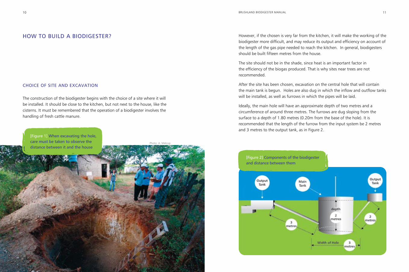
The construction of the biodigester begins with the choice of a site where it will be installed. It should be close to the kitchen, but not next to the house, like the cisterns. It must be remembered that the operation of a biodigester involves the handling of fresh cattle manure.
However, if the chosen is very far from the kitchen, it will make the working of the biodigester more difficult, and may reduce its output and efficiency on account of the length of the gas pipe needed to reach the kitchen. In general, biodigesters should be built fifteen metres from the house.
The site should not be in the shade, since heat is an important factor in the efficiency of the biogas produced. That is why sites near trees are not recommended.
After the site has been chosen, excavation on the central hole that will contain the main tank is begun. Holes are also dug in which the inflow and outflow tanks will be installed, as well as furrows in which the pipes will be laid.
Ideally, the main hole will have an approximate depth of two metres and a circumference of around three metres. The furrows are dug sloping from the surface to a depth of 1.80 metres (0.20m from the base of the hole). It is recommended that the length of the furrow from the input system be 2 metres and 3 metres to the output tank, as in Figure 2.
[Figure 2] Components of the biodigester and distance between them
[Figure 1] When excavating the hole, care must be taken to observe the distance between it and the house
Photo: A. Melcop
12 13BRUSHLAND BIODIGESTER MANUAL
MAKING THE CONCRETE SLABS
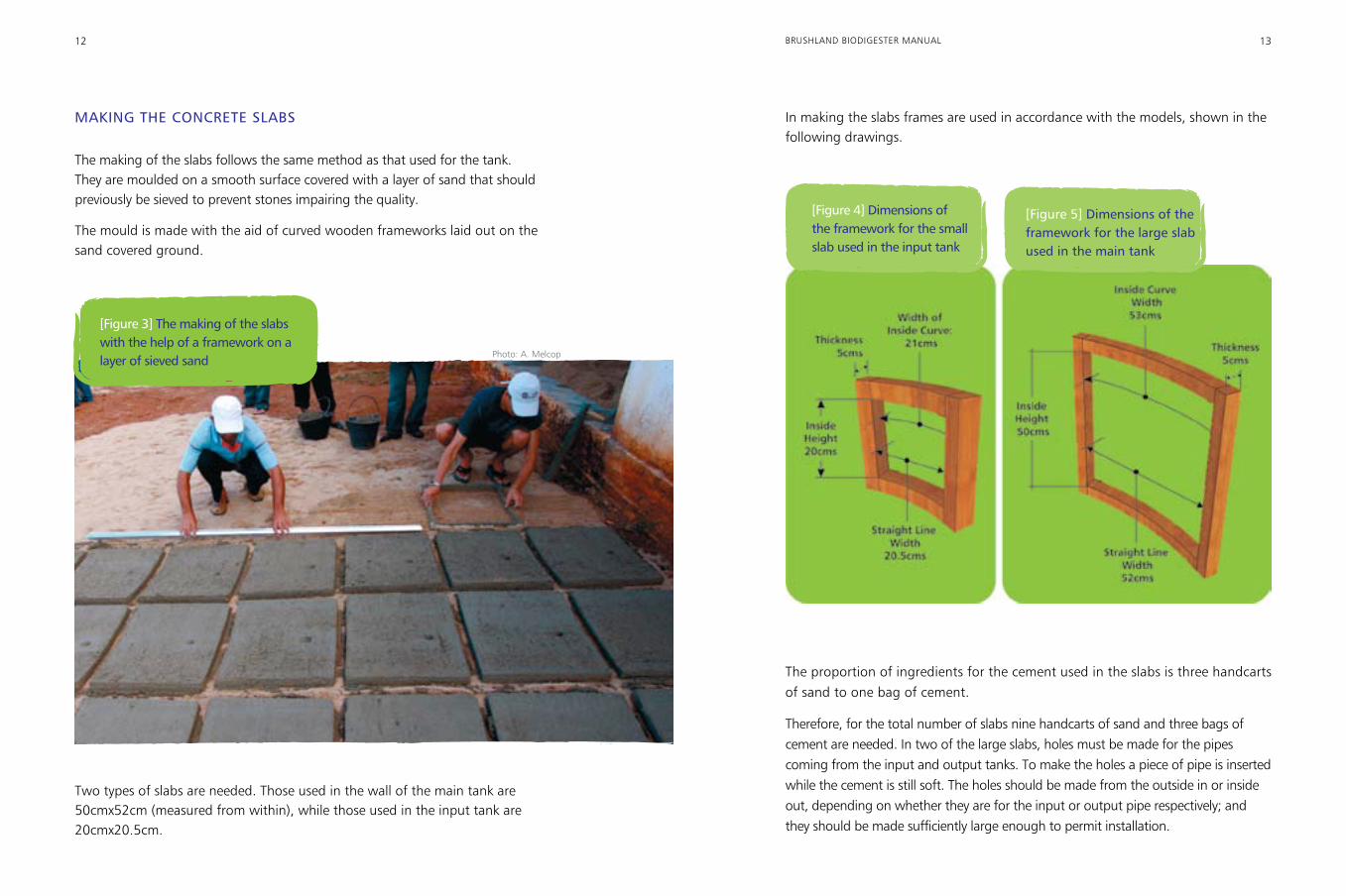
The making of the slabs follows the same method as that used for the tank. They are moulded on a smooth surface covered with a layer of sand that should previously be sieved to prevent stones impairing the quality.
The mould is made with the aid of curved wooden frameworks laid out on the sand covered ground.
In making the slabs frames are used in accordance with the models, shown in the following drawings.
Two types of slabs are needed. Those used in the wall of the main tank are 50cmx52cm (measured from within), while those used in the input tank are 20cmx20.5cm.
The proportion of ingredients for the cement used in the slabs is three handcarts of sand to one bag of cement.
Therefore, for the total number of slabs nine handcarts of sand and three bags of cement are needed. In two of the large slabs, holes must be made for the pipes coming from the input and output tanks. To make the holes a piece of pipe is inserted while the cement is still soft. The holes should be made from the outside in or inside out, depending on whether they are for the input or output pipe respectively; and they should be made sufficiently large enough to permit installation.
[Figure 4] Dimensions of the framework for the small slab used in the input tank
[Figure 5] Dimensions of the framework for the large slab used in the main tank
[Figure 3] The making of the slabs with the help of a framework on a layer of sieved sand Photo: A. Melcop
14 15BRUSHLAND BIODIGESTER MANUAL
Next, while the concrete slabs are drying out, the construction of the other components of the biodigester is begun.
BIODIGESTER CONCRETE SLAB TANK
Floor
The bottom of the hole should be as level as possible to allow the construction of a floor. If, at a depth of two metres, the soil is full of stones, they must be removed or broken up so that the floor is level. In the case of clay, the floor should be compacted, using a mallet. After levelling, the mortar for the floor is prepared with cement, sand and gravel in the proportion of three wheelbarrows of sand, two of gravel and one bag of cement. The floor should be levelled, using a plumb line, to guarantee it is perfectly level.
If the ground is soft, formed for example of sand or loose clay, one may opt to build the floor with an iron frame (a “grid”) made in the shape of a two metre circle with iron rods and placed in the centre of the hole. When this is completed, make a cross with two other pieces of iron rod.
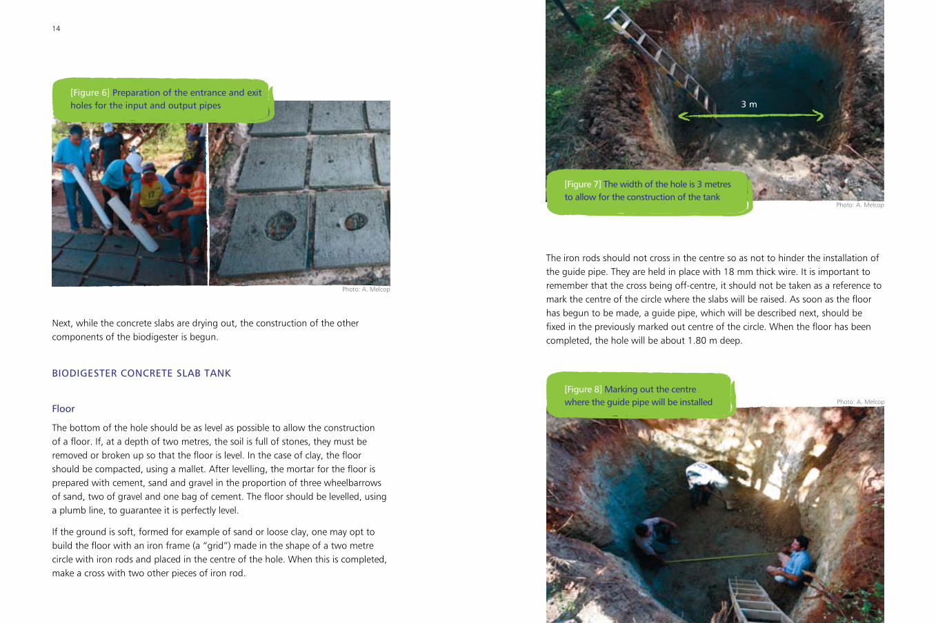
The iron rods should not cross in the centre so as not to hinder the installation of the guide pipe. They are held in place with 18 mm thick wire. It is important to remember that the cross being off-centre, it should not be taken as a reference to mark the centre of the circle where the slabs will be raised. As soon as the floor has begun to be made, a guide pipe, which will be described next, should be fixed in the previously marked out centre of the circle. When the floor has been completed, the hole will be about 1.80 m deep.
[Figure 7] The width of the hole is 3 metres to allow for the construction of the tank
3 m
[Figure 8] Marking out the centre where the guide pipe will be installed
[Figure 6] Preparation of the entrance and exit holes for the input and output pipes
Photo: A. Melcop
Photo: A. Melcop
Photo: A. Melcop
16 17BRUSHLAND BIODIGESTER MANUAL
Guide Pipe (centre)
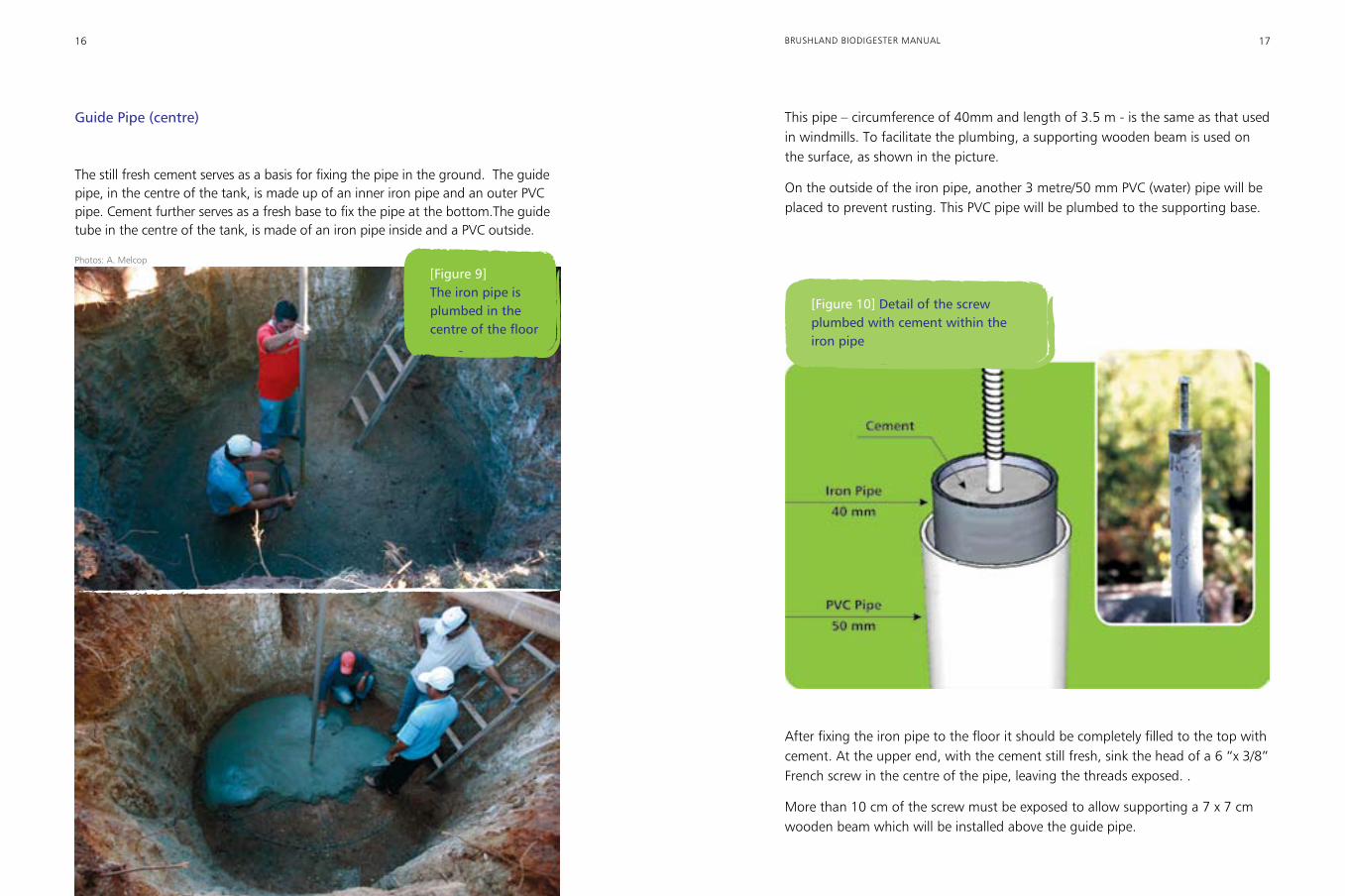
The still fresh cement serves as a basis for fixing the pipe in the ground. The guide pipe, in the centre of the tank, is made up of an inner iron pipe and an outer PVC pipe. Cement further serves as a fresh base to fix the pipe at the bottom.The guide tube in the centre of the tank, is made of an iron pipe inside and a PVC outside.
This pipe – circumference of 40mm and length of 3.5 m - is the same as that used in windmills. To facilitate the plumbing, a supporting wooden beam is used on the surface, as shown in the picture.
On the outside of the iron pipe, another 3 metre/50 mm PVC (water) pipe will be placed to prevent rusting. This PVC pipe will be plumbed to the supporting base.
[Figure 9] The iron pipe is plumbed in the centre of the floor
[Figure 10] Detail of the screw plumbed with cement within the iron pipe
After fixing the iron pipe to the floor it should be completely filled to the top with cement. At the upper end, with the cement still fresh, sink the head of a 6 “x 3/8” French screw in the centre of the pipe, leaving the threads exposed. .
More than 10 cm of the screw must be exposed to allow supporting a 7 x 7 cm wooden beam which will be installed above the guide pipe.
Photos: A. Melcop
18 19BRUSHLAND BIODIGESTER MANUAL
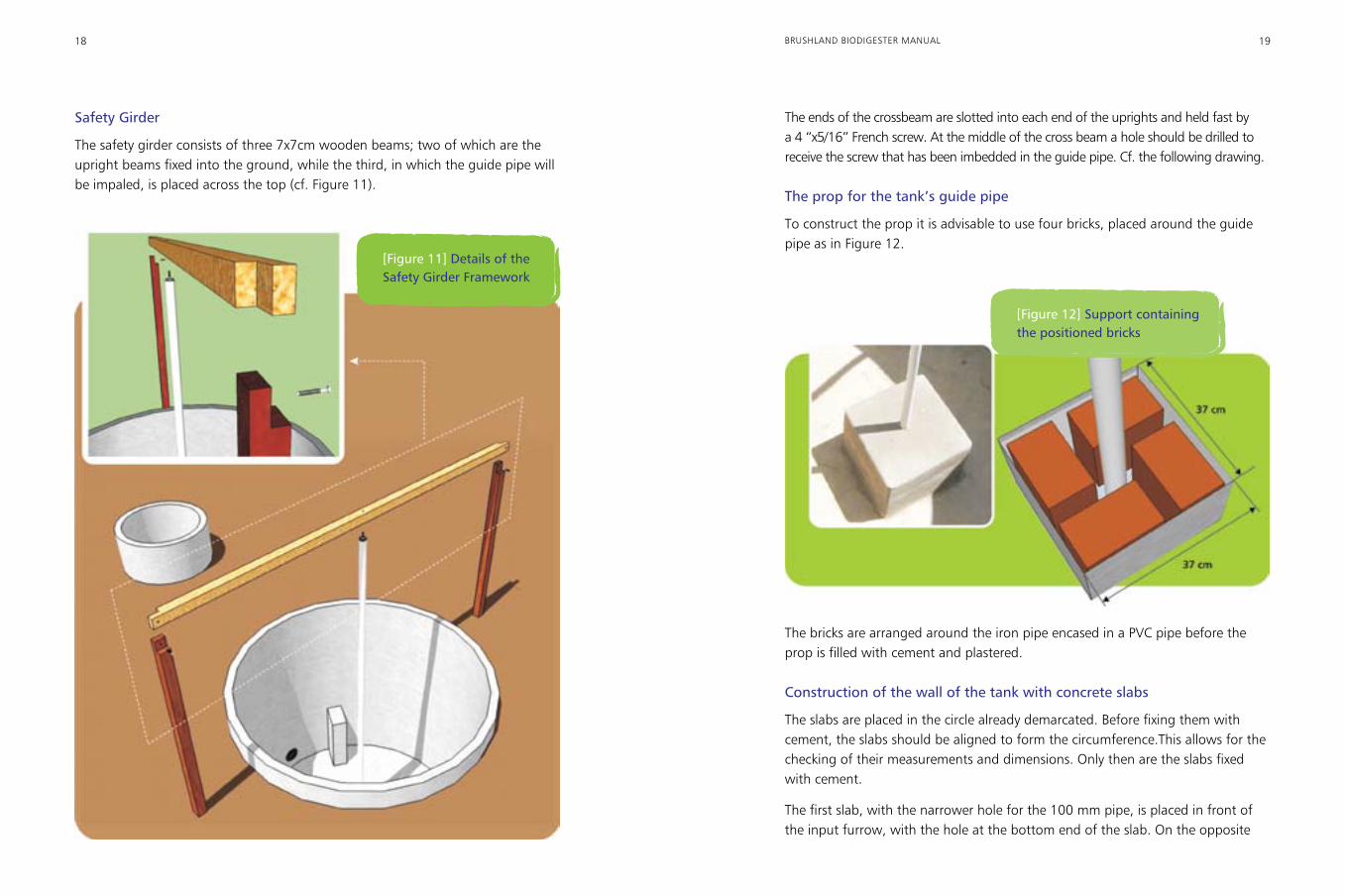
Safety Girder
The safety girder consists of three 7x7cm wooden beams; two of which are the upright beams fixed into the ground, while the third, in which the guide pipe will be impaled, is placed across the top (cf. Figure 11).
The ends of the crossbeam are slotted into each end of the uprights and held fast by a 4 “x5/16” French screw. At the middle of the cross beam a hole should be drilled to receive the screw that has been imbedded in the guide pipe. Cf. the following drawing.
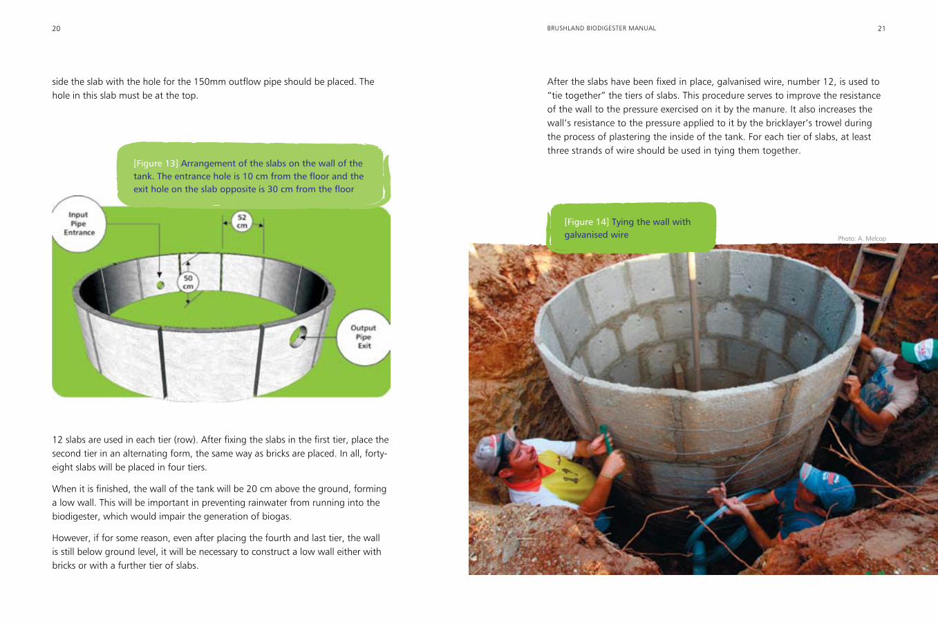
The prop for the tank’s guide pipe
To construct the prop it is advisable to use four bricks, placed around the guide pipe as in Figure 12.
[Figure 11] Details of the Safety Girder Framework
The bricks are arranged around the iron pipe encased in a PVC pipe before the prop is filled with cement and plastered.
Construction of the wall of the tank with concrete slabs
The slabs are placed in the circle already demarcated. Before fixing them with cement, the slabs should be aligned to form the circumference.This allows for the checking of their measurements and dimensions. Only then are the slabs fixed with cement.
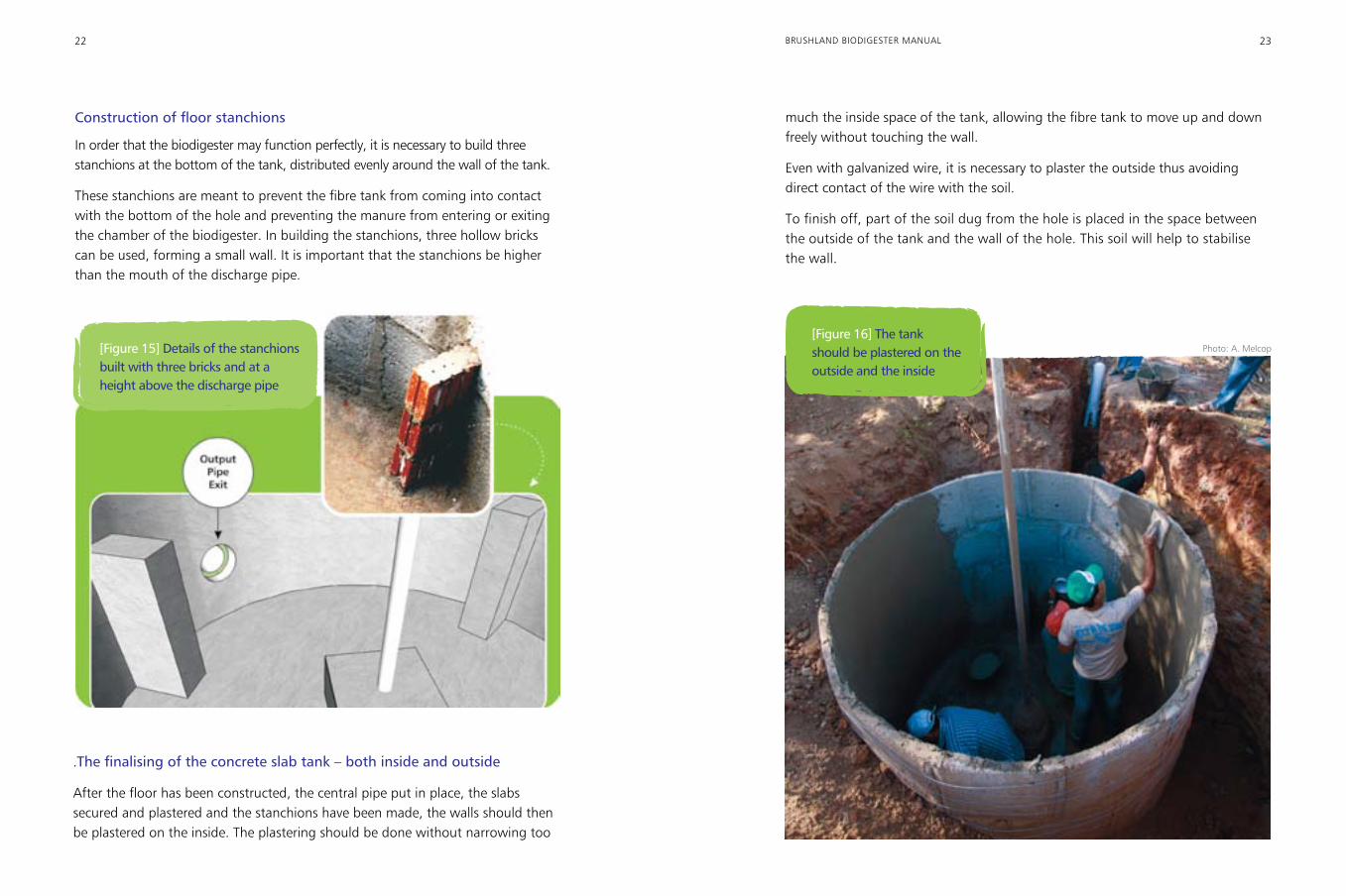
The first slab, with the narrower hole for the 100 mm pipe, is placed in front of the input furrow, with the hole at the bottom end of the slab. On the opposite
[Figure 12] Support containing the positioned bricks
20 21BRUSHLAND BIODIGESTER MANUAL
side the slab with the hole for the 150mm outflow pipe should be placed. The hole in this slab must be at the top.
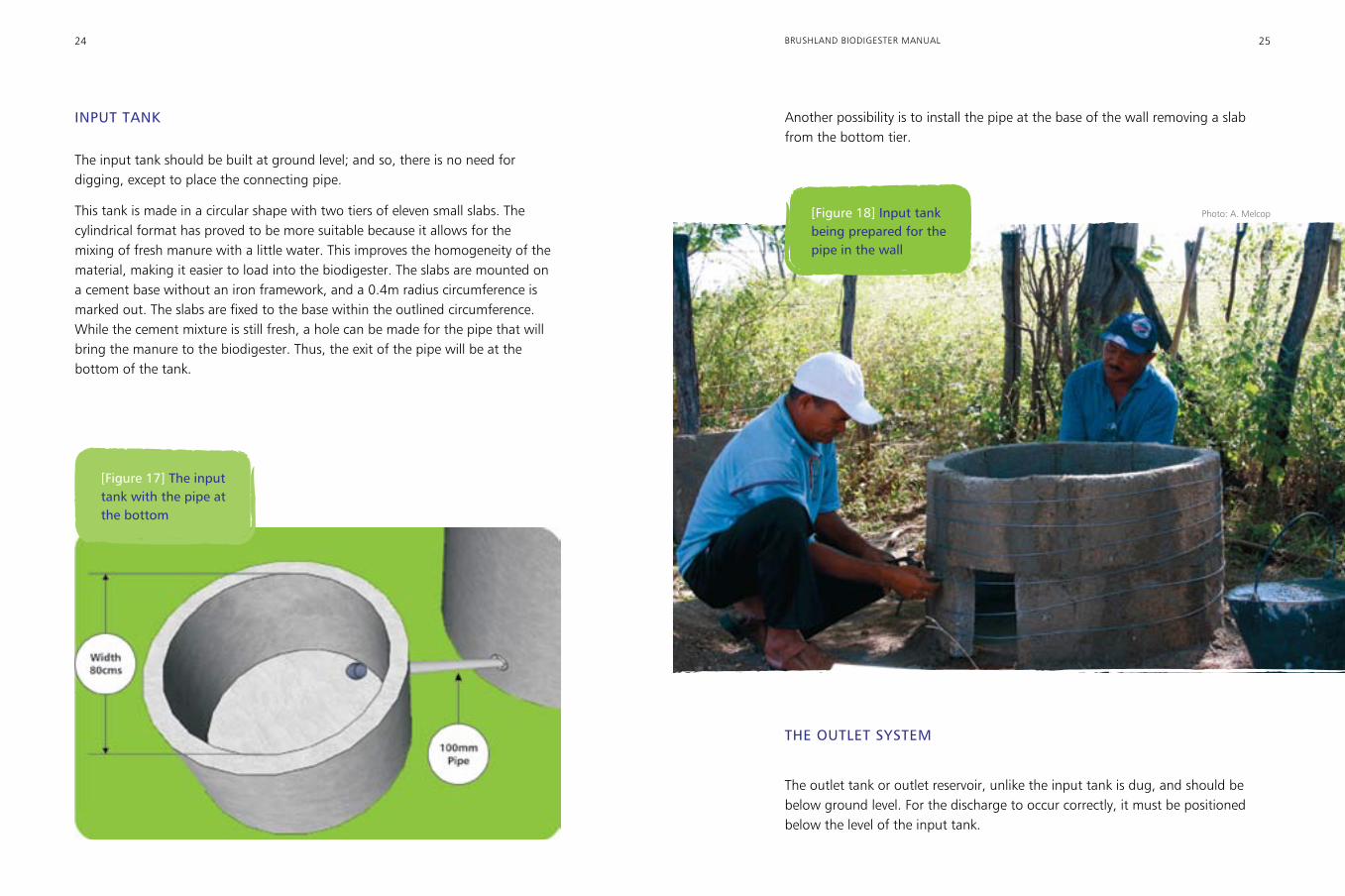
After the slabs have been fixed in place, galvanised wire, number 12, is used to “tie together” the tiers of slabs. This procedure serves to improve the resistance of the wall to the pressure exercised on it by the manure. It also increases the wall’s resistance to the pressure applied to it by the bricklayer’s trowel during the process of plastering the inside of the tank. For each tier of slabs, at least three strands of wire should be used in tying them together.
[Figure 13] Arrangement of the slabs on the wall of the tank. The entrance hole is 10 cm from the floor and the exit hole on the slab opposite is 30 cm from the floor
12 slabs are used in each tier (row). After fixing the slabs in the first tier, place the second tier in an alternating form, the same way as bricks are placed. In all, forty-eight slabs will be placed in four tiers.
When it is finished, the wall of the tank will be 20 cm above the ground, forming a low wall. This will be important in preventing rainwater from running into the biodigester, which would impair the generation of biogas.
However, if for some reason, even after placing the fourth and last tier, the wall is still below ground level, it will be necessary to construct a low wall either with bricks or with a further tier of slabs.
[Figure 14] Tying the wall with galvanised wire Photo: A. Melcop
22 23BRUSHLAND BIODIGESTER MANUAL
Construction of floor stanchions
In order that the biodigester may function perfectly, it is necessary to build three stanchions at the bottom of the tank, distributed evenly around the wall of the tank.
These stanchions are meant to prevent the fibre tank from coming into contact with the bottom of the hole and preventing the manure from entering or exiting the chamber of the biodigester. In building the stanchions, three hollow bricks can be used, forming a small wall. It is important that the stanchions be higher than the mouth of the discharge pipe.
much the inside space of the tank, allowing the fibre tank to move up and down freely without touching the wall.
Even with galvanized wire, it is necessary to plaster the outside thus avoiding direct contact of the wire with the soil.
To finish off, part of the soil dug from the hole is placed in the space between the outside of the tank and the wall of the hole. This soil will help to stabilise the wall.
[Figure 15] Details of the stanchions built with three bricks and at a height above the discharge pipe
.The finalising of the concrete slab tank – both inside and outside
After the floor has been constructed, the central pipe put in place, the slabs secured and plastered and the stanchions have been made, the walls should then be plastered on the inside. The plastering should be done without narrowing too
[Figure 16] The tank should be plastered on the outside and the inside
Photo: A. Melcop
24 25BRUSHLAND BIODIGESTER MANUAL
INPUT TANK
The input tank should be built at ground level; and so, there is no need for digging, except to place the connecting pipe.
This tank is made in a circular shape with two tiers of eleven small slabs. The cylindrical format has proved to be more suitable because it allows for the mixing of fresh manure with a little water. This improves the homogeneity of the material, making it easier to load into the biodigester. The slabs are mounted on a cement base without an iron framework, and a 0.4m radius circumference is marked out. The slabs are fixed to the base within the outlined circumference. While the cement mixture is still fresh, a hole can be made for the pipe that will bring the manure to the biodigester. Thus, the exit of the pipe will be at the bottom of the tank.
Another possibility is to install the pipe at the base of the wall removing a slab from the bottom tier.
[Figure 17] The input tank with the pipe at the bottom
THE OUTLET SySTEM
The outlet tank or outlet reservoir, unlike the input tank is dug, and should be below ground level. For the discharge to occur correctly, it must be positioned below the level of the input tank.
[Figure 18] Input tank being prepared for the pipe in the wall
Photo: A. Melcop
26 27BRUSHLAND BIODIGESTER MANUAL
Gravel
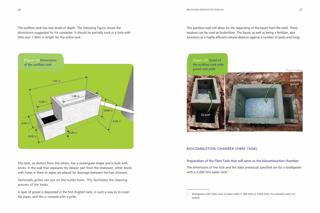
The outflow tank has two levels of depth. The following Figure shows the dimensions suggested for his container. It should be partially sunk in a hole with little over 1.60m in length for the entire tank.
This partition wall will allow for the separating of the liquid from the solid. These residues can be used as biofertilizer. The liquid, as well as being a fertilizer, also functions as a highly efficient natural defence against a number of pests and fungi.
[Figure 19] Dimensions of the outflow tank
This tank, as distinct from the others, has a rectangular shape and is built with bricks. In the wall that separates the deeper part from the shallower, either bricks with holes in them or pipes are placed for drainage between the two divisions.
Optionally grilles can put on the outlet holes. This facilitates the cleaning process of the tanks.
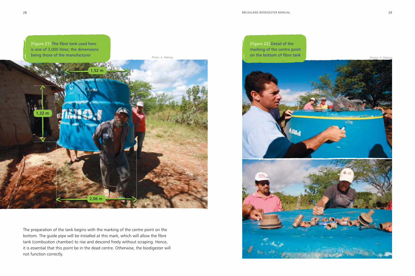
A layer of gravel is deposited in the first (higher) tank, in such a way as to cover the pipes; and this is covered with a grille.
Grille covering gravel
[Figure 20] Detail of the outflow tank with gravel and grille
BIOCOMBUSTION CHAMBER (FIBRE TANK)
Preparation of the Fibre Tank that will serve as the biocombustion chamber.
The dimensions of the hole and the slabs previously specified are for a biodigester with a 3,000 litre water tank1.
1 Biodigesters with other sizes of water tanks (1,000 litres or 5,000 litres, for example) were not
tested).
Photo: A. Melcop
28 29BRUSHLAND BIODIGESTER MANUAL
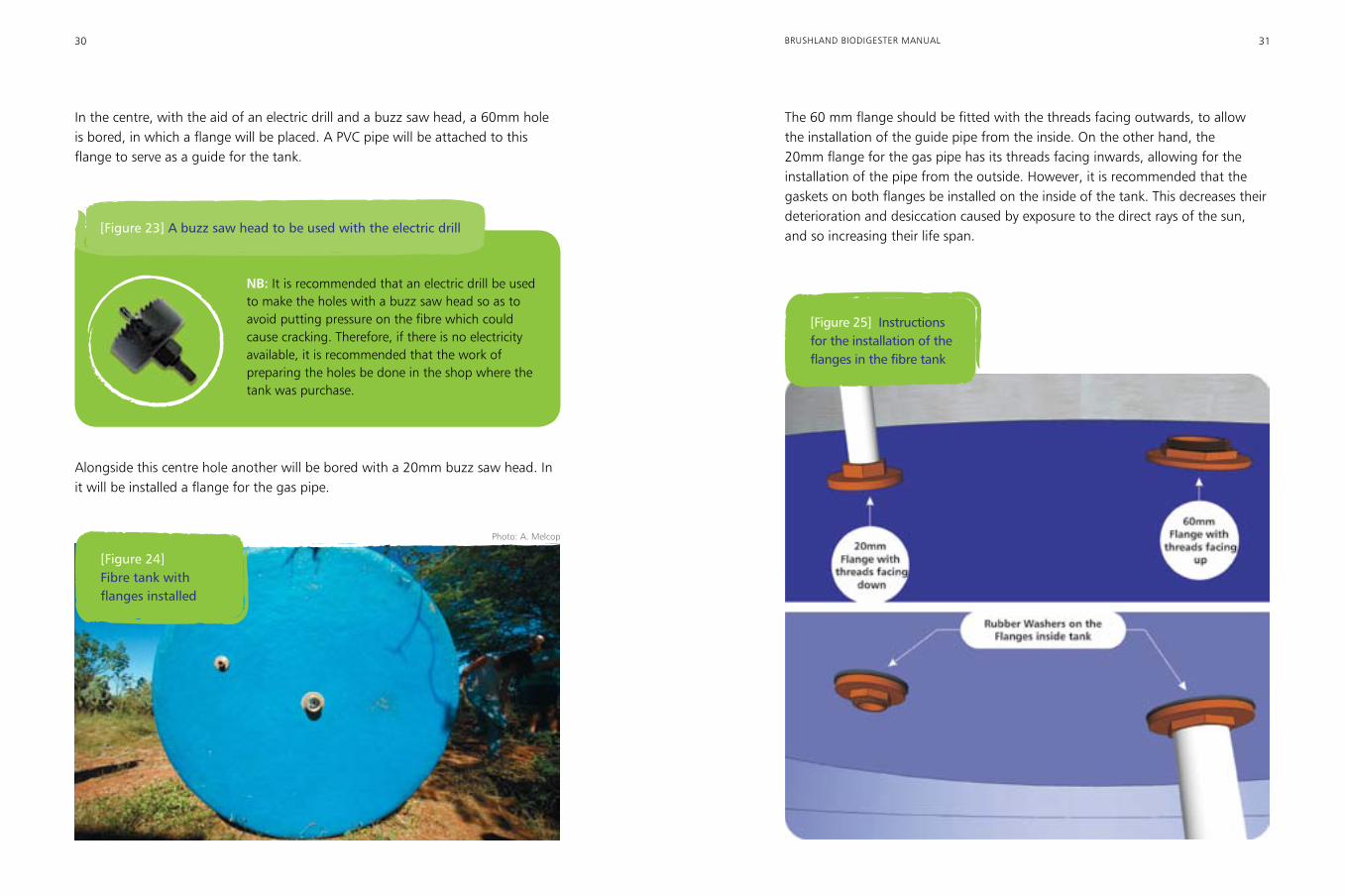
The preparation of the tank begins with the marking of the centre point on the bottom. The guide pipe will be installed at this mark, which will allow the fibre tank (combustion chamber) to rise and descend freely without scraping. Hence, it is essential that this point be in the dead centre. Otherwise, the biodigester will not function correctly.
1,52 m
1,32 m
2,06 m
[Figure 21] The fibre tank used here is one of 3,000 litres; the dimensions being those of the manufacturer
[Figure 22] Detail of the marking of the centre point on the bottom of fibre tank
Photo: A. Melcop Photos: A. Melcop
30 31BRUSHLAND BIODIGESTER MANUAL
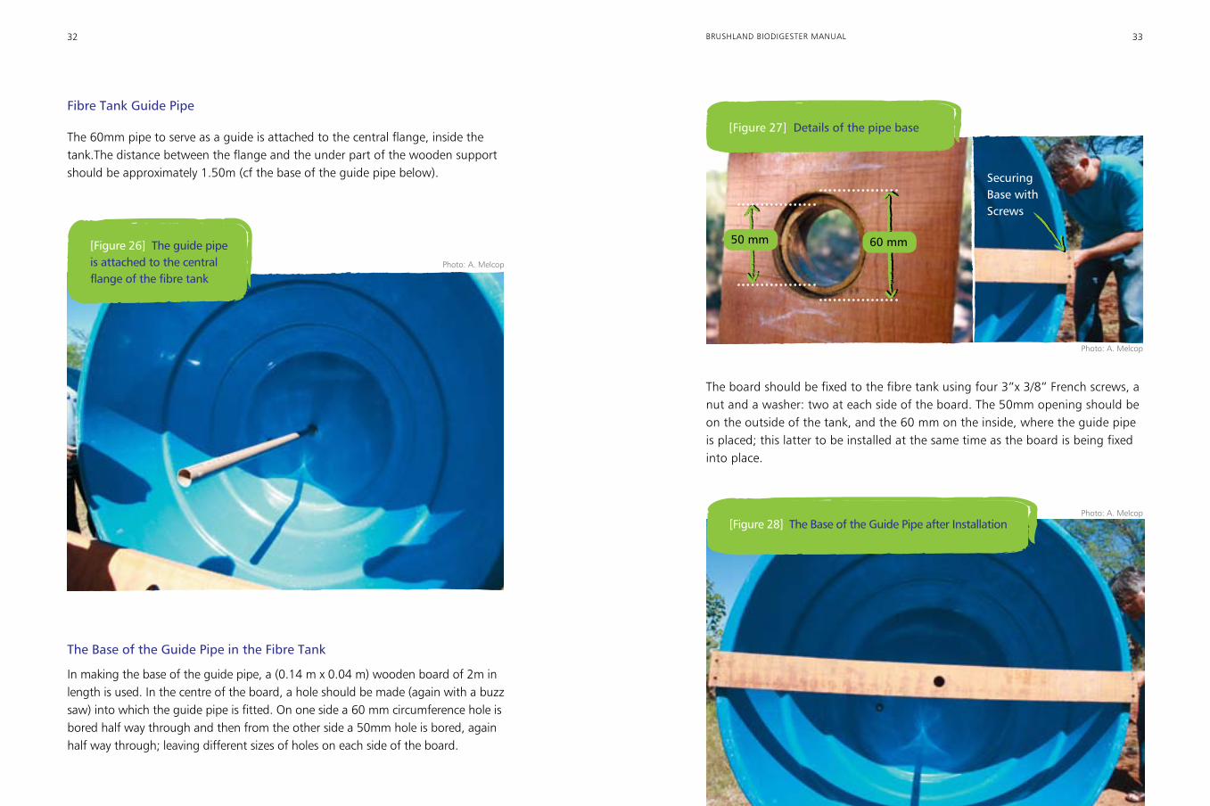
In the centre, with the aid of an electric drill and a buzz saw head, a 60mm hole is bored, in which a flange will be placed. A PVC pipe will be attached to this flange to serve as a guide for the tank.
The 60 mm flange should be fitted with the threads facing outwards, to allow the installation of the guide pipe from the inside. On the other hand, the 20mm flange for the gas pipe has its threads facing inwards, allowing for the installation of the pipe from the outside. However, it is recommended that the gaskets on both flanges be installed on the inside of the tank. This decreases their deterioration and desiccation caused by exposure to the direct rays of the sun, and so increasing their life span.
NB: It is recommended that an electric drill be used to make the holes with a buzz saw head so as to avoid putting pressure on the fibre which could cause cracking. Therefore, if there is no electricity available, it is recommended that the work of preparing the holes be done in the shop where the tank was purchase.
[Figure 23] A buzz saw head to be used with the electric drill
Alongside this centre hole another will be bored with a 20mm buzz saw head. In it will be installed a flange for the gas pipe.
[Figure 24] Fibre tank with flanges installed
[Figure 25] Instructions for the installation of the flanges in the fibre tank
Photo: A. Melcop
32 33BRUSHLAND BIODIGESTER MANUAL
Fibre Tank Guide Pipe
The 60mm pipe to serve as a guide is attached to the central flange, inside the tank.The distance between the flange and the under part of the wooden support should be approximately 1.50m (cf the base of the guide pipe below).
The board should be fixed to the fibre tank using four 3”x 3/8” French screws, a nut and a washer: two at each side of the board. The 50mm opening should be on the outside of the tank, and the 60 mm on the inside, where the guide pipe is placed; this latter to be installed at the same time as the board is being fixed into place.
The Base of the Guide Pipe in the Fibre Tank
In making the base of the guide pipe, a (0.14 m x 0.04 m) wooden board of 2m in length is used. In the centre of the board, a hole should be made (again with a buzz saw) into which the guide pipe is fitted. On one side a 60 mm circumference hole is bored half way through and then from the other side a 50mm hole is bored, again half way through; leaving different sizes of holes on each side of the board.
[Figure 27] Details of the pipe base
50 mm 60 mm
Securing Base with Screws
[Figure 28] The Base of the Guide Pipe after Installation
[Figure 26] The guide pipe is attached to the central flange of the fibre tank
Photo: A. Melcop
Photo: A. Melcop
Photo: A. Melcop
34 35BRUSHLAND BIODIGESTER MANUAL
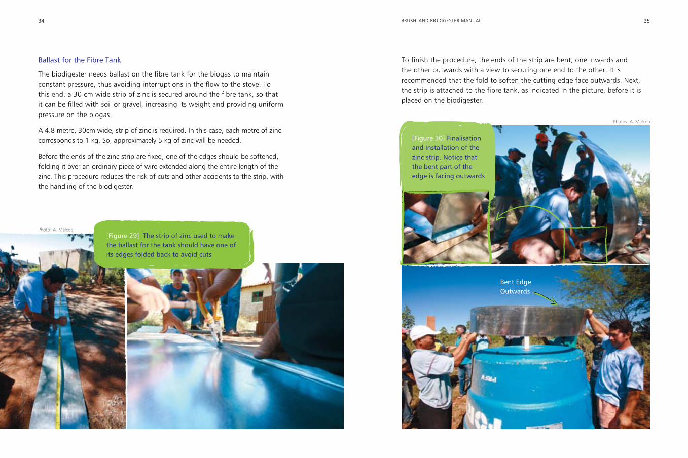
Ballast for the Fibre Tank
The biodigester needs ballast on the fibre tank for the biogas to maintain constant pressure, thus avoiding interruptions in the flow to the stove. To this end, a 30 cm wide strip of zinc is secured around the fibre tank, so that it can be filled with soil or gravel, increasing its weight and providing uniform pressure on the biogas.
A 4.8 metre, 30cm wide, strip of zinc is required. In this case, each metre of zinc corresponds to 1 kg. So, approximately 5 kg of zinc will be needed.
Before the ends of the zinc strip are fixed, one of the edges should be softened, folding it over an ordinary piece of wire extended along the entire length of the zinc. This procedure reduces the risk of cuts and other accidents to the strip, with the handling of the biodigester.
To finish the procedure, the ends of the strip are bent, one inwards and the other outwards with a view to securing one end to the other. It is recommended that the fold to soften the cutting edge face outwards. Next, the strip is attached to the fibre tank, as indicated in the picture, before it is placed on the biodigester.
[Figure 29] The strip of zinc used to make the ballast for the tank should have one of its edges folded back to avoid cuts
[Figure 30] Finalisation and installation of the zinc strip. Notice that the bent part of the edge is facing outwards
Bent Edge Outwards
Photo: A. Melcop
Photos: A. Melcop
36 37BRUSHLAND BIODIGESTER MANUAL
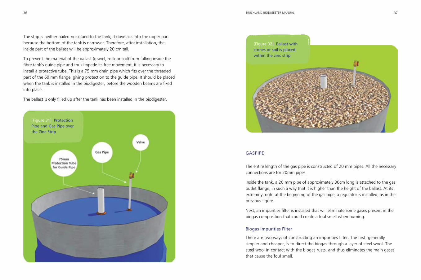
The strip is neither nailed nor glued to the tank; it dovetails into the upper part because the bottom of the tank is narrower. Therefore, after installation, the inside part of the ballast will be approximately 20 cm tall.
To prevent the material of the ballast (gravel, rock or soil) from falling inside the fibre tank’s guide pipe and thus impede its free movement, it is necessary to install a protective tube. This is a 75 mm drain pipe which fits over the threaded part of the 60 mm flange, giving protection to the guide pipe. It should be placed when the tank is installed in the biodigester, before the wooden beams are fixed into place.
The ballast is only filled up after the tank has been installed in the biodigester.
GASPIPE
The entire length of the gas pipe is constructed of 20 mm pipes. All the necessary connections are for 20mm pipes.
Inside the tank, a 20 mm pipe of approximately 30cm long is attached to the gas outlet flange, in such a way that it is higher than the height of the ballast. At its extremity, right at the beginning of the gas pipe, a regulator is installed; as in the previous figure.
Next, an impurities filter is installed that will eliminate some gases present in the biogas composition that could create a foul smell when burning.
Biogas Impurities Filter
There are two ways of constructing an impurities filter. The first, generally simpler and cheaper, is to direct the biogas through a layer of steel wool. The steel wool in contact with the biogas rusts, and thus eliminates the main gases that cause the foul smell.
[Figure 31] Protection Pipe and Gas Pipe over the Zinc Strip
[Figure 32] Ballast with stones or soil is placed within the zinc strip
38 39BRUSHLAND BIODIGESTER MANUAL
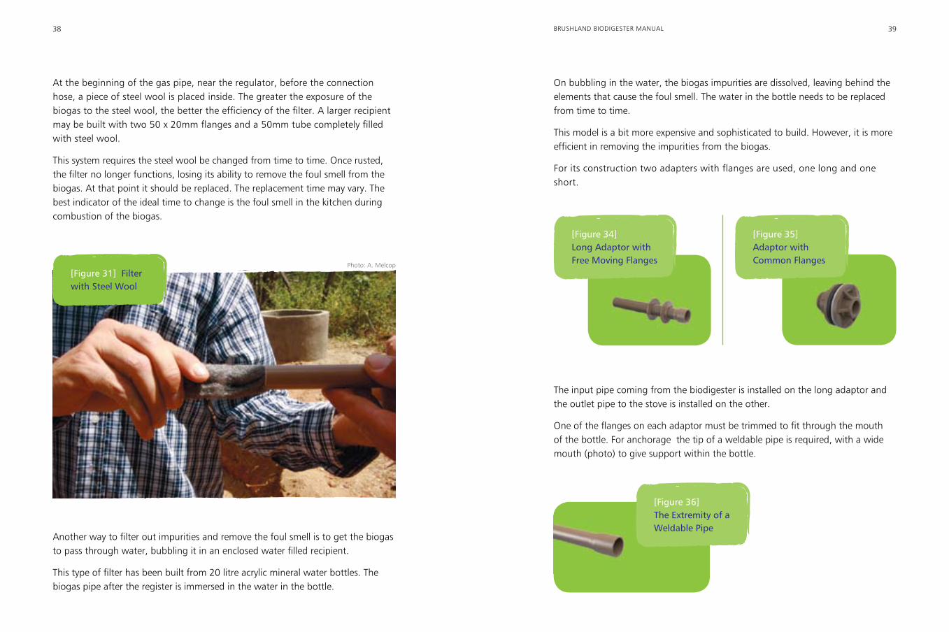
At the beginning of the gas pipe, near the regulator, before the connection hose, a piece of steel wool is placed inside. The greater the exposure of the biogas to the steel wool, the better the efficiency of the filter. A larger recipient may be built with two 50 x 20mm flanges and a 50mm tube completely filled with steel wool.
This system requires the steel wool be changed from time to time. Once rusted, the filter no longer functions, losing its ability to remove the foul smell from the biogas. At that point it should be replaced. The replacement time may vary. The best indicator of the ideal time to change is the foul smell in the kitchen during combustion of the biogas.
On bubbling in the water, the biogas impurities are dissolved, leaving behind the elements that cause the foul smell. The water in the bottle needs to be replaced from time to time.
This model is a bit more expensive and sophisticated to build. However, it is more efficient in removing the impurities from the biogas.
For its construction two adapters with flanges are used, one long and one short.
[Figure 31] Filter with Steel Wool
Another way to filter out impurities and remove the foul smell is to get the biogas to pass through water, bubbling it in an enclosed water filled recipient.
This type of filter has been built from 20 litre acrylic mineral water bottles. The biogas pipe after the register is immersed in the water in the bottle.
[Figure 34] Long Adaptor with Free Moving Flanges
[Figure 36] The Extremity of a Weldable Pipe
[Figure 35] Adaptor with Common Flanges
The input pipe coming from the biodigester is installed on the long adaptor and the outlet pipe to the stove is installed on the other.
One of the flanges on each adaptor must be trimmed to fit through the mouth of the bottle. For anchorage the tip of a weldable pipe is required, with a wide mouth (photo) to give support within the bottle.
Photo: A. Melcop
40 41BRUSHLAND BIODIGESTER MANUAL
The bottle is placed upside down and its neck sealed with a rubber plug, or a soft wooden cork. The bottle should contain water up to the level at which it touches the threaded part of the long adaptor.
To facilitate maintenance, we recommend the installation of a coupling near the regulator.
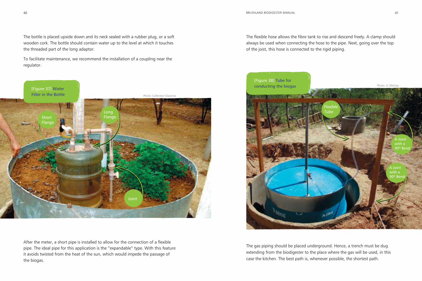
The flexible hose allows the fibre tank to rise and descend freely. A clamp should always be used when connecting the hose to the pipe. Next, going over the top of the joist, this hose is connected to the rigid piping.
Long Flange
After the meter, a short pipe is installed to allow for the connection of a flexible pipe. The ideal pipe for this application is the “expandable” type. With this feature it avoids twisted from the heat of the sun, which would impede the passage of the biogas.
[Figure 37] Water Filter in the Bottle
Short Flange
Joint
Flexible Tube
A Joint with a 90º Bend
[Figure 38] Tube for conducting the biogas
The gas piping should be placed underground. Hence, a trench must be dug extending from the biodigester to the place where the gas will be used, in this case the kitchen. The best path is, whenever possible, the shortest path.
Photo: Collection Diaconia
Photo: A. Melcop
A Joint with a 90º Bend
42 43BRUSHLAND BIODIGESTER MANUAL
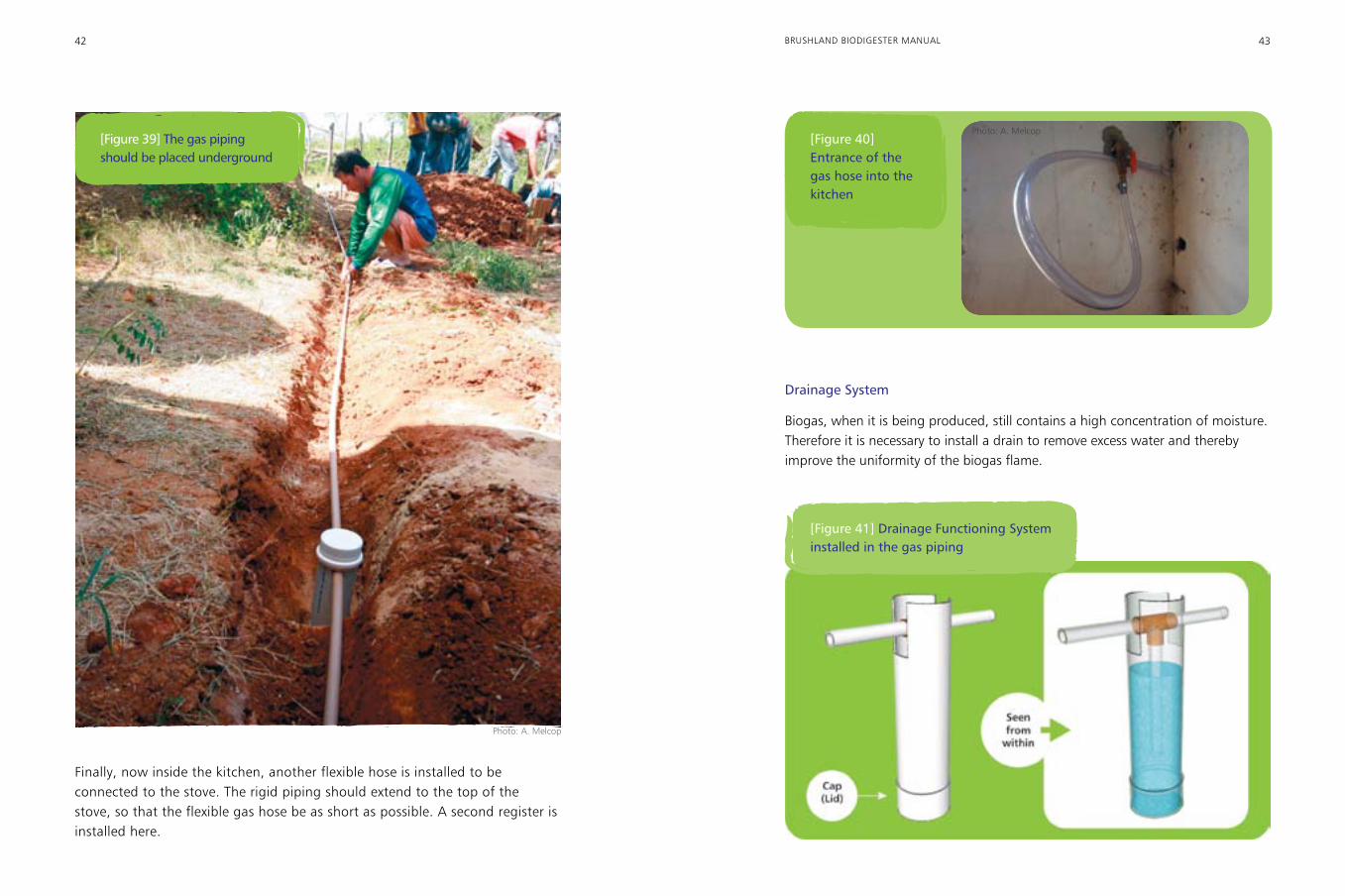
Finally, now inside the kitchen, another flexible hose is installed to be connected to the stove. The rigid piping should extend to the top of the stove, so that the flexible gas hose be as short as possible. A second register is installed here.
[Figure 39] The gas piping should be placed underground
[Figure 40] Entrance of the gas hose into the kitchen
Drainage System
Biogas, when it is being produced, still contains a high concentration of moisture. Therefore it is necessary to install a drain to remove excess water and thereby improve the uniformity of the biogas flame.
[Figure 41] Drainage Functioning System installed in the gas piping
Photo: A. Melcop
Photo: A. Melcop
44 45BRUSHLAND BIODIGESTER MANUAL
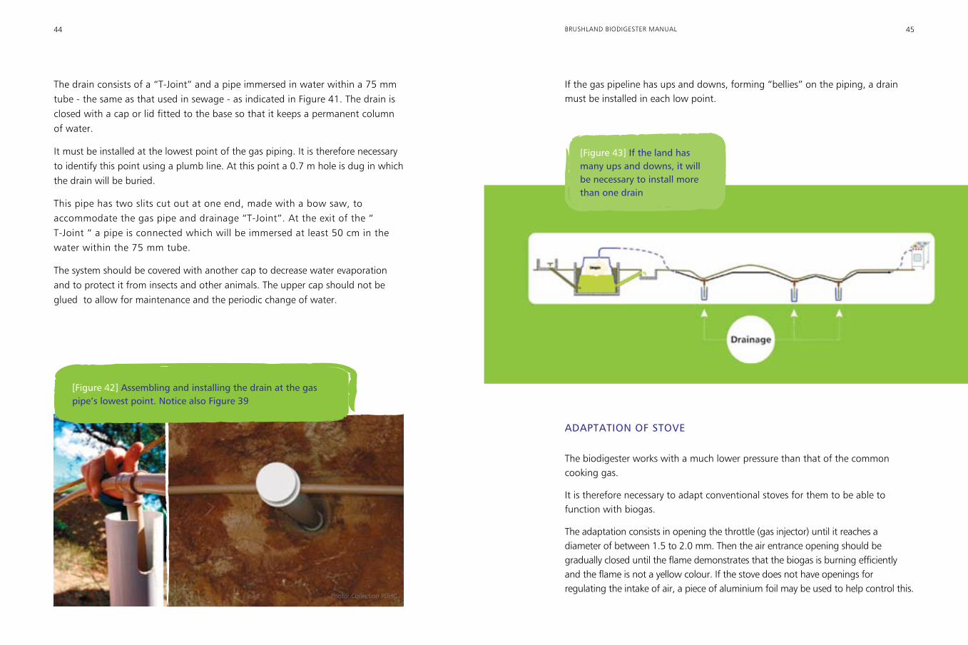
The drain consists of a “T-Joint” and a pipe immersed in water within a 75 mm tube - the same as that used in sewage - as indicated in Figure 41. The drain is closed with a cap or lid fitted to the base so that it keeps a permanent column of water.
It must be installed at the lowest point of the gas piping. It is therefore necessary to identify this point using a plumb line. At this point a 0.7 m hole is dug in which the drain will be buried.
This pipe has two slits cut out at one end, made with a bow saw, to accommodate the gas pipe and drainage “T-Joint”. At the exit of the “ T-Joint “ a pipe is connected which will be immersed at least 50 cm in the water within the 75 mm tube.
The system should be covered with another cap to decrease water evaporation and to protect it from insects and other animals. The upper cap should not be glued to allow for maintenance and the periodic change of water.
If the gas pipeline has ups and downs, forming “bellies” on the piping, a drain must be installed in each low point.
[Figure 42] Assembling and installing the drain at the gas pipe’s lowest point. Notice also Figure 39
[Figure 43] If the land has many ups and downs, it will be necessary to install more than one drain
ADAPTATION OF STOVE
The biodigester works with a much lower pressure than that of the common cooking gas.
It is therefore necessary to adapt conventional stoves for them to be able to function with biogas.
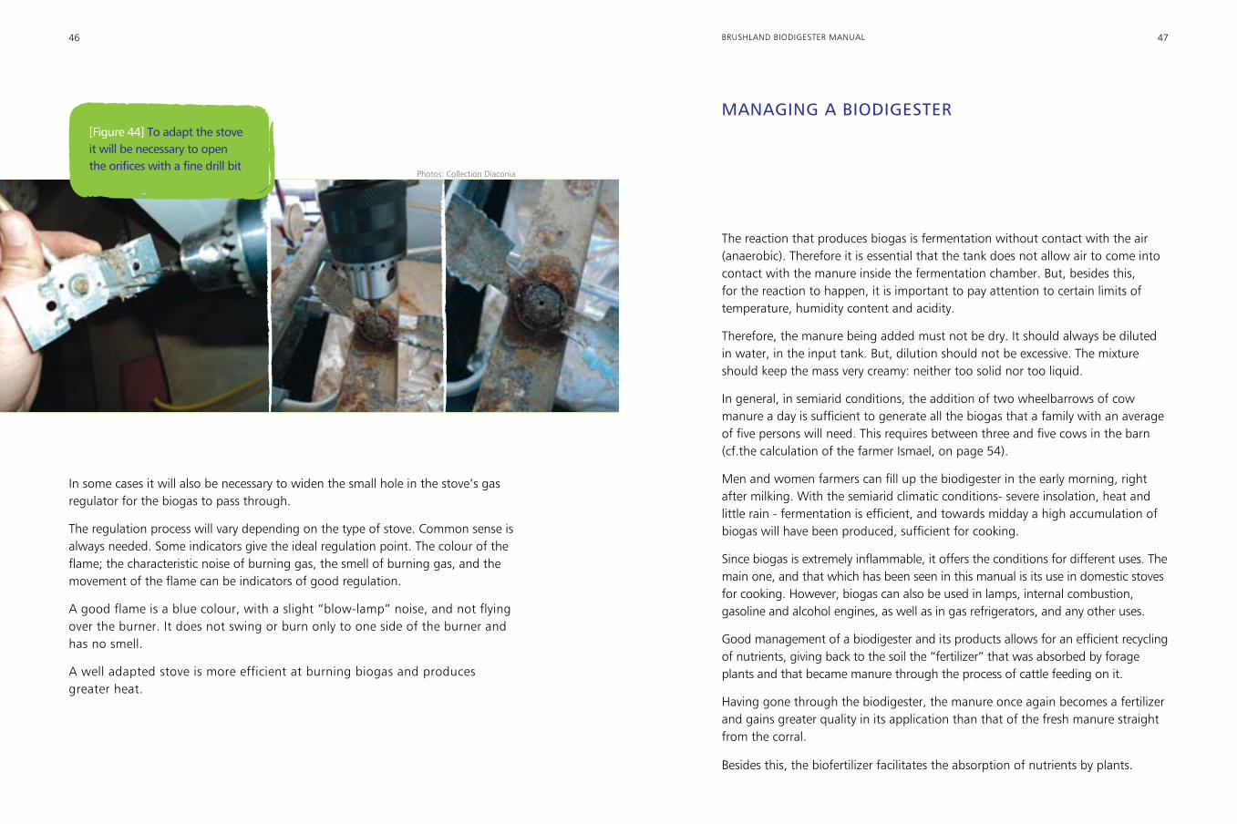
The adaptation consists in opening the throttle (gas injector) until it reaches a diameter of between 1.5 to 2.0 mm. Then the air entrance opening should be gradually closed until the flame demonstrates that the biogas is burning efficiently and the flame is not a yellow colour. If the stove does not have openings for regulating the intake of air, a piece of aluminium foil may be used to help control this.
Photo: Collection PDHC
46 47BRUSHLAND BIODIGESTER MANUAL
In some cases it will also be necessary to widen the small hole in the stove’s gas regulator for the biogas to pass through.
The regulation process will vary depending on the type of stove. Common sense is always needed. Some indicators give the ideal regulation point. The colour of the flame; the characteristic noise of burning gas, the smell of burning gas, and the movement of the flame can be indicators of good regulation.
A good flame is a blue colour, with a slight “blow-lamp” noise, and not flying over the burner. It does not swing or burn only to one side of the burner and has no smell.
A well adapted stove is more efficient at burning biogas and produces greater heat.
[Figure 44] To adapt the stove it will be necessary to open the orifices with a fine drill bit
MANAGING A BIODIGESTER
The reaction that produces biogas is fermentation without contact with the air (anaerobic). Therefore it is essential that the tank does not allow air to come into contact with the manure inside the fermentation chamber. But, besides this, for the reaction to happen, it is important to pay attention to certain limits of temperature, humidity content and acidity.
Therefore, the manure being added must not be dry. It should always be diluted in water, in the input tank. But, dilution should not be excessive. The mixture should keep the mass very creamy: neither too solid nor too liquid.
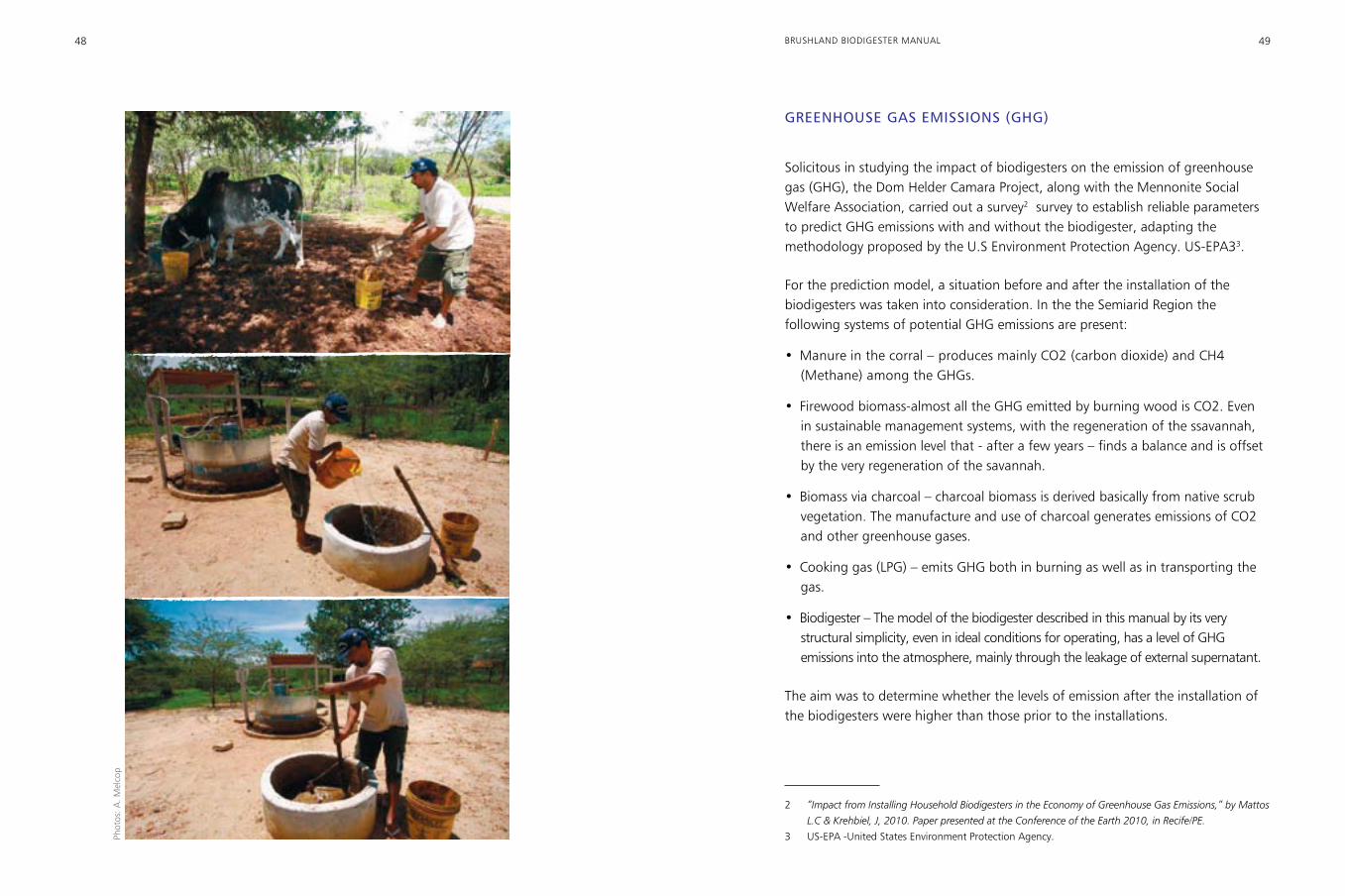
In general, in semiarid conditions, the addition of two wheelbarrows of cow manure a day is sufficient to generate all the biogas that a family with an average of five persons will need. This requires between three and five cows in the barn (cf.the calculation of the farmer Ismael, on page 54).
Men and women farmers can fill up the biodigester in the early morning, right after milking. With the semiarid climatic conditions- severe insolation, heat and little rain - fermentation is efficient, and towards midday a high accumulation of biogas will have been produced, sufficient for cooking.
Since biogas is extremely inflammable, it offers the conditions for different uses. The main one, and that which has been seen in this manual is its use in domestic stoves for cooking. However, biogas can also be used in lamps, internal combustion, gasoline and alcohol engines, as well as in gas refrigerators, and any other uses.
Good management of a biodigester and its products allows for an efficient recycling of nutrients, giving back to the soil the “fertilizer” that was absorbed by forage plants and that became manure through the process of cattle feeding on it.
Having gone through the biodigester, the manure once again becomes a fertilizer and gains greater quality in its application than that of the fresh manure straight from the corral.
Besides this, the biofertilizer facilitates the absorption of nutrients by plants.
Photos: Collection Diaconia
48 49BRUSHLAND BIODIGESTER MANUAL
GREENHOUSE GAS EMISSIONS (GHG)
Solicitous in studying the impact of biodigesters on the emission of greenhouse gas (GHG), the Dom Helder Camara Project, along with the Mennonite Social Welfare Association, carried out a survey2 survey to establish reliable parameters to predict GHG emissions with and without the biodigester, adapting the methodology proposed by the U.S Environment Protection Agency. US-EPA33.
For the prediction model, a situation before and after the installation of the biodigesters was taken into consideration. In the the Semiarid Region the following systems of potential GHG emissions are present:
•Manure in the corral – produces mainly CO2 (carbon dioxide) and CH4 (Methane) among the GHGs.
• Firewood biomass-almost all the GHG emitted by burning wood is CO2. Even in sustainable management systems, with the regeneration of the ssavannah, there is an emission level that - after a few years – finds a balance and is offset by the very regeneration of the savannah.
• Biomass via charcoal – charcoal biomass is derived basically from native scrub vegetation. The manufacture and use of charcoal generates emissions of CO2 and other greenhouse gases.
• Cooking gas (LPG) – emits GHG both in burning as well as in transporting the gas.
• Biodigester – The model of the biodigester described in this manual by its very structural simplicity, even in ideal conditions for operating, has a level of GHG emissions into the atmosphere, mainly through the leakage of external supernatant.
The aim was to determine whether the levels of emission after the installation of the biodigesters were higher than those prior to the installations.
2 “Impact from Installing Household Biodigesters in the Economy of Greenhouse Gas Emissions,” by Mattos
L.C & Krehbiel, J, 2010. Paper presented at the Conference of the Earth 2010, in Recife/PE.
3 US-EPA -United States Environment Protection Agency.Phot
os: A
. Mel
cop
50 51BRUSHLAND BIODIGESTER MANUAL
Studies have indicated that the impact of biodigesters is globally positive. With the use of biodigesters, the global emission of greenhouse gases is reduced, because GHGs are no longer emitted due to the use of firewood, charcoal and LPG.
What’s more, a part of corral manure is used in the production of biogas. The biodigester also produces other environmental benefits such as fertilizers that will promote a more efficient recycling of nutrients in agriculture and livestock rearing.
In addition to environmental benefits, as an alternative to deforestation from getting firewood and charcoal as well as by reducing GHG; agricultural families are recording health benefits with the elimination of smoke from the wood burning in the stove. They are also able to save time with less work to do in fetching firewood, not always located near the house.
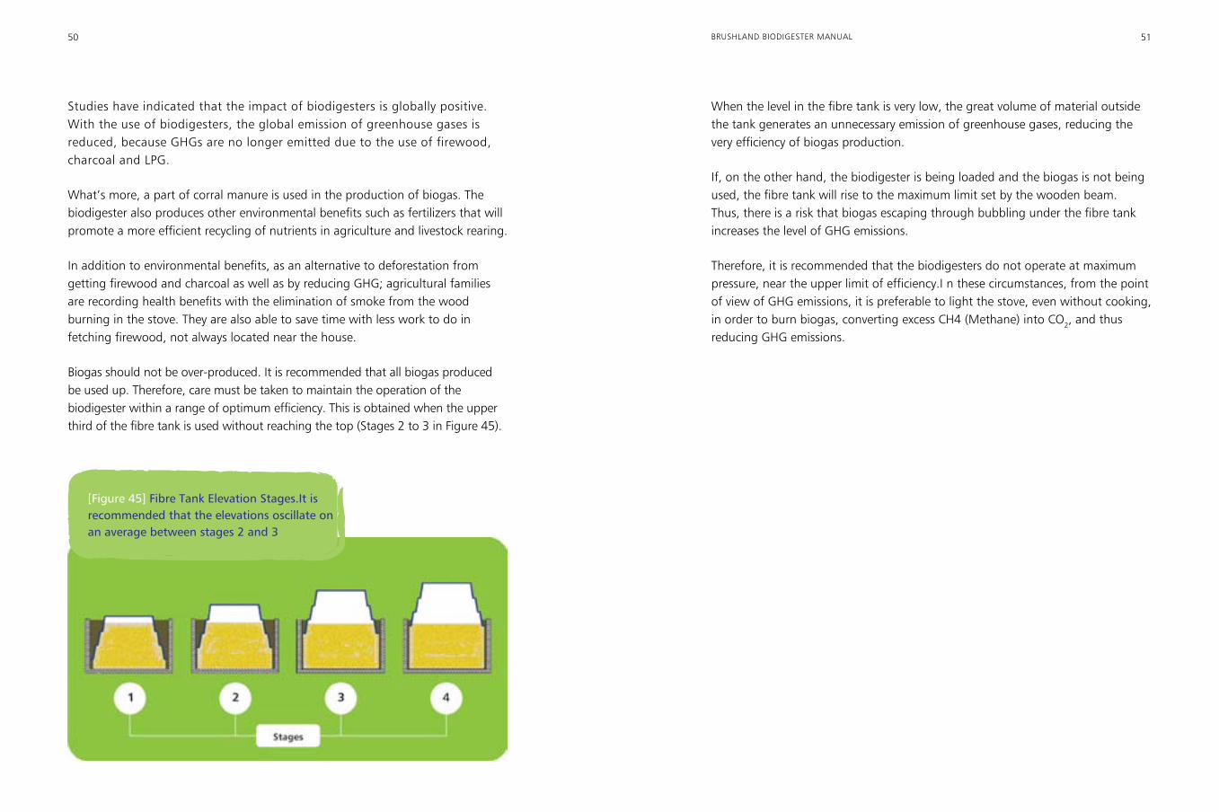
Biogas should not be over-produced. It is recommended that all biogas produced be used up. Therefore, care must be taken to maintain the operation of the biodigester within a range of optimum efficiency. This is obtained when the upper third of the fibre tank is used without reaching the top (Stages 2 to 3 in Figure 45).
When the level in the fibre tank is very low, the great volume of material outside the tank generates an unnecessary emission of greenhouse gases, reducing the very efficiency of biogas production.
If, on the other hand, the biodigester is being loaded and the biogas is not being used, the fibre tank will rise to the maximum limit set by the wooden beam. Thus, there is a risk that biogas escaping through bubbling under the fibre tank increases the level of GHG emissions.
Therefore, it is recommended that the biodigesters do not operate at maximum pressure, near the upper limit of efficiency.I n these circumstances, from the point of view of GHG emissions, it is preferable to light the stove, even without cooking, in order to burn biogas, converting excess CH4 (Methane) into CO2, and thus reducing GHG emissions.
[Figure 45] Fibre Tank Elevation Stages.It is recommended that the elevations oscillate on an average between stages 2 and 3
52 53BRUSHLAND BIODIGESTER MANUAL
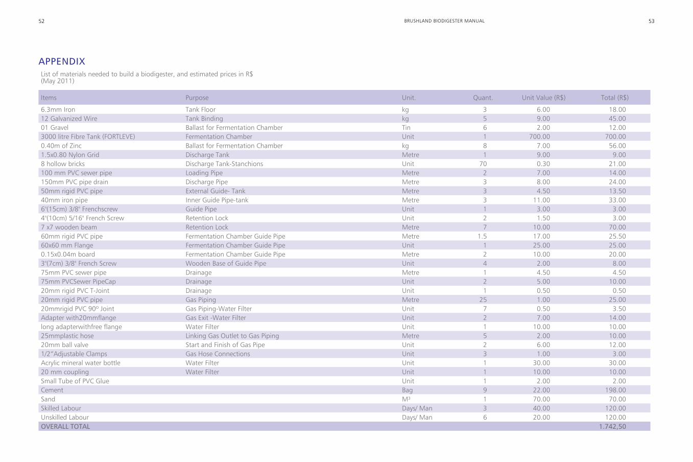
APPENDIXList of materials needed to build a biodigester, and estimated prices in R$ (May 2011)
Items Purpose Unit. Quant. Unit Value (R$) Total (R$)
6.3mm Iron Tank Floor kg 3 6.00 18.00 12 Galvanized Wire Tank Binding kg 5 9.00 45.00 01 Gravel Ballast for Fermentation Chamber Tin 6 2.00 12.003000 litre Fibre Tank (FORTLEVE) Fermentation Chamber Unit 1 700.00 700.000.40m of Zinc Ballast for Fermentation Chamber kg 8 7.00 56.00 1.5x0.80 Nylon Grid Discharge Tank Metre 1 9.00 9.008 hollow bricks Discharge Tank-Stanchions Unit 70 0.30 21.00 100 mm PVC sewer pipe Loading Pipe Metre 2 7.00 14.00150mm PVC pipe drain Discharge Pipe Metre 3 8.00 24.0050mm rigid PVC pipe External Guide- Tank Metre 3 4.50 13.5040mm iron pipe Inner Guide Pipe-tank Metre 3 11.00 33.006"(15cm) 3/8" Frenchscrew Guide Pipe Unit 1 3.00 3.004"(10cm) 5/16" French Screw Retention Lock Unit 2 1.50 3.007 x7 wooden beam Retention Lock Metre 7 10.00 70.0060mm rigid PVC pipe Fermentation Chamber Guide Pipe Metre 1.5 17.00 25.5060x60 mm Flange Fermentation Chamber Guide Pipe Unit 1 25.00 25.000.15x0.04m board Fermentation Chamber Guide Pipe Metre 2 10.00 20.003"(7cm) 3/8" French Screw Wooden Base of Guide Pipe Unit 4 2.00 8.00 75mm PVC sewer pipe Drainage Metre 1 4.50 4.5075mm PVCSewer PipeCap Drainage Unit 2 5.00 10.0020mm rigid PVC T-Joint Drainage Unit 1 0.50 0.5020mm rigid PVC pipe Gas Piping Metre 25 1.00 25.0020mmrigid PVC 90º Joint Gas Piping-Water Filter Unit 7 0.50 3.50 Adapter with20mmflange Gas Exit -Water Filter Unit 2 7.00 14.00long adapterwithfree flange Water Filter Unit 1 10.00 10.0025mmplastic hose Linking Gas Outlet to Gas Piping Metre 5 2.00 10.0020mm ball valve Start and Finish of Gas Pipe Unit 2 6.00 12.001/2“Adjustable Clamps Gas Hose Connections Unit 3 1.00 3.00Acrylic mineral water bottle Water Filter Unit 1 30.00 30.0020 mm coupling Water Filter Unit 1 10.00 10.00Small Tube of PVC Glue Unit 1 2.00 2.00Cement Bag 9 22.00 198.00Sand M³ 1 70.00 70.00Skilled Labour Days/ Man 3 40.00 120.00Unskilled Labour Days/ Man 6 20.00 120.00OVERALL TOTAL 1.742,50
54 55BRUSHLAND BIODIGESTER MANUAL
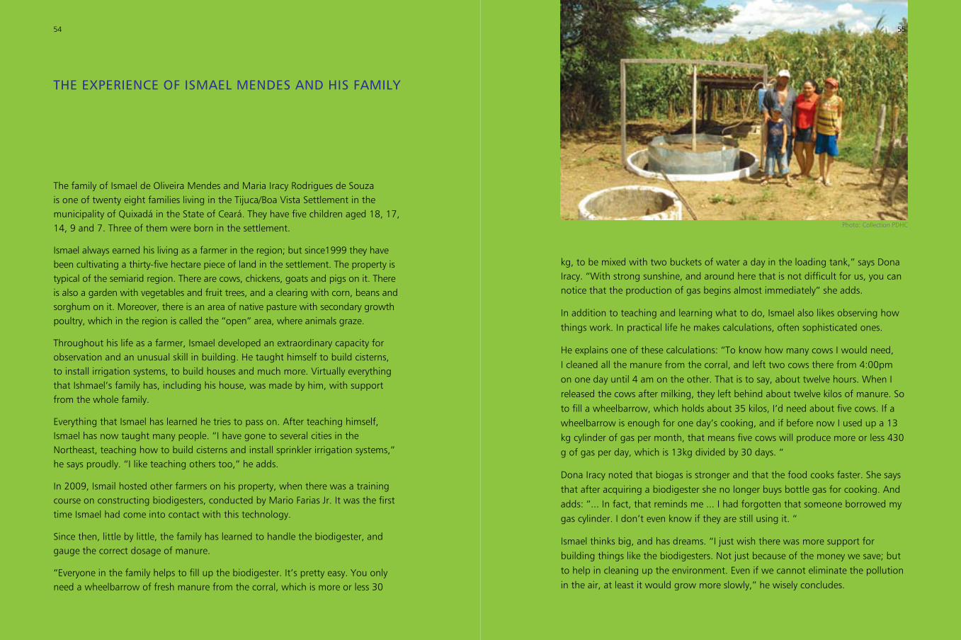
THE EXPERIENCE OF ISMAEL MENDES AND HIS FAMILy
The family of Ismael de Oliveira Mendes and Maria Iracy Rodrigues de Souza is one of twenty eight families living in the Tijuca/Boa Vista Settlement in the municipality of Quixadá in the State of Ceará. They have five children aged 18, 17, 14, 9 and 7. Three of them were born in the settlement.
Ismael always earned his living as a farmer in the region; but since1999 they have been cultivating a thirty-five hectare piece of land in the settlement. The property is typical of the semiarid region. There are cows, chickens, goats and pigs on it. There is also a garden with vegetables and fruit trees, and a clearing with corn, beans and sorghum on it. Moreover, there is an area of native pasture with secondary growth poultry, which in the region is called the “open” area, where animals graze.
Throughout his life as a farmer, Ismael developed an extraordinary capacity for observation and an unusual skill in building. He taught himself to build cisterns, to install irrigation systems, to build houses and much more. Virtually everything that Ishmael’s family has, including his house, was made by him, with support from the whole family.
Everything that Ismael has learned he tries to pass on. After teaching himself, Ismael has now taught many people. “I have gone to several cities in the Northeast, teaching how to build cisterns and install sprinkler irrigation systems,” he says proudly. “I like teaching others too,” he adds.
In 2009, Ismail hosted other farmers on his property, when there was a training course on constructing biodigesters, conducted by Mario Farias Jr. It was the first time Ismael had come into contact with this technology.
Since then, little by little, the family has learned to handle the biodigester, and gauge the correct dosage of manure.
“Everyone in the family helps to fill up the biodigester. It’s pretty easy. You only need a wheelbarrow of fresh manure from the corral, which is more or less 30
kg, to be mixed with two buckets of water a day in the loading tank,” says Dona Iracy. “With strong sunshine, and around here that is not difficult for us, you can notice that the production of gas begins almost immediately” she adds.
In addition to teaching and learning what to do, Ismael also likes observing how things work. In practical life he makes calculations, often sophisticated ones.
He explains one of these calculations: “To know how many cows I would need, I cleaned all the manure from the corral, and left two cows there from 4:00pm on one day until 4 am on the other. That is to say, about twelve hours. When I released the cows after milking, they left behind about twelve kilos of manure. So to fill a wheelbarrow, which holds about 35 kilos, I’d need about five cows. If a wheelbarrow is enough for one day’s cooking, and if before now I used up a 13 kg cylinder of gas per month, that means five cows will produce more or less 430 g of gas per day, which is 13kg divided by 30 days. “
Dona Iracy noted that biogas is stronger and that the food cooks faster. She says that after acquiring a biodigester she no longer buys bottle gas for cooking. And adds: “... In fact, that reminds me ... I had forgotten that someone borrowed my gas cylinder. I don’t even know if they are still using it. “
Ismael thinks big, and has dreams. “I just wish there was more support for building things like the biodigesters. Not just because of the money we save; but to help in cleaning up the environment. Even if we cannot eliminate the pollution in the air, at least it would grow more slowly,” he wisely concludes.
54
Photo: Collection PDHC
55