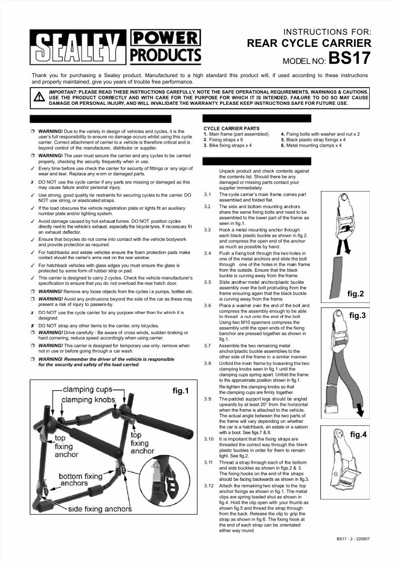
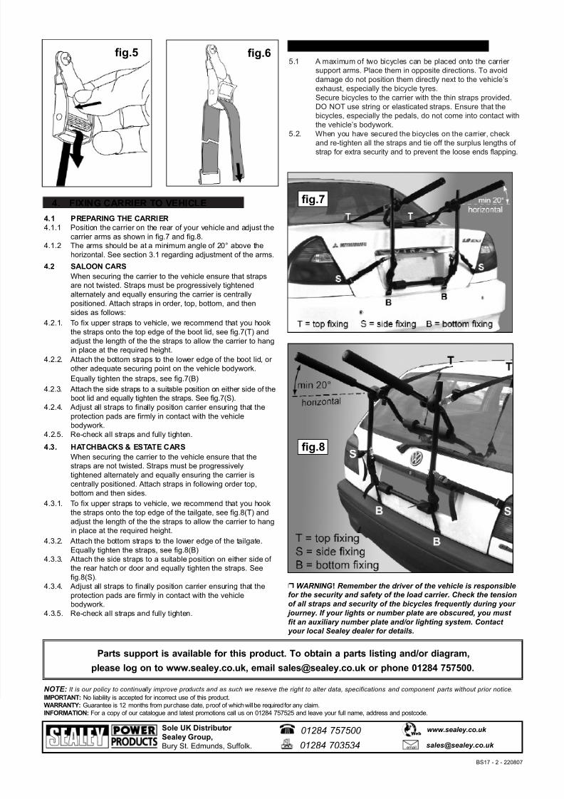
INSTRUCTIONS FOR: REAR CYCLE CARRIER MOD EL NO: BS17 Thank you for purchasing a Sealey product. Manufactured to a high standard this product will, if used according to these instructions and properly maintained, give you years of trouble free performance. BS17 - 2 - 220807 1. SAFETY INSTR UCTIONS 2. CONTENTS 3. CARRIER ASSEMBL Y CYCLE CARRIER PARTS 1. Main frame (part assembled) 4. Fixing bolts with washer and nut x 2 2. Fixing straps x 6 5. Black plastic strap fixings x 4 3. Bike fixing straps x 4 6. Metal mounting clamps x 4 ! WARNING! Due to the variety in design of vehicles and cycles, it is the user’s full responsibility to ensure no damage occurs whilst using this cycle carrier. Correct attachment of carrier to a vehicle is therefore critical and is beyond control of the manufacturer, distributor or supplier. ! WARNING! The user must secure the carrier and any cycles to be carried properly, checking the security frequently when in use. # Every time before use check the carrier for security of fittings or any sign ofwear and tear. Replace any w orn or damaged parts. $ DO NOT use the cycle carrier if any part s are missing or damaged as this may cause failure and/or personal injury. # Use strong, good quality tie restraints for securing cycles to the carrier . DO NOT use string, or elasticated straps. # If the load obscures the vehicle registration plate or lights fit an auxiliary number plate and/or lighting system. # Avoid damage caused by hot exhaus t fumes. DO NOT position cycl es directly next to the vehicle’s exha ust, especially the bicycle tyres. If necessary fi t an exhaust deflector. # Ensure that bicycles do not come into contact with the vehicle bodywork and provide protection as required. # For hatchbacks and estate vehicles ensure the foam protection pads make contact should the carrier’s arms rest on the rear window. # For hatchback vehicles with glass edges you must ensure the glass is protected by some form of rubber strip or pad. # This carrier is designed to carry 2 cycles. Check the vehicle manufacturer’s specification to ensure that you do not overload the rear hatch door. % WARNING!Remove any loose objects from the cycles i.e pumps, bottles etc. % WARNING!Avoid any protrusions beyond the side of the car as these may present a risk of injury to passers-by. $ DO NOT use the cycle carrier for any purpo se other than for which it is designed. & DO NOT strap any other items to the carrier , only bicycles. % WARNING!Drive carefully - Be aware of cross winds, sudden braking orhard cornering, reduce speed accordingly when using carrier. % WARNING!This carrier is designed for temporary use only, remove when not in use or before going through a car wash. % WARNING! Remember the driver of the vehicle is responsible for the security and safety of the load carried. IMPORTANT: PLEASE READ THESE INSTRUCTIONS CAREFUL LY . NOTE THE SAFE OPERATIONAL REQUIREMENTS, WARNINGS & CAUTIONS. USE THE PRODUCT CORRECTL Y AND WITH CARE FOR THE PURPOSE FOR WHICH IT IS INTENDED. FAI LURE TO DO SO MAY CAUSE DAMAGE OR PERSONAL INJUR Y , AND WILL INVALIDA TE THE WARRANTY . PLEASE KEEP INSTRUCT IONS SAFE FOR FUTURE USE. fig.1 Unpack product and check contents against the contents list. Should there be any damaged or missing parts contact yoursupplier immediately . 3.1 The cyc le car rier’s mai n f rame co mes part assembled and folded flat. 3. 2 The si de and bot tom mounti ng anchors share the same fixing bolts and need to be assembled to the lower part of the frame as seen in fig.1. 3. 3 Hook a metal mount ing anchor t hr ough each black plastic buckle as shown in fig.2. and compress the open end of the anchoras much as possible by hand. 3.4 Push a fix ing bolt through the two holes in one of the metal anchors and slide the bolt through one of the holes in the ma in frame from the outside. Ensure that the black buckle is curving away from the frame. 3.5 Slide a not her met al a nchor/plastic buckle assembly over the bolt protruding from the frame ensuring again that the black buckle is curving away from the frame. 3.6 Place a wa sher over the end of the bolt and compress the assembly enough to be able to thread a nut onto the end o f the bolt. Using two M10 spanners compress the assembly until the open ends of the fixing banchor are pressed together as shown in fig.1. 3.7 Assemble the two remaining metal anchor/plastic buckle assemblies to the other side of the frame in a similar manner. 3.8 Unf old the mai n fr ame by loo sen ing the two clamping knobs seen in fig.1 until the clamping cups spring apart. Unfold the frame to the approximate position shown in fig.1. Re-tighten the clamping knobs so that the clamping cups are firmly together . 3.9 The padde d supp ort leg s shou ld b e an gle d upwards by at least 20° from the horizontal when the frame is attached to the vehicle. The actual angle between the two parts ofthe frame will vary depending on whetherthe car is a hatchback, an estate or a saloon with a boot. See figs.7 & 8. 3.10 It is impor tant that the fixing straps are threaded the correct way through the black plastic buckles in order for them to remain tight. See fig.2. 3.11 Thread a strap through each of t he bottom and side buckles as shown in figs.2 & 3. The fixing hooks on the end of the straps should be facing backwards as shown in fig.3. 3.12 Attac h t he remai ning two strap s to the top anchor fixings as shown in fig.1. The metal clips are spring loaded shut as shown in fig.4. Hold the clip open with your thumb as shown fig.5 and thread the strap through from the back. Release the clip to grip the strap as shown in fig.6. The fixing hook at the end of each strap can be orientated either way round. fig.2 fig.3 fig.4