Embed Size (px)
Citation preview
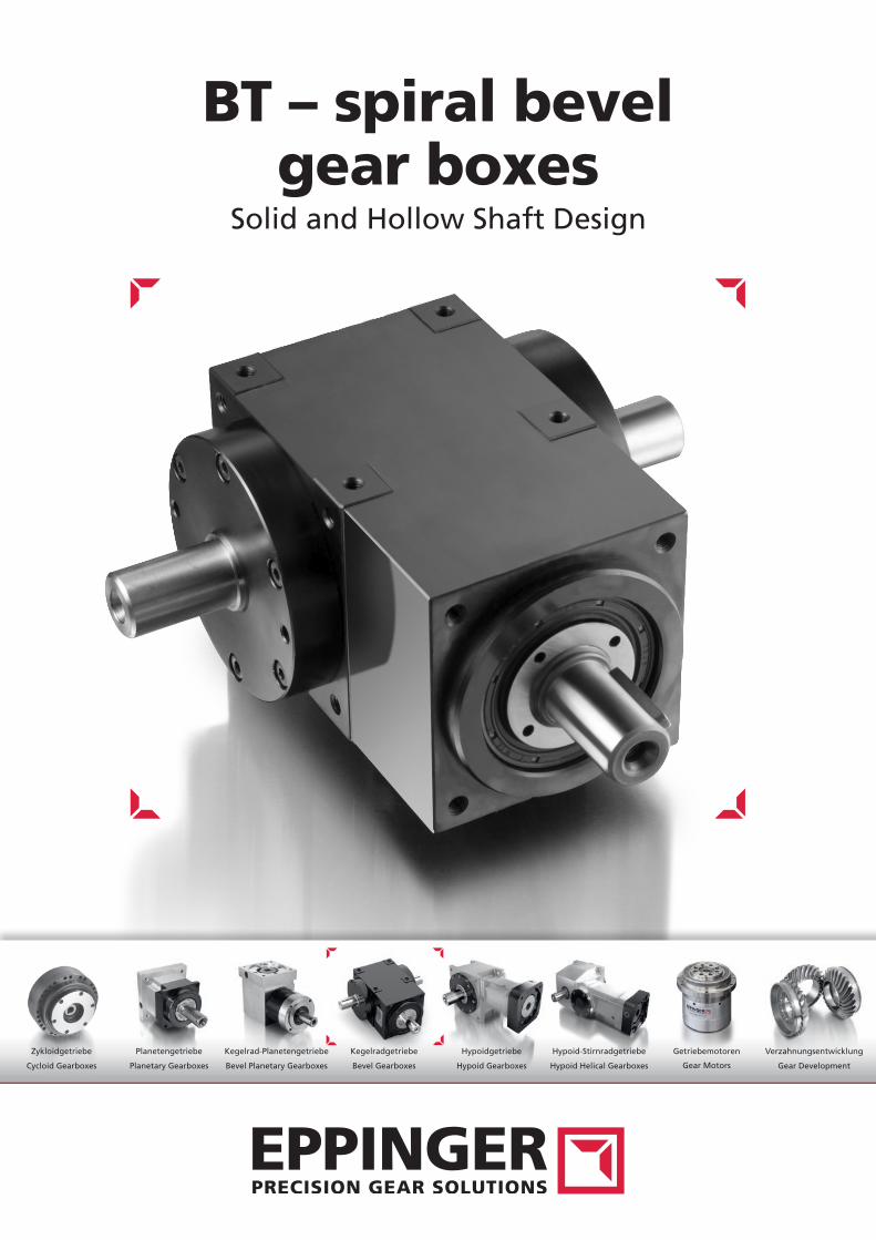
BT – spiral bevel gear boxes
Solid and Hollow Shaft Design
Zykloidgetriebe Planetengetriebe Kegelradgetriebe Hypoidgetriebe Hypoid-StirnradgetriebeKegelrad-Planetengetriebe Getriebemotoren Verzahnungsentwicklung
Cycloid Gearboxes Planetary Gearboxes Bevel Gearboxes Hypoid Gearboxes Hypoid Helical GearboxesBevel Planetary Gearboxes Gear Motors Gear Development
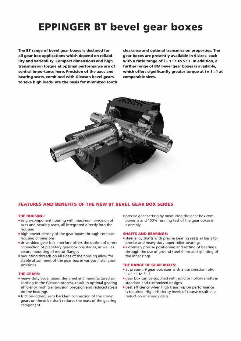
THE HOUSING: single-component housing with maximum precision of axes and bearing seats, all integrated directly into the housing high power density of the gear boxes through compact housing dimensions drive-sided gear box interface offers the option of direct connection of planetary gear box pre-stages, as well as secure mounting of motor flanges mounting threads on all sides of the housing allow for stable attachment of the gear box in various installation positions
THE GEARS: heavy duty bevel gears, designed and manufactured ac-cording to the Gleason process, result in optimal gearing efficiency, high transmission precision and reduced stress on the bearings friction-locked, zero backlash connection of the crown gears on the drive shaft reduces the mass of the gearing component
precise gear setting by measuring the gear box com-ponents and 100% running test of the gear boxes in assembly
SHAFTS AND BEARINGS: steel alloy shafts with precise bearing seats as basis for precise and heavy duty taper roller bearings
extremely precise positioning and setting of bearings through the use of ground steel shims and splinting of the inner rings
THE RANGE OF GEAR BOXES: at present, 9 gear box sizes with a transmission ratio
i = 1 : 1 to 5 : 1 gear box can be supplied with solid or hollow shafts in
standard and customized designs best efficiency when high transmission performance is required. High efficiency levels of course result in a reduction of energy costs.
FEATURES AND BENEFITS OF THE NEW BT BEVEL GEAR BOX SERIES
The BT range of bevel gear boxes is destined for all gear box applications which depend on reliabi-lity and variability. Compact dimensions and high transmission torque at optimal performance are of central importance here. Precision of the axes and bearing seats, combined with Gleason bevel gears to take high loads, are the basis for minmized tooth
clearance and optimal transmission properties. The gear boxes are presently available in 9 sizes, each with a ratio range of i = 1 : 1 to 5 : 1. In addition, a further range of BM bevel gear boxes is available, which offers significantly greater torque at i = 1 : 1 at comparable sizes.
EPPINGER BT bevel gear boxes
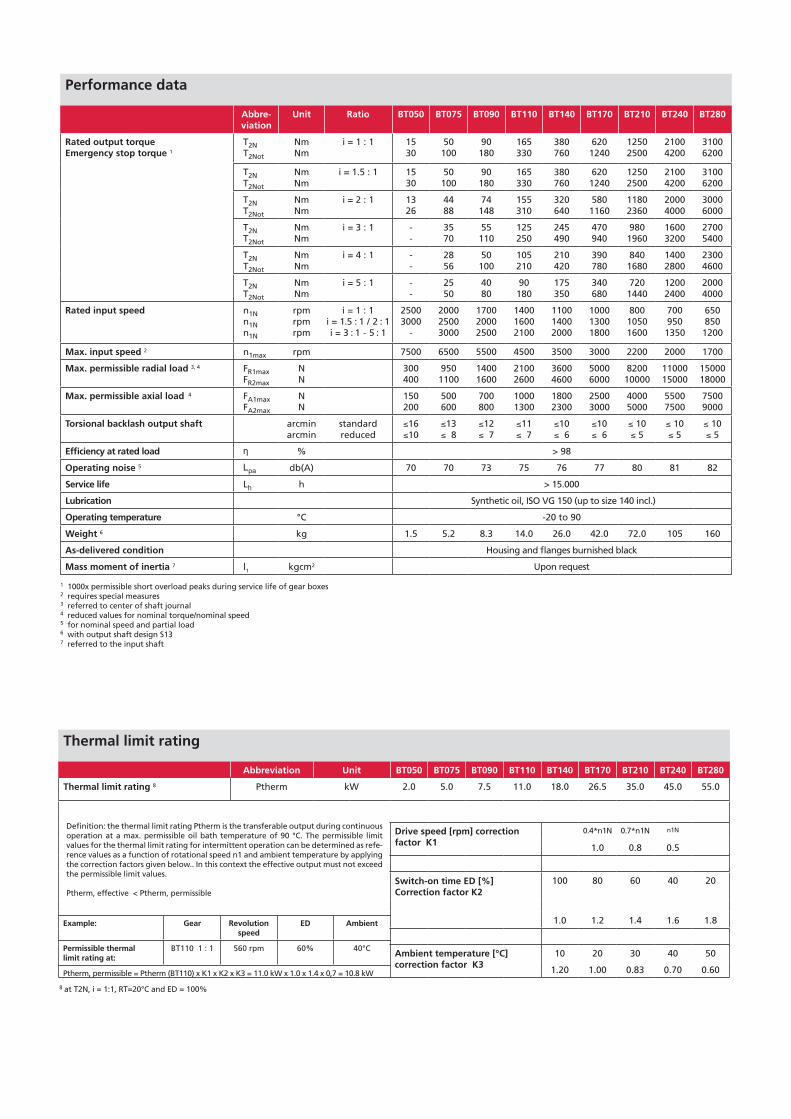
Performance data
Abbre-viation
Unit Ratio BT050 BT075 BT090 BT110 BT140 BT170 BT210 BT240 BT280
Rated output torqueEmergency stop torque 1
T2NT2Not
NmNm
i = 1 : 1 1530
50100
90180
165330
380760
6201240
12502500
21004200
31006200
T2NT2Not
NmNm
i = 1.5 : 1 1530
50100
90180
165330
380760
6201240
12502500
21004200
31006200
T2NT2Not
NmNm
i = 2 : 1 1326
4488
74148
155310
320640
5801160
11802360
20004000
30006000
T2NT2Not
NmNm
i = 3 : 1 --
3570
55110
125250
245490
470940
9801960
16003200
27005400
T2NT2Not
NmNm
i = 4 : 1 --
2856
50100
105210
210420
390780
8401680
14002800
23004600
T2NT2Not
NmNm
i = 5 : 1 --
2550
4080
90180
175350
340680
7201440
12002400
20004000
Rated input speed n1Nn1Nn1N
rpmrpmrpm
i = 1 : 1i = 1.5 : 1 / 2 : 1i = 3 : 1 - 5 : 1
25003000
-
200025003000
170020002500
140016002100
110014002000
100013001800
80010501600
700950
1350
6508501200
Max. input speed 2 n1max rpm 7500 6500 5500 4500 3500 3000 2200 2000 1700
Max. permissible radial load 3, 4 FR1maxFR2max
NN
300400
9501100
14001600
21002600
36004600
50006000
820010000
1100015000
1500018000
Max. permissible axial load 4 FA1maxFA2max
NN
150200
500600
700800
10001300
18002300
25003000
40005000
55007500
75009000
Torsional backlash output shaft arcminarcmin
standardreduced
≤16≤10
≤13≤ 8
≤12≤ 7
≤11≤ 7
≤10≤ 6
≤10≤ 6
≤ 10≤ 5
≤ 10≤ 5
≤ 10≤ 5
Efficiency at rated load η % > 98
Operating noise 5 Lpa db(A) 70 70 73 75 76 77 80 81 82
Service life Lh h > 15.000
Lubrication Synthetic oil, ISO VG 150 (up to size 140 incl.)
Operating temperature °C -20 to 90
Weight 6 kg 1.5 5.2 8.3 14.0 26.0 42.0 72.0 105 160
As-delivered condition Housing and flanges burnished black
Mass moment of inertia 7 l1 kgcm2 Upon request
EPPINGER BT bevel gear boxes
1 1000x permissible short overload peaks during service life of gear boxes2 requires special measures3 referred to center of shaft journal4 reduced values for nominal torque/nominal speed5 for nominal speed and partial load6 with output shaft design S13 7 referred to the input shaft
Thermal limit rating
Abbreviation Unit BT050 BT075 BT090 BT110 BT140 BT170 BT210 BT240 BT280
Thermal limit rating 8 Ptherm kW 2.0 5.0 7.5 11.0 18.0 26.5 35.0 45.0 55.0
Definition: the thermal limit rating Ptherm is the transferable output during continuous operation at a max. permissible oil bath temperature of 90 °C. The permissible limit values for the thermal limit rating for intermittent operation can be determined as refe-rence values as a function of rotational speed n1 and ambient temperature by applying the correction factors given below.. In this context the effective output must not exceed the permissible limit values. Ptherm, effective < Ptherm, permissible
Drive speed [rpm] correction factor K1
0.4*n1N 0.7*n1N n1N
1.0 0.8 0.5
Switch-on time ED [%] Correction factor K2
100 80 60 40 20
1.0 1.2 1.4 1.6 1.8
Ambient temperature [°C] correction factor K3
10 20 30 40 50
1.20 1.00 0.83 0.70 0.60
Example: Gear Revolution speed
ED Ambient
Permissible thermallimit rating at:
BT110 1 : 1 560 rpm 60% 40°C
Ptherm, permissible = Ptherm (BT110) x K1 x K2 x K3 = 11.0 kW x 1.0 x 1.4 x 0,7 = 10.8 kW
8 at T2N, i = 1:1, RT=20°C and ED = 100%
B
B
L6
L4
L8
L4
L8
L6
CC
L5
L8
A
L7
B L3
A
D4
D4
D2
D2
L2 L2
D1
D5
C
L9
L3
M1
P2 P2
M3 M3
P1
M2
Seite 4
side 4
Seite 2
side 2
Seite 1
side 1
Seite 5
side 5
Seite A
side A
Seite 3
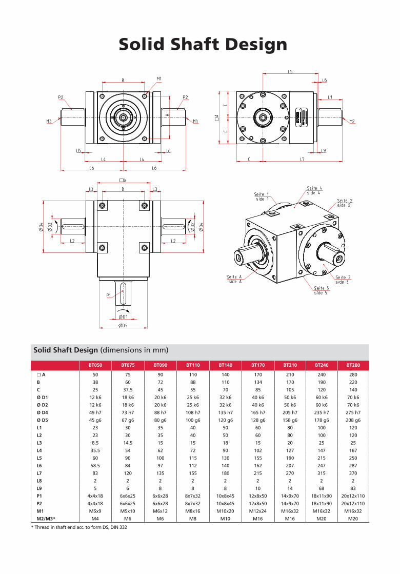
Solid Shaft Design
* Thread in shaft end acc. to form DS, DIN 332
Solid Shaft Design (dimensions in mm)
BT050 BT075 BT090 BT110 BT140 BT170 BT210 BT240 BT280
☐ A 50 75 90 110 140 170 210 240 280
B 38 60 72 88 110 134 170 190 220
C 25 37.5 45 55 70 85 105 120 140
Ø D1 12 k6 18 k6 20 k6 25 k6 32 k6 40 k6 50 k6 60 k6 70 k6
Ø D2 12 k6 18 k6 20 k6 25 k6 32 k6 40 k6 50 k6 60 k6 70 k6
Ø D4 49 h7 73 h7 88 h7 108 h7 135 h7 165 h7 205 h7 235 h7 275 h7
Ø D5 45 g6 67 g6 80 g6 100 g6 120 g6 128 g6 158 g6 178 g6 208 g6
L1 23 30 35 40 50 60 80 100 120
L2 23 30 35 40 50 60 80 100 120
L3 8.5 14.5 15 15 18 15 20 25 25
L4 35.5 54 62 72 90 102 127 147 167
L5 60 90 100 115 130 155 190 215 250
L6 58.5 84 97 112 140 162 207 247 287
L7 83 120 135 155 180 215 270 315 370
L8 2 2 2 2 2 2 2 2 2
L9 5 6 8 8 8 10 14 68 83
P1 4x4x18 6x6x25 6x6x28 8x7x32 10x8x45 12x8x50 14x9x70 18x11x90 20x12x110
P2 4x4x18 6x6x25 6x6x28 8x7x32 10x8x45 12x8x50 14x9x70 18x11x90 20x12x110
M1 M5x9 M5x10 M6x12 M8x16 M10x20 M12x24 M16x32 M16x32 M16x32
M2/M3* M4 M6 M6 M8 M10 M16 M16 M20 M20
B
B
L4
L8
L4
L8
CC
L5
A
L7
B
L3A
D4
D4
D3
D1
D5
C
L9
L3
P3
M1
P1
M2
Seite 4
side 4
Seite 2
side 2
Seite 1
side 1
Seite 5
side 5
Seite A
side ASeite 3
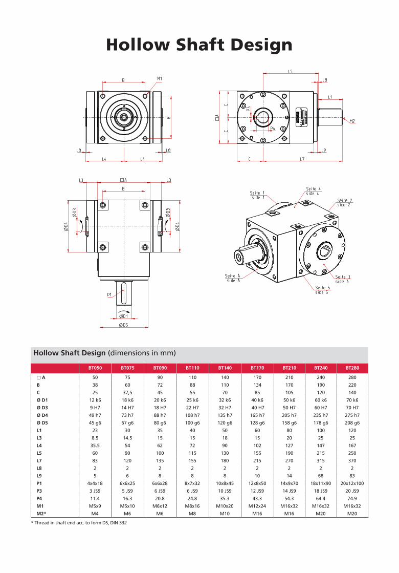
Hollow Shaft Design (dimensions in mm)
BT050 BT075 BT090 BT110 BT140 BT170 BT210 BT240 BT280
☐ A 50 75 90 110 140 170 210 240 280
B 38 60 72 88 110 134 170 190 220
C 25 37,5 45 55 70 85 105 120 140
Ø D1 12 k6 18 k6 20 k6 25 k6 32 k6 40 k6 50 k6 60 k6 70 k6
Ø D3 9 H7 14 H7 18 H7 22 H7 32 H7 40 H7 50 H7 60 H7 70 H7
Ø D4 49 h7 73 h7 88 h7 108 h7 135 h7 165 h7 205 h7 235 h7 275 h7
Ø D5 45 g6 67 g6 80 g6 100 g6 120 g6 128 g6 158 g6 178 g6 208 g6
L1 23 30 35 40 50 60 80 100 120
L3 8.5 14.5 15 15 18 15 20 25 25
L4 35.5 54 62 72 90 102 127 147 167
L5 60 90 100 115 130 155 190 215 250
L7 83 120 135 155 180 215 270 315 370
L8 2 2 2 2 2 2 2 2 2
L9 5 6 8 8 8 10 14 68 83
P1 4x4x18 6x6x25 6x6x28 8x7x32 10x8x45 12x8x50 14x9x70 18x11x90 20x12x100
P3 3 JS9 5 JS9 6 JS9 6 JS9 10 JS9 12 JS9 14 JS9 18 JS9 20 JS9
P4 11.4 16.3 20.8 24.8 35.3 43.3 54.3 64.4 74.9
M1 M5x9 M5x10 M6x12 M8x16 M10x20 M12x24 M16x32 M16x32 M16x32
M2* M4 M6 M6 M8 M10 M16 M16 M20 M20
Hollow Shaft Design
* Thread in shaft end acc. to form DS, DIN 332
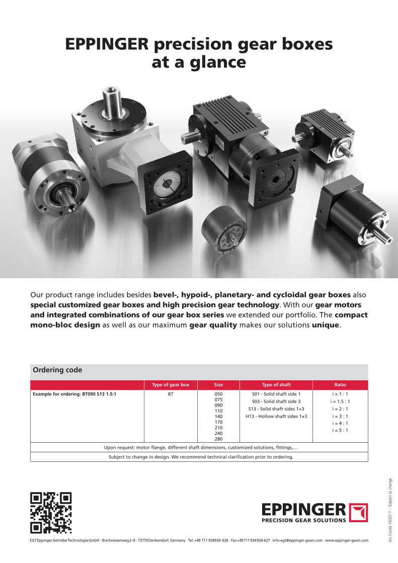
EPPINGER precision gear boxesat a glance
EGT Eppinger Getriebe Technologie GmbH · Breitwiesenweg 2 - 8 · 73770 Denkendorf, Germany · Tel. +49 711 934934 - 626 · Fax +49 711 934 934-627 · [email protected] · www.eppinger-gears.com Ars
Cor
dis
10/2
017
– Su
bjec
t to
cha
nge
Hollow Shaft Design
Ordering code
Type of gear box Size Type of shaft Ratio
Example for ordering: BT090 S13 1.5:1 BT 050075090110140170210240280
S01 - Solid shaft side 1 i = 1 : 1
S03 - Solid shaft side 3 i = 1.5 : 1
S13 - Solid shaft sides 1+3 i = 2 : 1
H13 - Hollow shaft sides 1+3 i = 3 : 1
i = 4 : 1
i = 5 : 1
Upon request: motor flange, different shaft dimensions, customized solutions, fittings,....
Subject to change in design. We recommend technical clarification prior to ordering.
EPPINGER precision gear boxesat a glance
Our product range includes besides bevel-, hypoid-, planetary- and cycloidal gear boxes also special customized gear boxes and high precision gear technology. With our gear motors and integrated combinations of our gear box series we extended our portfolio. The compact mono-bloc design as well as our maximum gear quality makes our solutions unique.