Embed Size (px)
Citation preview
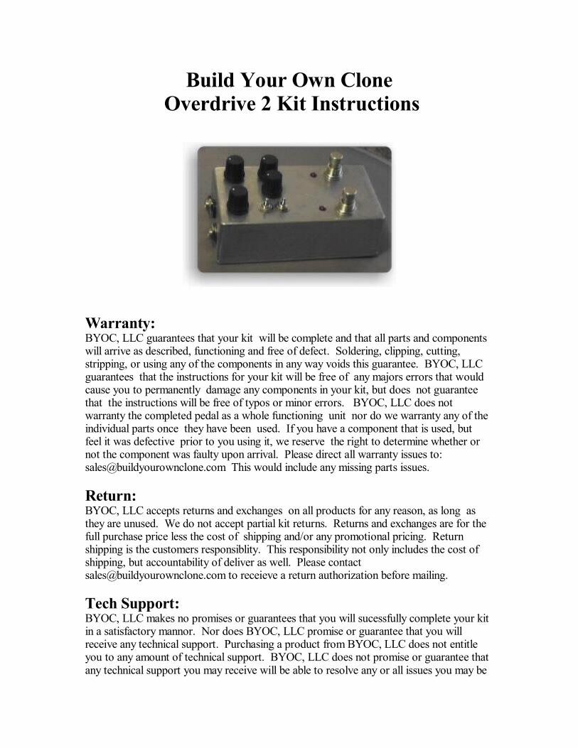
Build Your Own Clone Overdrive 2 Kit Instructions
Warranty:BYOC, LLC guarantees that your kit will be complete and that all parts and componentswill arrive as described, functioning and free of defect. Soldering, clipping, cutting,stripping, or using any of the components in any way voids this guarantee. BYOC, LLCguarantees that the instructions for your kit will be free of any majors errors that wouldcause you to permanently damage any components in your kit, but does not guaranteethat the instructions will be free of typos or minor errors. BYOC, LLC does notwarranty the completed pedal as a whole functioning unit nor do we warranty any of theindividual parts once they have been used. If you have a component that is used, butfeel it was defective prior to you using it, we reserve the right to determine whether ornot the component was faulty upon arrival. Please direct all warranty issues to:[email protected] This would include any missing parts issues.
Return:BYOC, LLC accepts returns and exchanges on all products for any reason, as long asthey are unused. We do not accept partial kit returns. Returns and exchanges are for thefull purchase price less the cost of shipping and/or any promotional pricing. Returnshipping is the customers responsiblity. This responsibility not only includes the cost ofshipping, but accountability of deliver as well. Please [email protected] to receieve a return authorization before mailing.
Tech Support:BYOC, LLC makes no promises or guarantees that you will sucessfully complete your kitin a satisfactory mannor. Nor does BYOC, LLC promise or guarantee that you willreceive any technical support. Purchasing a product from BYOC, LLC does not entitleyou to any amount of technical support. BYOC, LLC does not promise or guarantee thatany technical support you may receive will be able to resolve any or all issues you may be
experiencing.
That being said, we will do our best to help you as much as we can. Our philosophy atBYOC is that we will help you only as much as you are willing to help yourself. We havea wonderful and friendly DIY discussion forum with an entire section devoted to thetechnical support and modifications of BYOC kits.
www.buildyourownclone.com/board
When posting a tech support thread on the BYOC forum, please post it in the correctlounge, and please title your thread appropriately. If everyone titles their threadsHELP! , then it makes it impossible for the people who are helping you to keep track of
your progress. A very brief discription of your specific problem will do. It will also makeit easier to see if someone else is having or has had the same problem as you. Thequestion you are about to ask may already be answered. Here are a list of things that youshould include in the body of your tech support thread:1. A detailed explanation of what the problem is. (not just, It doesn t work, help )2. Pic of the top side of your PCB.3. Pic of the underside of your PCB.4. Pic that clearly shows your footswitch/jack wiring and the wires going to the PCB5. A pic that clearly shows your wiring going from the PCB to the pots and any otherswitches(only if your kit has non-PC mounted pots and switches)6. Is bypass working?7. Does the LED come on?8. If you answer yes to 6 and 7, what does the pedal do when it is "on"?9. Battery or adapter.(if battery, is it good? If adapter, what type?)
Also, please only post pics that are in focus. You're only wasting both parties' time if youpost out of focus, low res pics from your cell phone.
Revision Notes:Rev 1.0 There is a trace touching one of the eyelets for the mids toggle switch.Rev 1.1 (released 2/5/09) Fixed the trace error.
Copyrights:All material in this document is copyrighted 2009 by BYOC, LLC
OVERDRIVE 2 KITINSTRUCTION INDEX
Parts Checklist .............. .....page 4 - 6
Standard Spec Build Notes........................................page 7 - 8
MOSFET Spec Build Notes.......................................page 9 - 11
Populating the Circuit Board ...................page 12 - 22
Assembly ....................page 23 - 25
Wiring the Footswitch & Jacks................................page 26 - 28
Installing the ICs........................................................page 29
Setting up the Internal Trimpots.............................page 30 -31
More Modifications...................................................page 32 - 35
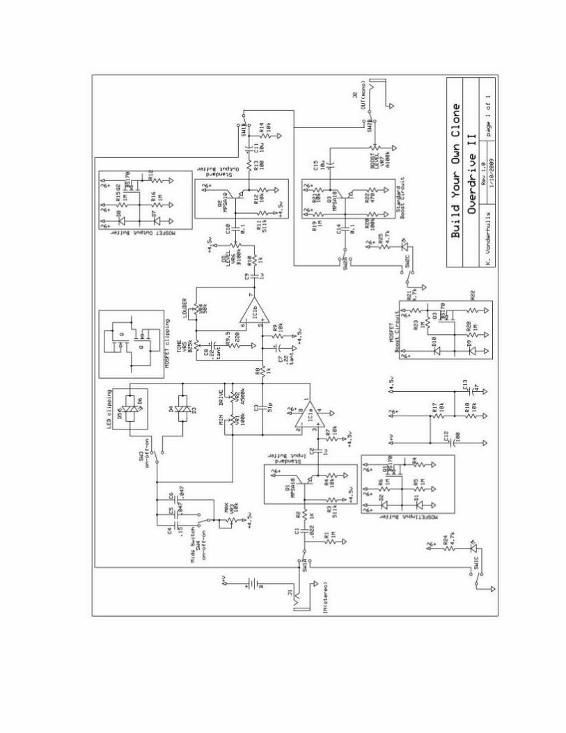
Schematic....................................................................page 36 -37
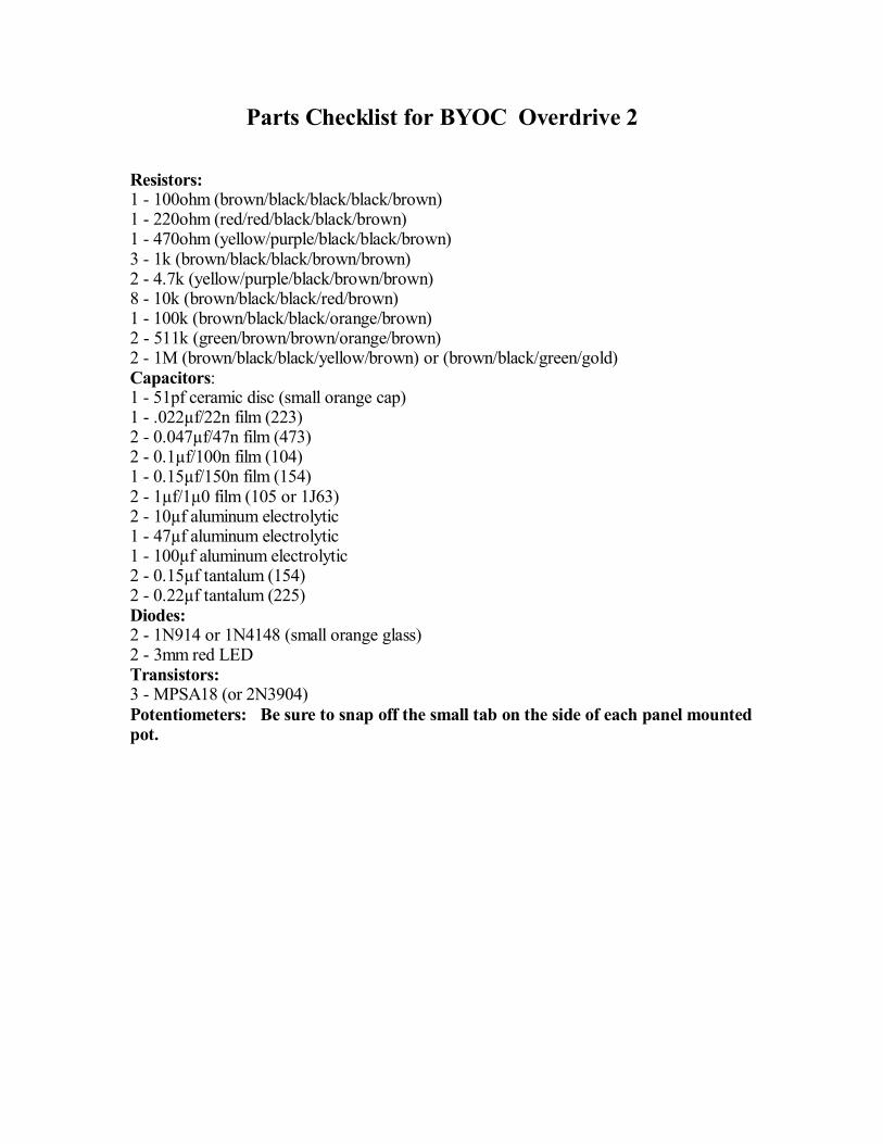
Parts Checklist for BYOC Overdrive 2
Resistors:1 - 100ohm (brown/black/black/black/brown)1 - 220ohm (red/red/black/black/brown)1 - 470ohm (yellow/purple/black/black/brown)3 - 1k (brown/black/black/brown/brown)2 - 4.7k (yellow/purple/black/brown/brown)8 - 10k (brown/black/black/red/brown)1 - 100k (brown/black/black/orange/brown)2 - 511k (green/brown/brown/orange/brown)2 - 1M (brown/black/black/yellow/brown) or (brown/black/green/gold)Capacitors:1 - 51pf ceramic disc (small orange cap)1 - .022µf/22n film (223)2 - 0.047µf/47n film (473)2 - 0.1µf/100n film (104)1 - 0.15µf/150n film (154)2 - 1µf/1µ0 film (105 or 1J63)2 - 10µf aluminum electrolytic1 - 47µf aluminum electrolytic1 - 100µf aluminum electrolytic2 - 0.15µf tantalum (154)2 - 0.22µf tantalum (225)Diodes:2 - 1N914 or 1N4148 (small orange glass)2 - 3mm red LEDTransistors:3 - MPSA18 (or 2N3904)Potentiometers: Be sure to snap off the small tab on the side of each panel mountedpot.
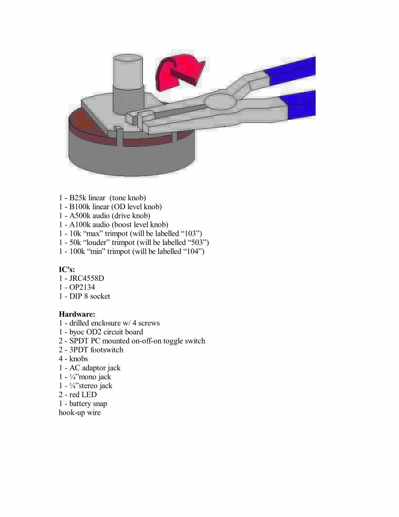
1 - B25k linear (tone knob)1 - B100k linear (OD level knob)1 - A500k audio (drive knob)1 - A100k audio (boost level knob)1 - 10k max trimpot (will be labelled 103 )1 - 50k louder trimpot (will be labelled 503 )1 - 100k min trimpot (will be labelled 104 )
IC's:1 - JRC4558D1 - OP21341 - DIP 8 socket
Hardware:1 - drilled enclosure w/ 4 screws1 - byoc OD2 circuit board2 - SPDT PC mounted on-off-on toggle switch2 - 3PDT footswitch4 - knobs1 - AC adaptor jack1 - ¼ mono jack1 - ¼ stereo jack2 - red LED1 - battery snaphook-up wire
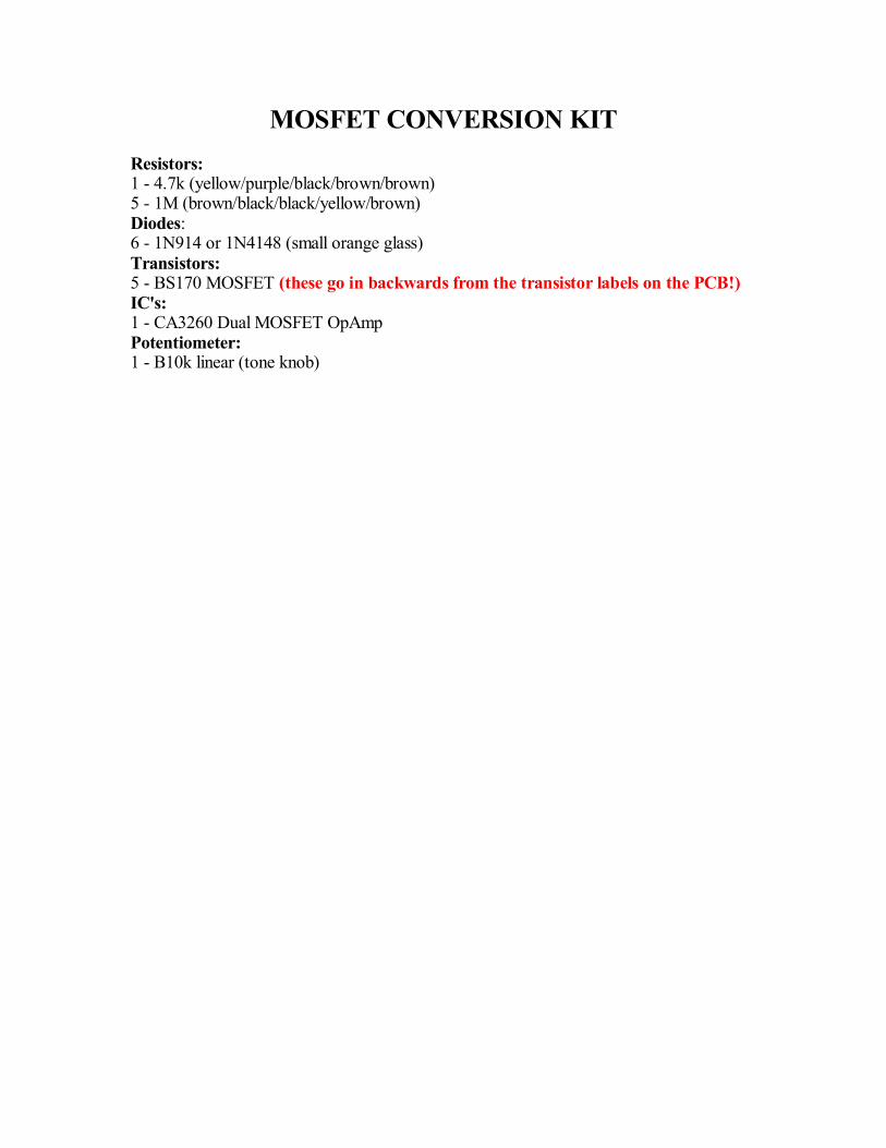
MOSFET CONVERSION KITResistors:1 - 4.7k (yellow/purple/black/brown/brown)5 - 1M (brown/black/black/yellow/brown)Diodes:6 - 1N914 or 1N4148 (small orange glass)Transistors:5 - BS170 MOSFET (these go in backwards from the transistor labels on the PCB!)IC's:1 - CA3260 Dual MOSFET OpAmpPotentiometer:1 - B10k linear (tone knob)
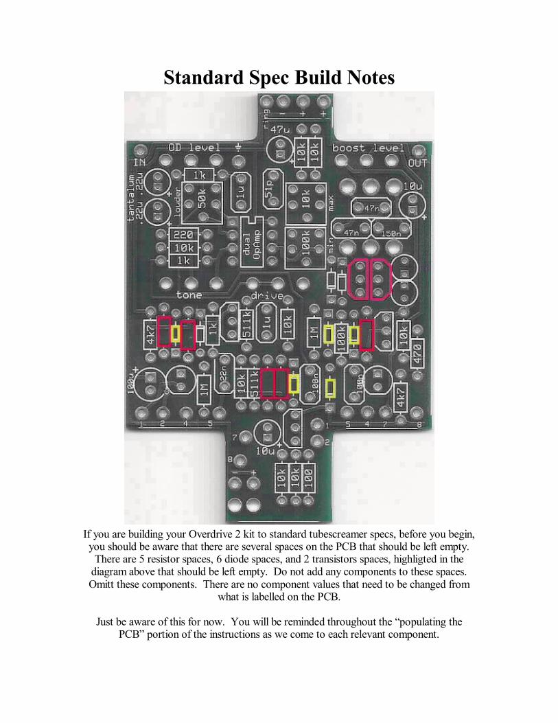
Standard Spec Build Notes
If you are building your Overdrive 2 kit to standard tubescreamer specs, before you begin,you should be aware that there are several spaces on the PCB that should be left empty.
There are 5 resistor spaces, 6 diode spaces, and 2 transistors spaces, highligted in thediagram above that should be left empty. Do not add any components to these spaces.Omitt these components. There are no component values that need to be changed from
what is labelled on the PCB.
Just be aware of this for now. You will be reminded throughout the populating thePCB portion of the instructions as we come to each relevant component.
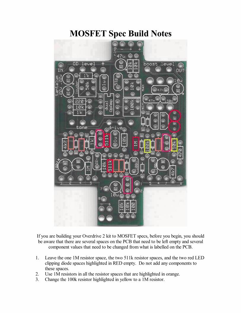
MOSFET Spec Build Notes
If you are building your Overdrive 2 kit to MOSFET specs, before you begin, you shouldbe aware that there are several spaces on the PCB that need to be left empty and several
component values that need to be changed from what is labelled on the PCB.
1. Leave the one 1M resistor space, the two 511k resistor spaces, and the two red LEDclipping diode spaces highlighted in RED empty. Do not add any components tothese spaces.
2. Use 1M resistors in all the resistor spaces that are highlighted in orange.3. Change the 100k resistor highlighted in yellow to a 1M resistor.
4. Change the 10k resistor highlighted in yellow to a 4.7k resistor.5. Change the 3 MPSA18 transistors highlighted in pink to BS170 MOSFETs. The
BS170 MOSFET transistors need to go in backwards.6. Replace the 25k tone potentiometer with the 10k potentiometer.
Just be aware of this for now. You will be reminded throughout the populating thePCB portion of the instructions as we come to each relevant component. All of the othertypical tubescreamer mods will still apply to the circuit even after MOSFET conversion.
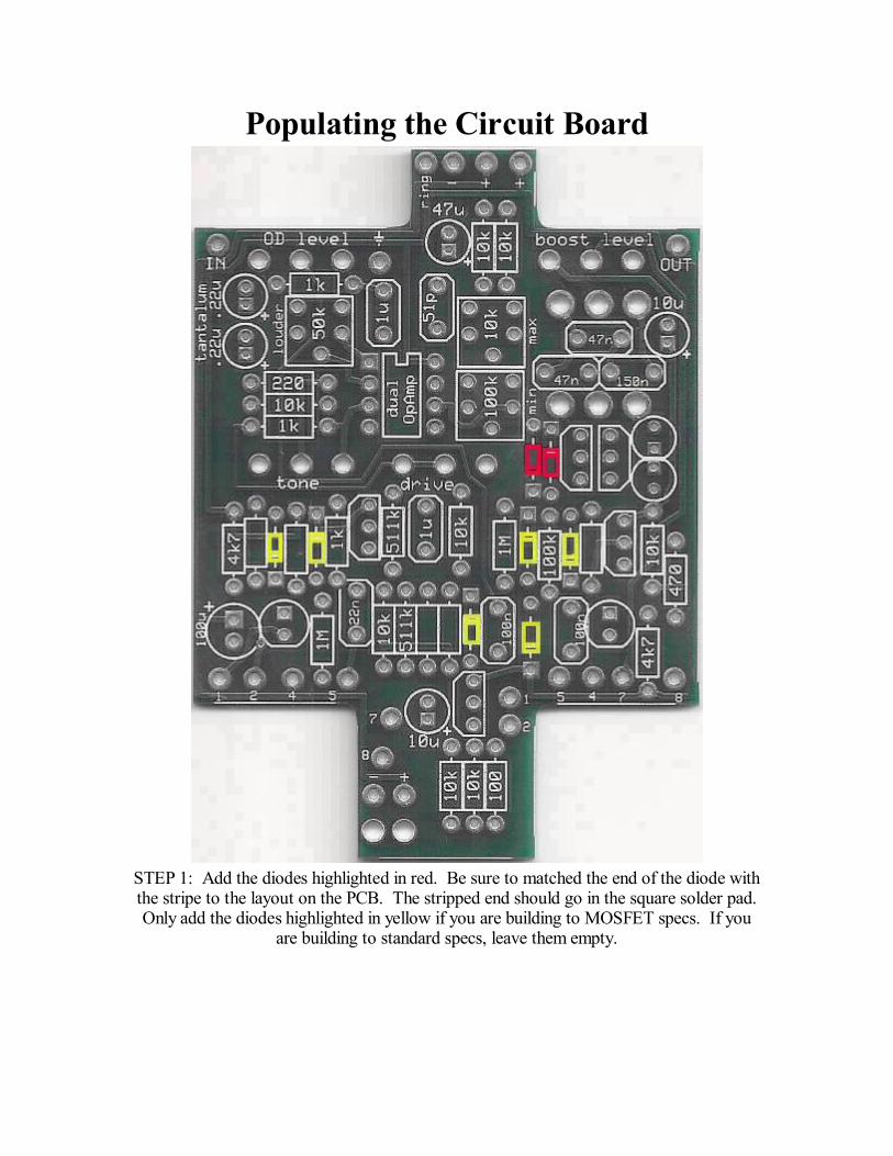
Populating the Circuit Board
STEP 1: Add the diodes highlighted in red. Be sure to matched the end of the diode withthe stripe to the layout on the PCB. The stripped end should go in the square solder pad.Only add the diodes highlighted in yellow if you are building to MOSFET specs. If you
are building to standard specs, leave them empty.
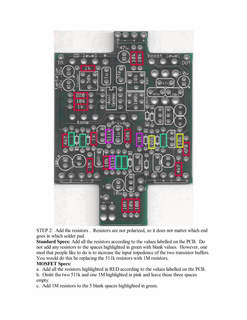
STEP 2: Add the resistors . Resistors are not polarized, so it does not matter which endgoes in which solder pad.Standard Specs: Add all the resistors according to the values labelled on the PCB. Donot add any resistors to the spaces highlighted in green with blank values. However, onemod that people like to do is to increase the input impedence of the two transistor buffers.You would do this be replacing the 511k resistors with 1M resistors.MOSFET Specs:a. Add all the resistors highlighted in RED according to the values labelled on the PCB.b. Omitt the two 511k and one 1M highlighted in pink and leave these three spacesempty.c. Add 1M resistors to the 5 blank spaces highlighted in green.
d. Change the 100k to 1M and change the 10k to 4.7k in the spaces highlighted in yellow.
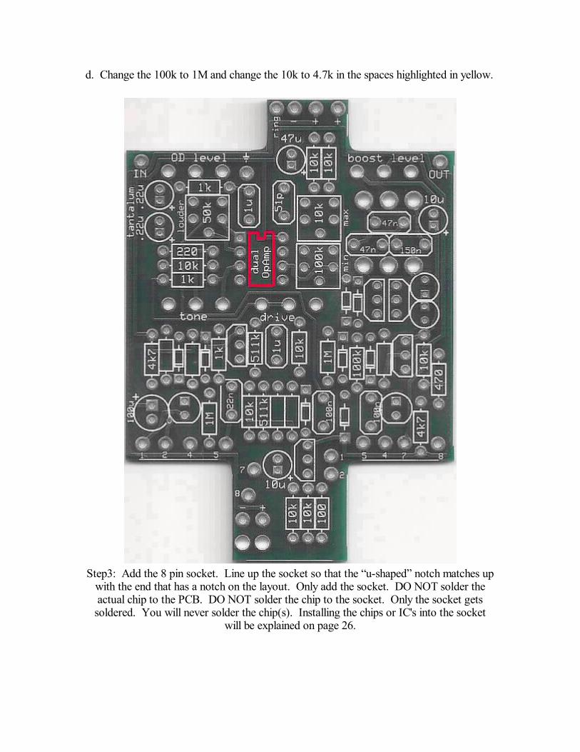
Step3: Add the 8 pin socket. Line up the socket so that the u-shaped notch matches upwith the end that has a notch on the layout. Only add the socket. DO NOT solder theactual chip to the PCB. DO NOT solder the chip to the socket. Only the socket gets
soldered. You will never solder the chip(s). Installing the chips or IC's into the socketwill be explained on page 26.
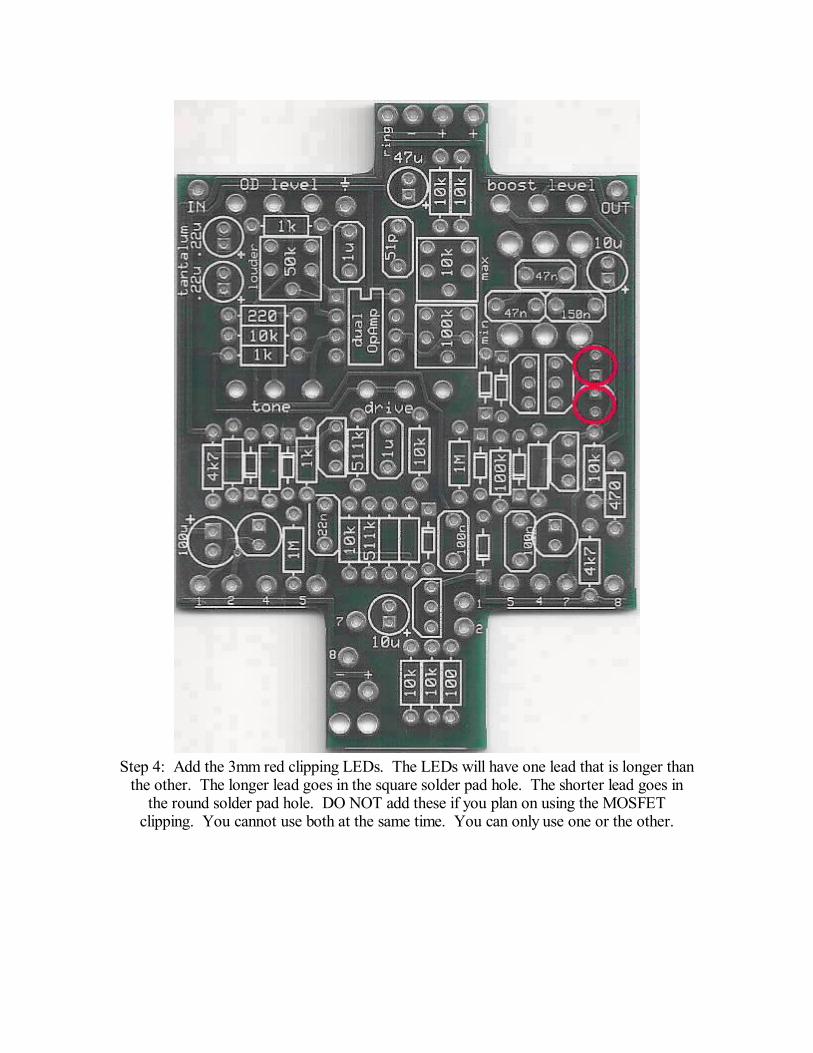
Step 4: Add the 3mm red clipping LEDs. The LEDs will have one lead that is longer thanthe other. The longer lead goes in the square solder pad hole. The shorter lead goes in
the round solder pad hole. DO NOT add these if you plan on using the MOSFETclipping. You cannot use both at the same time. You can only use one or the other.
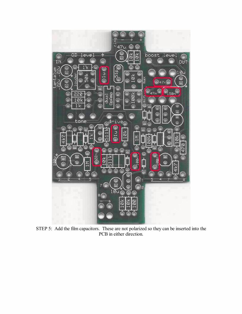
STEP 5: Add the film capacitors. These are not polarized so they can be inserted into thePCB in either direction.
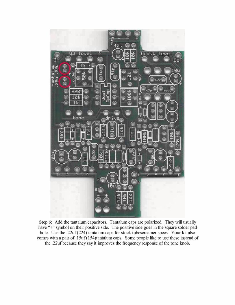
Step 6: Add the tantalum capacitors. Tantalum caps are polarized. They will usuallyhave + symbol on their positive side. The positive side goes in the square solder padhole. Use the .22uf (224) tantalum caps for stock tubescreamer specs. Your kit also
comes with a pair of .15uf (154)tantalum caps. Some people like to use these instead ofthe .22uf because they say it improves the frequency response of the tone knob.
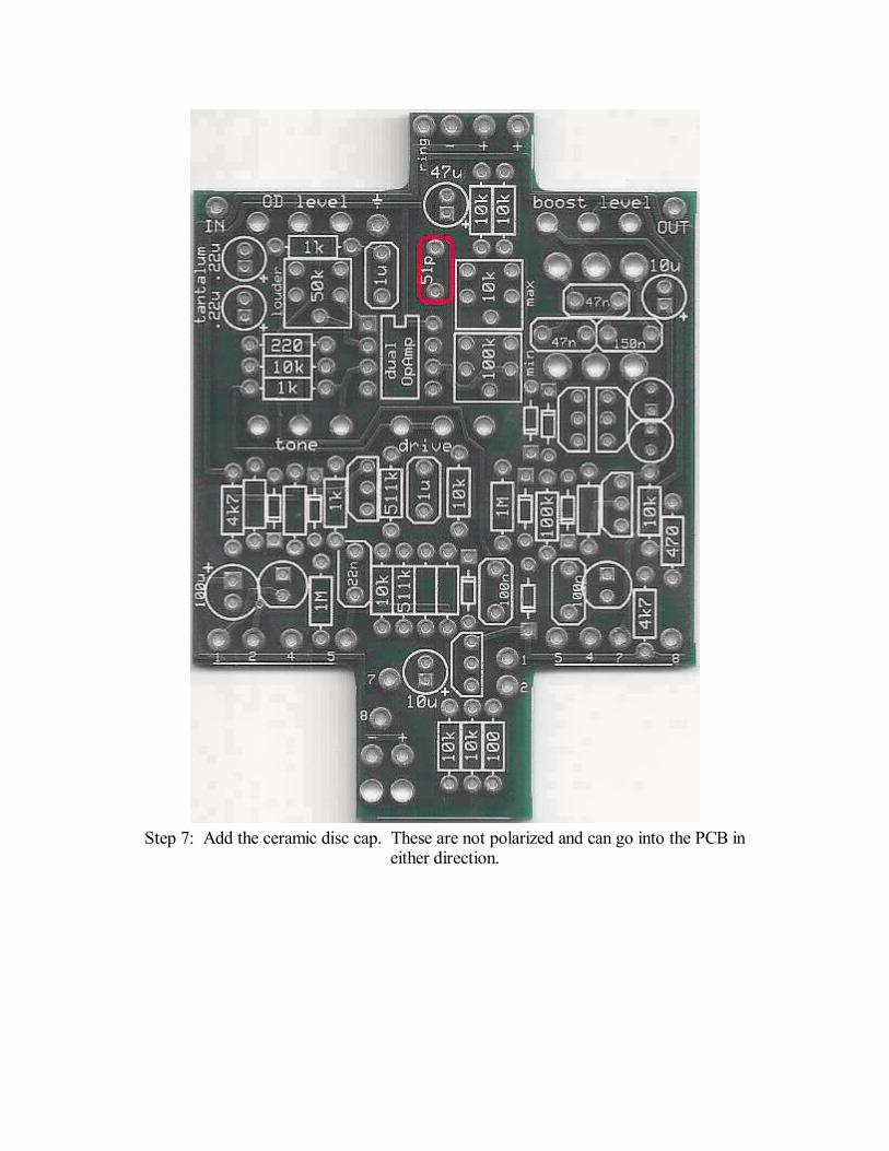
Step 7: Add the ceramic disc cap. These are not polarized and can go into the PCB ineither direction.
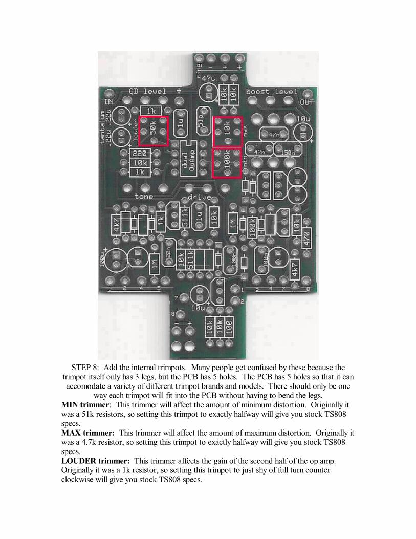
STEP 8: Add the internal trimpots. Many people get confused by these because thetrimpot itself only has 3 legs, but the PCB has 5 holes. The PCB has 5 holes so that it canaccomodate a variety of different trimpot brands and models. There should only be one
way each trimpot will fit into the PCB without having to bend the legs.MIN trimmer: This trimmer will affect the amount of minimum distortion. Originally itwas a 51k resistors, so setting this trimpot to exactly halfway will give you stock TS808specs.MAX trimmer: This trimmer will affect the amount of maximum distortion. Originally itwas a 4.7k resistor, so setting this trimpot to exactly halfway will give you stock TS808specs.LOUDER trimmer: This trimmer affects the gain of the second half of the op amp.Originally it was a 1k resistor, so setting this trimpot to just shy of full turn counterclockwise will give you stock TS808 specs.
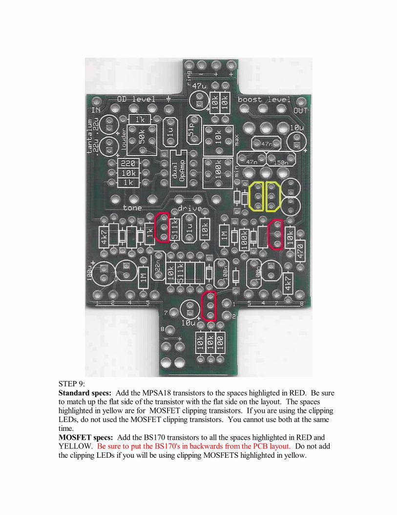
STEP 9:Standard specs: Add the MPSA18 transistors to the spaces highligted in RED. Be sureto match up the flat side of the transistor with the flat side on the layout. The spaceshighlighted in yellow are for MOSFET clipping transistors. If you are using the clippingLEDs, do not used the MOSFET clipping transistors. You cannot use both at the sametime.MOSFET specs: Add the BS170 transistors to all the spaces highlighted in RED andYELLOW. Be sure to put the BS170's in backwards from the PCB layout. Do not addthe clipping LEDs if you will be using clipping MOSFETS highlighted in yellow.
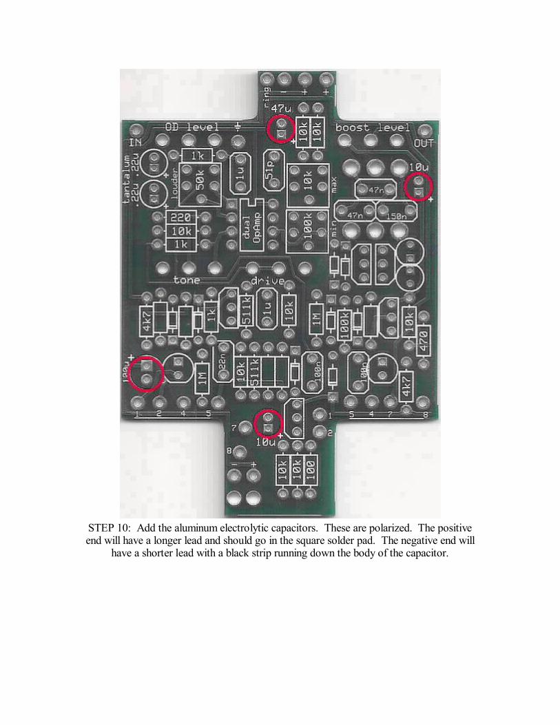
STEP 10: Add the aluminum electrolytic capacitors. These are polarized. The positiveend will have a longer lead and should go in the square solder pad. The negative end will
have a shorter lead with a black strip running down the body of the capacitor.
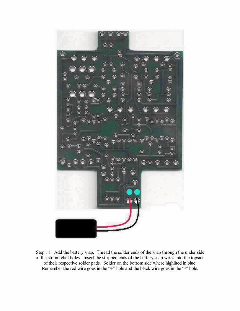
Step 11: Add the battery snap. Thread the solder ends of the snap through the under sideof the strain relief holes. Insert the stripped ends of the battery snap wires into the topside
of their respective solder pads. Solder on the bottom side where highlited in blue.Remember the red wire goes in the + hole and the black wire goes in the - hole.
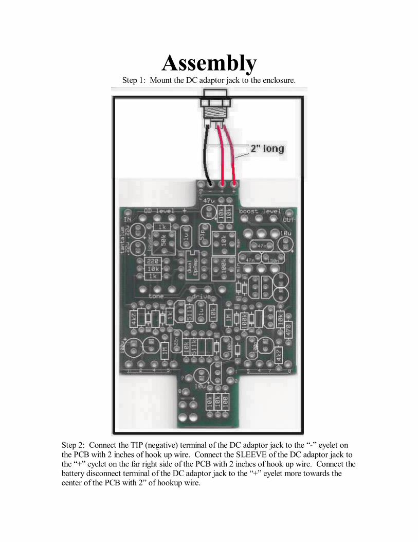
AssemblyStep 1: Mount the DC adaptor jack to the enclosure.
Step 2: Connect the TIP (negative) terminal of the DC adaptor jack to the - eyelet onthe PCB with 2 inches of hook up wire. Connect the SLEEVE of the DC adaptor jack tothe + eyelet on the far right side of the PCB with 2 inches of hook up wire. Connect thebattery disconnect terminal of the DC adaptor jack to the + eyelet more towards thecenter of the PCB with 2 of hookup wire.
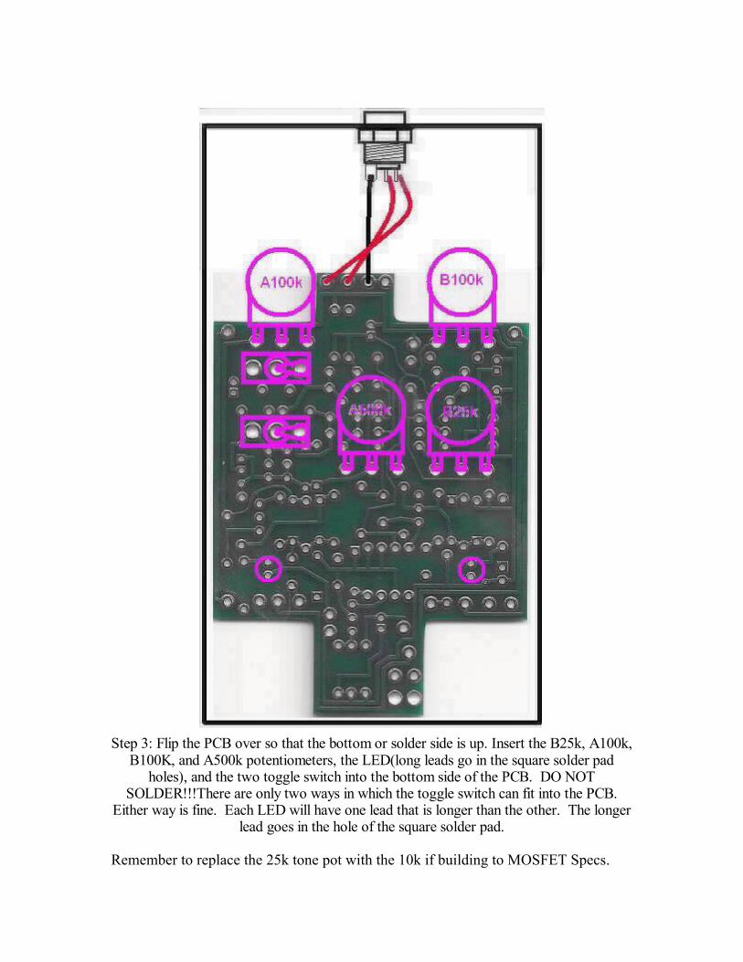
Step 3: Flip the PCB over so that the bottom or solder side is up. Insert the B25k, A100k,B100K, and A500k potentiometers, the LED(long leads go in the square solder pad
holes), and the two toggle switch into the bottom side of the PCB. DO NOTSOLDER!!!There are only two ways in which the toggle switch can fit into the PCB.
Either way is fine. Each LED will have one lead that is longer than the other. The longerlead goes in the hole of the square solder pad.
Remember to replace the 25k tone pot with the 10k if building to MOSFET Specs.
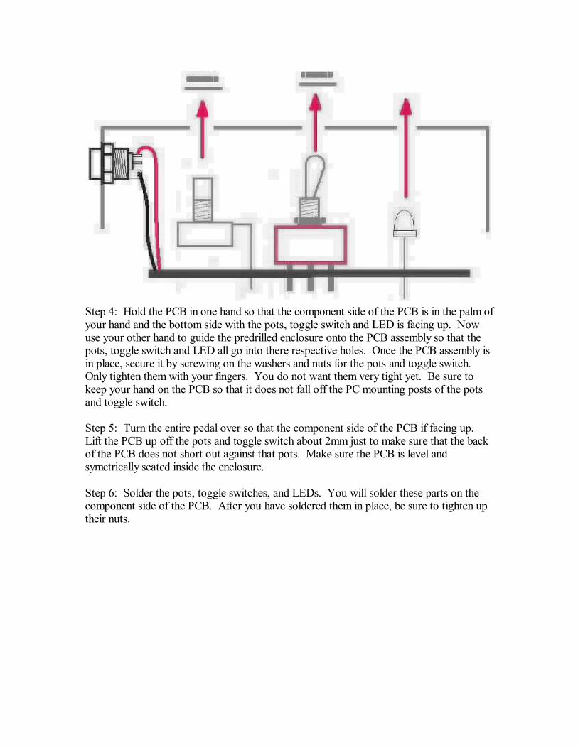
Step 4: Hold the PCB in one hand so that the component side of the PCB is in the palm ofyour hand and the bottom side with the pots, toggle switch and LED is facing up. Nowuse your other hand to guide the predrilled enclosure onto the PCB assembly so that thepots, toggle switch and LED all go into there respective holes. Once the PCB assembly isin place, secure it by screwing on the washers and nuts for the pots and toggle switch.Only tighten them with your fingers. You do not want them very tight yet. Be sure tokeep your hand on the PCB so that it does not fall off the PC mounting posts of the potsand toggle switch.
Step 5: Turn the entire pedal over so that the component side of the PCB if facing up.Lift the PCB up off the pots and toggle switch about 2mm just to make sure that the backof the PCB does not short out against that pots. Make sure the PCB is level andsymetrically seated inside the enclosure.
Step 6: Solder the pots, toggle switches, and LEDs. You will solder these parts on thecomponent side of the PCB. After you have soldered them in place, be sure to tighten uptheir nuts.
Wiring the footswitch, and jacks
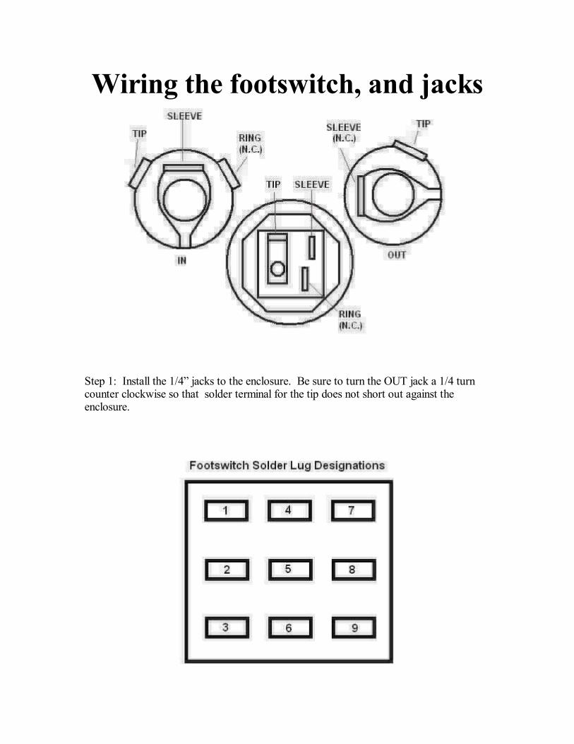
Step 1: Install the 1/4 jacks to the enclosure. Be sure to turn the OUT jack a 1/4 turncounter clockwise so that solder terminal for the tip does not short out against theenclosure.
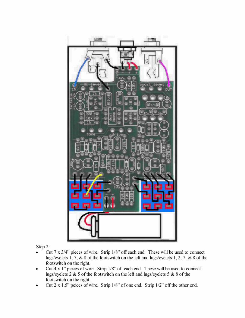
Step 2:· Cut 7 x 3/4 pieces of wire. Strip 1/8 off each end. These will be used to connect
lugs/eyelets 1, 7, & 8 of the footswitch on the left and lugs/eyelets 1, 2, 7, & 8 of thefootswitch on the right.
· Cut 4 x 1 pieces of wire. Strip 1/8 off each end. These will be used to connectlugs/eyelets 2 & 5 of the footswitch on the left and lugs/eyelets 5 & 8 of thefootswitch on the right.
· Cut 2 x 1.5 peices of wire. Strip 1/8 of one end. Strip 1/2 off the other end.
These will be used to connect lugs/eyelets 4 with the longer 1/2 stripped ends beingused to jumper lugs 4 to 9 of both footswitches.
· Cut 3 x 2 pieces of wire. Strip 1/4 off each end. These will be used to connect thetip and sleeve of the IN jack and the tip of the OUT jack to the PCB.
· Cut 1 x 1.5 peice of wire. Strip 1/4 off each end. This will be used to connect thering of the IN jack to the ring eyelet on the PCB.
Step 3: Solder the wires for the footswitch.
Step 4: Remove the PCB assembly from the enclosure. Solder the open ends of the wiresthat you just soldered to the footswitch to their respective eyelets on the PCB. Load thewires in from the top and solder on the bottom side.
Step 5: Reinstall the PCB assembly to the enclosure. Install the footswitch to theenclosure. It will have a white nylon washer and a silver metal washer. You can decidewhich washer you want to be visible on the outside of the enclosure.
Step 6. Solder the jacks to the PCB.
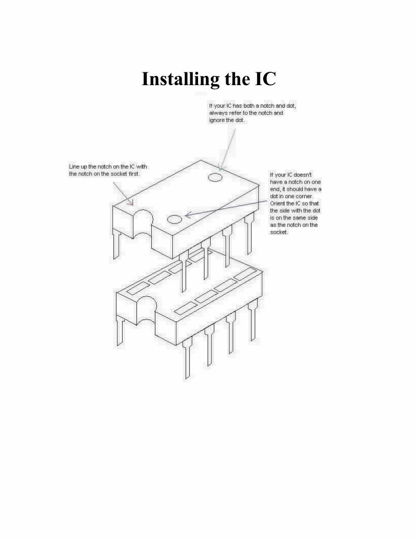
Installing the IC
Adjusting the Trimpots
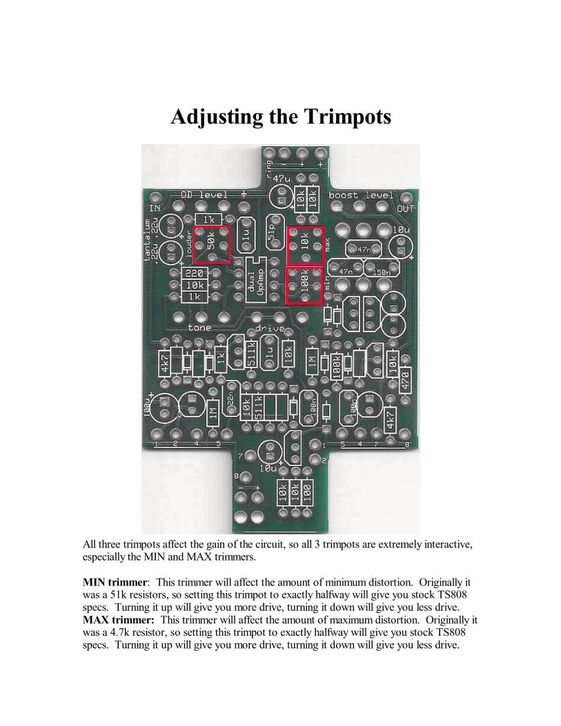
All three trimpots affect the gain of the circuit, so all 3 trimpots are extremely interactive,especially the MIN and MAX trimmers.
MIN trimmer: This trimmer will affect the amount of minimum distortion. Originally itwas a 51k resistors, so setting this trimpot to exactly halfway will give you stock TS808specs. Turning it up will give you more drive, turning it down will give you less drive.MAX trimmer: This trimmer will affect the amount of maximum distortion. Originally itwas a 4.7k resistor, so setting this trimpot to exactly halfway will give you stock TS808specs. Turning it up will give you more drive, turning it down will give you less drive.
Turing it up too much may cause squealing or self-oscillation.LOUDER trimmer: This trimmer affects the gain of the second half of the op amp.Originally it was a 1k resistor, so setting this trimpot to just shy of full turn counterclockwise will give you stock TS808 specs. Turning it up will increase the amount ofdrive and overall output. Turning it up too much may cause squealing or self-oscillationon certain settings. Particularly if you turn the tone knob up all the way full turnclockwise. This mod does not work very well if you built your pedal to MOSFET specs.It will add a lot of noise, so if you built your kit to MOSFET specs, you should turn itdown just about as low as it can go and still give you full range on the tone knob (turningit full turn counter clockwise will make the tone knob less useful).
More Modifications
MOSFET or Standard Specs? Or a little of each?
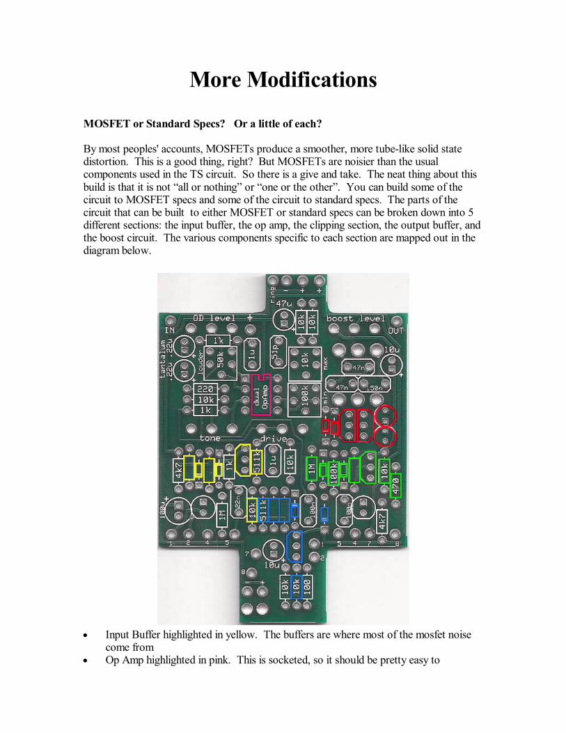
By most peoples' accounts, MOSFETs produce a smoother, more tube-like solid statedistortion. This is a good thing, right? But MOSFETs are noisier than the usualcomponents used in the TS circuit. So there is a give and take. The neat thing about thisbuild is that it is not all or nothing or one or the other . You can build some of thecircuit to MOSFET specs and some of the circuit to standard specs. The parts of thecircuit that can be built to either MOSFET or standard specs can be broken down into 5different sections: the input buffer, the op amp, the clipping section, the output buffer, andthe boost circuit. The various components specific to each section are mapped out in thediagram below.
· Input Buffer highlighted in yellow. The buffers are where most of the mosfet noisecome from
· Op Amp highlighted in pink. This is socketed, so it should be pretty easy to
experiment with. The MOSFET op amp cannot run at more than 9v. But the otherop amps can run at 18v.
· Output buffer highlighted in blue. The buffers are where most of the mosfet noisecomes from.
· Clipping section highlighted in red. Note that while you can use either the MOSFETtransistors as clipping devices or the LEDs as clipping devices regardless of whatspecs you build the rest of the pedal to, you cannot have components on the PCB inboth of these spaces at the same time. It's one or the other in this case. If youwanted both, you'd need to get rid of the stock silicon diode clippers and put theLEDs in their place adn then leave the spaces for the LEDs on the PCB empty.
· Boost Circuit highlighted in green. The standard silicon boost will sound fuller andwill be louder but cannot run at more than 9V. The MOSFET boost will not be asloud as the silicon boost, but it will have some sparkle to it that many guitarist likeand it can run at 18V.
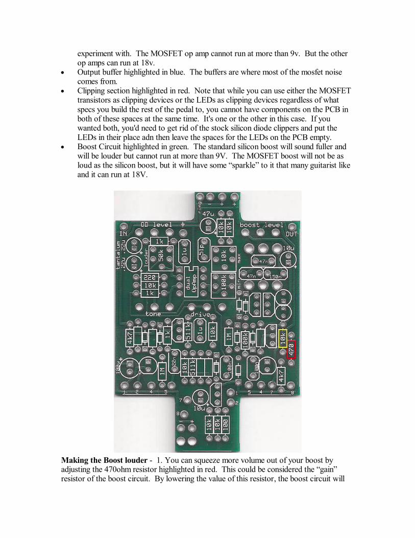
Making the Boost louder - 1. You can squeeze more volume out of your boost byadjusting the 470ohm resistor highlighted in red. This could be considered the gainresistor of the boost circuit. By lowering the value of this resistor, the boost circuit will
produce more gain and volume. The drawback of this is that the boost will becomedirtier as you increase the gain. This mod will work with both the standard and
MOSFET build specs. Try a 100ohm or 220ohm resistor. You can even use a jumper formaximum gain.2. You can also make the standard silicon boost louder and dirtier by increasing the valueof the 10k resistor highlighted in yellow. Try a 15k resistor. This mod will not work withMOSFET build specs.
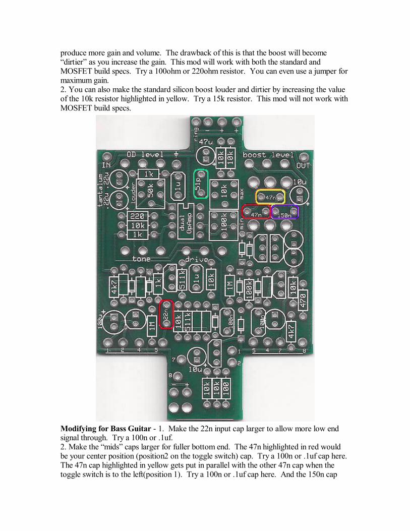
Modifying for Bass Guitar - 1. Make the 22n input cap larger to allow more low endsignal through. Try a 100n or .1uf.2. Make the mids caps larger for fuller bottom end. The 47n highlighted in red wouldbe your center position (position2 on the toggle switch) cap. Try a 100n or .1uf cap here.The 47n cap highlighted in yellow gets put in parallel with the other 47n cap when thetoggle switch is to the left(position 1). Try a 100n or .1uf cap here. And the 150n cap
highlighted in purple gets put into parallel with the cap highlighted in red with the toggleswitch is to the right (position 3). Try a 220n or .22uf cap here.3. Make the 51pf feedback cap larger. Try a 220pf or 330pf.
18 volt operation? - This can be a little tricky. Because the standard spec overdrivecircuit can run just fine at 18v. But the standard silicon boost circuit cannot. 18v will nothurt it, but it will be distorted. The MOSFET boost can run at 18v. But the MOSFEToverdrive circuit cannot. Anymore than 9v will fry the MOSFET op amp. So if you wantto run the pedal at 18v, you'd need to build the overdrive portion of the circuit to standardspecs and build the boost to MOSFET specs.

Please visithttp://buildyourownclone.com/board
for any technical support
copyright 2009B.Y.O.C., LLC