Embed Size (px)
Citation preview
12PACK
Build your own
THUNDERBIRD 2

Editorial and design by Continuo Creative, 39-41 North Road, London N7 9DP.Published in the UK by De Agostini UK Ltd, Battersea Studios 2, 82 Silverthorne Road, London SW8 3HE. Published in the USA by De Agostini Publishing USA, Inc., 121 E. Calhoun Street, Woodstock, IL 60098.All rights reserved © 2017
Warning: Not suitable for children under the age of 14. This product is not a toy and is not designed or intended for use in play. Items may vary from those shown.
Build your own
THUNDERBIRD 2STAGE PAGE
74 Tailwing ramjets and Cobra Half-track 247
75 Tailwing intakes 250
76 Tailwing fins 253
77 T2 control board 255
78 T2 wings and Mobile Crane 258
79 T2 side frames and Mobile Crane 261
80 Complete your Thunderbird 2! 264
Troubleshooting guide 267
.
247
HOW TO BUILD HOW TO BUILDBuild your own
THUNDERBIRD 2
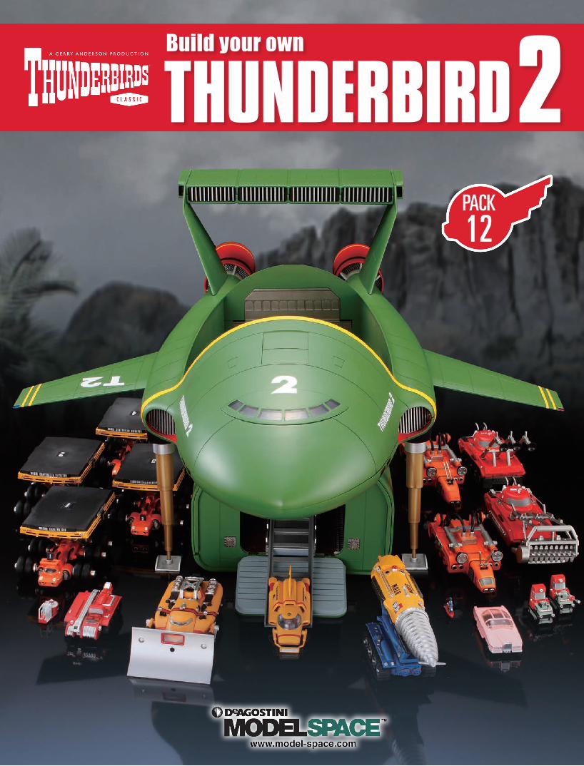
TAILWING RAMJETS
01
+ COBRA HALF-TRACK
STAGE 74
Familiarise yourself with the lower tailwing part.
The left and right backings are marked with an L and an R.
Glue one of the ramjet covers to the right backing, like this.
Now do the same for the central (C) backings...
Repeat for the left backing. ... like this.
Front
Back
YOUR PARTS
01 02
03 04 05 06
Tools and materials: Superglue Tailwing lower
Ramjet covers x 4
Backing R
Backings C x 2
Backing L

248
HOW TO BUILD HOW TO BUILDBuild your own
THUNDERBIRD 2
STAGE COMPLETE
Find these downward-facing hooks on the backings.
... and here.
The backing’s hooks will hold it in position, like this.
All four should look like this.
Glue the right ramjet and backing to these notches at the right-rear of the lower tailwing.
Then glue the left one in place.
Glue the central parts here...
Glue the steering wheel to the dashboard. All details will be glued.
Now glue the dashboard to the main body.
It should be level, like this. The seat goes here.
07
01
11
08
02
12
09
03
13
10
04
COBRA HALF-TRACK
Front
Back
Headlights Windscreen Searchlights x 2 Canopy
Planks x 2
Canvas packs x 2
Steering wheel
Jerry cans x 2
Roll cage
Bonnet rails x 2
Seat
Bulkhead
Dashboard
Tools and materials: Superglue, tweezers
249
HOW TO BUILD HOW TO BUILDBuild your own
THUNDERBIRD 2
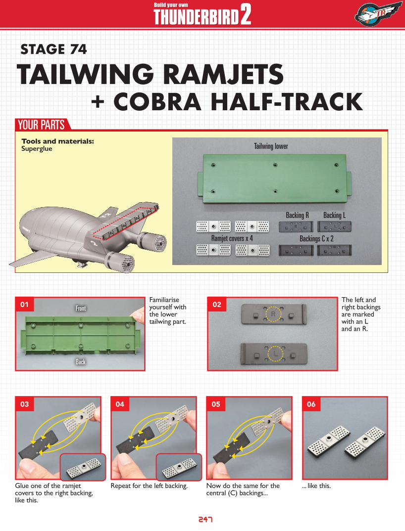
Fit the headlights...
Fit the canvas packs to both sets of planks.
Repeat for the other side.
Repeat for the other side.
Fit the first bonnet rail to these holes.
... with the pack/plank assembly behind it.
Now fit one searchlight here...
The assembly is complete.
... like this.
Glue one of the two jerry cans here...
Glue the windscreen here.
Finally, glue the canopy to these holes.
It should be level.
They should sit like this.
... and the other one next to it.
The bulkhead sits just behind the seat.
The roll cage fits here...These parts should be level with each other, like this.
... like this.
05
09
13
17
21
06
10
14
18
22
07
11
15
19
23
08
12
16
20
STAGE COMPLETE

250
HOW TO BUILD HOW TO BUILDBuild your own
THUNDERBIRD 2STAGE 75
Familiarise yourself with the upper tailwing part.
Locate the R and L marks on the right and left intakes.
Carefully separate the fins from the sprues. These will be glued into the intakes’ vertical grooves, via their central pins (arrow).
This is what each fin will look like. This is the right intake.
Front
Back
TAILWING INTAKESYOUR PARTS
01
03
02
04
Tools and materials: Superglue
Tailwing upperIntake fins x 48
Intake R Intake L
Screws x 7
Intakes C x 2
251
HOW TO BUILD HOW TO BUILDBuild your own
THUNDERBIRD 2
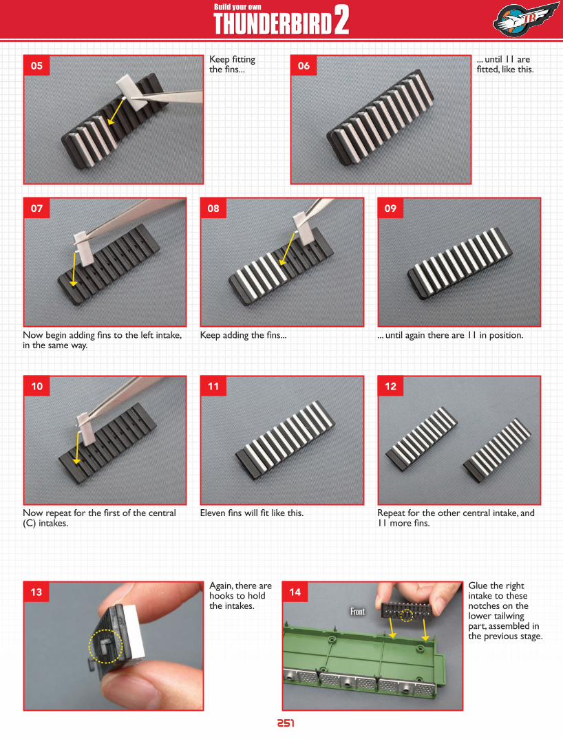
Again, there are hooks to hold the intakes.
Glue the right intake to these notches on the lower tailwing part, assembled in the previous stage.
Eleven fins will fit like this.Now repeat for the first of the central (C) intakes.
Repeat for the other central intake, and 11 more fins.
... until again there are 11 in position.Now begin adding fins to the left intake, in the same way.
Keep adding the fins...
Keep fitting the fins...
... until 11 are fitted, like this.05
07
10
13 14
08
11
09
12
06
Front
252
HOW TO BUILD HOW TO BUILDBuild your own
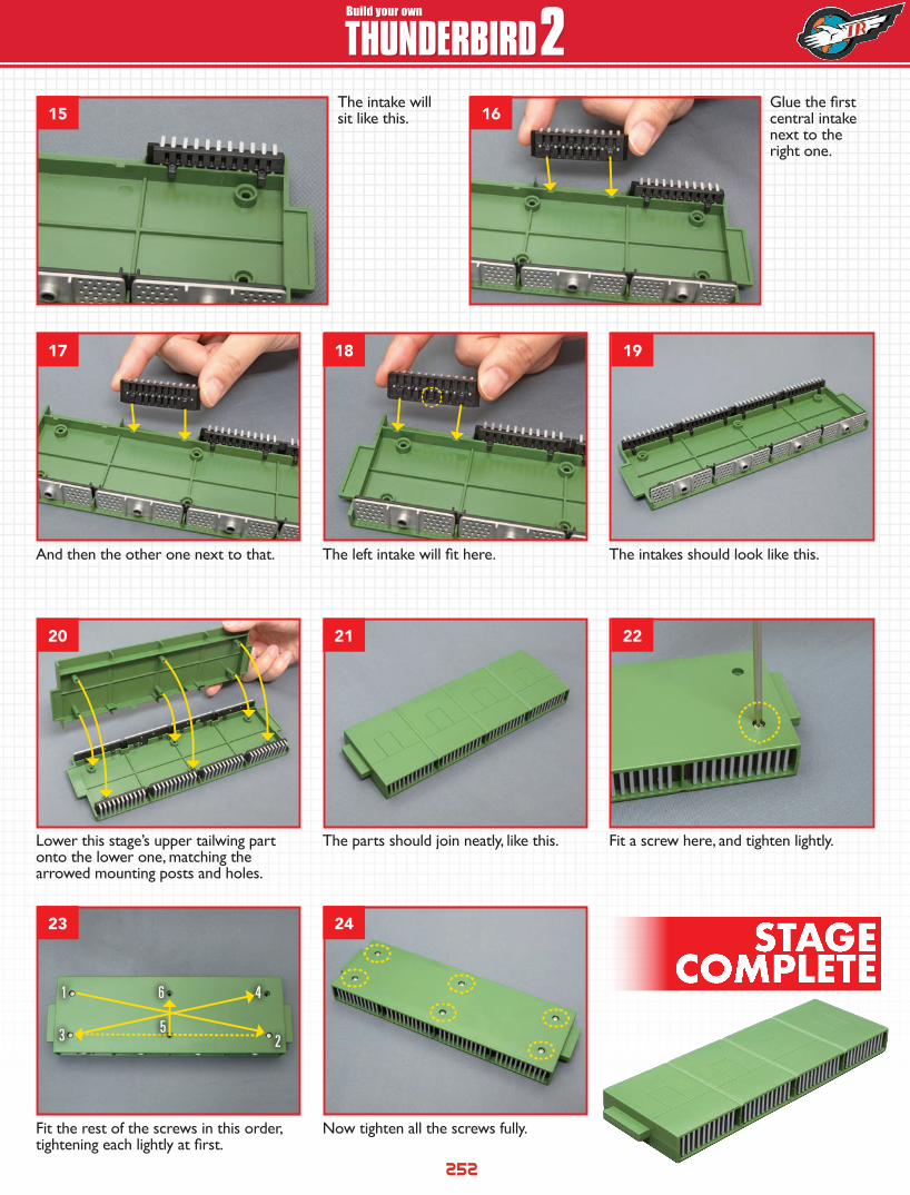
THUNDERBIRD 2The intake will sit like this.
Lower this stage’s upper tailwing part onto the lower one, matching the arrowed mounting posts and holes.
The parts should join neatly, like this. Fit a screw here, and tighten lightly.
Glue the first central intake next to the right one.
And then the other one next to that. The left intake will fit here. The intakes should look like this.
Fit the rest of the screws in this order, tightening each lightly at first.
Now tighten all the screws fully.
1
3
6
5
4
2
15
17
20
23
18
21
24
19
22
16
STAGE COMPLETE
253
HOW TO BUILD HOW TO BUILDBuild your own
THUNDERBIRD 2STAGE 76
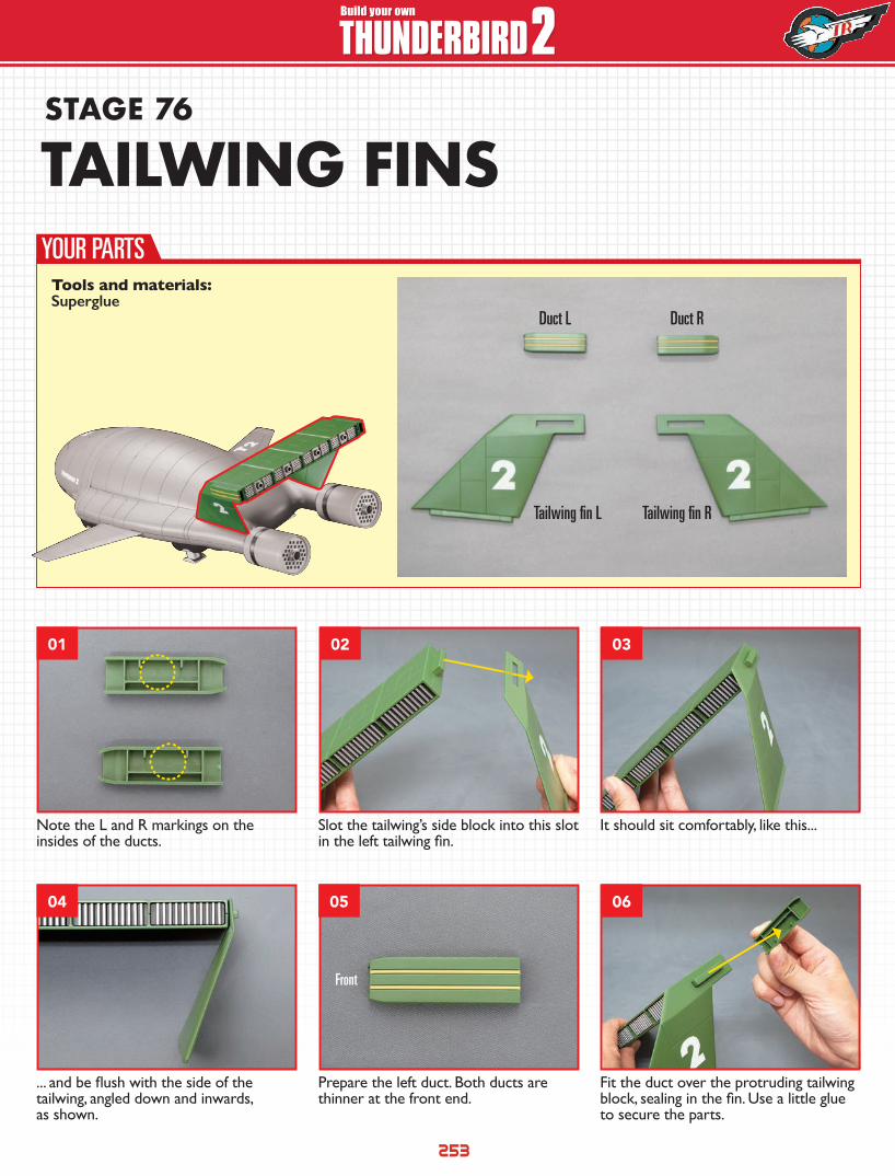
Note the L and R markings on the insides of the ducts.
Slot the tailwing’s side block into this slot in the left tailwing fin.
It should sit comfortably, like this...
... and be flush with the side of the tailwing, angled down and inwards, as shown.
Prepare the left duct. Both ducts are thinner at the front end.
Fit the duct over the protruding tailwing block, sealing in the fin. Use a little glue to secure the parts.
Front
YOUR PARTS
01
04
02
05
03
06
Tools and materials: Superglue
TAILWING FINS
Duct L
Tailwing fin L Tailwing fin R
Duct R

254
HOW TO BUILD HOW TO BUILDBuild your own
THUNDERBIRD 2
STAGE COMPLETE
Make sure the duct is flush with the side of the tailwing.
Repeat for the right fin. Again, its side block will locate it.
And the right duct will secure it, with a little glue to strengthen the hold.
The tailwing fins are now complete.
07
10
08
11
09
255
HOW TO BUILD HOW TO BUILDBuild your own
THUNDERBIRD 2STAGE 77
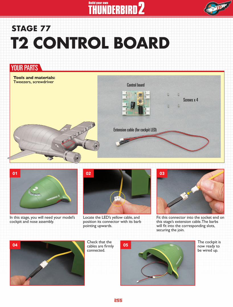
Check that the cables are firmly connected.
The cockpit is now ready to be wired up.
In this stage, you will need your model’s cockpit and nose assembly.
Locate the LED’s yellow cable, and position its connector with its barb pointing upwards.
Fit this connector into the socket end on this stage’s extension cable. The barbs will fit into the corresponding slots, securing the join.
YOUR PARTS
01
04 05
02 03
T2 CONTROL BOARD
Control board
Screws x 4
Extension cable (for cockpit LED)
Tools and materials: Tweezers, screwdriver
256
HOW TO BUILD HOW TO BUILDBuild your own
THUNDERBIRD 2
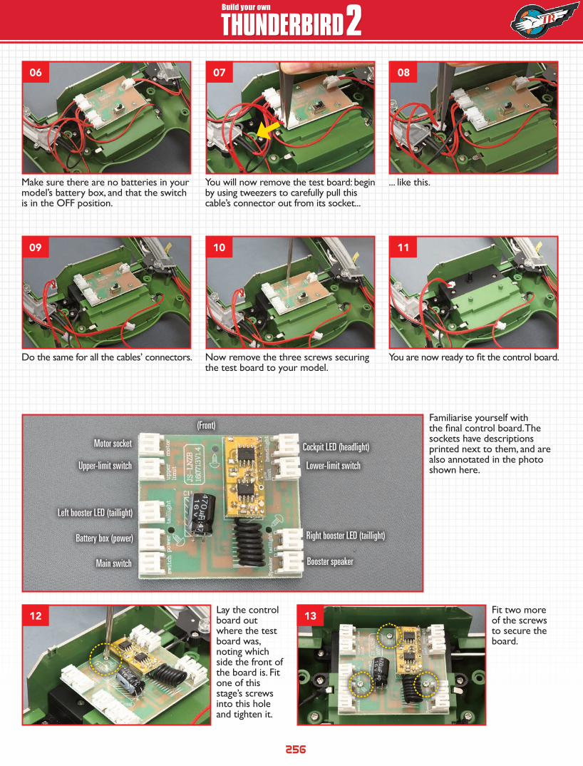
Make sure there are no batteries in your model’s battery box, and that the switch is in the OFF position.
Familiarise yourself with the final control board. The sockets have descriptions printed next to them, and are also annotated in the photo shown here.
Fit two more of the screws to secure the board.
Lay the control board out where the test board was, noting which side the front of the board is. Fit one of this stage’s screws into this hole and tighten it.
You will now remove the test board: begin by using tweezers to carefully pull this cable’s connector out from its socket...
... like this.
Do the same for all the cables’ connectors. Now remove the three screws securing the test board to your model.
You are now ready to fit the control board.
Motor socket
Upper-limit switch Lower-limit switch
Cockpit LED (headlight)
Battery box (power) Right booster LED (taillight)
Left booster LED (taillight)
Main switch Booster speaker
(Front)
06 07 08
09
12 13
10 11
257
HOW TO BUILD HOW TO BUILDBuild your own
THUNDERBIRD 2
STAGE COMPLETE
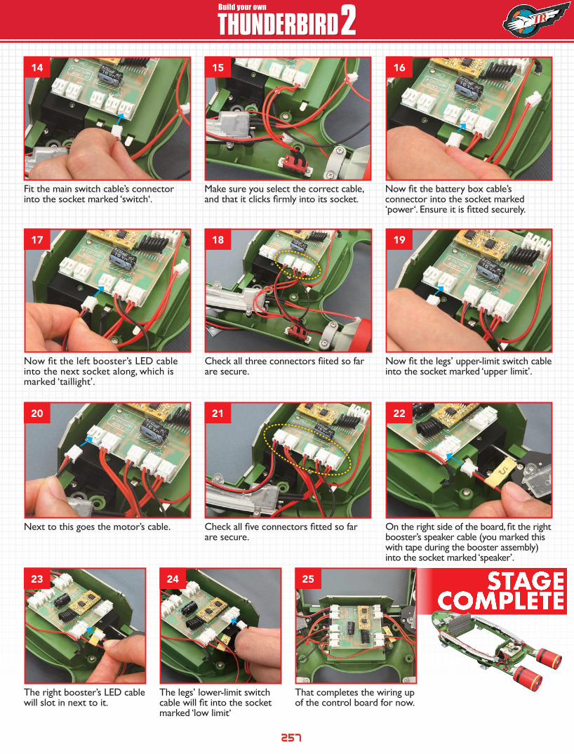
Check all three connectors fiited so far are secure.
Next to this goes the motor’s cable.
Now fit the legs’ upper-limit switch cable into the socket marked ‘upper limit’.
Fit the main switch cable’s connector into the socket marked ‘switch‘.
Now fit the battery box cable’s connector into the socket marked ‘power‘. Ensure it is fitted securely.
Make sure you select the correct cable, and that it clicks firmly into its socket.
Now fit the left booster’s LED cable into the next socket along, which is marked ‘taillight’.
On the right side of the board, fit the right booster’s speaker cable (you marked this with tape during the booster assembly) into the socket marked ‘speaker’.
The right booster’s LED cable will slot in next to it.
Check all five connectors fitted so far are secure.
The legs’ lower-limit switch cable will fit into the socket marked ‘low limit‘
That completes the wiring up of the control board for now.
14
17
20
23
15
18
21
16
19
22
24 25
258
HOW TO BUILD HOW TO BUILDBuild your own
THUNDERBIRD 2STAGE 78
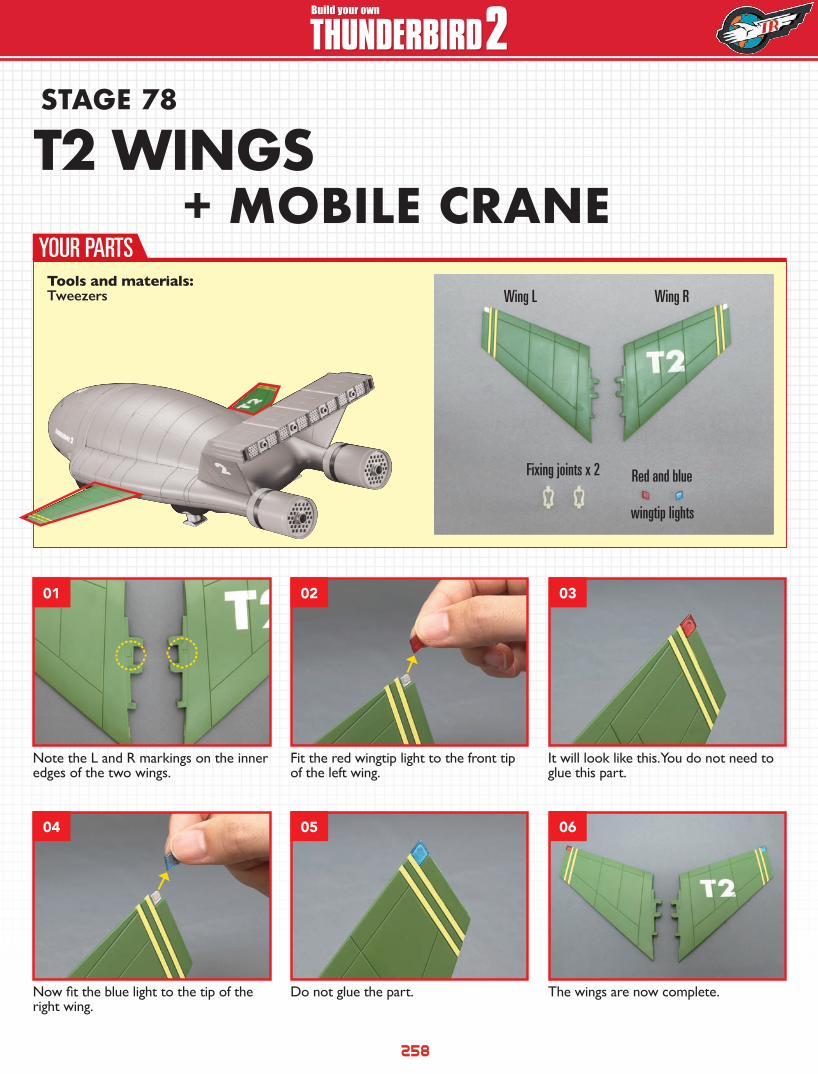
Note the L and R markings on the inner edges of the two wings.
Fit the red wingtip light to the front tip of the left wing.
It will look like this. You do not need to glue this part.
Now fit the blue light to the tip of the right wing.
Do not glue the part. The wings are now complete.
YOUR PARTS
01
04
02
05
03
06
T2 WINGS+ MOBILE CRANE
Wing L
Fixing joints x 2
wingtip lights
Red and blue
Wing RTools and materials: Tweezers
259
HOW TO BUILD HOW TO BUILDBuild your own
THUNDERBIRD 2
STAGE COMPLETE
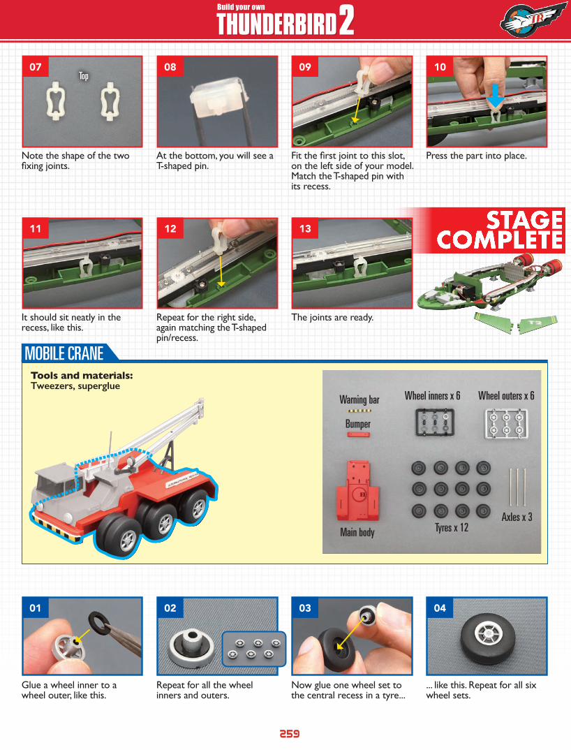
Glue a wheel inner to a wheel outer, like this.
Now glue one wheel set to the central recess in a tyre...
Repeat for all the wheel inners and outers.
... like this. Repeat for all six wheel sets.
Note the shape of the two fixing joints.
It should sit neatly in the recess, like this.
At the bottom, you will see a T-shaped pin.
Repeat for the right side, again matching the T-shaped pin/recess.
Fit the first joint to this slot, on the left side of your model. Match the T-shaped pin with its recess.
The joints are ready.
Press the part into place.
Top
01
07
11
02
08
12
03
09
13
04
10
MOBILE CRANE
Warning bar Wheel inners x 6 Wheel outers x 6
Tyres x 12Axles x 3
Bumper
Main body
Tools and materials: Tweezers, superglue
260
HOW TO BUILD HOW TO BUILDBuild your own
THUNDERBIRD 2
STAGE COMPLETE
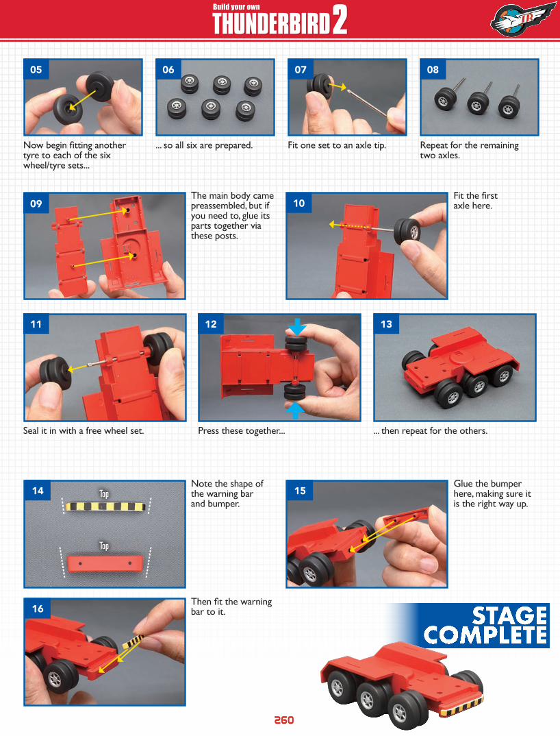
The main body came preassembled, but if you need to, glue its parts together via these posts.
Note the shape of the warning bar and bumper.
Seal it in with a free wheel set.
Then fit the warning bar to it.
Fit the first axle here.
Glue the bumper here, making sure it is the right way up.
Press these together... ... then repeat for the others.
Now begin fitting another tyre to each of the six wheel/tyre sets...
Fit one set to an axle tip.... so all six are prepared. Repeat for the remaining two axles.
Top
Top
09
11 12 13
1514
16
05 06 07 0508
10
261
HOW TO BUILD HOW TO BUILDBuild your own
THUNDERBIRD 2STAGE 79
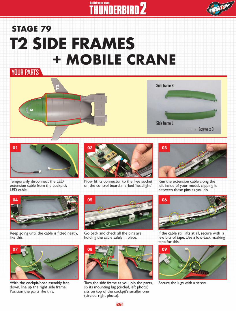
Temporarily disconnect the LED extension cable from the cockpit’s LED cable.
Now fit its connector to the free socket on the control board, marked ‘headlight’.
Run the extension cable along the left inside of your model, clipping it between these pins as you do.
With the cockpit/nose asembly face down, line up the right side frame. Position the parts like this.
Turn the side frame as you join the parts, so its mounting lug (circled, left photo) sits on top of the cockpit’s smaller one (circled, right photo).
Secure the lugs with a screw.
Keep going until the cable is fitted neatly, like this.
Go back and check all the pins are holding the cable safely in place.
If the cable still lifts at all, secure with a few bits of tape. Use a low-tack masking tape for this.
YOUR PARTS
01
04
07
02
05
08
03
06
09
T2 SIDE FRAMES+ MOBILE CRANE
Side frame LScrews x 3
Side frame R
262
HOW TO BUILD HOW TO BUILDBuild your own
THUNDERBIRD 2STAGE
COMPLETE
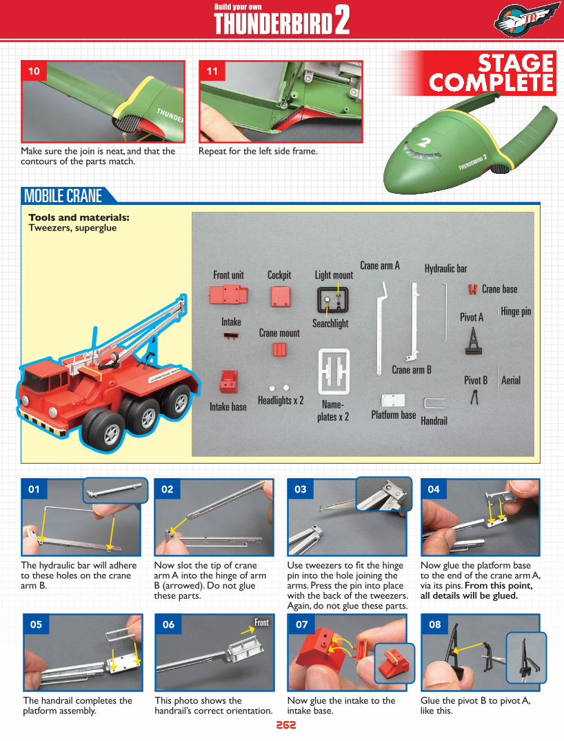
Make sure the join is neat, and that the contours of the parts match.
Repeat for the left side frame.
The hydraulic bar will adhere to these holes on the crane arm B.
Now glue the platform base to the end of the crane arm A, via its pins. From this point, all details will be glued.
Now slot the tip of crane arm A into the hinge of arm B (arrowed). Do not glue these parts.
Use tweezers to fit the hinge pin into the hole joining the arms. Press the pin into place with the back of the tweezers. Again, do not glue these parts.
The handrail completes the platform assembly.
This photo shows the handrail’s correct orientation.
Now glue the intake to the intake base.
Glue the pivot B to pivot A, like this.
Front
10 11
01
05
02
06
03
07
04
08
Front unit Cockpit
Searchlight
Light mountCrane arm A Hydraulic bar
Crane base
Pivot A Hinge pin
AerialPivot BCrane arm B
Platform base Handrail
Crane mount
Headlights x 2 Name-plates x 2
Intake
Intake base
Tools and materials: Tweezers, superglue
MOBILE CRANE
263
HOW TO BUILD HOW TO BUILDBuild your own
THUNDERBIRD 2
STAGE COMPLETE
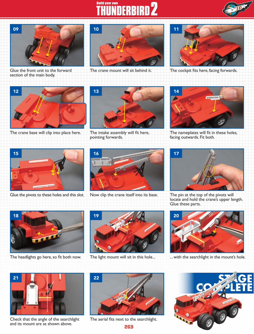
The crane mount will sit behind it.Glue the front unit to the forward section of the main body.
The cockpit fits here, facing forwards.
The intake assembly will fit here, pointing forwards.
The crane base will clip into place here. The nameplates will fit in these holes, facing outwards. Fit both.
The light mount will sit in this hole...The headlights go here, so fit both now. ... with the searchlight in the mount’s hole.
Now clip the crane itself into its base.Glue the pivots to these holes and this slot. The pin at the top of the pivots will locate and hold the crane’s upper length. Glue these parts.
The aerial fits next to the searchlight.Check that the angle of the searchlight and its mount are as shown above.
09
15
12
18
21
10
16
13
19
22
11
17
14
20
264
HOW TO BUILD HOW TO BUILDBuild your own
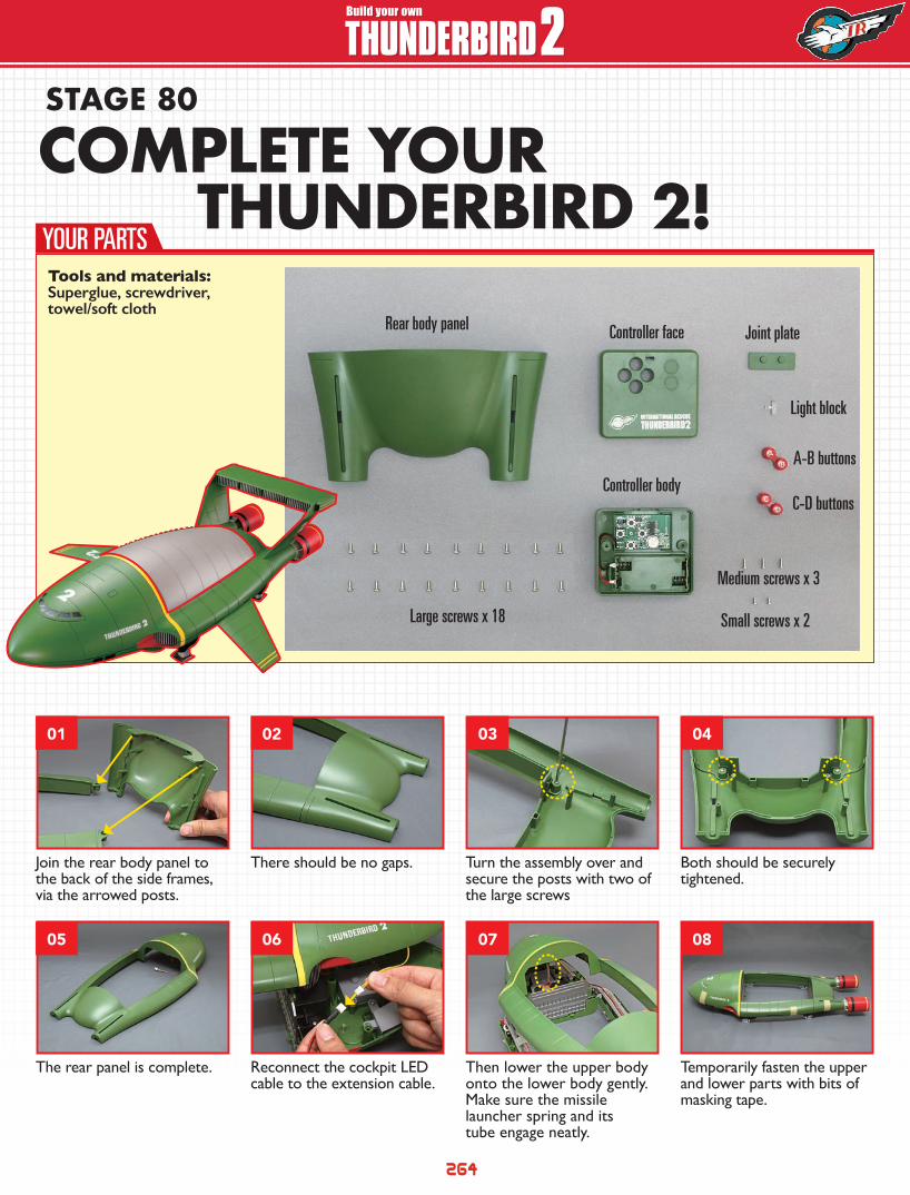
THUNDERBIRD 2STAGE 80
Join the rear body panel to the back of the side frames, via the arrowed posts.
Turn the assembly over and secure the posts with two of the large screws
There should be no gaps. Both should be securely tightened.
The rear panel is complete. Then lower the upper body onto the lower body gently. Make sure the missile launcher spring and its tube engage neatly.
Reconnect the cockpit LED cable to the extension cable.
Temporarily fasten the upper and lower parts with bits of masking tape.
YOUR PARTS
01
05
02
06
03
07
04
08
COMPLETE YOUR THUNDERBIRD 2!
Rear body panel Controller face Joint plate
Light block
A-B buttons
C-D buttons
Medium screws x 3
Small screws x 2
Controller body
Large screws x 18
Tools and materials: Superglue, screwdriver, towel/soft cloth
265
HOW TO BUILD HOW TO BUILDBuild your own
THUNDERBIRD 2
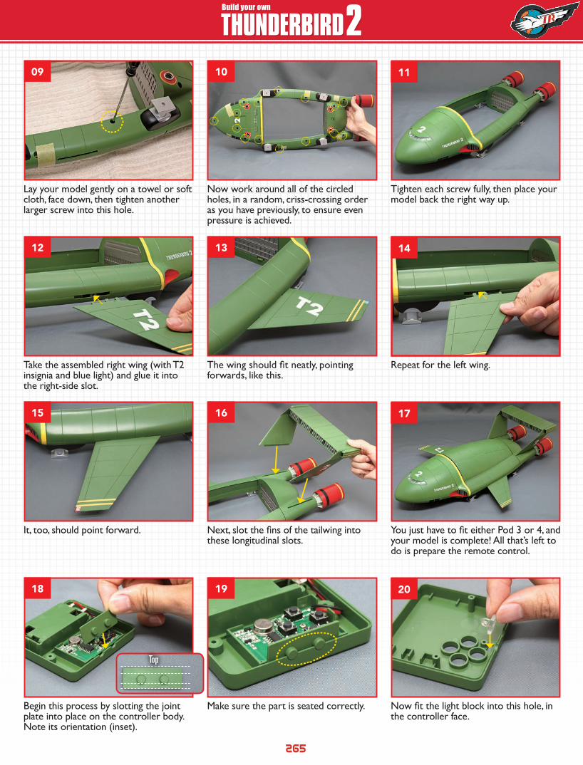
Lay your model gently on a towel or soft cloth, face down, then tighten another larger screw into this hole.
Now work around all of the circled holes, in a random, criss-crossing order as you have previously, to ensure even pressure is achieved.
Tighten each screw fully, then place your model back the right way up.
Take the assembled right wing (with T2 insignia and blue light) and glue it into the right-side slot.
The wing should fit neatly, pointing forwards, like this.
Repeat for the left wing.
Begin this process by slotting the joint plate into place on the controller body. Note its orientation (inset).
Make sure the part is seated correctly. Now fit the light block into this hole, in the controller face.
It, too, should point forward. Next, slot the fins of the tailwing into these longitudinal slots.
You just have to fit either Pod 3 or 4, and your model is complete! All that’s left to do is prepare the remote control.
Top
09
12
15
18
10
13
16
19
11
14
17
20
266
HOW TO BUILD HOW TO BUILDBuild your own
THUNDERBIRD 2
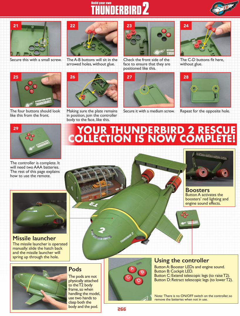
YOUR THUNDERBIRD 2 RESCUE COLLECTION IS NOW COMPLETE!
Pods
Boosters
Secure this with a small screw. Check the front side of the face to ensure that they are positioned like this.
The A-B buttons will sit in the arrowed holes, without glue.
The C-D buttons fit here, without glue.
The four buttons should look like this from the front.
Secure it with a medium screw.Making sure the plate remains in position, join the controller body to the face, like this.
Repeat for the opposite hole.
The controller is complete. It will need two AAA batteries. The rest of this page explains how to use the remote.
The pods are not physically attached to the T2 body frame, so when handling the model, use two hands to clasp both the body and the pod.
Button A activates the boosters’ red lighting and engine sound effects.
Using the controllerButton A: Booster LEDs and engine sound.Button B: Cockpit LED.Button C: Extend telescopic legs (to raise T2).Button D: Retract telescopic legs (to lower T2).
Note: There is no ON/OFF switch on the controller, so remove the batteries when not in use.
Missile launcherThe missile launcher is operated manually: slide the hatch back and the missile launcher will spring up through the hole.
21
25
29
22
26
23
27
24
28
HOW TO BUILD HOW TO BUILDBuild your own
THUNDERBIRD 2
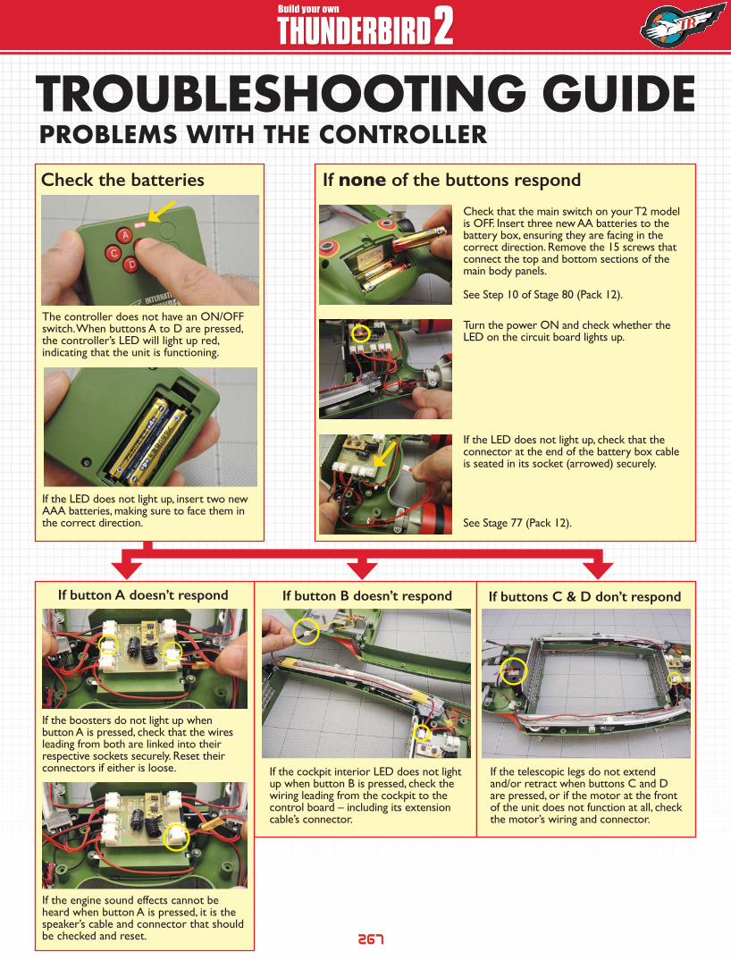
The controller does not have an ON/OFF switch. When buttons A to D are pressed, the controller’s LED will light up red, indicating that the unit is functioning.
If the boosters do not light up when button A is pressed, check that the wires leading from both are linked into their respective sockets securely. Reset their connectors if either is loose. If the cockpit interior LED does not light
up when button B is pressed, check the wiring leading from the cockpit to the control board – including its extension cable’s connector.
If the telescopic legs do not extend and/or retract when buttons C and D are pressed, or if the motor at the front of the unit does not function at all, check the motor’s wiring and connector.
If the engine sound effects cannot be heard when button A is pressed, it is the speaker’s cable and connector that should be checked and reset.
If the LED does not light up, insert two new AAA batteries, making sure to face them in the correct direction.
Check that the main switch on your T2 model is OFF. Insert three new AA batteries to the battery box, ensuring they are facing in the correct direction. Remove the 15 screws that connect the top and bottom sections of the main body panels.
See Step 10 of Stage 80 (Pack 12).
Turn the power ON and check whether the LED on the circuit board lights up.
If the LED does not light up, check that the connector at the end of the battery box cable is seated in its socket (arrowed) securely.
See Stage 77 (Pack 12).
TROUBLESHOOTING GUIDEPROBLEMS WITH THE CONTROLLERCheck the batteries If none of the buttons respond
If button A doesn’t respond If button B doesn’t respond If buttons C & D don’t respond
267
268
HOW TO BUILD HOW TO BUILDBuild your own
THUNDERBIRD 2
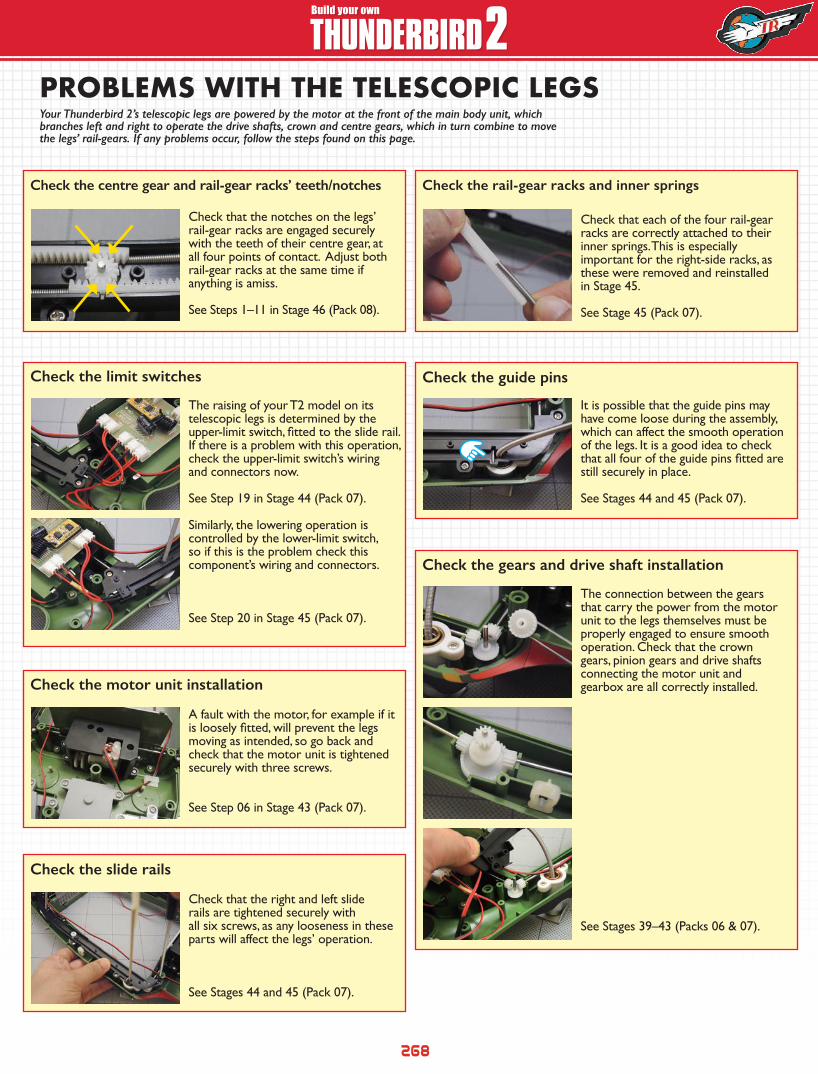
Check that the notches on the legs’ rail-gear racks are engaged securely with the teeth of their centre gear, at all four points of contact. Adjust both rail-gear racks at the same time if anything is amiss. See Steps 1–11 in Stage 46 (Pack 08).
Check that each of the four rail-gear racks are correctly attached to their inner springs. This is especially important for the right-side racks, as these were removed and reinstalled in Stage 45.
See Stage 45 (Pack 07).
The raising of your T2 model on its telescopic legs is determined by the upper-limit switch, fitted to the slide rail. If there is a problem with this operation, check the upper-limit switch’s wiring and connectors now.
See Step 19 in Stage 44 (Pack 07).
It is possible that the guide pins may have come loose during the assembly, which can affect the smooth operation of the legs. It is a good idea to check that all four of the guide pins fitted are still securely in place.
See Stages 44 and 45 (Pack 07).
Similarly, the lowering operation is controlled by the lower-limit switch, so if this is the problem check this component’s wiring and connectors.
See Step 20 in Stage 45 (Pack 07).
The connection between the gears that carry the power from the motor unit to the legs themselves must be properly engaged to ensure smooth operation. Check that the crown gears, pinion gears and drive shafts connecting the motor unit and gearbox are all correctly installed.
See Stages 39–43 (Packs 06 & 07).
A fault with the motor, for example if it is loosely fitted, will prevent the legs moving as intended, so go back and check that the motor unit is tightened securely with three screws.
See Step 06 in Stage 43 (Pack 07).
Check that the right and left slide rails are tightened securely with all six screws, as any looseness in these parts will affect the legs’ operation.
See Stages 44 and 45 (Pack 07).
Check the centre gear and rail-gear racks’ teeth/notches Check the rail-gear racks and inner springs
Check the limit switches Check the guide pins
Check the gears and drive shaft installation
Check the motor unit installation
Check the slide rails
Your Thunderbird 2’s telescopic legs are powered by the motor at the front of the main body unit, which branches left and right to operate the drive shafts, crown and centre gears, which in turn combine to move the legs’ rail-gears. If any problems occur, follow the steps found on this page.
PROBLEMS WITH THE TELESCOPIC LEGS