Embed Size (px)
Citation preview
Building High Availability System on
Fujitsu SPARC M12 and Fujitsu M10/
SPARC M10 Servers
(System configuration)
April. 2017
Rev2.0
Fujitsu LIMITED

Building High Availability System on Fujitsu SPARC M12 and Fujitsu M10 /SPARC M10 Servers (System configuration)
Copyright 2017 FUJITSU LIMITED i
Preface
• This document describes the high availability system configuration procedure with Physical
Partition Dynamic Reconfiguration (PPAR DR) supported by Fujitsu SPARC M12 and Fujitsu
M10 server. See also, Building High Availability System on Fujitsu SPARC M12 and Fujitsu
M10 Servers (maintenance procedure).
• The result of each commands described in this document may be different in each platform
and software version.
• This document describes the procedure with Fujitsu SPARC M12 and Fujitsu M10 Systems,
Oracle VM Server for SPARC 3.3 and Oracle Solaris11.3.
• For further details about PPAR DR, see following manuals.
http://www.fujitsu.com/global/products/computing/servers/unix/sparc/downloads/manuals/
Fujitsu SPARC M12 and Fujitsu M10/SPARC M10 System Operation and Administration
Guide.
Fujitsu SPARC M12 and Fujitsu M10/SPARC M10 Domain Configuration Guide.
Fujitsu SPARC M12 and Fujitsu M10/SPARC M10 XSCF Reference Manual.
Conditions of use for this document
About copyright, trademark right, and other intellectual property rights.
This contents (texts, graphics, voices and so on) are protected by copyright, trademark right,
and other intellectual property rights. This contents allow to print-out and download within an
individual activity. But for other purposes (redistribute the contents in his/her website or in any
servers), you must need the authorization of our company or the right holder.
Disclaimer
Fujitsu limited, and/or its affiliates make no representations or warranties of any kind regarding
this contents which are all provided as is, and all express or implied conditions. This contents
are subject to change or excise without notice.
Building High Availability System on Fujitsu SPARC M12 and Fujitsu M10 /SPARC M10 Servers (System configuration)
Copyright 2017 FUJITSU LIMITED ii
About trademarks
UNIX is a registered trademark of The Open Group
SPARC Enterprise, SPARC64, SPARC64 logo and all SPARC trademarks are trademarks or
registered trademarks of SPARC International, Inc. in the United States and other countries
and used under license.
Oracle and Java are registered trademarks of Oracle and/or its affiliates.
Other names may be trademarks of their respective owners.
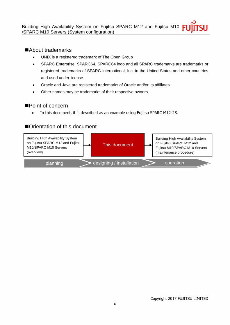
Point of concern
In this document, it is described as an example using Fujitsu SPARC M12-2S.
Orientation of this document
operation designing / installation planning
This document
Building High Availability System
on Fujitsu SPARC M12 and
Fujitsu M10/SPARC M10 Servers
(maintenance procedure)
Building High Availability System
on Fujitsu SPARC M12 and Fujitsu
M10/SPARC M10 Servers
(overview)
Building High Availability System on Fujitsu SPARC M12 and Fujitsu M10 /SPARC M10 Servers (System configuration)
Copyright 2017 FUJITSU LIMITED iii
Contents
1. Preface .................................................................................................. 1
1.1 Overview of the BB HA ............................................................................................... 1
1.2 Overview of PPAR DR ................................................................................................ 1
1.2.1 Configuration and Resource Planning for PPAR DR Board Delete .................................. 2
1.2.2 vcpu Remapping Concept ............................................................................................... 3
1.2.3 Memory Remapping Concept .......................................................................................... 4
1.3 Requisite of BB HA ..................................................................................................... 5
1.4 Known issues of configuring BB HA system. .............................................................. 7
1.5 System configuration described in this document. ...................................................... 8
1.5.1 Configuration of control domain only (traditional type) ..................................................... 9
1.5.2 Configuration of control domain and multiple root domains (consolidation type) ............ 12
1.5.3 Configuration of control domain and multiple guest domains (high consolidation type) .. 16
1.6 The flow of system configuration .............................................................................. 20
1.6.1 The flow of configuration of traditional type .................................................................... 20
1.6.2 The flow of configuration of consolidation type .............................................................. 21
1.6.3 The flow of configuration of high consolidation type ....................................................... 22
2. Setup the physical partition configuration ............................................. 23
2.1 Log in to the master XSCF ....................................................................................... 23
2.2 Create the physical partition configuration information ............................................. 23
2.3 Assign a system board to a physical partition ........................................................... 23
2.4 Register the CPU Activation key to assign CPU core resources............................... 24
2.5 Reset the time correction in XSCF ............................................................................ 26
2.6 Check the setting of the physical partition ................................................................ 26
2.7 Power on the physical partition. ................................................................................ 26
2.8 Connect the console to the physical partition. .......................................................... 27
3. Configure of the traditional type ........................................................... 28
3.1 Install Oracle Solaris and Oracle VM Server for SPARC .......................................... 28
3.2 Configure the control domain (global zone) .............................................................. 28
3.3 Configure the Oracle Solaris zone ............................................................................ 35
3.3.1 Create the non-global zone ........................................................................................... 35
Building High Availability System on Fujitsu SPARC M12 and Fujitsu M10 /SPARC M10 Servers (System configuration)
Copyright 2017 FUJITSU LIMITED iv
3.3.2 Install Oracle Solaris ..................................................................................................... 36
3.3.3 Establish a system configuration of non-global zone ..................................................... 37
3.3.4 Check the status of the non-global zone ........................................................................ 38
4. Configure of the consolidation type ...................................................... 39
4.1 Install Oracle Solaris and Oracle VM Server for SPARC. ......................................... 39
4.2 Configure the logical domain(s) ................................................................................ 39
4.3 Configure the root domain ........................................................................................ 49
4.3.1 Install Oracle Solaris ..................................................................................................... 49
4.3.2 Establish a redundant configuration of the root domain. ................................................ 50
5. Configure of the high consolidation type .............................................. 53
5.1 Install Oracle Solaris and Oracle VM Server for SPARC .......................................... 53
5.2 Configure the logical domain(s) ................................................................................ 53
5.3 Configure the guest domain(s).................................................................................. 61
5.3.1 Install Oracle Solaris ..................................................................................................... 61
6. Setup the Oracle VM for SPARC properties and save the configuration
information ................................................................................................... 63
6.1 Save the configured Oracle Solaris zone .................................................................. 63
6.2 Setup the Oracle VM for SPARC properties and save the configuration .................. 64
6.2.1 Enable recovery mode................................................................................................... 64
6.2.2 Enable auto-reboot after collecting a Hypervisor dump file ............................................ 64
6.2.3 Save the configured local domain configuration information to the XSCF ...................... 65
6.2.4 Backup the configured logical domain configuration information to an XML file ............. 66
Appendix.A. PPAR DR deleteboard Best Practice ....................................... 67
A.1 Best practice configuration for PPAR DR deleteboard ............................................. 67
Revision history ........................................................................................... 72
Building High Availability System on Fujitsu SPARC M12 and Fujitsu M10 /SPARC M10 Servers (System configuration)
Copyright 2017 FUJITSU LIMITED 1
1. Preface
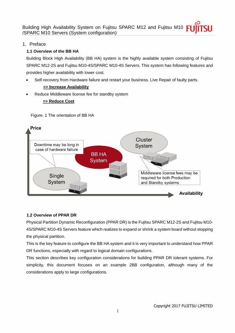
1.1 Overview of the BB HA
Building Block High Availability (BB HA) system is the highly available system consisting of Fujitsu
SPARC M12-2S and Fujitsu M10-4S/SPARC M10-4S Servers. This system has following features and
provides higher availability with lower cost.
Self-recovery from Hardware failure and restart your business. Live Repair of faulty parts.
=> Increase Availability
Reduce Middleware license fee for standby system
=> Reduce Cost
Figure. 1 The orientation of BB HA
1.2 Overview of PPAR DR
Physical Partition Dynamic Reconfiguration (PPAR DR) is the Fujitsu SPARC M12-2S and Fujitsu M10-
4S/SPARC M10-4S Servers feature which realizes to expand or shrink a system board without stopping
the physical partition.
This is the key feature to configure the BB HA system and it is very important to understand how PPAR
DR functions, especially with regard to logical domain configurations.
This section describes key configuration considerations for building PPAR DR tolerant systems. For
simplicity, this document focuses on an example 2BB configuration, although many of the
considerations apply to large configurations.
Building High Availability System on Fujitsu SPARC M12 and Fujitsu M10 /SPARC M10 Servers (System configuration)
Copyright 2017 FUJITSU LIMITED 2
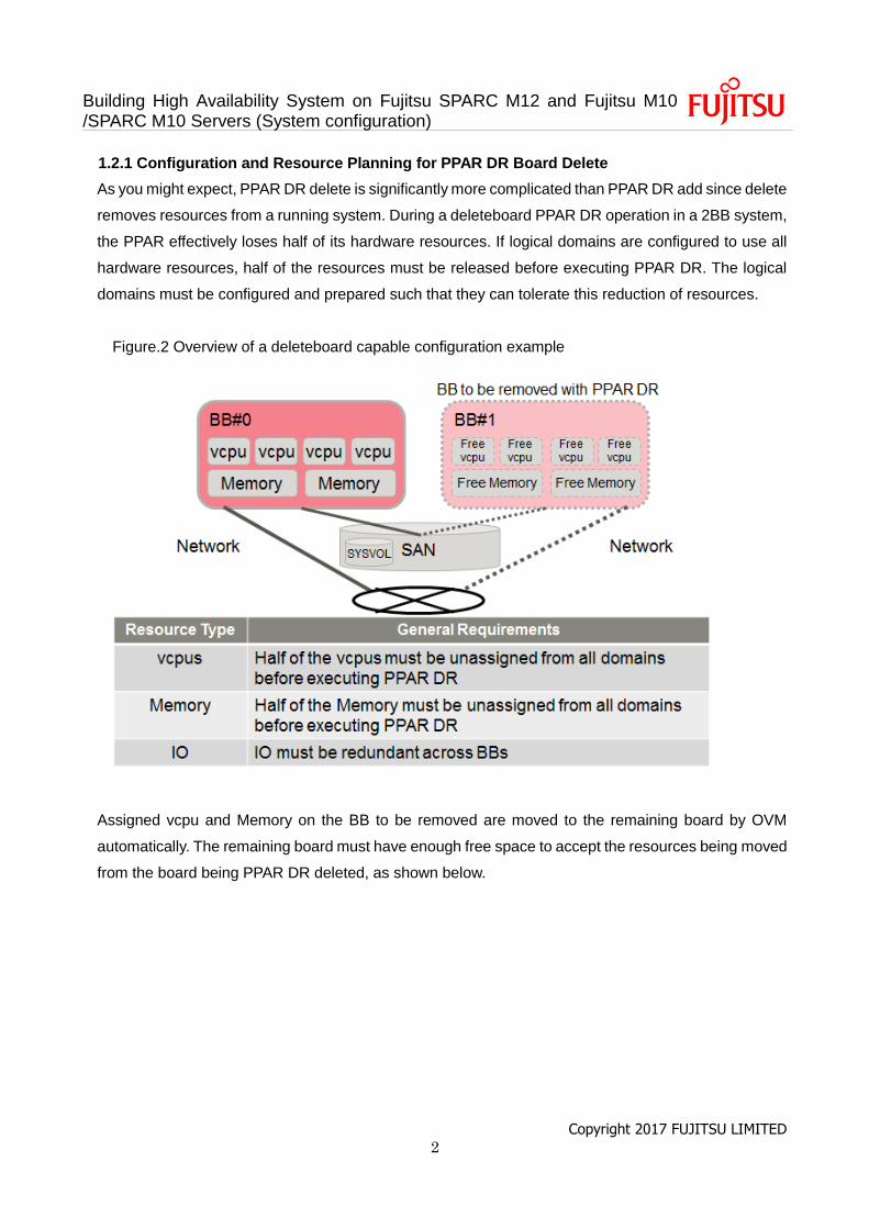
1.2.1 Configuration and Resource Planning for PPAR DR Board Delete
As you might expect, PPAR DR delete is significantly more complicated than PPAR DR add since delete
removes resources from a running system. During a deleteboard PPAR DR operation in a 2BB system,
the PPAR effectively loses half of its hardware resources. If logical domains are configured to use all
hardware resources, half of the resources must be released before executing PPAR DR. The logical
domains must be configured and prepared such that they can tolerate this reduction of resources.
Figure.2 Overview of a deleteboard capable configuration example
Assigned vcpu and Memory on the BB to be removed are moved to the remaining board by OVM
automatically. The remaining board must have enough free space to accept the resources being moved
from the board being PPAR DR deleted, as shown below.
Building High Availability System on Fujitsu SPARC M12 and Fujitsu M10 /SPARC M10 Servers (System configuration)
Copyright 2017 FUJITSU LIMITED 3
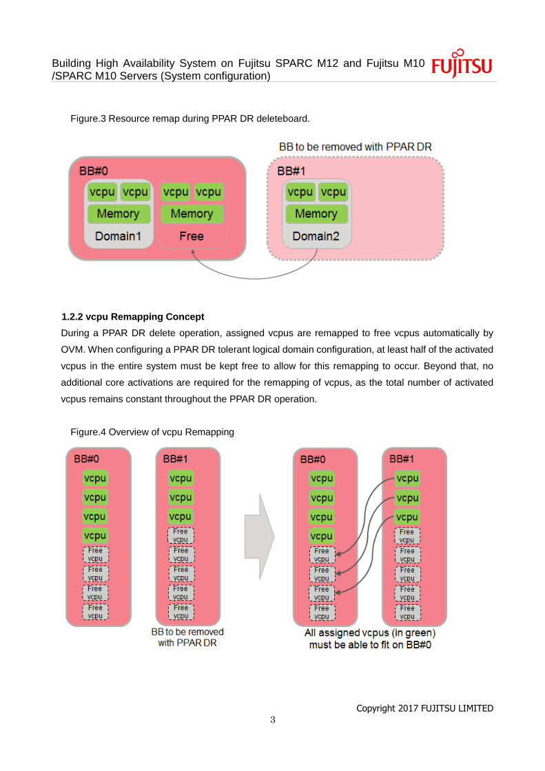
Figure.3 Resource remap during PPAR DR deleteboard.
1.2.2 vcpu Remapping Concept
During a PPAR DR delete operation, assigned vcpus are remapped to free vcpus automatically by
OVM. When configuring a PPAR DR tolerant logical domain configuration, at least half of the activated
vcpus in the entire system must be kept free to allow for this remapping to occur. Beyond that, no
additional core activations are required for the remapping of vcpus, as the total number of activated
vcpus remains constant throughout the PPAR DR operation.
Figure.4 Overview of vcpu Remapping
Building High Availability System on Fujitsu SPARC M12 and Fujitsu M10 /SPARC M10 Servers (System configuration)
Copyright 2017 FUJITSU LIMITED 4
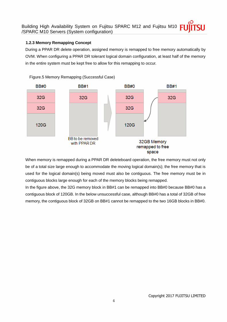
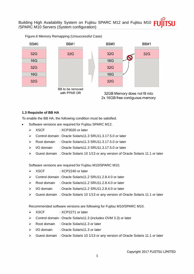
1.2.3 Memory Remapping Concept
During a PPAR DR delete operation, assigned memory is remapped to free memory automatically by
OVM. When configuring a PPAR DR tolerant logical domain configuration, at least half of the memory
in the entire system must be kept free to allow for this remapping to occur.
Figure.5 Memory Remapping (Successful Case)
When memory is remapped during a PPAR DR deleteboard operation, the free memory must not only
be of a total size large enough to accommodate the moving logical domain(s); the free memory that is
used for the logical domain(s) being moved must also be contiguous. The free memory must be in
contiguous blocks large enough for each of the memory blocks being remapped.
In the figure above, the 32G memory block in BB#1 can be remapped into BB#0 because BB#0 has a
contiguous block of 120GB. In the below unsuccessful case, although BB#0 has a total of 32GB of free
memory, the contiguous block of 32GB on BB#1 cannot be remapped to the two 16GB blocks in BB#0.
Building High Availability System on Fujitsu SPARC M12 and Fujitsu M10 /SPARC M10 Servers (System configuration)
Copyright 2017 FUJITSU LIMITED 5
Figure.6 Memory Remapping (Unsuccessful Case)
1.3 Requisite of BB HA
To enable the BB HA, the following condition must be satisfied.
Software versions are required for Fujitsu SPARC M12.
XSCF : XCP3020 or later
Control domain : Oracle Solaris11.3 SRU11.3.17.5.0 or later
Root domain : Oracle Solaris11.3 SRU11.3.17.5.0 or later
I/O domain : Oracle Solaris11.3 SRU11.3.17.5.0 or later
Guest domain : Oracle Solaris 10 1/13 or any version of Oracle Solaris 11.1 or later
Software versions are required for Fujitsu M10/SPARC M10.
XSCF : XCP2240 or later
Control domain : Oracle Solaris11.2 SRU11.2.8.4.0 or later
Root domain : Oracle Solaris11.2 SRU11.2.8.4.0 or later
I/O domain : Oracle Solaris11.2 SRU11.2.8.4.0 or later
Guest domain : Oracle Solaris 10 1/13 or any version of Oracle Solaris 11.1 or later
Recommended software versions are following for Fujitsu M10/SPARC M10.
XSCF : XCP2271 or later
Control domain : Oracle Solaris11.3 (includes OVM 3.3) or later
Root domain : Oracle Solaris11.3 or later
I/O domain : Oracle Solaris11.3 or later
Guest domain : Oracle Solaris 10 1/13 or any version of Oracle Solaris 11.1 or later
Building High Availability System on Fujitsu SPARC M12 and Fujitsu M10 /SPARC M10 Servers (System configuration)
Copyright 2017 FUJITSU LIMITED 6
Reserve a half of CPU/Memory resources of the physical partition to keep the resource of each
domains after a system board is removed due to some faults.
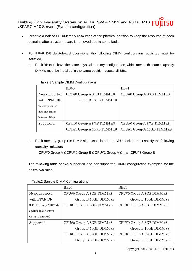
For PPAR DR deleteboard operations, the following DIMM configuration requisites must be
satisfied.
a. Each BB must have the same physical memory configuration, which means the same capacity
DIMMs must be installed in the same position across all BBs.
Table.1 Sample DIMM Configurations
BB#0 BB#1
Non-supported
with PPAR DR
(memory config
does not match
between BBs)
CPU#0 Group A 8GB DIMM x8
Group B 16GB DIMM x8
CPU#0 Group A 8GB DIMM x8
Supported CPU#0 Group A 8GB DIMM x8
CPU#1 Group A 16GB DIMM x8
CPU#0 Group A 8GB DIMM x8
CPU#1 Group A 16GB DIMM x8
b. Each memory group (16 DIMM slots associated to a CPU socket) must satisfy the following
capacity limitation:
CPU#0 Group A ≤ CPU#0 Group B ≤ CPU#1 Group A ≤ ... ≤ CPU#3 Group B
The following table shows supported and non-supported DIMM configuration examples for the
above two rules.
Table.2 Sample DIMM Configurations
BB#0 BB#1
Non-supported
with PPAR DR
(CPU#1 Group A DIMMs
smaller than CPU#0
Group B DIMMs)
CPU#0 Group A 8GB DIMM x8
Group B 16GB DIMM x8
CPU#1 Group A 8GB DIMM x8
CPU#0 Group A 8GB DIMM x8
Group B 16GB DIMM x8
CPU#1 Group A 8GB DIMM x8
Supported CPU#0 Group A 8GB DIMM x8
Group B 16GB DIMM x8
CPU#1 Group A 32GB DIMM x8
Group B 32GB DIMM x8
CPU#0 Group A 8GB DIMM x8
Group B 16GB DIMM x8
CPU#1 Group A 32GB DIMM x8
Group B 32GB DIMM x8
Building High Availability System on Fujitsu SPARC M12 and Fujitsu M10 /SPARC M10 Servers (System configuration)
Copyright 2017 FUJITSU LIMITED 7
Create a redundant configuration by connecting I/O devices under the root complex of each system
board to the system volume I/O devices and the network of each domains.
1.4 Known issues of configuring BB HA system.
The following lists known issues related to configure the BB HA system.
Before configuring your BB HA system, please confirm if any of the conditions shown below are present.
If they are, follow the guidance shown below to obtain the fix or workaround.
1. Internal SAS disk which is used as a boot disk cannot be detached
Bug ID: 20646928
Bug Description: Cannot delete BB by physical DR with built-in disks in ZFS mirror configurations.
(Note: This issue is not directly related to ZFS mirror. BBs with boot disks, regardless of ZFS mirror
usage, cannot be detached due to this issue.)
Condition: Solaris 11.2 SRU8.4 or later is used, internal SAS disk(s) or 6G SAS PCIe card(s) is/are
used, and the deleteboard command is used to remove a BB that contains the last/current boot disk
path.
PPAR DR Operation Condition: deleteboard only
Symptom: An mpt_sas issue exists in SRU8 and later that prevents detaching disks dynamically.
When internal SAS disks are mirrored across multiple BBs, deleteboard always fails in the remove boot
disk step, due to disk busy.
Error Message:
XSCF> deleteboard -c disconnect -m unbind=resource 00-0
PSB#00-0 will be unconfigured from PPAR immediately. Continue?[y|n] :y
All domains are temporarily suspended, proceed?[y|n] :y
Start unconfigure preparation of PSB. [1200sec]
0end
Unconfigure preparation of PSB has completed.
Start unconfiguring PSB from PPAR. [7200sec]
0..../
The removal of PCIE0 from the domain primary failed.
Error message from svc:/ldoms/agents in domain primary:
ERROR: devices or resources are busy.
end
PSB#00-0 could not be unconfigured from PPAR-ID 0 due to operating system or Logical Domains
Manager error.
Building High Availability System on Fujitsu SPARC M12 and Fujitsu M10 /SPARC M10 Servers (System configuration)
Copyright 2017 FUJITSU LIMITED 8
Fix: Apply Oracle Solaris11.3 SRU5.6 or later.
Workaround: Do not use internal disks as boot disks, stop and unbind the domain, or to detach internal
boot disks, use delayed reconfiguration.
2. ZFS Mirrored disk cannot be detached by PPAR DR
Bug ID: 20896210
Bug Description: Panic in vdev_disk_io_start when trying to write to a DEGRADED device
(Note: This issue can also occur when cfgadm is used to unconfigure a ZFS mirrored disk.)
Condition: Solaris 11.2 SRU8 through SRU10. When disks are ZFS mirrored, this issue happens with
both internal and external disks.
PPAR DR Operation Condition: deleteboard only
Symptom: When disks are ZFS mirrored across multiple BB, deleteboard always fails due to disk busy.
Error Message:
XSCF> deleteboard -c disconnect -m unbind=resource 00-0
PSB#00-0 will be unconfigured from PPAR immediately. Continue?[y|n] :y
All domains are temporarily suspended, proceed?[y|n] :y
Start unconfigure preparation of PSB. [1200sec]
0
end
Unconfigure preparation of PSB has completed.
Start unconfiguring PSB from PPAR. [7200sec]
0....
The removal of PCIE0 from the domain primary failed.
Error message from svc:/ldoms/agents in domain primary:
ERROR: devices or resources are busy.
end
Fix: Apply Oracle Solaris11.2 SRU11.5 or later.
Workaround: Unconfigure the ZFS mirror before executing a PPAR DR deleteboard operation.
1.5 System configuration described in this document.
This chapter explains the environment of BB HA by three types in each paragraph as follows. Please
refer to 'Building a High Availability System on Fujitsu SPARC M12 and Fujitsu M10/SPARC M10 Server
(Overview)' for the feature of each environment. A physical partition in each environment has 2BBs.
1.5.1 Configuration of control domain only (traditional type)
1.5.2 Configuration of control domain and multiple root domains (consolidation type)
Building High Availability System on Fujitsu SPARC M12 and Fujitsu M10 /SPARC M10 Servers (System configuration)
Copyright 2017 FUJITSU LIMITED 9
1.5.3 Configuration of control domain and multiple guest domains (high consolidation type)
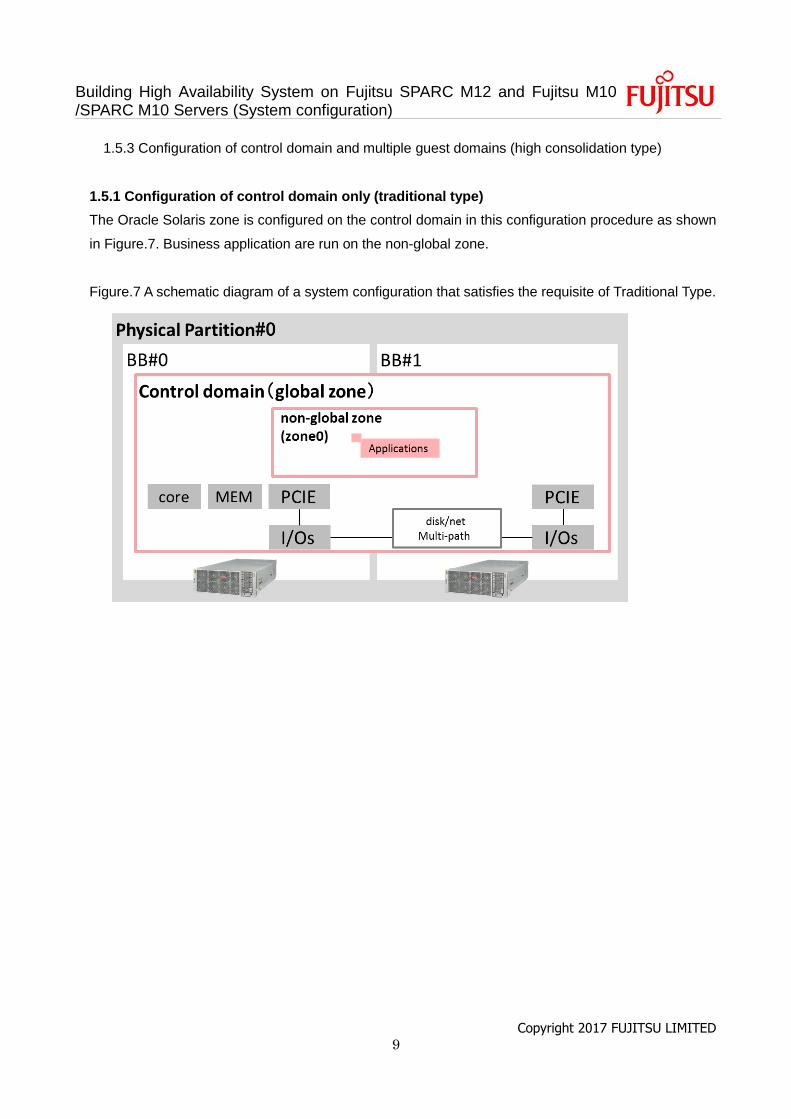
1.5.1 Configuration of control domain only (traditional type)
The Oracle Solaris zone is configured on the control domain in this configuration procedure as shown
in Figure.7. Business application are run on the non-global zone.
Figure.7 A schematic diagram of a system configuration that satisfies the requisite of Traditional Type.
Building High Availability System on Fujitsu SPARC M12 and Fujitsu M10 /SPARC M10 Servers (System configuration)
Copyright 2017 FUJITSU LIMITED 10
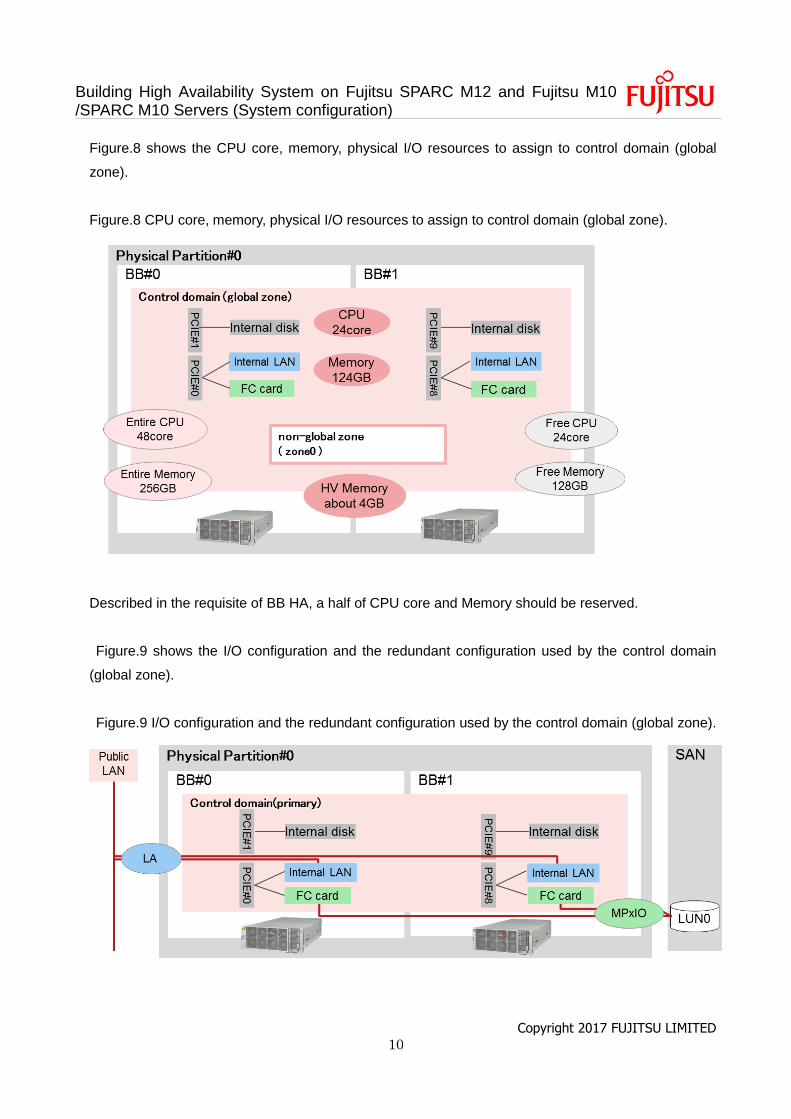
Figure.8 shows the CPU core, memory, physical I/O resources to assign to control domain (global
zone).
Figure.8 CPU core, memory, physical I/O resources to assign to control domain (global zone).
Described in the requisite of BB HA, a half of CPU core and Memory should be reserved.
Figure.9 shows the I/O configuration and the redundant configuration used by the control domain
(global zone).
Figure.9 I/O configuration and the redundant configuration used by the control domain (global zone).
Building High Availability System on Fujitsu SPARC M12 and Fujitsu M10 /SPARC M10 Servers (System configuration)
Copyright 2017 FUJITSU LIMITED 11
Described in the requisite of BB HA, control domain should be configured the redundant configuration
by assigning I/O devices in each BB’s disk volume and network interface.
In this example, each domain is configured the Link Aggregation (LA) with the network interfaces in
each BB. Also, control domain’s disk volume is the LUN on the Storage Area Network (SAN) and the
LUNs are multipathing by FibreChannel card in each BB.
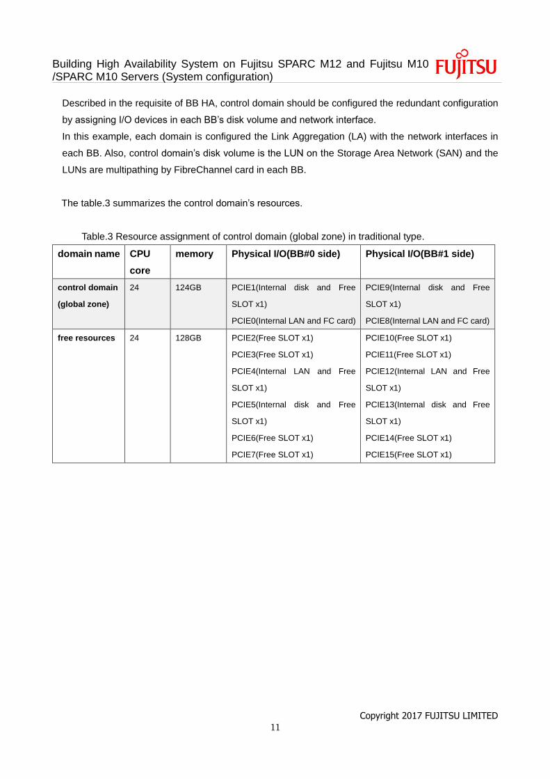
The table.3 summarizes the control domain’s resources.
Table.3 Resource assignment of control domain (global zone) in traditional type.
domain name CPU
core
memory Physical I/O(BB#0 side) Physical I/O(BB#1 side)
control domain
(global zone)
24 124GB PCIE1(Internal disk and Free
SLOT x1)
PCIE0(Internal LAN and FC card)
PCIE9(Internal disk and Free
SLOT x1)
PCIE8(Internal LAN and FC card)
free resources 24 128GB PCIE2(Free SLOT x1)
PCIE3(Free SLOT x1)
PCIE4(Internal LAN and Free
SLOT x1)
PCIE5(Internal disk and Free
SLOT x1)
PCIE6(Free SLOT x1)
PCIE7(Free SLOT x1)
PCIE10(Free SLOT x1)
PCIE11(Free SLOT x1)
PCIE12(Internal LAN and Free
SLOT x1)
PCIE13(Internal disk and Free
SLOT x1)
PCIE14(Free SLOT x1)
PCIE15(Free SLOT x1)
Building High Availability System on Fujitsu SPARC M12 and Fujitsu M10 /SPARC M10 Servers (System configuration)
Copyright 2017 FUJITSU LIMITED 12
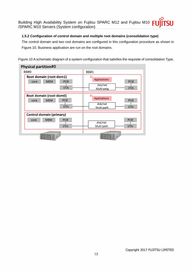
1.5.2 Configuration of control domain and multiple root domains (consolidation type)
The control domain and two root domains are configured in this configuration procedure as shown in
Figure.10. Business application are run on the root domains.
Figure.10 A schematic diagram of a system configuration that satisfies the requisite of consolidation Type.
Building High Availability System on Fujitsu SPARC M12 and Fujitsu M10 /SPARC M10 Servers (System configuration)
Copyright 2017 FUJITSU LIMITED 13
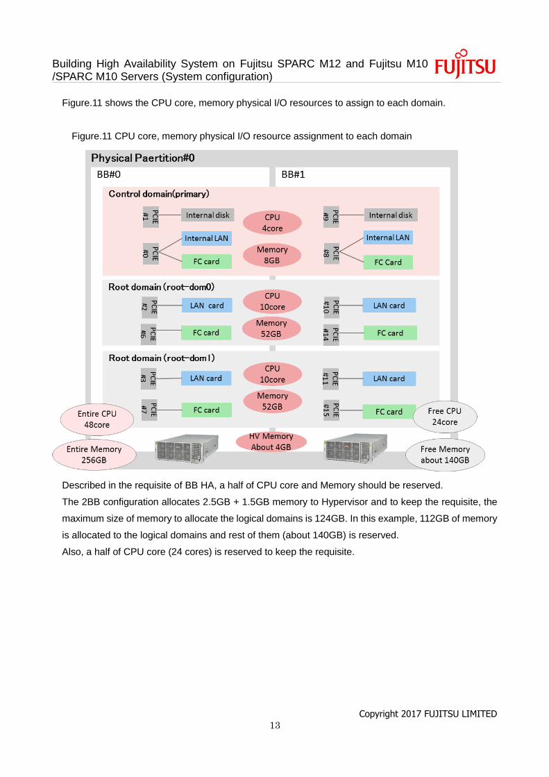
Figure.11 shows the CPU core, memory physical I/O resources to assign to each domain.
Figure.11 CPU core, memory physical I/O resource assignment to each domain
Described in the requisite of BB HA, a half of CPU core and Memory should be reserved.
The 2BB configuration allocates 2.5GB + 1.5GB memory to Hypervisor and to keep the requisite, the
maximum size of memory to allocate the logical domains is 124GB. In this example, 112GB of memory
is allocated to the logical domains and rest of them (about 140GB) is reserved.
Also, a half of CPU core (24 cores) is reserved to keep the requisite.
Building High Availability System on Fujitsu SPARC M12 and Fujitsu M10 /SPARC M10 Servers (System configuration)
Copyright 2017 FUJITSU LIMITED 14
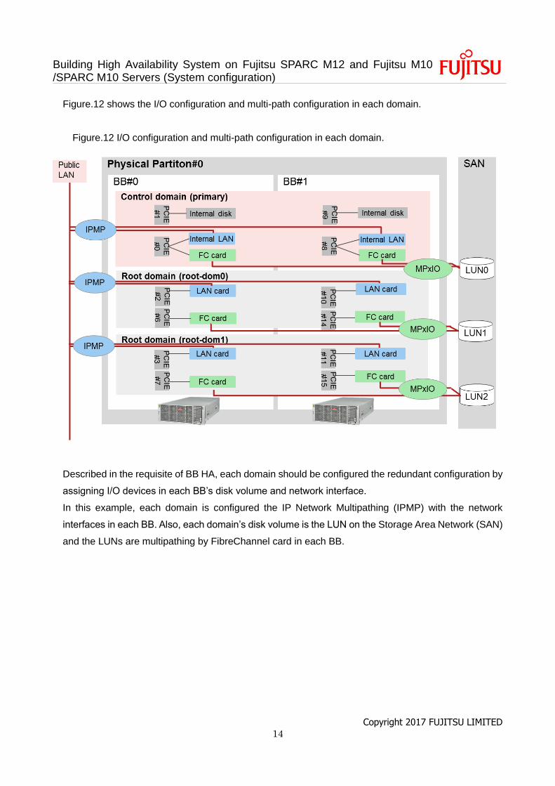
Figure.12 shows the I/O configuration and multi-path configuration in each domain.
Figure.12 I/O configuration and multi-path configuration in each domain.
Described in the requisite of BB HA, each domain should be configured the redundant configuration by
assigning I/O devices in each BB’s disk volume and network interface.
In this example, each domain is configured the IP Network Multipathing (IPMP) with the network
interfaces in each BB. Also, each domain’s disk volume is the LUN on the Storage Area Network (SAN)
and the LUNs are multipathing by FibreChannel card in each BB.
Building High Availability System on Fujitsu SPARC M12 and Fujitsu M10 /SPARC M10 Servers (System configuration)
Copyright 2017 FUJITSU LIMITED 15
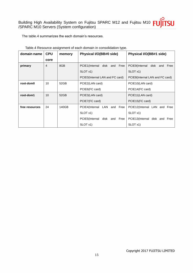
The table.4 summarizes the each domain’s resources.
Table.4 Resource assignment of each domain in consolidation type.
domain name CPU
core
memory Physical I/O(BB#0 side) Physical I/O(BB#1 side)
primary 4 8GB PCIE1(Internal disk and Free
SLOT x1)
PCIE0(Internal LAN and FC card)
PCIE9(Internal disk and Free
SLOT x1)
PCIE8(Internal LAN and FC card)
root-dom0 10 52GB PCIE2(LAN card)
PCIE6(FC card)
PCIE10(LAN card)
PCIE14(FC card)
root-dom1 10 52GB PCIE3(LAN card)
PCIE7(FC card)
PCIE11(LAN card)
PCIE15(FC card)
free resources 24 140GB PCIE4(Internal LAN and Free
SLOT x1)
PCIE5(Internal disk and Free
SLOT x1)
PCIE12(Internal LAN and Free
SLOT x1)
PCIE13(Internal disk and Free
SLOT x1)
Building High Availability System on Fujitsu SPARC M12 and Fujitsu M10 /SPARC M10 Servers (System configuration)
Copyright 2017 FUJITSU LIMITED 16
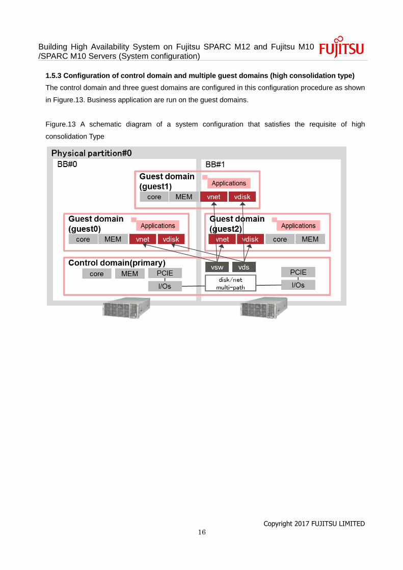
1.5.3 Configuration of control domain and multiple guest domains (high consolidation type)
The control domain and three guest domains are configured in this configuration procedure as shown
in Figure.13. Business application are run on the guest domains.
Figure.13 A schematic diagram of a system configuration that satisfies the requisite of high
consolidation Type
Building High Availability System on Fujitsu SPARC M12 and Fujitsu M10 /SPARC M10 Servers (System configuration)
Copyright 2017 FUJITSU LIMITED 17
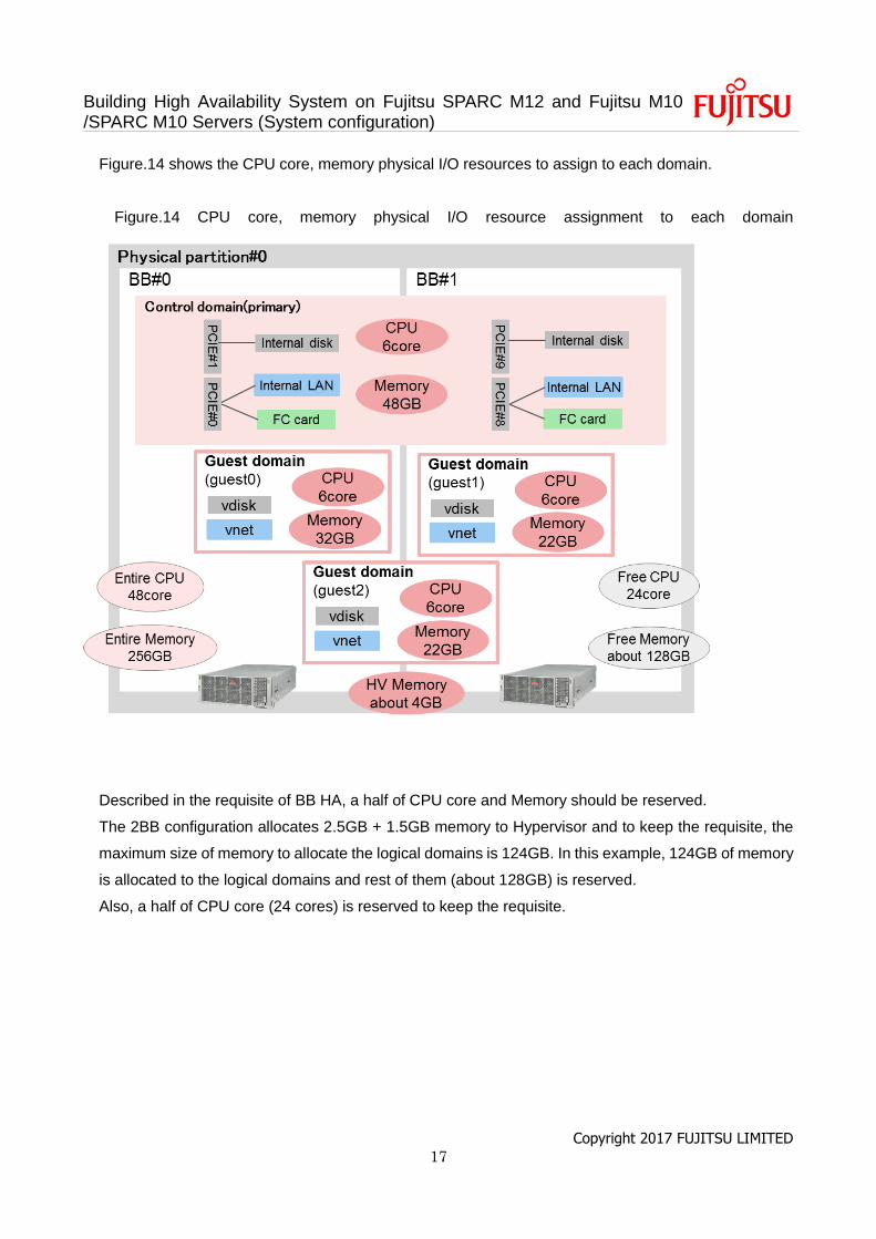
Figure.14 shows the CPU core, memory physical I/O resources to assign to each domain.
Figure.14 CPU core, memory physical I/O resource assignment to each domain
Described in the requisite of BB HA, a half of CPU core and Memory should be reserved.
The 2BB configuration allocates 2.5GB + 1.5GB memory to Hypervisor and to keep the requisite, the
maximum size of memory to allocate the logical domains is 124GB. In this example, 124GB of memory
is allocated to the logical domains and rest of them (about 128GB) is reserved.
Also, a half of CPU core (24 cores) is reserved to keep the requisite.
Building High Availability System on Fujitsu SPARC M12 and Fujitsu M10 /SPARC M10 Servers (System configuration)
Copyright 2017 FUJITSU LIMITED 18
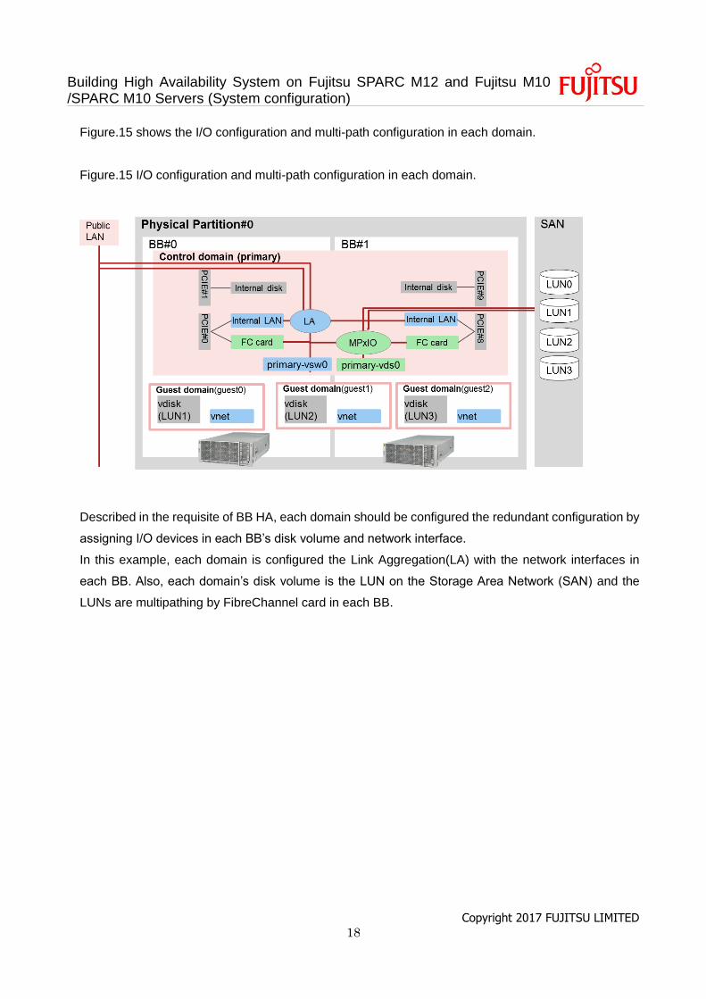
Figure.15 shows the I/O configuration and multi-path configuration in each domain.
Figure.15 I/O configuration and multi-path configuration in each domain.
Described in the requisite of BB HA, each domain should be configured the redundant configuration by
assigning I/O devices in each BB’s disk volume and network interface.
In this example, each domain is configured the Link Aggregation(LA) with the network interfaces in
each BB. Also, each domain’s disk volume is the LUN on the Storage Area Network (SAN) and the
LUNs are multipathing by FibreChannel card in each BB.
Building High Availability System on Fujitsu SPARC M12 and Fujitsu M10 /SPARC M10 Servers (System configuration)
Copyright 2017 FUJITSU LIMITED 19
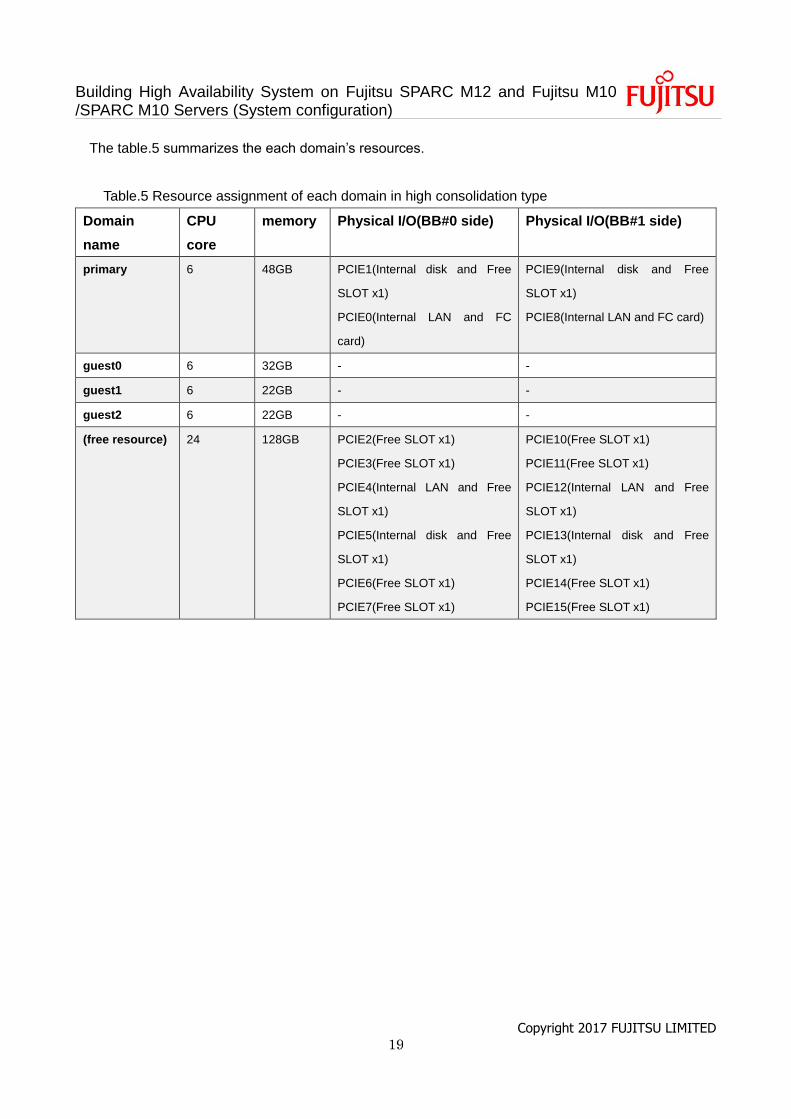
The table.5 summarizes the each domain’s resources.
Table.5 Resource assignment of each domain in high consolidation type
Domain
name
CPU
core
memory Physical I/O(BB#0 side) Physical I/O(BB#1 side)
primary 6 48GB PCIE1(Internal disk and Free
SLOT x1)
PCIE0(Internal LAN and FC
card)
PCIE9(Internal disk and Free
SLOT x1)
PCIE8(Internal LAN and FC card)
guest0 6 32GB - -
guest1 6 22GB - -
guest2 6 22GB - -
(free resource) 24 128GB PCIE2(Free SLOT x1)
PCIE3(Free SLOT x1)
PCIE4(Internal LAN and Free
SLOT x1)
PCIE5(Internal disk and Free
SLOT x1)
PCIE6(Free SLOT x1)
PCIE7(Free SLOT x1)
PCIE10(Free SLOT x1)
PCIE11(Free SLOT x1)
PCIE12(Internal LAN and Free
SLOT x1)
PCIE13(Internal disk and Free
SLOT x1)
PCIE14(Free SLOT x1)
PCIE15(Free SLOT x1)
Building High Availability System on Fujitsu SPARC M12 and Fujitsu M10 /SPARC M10 Servers (System configuration)
Copyright 2017 FUJITSU LIMITED 20
1.6 The flow of system configuration
This chapter explains the flow of the configuration procedure of three types of BB HA in the following
paragraphs.
1.6.1. The flow of configuration of traditional type
1.6.2. The flow of configuration of consolidation type
1.6.3. The flow of configuration of high consolidation type
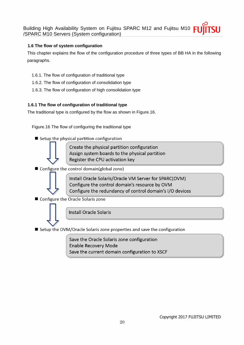
1.6.1 The flow of configuration of traditional type
The traditional type is configured by the flow as shown in Figure.16.
Figure.16 The flow of configuring the traditional type
Building High Availability System on Fujitsu SPARC M12 and Fujitsu M10 /SPARC M10 Servers (System configuration)
Copyright 2017 FUJITSU LIMITED 21
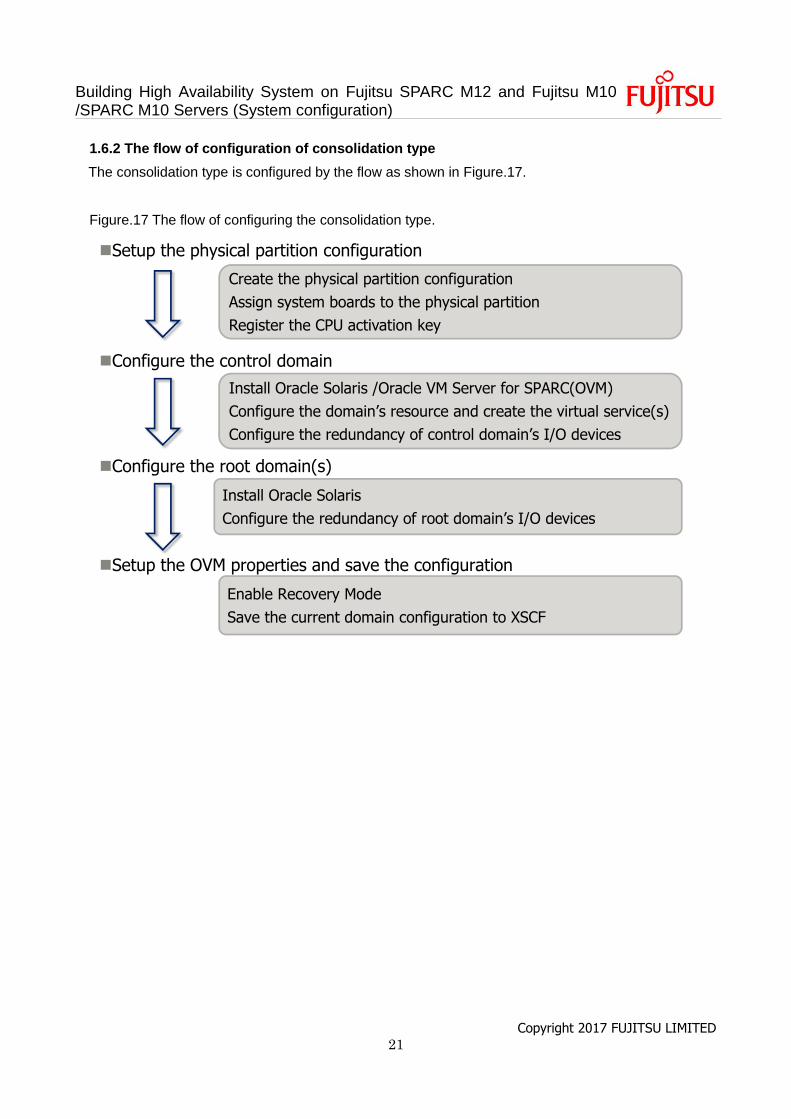
1.6.2 The flow of configuration of consolidation type
The consolidation type is configured by the flow as shown in Figure.17.
Figure.17 The flow of configuring the consolidation type.
Install Oracle Solaris
Configure the redundancy of root domain’s I/O devices
Install Oracle Solaris /Oracle VM Server for SPARC(OVM)
Configure the domain’s resource and create the virtual service(s)
Configure the redundancy of control domain’s I/O devices
Create the physical partition configuration
Assign system boards to the physical partition
Register the CPU activation key
Setup the physical partition configuration
Configure the control domain
Configure the root domain(s)
Enable Recovery Mode
Save the current domain configuration to XSCF
Setup the OVM properties and save the configuration
Building High Availability System on Fujitsu SPARC M12 and Fujitsu M10 /SPARC M10 Servers (System configuration)
Copyright 2017 FUJITSU LIMITED 22
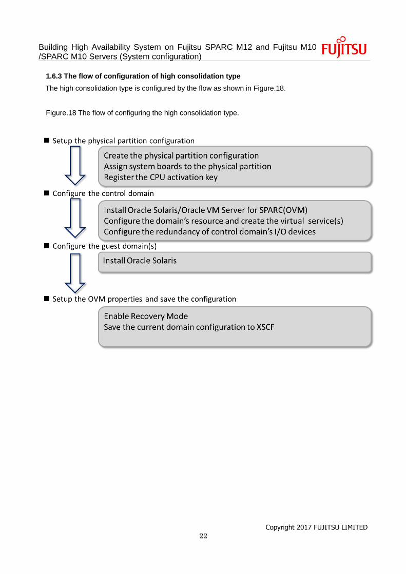
1.6.3 The flow of configuration of high consolidation type
The high consolidation type is configured by the flow as shown in Figure.18.
Figure.18 The flow of configuring the high consolidation type.
Building High Availability System on Fujitsu SPARC M12 and Fujitsu M10 /SPARC M10 Servers (System configuration)
Copyright 2017 FUJITSU LIMITED 23
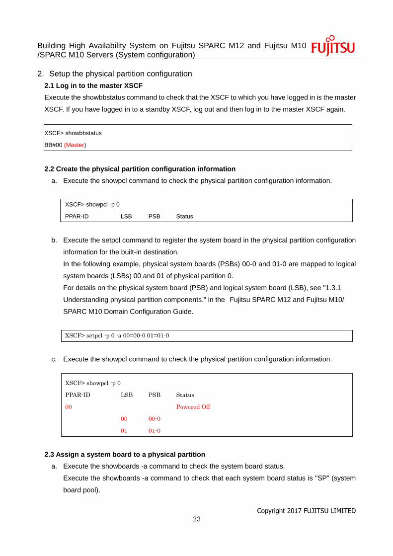
2. Setup the physical partition configuration
2.1 Log in to the master XSCF
Execute the showbbstatus command to check that the XSCF to which you have logged in is the master
XSCF. If you have logged in to a standby XSCF, log out and then log in to the master XSCF again.
XSCF> showbbstatus
BB#00 (Master)
2.2 Create the physical partition configuration information
a. Execute the showpcl command to check the physical partition configuration information.
XSCF> showpcl -p 0
PPAR-ID LSB PSB Status
b. Execute the setpcl command to register the system board in the physical partition configuration
information for the built-in destination.
In the following example, physical system boards (PSBs) 00-0 and 01-0 are mapped to logical
system boards (LSBs) 00 and 01 of physical partition 0.
For details on the physical system board (PSB) and logical system board (LSB), see "1.3.1
Understanding physical partition components." in the Fujitsu SPARC M12 and Fujitsu M10/
SPARC M10 Domain Configuration Guide.
XSCF> setpcl -p 0 -a 00=00-0 01=01-0
c. Execute the showpcl command to check the physical partition configuration information.
XSCF> showpcl -p 0
PPAR-ID LSB PSB Status
00 Powered Off
00 00-0
01 01-0
2.3 Assign a system board to a physical partition
a. Execute the showboards -a command to check the system board status.
Execute the showboards -a command to check that each system board status is "SP" (system
board pool).
Building High Availability System on Fujitsu SPARC M12 and Fujitsu M10 /SPARC M10 Servers (System configuration)
Copyright 2017 FUJITSU LIMITED 24
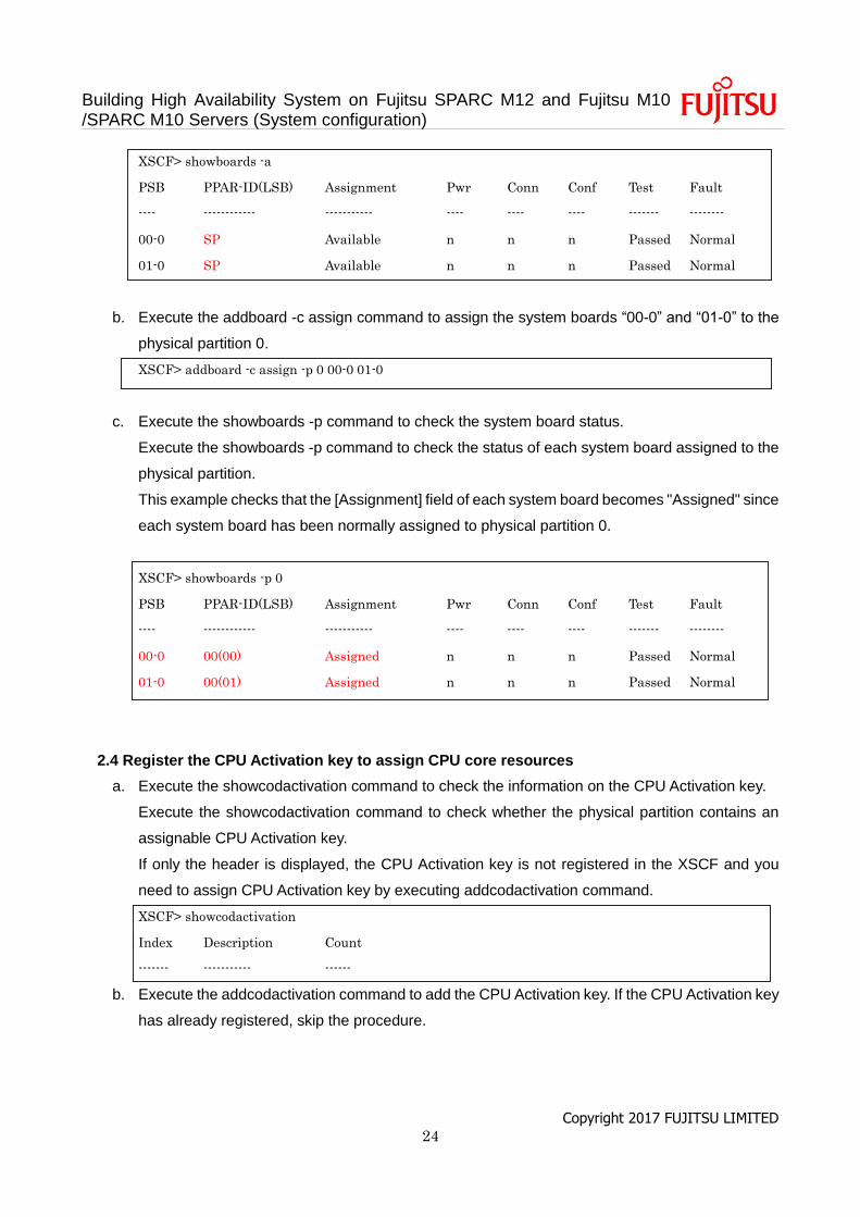
XSCF> showboards -a
PSB PPAR-ID(LSB) Assignment Pwr Conn Conf Test Fault
---- ------------ ----------- ---- ---- ---- ------- --------
00-0 SP Available n n n Passed Normal
01-0 SP Available n n n Passed Normal
b. Execute the addboard -c assign command to assign the system boards “00-0” and “01-0” to the
physical partition 0.
XSCF> addboard -c assign -p 0 00-0 01-0
c. Execute the showboards -p command to check the system board status.
Execute the showboards -p command to check the status of each system board assigned to the
physical partition.
This example checks that the [Assignment] field of each system board becomes "Assigned" since
each system board has been normally assigned to physical partition 0.
XSCF> showboards -p 0
PSB PPAR-ID(LSB) Assignment Pwr Conn Conf Test Fault
---- ------------ ----------- ---- ---- ---- ------- --------
00-0 00(00) Assigned n n n Passed Normal
01-0 00(01) Assigned n n n Passed Normal
2.4 Register the CPU Activation key to assign CPU core resources
a. Execute the showcodactivation command to check the information on the CPU Activation key.
Execute the showcodactivation command to check whether the physical partition contains an
assignable CPU Activation key.
If only the header is displayed, the CPU Activation key is not registered in the XSCF and you
need to assign CPU Activation key by executing addcodactivation command.
XSCF> showcodactivation
Index Description Count
------- ----------- ------
b. Execute the addcodactivation command to add the CPU Activation key. If the CPU Activation key
has already registered, skip the procedure.
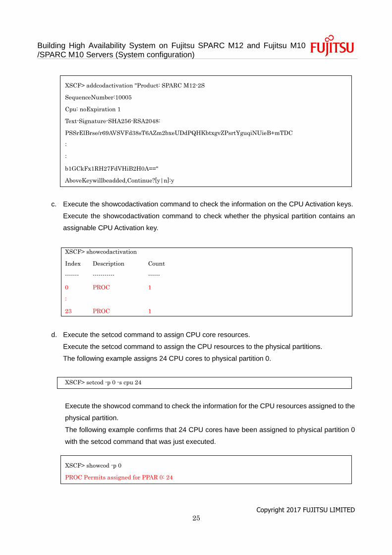
Building High Availability System on Fujitsu SPARC M12 and Fujitsu M10 /SPARC M10 Servers (System configuration)
Copyright 2017 FUJITSU LIMITED 25
XSCF> addcodactivation "Product: SPARC M12-2S
SequenceNumber:10005
Cpu: noExpiration 1
Text-Signature-SHA256-RSA2048:
PSSrElBrse/r69AVSVFd38sT6AZm2bxeUDdPQHKbtxgvZPsrtYguqiNUieB+mTDC
:
:
b1GCkFx1RH27FdVHiB2H0A=="
AboveKeywillbeadded,Continue?[y|n]:y
c. Execute the showcodactivation command to check the information on the CPU Activation keys.
Execute the showcodactivation command to check whether the physical partition contains an
assignable CPU Activation key.
XSCF> showcodactivation
Index Description Count
------- ----------- ------
0 PROC 1
:
23 PROC 1
d. Execute the setcod command to assign CPU core resources.
Execute the setcod command to assign the CPU resources to the physical partitions.
The following example assigns 24 CPU cores to physical partition 0.
XSCF> setcod -p 0 -s cpu 24
Execute the showcod command to check the information for the CPU resources assigned to the
physical partition.
The following example confirms that 24 CPU cores have been assigned to physical partition 0
with the setcod command that was just executed.
XSCF> showcod -p 0
PROC Permits assigned for PPAR 0: 24
Building High Availability System on Fujitsu SPARC M12 and Fujitsu M10 /SPARC M10 Servers (System configuration)
Copyright 2017 FUJITSU LIMITED 26
2.5 Reset the time correction in XSCF
Execute the resetdateoffset command to reset the difference between the time managed by the XSCF
and the time managed by the physical partitions.
XSCF> resetdateoffset -p 0
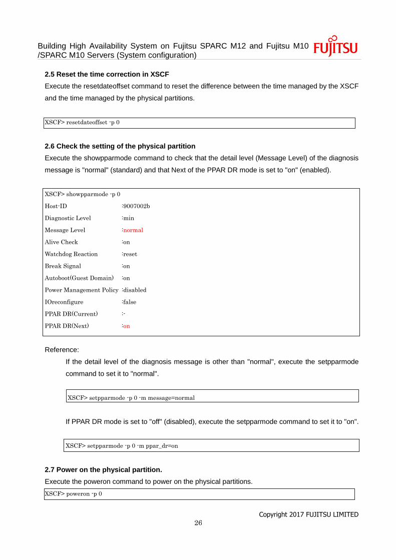
2.6 Check the setting of the physical partition
Execute the showpparmode command to check that the detail level (Message Level) of the diagnosis
message is "normal" (standard) and that Next of the PPAR DR mode is set to "on" (enabled).
XSCF> showpparmode -p 0
Host-ID :9007002b
Diagnostic Level :min
Message Level :normal
Alive Check :on
Watchdog Reaction :reset
Break Signal :on
Autoboot(Guest Domain) :on
Power Management Policy :disabled
IOreconfigure :false
PPAR DR(Current) :-
PPAR DR(Next) :on
Reference:
If the detail level of the diagnosis message is other than "normal", execute the setpparmode
command to set it to "normal".
XSCF> setpparmode -p 0 -m message=normal
If PPAR DR mode is set to "off" (disabled), execute the setpparmode command to set it to "on".
XSCF> setpparmode -p 0 -m ppar_dr=on
2.7 Power on the physical partition.
Execute the poweron command to power on the physical partitions.
XSCF> poweron -p 0

Building High Availability System on Fujitsu SPARC M12 and Fujitsu M10 /SPARC M10 Servers (System configuration)
Copyright 2017 FUJITSU LIMITED 27
2.8 Connect the console to the physical partition.
Execute the console command to connect the console to the physical partition.
XSCF> console -p 0
Building High Availability System on Fujitsu SPARC M12 and Fujitsu M10 /SPARC M10 Servers (System configuration)
Copyright 2017 FUJITSU LIMITED 28
3. Configure of the traditional type
This chapter explains the configuration procedure of the traditional type.
3.1 Install Oracle Solaris and Oracle VM Server for SPARC
Install Oracle Solaris and Oracle VM Server for SPARC on the control domain (global zone).
For details on the versions and conditions of Oracle Solaris and Oracle VM Server for SPARC required
for BB HA, see “Building a High Availability System on Fujitsu SPARC M12 and Fujitsu M10/SPARC
M10 Servers (Overview)”.
For details on the installation, see the following documents, presented on the Oracle Corporation
homepage (http://docs.oracle.com/).
- Oracle Solaris 11
Installing Oracle Solaris 11.2 Systems
- Oracle VM Server for SPARC
"Installing and Enabling Software" in the Oracle VM Server for SPARC Installation Guide
3.2 Configure the control domain (global zone)
This item describes how to configure the logical domains defined in "Table.3 Resource assignment of
control domain (global zone) in traditional type."
a. Release the control domain (global zone) resources.
In the factory-default configuration, all the CPU cores, memory, and the PCIe root complexes are
assigned to the control domain (primary). To allow these resources to be assigned to other logical
domains, release some of the resources from the control domain.
Execute the ldm start-reconf command to switch to delayed reconfiguration mode.
primary# ldm start-reconf primary
Initiating a delayed reconfiguration operation on the primary domain.
All configuration changes for other domains are disabled until the primary
domain reboots, at which time the new configuration for the primary domain
will also take effect.
Reduce the number of CPU cores and the size of memory assigned to the control domain by
specifying a size smaller than the original size with the ldm set-core and ldm set-memory
commands.
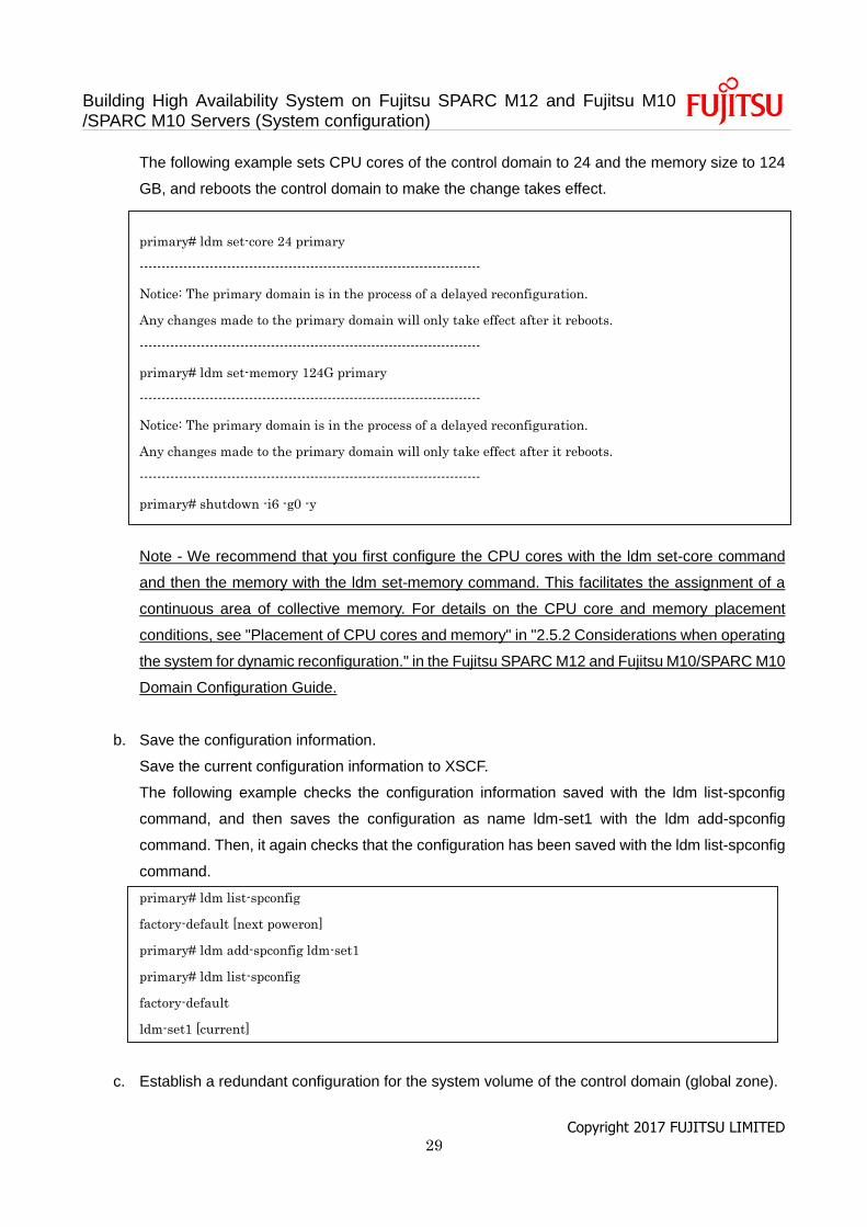
Building High Availability System on Fujitsu SPARC M12 and Fujitsu M10 /SPARC M10 Servers (System configuration)
Copyright 2017 FUJITSU LIMITED 29
The following example sets CPU cores of the control domain to 24 and the memory size to 124
GB, and reboots the control domain to make the change takes effect.
primary# ldm set-core 24 primary
------------------------------------------------------------------------------
Notice: The primary domain is in the process of a delayed reconfiguration.
Any changes made to the primary domain will only take effect after it reboots.
------------------------------------------------------------------------------
primary# ldm set-memory 124G primary
------------------------------------------------------------------------------
Notice: The primary domain is in the process of a delayed reconfiguration.
Any changes made to the primary domain will only take effect after it reboots.
------------------------------------------------------------------------------
primary# shutdown -i6 -g0 -y
Note - We recommend that you first configure the CPU cores with the ldm set-core command
and then the memory with the ldm set-memory command. This facilitates the assignment of a
continuous area of collective memory. For details on the CPU core and memory placement
conditions, see "Placement of CPU cores and memory" in "2.5.2 Considerations when operating
the system for dynamic reconfiguration." in the Fujitsu SPARC M12 and Fujitsu M10/SPARC M10
Domain Configuration Guide.
b. Save the configuration information.
Save the current configuration information to XSCF.
The following example checks the configuration information saved with the ldm list-spconfig
command, and then saves the configuration as name ldm-set1 with the ldm add-spconfig
command. Then, it again checks that the configuration has been saved with the ldm list-spconfig
command.
primary# ldm list-spconfig
factory-default [next poweron]
primary# ldm add-spconfig ldm-set1
primary# ldm list-spconfig
factory-default
ldm-set1 [current]
c. Establish a redundant configuration for the system volume of the control domain (global zone).
Building High Availability System on Fujitsu SPARC M12 and Fujitsu M10 /SPARC M10 Servers (System configuration)
Copyright 2017 FUJITSU LIMITED 30
This item describes how to configure the redundant system volume on the SAN using
FibreChannel port multipath. To use other redundant configuration software, see the manual for
that software.
Add the following lines to /etc/system file on the control domain (global zone) to reduce the start-
up time and suspending time during the PPAR DR. Also, to reduce such the time, connect the
optical cable to each FibreChannel port and link up of the ports.
forceload: drv/qlc
forceload: drv/emlxs
forceload: drv/ssd
forceload: drv/fp
set lgrp_topo_levels=1
Execute the stmsboot command to check the current multipath configuration.
The following example indicates that the multipath configuration is disabled.
primary# stmsboot -D fp -L
stmsboot: MPXIO disabled
Execute the stmsboot command to enable the multipath configuration. It needs reboot of the
control domain.
primary# stmsboot -D fp -e
After the control domain reboots, execute the stmsboot command to check the multipath
configuration.
The following example indicates that the 2 disk paths are recognized as one multipath disk.
primary# stmsboot -D fp -L
non-STMS device name STMS device name
------------------------------------------------------------------
/dev/rdsk/c10t500000E0D0000087d0 /dev/rdsk/c0t600000E00D0000000000000000000000d0
/dev/rdsk/c9t500000E0D0000086d0 /dev/rdsk/c0t600000E00D0000000000000000000000d0
Execute ldm command to set the 2 disk paths to the boot-device of the control domain. To
confirm the relation about the disk paths and the multipath disk, see the manual for the redundant
configuration software.
Building High Availability System on Fujitsu SPARC M12 and Fujitsu M10 /SPARC M10 Servers (System configuration)
Copyright 2017 FUJITSU LIMITED 31
primary# ldm set-variable boot-device=¥
"/pci@8100/pci@4/pci@0/pci@0/SUNW,qlc@0/fp@0,0/disk@w500000e0d0000086,0¥
/pci@8900/pci@4/pci@0/pci@0/SUNW,qlc@0,1/fp@0,0/disk@w500000e0d0000087,0 disk net" primary
d. Check the configuration of the control domain (global zone).
Execute ldm command to check the configuration of the control domain (global zone). Following
example confirms the CPU cores, Memory and physical I/O devices are same as “Table.3
Resource assignment of control domain (global zone) in traditional type”, and the configurations
in the section worked correctly.
Building High Availability System on Fujitsu SPARC M12 and Fujitsu M10 /SPARC M10 Servers (System configuration)
Copyright 2017 FUJITSU LIMITED 32
primary# ldm list-domain -l
NAME STATE FLAGS CONS VCPU MEMORY UTIL NORM UPTIME
primary active -n-c-- UART 192 124G 0.0% 0.0% 27m
:
VARIABLES
auto-boot?=false
boot-device=/pci@8100/pci@4/pci@0/pci@0/SUNW,qlc@0/fp@0,0/disk@w500000e0d0000086,0
/pci@8900/pci@4/pci@0/pci@0/SUNW,qlc@0,1/fp@0,0/disk@w500000e0d0000087,0
disk net
pm_boot_policy=disabled=1;ttfc=0;ttmr=0;
IO
DEVICE PSEUDONYM OPTIONS
DEVICE PSEUDONYM OPTIONS
pci@8000 PCIE0
pci@8100 PCIE1
pci@8200 PCIE2
pci@8300 PCIE3
pci@8400 PCIE4
pci@8500 PCIE5
pci@8600 PCIE6
pci@8700 PCIE7
pci@8800 PCIE8
pci@8900 PCIE9
pci@8a00 PCIE10
pci@8b00 PCIE11
pci@8c00 PCIE12
pci@8d00 PCIE13
pci@8e00 PCIE14
pci@8f00 PCIE15
Building High Availability System on Fujitsu SPARC M12 and Fujitsu M10 /SPARC M10 Servers (System configuration)
Copyright 2017 FUJITSU LIMITED 33
e. Establish a redundant configuration for the network interface of the control domain (global zone).
The following describes an example of the procedure for establishing a redundant configuration
for two physical network interfaces assigned to the control domain primary, using LA. For details
on the procedures for other redundant configurations, see the documentation for the software for
the respective redundant configurations.
Execute the dladm command to check that the virtual network devices are visible.
In the example below, it is possible to refer to virtual network devices as network interfaces net0
and net4. Moreover, it is understood that net0 is under the control of system board 00-0(BB#0),
and net4 is under the control of system board 01-0(BB#1).
primary# dladm show-link
LINK CLASS MTU STATE OVER
net0 phys 1500 up --
net4 phys 1500 up --
primary# dladm show-phys -L
LINK DEVICE LOC
net0 ixgbe0 /BB0/CMUL
:
net4 ixgbe4 /BB1/CMUL
Execute the ipadm show-if command to check that net0 and net4 are not displayed.
primary# ipadm show-if
IFNAME CLASS STATE ACTIVE OVER
lo0 loopback ok yes --
If the network device to be configured in the LA is displayed as an IP interface, delete the IP
interface.
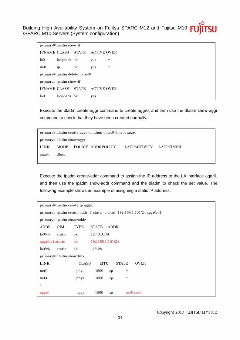
Building High Availability System on Fujitsu SPARC M12 and Fujitsu M10 /SPARC M10 Servers (System configuration)
Copyright 2017 FUJITSU LIMITED 34
primary# ipadm show-if
IFNAME CLASS STATE ACTIVE OVER
lo0 loopback ok yes --
net0 ip ok yes --
primary# ipadm delete-ip net0
primary# ipadm show-if
IFNAME CLASS STATE ACTIVE OVER
lo0 loopback ok yes --
Execute the dladm create-aggr command to create aggr0, and then use the dladm show-aggr
command to check that they have been created normally.
primary# dladm create-aggr -m dlmp -l net0 -l net4 aggr0
primary# dladm show-aggr
LINK MODE POLICY ADDRPOLICY LACPACTIVITY LACPTIMER
aggr0 dlmp -- -- -- --
Execute the ipadm create-addr command to assign the IP address to the LA interface aggr0,
and then use the ipadm show-addr command and the dladm to check the set value. The
following example shows an example of assigning a static IP address.
primary# ipadm create-ip aggr0
primary# ipadm create-addr -T static -a local=192.168.1.101/24 aggr0/v4
primary# ipadm show-addr
ADDR OBJ TYPE STATE ADDR
lo0/v4 static ok 127.0.0.1/8
aggr0/v4 static ok 192.168.1.101/24
lo0/v6 static ok ::1/128
primary# dladm show-link
LINK CLASS MTU STATE OVER
net0 phys 1500 up --
net4 phys 1500 up --
:
aggr0 aggr 1500 up net0 net4
Building High Availability System on Fujitsu SPARC M12 and Fujitsu M10 /SPARC M10 Servers (System configuration)
Copyright 2017 FUJITSU LIMITED 35
3.3 Configure the Oracle Solaris zone
This item describes the procedure for configuration of the Oracle Solaris zones. When the Oracle
Solaris zone is not used, the execution of the procedure is not necessary. Please proceed to “6. Save
the configuration information”.
For details of the procedure for configuration, see the following documents, presented on the Oracle
Corporation homepage (http://docs.oracle.com/).
- Oracle Solaris 11
Oracle Solaris 11.2 Information Library
- Creating and using Oracle Solaris virtual environments
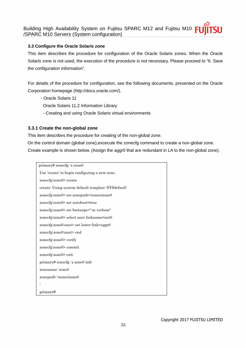
3.3.1 Create the non-global zone
This item describes the procedure for creating of the non-global zone.
On the control domain (global zone),excecute the zonecfg command to create a non-global zone.
Create example is shown below. (Assign the aggr0 that are redundant in LA to the non-global zone).
primary# zonecfg -z zone0
Use 'create' to begin configuring a new zone.
zonecfg:zone0> create
create: Using system default template 'SYSdefault'
zonecfg:zone0> set zonepath=/zones/zone0
zonecfg:zone0> set autoboot=true
zonecfg:zone0> set bootargs="-m verbose"
zonecfg:zone0> select anet linkname=net0
zonecfg:zone0:anet> set lower-link=aggr0
zonecfg:zone0:anet> end
zonecfg:zone0> verify
zonecfg:zone0> commit
zonecfg:zone0> exit
primary# zonecfg -z zone0 info
zonename: zone0
zonepath: /zones/zone0
:
primary#
Building High Availability System on Fujitsu SPARC M12 and Fujitsu M10 /SPARC M10 Servers (System configuration)
Copyright 2017 FUJITSU LIMITED 36
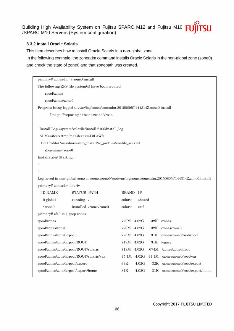
3.3.2 Install Oracle Solaris
This item describes how to install Oracle Solaris in a non-global zone.
In the following example, the zoneadm command installs Oracle Solaris in the non-global zone (zone0)
and check the state of zone0 and that zonepath was created.
primary# zoneadm -z zone0 install
The following ZFS file system(s) have been created:
rpool/zones
rpool/zones/zone0
Progress being logged to /var/log/zones/zoneadm.20150805T144314Z.zone0.install
Image: Preparing at /zones/zone0/root.
Install Log: /system/volatile/install.2106/install_log
AI Manifest: /tmp/manifest.xml.0LaWfe
SC Profile: /usr/share/auto_install/sc_profiles/enable_sci.xml
Zonename: zone0
Installation: Starting ...
:
:
Log saved in non-global zone as /zones/zone0/root/var/log/zones/zoneadm.20150805T144314Z.zone0.install
primary# zoneadm list -iv
ID NAME STATUS PATH BRAND IP
0 global running / solaris shared
- zone0 installed /zones/zone0 solaris excl
primary# zfs list | grep zones
rpool/zones 720M 4.02G 32K /zones
rpool/zones/zone0 720M 4.02G 32K /zones/zone0
rpool/zones/zone0/rpool 720M 4.02G 31K /zones/zone0/root/rpool
rpool/zones/zone0/rpool/ROOT 719M 4.02G 31K legacy
rpool/zones/zone0/rpool/ROOT/solaris 719M 4.02G 674M /zones/zone0/root
rpool/zones/zone0/rpool/ROOT/solaris/var 45.1M 4.02G 44.1M /zones/zone0/root/var
rpool/zones/zone0/rpool/export 63K 4.02G 32K /zones/zone0/root/export
rpool/zones/zone0/rpool/export/home 31K 4.02G 31K /zones/zone0/root/export/home

Building High Availability System on Fujitsu SPARC M12 and Fujitsu M10 /SPARC M10 Servers (System configuration)
Copyright 2017 FUJITSU LIMITED 37
3.3.3 Establish a system configuration of non-global zone
This item describes how to set up and start the system configuration in the non-global zone.
Execute the following command to start the non-global zone and access the console.
primary# zoneadm -z zone0 boot; zlogin -C zone0
According to the menu screen, when setting the system configuration of the non-global zone is
completed, the non-global zone will be started and the prompt of console login will be displayed.
[ system/console-login:default starting (Console login) ]
zone0 console login:
Log in to the non-global zone and check the IP address.
root@zone0:~# ipadm show-addr
ADDROBJ TYPE STATE ADDR
lo0/v4 static ok 127.0.0.1/8
net0/v4 static ok 192.168.1.102/24
lo0/v6 static ok :: 1/128
net0/v6 addrconf ok fe80::8:20ff:fe85:423d/10
root@zone0:~#
Enter "~.", and then exit the console.
root@zone0:~# exit
logout
zone0 console login: ~.
[Connection to zone 'zone0' console closed]
primary#
Building High Availability System on Fujitsu SPARC M12 and Fujitsu M10 /SPARC M10 Servers (System configuration)
Copyright 2017 FUJITSU LIMITED 38
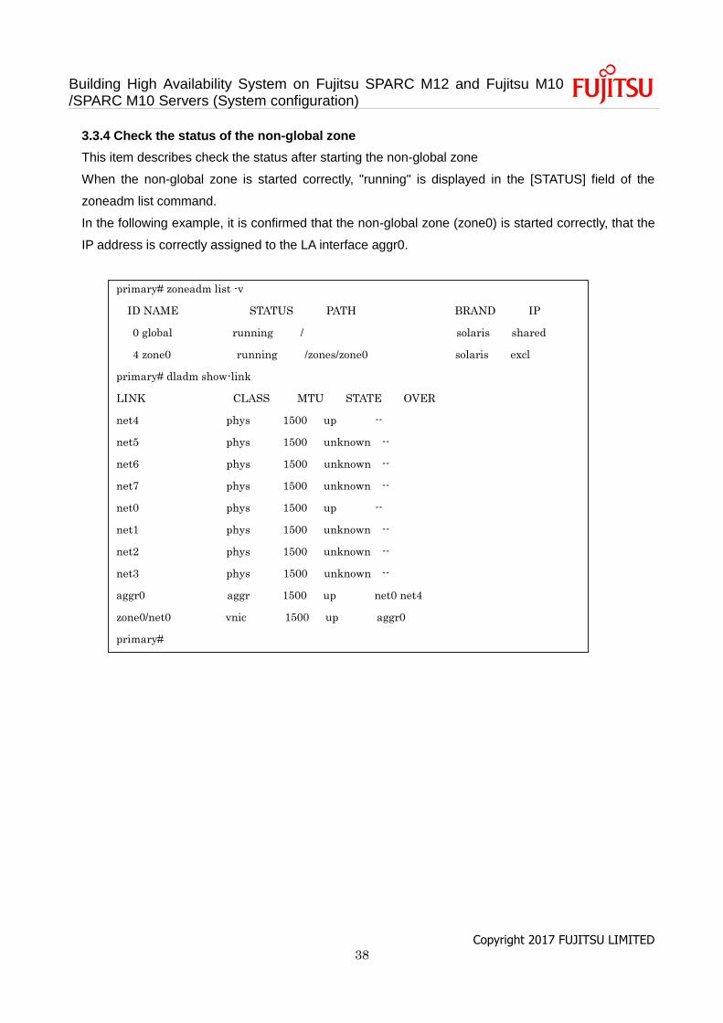
3.3.4 Check the status of the non-global zone
This item describes check the status after starting the non-global zone
When the non-global zone is started correctly, "running" is displayed in the [STATUS] field of the
zoneadm list command.
In the following example, it is confirmed that the non-global zone (zone0) is started correctly, that the
IP address is correctly assigned to the LA interface aggr0.
primary# zoneadm list -v
ID NAME STATUS PATH BRAND IP
0 global running / solaris shared
4 zone0 running /zones/zone0 solaris excl
primary# dladm show-link
LINK CLASS MTU STATE OVER
net4 phys 1500 up --
net5 phys 1500 unknown --
net6 phys 1500 unknown --
net7 phys 1500 unknown --
net0 phys 1500 up --
net1 phys 1500 unknown --
net2 phys 1500 unknown --
net3 phys 1500 unknown --
aggr0 aggr 1500 up net0 net4
zone0/net0 vnic 1500 up aggr0
primary#
Building High Availability System on Fujitsu SPARC M12 and Fujitsu M10 /SPARC M10 Servers (System configuration)
Copyright 2017 FUJITSU LIMITED 39
4. Configure of the consolidation type
This chapter explains the configuration procedure of the consolidation type.
4.1 Install Oracle Solaris and Oracle VM Server for SPARC.
Install Oracle Solaris and Oracle VM Server for SPARC on the control domain.
For details on the versions and conditions of Oracle Solaris and Oracle VM Server for SPARC required
for BB HA, see “Building a High Availability System on Fujitsu SPARC M12 and Fujitsu M10/SPARC
M10 Servers (overview)”.
For details on the installation, see the following documents, presented on the Oracle Corporation
website (http://docs.oracle.com/).
- Oracle Solaris 11
Installing Oracle Solaris 11.2 Systems
- Oracle VM Server for SPARC
"Installing and Enabling Software" in the Oracle VM Server for SPARC Administration Guide
4.2 Configure the logical domain(s)
This item describes how to configure the logical domains defined in "Table.4 Resource assignment in
each domain."
a. Release the control domain resources.
In the factory-default configuration, all the CPU cores, memory, and the PCIe root complexes are
assigned to the control domain (primary). To allow these resources to be assigned to other logical
domains, release some of the resources from the control domain.
Execute the ldm start-reconf command to switch to delayed reconfiguration mode.
primary# ldm start-reconf primary
Initiating a delayed reconfiguration operation on the primary domain.
All configuration changes for other domains are disabled until the primary
domain reboots, at which time the new configuration for the primary domain
will also take effect.
Remove the root complex with the ldm remove-io command.

Building High Availability System on Fujitsu SPARC M12 and Fujitsu M10 /SPARC M10 Servers (System configuration)
Copyright 2017 FUJITSU LIMITED 40
The following example partially describes the command for removing PCIE2, PCIE3, PCIE4,
PCIE5, PCIE6, PCIE7, PCIE10, PCIE11, PCIE12, PCIE13, PCIE14, and PCIE15 according to
the configuration example.
primary# ldm remove-io PCIE2 primary
------------------------------------------------------------------------------
Notice: The primary domain is in the process of a delayed reconfiguration.
Any changes made to the primary domain will only take effect after it reboots.
------------------------------------------------------------------------------
....
primary# ldm remove-io PCIE15 primary
------------------------------------------------------------------------------
Notice: The primary domain is in the process of a delayed reconfiguration.
Any changes made to the primary domain will only take effect after it reboots.
------------------------------------------------------------------------------
Reduce the number of CPU cores and the size of memory assigned to the control domain by
specifying a size smaller than the original size with the ldm set-core and ldm set-memory
commands.
The following example sets CPU cores of the control domain to 4 and the memory size to 8 GB,
and reboots the control domain to make the change takes effect.
primary# ldm set-core 4 primary
------------------------------------------------------------------------------
Notice: The primary domain is in the process of a delayed reconfiguration.
Any changes made to the primary domain will only take effect after it reboots.
------------------------------------------------------------------------------
primary# ldm set-memory 8G primary
------------------------------------------------------------------------------
Notice: The primary domain is in the process of a delayed reconfiguration.
Any changes made to the primary domain will only take effect after it reboots.
------------------------------------------------------------------------------
primary# shutdown -i6 -g0 -y
Building High Availability System on Fujitsu SPARC M12 and Fujitsu M10 /SPARC M10 Servers (System configuration)
Copyright 2017 FUJITSU LIMITED 41
Note - We recommend that you first configure the CPU cores with the ldm set-core command
and then the memory with the ldm set-memory command. This facilitates the assignment of a
continuous area of collective memory. For details on the CPU core and memory placement
conditions, see "Placement of CPU cores and memory" in "2.5.2 Considerations when
operating the system for dynamic reconfiguration." in the Fujitsu SPARC M12 and Fujitsu
M10/SPARC M10 Domain Configuration Guide.
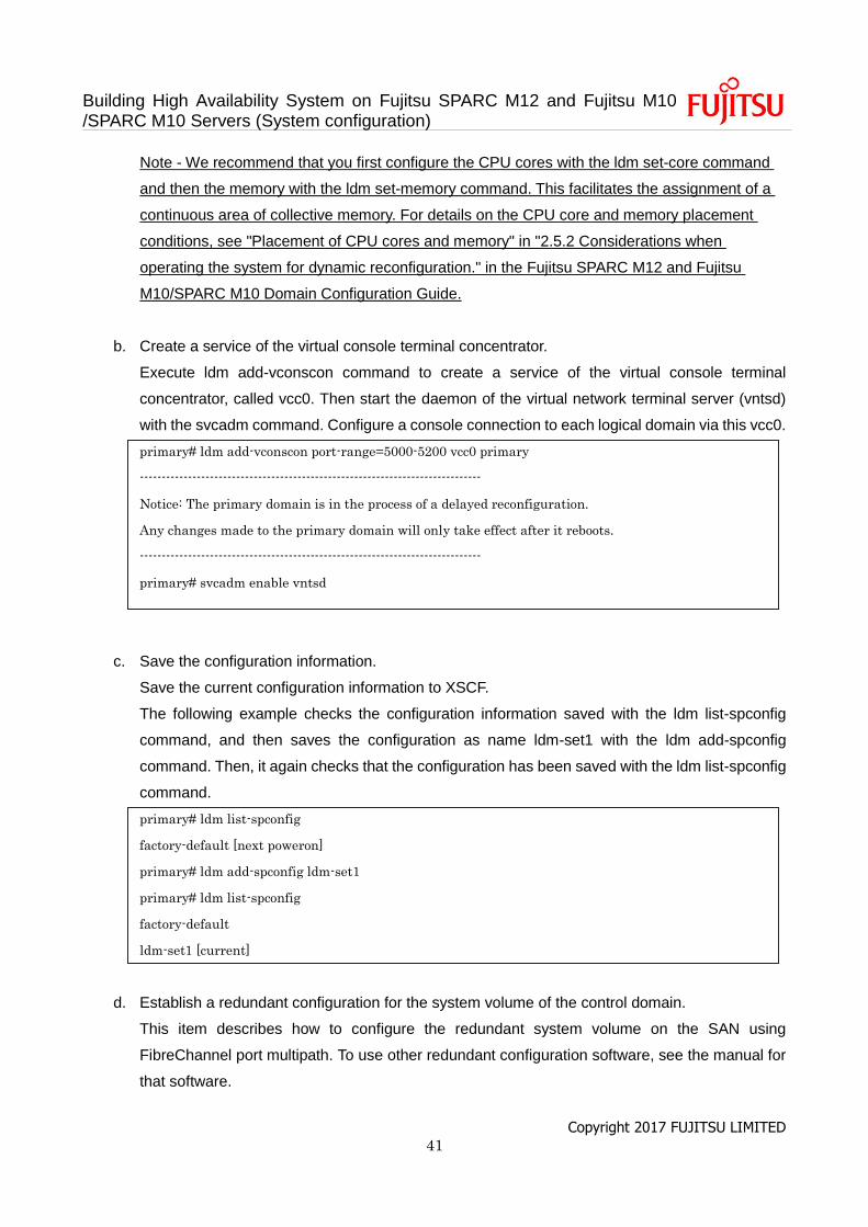
b. Create a service of the virtual console terminal concentrator.
Execute ldm add-vconscon command to create a service of the virtual console terminal
concentrator, called vcc0. Then start the daemon of the virtual network terminal server (vntsd)
with the svcadm command. Configure a console connection to each logical domain via this vcc0.
primary# ldm add-vconscon port-range=5000-5200 vcc0 primary
------------------------------------------------------------------------------
Notice: The primary domain is in the process of a delayed reconfiguration.
Any changes made to the primary domain will only take effect after it reboots.
------------------------------------------------------------------------------
primary# svcadm enable vntsd
c. Save the configuration information.
Save the current configuration information to XSCF.
The following example checks the configuration information saved with the ldm list-spconfig
command, and then saves the configuration as name ldm-set1 with the ldm add-spconfig
command. Then, it again checks that the configuration has been saved with the ldm list-spconfig
command.
primary# ldm list-spconfig
factory-default [next poweron]
primary# ldm add-spconfig ldm-set1
primary# ldm list-spconfig
factory-default
ldm-set1 [current]
d. Establish a redundant configuration for the system volume of the control domain.
This item describes how to configure the redundant system volume on the SAN using
FibreChannel port multipath. To use other redundant configuration software, see the manual for
that software.
Building High Availability System on Fujitsu SPARC M12 and Fujitsu M10 /SPARC M10 Servers (System configuration)
Copyright 2017 FUJITSU LIMITED 42
Add the following lines to /etc/system file on the control domain to reduce the start-up time and
suspending time during the PPAR DR. Also, to reduce such the time, connect the optical cable
to each FibreChannel port and link up of the ports.
forceload: drv/qlc
forceload: drv/emlxs
forceload: drv/ssd
forceload: drv/fp
set lgrp_topo_levels=1
Execute the stmsboot command to check the current multipath configuration.
The following example indicates that the multipath configuration is disabled.
primary# stmsboot -D fp -L
stmsboot: MPXIO disabled
Execute the stmsboot command to enable the multipath configuration. It needs reboot of the
control domain.
primary# stmsboot -D fp -e
After the control domain reboots, execute the stmsboot command to check the multipath
configuration.
The following example indicates that the 2 disk paths are recognized as one multipath disk.
primary# stmsboot -D fp -L
non-STMS device name STMS device name
------------------------------------------------------------------
/dev/rdsk/c10t500000E0D0000087d0 /dev/rdsk/c0t600000E00D0000000000000000000000d0
/dev/rdsk/c9t500000E0D0000086d0 /dev/rdsk/c0t600000E00D0000000000000000000000d0
Execute ldm command to set the 2 disk paths to the boot-device of the control domain. To
confirm the relation about the disk paths and the multipath disk, see the manual for the redundant
configuration software.
Building High Availability System on Fujitsu SPARC M12 and Fujitsu M10 /SPARC M10 Servers (System configuration)
Copyright 2017 FUJITSU LIMITED 43
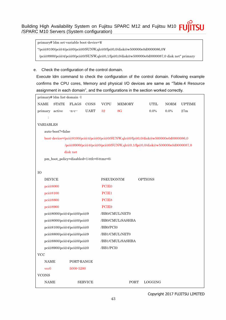
primary# ldm set-variable boot-device=¥
"/pci@8100/pci@4/pci@0/pci@0/SUNW,qlc@0/fp@0,0/disk@w500000e0d0000086,0¥
/pci@8900/pci@4/pci@0/pci@0/SUNW,qlc@0,1/fp@0,0/disk@w500000e0d0000087,0 disk net" primary
e. Check the configuration of the control domain.
Execute ldm command to check the configuration of the control domain. Following example
confirms the CPU cores, Memory and physical I/O devices are same as “Table.4 Resource
assignment in each domain”, and the configurations in the section worked correctly.
primary# ldm list-domain -l
NAME STATE FLAGS CONS VCPU MEMORY UTIL NORM UPTIME
primary active -n-c-- UART 32 8G 0.0% 0.0% 27m
:
VARIABLES
auto-boot?=false
boot-device=/pci@8100/pci@4/pci@0/pci@0/SUNW,qlc@0/fp@0,0/disk@w500000e0d0000086,0
/pci@8900/pci@4/pci@0/pci@0/SUNW,qlc@0,1/fp@0,0/disk@w500000e0d0000087,0
disk net
pm_boot_policy=disabled=1;ttfc=0;ttmr=0;
IO
DEVICE PSEUDONYM OPTIONS
pci@8000 PCIE0
pci@8100 PCIE1
pci@8800 PCIE8
pci@8900 PCIE9
pci@8000/pci@4/pci@0/pci@9 /BB0/CMUL/NET0
pci@8000/pci@4/pci@0/pci@0 /BB0/CMUL/SASHBA
pci@8100/pci@4/pci@0/pci@0 /BB0/PCI0
pci@8800/pci@4/pci@0/pci@9 /BB1/CMUL/NET0
pci@8800/pci@4/pci@0/pci@0 /BB1/CMUL/SASHBA
pci@8900/pci@4/pci@0/pci@0 /BB1/PCI0
VCC
NAME PORT-RANGE
vcc0 5000-5200
VCONS
NAME SERVICE PORT LOGGING
Building High Availability System on Fujitsu SPARC M12 and Fujitsu M10 /SPARC M10 Servers (System configuration)
Copyright 2017 FUJITSU LIMITED 44
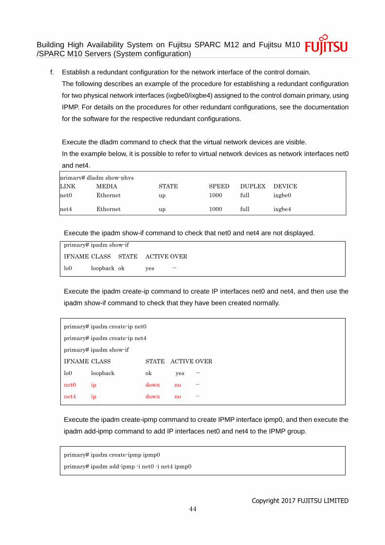
f. Establish a redundant configuration for the network interface of the control domain.
The following describes an example of the procedure for establishing a redundant configuration
for two physical network interfaces (ixgbe0/ixgbe4) assigned to the control domain primary, using
IPMP. For details on the procedures for other redundant configurations, see the documentation
for the software for the respective redundant configurations.
Execute the dladm command to check that the virtual network devices are visible.
In the example below, it is possible to refer to virtual network devices as network interfaces net0
and net4.
primary# dladm show-phys
LINK MEDIA STATE SPEED DUPLEX DEVICE
net0 Ethernet up 1000 full ixgbe0
net4 Ethernet up 1000 full ixgbe4
Execute the ipadm show-if command to check that net0 and net4 are not displayed.
primary# ipadm show-if
IFNAME CLASS STATE ACTIVE OVER
lo0 loopback ok yes --
Execute the ipadm create-ip command to create IP interfaces net0 and net4, and then use the
ipadm show-if command to check that they have been created normally.
primary# ipadm create-ip net0
primary# ipadm create-ip net4
primary# ipadm show-if
IFNAME CLASS STATE ACTIVE OVER
lo0 loopback ok yes --
net0 ip down no --
net4 ip down no --
Execute the ipadm create-ipmp command to create IPMP interface ipmp0, and then execute the
ipadm add-ipmp command to add IP interfaces net0 and net4 to the IPMP group.
primary# ipadm create-ipmp ipmp0
primary# ipadm add-ipmp -i net0 -i net4 ipmp0
Building High Availability System on Fujitsu SPARC M12 and Fujitsu M10 /SPARC M10 Servers (System configuration)
Copyright 2017 FUJITSU LIMITED 45
Execute the ipadm create-addr command to assign an IP address to IPMP interface ipmp0, and
then use the ipadm show-addr command to check the setting. In the example below, a fixed IP
address is assigned.
primary# ipadm create-addr -T static -a local=192.168.1.101/24 ipmp0/v4
primary# ipadm show-addr
ADDR OBJ TYPE STATE ADDR
lo0/v4 static ok 127.0.0.1/8
ipmp0/v4 static ok 192.168.1.101/24
lo0/v6 static ok ::1/128
Execute the ipadm set-ifprop command to set a standby interface, and use the ipmpstat -i
command to check the IPMP configuration.
primary# ipadm set-ifprop -p standby=on -m ip net4
primary# ipmpstat -i
INTERFACE ACTIVE GROUP FLAGS LINK PROBE STATE
net4 no ipmp0 is----- up disabled ok
net0 yes ipmp0 --mbM-- up disabled ok
g. Create a root domain.
This item describes the procedure for creating a root domain.
Execute the ldm add-domain command to add a logical domain named root-dom0.
primary# ldm add-domain root-dom0
Execute the ldm set-variable command to change OpenBoot PROM environment variable "auto-
boot?", which is designed to automatically boot the OS, to "false"(disabled). By default, this
setting is "true" (enabled). So, OpenBoot PROM tries to start the OS automatically when Oracle
Solaris is not installed. Changing this setting to disabled facilitates the work to be performed
before Oracle Solaris installation.
primary# ldm set-variable auto-boot¥?=false root-dom0
First, assign the CPU cores with the ldm set-core command and then assign the memory with
the ldm set-memory command.

Building High Availability System on Fujitsu SPARC M12 and Fujitsu M10 /SPARC M10 Servers (System configuration)
Copyright 2017 FUJITSU LIMITED 46
The following example assigns 10 CPU cores with the ldm set-core command and 52 GB of
memory with the ldm set-memory command, according to the configuration example.
primary# ldm set-core 10 root-dom0
primary# ldm set-memory 52G root-dom0
Note - We recommend that you first configure the CPU cores with the ldm set-core command
and then the memory with the ldm set-memory command. This facilitates the assignment of a
continuous area of collective memory. For details on the CPU core and memory placement
conditions, see "Placement of CPU cores and memory" in "2.5.2 Considerations when operating
the system for dynamic reconfiguration." in the Fujitsu SPARC M12 and Fujitsu M10/SPARC M10
Domain Configuration Guide.
Execute the ldm set-vconsole command to assign the virtual console (vconsole).
The following example executes the ldm set-vconsole command to assign port number 5000 of
the service (vcc0) of the virtual console terminal concentrator in the control domain to the virtual
console.
primary# ldm set-vconsole service=vcc0 port=5000 root-dom0
The following example executes the ldm list-io -l command to display the PCI assignment status.
NAME begins with "/BB0." The "PCIE" line in the [TYPE] column means the PCle endpoint on
the system board 00-0. The line in which the [DOMAIN] column is empty indicates an unassigned
PCIe endpoint and the related root complex is displayed in the [BUS] column.
Therefore, you can quickly understand that PCIE2, PCIE6, PCIE10 and PCIE14 are unassigned
root complexes.
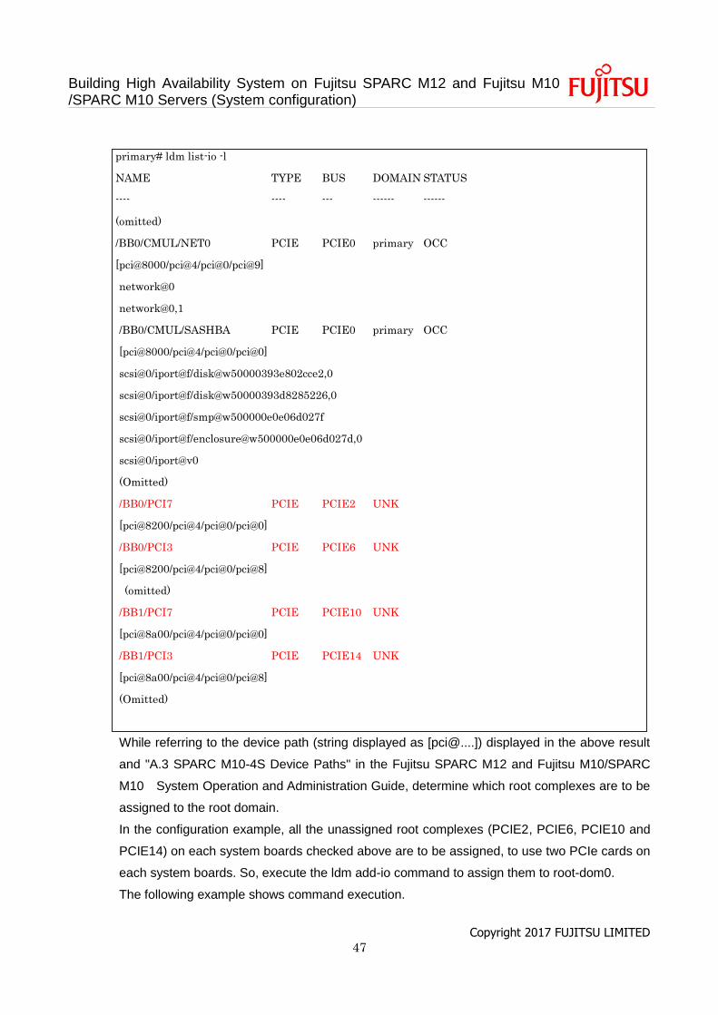
Building High Availability System on Fujitsu SPARC M12 and Fujitsu M10 /SPARC M10 Servers (System configuration)
Copyright 2017 FUJITSU LIMITED 47
primary# ldm list-io -l
NAME TYPE BUS DOMAIN STATUS
---- ---- --- ------ ------
(omitted)
/BB0/CMUL/NET0 PCIE PCIE0 primary OCC
[pci@8000/pci@4/pci@0/pci@9]
network@0
network@0,1
/BB0/CMUL/SASHBA PCIE PCIE0 primary OCC
[pci@8000/pci@4/pci@0/pci@0]
scsi@0/iport@f/disk@w50000393e802cce2,0
scsi@0/iport@f/disk@w50000393d8285226,0
scsi@0/iport@f/smp@w500000e0e06d027f
scsi@0/iport@f/enclosure@w500000e0e06d027d,0
scsi@0/iport@v0
(Omitted)
/BB0/PCI7 PCIE PCIE2 UNK
[pci@8200/pci@4/pci@0/pci@0]
/BB0/PCI3 PCIE PCIE6 UNK
[pci@8200/pci@4/pci@0/pci@8]
(omitted)
/BB1/PCI7 PCIE PCIE10 UNK
[pci@8a00/pci@4/pci@0/pci@0]
/BB1/PCI3 PCIE PCIE14 UNK
[pci@8a00/pci@4/pci@0/pci@8]
(Omitted)
While referring to the device path (string displayed as [pci@....]) displayed in the above result
and "A.3 SPARC M10-4S Device Paths" in the Fujitsu SPARC M12 and Fujitsu M10/SPARC
M10 System Operation and Administration Guide, determine which root complexes are to be
assigned to the root domain.
In the configuration example, all the unassigned root complexes (PCIE2, PCIE6, PCIE10 and
PCIE14) on each system boards checked above are to be assigned, to use two PCIe cards on
each system boards. So, execute the ldm add-io command to assign them to root-dom0.
The following example shows command execution.
Building High Availability System on Fujitsu SPARC M12 and Fujitsu M10 /SPARC M10 Servers (System configuration)
Copyright 2017 FUJITSU LIMITED 48
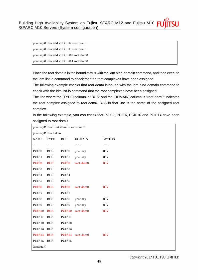
primary# ldm add-io PCIE2 root-dom0
primary# ldm add-io PCIE6 root-dom0
primary# ldm add-io PCIE10 root-dom0
primary# ldm add-io PCIE14 root-dom0
Place the root domain in the bound status with the ldm bind-domain command, and then execute
the ldm list-io command to check that the root complexes have been assigned.
The following example checks that root-dom0 is bound with the ldm bind-domain command to
check with the ldm list-io command that the root complexes have been assigned.
The line where the [TYPE] column is "BUS" and the [DOMAIN] column is "root-dom0" indicates
the root complex assigned to root-dom0. BUS in that line is the name of the assigned root
complex.
In the following example, you can check that PCIE2, PCIE6, PCIE10 and PCIE14 have been
assigned to root-dom0.
primary# ldm bind-domain root-dom0
primary# ldm list-io
NAME TYPE BUS DOMAIN STATUS
---- ---- --- ------ ------
PCIE0 BUS PCIE0 primary IOV
PCIE1 BUS PCIE1 primary IOV
PCIE2 BUS PCIE2 root-dom0 IOV
PCIE3 BUS PCIE3
PCIE4 BUS PCIE4
PCIE5 BUS PCIE5
PCIE6 BUS PCIE6 root-dom0 IOV
PCIE7 BUS PCIE7
PCIE8 BUS PCIE8 primary IOV
PCIE9 BUS PCIE9 primary IOV
PCIE10 BUS PCIE10 root-dom0 IOV
PCIE11 BUS PCIE11
PCIE12 BUS PCIE12
PCIE13 BUS PCIE13
PCIE14 BUS PCIE14 root-dom0 IOV
PCIE15 BUS PCIE15
(Omitted)
Building High Availability System on Fujitsu SPARC M12 and Fujitsu M10 /SPARC M10 Servers (System configuration)
Copyright 2017 FUJITSU LIMITED 49
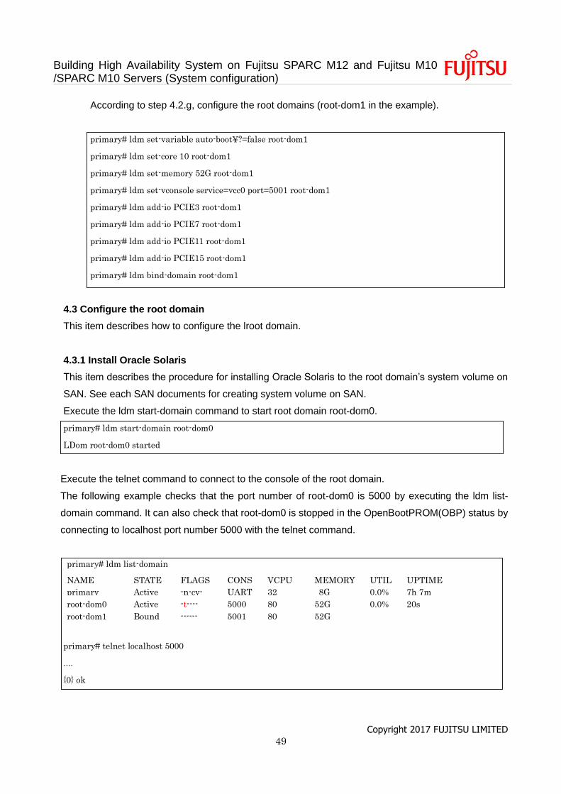
According to step 4.2.g, configure the root domains (root-dom1 in the example).
primary# ldm set-variable auto-boot¥?=false root-dom1
primary# ldm set-core 10 root-dom1
primary# ldm set-memory 52G root-dom1
primary# ldm set-vconsole service=vcc0 port=5001 root-dom1
primary# ldm add-io PCIE3 root-dom1
primary# ldm add-io PCIE7 root-dom1
primary# ldm add-io PCIE11 root-dom1
primary# ldm add-io PCIE15 root-dom1
primary# ldm bind-domain root-dom1
4.3 Configure the root domain
This item describes how to configure the lroot domain.
4.3.1 Install Oracle Solaris
This item describes the procedure for installing Oracle Solaris to the root domain’s system volume on
SAN. See each SAN documents for creating system volume on SAN.
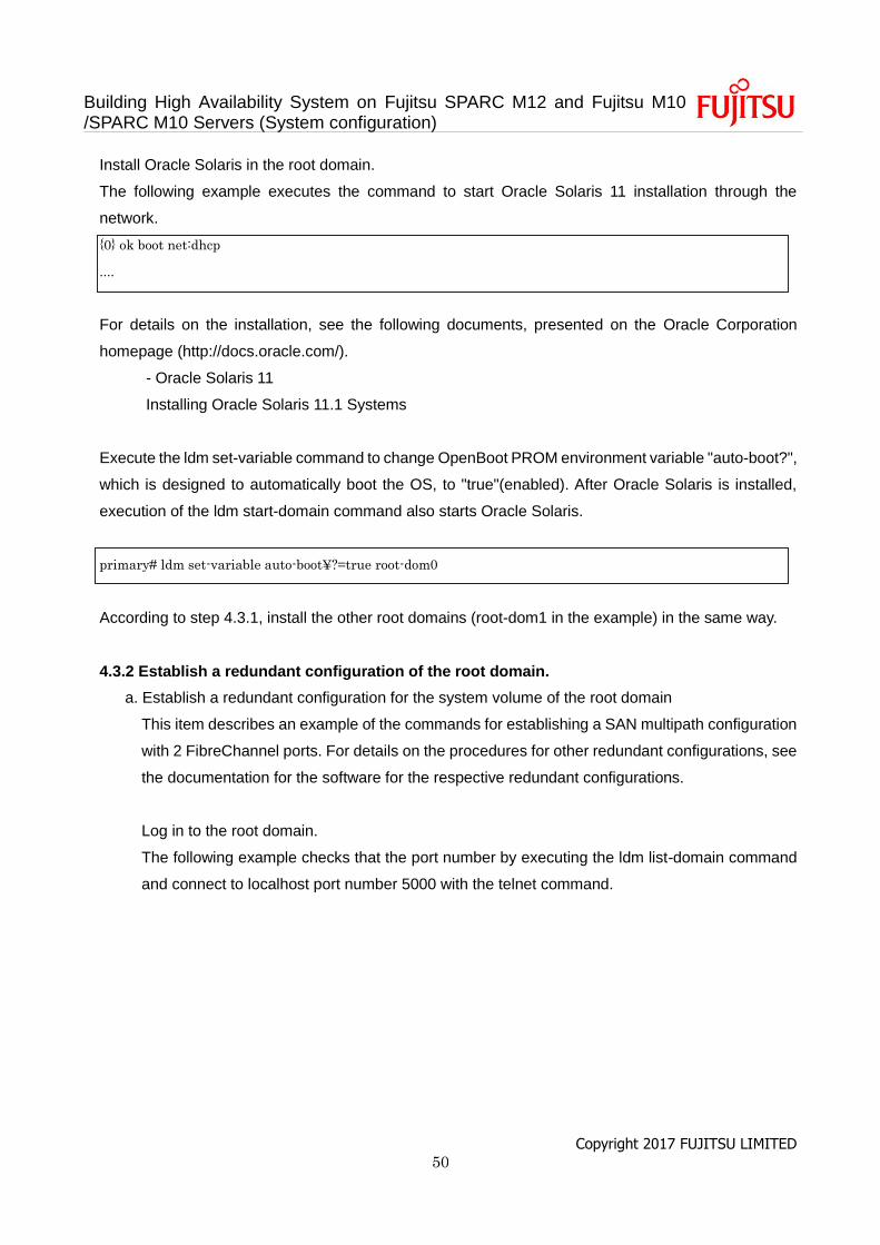
Execute the ldm start-domain command to start root domain root-dom0.
primary# ldm start-domain root-dom0
LDom root-dom0 started
Execute the telnet command to connect to the console of the root domain.
The following example checks that the port number of root-dom0 is 5000 by executing the ldm list-
domain command. It can also check that root-dom0 is stopped in the OpenBootPROM(OBP) status by
connecting to localhost port number 5000 with the telnet command.
primary# ldm list-domain
NAME STATE FLAGS CONS VCPU MEMORY UTIL UPTIME
primary Active -n-cv- UART 32 8G 0.0% 7h 7m
root-dom0 Active -t---- 5000 80 52G 0.0% 20s
root-dom1 Bound ------ 5001 80 52G
primary# telnet localhost 5000
....
{0} ok
Building High Availability System on Fujitsu SPARC M12 and Fujitsu M10 /SPARC M10 Servers (System configuration)
Copyright 2017 FUJITSU LIMITED 50
Install Oracle Solaris in the root domain.
The following example executes the command to start Oracle Solaris 11 installation through the
network.
{0} ok boot net:dhcp
....
For details on the installation, see the following documents, presented on the Oracle Corporation
homepage (http://docs.oracle.com/).
- Oracle Solaris 11
Installing Oracle Solaris 11.1 Systems
Execute the ldm set-variable command to change OpenBoot PROM environment variable "auto-boot?",
which is designed to automatically boot the OS, to "true"(enabled). After Oracle Solaris is installed,
execution of the ldm start-domain command also starts Oracle Solaris.
primary# ldm set-variable auto-boot¥?=true root-dom0
According to step 4.3.1, install the other root domains (root-dom1 in the example) in the same way.
4.3.2 Establish a redundant configuration of the root domain.
a. Establish a redundant configuration for the system volume of the root domain
This item describes an example of the commands for establishing a SAN multipath configuration
with 2 FibreChannel ports. For details on the procedures for other redundant configurations, see
the documentation for the software for the respective redundant configurations.
Log in to the root domain.
The following example checks that the port number by executing the ldm list-domain command
and connect to localhost port number 5000 with the telnet command.
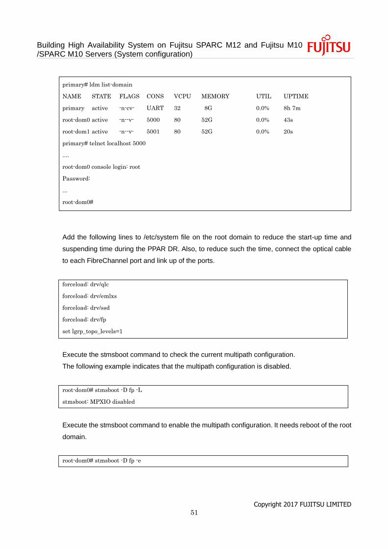
Building High Availability System on Fujitsu SPARC M12 and Fujitsu M10 /SPARC M10 Servers (System configuration)
Copyright 2017 FUJITSU LIMITED 51
primary# ldm list-domain
NAME STATE FLAGS CONS VCPU MEMORY UTIL UPTIME
primary active -n-cv- UART 32 8G 0.0% 8h 7m
root-dom0 active -n--v- 5000 80 52G 0.0% 43s
root-dom1 active -n--v- 5001 80 52G 0.0% 20s
primary# telnet localhost 5000
....
root-dom0 console login: root
Password:
...
root-dom0#
Add the following lines to /etc/system file on the root domain to reduce the start-up time and
suspending time during the PPAR DR. Also, to reduce such the time, connect the optical cable
to each FibreChannel port and link up of the ports.
forceload: drv/qlc
forceload: drv/emlxs
forceload: drv/ssd
forceload: drv/fp
set lgrp_topo_levels=1
Execute the stmsboot command to check the current multipath configuration.
The following example indicates that the multipath configuration is disabled.
root-dom0# stmsboot -D fp -L
stmsboot: MPXIO disabled
Execute the stmsboot command to enable the multipath configuration. It needs reboot of the root
domain.
root-dom0# stmsboot -D fp -e
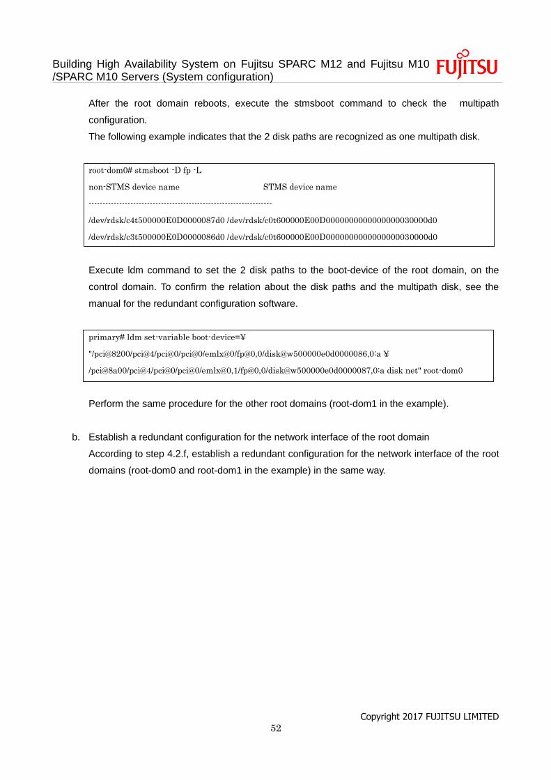
Building High Availability System on Fujitsu SPARC M12 and Fujitsu M10 /SPARC M10 Servers (System configuration)
Copyright 2017 FUJITSU LIMITED 52
After the root domain reboots, execute the stmsboot command to check the multipath
configuration.
The following example indicates that the 2 disk paths are recognized as one multipath disk.
root-dom0# stmsboot -D fp -L
non-STMS device name STMS device name
------------------------------------------------------------------
/dev/rdsk/c4t500000E0D0000087d0 /dev/rdsk/c0t600000E00D0000000000000000030000d0
/dev/rdsk/c3t500000E0D0000086d0 /dev/rdsk/c0t600000E00D0000000000000000030000d0
Execute ldm command to set the 2 disk paths to the boot-device of the root domain, on the
control domain. To confirm the relation about the disk paths and the multipath disk, see the
manual for the redundant configuration software.
primary# ldm set-variable boot-device=¥
"/pci@8200/pci@4/pci@0/pci@0/emlx@0/fp@0,0/disk@w500000e0d0000086,0:a ¥
/pci@8a00/pci@4/pci@0/pci@0/emlx@0,1/fp@0,0/disk@w500000e0d0000087,0:a disk net" root-dom0
Perform the same procedure for the other root domains (root-dom1 in the example).
b. Establish a redundant configuration for the network interface of the root domain
According to step 4.2.f, establish a redundant configuration for the network interface of the root
domains (root-dom0 and root-dom1 in the example) in the same way.
Building High Availability System on Fujitsu SPARC M12 and Fujitsu M10 /SPARC M10 Servers (System configuration)
Copyright 2017 FUJITSU LIMITED 53
5. Configure of the high consolidation type
This chapter explains the configuration procedure of the high consolidation type.
5.1 Install Oracle Solaris and Oracle VM Server for SPARC
Install Oracle Solaris and Oracle VM Server for SPARC on the control domain.
For details on the versions and conditions of Oracle Solaris and Oracle VM Server for SPARC required
for BB HA, see “Building a High Availability System on Fujitsu SPARC M12 and Fujitsu M10/SPARC
M10 Servers (overview)”.
For details on the installation, see the following documents, presented on the Oracle Corporation
website (http://docs.oracle.com/).
- Oracle Solaris 11
Installing Oracle Solaris 11.2 Systems
- Oracle VM Server for SPARC
"Installing and Enabling Software" in the Oracle VM Server for SPARC Administration Guide
5.2 Configure the logical domain(s)
This item describes how to configure the logical domains defined in "Table.5 Resource assignment of
each domain in high consolidation type."
a. Release the control domain resources.
In the factory-default configuration, all the CPU cores, memory, and the PCIe root complexes are
assigned to the control domain (primary). To allow these resources to be assigned to other logical
domains, release some of the resources from the control domain.
Execute the ldm start-reconf command to switch to delayed reconfiguration mode.
primary# ldm start-reconf primary
Initiating a delayed reconfiguration operation on the primary domain.
All configuration changes for other domains are disabled until the primary
domain reboots, at which time the new configuration for the primary domain
will also take effect.
Execute the ldm set-core command and ldm set-memory command to reduce the number of
CPU cores and memory allocated to the control domain.
The following example sets CPU core of the control domain to 6 according to the configuration
example, sets the memory size to 48GB, and reboots Oracle Solaris.
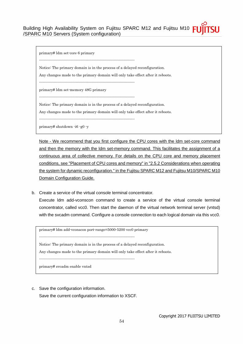
Building High Availability System on Fujitsu SPARC M12 and Fujitsu M10 /SPARC M10 Servers (System configuration)
Copyright 2017 FUJITSU LIMITED 54
primary# ldm set-core 6 primary
------------------------------------------------------------------------------
Notice: The primary domain is in the process of a delayed reconfiguration.
Any changes made to the primary domain will only take effect after it reboots.
------------------------------------------------------------------------------
primary# ldm set-memory 48G primary
------------------------------------------------------------------------------
Notice: The primary domain is in the process of a delayed reconfiguration.
Any changes made to the primary domain will only take effect after it reboots.
------------------------------------------------------------------------------
primary# shutdown -i6 -g0 -y
Note - We recommend that you first configure the CPU cores with the ldm set-core command
and then the memory with the ldm set-memory command. This facilitates the assignment of a
continuous area of collective memory. For details on the CPU core and memory placement
conditions, see "Placement of CPU cores and memory" in "2.5.2 Considerations when operating
the system for dynamic reconfiguration." in the Fujitsu SPARC M12 and Fujitsu M10/SPARC M10
Domain Configuration Guide.
b. Create a service of the virtual console terminal concentrator.
Execute ldm add-vconscon command to create a service of the virtual console terminal
concentrator, called vcc0. Then start the daemon of the virtual network terminal server (vntsd)
with the svcadm command. Configure a console connection to each logical domain via this vcc0.
primary# ldm add-vconscon port-range=5000-5200 vcc0 primary
------------------------------------------------------------------------------
Notice: The primary domain is in the process of a delayed reconfiguration.
Any changes made to the primary domain will only take effect after it reboots.
------------------------------------------------------------------------------
primary# svcadm enable vntsd
c. Save the configuration information.
Save the current configuration information to XSCF.
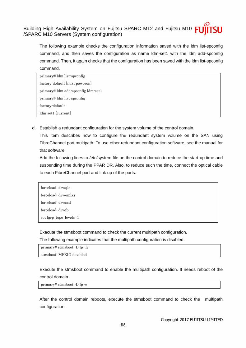
Building High Availability System on Fujitsu SPARC M12 and Fujitsu M10 /SPARC M10 Servers (System configuration)
Copyright 2017 FUJITSU LIMITED 55
The following example checks the configuration information saved with the ldm list-spconfig
command, and then saves the configuration as name ldm-set1 with the ldm add-spconfig
command. Then, it again checks that the configuration has been saved with the ldm list-spconfig
command.
primary# ldm list-spconfig
factory-default [next poweron]
primary# ldm add-spconfig ldm-set1
primary# ldm list-spconfig
factory-default
ldm-set1 [current]
d. Establish a redundant configuration for the system volume of the control domain.
This item describes how to configure the redundant system volume on the SAN using
FibreChannel port multipath. To use other redundant configuration software, see the manual for
that software.
Add the following lines to /etc/system file on the control domain to reduce the start-up time and
suspending time during the PPAR DR. Also, to reduce such the time, connect the optical cable
to each FibreChannel port and link up of the ports.
forceload: drv/qlc
forceload: drv/emlxs
forceload: drv/ssd
forceload: drv/fp
set lgrp_topo_levels=1
Execute the stmsboot command to check the current multipath configuration.
The following example indicates that the multipath configuration is disabled.
primary# stmsboot -D fp -L
stmsboot: MPXIO disabled
Execute the stmsboot command to enable the multipath configuration. It needs reboot of the
control domain.
primary# stmsboot -D fp -e
After the control domain reboots, execute the stmsboot command to check the multipath
configuration.
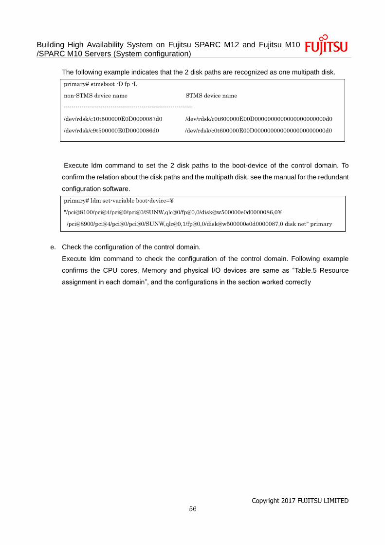
Building High Availability System on Fujitsu SPARC M12 and Fujitsu M10 /SPARC M10 Servers (System configuration)
Copyright 2017 FUJITSU LIMITED 56
The following example indicates that the 2 disk paths are recognized as one multipath disk.
primary# stmsboot -D fp -L
non-STMS device name STMS device name
------------------------------------------------------------------
/dev/rdsk/c10t500000E0D0000087d0 /dev/rdsk/c0t600000E00D0000000000000000000000d0
/dev/rdsk/c9t500000E0D0000086d0 /dev/rdsk/c0t600000E00D0000000000000000000000d0
Execute ldm command to set the 2 disk paths to the boot-device of the control domain. To
confirm the relation about the disk paths and the multipath disk, see the manual for the redundant
configuration software.
primary# ldm set-variable boot-device=¥
"/pci@8100/pci@4/pci@0/pci@0/SUNW,qlc@0/fp@0,0/disk@w500000e0d0000086,0¥
/pci@8900/pci@4/pci@0/pci@0/SUNW,qlc@0,1/fp@0,0/disk@w500000e0d0000087,0 disk net" primary
e. Check the configuration of the control domain.
Execute ldm command to check the configuration of the control domain. Following example
confirms the CPU cores, Memory and physical I/O devices are same as “Table.5 Resource
assignment in each domain”, and the configurations in the section worked correctly
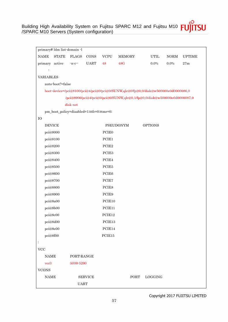
Building High Availability System on Fujitsu SPARC M12 and Fujitsu M10 /SPARC M10 Servers (System configuration)
Copyright 2017 FUJITSU LIMITED 57
primary# ldm list-domain -l
NAME STATE FLAGS CONS VCPU MEMORY UTIL NORM UPTIME
primary active -n-c-- UART 48 48G 0.0% 0.0% 27m
:
VARIABLES
auto-boot?=false
boot-device=/pci@8100/pci@4/pci@0/pci@0/SUNW,qlc@0/fp@0,0/disk@w500000e0d0000086,0
/pci@8900/pci@4/pci@0/pci@0/SUNW,qlc@0,1/fp@0,0/disk@w500000e0d0000087,0
disk net
pm_boot_policy=disabled=1;ttfc=0;ttmr=0;
IO
DEVICE PSEUDONYM OPTIONS
pci@8000 PCIE0
pci@8100 PCIE1
pci@8200 PCIE2
pci@8300 PCIE3
pci@8400 PCIE4
pci@8500 PCIE5
pci@8600 PCIE6
pci@8700 PCIE7
pci@8800 PCIE8
pci@8900 PCIE9
pci@8a00 PCIE10
pci@8b00 PCIE11
pci@8c00 PCIE12
pci@8d00 PCIE13
pci@8e00 PCIE14
pci@8f00 PCIE15
:
VCC
NAME PORT-RANGE
vcc0 5000-5200
VCONS
NAME SERVICE PORT LOGGING
UART
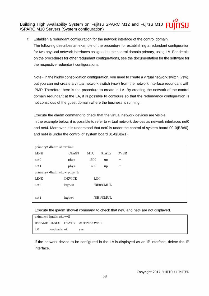
Building High Availability System on Fujitsu SPARC M12 and Fujitsu M10 /SPARC M10 Servers (System configuration)
Copyright 2017 FUJITSU LIMITED 58
f. Establish a redundant configuration for the network interface of the control domain.
The following describes an example of the procedure for establishing a redundant configuration
for two physical network interfaces assigned to the control domain primary, using LA. For details
on the procedures for other redundant configurations, see the documentation for the software for
the respective redundant configurations.
Note - In the highly consolidation configuration, you need to create a virtual network switch (vsw),
but you can not create a virtual network switch (vsw) from the network interface redundant with
IPMP. Therefore, here is the procedure to create in LA. By creating the network of the control
domain redundant at the LA, it is possible to configure so that the redundancy configuration is
not conscious of the guest domain where the business is running.
Execute the dladm command to check that the virtual network devices are visible.
In the example below, it is possible to refer to virtual network devices as network interfaces net0
and net4. Moreover, it is understood that net0 is under the control of system board 00-0(BB#0),
and net4 is under the control of system board 01-0(BB#1).
primary# dladm show-link
LINK CLASS MTU STATE OVER
net0 phys 1500 up --
net4 phys 1500 up --
primary# dladm show-phys -L
LINK DEVICE LOC
net0 ixgbe0 /BB0/CMUL
:
net4 ixgbe4 /BB1/CMUL
Execute the ipadm show-if command to check that net0 and net4 are not displayed.
primary# ipadm show-if
IFNAME CLASS STATE ACTIVE OVER
lo0 loopback ok yes --
If the network device to be configured in the LA is displayed as an IP interface, delete the IP
interface.
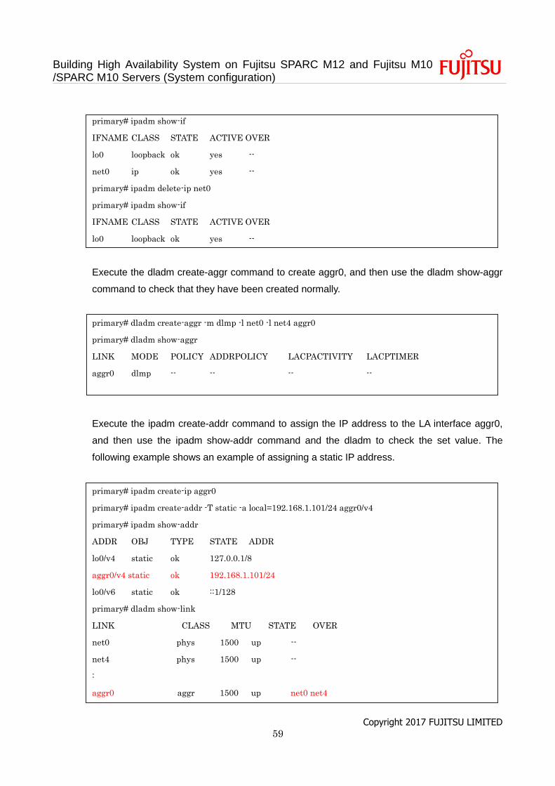
Building High Availability System on Fujitsu SPARC M12 and Fujitsu M10 /SPARC M10 Servers (System configuration)
Copyright 2017 FUJITSU LIMITED 59
primary# ipadm show-if
IFNAME CLASS STATE ACTIVE OVER
lo0 loopback ok yes --
net0 ip ok yes --
primary# ipadm delete-ip net0
primary# ipadm show-if
IFNAME CLASS STATE ACTIVE OVER
lo0 loopback ok yes --
Execute the dladm create-aggr command to create aggr0, and then use the dladm show-aggr
command to check that they have been created normally.
primary# dladm create-aggr -m dlmp -l net0 -l net4 aggr0
primary# dladm show-aggr
LINK MODE POLICY ADDRPOLICY LACPACTIVITY LACPTIMER
aggr0 dlmp -- -- -- --
Execute the ipadm create-addr command to assign the IP address to the LA interface aggr0,
and then use the ipadm show-addr command and the dladm to check the set value. The
following example shows an example of assigning a static IP address.
primary# ipadm create-ip aggr0
primary# ipadm create-addr -T static -a local=192.168.1.101/24 aggr0/v4
primary# ipadm show-addr
ADDR OBJ TYPE STATE ADDR
lo0/v4 static ok 127.0.0.1/8
aggr0/v4 static ok 192.168.1.101/24
lo0/v6 static ok ::1/128
primary# dladm show-link
LINK CLASS MTU STATE OVER
net0 phys 1500 up --
net4 phys 1500 up --
:
aggr0 aggr 1500 up net0 net4

Building High Availability System on Fujitsu SPARC M12 and Fujitsu M10 /SPARC M10 Servers (System configuration)
Copyright 2017 FUJITSU LIMITED 60
g. Create a guest domain.
This item describes the procedure for creating a guest domain.
Execute the ldm add-domain command to add a logical domain named guest0.
primary# ldm add-domain guest0
Execute the ldm set-variable command to change OpenBoot PROM environment variable "auto-
boot?", which is designed to automatically boot the OS, to "false"(disabled). By default, this
setting is "true" (enabled). So, OpenBoot PROM tries to start the OS automatically when Oracle
Solaris is not installed. Changing this setting to disabled facilitates the work to be performed
before Oracle Solaris installation.
primary# ldm set-variable auto-boot¥?=false root-dom0
First, assign the CPU cores with the ldm set-core command and then assign the memory with
the ldm set-memory command.
The following example assigns 6 CPU cores with the ldm set-core command and 32 GB of
memory with the ldm set-memory command, according to the configuration example.
primary# ldm set-core 6 root-dom0
primary# ldm set-memory 32G root-dom0
Note - We recommend that you first configure the CPU cores with the ldm set-core command
and then the memory with the ldm set-memory command. This facilitates the assignment of a
continuous area of collective memory. For details on the CPU core and memory placement
conditions, see "Placement of CPU cores and memory" in "2.5.2 Considerations when operating
the system for dynamic reconfiguration." in the Fujitsu SPARC M12 and Fujitsu M10/SPARC M10
Domain Configuration Guide.
Execute the ldm set-vconsole command to assign the virtual console (vconsole).
The following example executes the ldm set-vconsole command to assign port number 5000 of
the service (vcc0) of the virtual console terminal concentrator in the control domain to the virtual
console.
primary# ldm set-vconsole service=vcc0 port=5000 guest0
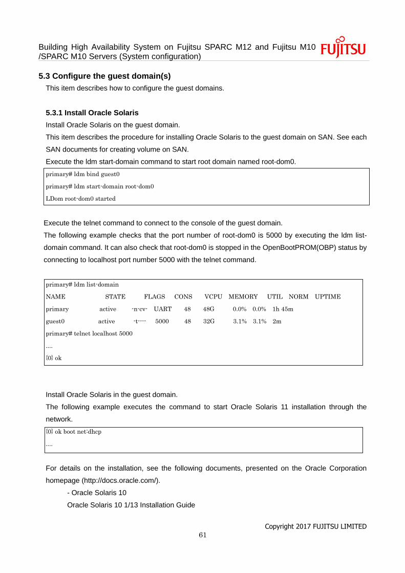
Building High Availability System on Fujitsu SPARC M12 and Fujitsu M10 /SPARC M10 Servers (System configuration)
Copyright 2017 FUJITSU LIMITED 61
5.3 Configure the guest domain(s)
This item describes how to configure the guest domains.
5.3.1 Install Oracle Solaris
Install Oracle Solaris on the guest domain.
This item describes the procedure for installing Oracle Solaris to the guest domain on SAN. See each
SAN documents for creating volume on SAN.
Execute the ldm start-domain command to start root domain named root-dom0.
primary# ldm bind guest0
primary# ldm start-domain root-dom0
LDom root-dom0 started
Execute the telnet command to connect to the console of the guest domain.
The following example checks that the port number of root-dom0 is 5000 by executing the ldm list-
domain command. It can also check that root-dom0 is stopped in the OpenBootPROM(OBP) status by
connecting to localhost port number 5000 with the telnet command.
primary# ldm list-domain
NAME STATE FLAGS CONS VCPU MEMORY UTIL NORM UPTIME
primary active -n-cv- UART 48 48G 0.0% 0.0% 1h 45m
guest0 active -t---- 5000 48 32G 3.1% 3.1% 2m
primary# telnet localhost 5000
....
{0} ok
Install Oracle Solaris in the guest domain.
The following example executes the command to start Oracle Solaris 11 installation through the
network.
{0} ok boot net:dhcp
....
For details on the installation, see the following documents, presented on the Oracle Corporation
homepage (http://docs.oracle.com/).
- Oracle Solaris 10
Oracle Solaris 10 1/13 Installation Guide

Building High Availability System on Fujitsu SPARC M12 and Fujitsu M10 /SPARC M10 Servers (System configuration)
Copyright 2017 FUJITSU LIMITED 62
- Oracle Solaris 11
Installing Oracle Solaris 11.1 Systems
Execute the ldm set-variable command to change OpenBoot PROM environment variable "auto-boot?",
which is designed to automatically boot the OS, to "true"(enabled). After Oracle Solaris is installed,
execution of the ldm start-domain command also starts Oracle Solaris.
primary# ldm set-variable auto-boot¥?=true root-dom0
According to step 5.3.1, install the other guest domains (guest1 and guest2 in the example) in the same
way.
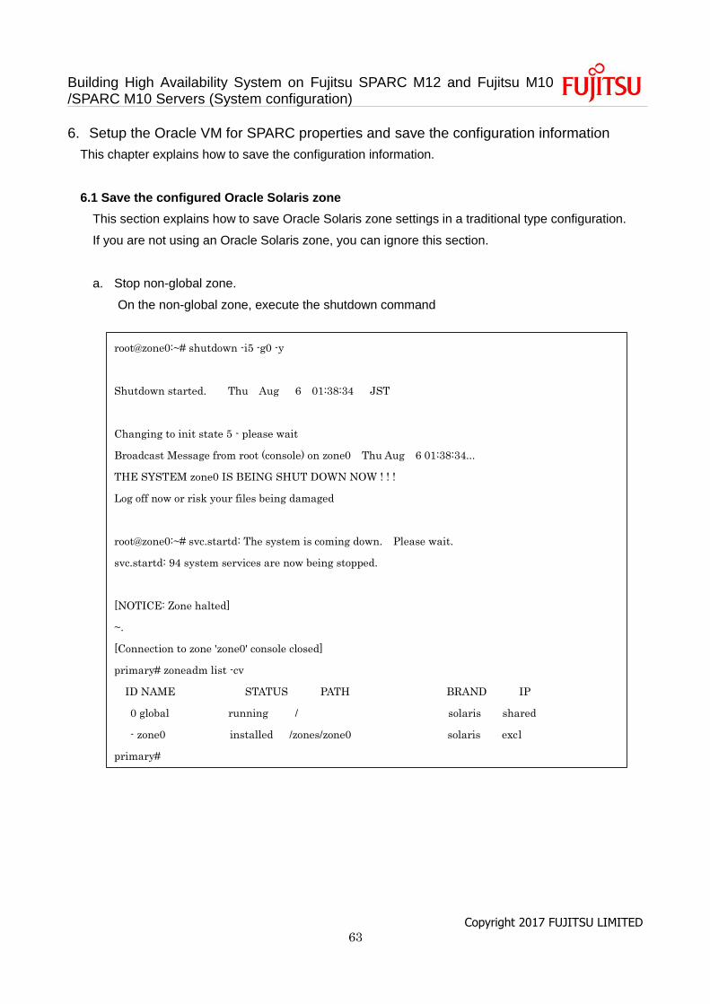
Building High Availability System on Fujitsu SPARC M12 and Fujitsu M10 /SPARC M10 Servers (System configuration)
Copyright 2017 FUJITSU LIMITED 63
6. Setup the Oracle VM for SPARC properties and save the configuration information
This chapter explains how to save the configuration information.
6.1 Save the configured Oracle Solaris zone
This section explains how to save Oracle Solaris zone settings in a traditional type configuration.
If you are not using an Oracle Solaris zone, you can ignore this section.
a. Stop non-global zone.
On the non-global zone, execute the shutdown command
root@zone0:~# shutdown -i5 -g0 -y
Shutdown started. Thu Aug 6 01:38:34 JST
Changing to init state 5 - please wait
Broadcast Message from root (console) on zone0 Thu Aug 6 01:38:34...
THE SYSTEM zone0 IS BEING SHUT DOWN NOW ! ! !
Log off now or risk your files being damaged
root@zone0:~# svc.startd: The system is coming down. Please wait.
svc.startd: 94 system services are now being stopped.
[NOTICE: Zone halted]
~.
[Connection to zone 'zone0' console closed]
primary# zoneadm list -cv
ID NAME STATUS PATH BRAND IP
0 global running / solaris shared
- zone0 installed /zones/zone0 solaris excl
primary#
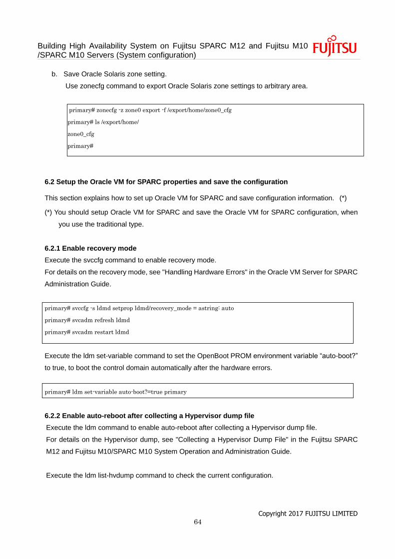
Building High Availability System on Fujitsu SPARC M12 and Fujitsu M10 /SPARC M10 Servers (System configuration)
Copyright 2017 FUJITSU LIMITED 64
b. Save Oracle Solaris zone setting.
Use zonecfg command to export Oracle Solaris zone settings to arbitrary area.
primary# zonecfg -z zone0 export -f /export/home/zone0_cfg
primary# ls /export/home/
zone0_cfg
primary#
6.2 Setup the Oracle VM for SPARC properties and save the configuration
This section explains how to set up Oracle VM for SPARC and save configuration information. (*)
(*) You should setup Oracle VM for SPARC and save the Oracle VM for SPARC configuration, when
you use the traditional type.
6.2.1 Enable recovery mode
Execute the svccfg command to enable recovery mode.
For details on the recovery mode, see "Handling Hardware Errors" in the Oracle VM Server for SPARC
Administration Guide.
primary# svccfg -s ldmd setprop ldmd/recovery_mode = astring: auto
primary# svcadm refresh ldmd
primary# svcadm restart ldmd
Execute the ldm set-variable command to set the OpenBoot PROM environment variable “auto-boot?”
to true, to boot the control domain automatically after the hardware errors.
primary# ldm set-variable auto-boot?=true primary
6.2.2 Enable auto-reboot after collecting a Hypervisor dump file
Execute the ldm command to enable auto-reboot after collecting a Hypervisor dump file.
For details on the Hypervisor dump, see "Collecting a Hypervisor Dump File" in the Fujitsu SPARC
M12 and Fujitsu M10/SPARC M10 System Operation and Administration Guide.
Execute the ldm list-hvdump command to check the current configuration.
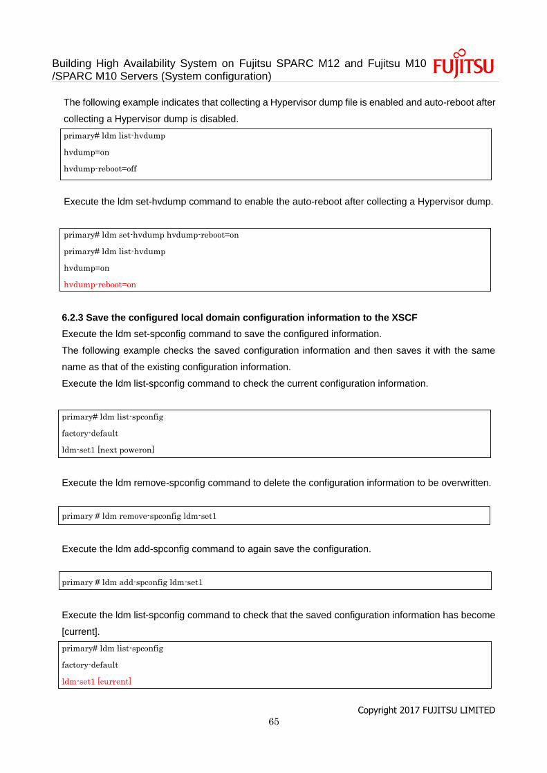
Building High Availability System on Fujitsu SPARC M12 and Fujitsu M10 /SPARC M10 Servers (System configuration)
Copyright 2017 FUJITSU LIMITED 65
The following example indicates that collecting a Hypervisor dump file is enabled and auto-reboot after
collecting a Hypervisor dump is disabled.
primary# ldm list-hvdump
hvdump=on
hvdump-reboot=off
Execute the ldm set-hvdump command to enable the auto-reboot after collecting a Hypervisor dump.
primary# ldm set-hvdump hvdump-reboot=on
primary# ldm list-hvdump
hvdump=on
hvdump-reboot=on
6.2.3 Save the configured local domain configuration information to the XSCF
Execute the ldm set-spconfig command to save the configured information.
The following example checks the saved configuration information and then saves it with the same
name as that of the existing configuration information.
Execute the ldm list-spconfig command to check the current configuration information.
primary# ldm list-spconfig
factory-default
ldm-set1 [next poweron]
Execute the ldm remove-spconfig command to delete the configuration information to be overwritten.
primary # ldm remove-spconfig ldm-set1
Execute the ldm add-spconfig command to again save the configuration.
primary # ldm add-spconfig ldm-set1
Execute the ldm list-spconfig command to check that the saved configuration information has become
[current].
primary# ldm list-spconfig
factory-default
ldm-set1 [current]
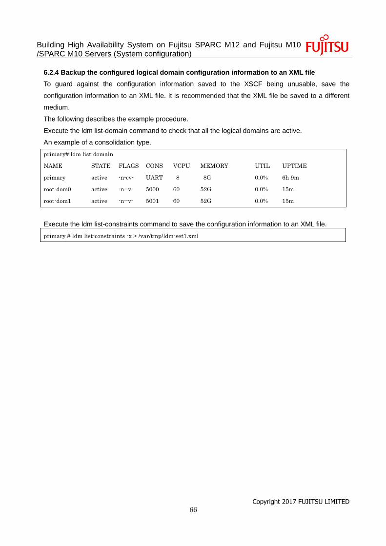
Building High Availability System on Fujitsu SPARC M12 and Fujitsu M10 /SPARC M10 Servers (System configuration)
Copyright 2017 FUJITSU LIMITED 66
6.2.4 Backup the configured logical domain configuration information to an XML file
To guard against the configuration information saved to the XSCF being unusable, save the
configuration information to an XML file. It is recommended that the XML file be saved to a different
medium.
The following describes the example procedure.
Execute the ldm list-domain command to check that all the logical domains are active.
An example of a consolidation type.
primary# ldm list-domain
NAME STATE FLAGS CONS VCPU MEMORY UTIL UPTIME
primary active -n-cv- UART 8 8G 0.0% 6h 9m
root-dom0 active -n--v- 5000 60 52G 0.0% 15m
root-dom1 active -n--v- 5001 60 52G 0.0% 15m
Execute the ldm list-constraints command to save the configuration information to an XML file.
primary # ldm list-constraints -x > /var/tmp/ldm-set1.xml
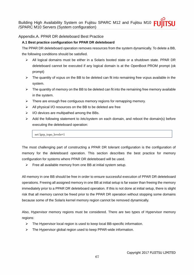
Building High Availability System on Fujitsu SPARC M12 and Fujitsu M10 /SPARC M10 Servers (System configuration)
Copyright 2017 FUJITSU LIMITED 67
Appendix.A. PPAR DR deleteboard Best Practice
A.1 Best practice configuration for PPAR DR deleteboard
The PPAR DR deleteboard operation removes resources from the system dynamically. To delete a BB,
the following conditions should be satisfied.
All logical domains must be either in a Solaris booted state or a shutdown state. PPAR DR
deleteboard cannot be executed if any logical domain is at the OpenBoot PROM prompt (ok
prompt)
The quantity of vcpus on the BB to be deleted can fit into remaining free vcpus available in the
system.
The quantity of memory on the BB to be deleted can fit into the remaining free memory available
in the system.
There are enough free contiguous memory regions for remapping memory.
All physical I/O resources on the BB to be deleted are free
I/O devices are multipathed among the BBs.
Add the following statement to /etc/system on each domain, and reboot the domain(s) before
executing the deleteboard operation:
The most challenging part of constructing a PPAR DR tolerant configuration is the configuration of
memory for the deleteboard operation. This section describes the best practice for memory
configuration for systems where PPAR DR deleteboard will be used.
Free all available memory from one BB at initial system setup.
All memory in one BB should be free in order to ensure successful execution of PPAR DR deleteboard
operations. Freeing all assigned memory in one BB at initial setup is far easier than freeing the memory
immediately prior to a PPAR DR deleteboard operation. If this is not done at initial setup, there is slight
risk that all memory cannot be freed prior to the PPAR DR operation without stopping some domains
because some of the Solaris kernel memory region cannot be removed dynamically.
Also, Hypervisor memory regions must be considered. There are two types of Hypervisor memory
regions:
The Hypervisor local region is used to keep local BB-specific information.
The Hypervisor global region used to keep PPAR-wide information.
set lgrp_topo_levels=1
Building High Availability System on Fujitsu SPARC M12 and Fujitsu M10 /SPARC M10 Servers (System configuration)
Copyright 2017 FUJITSU LIMITED 68
A Hypervisor local region (always 1272MB in size) is located on each BB. A Hypervisor global regions
(always 512MB and 256MB in size) are located on one of the BBs. In the case of a 2BB system, the
Hypervisor global regions are located on the lowest LSB (Logical System Board) at initial configuration.
The user can confirm the Hypervisor regions by executing the “ldm list-devices -a” command.
Hypervisor regions are displayed as “_sys_”. In a PPAR DR deleteboard operation, the Hypervisor local
region on the BB to be deleted is discarded, and the Hypervisor global region on the BB to be deleted
is remapped to the remaining BB. The system must have sufficient free memory on the remaining BB
for the remapped Hypervisor global regions if the BB to be deleted contains the Hypervisor global
regions.
The following example shows the memory usage on a 2BB system. The memory on BB#1
(PA:0x700000000000 - / SOCKET_ID 4 to 6) is free except for the Hypervisor local region (1272MB
_sys_ region). The memory on BB#0 (PA:0x780000000000 - / SOCKET_ID 0 to 2) is used by the
primary, ldom1 to ldom3, and the Hypervisor local/global region (1272MB, 512MB, 256MB _sys_
region), with no free memory. The Hypervisor global region (512MB and 256MB _sys_ region) is also
remapped by OVM automatically in a PPAR DR deleteboard operation, and freeing all memory on
BB#1 is the preferred way to avoid complicated remapping considerations. In this configuration, PPAR
DR deleteboard will succeed since BB#1 has enough free memory for remapping the Hypervisor global
regions when BB#0 is replaced. The Hypervisor local region on the BB to be deleted is automatically
removed after the PPAR DR deleteboard is executed. The Hypervisor local region can be ignored when
planning for PPAR DR operations.
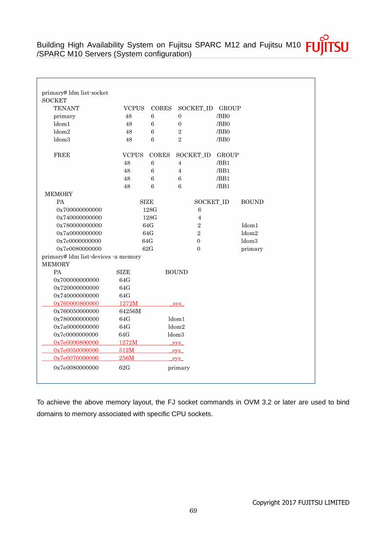
Building High Availability System on Fujitsu SPARC M12 and Fujitsu M10 /SPARC M10 Servers (System configuration)
Copyright 2017 FUJITSU LIMITED 69
To achieve the above memory layout, the FJ socket commands in OVM 3.2 or later are used to bind
domains to memory associated with specific CPU sockets.
primary# ldm list-socket
SOCKET
TENANT VCPUS CORES SOCKET_ID GROUP
primary 48 6 0 /BB0
ldom1 48 6 0 /BB0
ldom2 48 6 2 /BB0
ldom3 48 6 2 /BB0
FREE VCPUS CORES SOCKET_ID GROUP
48 6 4 /BB1
48 6 4 /BB1
48 6 6 /BB1
48 6 6 /BB1
MEMORY
PA SIZE SOCKET_ID BOUND
0x700000000000 128G 6
0x740000000000 128G 4
0x780000000000 64G 2 ldom1
0x7a0000000000 64G 2 ldom2
0x7c0000000000 64G 0 ldom3
0x7e0080000000 62G 0 primary
primary# ldm list-devices -a memory
MEMORY
PA SIZE BOUND
0x700000000000 64G
0x720000000000 64G
0x740000000000 64G
0x760000800000 1272M _sys_
0x760050000000 64256M
0x780000000000 64G ldom1
0x7a0000000000 64G ldom2
0x7c0000000000 64G ldom3
0x7e0000800000 1272M _sys_
0x7e0050000000 512M _sys_
0x7e0070000000 256M _sys_
0x7e0080000000 62G primary
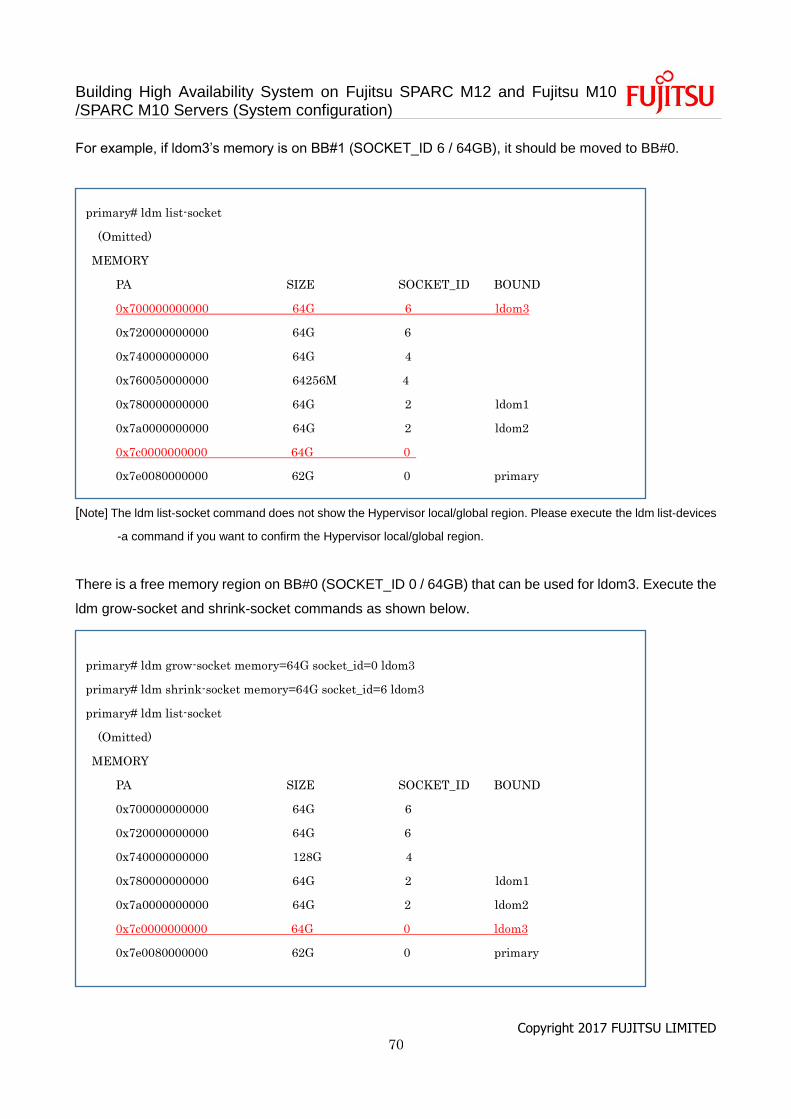
Building High Availability System on Fujitsu SPARC M12 and Fujitsu M10 /SPARC M10 Servers (System configuration)
Copyright 2017 FUJITSU LIMITED 70
For example, if ldom3’s memory is on BB#1 (SOCKET_ID 6 / 64GB), it should be moved to BB#0.
[Note] The ldm list-socket command does not show the Hypervisor local/global region. Please execute the ldm list-devices
-a command if you want to confirm the Hypervisor local/global region.
There is a free memory region on BB#0 (SOCKET_ID 0 / 64GB) that can be used for ldom3. Execute the
ldm grow-socket and shrink-socket commands as shown below.
primary# ldm list-socket
(Omitted)
MEMORY
PA SIZE SOCKET_ID BOUND
0x700000000000 64G 6 ldom3
0x720000000000 64G 6
0x740000000000 64G 4
0x760050000000 64256M 4
0x780000000000 64G 2 ldom1
0x7a0000000000 64G 2 ldom2
0x7c0000000000 64G 0
0x7e0080000000 62G 0 primary
primary# ldm grow-socket memory=64G socket_id=0 ldom3
primary# ldm shrink-socket memory=64G socket_id=6 ldom3
primary# ldm list-socket
(Omitted)
MEMORY
PA SIZE SOCKET_ID BOUND
0x700000000000 64G 6
0x720000000000 64G 6
0x740000000000 128G 4
0x780000000000 64G 2 ldom1
0x7a0000000000 64G 2 ldom2
0x7c0000000000 64G 0 ldom3
0x7e0080000000 62G 0 primary
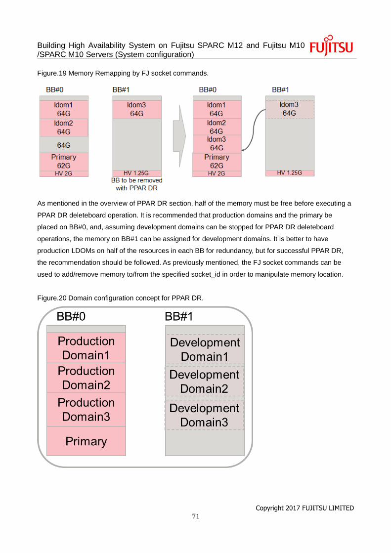
Building High Availability System on Fujitsu SPARC M12 and Fujitsu M10 /SPARC M10 Servers (System configuration)
Copyright 2017 FUJITSU LIMITED 71
Figure.19 Memory Remapping by FJ socket commands.
As mentioned in the overview of PPAR DR section, half of the memory must be free before executing a
PPAR DR deleteboard operation. It is recommended that production domains and the primary be
placed on BB#0, and, assuming development domains can be stopped for PPAR DR deleteboard
operations, the memory on BB#1 can be assigned for development domains. It is better to have
production LDOMs on half of the resources in each BB for redundancy, but for successful PPAR DR,
the recommendation should be followed. As previously mentioned, the FJ socket commands can be
used to add/remove memory to/from the specified socket_id in order to manipulate memory location.
Figure.20 Domain configuration concept for PPAR DR.

Building High Availability System on Fujitsu SPARC M12 and Fujitsu M10 /SPARC M10 Servers (System configuration)
Copyright 2017 FUJITSU LIMITED 72
Revision history
Revision
date
Rev Change
2016.11 1.0 Newly added.
2017.4 2.0 Add the Fujitsu SPARC M12-2S Server
Add configuration pattern