Embed Size (px)
Citation preview
Building VECM-based Systems with a Model
Driven Approach: an Experience Report
Maurizio Leotta, Gianna Reggio, Filippo Ricca, and Egidio Astesiano
Dipartimento di Informatica e Scienze dell’Informazione - DISIUniversita di Genova16146 Genova, Italy
{maurizio.leotta |gianna.reggio |filippo.ricca |astes}@disi.unige.it
Abstract. Recently, we took part in a project with two local companiesabout the creation of a UML-based Model Driven rigorous method todevelop VECM-based systems. VECM is a way to abstract from the detailsof different Enterprise Content Management (ECM) systems used withinthe same organization. This report details the experience made using ourmethod to develop V-Protocol: a system able to protocol, sign and archivepublic competition announcements received by a company.
1 Introduction
The authors have been recently involved in the VirtualECM project1 aimed atdeveloping the VECM technology and a UML-based Model Driven (MD) rigorousmethod for building systems based on VECM. A VECM-based system (shortlyV-System) is a system that uses the VECM software interface (Sect. 2). In anutshell, a VECM abstracts the basic operations offered by an ECM. An ECMis a system used to capture, manage, store, and deliver enterprise content. Itprovides operations on documents such as: createDocument() and deleteDocu-ment(). There are a lot of ECM systems available on the market, e.g., Alfresco(open source), SharePoint (Microsoft), Oracle Content Management (Oracle),and Documentum (EMC).
On the top of this heterogeneous ECM environment, usually, the companiesbuild their systems using several ECM systems characterized by different inter-faces; for example, a bank that uses an ECM system to manage credit transferand another one for loans. Often, the consequence of this practice is the develop-ment of a system highly coupled with the underlying ECM systems. The VECMsoftware interface solves this problem. In practice, the VECM allows to developsystems not tied to the specific characteristics of a particular ECM.
In this paper we propose a UML rigorous method useful to develop VECM-based systems (Sect. 3). It follows the MD approach [2] for the developmentof software systems. In particular, several UML models are created startingfrom the business process model to obtain a detailed design model that can
1 VirtualECM project was supported by “Programma Operativo Regionale POR-FESR(2007-2013)”, Liguria, Italy
MODELS'11 Workshop - EESSMod 2011
- 38 -
2 Maurizio Leotta, Gianna Reggio, Filippo Ricca, and Egidio Astesiano
be transformed/refined in a running system. We have applied this method tobuild V-Protocol, the selected case study for the project, which is a system usedto protocol, sign and archive public competition announcements received by acompany.
2 VECM and ECM
In this section we explain what a VECM is and report on the factors that havemotivated the development of the VECM software interface, which is the aim ofthe VirtualECM project.
There are a lot of ECM systems available on the market. Even if each of themhas some distinguishing features, they provide substantially the same operationsoften called in different ways and with different parameters.
Usually, in a big company it is possible to find different ECM systems chosenby and used in different branches of the same organization. This can happenfor several reasons: for example because different branches of the same companyhave chosen different ECM systems for money matters, licence or specific char-acteristics. Thus, a company often has to build a system in an heterogeneousECM environment using different underlying ECM systems. The result of thispractice is a system that interacts with different ECM systems with their owninterfaces, languages, and characteristics. Systems built in this way are tightlycoupled to the set of used ECM systems, and thus tend to exhibit well-knownproblems (e.g., difficulties in changing, reusing, and testing software).
That problem can be solved with an additional layer of abstraction placedbetween the system and the different ECM systems. Such software layer is calledVECM, a sort of virtualization of ECM systems. In practice, without the VECMa system has to interact with a set of different ECM systems and it has toknow their different interfaces; instead, with the VECM a system has to knowonly the VECM interface. The management of the interaction with the differentunderlying ECM systems is totally delegated to the VECM. When the systemuses a functionality offered by the VECM, it does not to know what type ofECM is actually used. In this way it is possible to replace an ECM with anotherwithout problems.
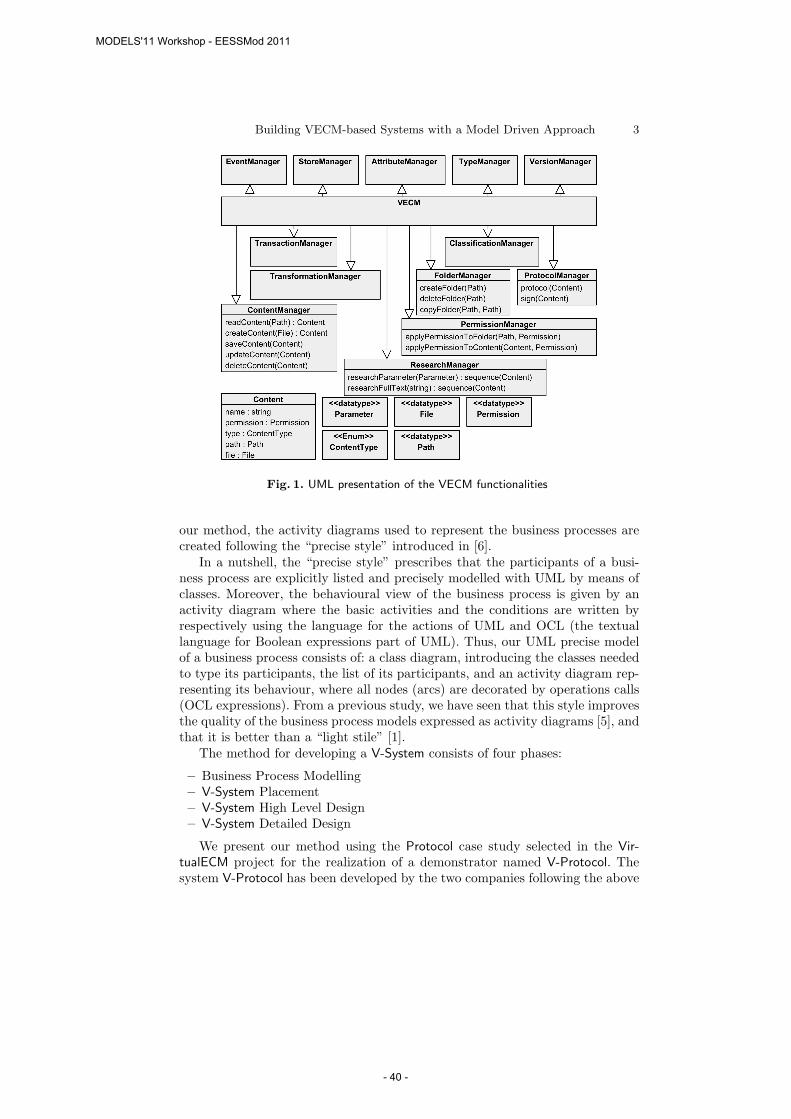
Fig. 1 shows a simplified definition of the functionalities offered by the VECM,which are an abstraction of a well defined subset of operations typically offeredby an ECM. As we can see, the VECM operations cover different areas and workon or produce content.
3 The Method
We propose a method for the development of systems based on the VECM thatfollows the MD approach. The starting point is a UML model representing thetarget business process including at least an activity diagram and the final resultis a detailed design model that can be transformed into a running system. In
MODELS'11 Workshop - EESSMod 2011
- 39 -
Building VECM-based Systems with a Model Driven Approach 3
Fig. 1. UML presentation of the VECM functionalities
our method, the activity diagrams used to represent the business processes arecreated following the “precise style” introduced in [6].
In a nutshell, the “precise style” prescribes that the participants of a busi-ness process are explicitly listed and precisely modelled with UML by means ofclasses. Moreover, the behavioural view of the business process is given by anactivity diagram where the basic activities and the conditions are written byrespectively using the language for the actions of UML and OCL (the textuallanguage for Boolean expressions part of UML). Thus, our UML precise modelof a business process consists of: a class diagram, introducing the classes neededto type its participants, the list of its participants, and an activity diagram rep-resenting its behaviour, where all nodes (arcs) are decorated by operations calls(OCL expressions). From a previous study, we have seen that this style improvesthe quality of the business process models expressed as activity diagrams [5], andthat it is better than a “light stile” [1].
The method for developing a V-System consists of four phases:
– Business Process Modelling– V-System Placement– V-System High Level Design– V-System Detailed Design
We present our method using the Protocol case study selected in the Vir-tualECM project for the realization of a demonstrator named V-Protocol. Thesystem V-Protocol has been developed by the two companies following the above
MODELS'11 Workshop - EESSMod 2011
- 40 -
4 Maurizio Leotta, Gianna Reggio, Filippo Ricca, and Egidio Astesiano
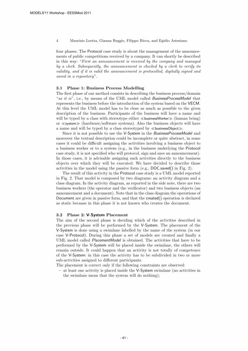
four phases. The Protocol case study is about the management of the announce-ments of public competitions received by a company. It can shortly be describedin this way: “First an announcement is received by the company and managedby a clerk. Subsequently, the announcement is checked by a clerk to verify itsvalidity, and if it is valid the announcement is protocolled, digitally signed andsaved in a repository”.
3.1 Phase 1: Business Process Modelling
The first phase of our method consists in describing the business process/domain“as it is”, i.e., by means of the UML model called BusinessProcessModel thatrepresents the business before the introduction of the system based on the VECM.At this level the UML model has to be close as much as possible to the givendescription of the business. Participants of the business will have a name andwill be typed by a class with stereotype either ≪businessWorker≫ (human being)or ≪system≫ (hardware/software systems). Also the business objects will havea name and will be typed by a class stereotyped by ≪businessObject≫.
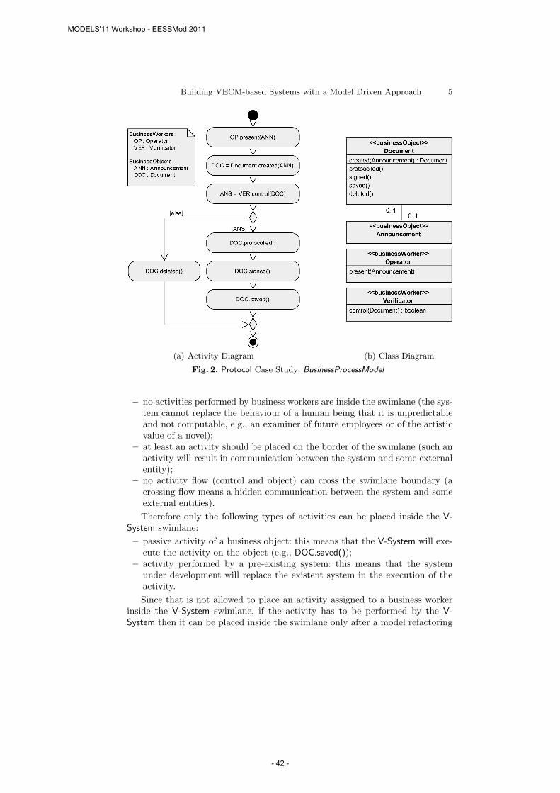
Since it is not possible to use the V-System in the BusinessProcessModel andmoreover the textual description could be incomplete or quite abstract, in somecases it could be difficult assigning the activities involving a business object toa business worker or to a system (e.g., in the business underlying the Protocolcase study, it is not specified who will protocol, sign and save an announcement).In those cases, it is advisable assigning such activities directly to the businessobjects over which they will be executed. We have decided to describe thoseactivities in the model using the passive form (e.g., DOC.saved() in Fig. 2).
The result of this activity in the Protocol case study is a UML model reportedin Fig. 2. That model is composed by two diagrams: an activity diagram and aclass diagram. In the activity diagram, as reported in the side note, there are twobusiness workers (the operator and the verificator) and two business objects (anannouncement and a document). Note that in the class diagram the operations ofDocument are given in passive form, and that the created() operation is declaredas static because in this phase it is not known who creates the document.
3.2 Phase 2: V-System Placement
The aim of the second phase is deciding which of the activities described inthe previous phase will be performed by the V-System. The placement of theV-System is done using a swimlane labelled by the name of the system (in ourcase V-Protocol). During this phase a set of models are created and finally aUML model called PlacementModel is obtained. The activities that have to beperformed by the V-System will be placed inside the swimlane, the others willremain outside. It could happen that an activity is not totally of competenceof the V-System: in this case the activity has to be subdivided in two or moresub-activities assigned to different participants.The placement is correct only if the following constraints are observed:
– at least one activity is placed inside the V-System swimlane (no activities inthe swimlane mean that the system will do nothing);
MODELS'11 Workshop - EESSMod 2011
- 41 -
Building VECM-based Systems with a Model Driven Approach 5
(a) Activity Diagram (b) Class Diagram
Fig. 2. Protocol Case Study: BusinessProcessModel
– no activities performed by business workers are inside the swimlane (the sys-tem cannot replace the behaviour of a human being that it is unpredictableand not computable, e.g., an examiner of future employees or of the artisticvalue of a novel);
– at least an activity should be placed on the border of the swimlane (such anactivity will result in communication between the system and some externalentity);
– no activity flow (control and object) can cross the swimlane boundary (acrossing flow means a hidden communication between the system and someexternal entities).
Therefore only the following types of activities can be placed inside the V-System swimlane:
– passive activity of a business object: this means that the V-System will exe-cute the activity on the object (e.g., DOC.saved());
– activity performed by a pre-existing system: this means that the systemunder development will replace the existent system in the execution of theactivity.
Since that is not allowed to place an activity assigned to a business workerinside the V-System swimlane, if the activity has to be performed by the V-System then it can be placed inside the swimlane only after a model refactoring
MODELS'11 Workshop - EESSMod 2011
- 42 -
6 Maurizio Leotta, Gianna Reggio, Filippo Ricca, and Egidio Astesiano
step in which the activity has to be assigned to a participant stereotyped by≪system≫ (or ≪businessObject≫ using the passive form). This means that thesystem will perform an activity that previously was done by a human.
During the placement of the V-System in presence of constraints violationsthe following cases can occur:
– the placement becomes corrected after performing one or more business pro-cess model refactoring;
– it is not possible to refactor the model to satisfy the constraints; in suchcase the developer has to either change the placement or to conclude thatthe intended system is not doable.
The result of this phase is the PlacementModel , having the form of a Busi-
nessProcessModel where part of the activity diagram is included in one swimlanenamed as the system to develop.
The creation of the PlacementModel (that for space limitations we do notreport here) for V-Protocol has required a model refactoring step in order tocreate the activities for the messages exchange between the participants. Forexample, the activity control(DOC) has been broken in several activities becauseit involve both the operator and the system.
3.3 Phase 3: V-System High Level Design
The goal of this phase is providing a high level design of the V-System with adetailed description of the activities carried out by the system. During this phasea UML model called DesignModel is produced.
We start from the PlacementModel and perform a refinement step. For eachparticipant of type ≪businessWorker≫ and ≪system≫ in the activity diagram weintroduce a swimlane labelled by its name. In this model, the involved partic-ipants communicate using two type of UML actions: – the call action2 ( )used when a participant sends a message to another one and – the accept action( ) used when a participant receives a message from another one.
At this level of description, all the activities in the V-System swimlane arereported as executed by the system as a whole. There are no details about theinner structure of the V-System (e.g., information about the number of ECMused).
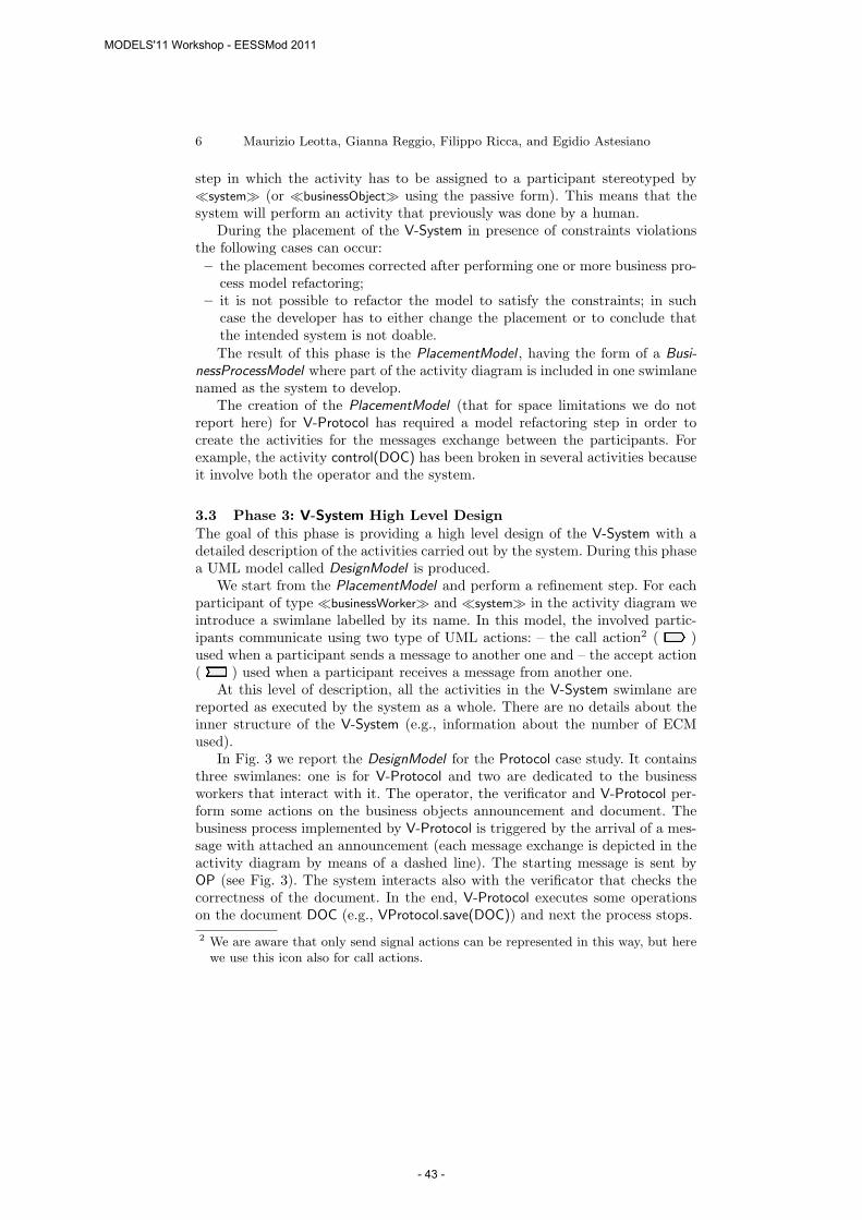
In Fig. 3 we report the DesignModel for the Protocol case study. It containsthree swimlanes: one is for V-Protocol and two are dedicated to the businessworkers that interact with it. The operator, the verificator and V-Protocol per-form some actions on the business objects announcement and document. Thebusiness process implemented by V-Protocol is triggered by the arrival of a mes-sage with attached an announcement (each message exchange is depicted in theactivity diagram by means of a dashed line). The starting message is sent byOP (see Fig. 3). The system interacts also with the verificator that checks thecorrectness of the document. In the end, V-Protocol executes some operationson the document DOC (e.g., VProtocol.save(DOC)) and next the process stops.
2 We are aware that only send signal actions can be represented in this way, but herewe use this icon also for call actions.
MODELS'11 Workshop - EESSMod 2011
- 43 -
Building VECM-based Systems with a Model Driven Approach 7
(a) Activity Diagram
(b) Class Diagram
Fig. 3. Protocol Case Study: DesignModel
In Fig. 3(b), we show the class diagram associated with the activity diagramof Fig. 3(a). The class diagram is used to type and specify the stereotype ofeach participant and to specify attributes and/or operations of each participant.Moreover, the class diagram can contain datatypes (e.g., DigitalSignature) usedto type attributes or operation parameters. The activity diagram created at thislevel ought to be structured [7] because unstructured diagrams make difficult
MODELS'11 Workshop - EESSMod 2011
- 44 -
8 Maurizio Leotta, Gianna Reggio, Filippo Ricca, and Egidio Astesiano
the translation of business process models into executable models (e.g., writtenin BPEL [3]) that often offer structured-programming constructs only.
The models created following our method can be enriched at each phase withother UML diagrams or details that increase the level of information provided;for example in the class diagram in Fig. 3(b) we added some constraints.
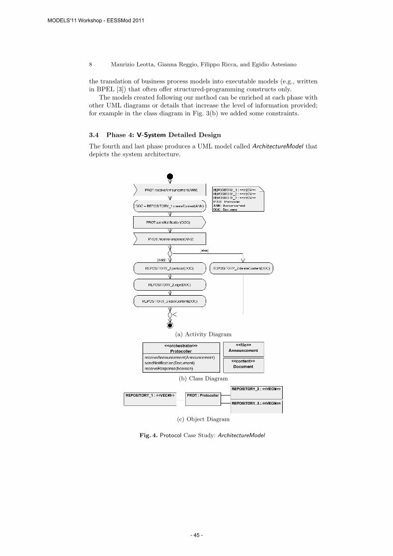
3.4 Phase 4: V-System Detailed Design
The fourth and last phase produces a UML model called ArchitectureModel thatdepicts the system architecture.
(a) Activity Diagram
(b) Class Diagram
(c) Object Diagram
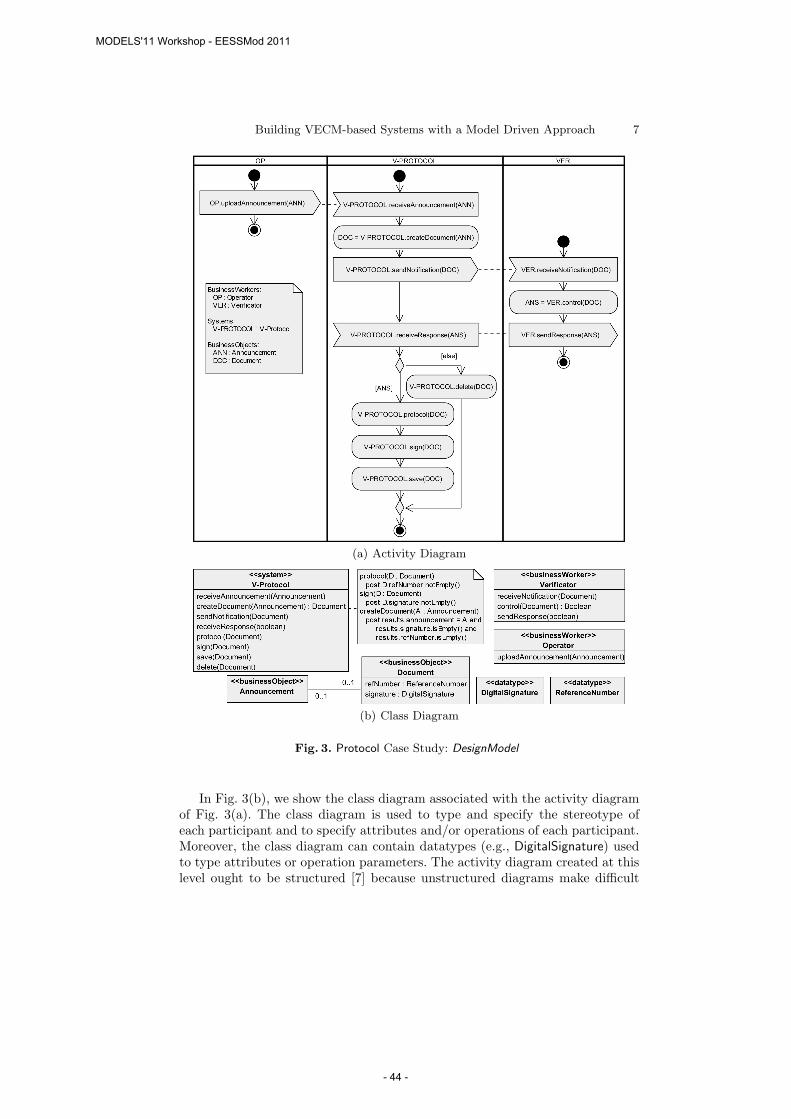
Fig. 4. Protocol Case Study: ArchitectureModel
MODELS'11 Workshop - EESSMod 2011
- 45 -
Building VECM-based Systems with a Model Driven Approach 9
The detailed design is given in terms of the subsystems that constitute thesystem. The subsystems can be: (1) one or more VECMs that abstract the under-lying ECMs; (2) an orchestrator that coordinates the execution of the differentVECMs and, if necessary, performs some data elaborations. Note that all thecomputations not assignable to the VECMs are done by the orchestrator. More-over, the orchestrator manages the interaction with the outside participants (e.g.,sending and receiving messages). At this level, for simplicity, the participants notincluded in the V-System swimlane are removed from the model. The attentionis uniquely focused on the V-System architecture.
The subsystems that are typed by VECM can perform only a predefined setof operations (see Fig. 1). All the operations not supported by VECM have to beexecuted by the orchestrator and if it is not possible they have to be substitutedby calls to external services and this require a modification of the V-Systemdesign.
In Fig. 4 we show the V-Protocol ArchitectureModel . The system is composedby four subsystems: one orchestrator (Protocoller) and three repositories of typeVECM. All the operations performed by the repositories are included in the UMLpresentation of the VECM functionalities in Fig. 1. Note that the repositories donot communicate each other.
4 Lessons Learnt
Based on the experience that we have acquired during the development of ourmethod, we summarize the lessons learnt and discuss opportunities for futureresearch.
– It is possible to apply MD to build VECM-based applications without invest-ing in complex tools and expensive training. It is sufficient a UML designtool (e.g., Visual Paradigm3) and a basic knowledge of UML. In the case ofthe VirtualECM project the involved companies had an adequate expertisefor the execution of the method.
– Usually business process descriptions and models used in practice and givenas starting point to develop a system are ambiguous, inconsistent, over-specific or too generic. Often, models given in “light style” format [6] seemvery simple and easy to understand but often they contain subtle flaws thatcould bring to different interpretations and meanings. Using the “precisestyle” helps to reduce more common errors and flaws [5].
– The use of VECM is complementary to the use of SOA and not an alternative,given that they differ in the level of application. Indeed, VECM can be placedabove a set of SOA-based ECM that though they have a SOA-based interface,the signatures of their operations are not standardized. For this reasons alsoin a SOA-based ECM environment it is useful to adopt VECM. Moreover,VECM exposes a SOA interface so it can be invoked as a web service.
3 a UML modeller covering all kinds of UML diagram types. See http://www.visual-paradigm.com/
MODELS'11 Workshop - EESSMod 2011
- 46 -
10 Maurizio Leotta, Gianna Reggio, Filippo Ricca, and Egidio Astesiano
– Methods for developing ECM based systems are difficult to find. Some toolsthat permit to integrate different ECMs exist (e.g., ECM integration layerof SAP NetWeaver or FusionEnterprise) but they are part of complex tech-nology platforms. Instead VECM is a light interface that does not requirecomplex and expensive solutions.
– The adoption of CMIS4 [4] does not replace the use of VECM. Indeed, evenif CMIS will reach in the future a great diffusion among ECM users, a lot ofcompanies will still use obsolete ECMs.
– Currently, the two companies involved in the VirtualECM project imple-mented by hand the system as a web application starting from the V-ProtocolArchitecture Model. Future work will be devoted to automate this task.
5 Conclusion and Future Work
In this experience report we have presented: (i) an MD method useful to de-velop VECM-based systems and (ii) its application to the development of theV-Protocol case study. Preliminary applications of our method (as the one re-ported here) show its effectiveness.
Future work will be devoted to refine our method and test it with morecomplex real case studies. We also intend developing a tool able to assist thedesigner in the construction of VECM-based systems. The tool should automati-cally transform the orchestrator produced during V-System Architecture Designphase in executable code.
References
1. F. Di Cerbo, G. Dodero, G. Reggio, F. Ricca, and G. Scanniello. Precise vs. Ultra-Light Activity Diagrams - An Experimental Assessment in the Context of BusinessProcess Modelling. In D. Caivano, M. Oivo, M. Baldassarre, and G. Visaggio,editors, Product-Focused Software Process Improvement, volume 6759 of LectureNotes in Computer Science, pages 291–305. Springer Berlin / Heidelberg, 2011.
2. S. Kent. Model driven engineering. In M. J. Butler, L. Petre, and K. Sere, editors,IFM, volume 2335 of Lecture Notes in Computer Science, pages 286–298. Springer,2002.
3. OASIS. Web Services Business Process Execution Language, v. 2.0. Standard, 2007.4. OASIS. Content Management Interoperability Services, v. 1.0. Standard, 2010.5. G. Reggio, M. Leotta, and F. Ricca. Precise is better than Light - A Document
Analysis Study about Quality of Business Process Models. In Proceedings of 1stInternational Workshop on Empirical Requirements Engineering (EmpiRE 2011 co-located with RE 2011). IEEE Digital Library (to Appear), 2011.
6. G. Reggio, F. Ricca, E. Astesiano, and M. Leotta. On Business Process Modellingwith the UML: a Discipline and Three Styles. Technical Report DISI-TR-11-03, Di-partimento di Informatica e Scienze dell’Informazione (DISI), Universita di Genova,Italy, April 2011. [Online]: http://softeng.disi.unige.it/tech-rep/TECDOC.pdf.
7. M. H. Williams and H. L. Ossher. Conversion of Unstructured Flow Diagrams toStructured Form. The Computer Journal, 21(2):161–167, 1978.
4 Content Management Interoperability Services is an OASIS specification for improv-ing interoperability between Enterprise Content Management systems
MODELS'11 Workshop - EESSMod 2011
- 47 -