Embed Size (px)
Citation preview
BuildSysPro: a Modelica library for modelling buildings and energy systems
Gilles Plessis Aurélie Kaemmerlen Amy Lindsay EnerBaT – EDF R&D
Site des Renardières, 77818 Moret sur Loing CEDEX, FRANCE [email protected] [email protected] [email protected]
Abstract
This paper presents the BuildSysPro Modelica li-brary developed by the department of Energy in Buildings and Territories (EnerBaT) of EDF R&D. After a description of the library’s structure and con-tent, BESTEST validation results and a use case are presented.
This library is designed to be used in several con-texts including building physics research, global per-formance evaluation, technology development and impact assessment. It is also a basis for urban and building stock simulation. BuildSysPro is intended for a relatively large audience ranging from R&D scientists to building services engineers. BuildSysPro contains classes to describe the whole building and its energy systems including envelope components, HVAC systems and other energy con-version devices (DHW, thermal and photovoltaic panels…) and boundary conditions models. The models are designed for static and dynamic use, and for the representation of 0D/1D pure thermal and fluid dynamics. BuildSysPro in its current version contains around 380 models and 130 functions.
Keywords: Modelica library; Building; Dynamic simulation; Numerical validations, Energy system
1 Introduction
Since the building sector is one of the main energy consumers nowadays, energy policies drive existent and new buildings towards better performances. These evolutions raise quantity of questions regard-ing their ability to ensure the occupants’ health and comfort while decreasing energy consumption and increasing energy efficiency. These questions rely strongly on multi-domain representations including thermal, electrical, hydraulic or chemical processes. Modelica being an object-oriented, equation based
language, is therefore well suited to represent this kind of coupled problems and complex systems.
The EnerBaT department of EDF R&D developed its own Modelica library, BuildSysPro, in order to per-form multi-scale and multi-domain modelling. The choice of a new library was dictated by research needs, very specific for an energy producer and re-tailer, since they cover many domains. BuildSysPro provides a comprehensive set of ele-mentary 0D/1D components to describe envelope components, energy equipments and devices, and control systems. It is principally based on two branches of physics: pure thermal and thermo-fluid dynamics modelling. These classes are compliant with the Thermal.HeatTransfer and Media packages of the Modelica standard library to ensure a good level of interoperability with other Modelica librar-ies. These models are designed for static and dy-namic modelling and can be used to create a whole building and its energy systems. The BuildSysPro library has already been success-fully used in several studies including:
• Technology performances and impact as-sessment [1][2],
• Sensitivity analysis regarding experimental validation [3],
• Urban simulation [4].
As ThermoSysPro, the EDF Modelica library for modelling power plants, BuildSysPro is developed under Dymola environment but is intended to be tool neutral. The BuildSysPro library is currently only available within partnership projects, but an open version is under construction.
This paper is an overall presentation of BuildSysPro, focusing on the structure and some key elements of the library such as building envelope components, boundary conditions and HVAC systems. The key components of BuildSysPro being based on models from the Modelica standard Library, they are not described in detail. A focus is then made on valida-tion through numerical comparisons with the IEA
DOI10.3384/ECP140961161
Proceedings of the 10th International ModelicaConferenceMarch 10-12, 2014, Lund, Sweden
1161
BESTEST procedure. Finally the use of BuildSysPro is described on a basic use case aiming at analysing the matching between heat demand and supply in a residential building. For more complex applications and validations, the readers are welcome to read the papers [2], [3] and [4].
2 BuildSysPro Overview
2.1 Structure
The way of modelling building energy systems with BuildSysPro is similar to the approach commonly used by the building science community. On one side, the building envelope is mainly considered as an energy consumer and on the other side the energy systems and equipments are considered as producers. Figure 1 shows the top-level structure of BuildSys-Pro. This structure is quite similar to the Modelica standard library. It contains the usual Examples, In-terfaces, Components, and Utilities packages at dif-ferent hierarchical levels.
Figure 1: Structure of BuildSysPro
At the top level, the Examples package contains some reference buildings, including the Mozart house, which is a medium size detached house from a typological study of the French housing stock. The BuildingEnvelope class is intended to describe the building envelope and provides components in a pure thermal or thermo-fluid approach. It also con-tains generic models of zones which can represent an entire building or a single room. The Systems class is composed of five sub-packages. The Controls package provides control and regula-tion components for HVAC systems or energy equipments. The Production, Distribution and Emis-sion packages provide components to design energy systems including HVAC systems or other equip-ments such as PV systems. This package also con-tains a Utilities package which provides for instance pre-processors to estimate system parameters from manufacturer data.
The BoundaryConditions package contains several models which offer the possibility of reading and pre-processing boundary conditions from files, such as weather data or normative indoor scenarios. The Utilities package includes special Modelica types, records, package icons, functions, blocks and models. The records are used to set the parameters of various models in a hierarchical way (wall layers, walls, zones...). A Math sub-package contains, inter alia, some non linear solvers. A Comfort package includes some basic classes to describe human com-fort in a room. The BaseClasses package establishes the link with the Modelica standard library. It contains the same connectors as the Modelica.HeatTransfer and Mode-lica.Media packages. It also includes some other elementary models which are not of interest for end-users.
2.2 Interfaces
The interfaces of BuildSysPro are based on those from the Modelica standard library to ensure the compatibility of modelling. For instance, the connec-tors of the HeatTransfer class are based on two vari-ables, a temperature as a potential and a heat flow rate as a flow. The Fluid class is compliant with the Modelica.Media class, that is to say a media model is described with the Modelica.Media.Interfaces and a connector similar to the Media.Examples.Tests. Components.FluidPort, which does not use stream connectors. These interfaces were chosen to ensure modular and scalable approaches to model an entire building with its systems and equipments as well as single compo-nents or small districts, in pure thermal or in a thermo-fluid approach. Indeed pure thermal model-ling can be accurate enough to predict the annual energy consumption due to heating, but not to design an air ventilation system nor to model pollutant transport.
2.3 Thermal zone description
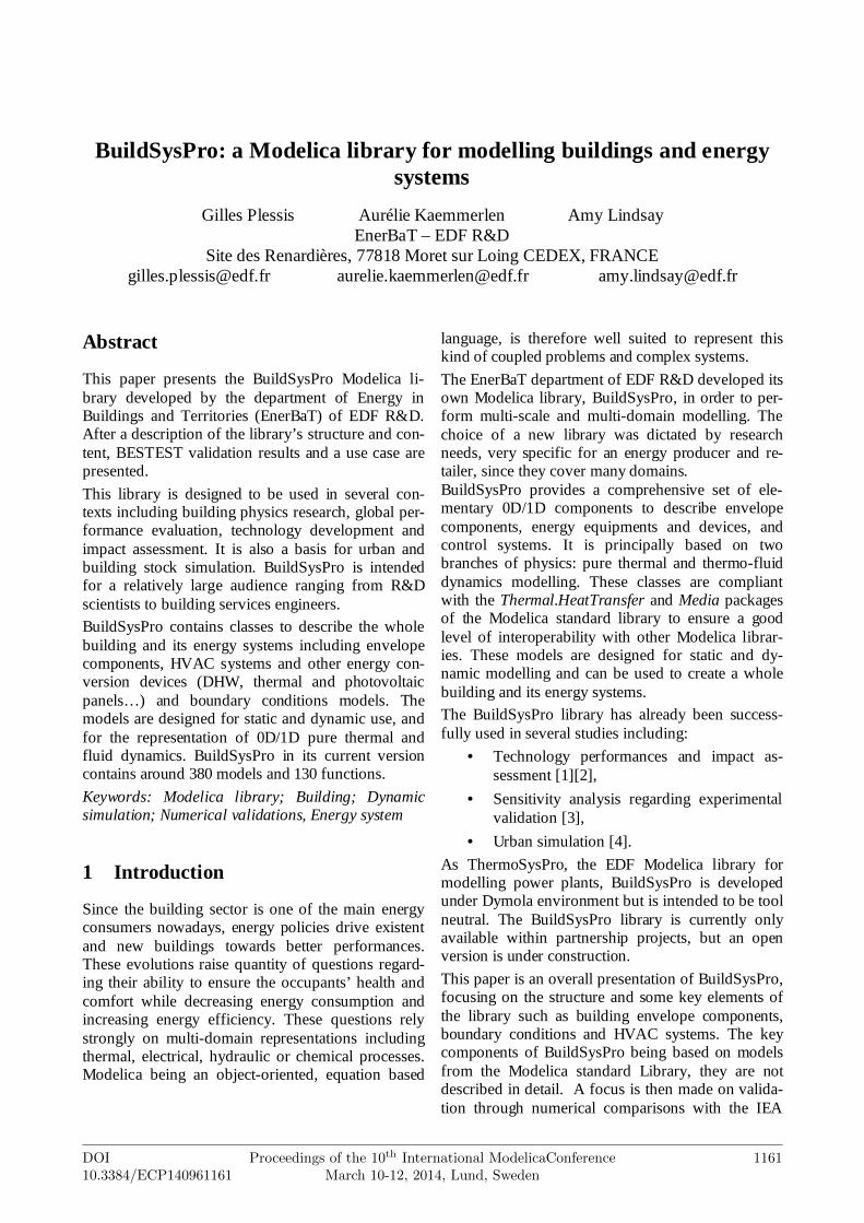
Figure 2 illustrates the structure of the BuildingEn-velope package.
BuildSysPro: a Modelica library for modelling buildings and energy systems
1162 Proceedings of the 10th International ModelicaConferenceMarch 10-12, 2014, Lund, Sweden
DOI10.3384/ECP140961161
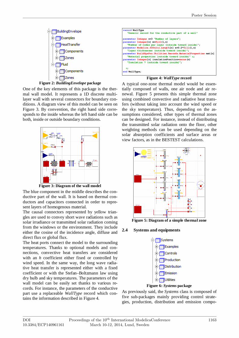
Figure 2: BuildingEnvelope package
One of the key elements of this package is the ther-mal wall model. It represents a 1D discrete multi-layer wall with several connectors for boundary con-ditions. A diagram view of this model can be seen on Figure 3. By convention, the right hand side corre-sponds to the inside whereas the left hand side can be both, inside or outside boundary conditions.
Figure 3: Diagram of the wall model
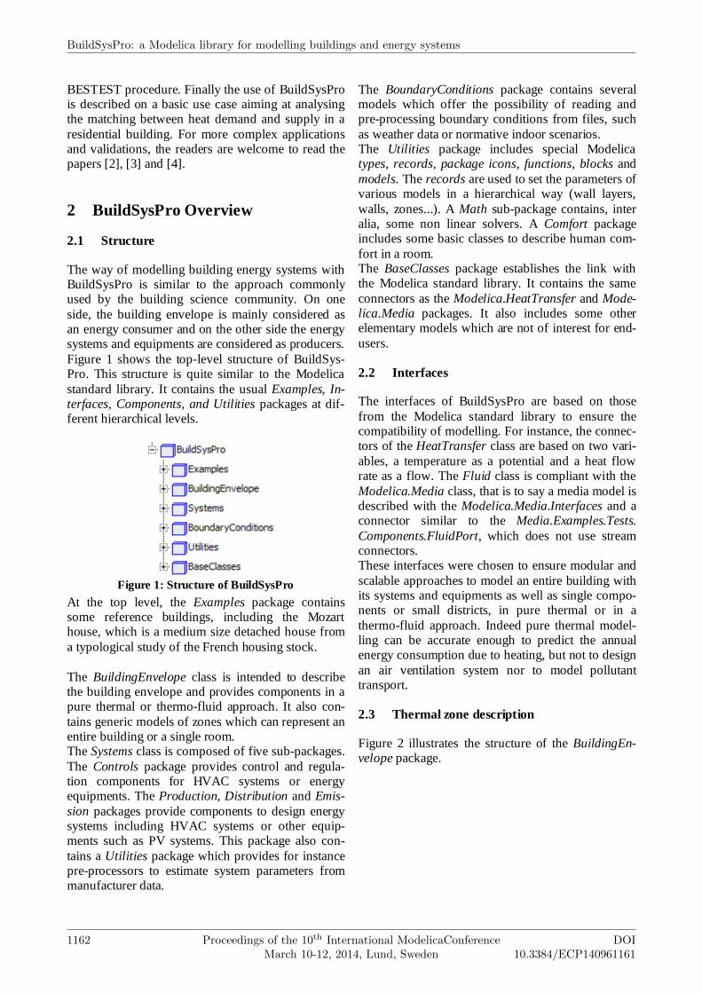
The blue component in the middle describes the con-ductive part of the wall. It is based on thermal con-ductors and capacitors connected in order to repre-sent layers of homogenous material. The causal connectors represented by yellow trian-gles are used to convey short wave radiations such as solar irradiance or transmitted solar radiation coming from the windows or the environment. They include either the cosine of the incidence angle, diffuse and direct flux or global flux. The heat ports connect the model to the surrounding temperatures. Thanks to optional models and con-nections, convective heat transfers are considered with an h coefficient either fixed or controlled by wind speed. In the same way, the long wave radia-tive heat transfer is represented either with a fixed coefficient or with the Stefan–Boltzmann law using dry bulb and sky temperatures. The parameters of the wall model can be easily set thanks to various re-cords. For instance, the parameters of the conductive part use a replaceable WallType record which con-tains the information described in Figure 4.
Figure 4: WallType record
A typical one-zone thermal model would be essen-tially composed of walls, one air node and air re-newal. Figure 5 presents this simple thermal zone using combined convective and radiative heat trans-fers (without taking into account the wind speed or the sky temperature). Thus, depending on the as-sumptions considered, other types of thermal zones can be designed. For instance, instead of distributing the transmitted solar radiation onto the floor, other weighting methods can be used depending on the solar absorption coefficients and surface areas or view factors, as in the BESTEST calculations.
Figure 5: Diagram of a simple thermal zone
2.4 Systems and equipments
Figure 6: Systems package
As previously said, the Systems class is composed of five sub-packages mainly providing control strate-gies, production, distribution and emission compo-
record WallType "Generic record for the conductive part of a wall" parameter Integer n=3 "Number of layers"; parameter Integer[n] m=fill(1,n) "Number of nodes per layer (outside toward inside)"; parameter Modelica.SIUnits.Length[n] e=0.2*fill(1,n) "Layer thicknesses (outside toward inside)"; parameter BuildSysPro.Utilities.Records.MaterialProperties mat[n] "Material properties (outside toward inside)" a; parameter Integer[n] insulationPosition=zeros(n) "Insulation ? (outside toward inside)"; a;
end WallType;
Poster Session
DOI10.3384/ECP140961161
Proceedings of the 10th International ModelicaConferenceMarch 10-12, 2014, Lund, Sweden
1163
nents. Some of these components are declined in dif-ferent modelling levels adapted to different case studies: annual, daily, hourly or even sub-hourly time steps for prototyping and precise control. For example, a simple convector can be used for studies on the electrical grid considering the 220V-50Hz power supply and the electronic regulation and components of the convector. Conversely, it can be modelled as an ideal heater or with chrono-proportional controls closer to the real dynamic be-haviour for hourly outputs and human comfort stud-ies. Another example is thermodynamic systems, such as heat pumps, modelled in BuildSysPro either with an idealised coefficient of performance, or with empiri-cal formulations depending on the boundary condi-tions (as in the use case described in paragraph 4), or with detailed modelling of the vapour compression and refrigeration cycle.
2.5 Boundary conditions
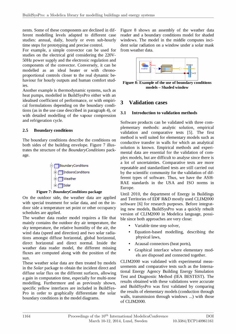
The boundary conditions describe the conditions on both sides of the building envelope. Figure 7 illus-trates the structure of the BoundaryConditions pack-age.
Figure 7: BoundaryConditions package
On the outdoor side, the weather data are applied with special treatment for solar data, and on the in-door side a temperature set point or other occupancy schedules are applied. The weather data reader model requires a file that mainly contains the outdoor dry air temperature, the sky temperature, the relative humidity of the air, the wind data (speed and direction) and two solar radia-tions amongst diffuse horizontal, global horizontal, direct horizontal and direct normal. Inside the weather data reader model, the different missing fluxes are computed along with the position of the sun. These weather solar data are then treated by models in the Solar package to obtain the incident direct and diffuse solar flux on the different surfaces, allowing a gain in computation time, especially for multi-zone modelling. Furthermore and as previously shown, specific yellow interfaces are included in BuildSys-Pro in order to graphically differentiate the solar boundary conditions in the model diagrams.
Figure 8 shows an assembly of the weather data reader and a boundary conditions model for shaded windows. The model in the middle computes inci-dent solar radiation on a window under a solar mask from weather data.
Figure 8: Example of the use of boundary conditions
models – Shaded window
3 Validation cases
3.1 Introduction to validation methods
Software products can be validated with three com-plementary methods: analytic solution, empirical validation and comparative tests [5]. The first method is well suited for elementary models such as conductive transfer in walls for which an analytical solution is known. Empirical methods and experi-mental data are essential for the validation of com-plex models, but are difficult to analyse since there is a lot of uncertainties. Comparative tests are more repeatable and standardized tests are still carried out by the scientific community for the validation of dif-ferent types of software. Thus, we have the ASH-RAE standards in the USA and ISO norms in Europe.
Until 2010, the department of Energy in Buildings and Territories of EDF R&D mostly used CLIM2000 software [6] for research purposes. Before integrat-ing new models, BuildSysPro was a quickly rebuilt version of CLIM2000 in Modelica language, possi-ble since both approaches are very close:
• Variable time step solver,
• Equation-based modelling, describing the physical laws,
• Acausal connectors (heat ports),
• Graphical interface where elementary mod-els are disposed and connected together.
CLIM2000 was validated with experimental meas-urements and comparative tests such as the Interna-tional Energy Agency Building Energy Simulation Test and Diagnostic Method (IEA BESTEST). The results obtained with these validations were accurate and BuildSysPro was first validated by comparing the results of elementary models (conduction through walls, transmission through windows ...) with those of CLIM2000.
BuildSysPro: a Modelica library for modelling buildings and energy systems
1164 Proceedings of the 10th International ModelicaConferenceMarch 10-12, 2014, Lund, Sweden
DOI10.3384/ECP140961161
As a first approach, we will focus on the comparative BESTEST validation of BuildSysPro. This procedure is adapted to validate simple building components and has been previously applied to other libraries (e.g. [10]). As such, it is a good starting point in the validation of a new library.
3.2 Comparative tests: the BESTEST qualifica-tion procedure
The BESTEST method consists in a benchmark pro-cedure for dynamic building energy simulation soft-ware established by a set of reference programs [7] [8]. This procedure was applied to validate the build-ing envelope model of BuildSysPro, as has been done with CLIM2000 or other software and more recently some Modelica libraries [9] [10]. The entire procedure is described in [8], so we will only give the key points here.
The BESTEST procedure starts with a basic building envelope controlled in temperature with only one thermal zone. The envelope is derived into two iner-tia classes: light and heavy weight. This building is located in Denver, with an extreme climate: cold clear winters and hot dry summers. The building en-velope is very sensitive to the external boundary conditions.
Small variations are made to this envelope, its con-trol strategies and its internal gains, so that it might help in identifying deficient parts of the models thanks to diagnostic flow diagrams. A program suc-cessfully passes the validation if the required outputs are positively compared with the reference pro-grams’ outputs. Table 1 summarizes the base cases (600 to 650 and 900 to 950) and the free-floating cases (600FF to 950FF) since other cases defined in BESTEST are only used for diagnostics.
Intern. gain Scenario InfiltrationType αααα int/ext εεεε int/ex t [m²] Or. Shade [W] H, C, V ACH
600 -610 1mH620 -630 1mHV640 Setback650 -, 27, V900 -910 1mH920 -930 1mHV940 Setback950 -, 27, V
600FF -, -, -650FF -, -, V900FF -, -, -950FF -, -, V
CASESOpaque surface Windows
Bas
e ca
ses
S
6 / 6 E / W
BML 0.6 0.9
BML
BMH
BMH
0.6 0.9
-
0.41
0.6 0.9 0.41
12
0.41
200
20, 27, -
200
200
20, 27, -12
6 / 6
12
S
E / W
S
-S12
12 S -
Table 1: Properties changed through the BESTEST
cases
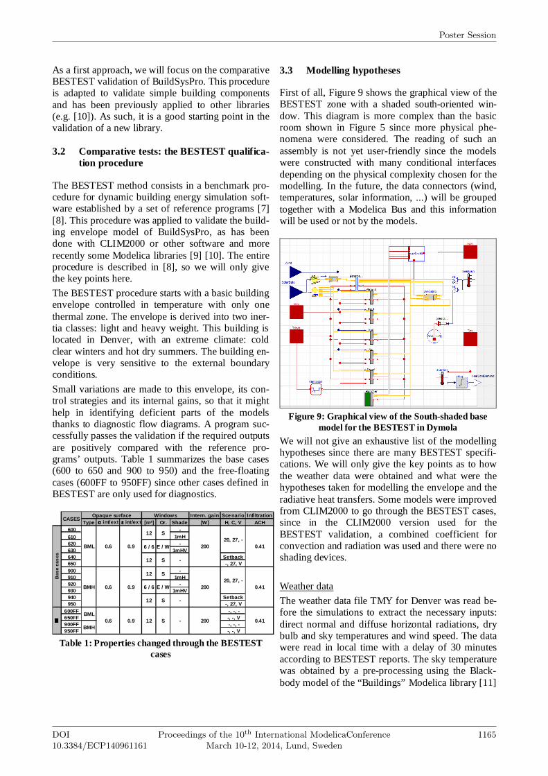
3.3 Modelling hypotheses
First of all, Figure 9 shows the graphical view of the BESTEST zone with a shaded south-oriented win-dow. This diagram is more complex than the basic room shown in Figure 5 since more physical phe-nomena were considered. The reading of such an assembly is not yet user-friendly since the models were constructed with many conditional interfaces depending on the physical complexity chosen for the modelling. In the future, the data connectors (wind, temperatures, solar information, ...) will be grouped together with a Modelica Bus and this information will be used or not by the models.
Figure 9: Graphical view of the South-shaded base
model for the BESTEST in Dymola
We will not give an exhaustive list of the modelling hypotheses since there are many BESTEST specifi-cations. We will only give the key points as to how the weather data were obtained and what were the hypotheses taken for modelling the envelope and the radiative heat transfers. Some models were improved from CLIM2000 to go through the BESTEST cases, since in the CLIM2000 version used for the BESTEST validation, a combined coefficient for convection and radiation was used and there were no shading devices.
Weather data
The weather data file TMY for Denver was read be-fore the simulations to extract the necessary inputs: direct normal and diffuse horizontal radiations, dry bulb and sky temperatures and wind speed. The data were read in local time with a delay of 30 minutes according to BESTEST reports. The sky temperature was obtained by a pre-processing using the Black-body model of the “Buildings” Modelica library [11]
Poster Session
DOI10.3384/ECP140961161
Proceedings of the 10th International ModelicaConferenceMarch 10-12, 2014, Lund, Sweden
1165
which estimates it from total opaque sky cover, dry bulb temperature and dew point temperature.
Envelope modelling
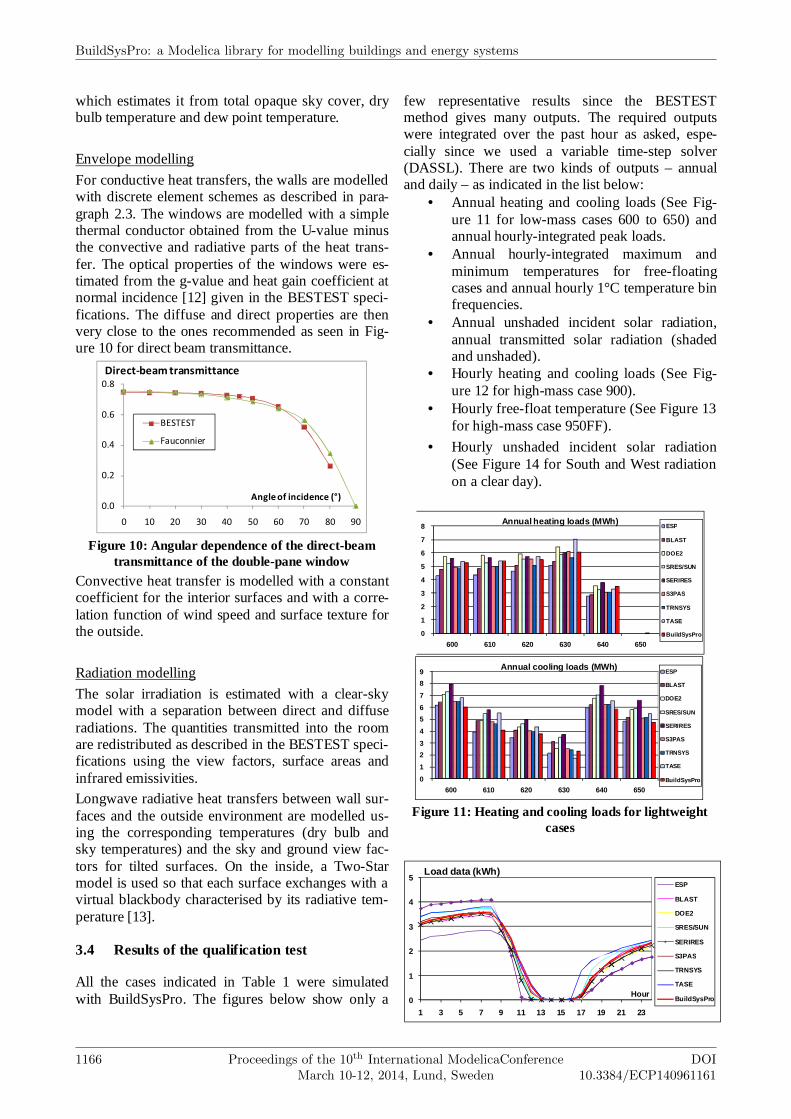
For conductive heat transfers, the walls are modelled with discrete element schemes as described in para-graph 2.3. The windows are modelled with a simple thermal conductor obtained from the U-value minus the convective and radiative parts of the heat trans-fer. The optical properties of the windows were es-timated from the g-value and heat gain coefficient at normal incidence [12] given in the BESTEST speci-fications. The diffuse and direct properties are then very close to the ones recommended as seen in Fig-ure 10 for direct beam transmittance.
0.0
0.2
0.4
0.6
0.8
0 10 20 30 40 50 60 70 80 90
Angle of incidence (°)
Direct-beam transmittance
BESTEST
Fauconnier
Figure 10: Angular dependence of the direct-beam
transmittance of the double-pane window
Convective heat transfer is modelled with a constant coefficient for the interior surfaces and with a corre-lation function of wind speed and surface texture for the outside.
Radiation modelling
The solar irradiation is estimated with a clear-sky model with a separation between direct and diffuse radiations. The quantities transmitted into the room are redistributed as described in the BESTEST speci-fications using the view factors, surface areas and infrared emissivities. Longwave radiative heat transfers between wall sur-faces and the outside environment are modelled us-ing the corresponding temperatures (dry bulb and sky temperatures) and the sky and ground view fac-tors for tilted surfaces. On the inside, a Two-Star model is used so that each surface exchanges with a virtual blackbody characterised by its radiative tem-perature [13].
3.4 Results of the qualification test
All the cases indicated in Table 1 were simulated with BuildSysPro. The figures below show only a
few representative results since the BESTEST method gives many outputs. The required outputs were integrated over the past hour as asked, espe-cially since we used a variable time-step solver (DASSL). There are two kinds of outputs – annual and daily – as indicated in the list below:
• Annual heating and cooling loads (See Fig-ure 11 for low-mass cases 600 to 650) and annual hourly-integrated peak loads.
• Annual hourly-integrated maximum and minimum temperatures for free-floating cases and annual hourly 1°C temperature bin frequencies.
• Annual unshaded incident solar radiation, annual transmitted solar radiation (shaded and unshaded).
• Hourly heating and cooling loads (See Fig-ure 12 for high-mass case 900).
• Hourly free-float temperature (See Figure 13 for high-mass case 950FF).
• Hourly unshaded incident solar radiation (See Figure 14 for South and West radiation on a clear day).
0
1
2
3
4
5
6
7
8
600 610 620 630 640 650
Annual heating loads (MWh)ESP
BLAST
DOE2
SRES/SUN
SERIRES
S3PAS
TRNSYS
TASE
BuildSysPro
0
1
2
3
4
5
6
7
8
9
600 610 620 630 640 650
Annual cooling loads (MWh)ESP
BLAST
DOE2
SRES/SUN
SERIRES
S3PAS
TRNSYS
TASE
BuildSysPro
Figure 11: Heating and cooling loads for lightweight
cases
0
1
2
3
4
5
1 3 5 7 9 11 13 15 17 19 21 23
Hour
Load data (kWh)ESP
BLAST
DOE2
SRES/SUN
SERIRES
S3PAS
TRNSYS
TASE
BuildSysPro
BuildSysPro: a Modelica library for modelling buildings and energy systems
1166 Proceedings of the 10th International ModelicaConferenceMarch 10-12, 2014, Lund, Sweden
DOI10.3384/ECP140961161
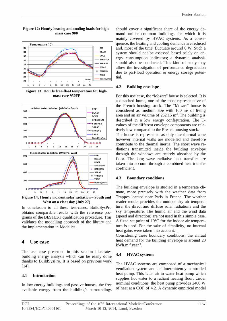
Figure 12: Hourly heating and cooling loads for high-mass case 900
20
22
24
26
28
30
32
34
36
1 3 5 7 9 11 13 15 17 19 21 23
Hour
Temperature (°C)ESP
BLAST
DOE2
SRES/SUN
SERIRES
S3PAS
TRNSYS
TASE
BuildSysPro
Figure 13: Hourly free-float temperature for high-
mass case 950FF
0
100
200
300
400
500
1 3 5 7 9 11 13 15 17 19 21 23
Incident solar radiation (Wh/m²) - South ESP
BLAST
DOE2
SRES/SUN
SERIRES
S3PAS
TRNSYS
TASE
BuildSysPro
0
200
400
600
800
1 3 5 7 9 11 13 15 17 19 21 23
Incident solar radiation (Wh/m²) - WestESP
BLAST
DOE2
SRES/SUN
SERIRES
S3PAS
TRNSYS
TASE
BuildSysPro
Figure 14: Hourly incident solar radiation – South and
West on a clear day (July 27)
In conclusion to all these test-cases, BuildSysPro obtains comparable results with the reference pro-grams of the BESTEST qualification procedure. This validates the modelling approach of the library and the implementation in Modelica.
4 Use case
The use case presented in this section illustrates building energy analysis which can be easily done thanks to BuildSysPro. It is based on previous work [14].
4.1 Introduction
In low energy buildings and passive houses, the free available energy from the building’s surroundings
should cover a significant share of the energy de-mand unlike common buildings for which it is mainly covered by HVAC systems. As a conse-quence, the heating and cooling demands are reduced and, most of the time, fluctuate around 0 W. Such a system should not be assessed based solely on en-ergy consumption indicators; a dynamic analysis should also be conducted. This kind of study may allow the investigation of performance degradation due to part-load operation or energy storage poten-tial.
4.2 Building envelope
For this use case, the “Mozart” house is selected. It is a detached home, one of the most representative of the French housing stock. The “Mozart” house is considered as medium size with 100 m² of living area and an air volume of 252.15 m3. The building is described in a low energy configuration. The U-values of the different envelope components are rela-tively low compared to the French housing stock. The house is represented as only one thermal zone however internal walls are modelled and therefore contribute to the thermal inertia. The short wave ra-diations transmitted inside the building envelope through the windows are entirely absorbed by the floor. The long wave radiative heat transfers are taken into account through a combined heat transfer coefficient.
4.3 Boundary conditions
The building envelope is studied in a temperate cli-mate, more precisely with the weather data from Trappes located near Paris in France. The weather reader model provides the outdoor dry air tempera-ture, the direct and diffuse solar radiations and the sky temperature. The humid air and the wind data (speed and direction) are not used in this simple case. A fixed set point of 19°C for the indoor air tempera-ture is used. For the sake of simplicity, no internal heat gains were taken into account. Considering these boundary conditions, the annual heat demand for the building envelope is around 20 kWh.m-2.year-1.
4.4 HVAC systems
The HVAC systems are composed of a mechanical ventilation system and an intermittently controlled heat pump. This is an air to water heat pump which supplies hot water to a radiant heating floor. Under nominal conditions, the heat pump provides 2400 W of heat at a COP of 4.2. A dynamic empirical model
Poster Session
DOI10.3384/ECP140961161
Proceedings of the 10th International ModelicaConferenceMarch 10-12, 2014, Lund, Sweden
1167
is used to represent the heat pump. It takes into ac-count the operating conditions, the part load degrada-tion and minimal operating time. The ventilation sys-tem is represented by a static model with an air change rate of 0.35 vol.h-1.
4.5 Results
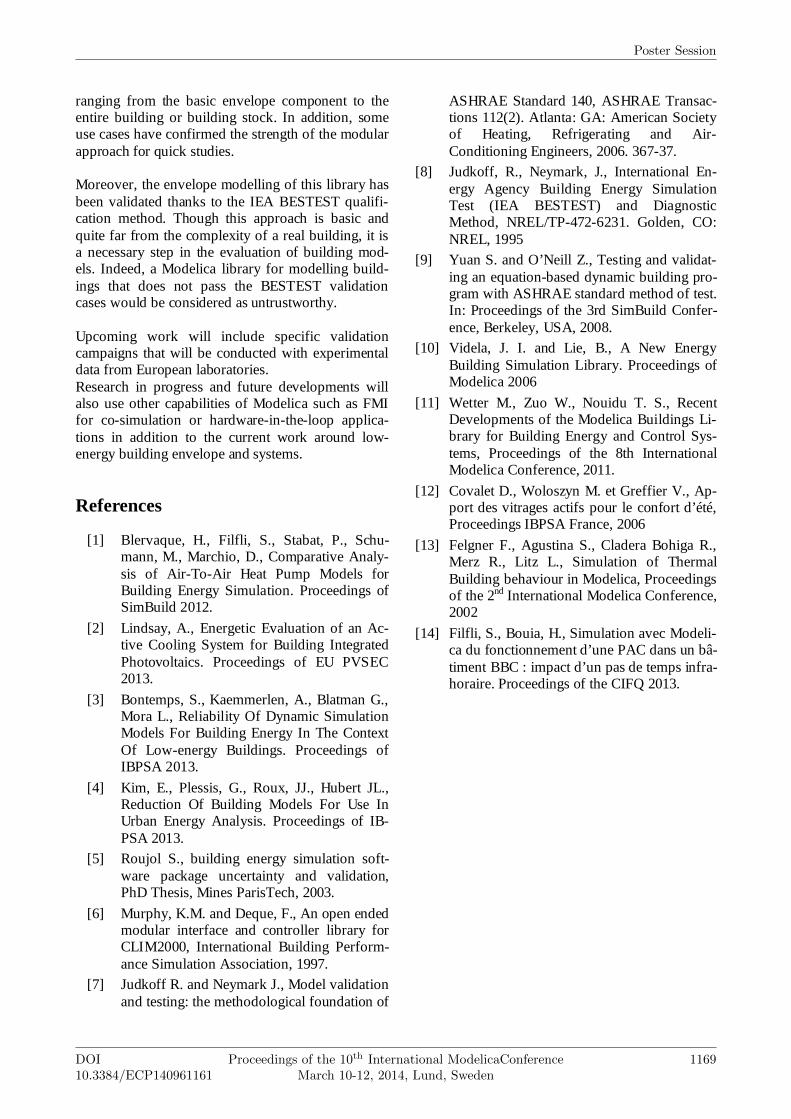
As previously mentioned this use case shows the advantage of using Modelica/Dymola and BuildSys-Pro for a simple building energy analysis. First, the energy demands can be obtained through-out the year. Figure 15 shows the relative frequen-cies of the hourly heating and cooling demands, red and blue bars respectively. This figure provides sta-tistical data about the structure of the energy demand for this specific building and these boundary condi-tions. This information is widely used for sizing ap-plications or investigating the potential of a thermal storage.
Figure 15: Relative frequencies of the hourly heating
and cooling demands [Wh]
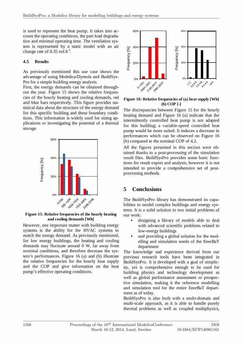
However, one important matter with building energy systems is the ability for the HVAC systems to match the energy demand. As previously mentioned, for low energy buildings, the heating and cooling demands may fluctuate around 0 W, far away from nominal conditions, and therefore decrease the sys-tem’s performances. Figure 16 (a) and (b) illustrate the relative frequencies for the hourly heat supply and the COP and give information on the heat pump’s effective operating conditions.
Figure 16: Relative frequencies of (a) heat supply [Wh] (b) COP [-]
The discrepancies between Figure 15 for the hourly heating demand and Figure 16 (a) indicate that the intermittently controlled heat pump is not adapted for this building; a variable-speed controlled heat pump would be more suited. It induces a decrease in performances which can be observed on Figure 16 (b) compared to the nominal COP of 4.2. All the figures presented in this section were ob-tained thanks to a post-processing of the simulation result files. BuildSysPro provides some basic func-tions for result export and analysis; however it is not intended to provide a comprehensive set of post- processing methods.
5 Conclusions
The BuildSysPro library has demonstrated its capa-bilities to model complex buildings and energy sys-tems. It is a solid solution to two initial problems of our work:
• designing a library of models able to deal with advanced scientific problems related to low-energy buildings
• and providing a global solution for the mod-elling and simulation needs of the EnerBaT department
The knowledge and experience derived from our previous research tools have been integrated in BuildSysPro. It is developed with a goal of simplic-ity, yet is comprehensive enough to be used for building physics and technology development as well as global performance assessment or prospec-tive simulation, making it the reference modelling and simulation tool for the entire EnerBaT depart-ment as of today. BuildSysPro is also built with a multi-domain and multi-scale approach, as it is able to handle purely thermal problems as well as coupled multiphysics,
0%
20%
40%
60%
Fre
que
ncy
[%]
0%
20%
40%
60%
Fre
que
ncy
[%]
0%
20%
40%
60%
Fre
que
ncy
[%]
BuildSysPro: a Modelica library for modelling buildings and energy systems
1168 Proceedings of the 10th International ModelicaConferenceMarch 10-12, 2014, Lund, Sweden
DOI10.3384/ECP140961161
ranging from the basic envelope component to the entire building or building stock. In addition, some use cases have confirmed the strength of the modular approach for quick studies. Moreover, the envelope modelling of this library has been validated thanks to the IEA BESTEST qualifi-cation method. Though this approach is basic and quite far from the complexity of a real building, it is a necessary step in the evaluation of building mod-els. Indeed, a Modelica library for modelling build-ings that does not pass the BESTEST validation cases would be considered as untrustworthy. Upcoming work will include specific validation campaigns that will be conducted with experimental data from European laboratories. Research in progress and future developments will also use other capabilities of Modelica such as FMI for co-simulation or hardware-in-the-loop applica-tions in addition to the current work around low-energy building envelope and systems.
References
[1] Blervaque, H., Filfli, S., Stabat, P., Schu-mann, M., Marchio, D., Comparative Analy-sis of Air-To-Air Heat Pump Models for Building Energy Simulation. Proceedings of SimBuild 2012.
[2] Lindsay, A., Energetic Evaluation of an Ac-tive Cooling System for Building Integrated Photovoltaics. Proceedings of EU PVSEC 2013.
[3] Bontemps, S., Kaemmerlen, A., Blatman G., Mora L., Reliability Of Dynamic Simulation Models For Building Energy In The Context Of Low-energy Buildings. Proceedings of IBPSA 2013.
[4] Kim, E., Plessis, G., Roux, JJ., Hubert JL., Reduction Of Building Models For Use In Urban Energy Analysis. Proceedings of IB-PSA 2013.
[5] Roujol S., building energy simulation soft-ware package uncertainty and validation, PhD Thesis, Mines ParisTech, 2003.
[6] Murphy, K.M. and Deque, F., An open ended modular interface and controller library for CLIM2000, International Building Perform-ance Simulation Association, 1997.
[7] Judkoff R. and Neymark J., Model validation and testing: the methodological foundation of
ASHRAE Standard 140, ASHRAE Transac-tions 112(2). Atlanta: GA: American Society of Heating, Refrigerating and Air-Conditioning Engineers, 2006. 367-37.
[8] Judkoff, R., Neymark, J., International En-ergy Agency Building Energy Simulation Test (IEA BESTEST) and Diagnostic Method, NREL/TP-472-6231. Golden, CO: NREL, 1995
[9] Yuan S. and O’Neill Z., Testing and validat-ing an equation-based dynamic building pro-gram with ASHRAE standard method of test. In: Proceedings of the 3rd SimBuild Confer-ence, Berkeley, USA, 2008.
[10] Videla, J. I. and Lie, B., A New Energy Building Simulation Library. Proceedings of Modelica 2006
[11] Wetter M., Zuo W., Nouidu T. S., Recent Developments of the Modelica Buildings Li-brary for Building Energy and Control Sys-tems, Proceedings of the 8th International Modelica Conference, 2011.
[12] Covalet D., Woloszyn M. et Greffier V., Ap-port des vitrages actifs pour le confort d’été, Proceedings IBPSA France, 2006
[13] Felgner F., Agustina S., Cladera Bohiga R., Merz R., Litz L., Simulation of Thermal Building behaviour in Modelica, Proceedings of the 2nd International Modelica Conference, 2002
[14] Filfli, S., Bouia, H., Simulation avec Modeli-ca du fonctionnement d’une PAC dans un bâ-timent BBC : impact d’un pas de temps infra-horaire. Proceedings of the CIFQ 2013.
Poster Session
DOI10.3384/ECP140961161
Proceedings of the 10th International ModelicaConferenceMarch 10-12, 2014, Lund, Sweden
1169