Embed Size (px)
Citation preview
Bus StopDesign Guidelines
AUGUST 2015
BUS STOP DESIGN GUIDELINES OF THE RIVERSIDE TRANSIT AGENCY
– Contents C.i –
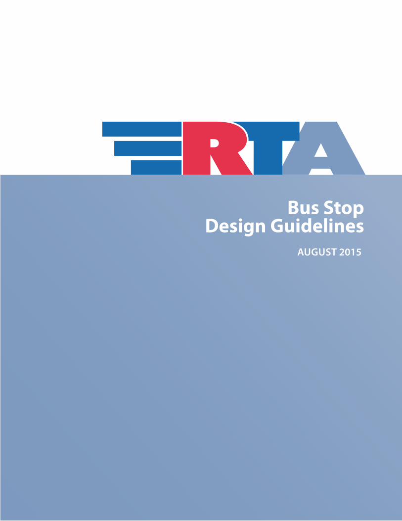
ContentsintRoDUCtion ...................................................................................................1.1
Riverside Transit Agency Mission Statement .........................................................................................1.1Riverside Transit Agency Overview .......................................................................................................1.1Purpose of Guidelines ...........................................................................................................................1.1The Mobility Challenge .........................................................................................................................1.2Transit Fueling ......................................................................................................................................1.3
DeVeLoPMent ReVieW BY RtA ...........................................................................2.1Project Data Needed to Perform the Review .........................................................................................2.1
VeHiCLe AnD stReet DesiGn stAnDARDs ..........................................................3.1RTA Fleet ..............................................................................................................................................3.1General RTA Bus Design Standards .......................................................................................................3.3Lane Design Standards .........................................................................................................................3.5
BUs stoP LoCAtion AnD PLACeMent .................................................................4.1Bus Stop Location .................................................................................................................................4.1Bus Stop Spacing ..................................................................................................................................4.2Bus Pad Minimum Specs ......................................................................................................................4.3Shelter Pad Minimum Specs/Sidewalk Width for Shelter Placement ....................................................4.3Bus Stop Configurations .......................................................................................................................4.4
tRAnsit PRioRitY teCHnoLoGies ......................................................................5.1Queue Jumps and Bypass Lanes ...........................................................................................................5.1Transit Signal Priority ...........................................................................................................................5.1Dedicated Bus Lanes .............................................................................................................................5.2
BUs stoP DesiGn ...............................................................................................6.1Identification of Bus Stops ....................................................................................................................6.1Bus Stop Amenities ..............................................................................................................................6.3Passenger Boarding Area ......................................................................................................................6.4Bus Benches .........................................................................................................................................6.5Bus Shelters ..........................................................................................................................................6.6
BUiLDinG sUstAinABLe CoMMUnities ..............................................................7.1
ConCLUsion .......................................................................................................8.1
APPenDiX A: BUs tRAnsit CoMPAtiBiLitY CHeCKList ........................................9.1
APPenDiX B: BUs DiMensions .........................................................................10.1
APPenDiX C: GLossARY oF teRMs ....................................................................11.1

BUS STOP DESIGN GUIDELINES OF THE RIVERSIDE TRANSIT AGENCY
– Contents C.ii –
FiguresFigure 1: RTA large transit bus ..............................................................................................................3.1Figure 2: RTA trolley..............................................................................................................................3.2Figure 3: RTA small transit bus ..............................................................................................................3.2Figure 4: RTA passenger van .................................................................................................................3.3Figure 5: Vehicle turning radii ...............................................................................................................3.4Figure 6: Bus stop configurations..........................................................................................................3.7Figure 7 : Bus stop configurations with bike lanes ................................................................................3.8Figure 8: Far-side stops .........................................................................................................................4.1Figure 9: Near-side stops ......................................................................................................................4.1Figure 10: Mid-block stops ...................................................................................................................4.2Figure 11: Specifications for concrete bus pads ....................................................................................4.3Figure 12: Example shelter pad specification ........................................................................................4.4Figure 13: Curbside stop configurations for one bus .............................................................................4.5Figure 14: Curbside stop configurations for two buses ..........................................................................4.6Figure 15: Bus bulb configurations .......................................................................................................4.7Figure 16: Bus turnout configurations ..................................................................................................4.8Figure 17: Bus stop sign parameters .....................................................................................................6.1Figure 18: Bus stop with passenger amenities ......................................................................................6.4Figure 19: Typical bus bench design .....................................................................................................6.5Figure 20: Bus shelter ...........................................................................................................................6.6Figure 21: Real-time information at corona transit center ....................................................................6.7Figure 22: Kiosk with ATIS module ........................................................................................................6.8Figure 23: Example of bus bay layouts at a transit center .....................................................................6.9Figure 24: Corona transit center ..........................................................................................................6.10Figure 25: Example solar powered light ..............................................................................................6.11Figure 26: Solar-powered bus stop light. ............................................................................................6.11
TablesTable 1: Vehicle design standards .........................................................................................................3.3Table 2: Bus stop spacing ......................................................................................................................4.3Table 3: Bus stop amenities warrant chart ............................................................................................6.3Table 4: Transit planning resources .......................................................................................................8.1Table 5: Bus transit compatibility checklist ...........................................................................................9.1Table 6: Dimensions for standard transit bus ......................................................................................10.1Table 7: Dimensions for trolley bus .....................................................................................................10.2Table 8: Dimensions for small bus and paratransit van .......................................................................10.3Table 9: Vehicles in paratransit fleet ...................................................................................................10.3
BUS STOP DESIGN GUIDELINES OF THE RIVERSIDE TRANSIT AGENCY
– intRoDUC tion 1.1 –
Introduction
Riverside Transit Agency Mission StatementThe Riverside Transit Agency (RTA), western Riverside County’s multi-modal transportation provider, shall provide for a variety of transportation needs in a cost-effective and efficient manner, for all the residents of member communities. The Agency is committed to providing safe, reliable, courteous, accessible, and user-friendly transit services to our customers.
Riverside Transit Agency OverviewWith a region spanning 2,500 square miles, RTA maintains one of the largest bus transit service areas in the nation. As the service area continues to grow in both population and employment, RTA is challenged with establishing and/or adjusting routes and services to suit the region’s changing needs.
The service area is located in the heart of Inland Southern California, about 60 miles east of downtown Los Angeles. Formed under a Joint Powers Agreement (JPA) in 1975, RTA is the authorized Consolidated Transportation Service Agency (CTSA) for western Riverside County. RTA is governed by a Board of Directors comprised of 22 elected officials from 18 cities and 4 Riverside County Supervisors.
Purpose of GuidelinesThe purpose of this document is to educate local planners, developers, and decision-makers about transit’s needs and offer clear and uniform guidance for the design and placement of bus-related facilities and amenities.1 These guidelines are intended to identify transit-specific design considerations applying only to trip-generating locations and projects. RTA advises that the final design and placement of transit amenities should be conducted concurrently with ongoing street
1. These design guidelines are intended to provide accurate, authoritative direction for general situations. They are not in-tended to provide site-specific, detailed public transit, engineering, architectural, construction, legal, or other information. The reader will need to adjust the information contained in the guidelines to site-specific needs, constraints, and to all ap-plicable laws, regulations, and codes. Further, if the reader desires expert advice concerning any of the technical references contained in these guidelines, the reader is encouraged to retain the services of appropriate experts. Thes guidelines are provided with the understanding that RTA is not engaged in the rendering of any professional service.
BUS STOP DESIGN GUIDELINES OF THE RIVERSIDE TRANSIT AGENCY
– intRoDUC tion 1.2 –
improvements or within proposed residential or commercial developments in a timely fashion that is compatible with these guidelines and the local jurisdiction’s design standards and planning process or calendar.
The guidance for providing and designing transit facilities and amenities is based on the following framework:
■ Adherence to industry-standard bus operations and safety requirements
■ Relevance to current engineering practices in western Riverside County
■ Compatibility with standards used by other transit operators in the western United States
■ Provision of amenities necessary for maintaining and growing transit ridership
■ Identification of anticipated mobility benefits to developers and local agencies in providing transit service for future residents, tenants, and customers
■ Compatibility of transit amenities with other roadway uses
The Mobility ChallengeAs population and vehicle miles traveled increase during this era of explosive growth in the region, alternative transportation, such as public transit, is being challenged with meeting a growing portion of mobility needs. Because bus fares make up less than 20 percent of the operating expenses, they alone cannot pay for an effective network of routes. Therefore, RTA relies on additional funding support from local, state, and federal programs and grants.
RTA constantly monitors the bus system in light of variability in customer demands, financial resources, and changing development patterns in its service area. The Agency strives to serve the most people in the most efficient and effective manner. These factors are coalescing around an emerging level of unprecedented demand on our transportation systems.
To make transit more attractive and accessible in the days ahead, especially to new riders who choose transit over a personal vehicle, the RTA planning staff works with local governments to encourage provision of transit amenities and community infrastructure that make finding, waiting for and boarding a bus a safe, accessible, convenient and pleasant experience.
BUS STOP DESIGN GUIDELINES OF THE RIVERSIDE TRANSIT AGENCY
– intRoDUC tion 1.3 –
Transit amenities may include:
■ Bus turnouts or bulbs instead of a curb stop
■ Accessible and convenient pathways from commercial buildings or institutions to the bus stop
■ Shorter routes from residential developments to the bus stop
■ Bus benches, shelters, signage and other passenger information
■ Good multi-modal connectivity, i.e. bike-to-bus and bus-to-train conveniences at designated transit nodes
Implementing transit amenities plays an important part in meeting the overall mobility challenge. Amenities improve the overall consumer experience and encourage the use of public transit. Because these features are more subtle than scheduling or routing, they are often overlooked in transit plans. Through successful communication with local governments, RTA can encourage the implementation of more and improved amenities. These guidelines provide a framework for successful interagency partnerships and cooperation.
Transit FuelingIn response to air quality concerns and government regulation, the industry has been transitioning to alternative fuels. As a result of the 1999 RTA Board policy, all large buses directly operated by RTA now use clean Compressed Natural Gas (CNG). Some mid-sized buses continue to operate on unleaded gasoline while a more reliable CNG engine design is tested. Smaller vehicles continue to operate on unleaded gasoline.
Clean fuels allow buses to be temporarily housed or parked in areas that would have caused health, cleanliness, or odor annoyances in the past. More than ever, the clean-fuel bus is now considered a good neighbor.
BUS STOP DESIGN GUIDELINES OF THE RIVERSIDE TRANSIT AGENCY
– DeVeLoPMent ReVieW BY RtA 2.1 –
Development Review by RTA
Project Data Needed to Perform the ReviewAlthough the process of locating and designing bus stops and other transit amenities may appear fairly simple to the casual observer, optimal design requires the consideration and consolidation of many factors. The ideal arrangement of bus stops seeks a balance between the needs of all roadway and bus users, as well as property owners.
The key to effective integration of the local planning process with long-range transit service goals is keeping RTA informed of upcoming projects in the local community. The easiest method is to simply include RTA on your Planning or Public Works Department standard mailing list for new project submittals. First, all local jurisdictions are urged to notify RTA of their planning review calendar or cycles, such as the dates, times and places of regular pre-submittal conferences, development review committees, planning commissions and city council meetings, plus special community outreach meetings or similar notices that could have an effect on transit. RTA encourages local planning or public works departments to orient staff, when possible, to become knowledgeable of transit interests. A liaison or staff contact with RTA for development review purposes would be ideal.
What Types of Local Projects does RTA Need to Review?
Residential, Commercial and Industrial Tentative Tracts or Parcel Maps: Using these, RTA can best recommend locations for bus stops, bus turnouts and review in detail the pedestrian access and circulation patterns of the project before the development process has progressed too far.
Commercial Centers – Regional Malls to Local Shopping Centers: Because these projects are usually trip generators for clients and employees at potential community centers, activity or employment nodes and are placed on major arterial streets, it is highly likely transit routes and bus stops will be involved. Larger projects may warrant a transit center.
Industrial Projects – Business or Office Parks: These are also employment centers that can generate considerable transit use.
Institutional Uses – Schools, Public Buildings, Hospitals, etc.: Also employment centers, these kinds of projects tend to attract transit users and may require special treatment to promote pedestrian access and pathways between bus stops and building entrances.
BUS STOP DESIGN GUIDELINES OF THE RIVERSIDE TRANSIT AGENCY
– DeVeLoPMent ReVieW BY RtA 2.2 –
Plot Plans or Site Plans: These plans allow RTA to review smaller but possibly significant projects at important intersections. Smaller projects located off arterials probably would not be reviewed.
Conditional Use Permits: Since these planning actions cover a great variety of significant projects, RTA recommends that at least the accompanying site plan be sent to the Agency for review.
Street Improvement Plans (primarily for arterial streets): These projects often impact existing and proposed bus stops. RTA recommends that upgraded streets and arterials include general upgrades of transit facilities as well. This includes replacement of any bus stops that are impacted by street construction.
Notices of Preparation, Draft Environmental Impact Reports: Although many of the above types of projects may require these documents, RTA prefers to review projects at this point, providing transit’s input at the earliest possible stage.
General Plans: To ensure the land use, circulation, and community design elements are generally supportive of transit routes and transit centers, and their connectivity to all modes of mobility.
Specific Plans: To employ the best practices in locating potential transit centers and bus routes that provide the greatest opportunity for the public to have the option of using transit.
Rule of Thumb: If in Doubt, Send It Out
What to Include?First, RTA will generally accept what the local jurisdiction normally includes in its mail-outs or internet postings. Although some of the following listings may seem redundant, it will serve as a checklist for the RTA package.
Kinds of Specific Documents RTA Needs for its Review
■ Site plan, tract map or conceptual is needed for most projects
■ Project transmittal or project announcement notice, giving basic project information and the action’s status in the planning process
■ Project description such as location, type of use and number of residential units, or amount of square feet in a commercial project
■ Hardscape, landscape, walking and/or parking plans indicating circulation patterns (ingress and egress) through the project
■ Revised or modified plans to any of the above
■ Periodic lists of the department’s recently approved (over a two-year span) and upcoming projects

BUS STOP DESIGN GUIDELINES OF THE RIVERSIDE TRANSIT AGENCY
– DeVeLoPMent ReVieW BY RtA 2.3 –
What Is NOT NeededRTA normally does not require grading plans, building elevations, interior building plans, sign plans, structural or mechanical plans, elevation drawings or similar. Small-size photocopies of the development plans, rather than full-size blueprints or plots are usually acceptable as long as the writing is legible. RTA strives to use only the usual mail-out format and materials employed by the local jurisdiction.
Typical Small Projects NOT ReviewedEven if a mail-out is received by the Agency, RTA will not review certain small projects unless they could have a direct bearing on existing or proposed transit. If these are sent to RTA, they may be determined to be non-issues after a preliminary screening.
Such projects would include:
■ Tract maps or parcel maps of one to five lots
■ Lot splits or lot line adjustments, or second-unit residences
■ Most zone changes
■ Minor conditional use permits or minor development review
■ Variances
■ Non-conforming use determinations
■ Changes in use or ownership in a tenant space of a shopping center or office complex, including tenant improvements
■ Utility relocation plans and cell phone towers
■ Extensions of time for planning cases
Where to Mail Documents?Planning Department Riverside Transit Agency PO Box 59968 Riverside, CA 92517-1968

BUS STOP DESIGN GUIDELINES OF THE RIVERSIDE TRANSIT AGENCY
– DeVeLoPMent ReVieW BY RtA 2.4 –
Turn-Around Time for Adequate Review and CommentRTA advises that review packages be sent out to allow approximately two to three weeks from the day of RTA’s receipt of materials to the day reviewed results are sent back to local planners. However, this ideal can be impeded by the following time constraints:
■ Incomplete submittal to RTA (not enough information)
■ Time needed for mail to move through the delivery system
■ RTA or local agency staff work load or holidays
■ Complexity of the project
■ Duration of the planning process cycle used by the local jurisdiction
RTA’s review should be returned to the local agency prior to key dates such as when staff reports are due, the close of EIR comment periods, or planning commission meetings.
RTA’s Recommendations to Overseeing AgenciesRTA can only advise and recommend project modifications that would benefit the transit user. There are very few state or federal laws governing transit amenities or pedestrian circulation, especially on local streets or private property.
RTA’s progress in establishing its standards is reliant on the good will and cooperative spirit of local jurisdictions working towards the common goal of improved mobility and less congestion and air pollution in the region. For example, economies can be achieved by joint development that includes a transit component. There are up to four phases of the RTA development review process once all pertinent documents are received from the local jurisdiction or its consultants.
1. Internal Staff Review: A transit planner analyzes the project with respect to transit operations and may forward a technical report to the director of planning for approval. The internal review reports on the project’s likely impacts on existing or future transit routes and discusses possible alternatives. The basic results of the staff review are either “no impacts to transit” or “there are transit amenity, pedestrian access or other operational improvements or suggestions.”
2. Agency Letter: Whatever the internal staff recommendation, a formal letter is prepared that transforms the internal staff review into either an approval document or a set of recommendations for the local jurisdiction or private developer to consider. Because RTA has no enforcement power, the letter will speak of advisory recommendations rather than requirements for project modifications that are in the best interests of public mobility. Additionally, RTA staff will often suggest language for conditions of approval that may be inserted into the final project materials.
3. Local Boards of Review: In some cases, RTA will make a presentation before local development review committees, planning commissions and city councils.
BUS STOP DESIGN GUIDELINES OF THE RIVERSIDE TRANSIT AGENCY
– DeVeLoPMent ReVieW BY RtA 2.5 –
4. Implementation: As projects move to the construction stage, RTA staff, local agencies and the developer may confer regarding practical adjustments to the approved plans.
During the development review process, RTA staff may occasionally make a field visit or confer in person or by phone with local staff or project proponents to gather all pertinent facts or explain RTA’s recommendation. These meetings can identify issues and solutions at the earliest possible date, to the benefit of all parties involved.
How to Appeal an RTA Staff RecommendationDevelopers, lead agencies, local government staff and other interested parties are invited to contact RTA staff if there are questions about an RTA recommendation. The Agency welcomes alternative approaches and always strives toward a win/win outcome when working with developers, builders, and local jurisdictions.
Additionally, any developer, or public agency may speak at any public meeting or official hearing appropriate to the RTA-related matter in question. For example, if RTA has recommended that the site plan for a new senior apartment complex include a bus stop in front of its recreation building, the developer might offer an alternative location for the stop that is acceptable to RTA. Transit amenity requests are suitable topics for public discussion and modification through local planning commissions, city councils or board of supervisors.
BUS STOP DESIGN GUIDELINES OF THE RIVERSIDE TRANSIT AGENCY
– VeHiCLe AnD stReet DesiGn stAnDARDs 3.1 –
Vehicle and Street Design StandardsWhen designing roadways, intersections, bus stops, and other transit facilities, it is important to consider the characteristics of the transit vehicles that will be using them. Designing local infrastructure to accommodate transit vehicles will ensure safe and efficient maneuverability and enhanced passenger safety, convenience and comfort. Incorporating design standards for transit vehicles in the planning process prevents unplanned construction expenses from factors such as road pavement damage. Finally, designing around transit supports a “Complete Streets” approach to roadway use.
While RTA uses certain vehicle types for certain purposes, it is important that all roadways and bus stops be designed around the parameters for the largest vehicle size that will use the location, now and in the future. This provides RTA with flexibility in how it operates its fleet and the opportunity to expand vehicle size on any given route. This is especially important for bus routes that may grow in ridership and move some or all trips to directly operate full sized transit buses in place of contracted smaller buses. It is also important for future Bus Rapid Transit (BRT) corridors where articulated buses may eventually be deployed.
RTA FleetRTA operates five types of vehicles for different mobility purposes.
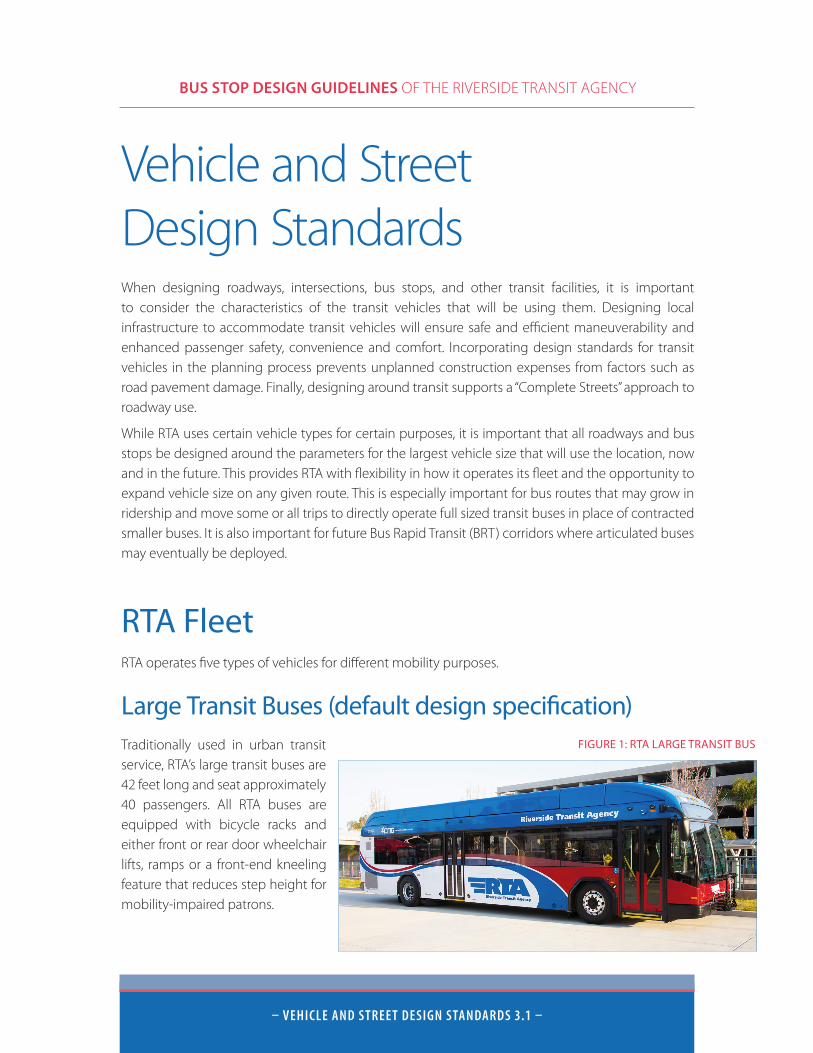
Large Transit Buses (default design specification)Traditionally used in urban transit service, RTA’s large transit buses are 42 feet long and seat approximately 40 passengers. All RTA buses are equipped with bicycle racks and either front or rear door wheelchair lifts, ramps or a front-end kneeling feature that reduces step height for mobility-impaired patrons.
FIGURE 1: RTA LARGE TRANSIT BUS
BUS STOP DESIGN GUIDELINES OF THE RIVERSIDE TRANSIT AGENCY
– VeHiCLe AnD stReet DesiGn stAnDARDs 3.2 –
Medium Transit BusesTraditionally used in suburban transit service, RTA’s medium transit buses seat approximately 30 passengers. RTA uses medium buses on many local and commuter services, including CommuterLink routes. These buses are also accessible to persons with disabilities. CommuterLink buses offer additional amenities such as Wi-Fi, more comfortable seating, cup holders, fold-down tables, and 12V power connections for hookup of laptop computers and other approved equipment.
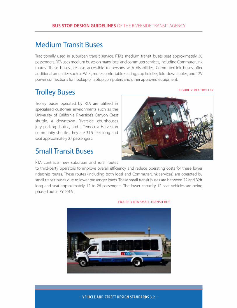
Trolley BusesTrolley buses operated by RTA are utilized in specialized customer environments such as the University of California Riverside’s Canyon Crest shuttle, a downtown Riverside courthouses jury parking shuttle, and a Temecula Harveston community shuttle. They are 31.5 feet long and seat approximately 27 passengers.
Small Transit BusesRTA contracts new suburban and rural routes to third-party operators to improve overall efficiency and reduce operating costs for these lower ridership routes. These routes (including both local and CommuterLink services) are operated by small transit buses due to lower passenger loads. These small transit buses are between 22 and 32ft long and seat approximately 12 to 26 passengers. The lower capacity 12 seat vehicles are being phased out in FY 2016.
FIGURE 2: RTA TROLLEY
FIGURE 3: RTA SMALL TRANSIT BUS
BUS STOP DESIGN GUIDELINES OF THE RIVERSIDE TRANSIT AGENCY
– VeHiCLe AnD stReet DesiGn stAnDARDs 3.3 –
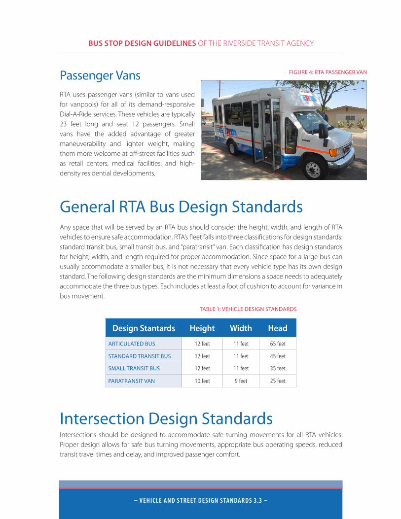
Passenger VansRTA uses passenger vans (similar to vans used for vanpools) for all of its demand-responsive Dial-A-Ride services. These vehicles are typically 23 feet long and seat 12 passengers. Small vans have the added advantage of greater maneuverability and lighter weight, making them more welcome at off-street facilities such as retail centers, medical facilities, and high-density residential developments.
General RTA Bus Design StandardsAny space that will be served by an RTA bus should consider the height, width, and length of RTA vehicles to ensure safe accommodation. RTA’s fleet falls into three classifications for design standards: standard transit bus, small transit bus, and “paratransit” van. Each classification has design standards for height, width, and length required for proper accommodation. Since space for a large bus can usually accommodate a smaller bus, it is not necessary that every vehicle type has its own design standard. The following design standards are the minimum dimensions a space needs to adequately accommodate the three bus types. Each includes at least a foot of cushion to account for variance in bus movement.
Intersection Design StandardsIntersections should be designed to accommodate safe turning movements for all RTA vehicles. Proper design allows for safe bus turning movements, appropriate bus operating speeds, reduced transit travel times and delay, and improved passenger comfort.
FIGURE 4: RTA PASSENGER VAN
Design Stantards Height Width Head
ARTICULATED BUS 12 feet 11 feet 65 feet
STANDARD TRANSIT BUS 12 feet 11 feet 45 feet
SMALL TRANSIT BUS 12 feet 11 feet 35 feet
PARATRANSIT VAN 10 feet 9 feet 25 feet
TABLE 1: VEHICLE DESIGN STANDARDS
BUS STOP DESIGN GUIDELINES OF THE RIVERSIDE TRANSIT AGENCY
– VeHiCLe AnD stReet DesiGn stAnDARDs 3.4 –
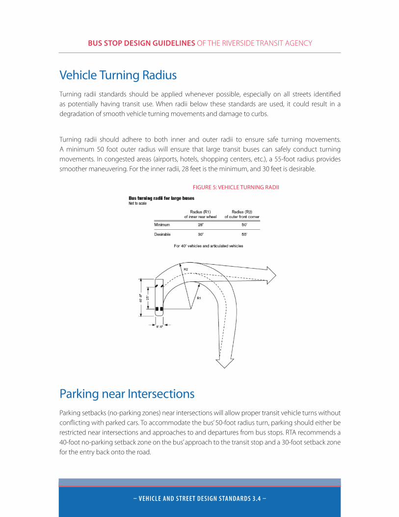
Vehicle Turning RadiusTurning radii standards should be applied whenever possible, especially on all streets identified as potentially having transit use. When radii below these standards are used, it could result in a degradation of smooth vehicle turning movements and damage to curbs.
Turning radii should adhere to both inner and outer radii to ensure safe turning movements. A minimum 50 foot outer radius will ensure that large transit buses can safely conduct turning movements. In congested areas (airports, hotels, shopping centers, etc.), a 55-foot radius provides smoother maneuvering. For the inner radii, 28 feet is the minimum, and 30 feet is desirable.
Parking near IntersectionsParking setbacks (no-parking zones) near intersections will allow proper transit vehicle turns without conflicting with parked cars. To accommodate the bus’ 50-foot radius turn, parking should either be restricted near intersections and approaches to and departures from bus stops. RTA recommends a 40-foot no-parking setback zone on the bus’ approach to the transit stop and a 30-foot setback zone for the entry back onto the road.
FIGURE 5: VEHICLE TURNING RADII
BUS STOP DESIGN GUIDELINES OF THE RIVERSIDE TRANSIT AGENCY
– VeHiCLe AnD stReet DesiGn stAnDARDs 3.5 –
Lane Design StandardsBus travel lanes should also be designed to ensure the safety of both the passenger on-board and the surrounding vehicles, bicycles, and pedestrians.
Lane WidthFor both public and private roadways that accommodate larger transit vehicles, RTA recommends a 12-foot lane width for the curb lane to ensure proper maneuverability of the larger buses. This width provides adequate maneuvering space.
Bus Lane ClearanceRTA buses usually travel in the curbside traffic lane and make frequent stops to pick up and drop off passengers. Therefore it is important to keep these areas clear of potential obstructions.
Overhead obstructions such as trees, signs, and utility wiring should not enter into the bus profile area, i.e. less than 12 feet above the street surface.
Street-side obstructions should not be located within two feet of the edge of the street to avoid being struck by a bus mirror when the vehicle travels by or is parked close to the curb or pavement edge. This lateral clearance is important at both ground level and at the top of the bus.
Bus stop placement must be in an area with good line of sight visibility, and clear of storm drains, obstructions, and tripping hazards.
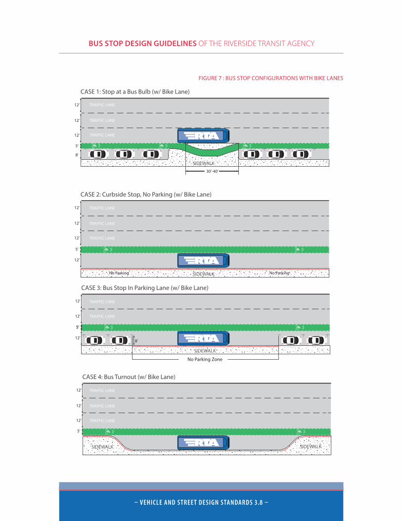
Figure 6 and Figure 7 show eight different examples of bus stop integration with traffic lanes, parking lanes, and bike lanes.
BUS STOP DESIGN GUIDELINES OF THE RIVERSIDE TRANSIT AGENCY
– VeHiCLe AnD stReet DesiGn stAnDARDs 3.6 –
Roadway Design StandardsMany factors contribute to roadway design including the aforementioned bus dimensions and turning radii, anticipated vehicle speeds, traffic volume, and on-street parking conditions. These guidelines define specific standards for lane widths, grades, and roadway pavement.
Road SurfacesRoadway pavements need to be of sufficient strength to accommodate repetitive bus axle loads of up to 25,000 lbs. Concrete is preferred to avoid failure problems that are experienced with asphalt, especially where buses start, stop, or turn. Concrete aids in the retention of roadway surface shape, drainage capabilities, and skid resistance.
For bus stop areas, including bus turnouts and terminals, concrete is strongly recommended. Due to the load and sheer force applied to pavement surfaces during bus starting and stopping movements, concrete has the best potential for shape retention.
Road GradesThe maximum slope or grade that a standard 40-foot transit bus can negotiate safely and economically is usually 6 to 12 percent. In an uphill direction, the maximum sustained grade for roadways designed for bus service should not exceed six percent. For the downhill direction, the roadway should be designed with a maximum 12 percent grade.
In some cases where the roadway is especially steep, such as Summerhill Drive in Lake Elsinore or Reche Vista Drive in Moreno Valley, a climbing lane for buses and trucks is advised. In addition, abrupt changes in grade should be avoided due to bus overhangs and ground clearance requirements.
Breakover angles (bus tilting due to dips or bumps in the street) need to be minimized or the underbody of buses will be damaged.

BUS STOP DESIGN GUIDELINES OF THE RIVERSIDE TRANSIT AGENCY
– VeHiCLe AnD stReet DesiGn stAnDARDs 3.7 –
CASE 1: Stop at a Bus Bulb
SIDEWALK8’
12’
12’
12’ TRAFFIC LANE
TRAFFIC LANE
TRAFFIC LANE
30’-40’
CASE 1: Stop at a Bus Bulb (w/ Bike Lane)
12’
12’
12’
SIDEWALK
8’
5’
TRAFFIC LANE
TRAFFIC LANE
TRAFFIC LANE
30’-40’
TRAFFIC LANE
TRAFFIC LANE
TRAFFIC LANE
CASE 2: Curbside Stop, No Parking
SIDEWALK
12’
12’
12’
No ParkingNo Parking
TRAFFIC LANE
TRAFFIC LANE
TRAFFIC LANE
5’
CASE 2: Curbside Stop, No Parking (w/ Bike Lane)
SIDEWALK
12’
12’
12’
12’
No ParkingNo Parking
TRAFFIC LANE
TRAFFIC LANE
CASE 3: Bus Stop In Parking Lane
8’
SIDEWALK
No Parking Zone
12’
12’
12’
50’ 40’ Min.60’ Des.
40’ Min.60’ Des.
TRAFFIC LANE
TRAFFIC LANE
CASE 3: Bus Stop In Parking Lane (w/ Bike Lane)
No Parking Zone
SIDEWALK
8’
12’
12’
12’
5’
TRAFFIC LANE
TRAFFIC LANE
TRAFFIC LANE
CASE 4: Bus Turnout
SIDEWALKSIDEWALK
12’
12’
12’
50’ 40’ Min.60’ Des.
40’ Min.60’ Des.
TRAFFIC LANE
TRAFFIC LANE
TRAFFIC LANE
5’
5’
CASE 4: Bus Turnout (w/ Bike Lane)
SIDEWALKSIDEWALK
12’
12’
12’
FIGURE 6: BUS STOP CONFIGURATIONS
BUS STOP DESIGN GUIDELINES OF THE RIVERSIDE TRANSIT AGENCY
– VeHiCLe AnD stReet DesiGn stAnDARDs 3.8 –
CASE 1: Stop at a Bus Bulb
SIDEWALK8’
12’
12’
12’ TRAFFIC LANE
TRAFFIC LANE
TRAFFIC LANE
30’-40’
CASE 1: Stop at a Bus Bulb (w/ Bike Lane)
12’
12’
12’
SIDEWALK
8’
5’
TRAFFIC LANE
TRAFFIC LANE
TRAFFIC LANE
30’-40’
TRAFFIC LANE
TRAFFIC LANE
TRAFFIC LANE
CASE 2: Curbside Stop, No Parking
SIDEWALK
12’
12’
12’
No ParkingNo Parking
TRAFFIC LANE
TRAFFIC LANE
TRAFFIC LANE
5’
CASE 2: Curbside Stop, No Parking (w/ Bike Lane)
SIDEWALK
12’
12’
12’
12’
No ParkingNo Parking
TRAFFIC LANE
TRAFFIC LANE
CASE 3: Bus Stop In Parking Lane
8’
SIDEWALK
No Parking Zone
12’
12’
12’
50’ 40’ Min.60’ Des.
40’ Min.60’ Des.
TRAFFIC LANE
TRAFFIC LANE
CASE 3: Bus Stop In Parking Lane (w/ Bike Lane)
No Parking Zone
SIDEWALK
8’
12’
12’
12’
5’
TRAFFIC LANE
TRAFFIC LANE
TRAFFIC LANE
CASE 4: Bus Turnout
SIDEWALKSIDEWALK
12’
12’
12’
50’ 40’ Min.60’ Des.
40’ Min.60’ Des.
TRAFFIC LANE
TRAFFIC LANE
TRAFFIC LANE
5’
5’
CASE 4: Bus Turnout (w/ Bike Lane)
SIDEWALKSIDEWALK
12’
12’
12’
FIGURE 7 : BUS STOP CONFIGURATIONS WITH BIKE LANES
BUS STOP DESIGN GUIDELINES OF THE RIVERSIDE TRANSIT AGENCY
– BUs stoP LoC Ation AnD PLACeMent 4.1 –
Bus Stop Location and Placement
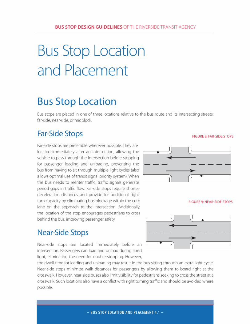
Bus Stop LocationBus stops are placed in one of three locations relative to the bus route and its intersecting streets: far-side, near-side, or midblock.
Far-Side StopsFar-side stops are preferable wherever possible. They are located immediately after an intersection, allowing the vehicle to pass through the intersection before stopping for passenger loading and unloading, preventing the bus from having to sit through multiple light cycles (also allows optimal use of transit signal priority system). When the bus needs to reenter traffic, traffic signals generate period gaps in traffic flow. Far-side stops require shorter deceleration distances and provide for additional right turn capacity by eliminating bus blockage within the curb lane on the approach to the intersection. Additionally, the location of the stop encourages pedestrians to cross behind the bus, improving passenger safety.
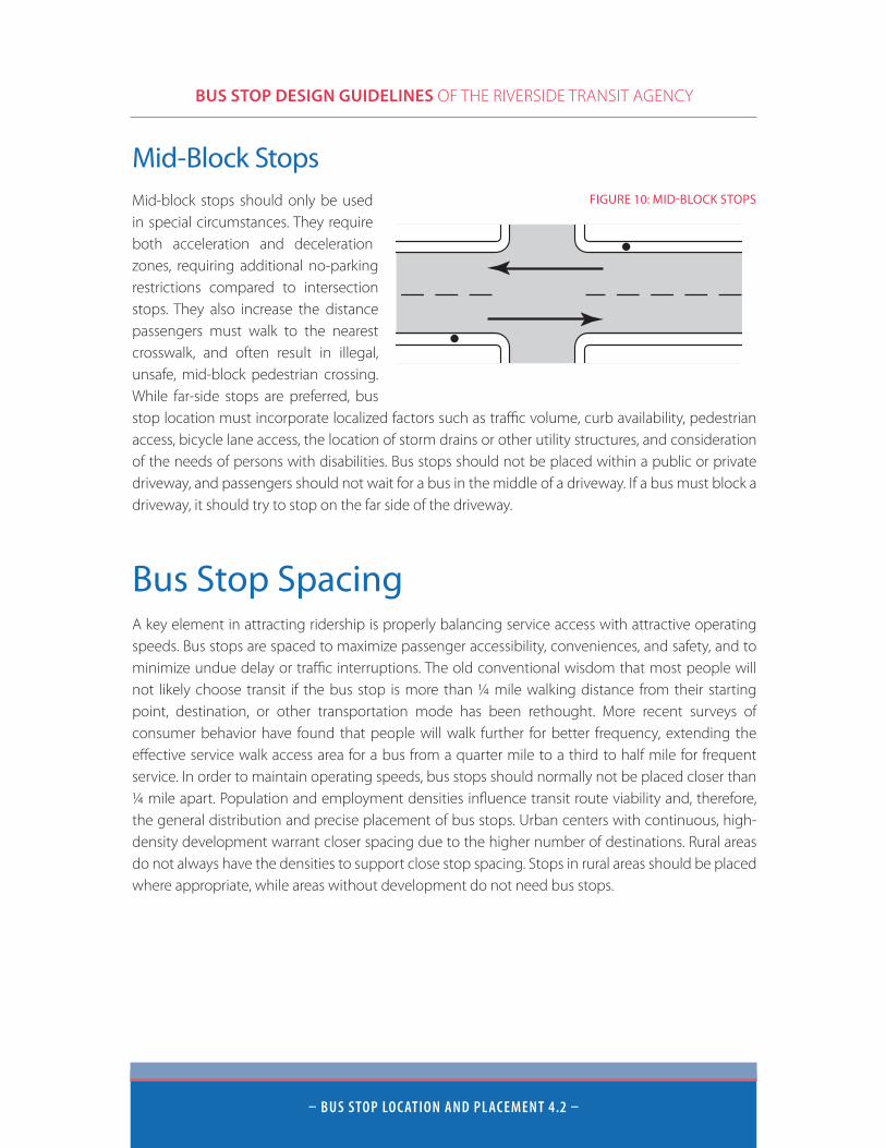
Near-Side StopsNear-side stops are located immediately before an intersection. Passengers can load and unload during a red light, eliminating the need for double-stopping. However, the dwell time for loading and unloading may result in the bus sitting through an extra light cycle. Near-side stops minimize walk distances for passengers by allowing them to board right at the crosswalk. However, near-side buses also limit visibility for pedestrians seeking to cross the street at a crosswalk. Such locations also have a conflict with right turning traffic and should be avoided where possible.
NEAR-SIDE STOP
FAR-SIDE STOP
MID-BLOCK STOP
FIGURE 8: FAR-SIDE STOPS
NEAR-SIDE STOP
FAR-SIDE STOP
MID-BLOCK STOP
FIGURE 9: NEAR-SIDE STOPS
BUS STOP DESIGN GUIDELINES OF THE RIVERSIDE TRANSIT AGENCY
– BUs stoP LoC Ation AnD PLACeMent 4.2 –
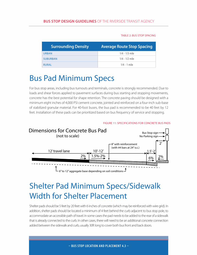
Mid-Block StopsMid-block stops should only be used in special circumstances. They require both acceleration and deceleration zones, requiring additional no-parking restrictions compared to intersection stops. They also increase the distance passengers must walk to the nearest crosswalk, and often result in illegal, unsafe, mid-block pedestrian crossing. While far-side stops are preferred, bus stop location must incorporate localized factors such as traffic volume, curb availability, pedestrian access, bicycle lane access, the location of storm drains or other utility structures, and consideration of the needs of persons with disabilities. Bus stops should not be placed within a public or private driveway, and passengers should not wait for a bus in the middle of a driveway. If a bus must block a driveway, it should try to stop on the far side of the driveway.
Bus Stop SpacingA key element in attracting ridership is properly balancing service access with attractive operating speeds. Bus stops are spaced to maximize passenger accessibility, conveniences, and safety, and to minimize undue delay or traffic interruptions. The old conventional wisdom that most people will not likely choose transit if the bus stop is more than ¼ mile walking distance from their starting point, destination, or other transportation mode has been rethought. More recent surveys of consumer behavior have found that people will walk further for better frequency, extending the effective service walk access area for a bus from a quarter mile to a third to half mile for frequent service. In order to maintain operating speeds, bus stops should normally not be placed closer than ¼ mile apart. Population and employment densities influence transit route viability and, therefore, the general distribution and precise placement of bus stops. Urban centers with continuous, high-density development warrant closer spacing due to the higher number of destinations. Rural areas do not always have the densities to support close stop spacing. Stops in rural areas should be placed where appropriate, while areas without development do not need bus stops.
NEAR-SIDE STOP
FAR-SIDE STOP
MID-BLOCK STOP
FIGURE 10: MID-BLOCK STOPS
BUS STOP DESIGN GUIDELINES OF THE RIVERSIDE TRANSIT AGENCY
– BUs stoP LoC Ation AnD PLACeMent 4.3 –
Bus Pad Minimum Specs For bus stop areas, including bus turnouts and terminals, concrete is strongly recommended. Due to loads and shear forces applied to pavement surfaces during bus starting and stopping movements, concrete has the best potential for shape retention. The concrete paving should be designed with a minimum eight inches of 4,000 PSI cement concrete, jointed and reinforced on a four-inch sub-base of stabilized granular material. For 40-foot buses, the bus pad is recommended to be 40 feet by 12 feet. Installation of these pads can be prioritized based on bus frequency of service and stopping.
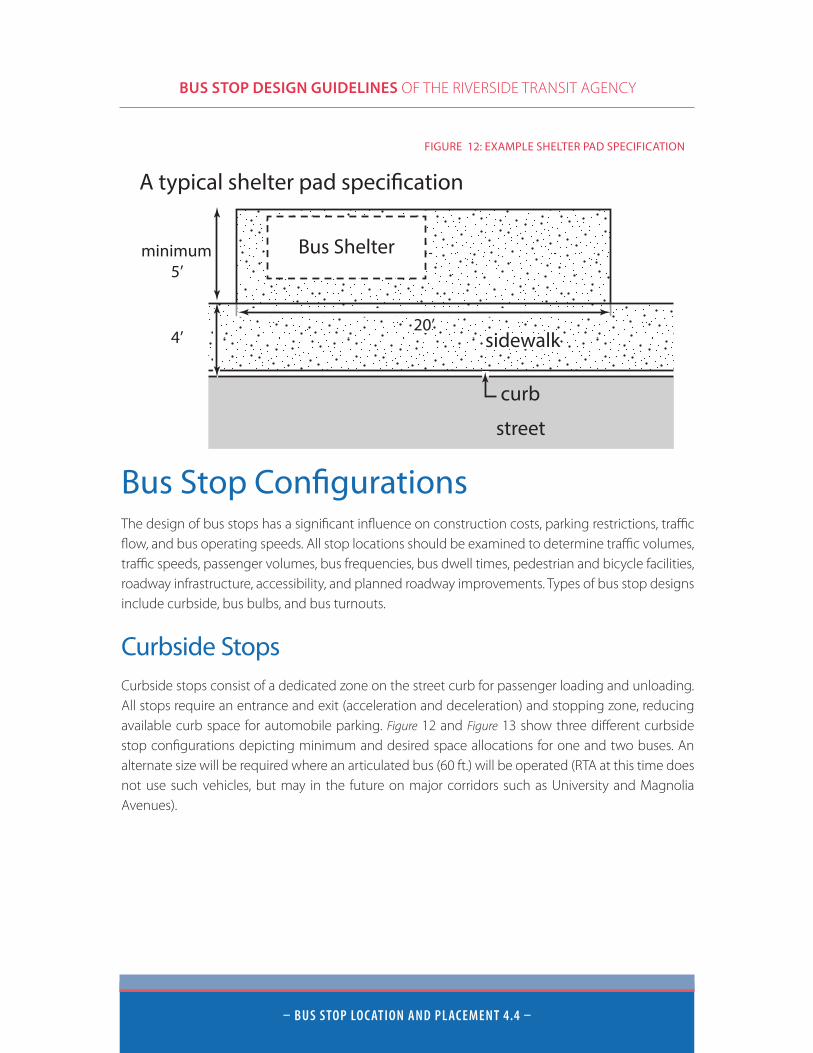
Shelter Pad Minimum Specs/Sidewalk Width for Shelter PlacementShelter pads should be 5 feet by 20 feet with 6 inches of concrete (which may be reinforced with wire grid). In addition, shelter pads should be located a minimum of 4 feet behind the curb adjacent to bus stop pole, to accommodate an accessible path of travel. In some cases the pad needs to be added to the rear of a sidewalk that is already connected to the curb. In other cases, there will need to be an additional concrete connection added between the sidewalk and curb, usually 30ft long to cover both bus front and back doors.
Surrounding Density Average Route Stop SpacingURBAN 1/4 - 1/3 mile
SUBURBAN 1/4 - 1/2 mile
RURAL 1/4 - 1 mile
TABLE 2: BUS STOP SPACING
Dimensions for Concrete Bus Pad(not to scale)
10’-12’12’ travel lane 1.5’-2’
2’
2% 1.5%-2% 6%
6” to 12” aggregate base depending on soil conditions
2%
8” with reinforcement(with #4 bars at 24” o.c.)
Bus Stop signNo Parking sign
FIGURE 11: SPECIFICATIONS FOR CONCRETE BUS PADS
BUS STOP DESIGN GUIDELINES OF THE RIVERSIDE TRANSIT AGENCY
– BUs stoP LoC Ation AnD PLACeMent 4.4 –
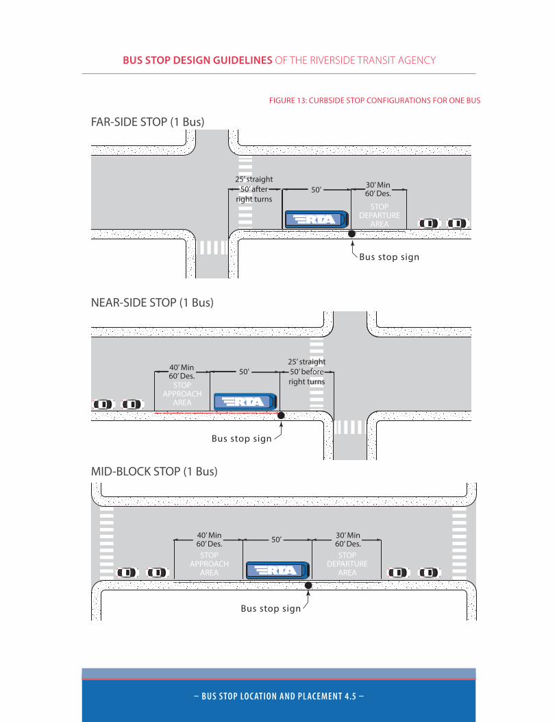
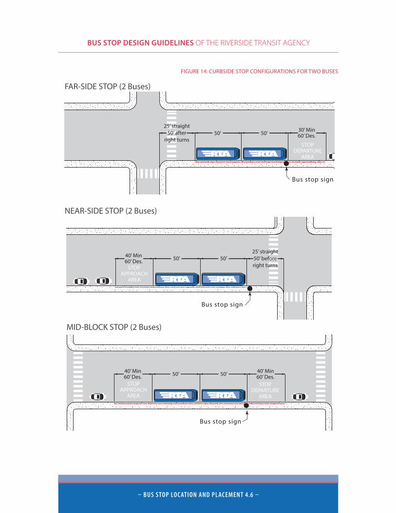
Bus Stop ConfigurationsThe design of bus stops has a significant influence on construction costs, parking restrictions, traffic flow, and bus operating speeds. All stop locations should be examined to determine traffic volumes, traffic speeds, passenger volumes, bus frequencies, bus dwell times, pedestrian and bicycle facilities, roadway infrastructure, accessibility, and planned roadway improvements. Types of bus stop designs include curbside, bus bulbs, and bus turnouts.
Curbside StopsCurbside stops consist of a dedicated zone on the street curb for passenger loading and unloading. All stops require an entrance and exit (acceleration and deceleration) and stopping zone, reducing available curb space for automobile parking. Figure 12 and Figure 13 show three different curbside stop configurations depicting minimum and desired space allocations for one and two buses. An alternate size will be required where an articulated bus (60 ft.) will be operated (RTA at this time does not use such vehicles, but may in the future on major corridors such as University and Magnolia Avenues).
street
Bus Shelter
4’
minimum5’
curb
A typical shelter pad speci�cation
sidewalk20’
FIGURE 12: EXAMPLE SHELTER PAD SPECIFICATION
BUS STOP DESIGN GUIDELINES OF THE RIVERSIDE TRANSIT AGENCY
– BUs stoP LoC Ation AnD PLACeMent 4.5 –
50’40’ Min60’ Des.
30’ Min60’ Des.
Bus stop sign
MID-BLOCK STOP (1 Bus)
STOPAPPROACH
AREA
STOPDEPARTURE
AREA
50’ 50’40’ Min60’ Des.
40’ Min60’ Des.
Bus stop sign
MID-BLOCK STOP (2 Buses)
STOPAPPROACH
AREA
STOPDEPARTURE
AREA
STOPAPPROACH
AREA
50’ 50’40’ Min60’ Des.
Bus stop sign
NEAR-SIDE STOP (2 Buses)
25’ straight50’ beforeright turnsSTOP
APPROACHAREA
50’40’ Min60’ Des.
Bus stop sign
NEAR-SIDE STOP (1 Bus)
25’ straight50’ beforeright turns
STOPDEPARTURE
AREA
Bus stop sign
50’ 30’ Min60’ Des.
FAR-SIDE STOP (1 Bus)
25’ straight50’ after
right turnsSTOP
DEPARTUREAREA
Bus stop sign
50’ 50’
FAR-SIDE STOP (2 Buses)
30’ Min60’ Des.
25’ straight50’ after
right turns
FIGURE 13: CURBSIDE STOP CONFIGURATIONS FOR ONE BUS
BUS STOP DESIGN GUIDELINES OF THE RIVERSIDE TRANSIT AGENCY
– BUs stoP LoC Ation AnD PLACeMent 4.6 –
50’40’ Min60’ Des.
30’ Min60’ Des.
Bus stop sign
MID-BLOCK STOP (1 Bus)
STOPAPPROACH
AREA
STOPDEPARTURE
AREA
50’ 50’40’ Min60’ Des.
40’ Min60’ Des.
Bus stop sign
MID-BLOCK STOP (2 Buses)
STOPAPPROACH
AREA
STOPDEPARTURE
AREA
STOPAPPROACH
AREA
50’ 50’40’ Min60’ Des.
Bus stop sign
NEAR-SIDE STOP (2 Buses)
25’ straight50’ beforeright turnsSTOP
APPROACHAREA
50’40’ Min60’ Des.
Bus stop sign
NEAR-SIDE STOP (1 Bus)
25’ straight50’ beforeright turns
STOPDEPARTURE
AREA
Bus stop sign
50’ 30’ Min60’ Des.
FAR-SIDE STOP (1 Bus)
25’ straight50’ after
right turnsSTOP
DEPARTUREAREA
Bus stop sign
50’ 50’
FAR-SIDE STOP (2 Buses)
30’ Min60’ Des.
25’ straight50’ after
right turns
FIGURE 14: CURBSIDE STOP CONFIGURATIONS FOR TWO BUSES

BUS STOP DESIGN GUIDELINES OF THE RIVERSIDE TRANSIT AGENCY
– BUs stoP LoC Ation AnD PLACeMent 4.7 –
Bus BulbsBus bulbs have an extended sidewalk up to the travel lane, allowing the bus to remain in the rightmost travel lane when picking up and dropping off passengers. The bulb typically replaces a small section of on-street parking to allow passengers to safely reach the bus. Bus bulbs eliminate the need for an entrance and exit zone, and the need to merge back into traffic, providing additional space for parked cars and minimal travel time delay. The bus bulb area provides additional waiting space for patrons, allowing for stop amenities and wheelchair access while removing passengers from pedestrian flow on the sidewalk. Bus bulbs provide the opportunity for bikes to pass to the right of a bus without compromising bicyclist safety. However, bus bulbs do block automobile traffic in the travel lane which can result in unsafe passing maneuvers. Bus bulbs are higher cost infrastructure compared to simple curbside stops. The bus bulb option can be considered at locations or on corridors where RTA may partner with a local jurisdiction for funding in order to provide a traffic-calmed and improved parking environment. The bus will gain from not having any delay when restarting after stopping but may lose time waiting for cars reverse parking. The bus bulbs are not recommended for highly congested streets but ideally are for calming relatively moderate traffic flow streets where vehicle speeds may be a concern.
BUS BULB w/ BIKE LANE
30’-40’
Sidewalk8’
5’
12’
BUS BULB
8’
12’
Sidewalk
30’-40’
FIGURE 15: BUS BULB CONFIGURATIONS
BUS STOP DESIGN GUIDELINES OF THE RIVERSIDE TRANSIT AGENCY
– BUs stoP LoC Ation AnD PLACeMent 4.8 –
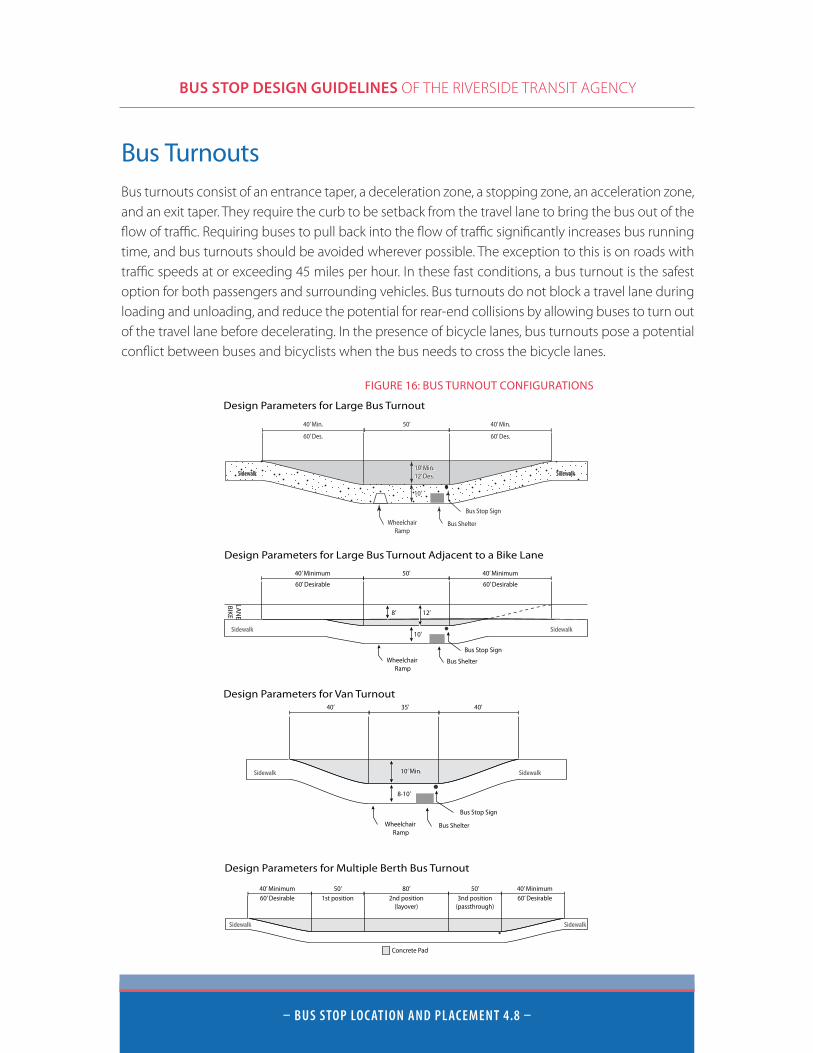
Bus TurnoutsBus turnouts consist of an entrance taper, a deceleration zone, a stopping zone, an acceleration zone, and an exit taper. They require the curb to be setback from the travel lane to bring the bus out of the flow of traffic. Requiring buses to pull back into the flow of traffic significantly increases bus running time, and bus turnouts should be avoided wherever possible. The exception to this is on roads with traffic speeds at or exceeding 45 miles per hour. In these fast conditions, a bus turnout is the safest option for both passengers and surrounding vehicles. Bus turnouts do not block a travel lane during loading and unloading, and reduce the potential for rear-end collisions by allowing buses to turn out of the travel lane before decelerating. In the presence of bicycle lanes, bus turnouts pose a potential conflict between buses and bicyclists when the bus needs to cross the bicycle lanes.
FIGURE 16: BUS TURNOUT CONFIGURATIONS
Sidewalk Sidewalk
Wheelchair Ramp
Bus Shelter
Bus Stop Sign
40’ Minimum
60’ Desirable
50’ 40’ Minimum
60’ Desirable
10’
LAN
EBIKE 8’ 12’
Design Parameters for Large Bus Turnout Adjacent to a Bike Lane
Sidewalk Sidewalk
Wheelchair Ramp
Bus Shelter
Bus Stop Sign
10’ Min.
8-10’
40’ 35’ 40’
Design Parameters for Van Turnout
Sidewalk Sidewalk
40’ Minimum60’ Desirable
50’ 40’ Minimum60’ Desirable
Design Parameters for Multiple Berth Bus Turnout
80’ 50’
Concrete Pad
1st position 2nd position(layover)
3nd position(passthrough)
Design Parameters for Large Bus Turnout
SidewalkSidewalk
Bus Stop SignBus Stop Sign
SidewalkSidewalk
10’
10’ Min.12’ Des.
50’ 40’ Min.40’ Min.
60’ Des.60’ Des.
Bus ShelterBus ShelterWheelchairRamp
BUS STOP DESIGN GUIDELINES OF THE RIVERSIDE TRANSIT AGENCY
– tRAnsit PRioRit Y teCHnoLoGies 5.1 –
Transit Priority Technologies
Queue Jumps and Bypass LanesQueue jumps and bypass lanes are a form of Transit Signal Priority in which buses are allowed to use restricted lanes to bypass queued vehicles at signalized intersections, reducing travel time and providing improved service reliability.
A queue jump allows a bus to enter into a short lane (that could also be used as a right turn lane) that is located adjacent to the through lane, stopping at the near side of the intersection. A separate signal would provide an early green light to the bus to move through the intersection and into the through travel lane prior to general traffic. Near-side bus stops are typically used with queue jump lanes.
A bypass lane, which would be adjacent to the through lane, would not have a separate signal, but would continue through the intersection with general traffic into a receiving lane on the opposite side of the intersection prior to entering into the through lane. Far-side stops are typically used with bypass lanes.
These facilities would typically only be justified at high bus movement volumes (multiple buses per cycle at peak times) which are also impeding traffic in general.
Transit Signal PriorityDelays from signalized intersections typically account for 10 to 20 percent of all bus delays. Transit Signal Priority can be implemented at intersections with traffic signals to reduce transit delay and improve service reliability. Transit Signal Priority refers to a variety of real-time strategies designed to provide priority for a transit vehicle approaching an intersection.
With signal priority, a bus approaching an intersection requests priority, and normal signal operation is modified to provide preferential treatment for this oncoming bus. Common types of priority include green extension (extending the green time to allow the approaching bus to continue without stopping), early green (shortening the preceding phases to minimize red time for the approaching bus), phase insertion (inserting a special priority phase into the normal signal sequence), and phase rotation (modifying the order of signal phases). Priority is usually only provided to late running buses in existing industry applications but should be considered as a tool for use at all times (excluding facilitating early departures from terminals and time points) to reduce transit travel times (with schedules updated to capture any consistently achieved time savings).
BUS STOP DESIGN GUIDELINES OF THE RIVERSIDE TRANSIT AGENCY
– tRAnsit PRioRit Y teCHnoLoGies 5.2 –
Dedicated Bus LanesDedicated bus lanes create “Bus Only” lanes on major streets to allow for higher bus speeds and greater reliability. Dedicated bus lanes are typically applied on major routes with frequent headways (10 minutes or better at peak) or where traffic congestion may significantly affect reliability. Bus lanes help raise the visibility, speed, and reliability (real and perceived) of transit services which attracts new riders. Prohibiting right turns from the dedicated bus lane keeps the lane clear and reduces potential conflict with other vehicles. These lanes should be a minimum of 12 feet wide.
BUS STOP DESIGN GUIDELINES OF THE RIVERSIDE TRANSIT AGENCY
– BUs stoP DesiGn 6.1 –
Bus Stop Design
Identification of Bus Stops
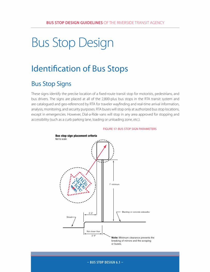
Bus Stop SignsThese signs identify the precise location of a fixed-route transit stop for motorists, pedestrians, and bus drivers. The signs are placed at all of the 2,800-plus bus stops in the RTA transit system and are catalogued and geo-referenced by RTA for traveler wayfinding and real-time arrival information, analysis, monitoring, and security purposes. RTA buses will stop only at authorized bus stop locations, except in emergencies. However, Dial-a-Ride vans will stop in any area approved for stopping and accessibility (such as a curb parking lane, loading or unloading zone, etc.).
Note: Minimum clearance prevents thebreaking of mirrors and the scrapingor buses.
Bus stop sign placement criteriaNot to scale
7' minimum
2'-0"
2'-9"
Blacktop or concrete sidewalks
Not closer than
Street
FIGURE 17: BUS STOP SIGN PARAMETERS
BUS STOP DESIGN GUIDELINES OF THE RIVERSIDE TRANSIT AGENCY
– BUs stoP DesiGn 6.2 –
There are several sign installation criteria that contribute to passenger and public safety, convenience, visibility, and comfort:
■ The bottom of the sign must be seven feet above the sidewalk and its top must be no higher than ten feet.
■ The sign post must be at least two feet, nine inches in from the curb face or road edge.
■ The outside edge of the sign must be no less than two feet from the curb or road edge.
■ Trees, buildings, and other structures should not obstruct the bus stop signs from view by oncoming buses and intending passengers.
■ Signs should be placed as a guide for passengers and operators as to where the front of the bus should stop.
■ Signs are usually mounted on square steel or aluminum posts. This consistency is particularly useful for visually-impaired riders to locate, by means of touch, the exact location of the bus stop.
■ Check for existing utility lines (gas, water, etc.) prior to sign placement.
■ Signs should be visible from either direction.
■ Bus stop signs are placed independently and unattached to other street signs to clearly emphasize transit stop identity.
Sign ContentSign size and content can vary as transit marketing programs continue to improve the sign’s graphic message. At a minimum, the sign confirms the location of a bus stop, identifies RTA routes stopping there, and displays the transit information telephone number. Additional informational signage boards or kiosks, and stop identification numbers are often attached to the signpost, as well as bus schedule and or route map displays. All sign content should be ADA-approved as to font and point size of lettering. Consistency across the network for RTA identity is critical, so any branding change must be promptly applied network-wide (within one service change or four months).
Painted Curbs and SidewalksRTA will normally paint existing curbs in red color to identify the curbside area reserved for bus stop use. White lettering of “BUS STOP” is often stenciled onto the red-painted curb, especially in high-traffic areas.
The exact location on the sidewalk where the bus doors will open should also be clearly marked by the bus stop sign post. Having the bus stop at a precise location each time will reduce passenger walk times/distances and provide consistency for passengers in knowing where the bus will stop.
BUS STOP DESIGN GUIDELINES OF THE RIVERSIDE TRANSIT AGENCY
– BUs stoP DesiGn 6.3 –
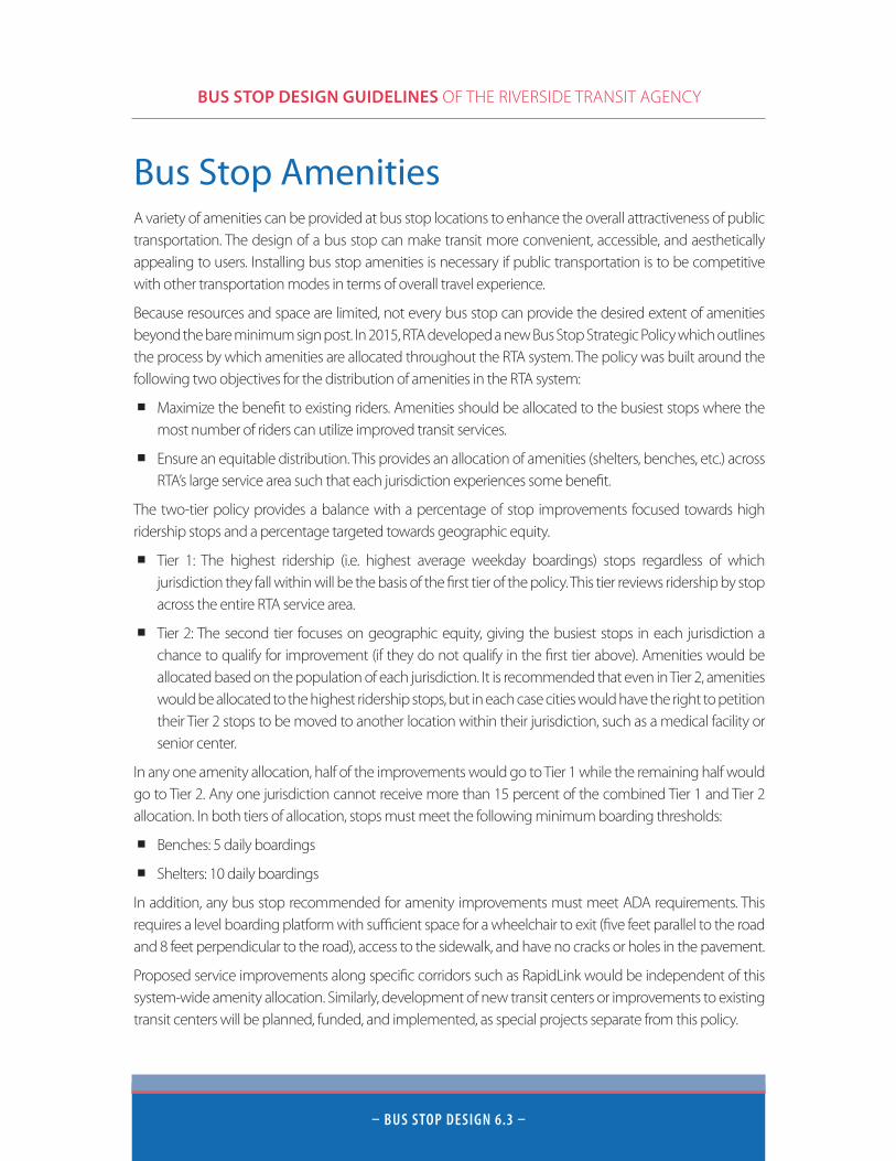
Bus Stop AmenitiesA variety of amenities can be provided at bus stop locations to enhance the overall attractiveness of public transportation. The design of a bus stop can make transit more convenient, accessible, and aesthetically appealing to users. Installing bus stop amenities is necessary if public transportation is to be competitive with other transportation modes in terms of overall travel experience.
Because resources and space are limited, not every bus stop can provide the desired extent of amenities beyond the bare minimum sign post. In 2015, RTA developed a new Bus Stop Strategic Policy which outlines the process by which amenities are allocated throughout the RTA system. The policy was built around the following two objectives for the distribution of amenities in the RTA system:
■ Maximize the benefit to existing riders. Amenities should be allocated to the busiest stops where the most number of riders can utilize improved transit services.
■ Ensure an equitable distribution. This provides an allocation of amenities (shelters, benches, etc.) across RTA’s large service area such that each jurisdiction experiences some benefit.
The two-tier policy provides a balance with a percentage of stop improvements focused towards high ridership stops and a percentage targeted towards geographic equity.
■ Tier 1: The highest ridership (i.e. highest average weekday boardings) stops regardless of which jurisdiction they fall within will be the basis of the first tier of the policy. This tier reviews ridership by stop across the entire RTA service area.
■ Tier 2: The second tier focuses on geographic equity, giving the busiest stops in each jurisdiction a chance to qualify for improvement (if they do not qualify in the first tier above). Amenities would be allocated based on the population of each jurisdiction. It is recommended that even in Tier 2, amenities would be allocated to the highest ridership stops, but in each case cities would have the right to petition their Tier 2 stops to be moved to another location within their jurisdiction, such as a medical facility or senior center.
In any one amenity allocation, half of the improvements would go to Tier 1 while the remaining half would go to Tier 2. Any one jurisdiction cannot receive more than 15 percent of the combined Tier 1 and Tier 2 allocation. In both tiers of allocation, stops must meet the following minimum boarding thresholds:
■ Benches: 5 daily boardings
■ Shelters: 10 daily boardings
In addition, any bus stop recommended for amenity improvements must meet ADA requirements. This requires a level boarding platform with sufficient space for a wheelchair to exit (five feet parallel to the road and 8 feet perpendicular to the road), access to the sidewalk, and have no cracks or holes in the pavement.
Proposed service improvements along specific corridors such as RapidLink would be independent of this system-wide amenity allocation. Similarly, development of new transit centers or improvements to existing transit centers will be planned, funded, and implemented, as special projects separate from this policy.

BUS STOP DESIGN GUIDELINES OF THE RIVERSIDE TRANSIT AGENCY
– BUs stoP DesiGn 6.4 –
Passenger Boarding Area
Paved Waiting AreaThe incorporation of a paved passenger waiting area into the sidewalk design is recommended to provide a safe, comfortable, and convenient experience for all transit users and to promote access for the mobility-limited. Paved waiting areas should be connected to the sidewalk and provided at bus stops along arterial streets or where an unpaved parking strip exists.
In some cases, existing sidewalks may serve, in part, as a paved waiting area. However, the overall paved area should be a minimum ten feet wide by eight feet deep back from the curb. Decorative tile is permitted if it does not interfere with wheelchairs or high heel shoes. If practical, the existing street sidewalk may be widened, slightly relocated or otherwise modified to accommodate the bus boarding area and still leave adequate room for pedestrians and the disabled. A minimum of four feet of clearance is required for wheelchairs.
To comply with ADA standards, the paved waiting area for the bus’ front door loading and unloading area must be a minimum five feet wide by eight feet deep. For the rear loading and unloading, by means of a wheelchair, a minimum five feet wide by eight feet deep paved area must be provided. It is also important that landscaping at bus stops does not block the back door exit.
Summary of Dimensions For Bus Stop Amenities
50’ 30’ Min60’ Des.
2’2’
2’ Min.2’ Overhang
7’Min.
based onpassenger volume
Concrete Bus Pad
R7-1 or R7-4
2’ x 5’ Bus Bench
Bus Stop SignBus Shelter
Whe
elch
air R
amp
NoParking
10’ Min.12’ Des.
12’
12’
FIGURE 18: BUS STOP WITH PASSENGER AMENITIES

BUS STOP DESIGN GUIDELINES OF THE RIVERSIDE TRANSIT AGENCY
– BUs stoP DesiGn 6.5 –
Bus BenchesIn situations warranted by frequency of service and nature of overall patronage, benches that seat three or more persons are placed for the comfort and convenience of waiting bus riders. Not all benches have an upright back to discourage graffiti. They can be made of a variety of materials, including wood, metal, concrete, plastic, and recyclables.
In the design and placement of benches, consider the following:
■ Most benches are about three feet by seven feet in area; however, unique seating designs are encouraged where space permits.
■ Benches should have anti-vagrant bars or another deterrent as part of the design.
■ Benches must be anchored to prevent unauthorized movement.
■ Benches may be placed inside shelters, as long as the seating areas are handicapped-accessible and include a 4ft x 4ft space for wheelchair.
■ If placed on a sidewalk, benches should provide at least four feet of clearance on all sides for wheelchair accessibility or passage.
■ Benches should be placed no closer than four feet from the curb to allow passengers to move past people sitting on the bench and as required by ADA compliance standards.
■ Benches need to be highly resistant to vandalism, weather, and graffiti.
■ Benches must not obstruct the street or the entire sidewalk.
■ Local jurisdictions may also have other special standards or requirements to be met, especially regarding unwanted advertising on the bench or blending in with a street’s special architectural theme. These can be met through a local funding contribution above and beyond the minimum cost of works RTA would design for such a site if not constrained by such standards or requirements.
FIGURE 19: TYPICAL BUS BENCH DESIGN
BUS STOP DESIGN GUIDELINES OF THE RIVERSIDE TRANSIT AGENCY
– BUs stoP DesiGn 6.6 –
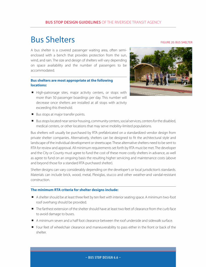
Bus SheltersA bus shelter is a covered passenger waiting area, often semi-enclosed with a bench that provides protection from the sun, wind, and rain. The size and design of shelters will vary depending on space availability and the number of passengers to be accommodated.
Bus shelters are most appropriate at the following locations:
■ High-patronage sites, major activity centers, or stops with more than 50 passenger boardings per day. This number will decrease once shelters are installed at all stops with activity exceeding this threshold.
■ Bus stops at major transfer points.
■ Bus stops located near senior housing, community centers, social services, centers for the disabled, medical centers, or other locations that may serve mobility-limited populations.
Bus shelters will usually be purchased by RTA prefabricated on a standardized vendor design from private shelter companies. Alternatively, shelters can be designed to fit the architectural style and landscape of the individual development or streetscape. These alternative shelters need to be sent to RTA for review and approval. All minimum requirements set forth by RTA must be met. The developer and the City or County must agree to fund the cost of these more costly shelters in advance, as well as agree to fund on an ongoing basis the resulting higher servicing and maintenance costs (above and beyond those for a standard RTA purchased shelter).
Shelter designs can vary considerably depending on the developer’s or local jurisdiction’s standards. Materials can include brick, wood, metal, Plexiglas, stucco and other weather-and vandal-resistant construction.
The minimum RTA criteria for shelter designs include:
■ A shelter should be at least three feet by ten feet with interior seating space. A minimum two-foot roof overhang should be provided.
■ The farthest extension of the shelter should have at least two feet of clearance from the curb face to avoid damage to buses.
■ A minimum seven and a half foot clearance between the roof underside and sidewalk surface.
■ Four feet of wheelchair clearance and maneuverability to pass either in the front or back of the shelter.
FIGURE 20: BUS SHELTER
BUS STOP DESIGN GUIDELINES OF THE RIVERSIDE TRANSIT AGENCY
– BUs stoP DesiGn 6.7 –
■ The shelter canopy should be waterproof with provisions for drainage away from passenger seating and bus loading sites.
■ A shelter should be situated near the front end of the stop zone to minimize passenger walk distances to board the bus and discourage the buses from stopping at the shelter instead of the front of the stop.
■ A shelter should not obstruct the vision of motorists and pedestrians or impede public/private walkways or driveways.
■ Use inside lighting with ten foot-candles intensity when possible. This increases passenger security and visibility of the shelter to drivers.
■ Display the shelter owner’s name and 24-hour telephone number for emergency purposes.
■ Utilize a solar power supply for lighting and other amenities such as real time information signs requiring a power source.
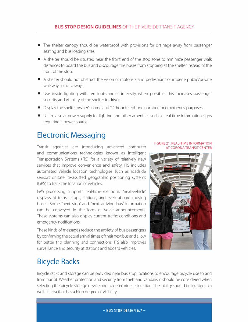
Electronic MessagingTransit agencies are introducing advanced computer and communications technologies known as Intelligent Transportation Systems (ITS) for a variety of relatively new services that improve convenience and safety. ITS includes automated vehicle location technologies such as roadside sensors or satellite-assisted geographic positioning systems (GPS) to track the location of vehicles.
GPS processing supports real-time electronic “next-vehicle” displays at transit stops, stations, and even aboard moving buses. Some “next stop” and “next arriving bus” information can be conveyed in the form of voice announcements. These systems can also display current traffic conditions and emergency notifications.
These kinds of messages reduce the anxiety of bus passengers by confirming the actual arrival times of their next bus and allow for better trip planning and connections. ITS also improves surveillance and security at stations and aboard vehicles.
Bicycle RacksBicycle racks and storage can be provided near bus stop locations to encourage bicycle use to and from transit. Weather protection and security from theft and vandalism should be considered when selecting the bicycle storage device and to determine its location. The facility should be located in a well-lit area that has a high degree of visibility.
FIGURE 21: REAL-TIME INFORMATION AT CORONA TRANSIT CENTER
BUS STOP DESIGN GUIDELINES OF THE RIVERSIDE TRANSIT AGENCY
– BUs stoP DesiGn 6.8 –
The location of any bicycle rack should be a sufficient distance away from surrounding structures and the curb to ensure easy circulation and access to bicycles and other amenities. Bicycle racks should be located at the periphery of the bus stop area away from where passengers will board and alight the bus.
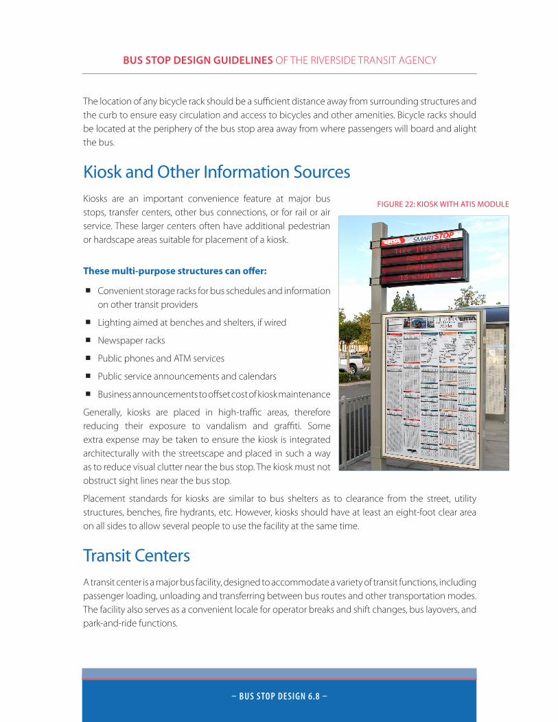
Kiosk and Other Information SourcesKiosks are an important convenience feature at major bus stops, transfer centers, other bus connections, or for rail or air service. These larger centers often have additional pedestrian or hardscape areas suitable for placement of a kiosk.
These multi-purpose structures can offer:
■ Convenient storage racks for bus schedules and information on other transit providers
■ Lighting aimed at benches and shelters, if wired
■ Newspaper racks
■ Public phones and ATM services
■ Public service announcements and calendars
■ Business announcements to offset cost of kiosk maintenance
Generally, kiosks are placed in high-traffic areas, therefore reducing their exposure to vandalism and graffiti. Some extra expense may be taken to ensure the kiosk is integrated architecturally with the streetscape and placed in such a way as to reduce visual clutter near the bus stop. The kiosk must not obstruct sight lines near the bus stop.
Placement standards for kiosks are similar to bus shelters as to clearance from the street, utility structures, benches, fire hydrants, etc. However, kiosks should have at least an eight-foot clear area on all sides to allow several people to use the facility at the same time.
Transit CentersA transit center is a major bus facility, designed to accommodate a variety of transit functions, including passenger loading, unloading and transferring between bus routes and other transportation modes. The facility also serves as a convenient locale for operator breaks and shift changes, bus layovers, and park-and-ride functions.
FIGURE 22: KIOSK WITH ATIS MODULE
BUS STOP DESIGN GUIDELINES OF THE RIVERSIDE TRANSIT AGENCY
– BUs stoP DesiGn 6.9 –
The transit center is the focal point of transit service in an area. It provides essential amenities for current passengers and increases the attractiveness of the development to prospective customers. Transit centers should be equipped with shelters, benches, bus bays, phones, trash receptacles, bus route information, and good lighting.
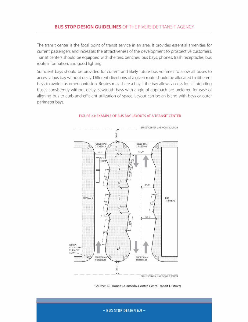
Sufficient bays should be provided for current and likely future bus volumes to allow all buses to access a bus bay without delay. Different directions of a given route should be allocated to different bays to avoid customer confusion. Routes may share a bay if the bay allows access for all intending buses consistently without delay. Sawtooth bays with angle of approach are preferred for ease of aligning bus to curb and efficient utilization of space. Layout can be an island with bays or outer perimeter bays.
FIGURE 23: EXAMPLE OF BUS BAY LAYOUTS AT A TRANSIT CENTER
Source: AC Transit (Alameda-Contra Costa Transit District)
BUS STOP DESIGN GUIDELINES OF THE RIVERSIDE TRANSIT AGENCY
– BUs stoP DesiGn 6.10 –
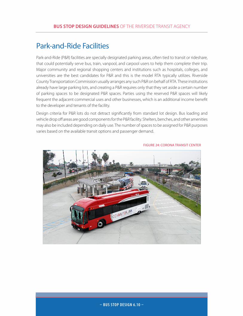
Park-and-Ride FacilitiesPark-and-Ride (P&R) facilities are specially designated parking areas, often tied to transit or rideshare, that could potentially serve bus, train, vanpool, and carpool users to help them complete their trip. Major community and regional shopping centers and institutions such as hospitals, colleges, and universities are the best candidates for P&R and this is the model RTA typically utilizes. Riverside County Transportation Commission usually arranges any such P&R on behalf of RTA. These institutions already have large parking lots, and creating a P&R requires only that they set aside a certain number of parking spaces to be designated P&R spaces. Parties using the reserved P&R spaces will likely frequent the adjacent commercial uses and other businesses, which is an additional income benefit to the developer and tenants of the facility.
Design criteria for P&R lots do not detract significantly from standard lot design. Bus loading and vehicle drop off areas are good components for the P&R facility. Shelters, benches, and other amenities may also be included depending on daily use. The number of spaces to be assigned for P&R purposes varies based on the available transit options and passenger demand.
FIGURE 24: CORONA TRANSIT CENTER
BUS STOP DESIGN GUIDELINES OF THE RIVERSIDE TRANSIT AGENCY
– BUs stoP DesiGn 6.11 –
Security and Maintenance ConsiderationsWell-lit, maintained, and secure bus stops are crucial to the image and performance of the transit system. Damaged property and trash build-up are attended to immediately by dedicated RTA Bus Stop Maintenance teams, to maintain comfort and a positive impression for transit patrons and the general public. Maintenance procedures are beyond the scope of these guidelines. However, RTA staff welcomes reporting of problems, constructive comments, or suggestions from all parties on this topic.
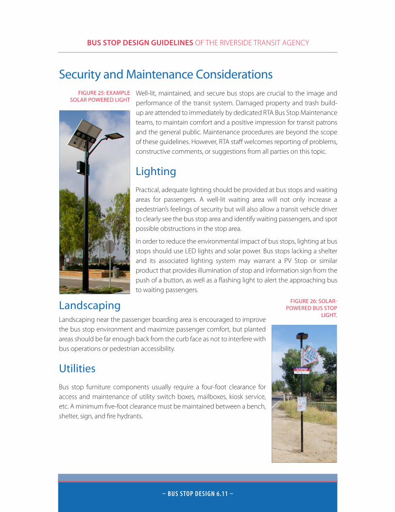
Lighting
Practical, adequate lighting should be provided at bus stops and waiting areas for passengers. A well-lit waiting area will not only increase a pedestrian’s feelings of security but will also allow a transit vehicle driver to clearly see the bus stop area and identify waiting passengers, and spot possible obstructions in the stop area.
In order to reduce the environmental impact of bus stops, lighting at bus stops should use LED lights and solar power. Bus stops lacking a shelter and its associated lighting system may warrant a PV Stop or similar product that provides illumination of stop and information sign from the push of a button, as well as a flashing light to alert the approaching bus to waiting passengers.
LandscapingLandscaping near the passenger boarding area is encouraged to improve the bus stop environment and maximize passenger comfort, but planted areas should be far enough back from the curb face as not to interfere with bus operations or pedestrian accessibility.
Utilities
Bus stop furniture components usually require a four-foot clearance for access and maintenance of utility switch boxes, mailboxes, kiosk service, etc. A minimum five-foot clearance must be maintained between a bench, shelter, sign, and fire hydrants.
FIGURE 25: EXAMPLE SOLAR POWERED LIGHT
FIGURE 26: SOLAR-POWERED BUS STOP
LIGHT.
BUS STOP DESIGN GUIDELINES OF THE RIVERSIDE TRANSIT AGENCY
– BUiLDinG sUstAinABLe CoMMUnities 7.1 –
Building Sustainable CommunitiesRiverside Transit Agency is committed to supporting the initiatives of other government agencies to create sustainable communities in western Riverside County. Under SB 375, the State of California has laid out clear climate action goals to reduce greenhouse gas emissions and improve air quality through coordinated transportation and land use planning. In response to SB 375, the Southern California Association of Governments (SCAG) produced a 2012-2035 Regional Transportation Plan/Sustainable Communities Strategy (RTP/SCS) report which serves as a guide for land use and transportation planning in western Riverside County.
The plan calls for encouraging land use and growth patterns that facilitate motorized and non-motorized transit. It focuses on “Better Placemaking,” the process of developing options for locations where people can live and work that focus on more compact development, varied housing options, bike and pedestrian improvements, and efficient transportation infrastructure. It specifically calls for supporting transit use and ridership by creating pedestrian-friendly environments and higher density development patterns in close proximity to existing transit infrastructure.
Developers should consider the guidelines laid forth in the RTP/SCS.
Depending on the size, layout, and number of buildings in a development, the following transit-friendly design elements should be incorporated where applicable:
■ Land uses are mixed and may include a combination of residential, commercial, and entertainment activities.
■ Development has higher densities with limited parking and dispersed growth.
■ Location within a ten-to-fifteen-minute walking distance of transit.
■ Neighborhood focal point: Open spaces or plazas near the station function as community gathering spots.
■ Pedestrian orientation: Streets and open spaces are friendly to pedestrians.
■ Create new developments along existing or proposed transit corridors.
■ Provide a space for a bus stop near major intersections or the primary entrance to the project off the arterial.
■ Avoid walling off larger complexes to provide easy pedestrian access to bus stops on perimeter streets. Where walls cannot be avoided, provide pedestrian pathways allowing direct pedestrian access from interior streets to the bus stops.
For the full 2012-2035 Regional Transportation Plan/Sustainable Communities Strategy please access the following address: www.rtpscs.scag.ca.gov/Documents/2012/final/f2012RTPSCS.pdf.
BUS STOP DESIGN GUIDELINES OF THE RIVERSIDE TRANSIT AGENCY
– ConCLUsion 8.1 –
ConclusionThis document provides an overview of planning for bus transit compatibility. For a copy of this document and to learn more about the transit standards in these Guidelines, please contact the RTA Planning Staff at:
Riverside Transit Agency 1825 Third St Riverside, CA 92507 Phone: 951-565-5002 Website: www.riversidetransit.com
These Guidelines are by no means exhaustive of the planning considerations surrounding public transit. Further information can be found at the following resources:
Transit Planning Resources*ORGANIZATION CONTACT INFORMATION
AMERICAN PUBLIC TRANSIT ASSOCIATION http://www.apta.com
CALIFORNIA ASSOCIATION OF COORDINATED TRANSIT http://www.calact.org/home
SOUTHERN CALIFORNIA ASSOCIATION OF GOVERNMENTS REGIONAL TRANSPORTATION PLAN
http://rtpscs.scag.ca.gov/Pages/default.aspx
CALIFORNIA AIR RESOURCES BOARD SB375 http://www.arb.ca.gov/cc/sb375/sb375.htm
NATIONAL TRANSIT INSTITUTE http://www.ntionline.com/
CALIFORNIA LOCAL GOVERNMENT COMMISSION http://www.lgc.org/
PLANETIZEN http://www.planetizen.com/
PROJECT FOR PUBLIC SPACES http://pps.org/Transportation/
NATIONAL ASSOCIATION OF CITY TRANSPORTATION OFFICIALS URBAN STREET DESIGN GUIDE
http://nacto.org/usdg/
*These sources and Internet sites are representative samples provided as a courtesy to interested parties. Inclusion in the list is not necessarily connotative of universal and total agreement with or endorsement of a product, service, or strategy by RTA. All information found on the individual internet sites is the responsibility of parties other than RTA.
TABLE 4: TRANSIT PLANNING RESOURCES
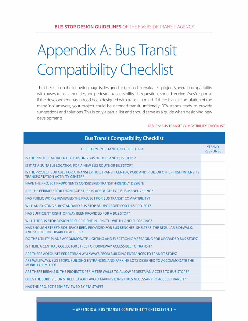
BUS STOP DESIGN GUIDELINES OF THE RIVERSIDE TRANSIT AGENCY
– APPenDiX A: BUs tRAnsit CoMPAtiBiLit Y CHeCKList 9.1 –
Appendix A: Bus Transit Compatibility ChecklistThe checklist on the following page is designed to be used to evaluate a project’s overall compatibility with buses, transit amenities, and pedestrian accessibility. The questions should receive a “yes” response if the development has indeed been designed with transit in mind. If there is an accumulation of too many “no” answers, your project could be deemed transit-unfriendly. RTA stands ready to provide suggestions and solutions. This is only a partial list and should serve as a guide when designing new developments.
Bus Transit Compatibility Checklist
DEVELOPMENT STANDARD OR CRITERIAYES/NO
RESPONSE
IS THE PROJECT ADJACENT TO EXISTING BUS ROUTES AND BUS STOPS?
IS IT AT A SUITABLE LOCATION FOR A NEW BUS ROUTE OR BUS STOP?
IS THE PROJECT SUITABLE FOR A TRANSFER HUB, TRANSIT CENTER, PARK-AND-RIDE, OR OTHER HIGH-INTENSITY TRANSPORTATION ACTIVITY CENTER?
HAVE THE PROJECT PROPONENTS CONSIDERED TRANSIT-FRIENDLY DESIGN?
ARE THE PERIMETER OR FRONTAGE STREETS ADEQUATE FOR BUS MANEUVERING?
HAS PUBLIC WORKS REVIEWED THE PROJECT FOR BUS TRANSIT COMPATIBILITY?
WILL AN EXISTING SUB-STANDARD BUS STOP BE UPGRADED FOR THIS PROJECT?
HAS SUFFICIENT RIGHT-OF-WAY BEEN PROVIDED FOR A BUS STOP?
WILL THE BUS STOP DESIGN BE SUFFICIENT IN LENGTH, WIDTH, AND SURFACING?
HAS ENOUGH STREET-SIDE SPACE BEEN PROVIDED FOR BUS BENCHES, SHELTERS, THE REGULAR SIDEWALK, AND SUFFICIENT DISABLED ACCESS?
DO THE UTILITY PLANS ACCOMMODATE LIGHTING AND ELECTRONIC MESSAGING FOR UPGRADED BUS STOPS?
IS THERE A CENTRAL COLLECTOR STREET OR DRIVEWAY ACCESSIBLE TO TRANSIT?
ARE THERE ADEQUATE PEDESTRIAN WALKWAYS FROM BUILDING ENTRANCES TO TRANSIT STOPS?
ARE WALKWAYS, BUS STOPS, BUILDING ENTRANCES, AND PARKING LOTS DESIGNED TO ACCOMMODATE THE MOBILITY-LIMITED?
ARE THERE BREAKS IN THE PROJECT’S PERIMETER WALLS TO ALLOW PEDESTRIAN ACCESS TO BUS STOPS?
DOES THE SUBDIVISION STREET LAYOUT AVOID MAKING LONG HIKES NECESSARY TO ACCESS TRANSIT?
HAS THE PROJECT BEEN REVIEWED BY RTA STAFF?
TABLE 5: BUS TRANSIT COMPATIBILITY CHECKLIST
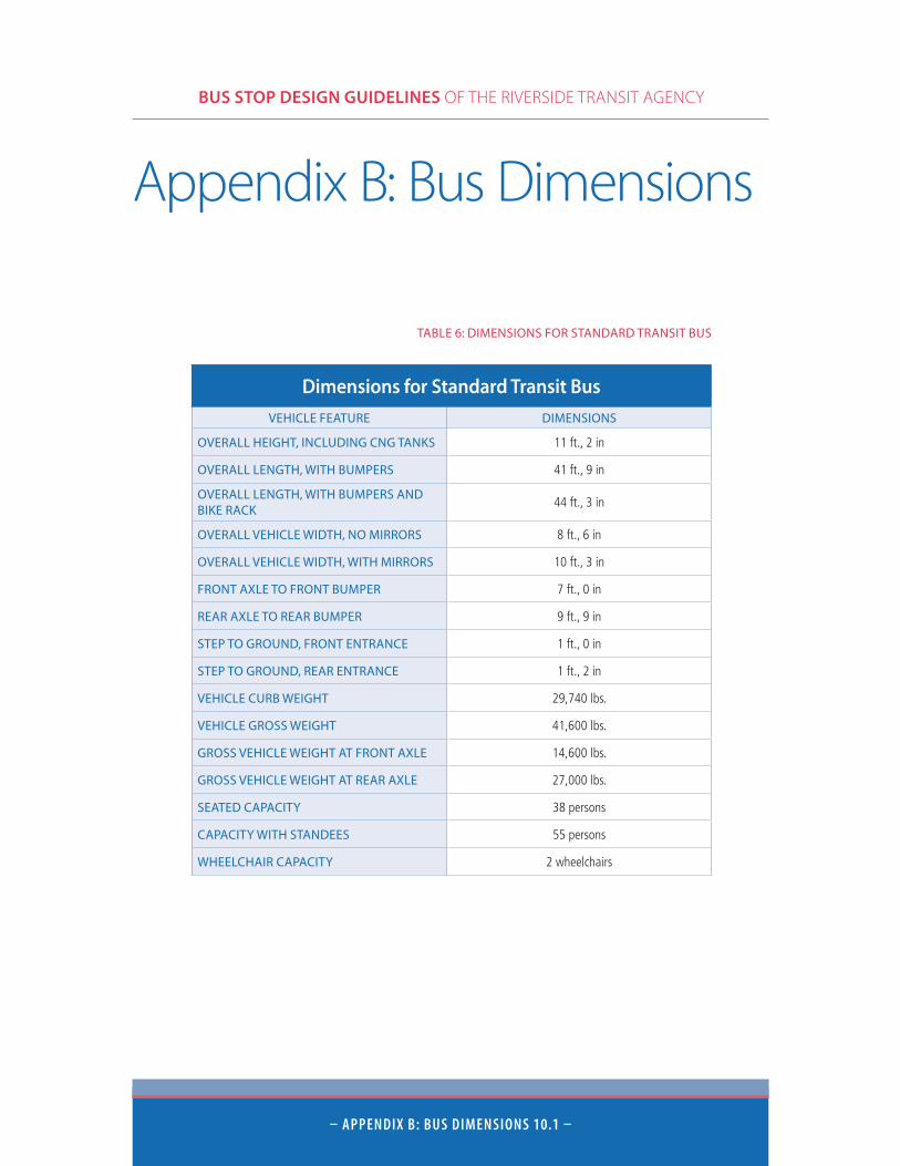
BUS STOP DESIGN GUIDELINES OF THE RIVERSIDE TRANSIT AGENCY
– APPenDiX B: BUs DiMensions 10.1 –
Dimensions for Standard Transit BusVEHICLE FEATURE DIMENSIONS
OVERALL HEIGHT, INCLUDING CNG TANKS 11 ft., 2 in
OVERALL LENGTH, WITH BUMPERS 41 ft., 9 in
OVERALL LENGTH, WITH BUMPERS AND BIKE RACK
44 ft., 3 in
OVERALL VEHICLE WIDTH, NO MIRRORS 8 ft., 6 in
OVERALL VEHICLE WIDTH, WITH MIRRORS 10 ft., 3 in
FRONT AXLE TO FRONT BUMPER 7 ft., 0 in
REAR AXLE TO REAR BUMPER 9 ft., 9 in
STEP TO GROUND, FRONT ENTRANCE 1 ft., 0 in
STEP TO GROUND, REAR ENTRANCE 1 ft., 2 in
VEHICLE CURB WEIGHT 29,740 lbs.
VEHICLE GROSS WEIGHT 41,600 lbs.
GROSS VEHICLE WEIGHT AT FRONT AXLE 14,600 lbs.
GROSS VEHICLE WEIGHT AT REAR AXLE 27,000 lbs.
SEATED CAPACITY 38 persons
CAPACITY WITH STANDEES 55 persons
WHEELCHAIR CAPACITY 2 wheelchairs
TABLE 6: DIMENSIONS FOR STANDARD TRANSIT BUS
Appendix B: Bus Dimensions
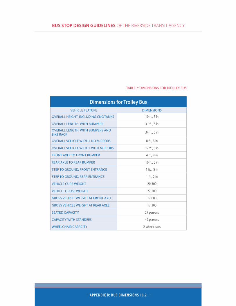
BUS STOP DESIGN GUIDELINES OF THE RIVERSIDE TRANSIT AGENCY
– APPenDiX B: BUs DiMensions 10.2 –
Dimensions for Trolley BusVEHICLE FEATURE DIMENSIONS
OVERALL HEIGHT, INCLUDING CNG TANKS 10 ft., 6 in
OVERALL LENGTH, WITH BUMPERS 31 ft., 6 in
OVERALL LENGTH, WITH BUMPERS AND BIKE RACK
34 ft., 0 in
OVERALL VEHICLE WIDTH, NO MIRRORS 8 ft., 6 in
OVERALL VEHICLE WIDTH, WITH MIRRORS 12 ft., 6 in
FRONT AXLE TO FRONT BUMPER 4 ft., 8 in
REAR AXLE TO REAR BUMPER 10 ft., 0 in
STEP TO GROUND, FRONT ENTRANCE 1 ft., .5 in
STEP TO GROUND, REAR ENTRANCE 1 ft., 2 in
VEHICLE CURB WEIGHT 20,300
VEHICLE GROSS WEIGHT 27,200
GROSS VEHICLE WEIGHT AT FRONT AXLE 12,000
GROSS VEHICLE WEIGHT AT REAR AXLE 17,300
SEATED CAPACITY 27 persons
CAPACITY WITH STANDEES 49 persons
WHEELCHAIR CAPACITY 2 wheelchairs
TABLE 7: DIMENSIONS FOR TROLLEY BUS
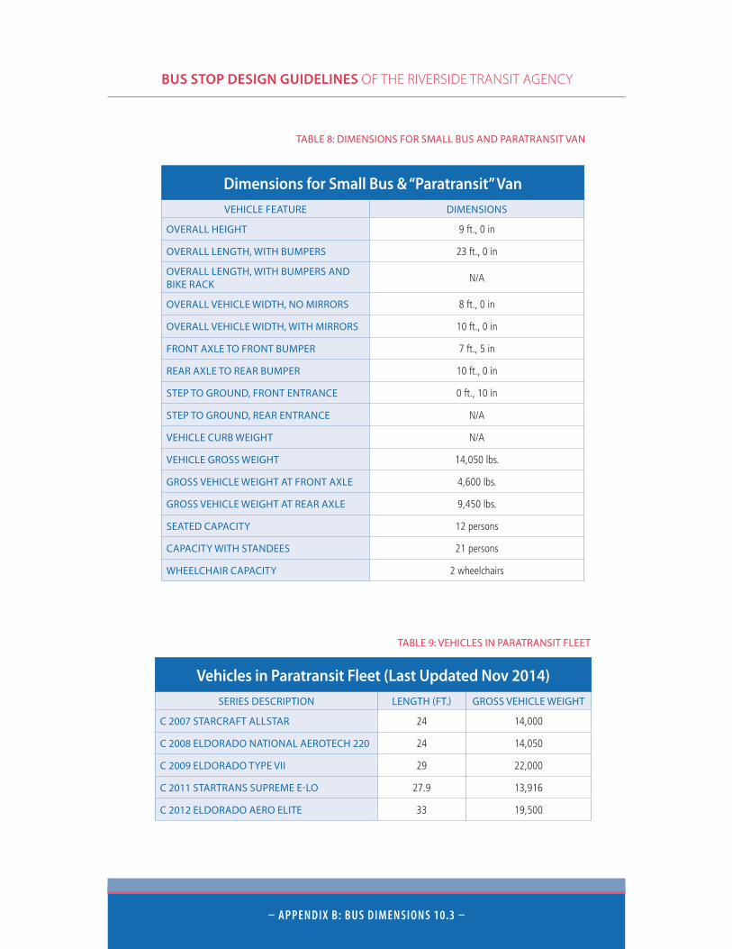
BUS STOP DESIGN GUIDELINES OF THE RIVERSIDE TRANSIT AGENCY
– APPenDiX B: BUs DiMensions 10.3 –
Dimensions for Small Bus & “Paratransit” VanVEHICLE FEATURE DIMENSIONS
OVERALL HEIGHT 9 ft., 0 in
OVERALL LENGTH, WITH BUMPERS 23 ft., 0 in
OVERALL LENGTH, WITH BUMPERS AND BIKE RACK
N/A
OVERALL VEHICLE WIDTH, NO MIRRORS 8 ft., 0 in
OVERALL VEHICLE WIDTH, WITH MIRRORS 10 ft., 0 in
FRONT AXLE TO FRONT BUMPER 7 ft., 5 in
REAR AXLE TO REAR BUMPER 10 ft., 0 in
STEP TO GROUND, FRONT ENTRANCE 0 ft., 10 in
STEP TO GROUND, REAR ENTRANCE N/A
VEHICLE CURB WEIGHT N/A
VEHICLE GROSS WEIGHT 14,050 lbs.
GROSS VEHICLE WEIGHT AT FRONT AXLE 4,600 lbs.
GROSS VEHICLE WEIGHT AT REAR AXLE 9,450 lbs.
SEATED CAPACITY 12 persons
CAPACITY WITH STANDEES 21 persons
WHEELCHAIR CAPACITY 2 wheelchairs
TABLE 8: DIMENSIONS FOR SMALL BUS AND PARATRANSIT VAN
Vehicles in Paratransit Fleet (Last Updated Nov 2014)SERIES DESCRIPTION LENGTH (FT.) GROSS VEHICLE WEIGHT
C 2007 STARCRAFT ALLSTAR 24 14,000
C 2008 ELDORADO NATIONAL AEROTECH 220 24 14,050
C 2009 ELDORADO TYPE VII 29 22,000
C 2011 STARTRANS SUPREME E-LO 27.9 13,916
C 2012 ELDORADO AERO ELITE 33 19,500
TABLE 9: VEHICLES IN PARATRANSIT FLEET
BUS STOP DESIGN GUIDELINES OF THE RIVERSIDE TRANSIT AGENCY
– APPenDiX C: GLossARY oF teRMs 11.1 –
Appendix C: Glossary of TermsThis glossary provides a partial list of selected terms, defining words or phrases that are frequently used or heard in transportation and transit planning.
Activity center: A concentration of development in a small geographic area, resulting in high density employment and retail activity with high levels of demand for services, including transportation.
ADA compliance: Characteristics of transit equipment, service and boarding areas that comply with the Americans With Disabilities Act (ADA) of 1990 and subsequent amendments. ADA is legislation that mandates equal access to all public transportation services, regardless of mobility status. The ADA requires that fixed-route transit be accessible and that paratransit (curb-to-curb) service be provided in the same geographic areas on the same days and hours as the fixed route service.
Alightings: Passengers getting off a transit vehicle at a bus stop.
Amenities: Specific passenger or bus features that enhance public transportation, including lighted, paved, handicapped-accessible walkways, shelters, benches, waiting pads, turnouts and bus stop signs.
Articulated bus: A high capacity (60 to 75 seated passengers) transit vehicle consisting of two sections hinged to each other, permitting the vehicle to turn within a relatively short turning radius, yet with one engine and one driver.
ATIS: Advanced Travel Information Systems provide real-time status of transit vehicles and services, such as the predicted time of arrival of the next bus or buses. The ATIS data can be found on the internet, handheld devices, message boards, or public kiosks at transit centers.
Best Practices: An approach to transit planning that requires adherence to nationally recognized industry standards for physical facilities and services.
Boardings: Passengers getting on a transit vehicle at a bus stop.
BRT: Bus Rapid Transit offers rail-like transit on an upgraded, rubber-tired bus vehicle. BRT is characterized by attention to major transit corridors, simple but frequent service, preferential traffic light controls and a reduced number of stops, providing an overall express-like experience.
Bus bench: A bench that can accommodate three or more persons and is placed at a bus stop for use by waiting passengers.
Bus pad: An area of the street, adjacent to the bus stop that is concrete-paved.
Bus shelter: A covered passenger waiting area, often semi-enclosed with benches, that provides protection from the elements.
BUS STOP DESIGN GUIDELINES OF THE RIVERSIDE TRANSIT AGENCY
– APPenDiX C: GLossARY oF teRMs 11.2 –
Bus stop: A linear curbside area that is specially designated for buses stopping to board and/or alight passengers, and is accompanied by a red curb zone and/or a “No Parking” sign.
Bus stop spacing: The linear distance between individual bus stops.
Bus turning radii: The dimensions necessary to accommodate bus turning at intersections, parking lots, transit centers and elsewhere.
Bus turnout: A bus stop located in a recessed curb area, separated from traffic. Also known as “bus bay” or “bus berth”. Collector streets: Streets that gather and disperse traffic between larger arterial highways and the local distributor streets.
Commuter bus: Transit over mostly major highways, with few stops, and with service provided primarily at peak morning and evening hours.
Dial-A-Ride: Curb to curb bus service for the general public as well as those individuals having special needs such as elderly persons or persons with disabilities.
Dwell time: The time a bus spends at a stop, primarily for passengers to get on and off, measured as the interval between its stopping and starting.
Egress: Motion of a person or vehicle leaving or exiting a place. Both passengers and buses make their own manner of egress movements.
Far side: A location for bus stop placed immediately beyond the intersection.
Fixed-route bus service: Transit provided along dependable and defined routes with published schedules and stops at designated locations.
Headway: The frequency interval between the passing of successive buses moving along the same route in the same direction, usually expressed in minutes.
High-rise development: A concentration of development characterized by multi-story buildings in excess of six stories. Clusters of high-rise buildings are frequently found in activity centers.
Ingress: Motion of a person or vehicle entering a place. Both passengers and buses make ingress movements.
ITS: Intelligent Transportation Systems will integrate bus operations and planning with higher levels of new technology. ITS is characterized by GPS tracking of vehicles, on-board cameras, linkage with highway and police agencies and accurate monitoring of passenger boarding patterns.
Layover: Additional time included into a bus schedule between arrivals and departures, used for recovery of delays, driver breaks, and preparation for the return trip.
Mid-block bus stop: A transit stop located between distant intersections.
Mobility-limited: Individuals having a physical or mental impairment that adversely affects their ability to use various types of transportation, including public transit.
Mode shift: During a complete trip, the traveler will often divide the means of mobility among various conveyances. Various modes include walking, bicycling, bus, rail, single-occupancy vehicles,
BUS STOP DESIGN GUIDELINES OF THE RIVERSIDE TRANSIT AGENCY
– APPenDiX C: GLossARY oF teRMs 11.3 –
shared vehicles, carpools, ferry, or aircraft. Even a split between different kinds of buses –local or express buses – is considered a mode shift.
Near side: The location for a bus stop that is placed on the approach side of an intersection.
Overhang: Portion of the bus body extending beyond the front or rear axle.
Queue jumper: A short section of preferential traffic lane that permits transit vehicles to bypass an automobile queue at a traffic signal or congested section of the roadway.
Park-and-ride-lot: A designated parking area provided for bus, van pool, and car pool users to park and leave their cars and to continue their trip in a multi-occupant vehicle, such as a car pool, van pool or bus.
Pedestrian accessway: A lighted, paved and handicap-accessible walkway that provides convenient access to transit facilities and bus stops from adjacent developments.
Red curb area: A street curb, painted red to designate the zone for bus use only, that prohibits parking or stopping by all other vehicles.
Road grade: The maximum slope or grade that a standard 40-foot transit bus can negotiate safely on a street, highway or ramp.
Transit-friendly or Transit-oriented development: A design approach to residential or commercial development that densifies around high quality transit service with high frequency service, safe and comfortable transit stops, clean fuel vehicles, to attract new and higher transit ridership.
Transit furniture: Objects provided at a bus stop or transit center for the comfort and convenience of waiting passengers, such as a shelter, bench, trash receptacle, or other components.
Transportation modeling: The combining of data from traffic and land use patterns, road capacities, traffic counts, population, employment information and other data into scenarios that describe existing and future travel behavior.
Travel lane: A lane devoted exclusively to vehicular traffic.
Trip generator: A land use or discrete activity that by nature of its operations tends to create a significant amount of travel. Also referred to as a ‘trip attractor’.
Wheelchair ramp: A slightly sloping paved area designed and designated to provide handicapped access across height and texture differences such as side-walks, stairs, or other barriers to free movement of wheelchairs. RTA buses and vans are equipped with special mechanical ramps that are controlled by operators and lowered from the bus door to allow wheelchair patrons to safely and easily board buses.

BUS STOP DESIGN GUIDELINES OF THE RIVERSIDE TRANSIT AGENCY
– APPenDiX C: GLossARY oF teRMs 11.4 –
BUS STOP DESIGN GUIDELINES OF THE RIVERSIDE TRANSIT AGENCY
– APPenDiX C: GLossARY oF teRMs 11.5 –

BUS STOP DESIGN GUIDELINES OF THE RIVERSIDE TRANSIT AGENCY
– APPenDiX C: GLossARY oF teRMs 11.6 –