Embed Size (px)
Citation preview
NOTICE: This publication is available digitally on the AFDPO WWW site at: http://afpubs.hq.af.mil. Ifyou lack access, contact your Publishing Distribution Office (PDO).
BY ORDER OF THE SECRETARY OF THE AIR FORCE
AIR FORCE PAMPHLET 32-1186
1 AUGUST 1999Certified Current 28 April 2014
Civil Engineering
VALVE-REGULATED LEAD-ACID BATTERIESFOR STATIONARY APPLICATIONS
OPR: HQ AFCESA/CESM (Mr. Raymond N. Hansen)
Certified by: HQ AFCESA/CC(Col H. Dean Bartel)
Pages: 72Distribution: F
This pamphlet implements AFPD 32-10, Installations and Facilities. It prescribes criteria for the applica-tion, selection, installation, and maintenance for valve-regulated lead-acid (VRLA) batteries on Air Forceinstallations. Refer to AFJMAN 32-1280(I), Facilities Engineering, Electrical Exterior Facilities, and toAFJMAN 32-1281(I), Facilities Engineering, Electrical Interior Facilities, for general storage batterycriteria. Users should send comments and suggested improvements on AF Form 847, Recommendationfor Change of Publication, through major commands (MAJCOM) and HQ AFCESA/CESM, 139 BarnesDr, Tyndall AFB FL 32403-5319 to HQ USAF/ILEO, 1260 Air Force Pentagon, Washington DC20330-1260.
Chapter 1— PURPOSE AND APPLICABILITY 4
1.1. Purpose ....................................................................................................................... 4
1.2. Need for Special Maintenance Procedures ................................................................ 4
1.3. Material Covered ....................................................................................................... 4
1.4. Applicability .............................................................................................................. 4
Chapter 2— LEAD-ACID BATTERY FUNDAMENTALS 5
2.1. Electrochemical Process ............................................................................................ 5
2.2. Lead-Acid Battery Construction ................................................................................ 6
Figure 2.1. Typical Positive and Negative Grids ......................................................................... 8
Figure 2.2. Typical Positive and Negative Pasted Flat Plate ....................................................... 10
Figure 2.3. Plate Assembly in Cell ............................................................................................... 12
2.3. Electrical Characteristics ........................................................................................ 14
Figure 2.4. Typical Cell Voltage Profile During Constant Current Discharge ............................ 15
2 AFPAM32-1186 1 AUGUST 1999
8
32
39
41
44
44
Figure 2.5. Typical Voltage Dip at Beginning of Discharge ....................................................... 16
Table 2.1. Typical Capacity Rating ............................................................................................ 17
2.4. Valve-Regulated Lead-Acid (VRLA) Battery Design ........................................... 18
Figure 2.6. Typical VRLA Cell .................................................................................................... 19
Figure 2.7. VRLA Battery Installed Horizontally (Shown With and Without Protective Covers) 20
Figure 2.8. Vented Cell Plate Polarization ................................................................................... 25
Figure 2.9. VRLA Cell Plate Polarization .................................................................................... 26
Chapter 3— VRLA BATTERY AGING, DEGRADATION, AND FAILURE 28
3.1. Introduction ................................................................................................................ 28
3.2. Traditional Lead-Acid Battery Aging .................................................................... 2
Figure 3.1. Ideal Battery Life Curve ............................................................................................ 29
Figure 3.2. Possible Variations From the Ideal Battery Life Curve ............................................. 30
Figure 3.3. Temperature Effect on Lead-Acid Battery Life ......................................................... 31
3.3. VRLA Battery Failure Modes ................................................................................
Figure 3.4. Thermal Runaway Sequence ..................................................................................... 34
Figure 3.5. Float Voltage Variation Observed at One Site .......................................................... 37
Chapter 4— INDUSTRY STANDARDS APPLICABLE TO VRLA BATTERIES 39
4.1. Introduction ................................................................................................................ 39
4.2. IEEE 1187-1996 ........................................................................................................ 39
4.3. IEEE 1188-1996 ........................................................................................................
4.4. Other IEEE Standards ............................................................................................
Chapter 5— APPLICATION CONSIDERATIONS 42
5.1. VRLA Battery Desirable Features ............................................................................. 42
5.2. Allowed Applications ................................................................................................ 42
5.3. Excluded Applications ............................................................................................... 42
5.4. Vented Lead-Acid Batteries ....................................................................................... 43
5.5. Monitoring and Maintenance ..................................................................................... 43
Chapter 6— PERSONNEL AND EQUIPMENT SAFETY 44
6.1. General Precautions ................................................................................................
6.2. Explosion Hazards ...................................................................................................
AFPAM32-1186 1 AUGUST 1999 3
46
49
54
60
61
64
66
67
67
68
68
6.3. Short Circuit Hazards ............................................................................................. 45
Chapter 7— PERIODIC MAINTENANCE 46
7.1. VRLA Battery Inspections That Can and Cannot Be Performed ....................... 46
7.2. Monthly Inspection ..................................................................................................
Figure 7.1. Signs of Electrolyte Leakage From a VRLA Battery ................................................ 48
7.3. Quarterly Inspection ................................................................................................
Figure 7.2. Internal Conductance Tester ...................................................................................... 51
Figure 7.3. Internal Impedance Tester ......................................................................................... 52
Figure 7.4. Internal Resistance Tester .......................................................................................... 52
7.4. Annual Inspection ....................................................................................................
Figure 7.5. Proper Micro-Ohmmeter Measurement ..................................................................... 56
Figure 7.6. Single Terminal Post Resistance Measurement ......................................................... 57
Figure 7.7. Two Terminal Post Resistance Measurement ............................................................ 57
Figure 7.8. Cable Bolted to Terminal Post ................................................................................... 58
Figure 7.9. Inter-Tier or Inter-Rack Resistance Measurement ..................................................... 58
7.5. Special Inspections ...................................................................................................
Chapter 8— PERIODIC TESTS 61
8.1. Capacity Discharge Test (Performance Test) .......................................................
Figure 8.1. Typical Cell Voltage Measurement ........................................................................... 63
8.2. Continuity Test .........................................................................................................
Chapter 9— INSTALLATION AND REPLACEMENT 66
9.1. Replacement Criteria ................................................................................................. 66
9.2. Battery Size Verification .........................................................................................
9.3. Design Verification for a Replacement Battery Larger Than the Original ....... 67
9.4. Check of Other Equipment .....................................................................................
9.5. Maintenance Checks of a New Battery ..................................................................
9.6. Warranty Considerations ........................................................................................
9.7. Life Cycle Management ...........................................................................................
Attachment 1— GLOSSARY OF REFERENCES AND SUPPORTING INFORMATION 70
4 AFPAM32-1186 1 AUGUST 1999
Chapter 1
PURPOSE AND APPLICABILITY
1.1. Purpose. This AFMAN has been issued to provide users with application, selection, installation, andmaintenance guidance for valve-regulated lead-acid (VRLA) batteries. The purpose of the requirementscontained in this AFMAN is to assure the most reliable system possible with VRLA batteries. VRLA bat-teries are relatively new to the market and they have exhibited different aging and failure modes than tra-ditional vented batteries. For this reason, this AFMAN provides a detailed explanation of VRLA batterydesign, degradation, and failure. Traditional vented lead-acid batteries are discussed only to the degreenecessary to explain key differences between vented and VRLA batteries. The background information iseducational in nature and is intended to provide insight into the purposes of the requirements for VRLAbattery application, installation, and maintenance.
1.2. Need for Special Maintenance Procedures. VRLA batteries are more likely to fail before the endof their stated service life than are traditional vented lead-acid batteries, and their failure can be harder todetect by conventional methods. The maintenance requirements contained in this AFPAM are necessaryto detect the onset of individual cell failures before the reliability of the entire battery is jeopardized.Detailed maintenance procedures are included to facilitate the required maintenance.
1.3. Material Covered. The complete life cycle of VRLA batteries is covered in this AFPAM, includingselection, application, installation, periodic maintenance, testing, and eventual replacement.
1.4. Applicability:
1.4.1. Authority. This AFPAM complies with Air Force Instruction 32-1080, Electric Power Sys-tems.
1.4.2. Type of Systems Covered. Compliance with the AFPAM is mandatory for VRLA stationarybatteries in exterior and interior electrical systems that are the responsibility of the Base Civil Engi-neer at all facilities and bases. This AFMAN does not apply to motive power, air ground equipment(AGE), or aircraft batteries.
AFPAM32-1186 1 AUGUST 1999 5
Chapter 2
LEAD-ACID BATTERY FUNDAMENTALS
2.1. Electrochemical Process:
2.1.1. A battery provides electrical power by converting its stored chemical energy into electricalenergy. This energy conversion is achieved by a chemical reaction in the battery that releases elec-trons. The process is reversible in a stationary battery. If a load is placed across the battery terminals,the chemical reaction produces electrical power. If electrical energy is directed into the battery(charging the battery), the chemical reaction reverses and restores the battery to a fully charged condi-tion.
2.1.2. The generation of electrical current from a cell originates from a difference in electrochemicalpotential between two compounds inside the cell that are not in direct contact, but are connected by anelectrically conducting medium. The two compounds are installed in the cell as positive and negativeplates, and the connecting medium between the two plates is referred to as the electrolyte. As theplate materials chemically react with the electrolyte, a potential difference is created between theplates and the electrolyte. The positive plates have a positive potential in relation to the electrolyte;the negative plates have a negative potential in relation to the electrolyte. The electrochemical pro-cess between the plates and electrolyte creates a voltage between the positive and negative plates ofthe cell.
2.1.3. In a lead-acid battery, the positive plate material is lead dioxide (PbO2) and the negative platematerial is lead (Pb). The plate material is often referred to as the active material. The electrolyte isa sulfuric acid solution (H2SO4).
2.1.4. The overall chemical reaction within a lead-acid battery is described as the full cell reaction,and is given by:
PbO2 + Pb + 2H2SO4 ↔ 2PbSO4 + 2H2O
2.1.5. Several observations can be made regarding the electrochemical process of a lead-acid battery:
2.1.5.1. When the battery terminals are connected to an external circuit, the current that flowsfrom the battery is proportional to the potential difference of the plates and is limited mainly bythe circuit resistance. The external connection provides a flow path for electrons, and therebyfacilitates the conditions needed to sustain the chemical reaction. If the external circuit resistanceis too small (short circuit), the current flow is limited mainly by the efficiency of the chemicalreaction.
2.1.5.2. The sulfuric acid electrolyte is consumed in the discharge reaction and water is produced.Thus, the acid is continuously diluted during discharge. The decreasing concentration of acid inthe electrolyte represents a decrease in the state of charge of the battery.
2.1.5.3. The active materials of both plates, lead and lead dioxide, are consumed during the dis-charge reaction and lead sulfate is produced. The lead sulfate is deposited onto both positive andnegative plates as it is produced. Thus, the material composition of the plates changes during dis-charge.
6 AFPAM32-1186 1 AUGUST 1999
2.1.5.4. The cell becomes less able to sustain the chemical reaction as the concentration of activematerial and acid decreases during discharge. Eventually, the quantity of active material or sulfu-ric acid (depending on which is limiting) is not sufficient to maintain the reaction at a rate that pro-duces measurable current flow.
2.1.5.5. The injection of electrical energy into a battery during charging reverses the chemicalreaction in the cell. To drive the chemical reaction in the charge direction, the battery must absorbenergy. Thus, during charging, electrical energy is transformed to chemical energy.
2.1.5.6. Because the electrolyte is conductive, the chemical reaction can occur without an externalcircuit, and is referred to as self-discharge or local action. Self-discharge is usually a slow pro-cess; an open-circuit cell might take several months to over a year before it fully discharges.
2.2. Lead-Acid Battery Construction:
2.2.1. Basic Construction:
2.2.1.1. A lead-acid battery consists of individual cells connected together to provide the desiredoutput voltage. A single cell consists of positive and negative plates assembled inside a containerthat is filled with a sulfuric acid electrolyte. The following basic components are assembled tomake a cell:
2.2.1.1.1. Container
2.2.1.1.2. Lead dioxide positive plates
2.2.1.1.3. Lead negative plates
2.2.1.1.4. Separators and retainers
2.2.1.1.5. Sulfuric acid electrolyte
2.2.1.2. These components make up the basic building blocks of a lead-acid cell; their design andthe method of construction vary according to the intended application. The following characteris-tics are commonly changed to tailor a battery to a specific application:
2.2.1.2.1. Plate and grid alloy material, alloy concentration, or geometry
2.2.1.2.2. Number of plates
2.2.1.2.3. Separator material type and thickness
2.2.1.2.4. Retainer design
2.2.1.2.5. Electrolyte specific gravity
2.2.1.2.6. Post seal design (copper inserts) or number of posts
2.2.2. Plate Design:
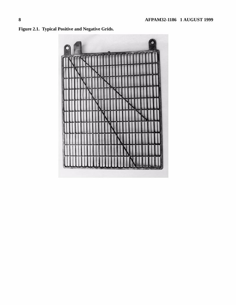
2.2.2.1. Lead-acid cells are defined by their plate construction and the alloys used in the plates.The pasted flat plate is the most common design for vented and VRLA cells. When a pasted flatplate is assembled, lead oxide (PbO) paste is applied to a lead alloy grid structure, and thenallowed to dry in place. The lead oxide paste is called the active material. A grid structure con-taining the active material is a plate. Typical grids for a pasted flat plate are shown in figure 2.1..After the lead oxide paste has dried, the plates are immersed in a dilute sulfuric acid solution and

AFPAM32-1186 1 AUGUST 1999 7
current is passed through them, with opposite polarities for the positive and negative plates. Thelead oxide (PbO) is converted to lead dioxide (PbO2) in the positive plates and to lead (Pb) in thenegative plates. Figure 2.2. shows typical pasted flat plates with the active material in place.
8 AFPAM32-1186 1 AUGUST 1999
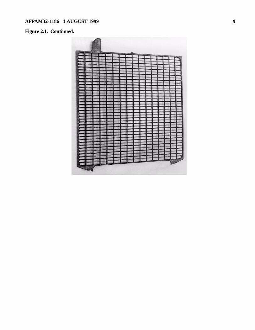
Figure 2.1. Typical Positive and Negative Grids.
AFPAM32-1186 1 AUGUST 1999 9
Figure 2.1. Continued.

10 AFPAM32-1186 1 AUGUST 1999
Figure 2.2. Typical Positive and Negative Pasted Flat Plate.
AFPAM32-1186 1 AUGUST 1999 11
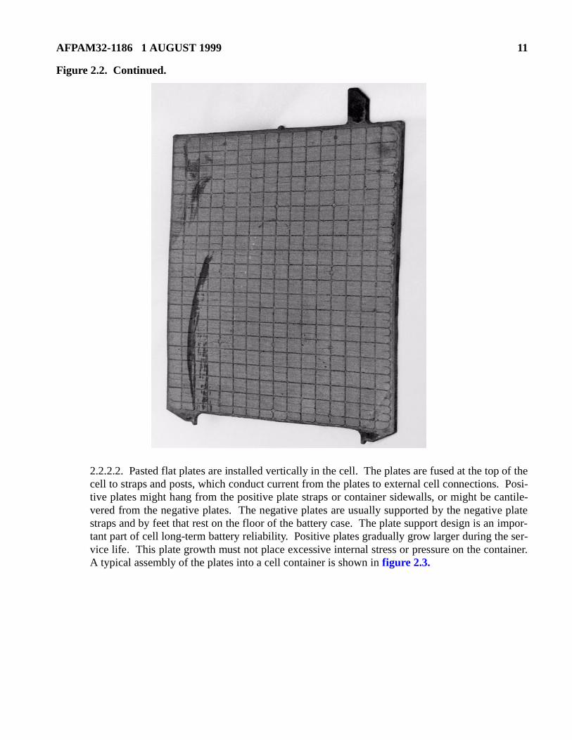
Figure 2.2. Continued.
2.2.2.2. Pasted flat plates are installed vertically in the cell. The plates are fused at the top of thecell to straps and posts, which conduct current from the plates to external cell connections. Posi-tive plates might hang from the positive plate straps or container sidewalls, or might be cantile-vered from the negative plates. The negative plates are usually supported by the negative platestraps and by feet that rest on the floor of the battery case. The plate support design is an impor-tant part of cell long-term battery reliability. Positive plates gradually grow larger during the ser-vice life. This plate growth must not place excessive internal stress or pressure on the container.A typical assembly of the plates into a cell container is shown in figure 2.3.
12 AFPAM32-1186 1 AUGUST 1999
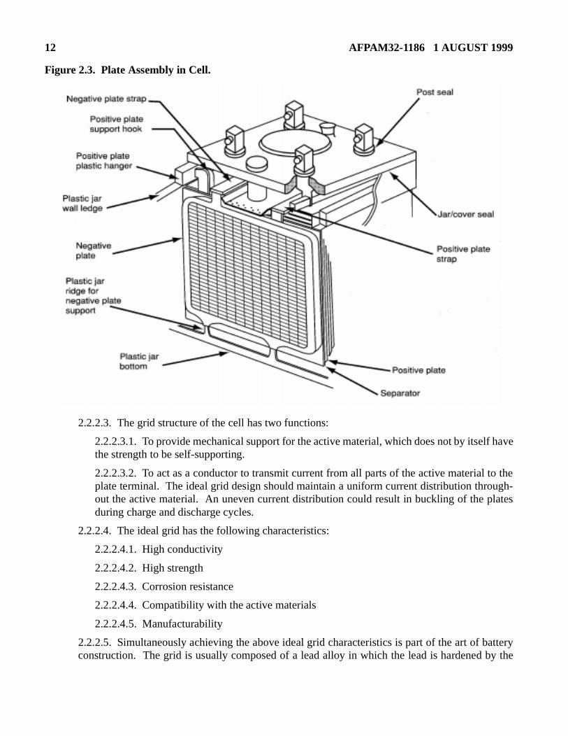
Figure 2.3. Plate Assembly in Cell.
2.2.2.3. The grid structure of the cell has two functions:
2.2.2.3.1. To provide mechanical support for the active material, which does not by itself havethe strength to be self-supporting.
2.2.2.3.2. To act as a conductor to transmit current from all parts of the active material to theplate terminal. The ideal grid design should maintain a uniform current distribution through-out the active material. An uneven current distribution could result in buckling of the platesduring charge and discharge cycles.
2.2.2.4. The ideal grid has the following characteristics:
2.2.2.4.1. High conductivity
2.2.2.4.2. High strength
2.2.2.4.3. Corrosion resistance
2.2.2.4.4. Compatibility with the active materials
2.2.2.4.5. Manufacturability
2.2.2.5. Simultaneously achieving the above ideal grid characteristics is part of the art of batteryconstruction. The grid is usually composed of a lead alloy in which the lead is hardened by the
AFPAM32-1186 1 AUGUST 1999 13
alloy so that the grid can support the plate assembly. Lead calcium-based grids are commonlyused for VRLA cell designs. Other materials might also be added to the basic lead calcium designto improve operational or manufacturing performance. For example, tin (0.3% to 0.6%) has beenadded to some lead calcium grids to:
2.2.2.5.1. Increase the grid alloy tensile strength.
2.2.2.5.2. Improve the ease of handling during manufacturing.
2.2.2.5.3. Inhibit passivation (a high resistance boundary) between the grid and active mate-rial on the positive plate.
2.2.2.6. Stationary batteries normally have n positive plates and n+1 negative plates. In thisdesign, negative plates are on both sides of each positive plate to ensure that the positive platechemical reaction is balanced. Otherwise, the more age-sensitive positive plate could expandabnormally or buckle because of an uneven chemical reaction rate.
2.2.3. Electrolyte:
2.2.3.1. The electrolyte in a lead-acid battery is a mixture of sulfuric acid and water. Specificgravity is a measure of the density of a liquid. The specific gravity of the electrolyte indicates theamount of sulfuric acid in the cell. Pure water has a specific gravity of 1.0 and the specific gravityof other liquids is usually expressed in relation to that of water. The lead-acid cell electrolyte spe-cific gravity typically varies from 1.210 to 1.300, depending on the particular cell design. Mostvented stationary cells have a specific gravity between 1.210 to 1.240. VRLA batteries commonlyuse electrolyte with a higher specific gravity (typically between 1.250 to 1.300) to compensate fora smaller quantity of electrolyte in the cell.
2.2.4. Separators:
2.2.4.1. Separators are installed between the plates to prevent the plates from touching and short-ing. A separator is constructed of a porous, nonconductive, inert material that allows conductionof electrolyte ions between the plates.
2.2.5. Container Construction:
2.2.5.1. The battery components are enclosed in a plastic jar that functions as a leak proof con-tainer for the electrolyte. The top cover is bonded to the jar and a flame arrestor vent is installedon the cover to allow charge gases to escape.
2.2.5.2. The positive and negative cell terminals are usually designed for bolted connections andare often constructed of alloyed lead. Some batteries contain copper reinforcement inserts toimprove conductivity and optimize high discharge rate performance. Copper inserts are typicallyused on the larger cells.
2.2.5.3. Jar-to-cover and terminal post seals are critical features of a cell design. A poor seal cancontribute to the following problems:
2.2.5.3.1. Acid creepage up the post causing increased corrosion
2.2.5.3.2. Acid creepage up the post causing increased connection resistance, which can affectcapacity or, in severe cases, result in post meltdown during discharge
2.2.5.3.3. Cell gases venting without the protection of a flame arrestor
14 AFPAM32-1186 1 AUGUST 1999
inter-tweenecific
atteryndencyatteryined by com-
higher design
arge is dis-h time end ofmical
2.2.5.3.4. Electrical faults which can lead to fire or electrical shocks
2.2.5.3.5. Air in-leakage to a VRLA cell that can lead to self-discharge
2.3. Electrical Characteristics:
2.3.1. Voltage:
2.3.1.1. A fully charged lead-acid cell has an open circuit voltage (OCV) of approximately 2.05 Vto 2.15 V; the exact voltage varies with the electrolyte specific gravity and temperature. The OCVincreases as the specific gravity increases, and decreases as the temperature decreases. The OCVvaries with electrolyte specific gravity by the following relationship:
OCV = Specific gravity + 0.845
2.3.1.2. For example, the OCV of a cell with an electrolyte specific gravity of 1.215 is 2.06 V(1.215 + 0.845 = 2.06). The OCV of a cell with an electrolyte specific gravity of 1.300 is 2.15 V(1.300 + 0.845 = 2.15).
2.3.1.3. The charging float voltage must be greater than the cell OCV to overcome the cell’snal resistance and allow charging current to flow through the cell. The actual difference bethe cell OCV and the desired charging float voltage is a function of the grid alloy type, spgravity, and temperature, but is usually in the range of 0.10 to 0.20 V at 25°C (77°F).
2.3.1.4. When a lead-acid battery is at full capacity, receiving a trickle charge from the bcharger, it is said to be on a float charge. A float charge overcomes the battery’s natural teto self-discharge, thereby keeping it fully charged. The float voltage for a lead-acid bdepends on the individual cell design and temperature. The optimal float voltage is determthe manufacturer. An equalizing charge is intended to recharge the battery quickly and topletely restore the active materials in the plates. An equalizing charge is performed at avoltage than a float charge; the recommended equalize voltage value varies with the batteryand electrolyte specific gravity.
2.3.2. Discharge Characteristics:
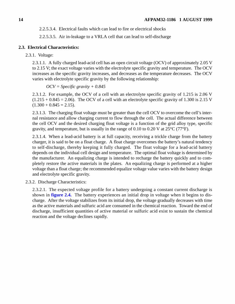
2.3.2.1. The expected voltage profile for a battery undergoing a constant current dischshown in figure 2.4. The battery experiences an initial drop in voltage when it begins tocharge. After the voltage stabilizes from its initial drop, the voltage gradually decreases witas the active materials and sulfuric acid are consumed in the chemical reaction. Toward thedischarge, insufficient quantities of active material or sulfuric acid exist to sustain the chereaction and the voltage declines rapidly.
AFPAM32-1186 1 AUGUST 1999 15
Figure 2.4. Typical Cell Voltage Profile During Constant Current Discharge.
2.3.2.2. A battery is often considered to be discharged when its voltage reaches 1.75 VPC duringa discharge at its rated capacity. However, the system design could require a higher voltage (orallow a lower voltage) to meet the voltage requirements of all components. For some high-ratedischarge applications, the battery manufacturer might provide discharge ratings for end voltagesas low as 1.5 VPC. Manufacturers rarely provide discharge ratings below 1.5 VPC; once voltagehas fallen this low, the rate of voltage decline is very rapid and little additional energy can beremoved from the battery at that discharge rate.
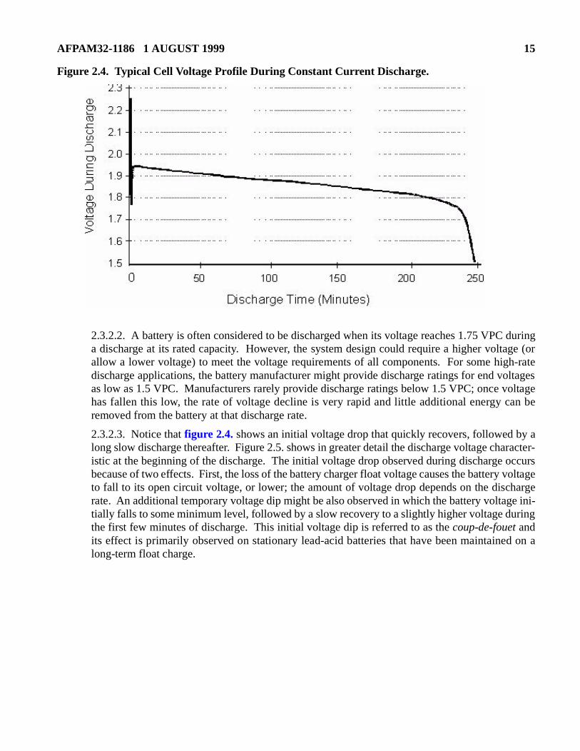
2.3.2.3. Notice that figure 2.4. shows an initial voltage drop that quickly recovers, followed by along slow discharge thereafter. Figure 2.5. shows in greater detail the discharge voltage character-istic at the beginning of the discharge. The initial voltage drop observed during discharge occursbecause of two effects. First, the loss of the battery charger float voltage causes the battery voltageto fall to its open circuit voltage, or lower; the amount of voltage drop depends on the dischargerate. An additional temporary voltage dip might be also observed in which the battery voltage ini-tially falls to some minimum level, followed by a slow recovery to a slightly higher voltage duringthe first few minutes of discharge. This initial voltage dip is referred to as the coup-de-fouet andits effect is primarily observed on stationary lead-acid batteries that have been maintained on along-term float charge.
16 AFPAM32-1186 1 AUGUST 1999
Figure 2.5. Typical Voltage Dip at Beginning of Discharge.
2.3.2.4. The coup-de-fouet primarily occurs with batteries on long term float for the followingreason. The float charge process maintains the positive plates in a nearly fully charged condition,in which the active material is all lead dioxide, PbO2, with very little lead sulfate, PbSO4, presentunder ideal conditions. During discharge, lead dioxide is converted to lead sulfate. However, thechemical reaction is better facilitated when a lead dioxide molecule is located adjacent to a leadsulfate molecule. In other words, the chemical reaction process improves in efficiency as lead sul-fate sites are generated. During the initial moments of discharge, the chemical reaction is slightlyless efficient, with the result that the voltage can dip to a lower than expected value and slowlyrecover from this voltage dip during the first few minutes of discharge as these lead sulfate sitesare created.
2.3.2.5. The coup-de-fouet effect is described here because it can limit the high-rate dischargecapability of a particular cell design. Some users have been caught by surprise during the firstminute of a high-rate discharge. In the 1980s, some UPS users experienced a high rate dischargeon their system in which battery voltage would fall below the low-voltage cutout of the UPS dur-ing the first minute of discharge. After resetting the low-voltage cutout, the UPS would performnormally without again actuating its low-voltage cutout. After further investigation, it was dis-covered that the coup-de-fouet dip during the first discharge had fallen low enough to trip thelow-voltage cutout. But, in so doing, enough lead sulfate sites had been established that the sub-sequent battery discharge at the same rate would not experience as low of a dip. Some batterymanufacturers were forced to derate their cell ratings to account for this effect.
2.3.2.6. In summary, the ideal long duration discharge has the following discharge characteristics:
2.3.2.6.1. An initial prompt voltage drop, followed by
2.3.2.6.2. A modest recovery in voltage during the first few minutes of discharge, followed by
AFPAM32-1186 1 AUGUST 1999 17
ours that is due to
The plates.
rface ofs to the
ce dur-
r wattse. A
e showsd of 250 2,000acity =
g dis-at 25°Ce cell
he cell
on, bat-id bat-lerates
refer-
2.3.2.6.3. A gradual and almost linear voltage drop during most of the discharge period, and
2.3.2.6.4. A rapid nonlinear voltage drop at the end of discharge
2.3.3. Capacity:
2.3.3.1. The rate (amperes or power) at which a lead-acid battery is discharged directly affects theampere-hours that the battery can deliver—as the discharge rate increases, the ampere-hcan be realized from the battery decreases. Decreased capacity at higher discharge ratesthe following effects:
2.3.3.1.1. Less time is available for diffusion of electrolyte into the porous lead plates.higher the discharge rate, the more the chemical reaction is limited to the surface of the
2.3.3.1.2. The discharge chemical reaction process forms larger lead sulfate on the suthe plates, which tends to close pores in the plates, thereby slowing electrolyte accesremaining active material.
2.3.3.1.3. Voltage loss occurs more quickly because of increased cell internal resistaning discharge.
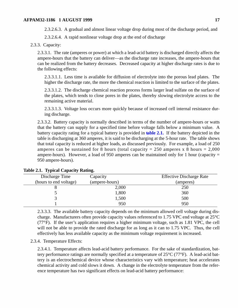
2.3.3.2. Battery capacity is normally described in terms of the number of ampere-hours othat the battery can supply for a specified time before voltage falls below a minimum valubattery capacity rating for a typical battery is provided in table 2.1. If the battery depicted in thetable is discharging at 360 amperes, it is said to be discharging at the 5-hour rate. The tablthat total capacity is reduced at higher loads, as discussed previously. For example, a loaamperes can be sustained for 8 hours (total capacity = 250 amperes x 8 hours =ampere-hours). However, a load of 950 amperes can be maintained only for 1 hour (cap950 ampere-hours).
Table 2.1. Typical Capacity Rating.
2.3.3.3. The available battery capacity depends on the minimum allowed cell voltage durincharge. Manufacturers often provide capacity values referenced to 1.75 VPC end voltage (77°F). If the user’s application requires a higher minimum voltage, such as 1.81 VPC, thwill not be able to provide the rated discharge for as long as it can to 1.75 VPC. Thus, teffectively has less available capacity as the minimum voltage requirement is increased.
2.3.4. Temperature Effects:
2.3.4.1. Temperature affects lead-acid battery performance. For the sake of standardizatitery performance ratings are normally specified at a temperature of 25°C (77°F). A lead-actery is an electrochemical device whose characteristics vary with temperature; heat accechemical activity and cold slows it down. A change in the electrolyte temperature from theence temperature has two significant effects on lead-acid battery performance:
Discharge Time(hours to end voltage)
Capacity(ampere-hours)
Effective Discharge Rate (amperes)
8 2,000 2505 1,800 3603 1,500 5001 950 950
18 AFPAM32-1186 1 AUGUST 1999
.
ity. In abilityerature
ositivee 25°Ca com-re rise
e on theire der-ecifiede life.r 25°C
d-acidique to
ffec- immo-leak
trolytectively
t excessr
main-fer-y of a
2.3.4.1.1. The battery capacity decreases as the temperature drops below 25°C (77°F)
2.3.4.1.2. The battery life decreases as the temperature rises above 25°C (77°F).
2.3.4.2. At temperatures lower than 25°C (77°F), the battery cannot provide its rated capacgeneral, a lower temperature increases the viscosity of the electrolyte, and thus restricts itsto circulate into the plates. Also, the efficiency of the chemical reaction decreases as tempdecreases.
2.3.4.3. Temperature variations have an opposite effect on battery life. The battery’s pplate corrosion rate increases exponentially as the electrolyte temperature rises abov(77°F); sustained battery operation above 25°C (77°F) shortens battery life. For example, mon rule of thumb for lead-acid batteries is that an 8.3°C (15°F) average temperatudecreases battery life by 50%.
2.3.4.4. The temperature characteristics of the battery must be evaluated at the design stagbasis of the expected temperature environment. A battery located in a cold area might requating to ensure that sufficient capacity is available to power the connected load for the spduration. A battery in a high-temperature area will fail before reaching its advertised servicRated capacity and life are simultaneously obtained only when the battery is operated nea(77°F).
2.4. Valve-Regulated Lead-Acid (VRLA) Battery Design:
2.4.1. Introduction to the VRLA Battery:
2.4.1.1. The previous sections provided technical information generally applicable to all leabatteries, including both vented and VRLA types. This section provides design features unthe VRLA battery.
2.4.1.2. The VRLA battery is an innovative design with many useful applications. It is etively sealed such that the user can not gain access to the electrolyte. And, the electrolyte isbilized so that it is not a free liquid as in a vented cell, with the result that a VRLA cell will little or no electrolyte if the container case is damaged.
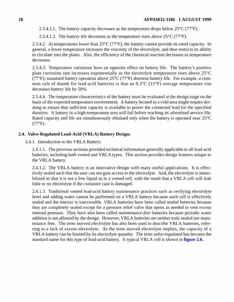
2.4.1.3. Traditional vented lead-acid battery maintenance practices such as verifying eleclevel and adding water cannot be performed on a VRLA battery because each cell is effesealed and the interior is inaccessible. VRLA batteries have been called sealed batteries becausethey are completely sealed except for a pressure relief valve that opens as needed to veninternal pressure. They have also been called maintenance-free batteries because periodic wateaddition is not allowed by the design. However, VRLA batteries are neither truly sealed nortenance free. The term starved electrolyte has also been used to describe VRLA batteries, rering to a lack of excess electrolyte. As the term starved electrolyte implies, the capacitVRLA battery can be limited by its electrolyte quantity. The term valve-regulated has become thestandard name for this type of lead-acid battery. A typical VRLA cell is shown in figure 2.6.
AFPAM32-1186 1 AUGUST 1999 19
Figure 2.6. Typical VRLA Cell.
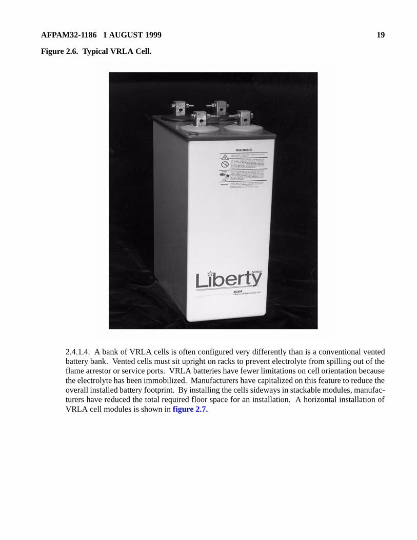
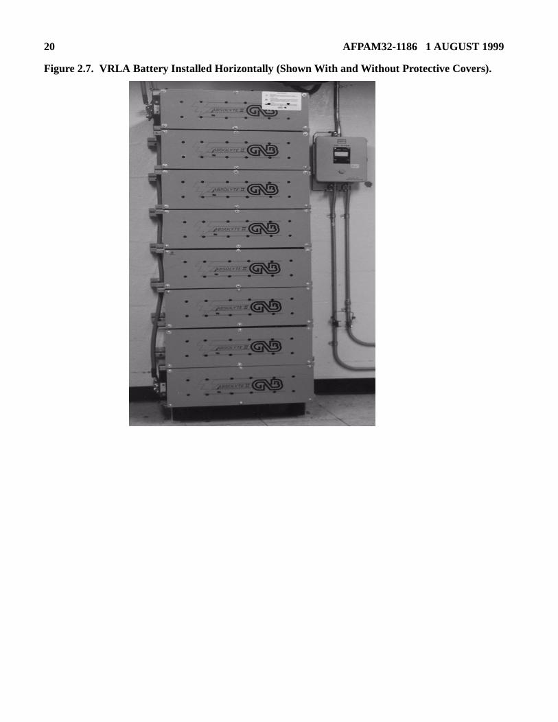
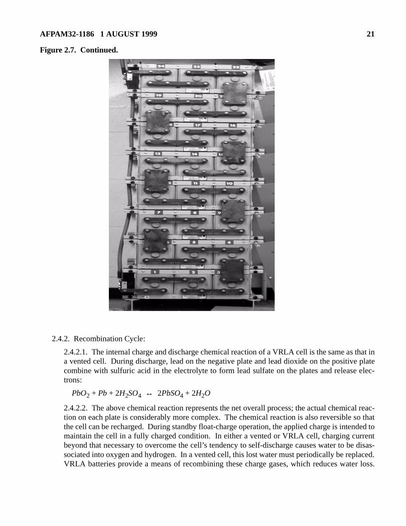
2.4.1.4. A bank of VRLA cells is often configured very differently than is a conventional ventedbattery bank. Vented cells must sit upright on racks to prevent electrolyte from spilling out of theflame arrestor or service ports. VRLA batteries have fewer limitations on cell orientation becausethe electrolyte has been immobilized. Manufacturers have capitalized on this feature to reduce theoverall installed battery footprint. By installing the cells sideways in stackable modules, manufac-turers have reduced the total required floor space for an installation. A horizontal installation ofVRLA cell modules is shown in figure 2.7.
20 AFPAM32-1186 1 AUGUST 1999
Figure 2.7. VRLA Battery Installed Horizontally (Shown With and Without Protective Covers).
AFPAM32-1186 1 AUGUST 1999 21
e disas-laced.er loss.
Figure 2.7. Continued.
2.4.2. Recombination Cycle:
2.4.2.1. The internal charge and discharge chemical reaction of a VRLA cell is the same as that ina vented cell. During discharge, lead on the negative plate and lead dioxide on the positive platecombine with sulfuric acid in the electrolyte to form lead sulfate on the plates and release elec-trons:
PbO2 + Pb + 2H2SO4 ↔ 2PbSO4 + 2H2O
2.4.2.2. The above chemical reaction represents the net overall process; the actual chemical reac-tion on each plate is considerably more complex. The chemical reaction is also reversible so thatthe cell can be recharged. During standby float-charge operation, the applied charge is intended tomaintain the cell in a fully charged condition. In either a vented or VRLA cell, charging currentbeyond that necessary to overcome the cell’s tendency to self-discharge causes water to bsociated into oxygen and hydrogen. In a vented cell, this lost water must periodically be repVRLA batteries provide a means of recombining these charge gases, which reduces wat
22 AFPAM32-1186 1 AUGUST 1999
argeegativeiency
theirnd the
tainedf cell iste sys-h rate
ay a com-l of the
voids,m the5% ofallow
itedlargerarelyt theth elec-ctro-
lectro-m- also
oughas fewwhen
Oxygen gas that evolves at the positive plate is allowed to migrate through the electrolyte to thenegative plate, where the recombination reaction occurs. In a properly operating VRLA cell, oxy-gen is generated at the positive plate, but hydrogen generation at the negative plate is suppressedby the recombination process. The primary factor in a VRLA cell’s ability to recombine chgases is its efficiency in transporting the oxygen generated at the positive plates to the nplates. When operating properly, a VRLA cell can recombine charge gases with an efficapproaching 100%.
2.4.3. VRLA Cell Construction:
2.4.3.1. Absorbed Electrolyte Construction:
2.4.3.1.1. Two VRLA cell designs are available and they are completely different in approach to immobilizing the electrolyte. The two types are the absorbed electrolyte agelled electrolyte.
2.4.3.1.2. An absorbed electrolyte design is constructed with the liquid electrolyte conin highly absorbent glass mat separators positioned between the plates. This type ocalled an absorbed glass mat (AGM) cell by some manufacturers. Absorbed electrolytems generally have a low internal resistance that allows the cell to provide a very higcurrent.
2.4.3.1.3. The mat holds the electrolyte in place by capillary action, similar to the wsponge holds water. The electrolyte is distributed throughout the mat and the mat ispressed between the plates to maintain the electrolyte in contact with the active materiaplates.
2.4.3.1.4. Achieving oxygen transport for an absorbed electrolyte cell involves creating or gas channels, in the liquid-saturated mat through which the oxygen can migrate fropositive to the negative plates. Voids exist because the mats are filled to only 90% to 9their total capacity. With 5% to 10% of a mat’s volume not filled, there are channels that oxygen migration.
2.4.3.1.5. One consequence of only partially filling the mat is that AGM cells can be limin their capacity by the quantity of sulfuric acid in the electrolyte. A vented cell has a electrolyte reserve, with the electrolyte level well above the top of the plates, and it is capacity-limited by the electrolyte. At best, an AGM cell starts with the electrolyte level atop of plates because the mat is wrapped around the plates and is not fully saturated witrolyte. This makes the AGM cell particularly susceptible to a loss of capacity if any elelyte is lost. The gradual loss of water from an AGM cell is referred to as dryout and isdescribed in detail in paragraph 3.2.1.
2.4.3.2. Gelled Electrolyte Construction:
2.4.3.2.1. The gelled electrolyte cell design is similar to a vented cell except that the elyte has been gelled to immobilize it in place. The electrolyte is combined with a silica copound to create the gelled solution. In addition to gelling the electrolyte, the silicafacilitates oxygen transport from the positive to the negative plates.
2.4.3.2.2. The primary method of oxygen transport in a gelled electrolyte cell is thrmicroscopic cracks created in the gel after a short period of operation. Initially, the gel hcracks; therefore, oxygen transport is poor and the cell recombination efficiency is low
AFPAM32-1186 1 AUGUST 1999 23
thatdoes
sorbed somes been AGM typ-
ell issity in
VRLA inter-n and
arging
rnal design
arrowent cell. Airhargeent losse cell.:
er.
.
the cell is first placed in service. This condition results in some water loss during the earlystages of operation. The water loss causes the gel to contract, forming microscopic cracks inthe gel structure. As the cracks are formed, oxygen transport is facilitated and the recombina-tion efficiency increases to a steady-state level. Water loss is minimized after the cell entersthe recombinant mode of operation. The silica added to the electrolyte also tends to increasethe rate of oxygen transport by allowing oxygen to move over the surface of the silica chains,fibers, or filaments.
2.4.3.2.3. One consequence of the gelled electrolyte design is that it vents gases during thefirst several months of operation until it finally becomes recombinant. This means it ventshydrogen just like a vented cell during its early life. Manufacturers’ literature might stateVRLA cells vent little or no hydrogen during normal operation, but the literature often not address the potential for hydrogen emission when first placed in service.
2.4.3.2.4. The gelled electrolyte cell can have a higher internal resistance than the abelectrolyte cell, and might not be as effective for high rate/short duration discharges. Inrespects, the gelled design can be thought of as a vented cell in which the liquid haimmobilized by gelling it. The gelled design has a greater electrolyte reserve than thecell and is usually better suited for long duration applications. A gelled electrolyte cell isically heavier and larger than an absorbed electrolyte cell for a given capacity.
2.4.3.2.5. The gelled electrolyte cell is not as widely used as the AGM cell. The AGM ceasier to manufacture and recycle. Also, the AGM cell usually has a higher power dena smaller footprint.
2.4.3.3. Pressure Relief Valve:
2.4.3.3.1. The VRLA cell is sealed such that the user can not add water to it. But, the is not completely sealed; its design includes a pressure relief valve to limit the maximumnal pressure of the cell, maintain a minimum internal pressure to promote recombinatiominimize water loss, and prevent atmospheric oxygen from entering the cell and dischthe negative plates.
2.4.3.3.2. Depending on the design, VRLA cells typically operate with a positive intepressure of 0.5 to 6 psig. The pressure relief valve vents any pressure exceeding thelimit.
2.4.3.3.3. The pressure relief valve must be able to open and reseal within a fairly npressure band. Although the pressure relief valve must be capable of opening to prevover-pressurization under abusive conditions, it is also critical that it recloses properly(containing oxygen) entering through an open pressure relief valve will eventually discthe negative plate by a chemical reaction with the oxygen in the air and cause a permanof capacity. Proper pressure relief valve operation is vital to continued operation of thTypical design constraints placed on the pressure relief valve by manufacturers include
2.4.3.3.3.1. Vent pressure should be low to minimize pressure bulging of the contain
2.4.3.3.3.2. Vent pressure should change very little as the gassing rate increases.
2.4.3.3.3.3. Vent outlet should be as large as possible to insure rapid venting.
2.4.3.3.3.4. Valve elastomer material should be resistant to ozone cracking and acid
24 AFPAM32-1186 1 AUGUST 1999
—the
noth-l withegativeplate
ropegativepolar-needed cell’sgative of its
rging. Forific
2.4.3.3.3.5. Under static conditions, air must not be able to enter the cell.
2.4.4. Operational Characteristics:
2.4.4.1. Electrolyte Concentration:
2.4.4.1.1. A vented lead-acid cell has a substantial electrolyte reserve and its capacity is usu-ally limited by the quantity of active material in its plates. The term starved electrolyte hasbeen used to describe VRLA batteries, typically referring to the limited quantity of electrolytein an AGM cell. Depending on the design, the capacity of a VRLA cell can be limited by itselectrolyte quantity.
2.4.4.1.2. Manufacturers have attempted to improve VRLA battery capacity by increasing theelectrolyte specific gravity of some AGM cells to as high as 1.300 (typical vented stationarybatteries have a specific gravity of 1.210 to 1.240). A higher specific gravity means that moresulfuric acid is available to participate in the chemical reaction during discharge. Increasingthe specific gravity also affects VRLA operating characteristics such as float voltage range andrated life. The gelled electrolyte design typically has a greater electrolyte reserve than theAGM design and generally does not require as high of a specific gravity to compensate forelectrolyte-limited capacity.
2.4.4.2. Electrical Characteristics:
2.4.4.2.1. The electrical characteristics described in paragraph 2.3. apply to both vented andVRLA cells. The principal electrical difference between the two types is how the float voltageis distributed across the positive and negative plates. This section explains this key differencebetween vented and VRLA cells.
2.4.4.2.2. Float voltage is applied by the charger to maintain each cell fully charged. If thefloat voltage is too low, the cells can self-discharge and slowly lose capacity. If the float volt-age is too high, the cells are overcharged, causing gassing and premature aging. Each batterytype has a particular float voltage range within which optimal performance is expectedbattery remains fully charged without significant overcharging.
2.4.4.2.3. The open circuit voltage (OCV) is the voltage across the cell terminals whening is connected to it. Part of the OCV is made up by the positive plate positive potentiarespect to the electrolyte. The remainder of the OCV is made up by the negative plate npotential with respect to the electrolyte. The total OCV is the potential of the positive with respect to the negative plate.
2.4.4.2.4. If a cell is left on open circuit, it will slowly self-discharge and the OCV will das the cell discharges. When charging current is applied to the cell, the positive and nplates polarize (develop an added potential) relative to their open circuit potential. The ization does not occur immediately because some small amount of charging current is to offset the cell’s tendency to self-discharge. As the charging current is increased, thetotal voltage rises to be the sum of the OCV, the positive plate polarization, and the neplate polarization. The total plate polarization is that potential on the plate in excessOCV potential.
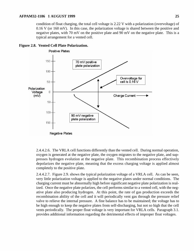
2.4.4.2.5. Figure 2.8. shows a typical example of plate polarization as a function of chacurrent. Plate polarization is typically described with respect to the OCV plate potentialthe cell shown in figure 2.8., suppose that the cell OCV is 2.06 V. As shown for the spec
AFPAM32-1186 1 AUGUST 1999 25
condition of float charging, the total cell voltage is 2.22 V with a polarization (overvoltage) of0.16 V (or 160 mV). In this case, the polarization voltage is shared between the positive andnegative plates, with 70 mV on the positive plate and 90 mV on the negative plate. This is atypical arrangement for a vented cell.
Figure 2.8. Vented Cell Plate Polarization.
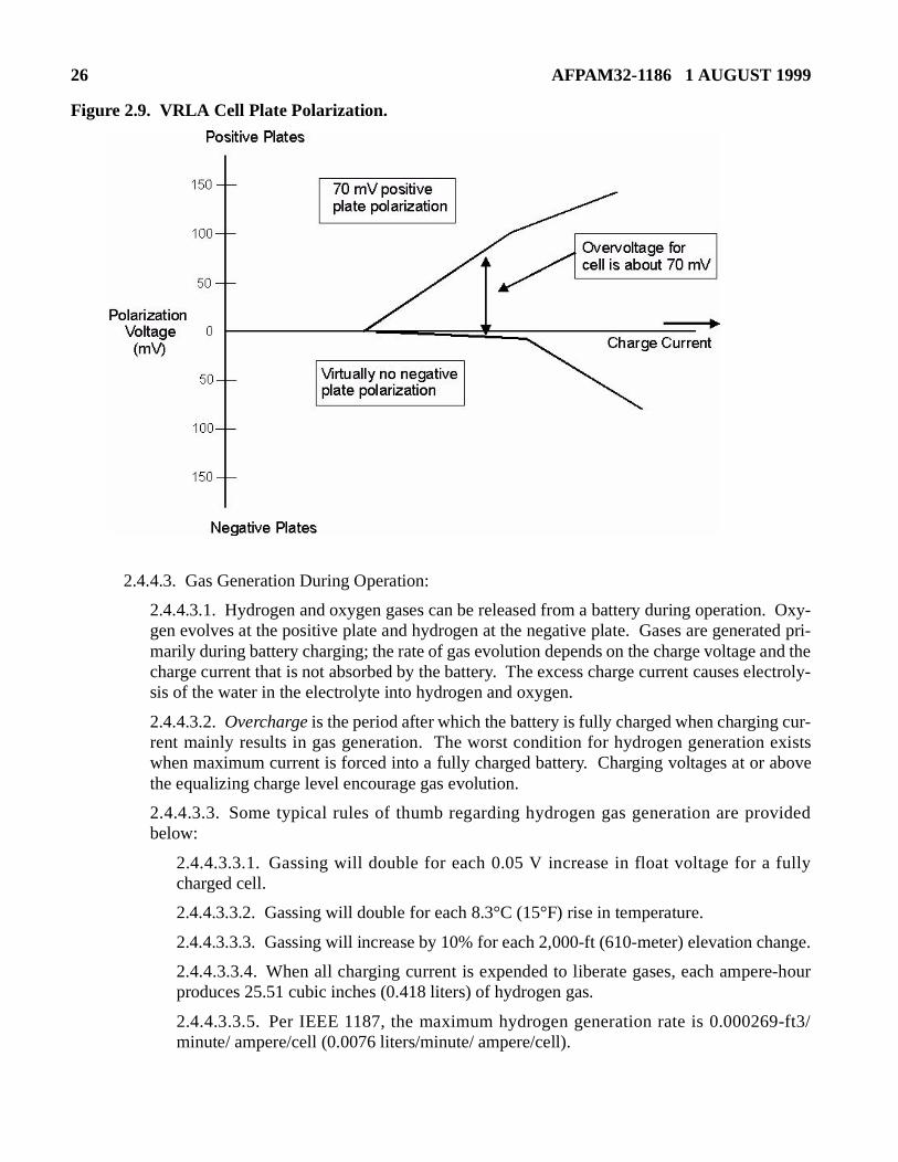
2.4.4.2.6. The VRLA cell functions differently than the vented cell. During normal operation,oxygen is generated at the negative plate, the oxygen migrates to the negative plate, and sup-presses hydrogen evolution at the negative plate. This recombination process effectivelydepolarizes the negative plate, meaning that the excess charging voltage is applied almostcompletely to the positive plate.
2.4.4.2.7. Figure 2.9. shows the typical polarization voltage of a VRLA cell. As can be seen,very little polarization voltage is applied to the negative plates under normal conditions. Thecharging current must be abnormally high before significant negative plate polarization is real-ized. Once the negative plate polarizes, the cell performs similar to a vented cell, with the neg-ative plate also producing hydrogen. At this point, the rate of gas production exceeds therecombination ability of the cell and it will periodically vent gas through the pressure reliefvalve to relieve the internal pressure. A fine balance has to be maintained; the voltage has tobe high enough to keep the negative plates from self-discharging, but not so high that the cellvents periodically. The proper float voltage is very important for VRLA cells. Paragraph 3.1.provides additional information regarding the detrimental effects of improper float voltages.
26 AFPAM32-1186 1 AUGUST 1999
ange.
re-hour
9-ft3/
Figure 2.9. VRLA Cell Plate Polarization.
2.4.4.3. Gas Generation During Operation:
2.4.4.3.1. Hydrogen and oxygen gases can be released from a battery during operation. Oxy-gen evolves at the positive plate and hydrogen at the negative plate. Gases are generated pri-marily during battery charging; the rate of gas evolution depends on the charge voltage and thecharge current that is not absorbed by the battery. The excess charge current causes electroly-sis of the water in the electrolyte into hydrogen and oxygen.
2.4.4.3.2. Overcharge is the period after which the battery is fully charged when charging cur-rent mainly results in gas generation. The worst condition for hydrogen generation existswhen maximum current is forced into a fully charged battery. Charging voltages at or abovethe equalizing charge level encourage gas evolution.
2.4.4.3.3. Some typical rules of thumb regarding hydrogen gas generation are providedbelow:
2.4.4.3.3.1. Gassing will double for each 0.05 V increase in float voltage for a fullycharged cell.
2.4.4.3.3.2. Gassing will double for each 8.3°C (15°F) rise in temperature.
2.4.4.3.3.3. Gassing will increase by 10% for each 2,000-ft (610-meter) elevation ch
2.4.4.3.3.4. When all charging current is expended to liberate gases, each ampeproduces 25.51 cubic inches (0.418 liters) of hydrogen gas.
2.4.4.3.3.5. Per IEEE 1187, the maximum hydrogen generation rate is 0.00026minute/ ampere/cell (0.0076 liters/minute/ ampere/cell).
AFPAM32-1186 1 AUGUST 1999 27
ssion” cellwhichndardsogen
y thent drift,
til its to an
en forrous
2.4.4.3.4. Some battery manufacturers’ literature markets “little or no hydrogen gas emias one more attractive design feature of the VRLA cell. Although it is true that a VRLAoperating in the recombinant mode will vent very little gas, there are conditions under the VRLA cell can vent as much hydrogen as a vented cell. For this reason, IEEE staspecify that VRLA battery installations should include adequate ventilation to avoid hydrbuildup in the area.
2.4.4.3.5. Under the following conditions, a VRLA cell will vent hydrogen:
2.4.4.3.5.1. During an equalize charge or elevated float charge.
2.4.4.3.5.2. Whenever float voltage is set significantly higher than recommended bmanufacturer regardless of the reason—deliberately set, set in error, charger setpoior charger failure.
2.4.4.3.5.3. During the first few months of operation for a gelled electrolyte cell unvents enough water to finally become recombinant. The same consideration applieAGM cell that was overfilled at the factory.
2.4.4.3.6. The system design must account for the possibility of hydrogen generation evVRLA batteries. Not accounting for hydrogen gas emission from a VRLA cell is dangeand can lead to personnel injury or equipment damage.
28 AFPAM32-1186 1 AUGUST 1999
8.3°C
atteries
corro-
harge.
ging. batter-
y life.
d dura-
Chapter 3
VRLA BATTERY AGING, DEGRADATION, AND FAILURE
3.1. Introduction:
3.1.1. VRLA batteries exhibit the same aging and degradation characteristics as vented lead-acid bat-teries. But, they have additional failures modes that are a result of the new technology. Paragraph 3.2.provides an overview of traditional aging mechanisms for vented lead-acid and VRLA batteries.Paragraph 3.3. discusses additional aging and failure mechanisms specific to VRLA batteries.
3.2. Traditional Lead-Acid Battery Aging:
3.2.1. Service Life Considerations:
3.2.1.1. The lead-acid battery is a sacrificial design, destined to eventually wear out even in idealconditions. And, when abused, it can fail even sooner. Under ideal conditions, both vented andVRLA batteries fail by natural aging due to the following causes:
3.2.1.1.1. Expansion and corrosion of the positive grid structure due to oxidation of the gridand plate materials. This degradation mechanism is unavoidable and is the most common nat-ural failure mode for lead-acid batteries maintained on a float charge.
3.2.1.1.2. .Loss of active material from the positive plate.
3.2.1.1.3. Loss of capacity due to physical changes in the active material of the positive plate.
3.2.1.2. Some vented batteries survive longer than 20 years with little loss of capability. Othersfail within a few years of service. Several factors combine to affect battery life; examples arelisted below.
3.2.1.2.1. Design life. Stationary batteries are typically available with a design life rangingfrom 5 to 20 years. Longer life batteries generally cost more.
3.2.1.2.2. Temperature. Elevated temperatures reduce battery life. An increase of(15°F) can reduce lead-acid battery life by 50% or more.
3.2.1.2.3. Cycle service. Excessive deep discharge cycles reduce life. Lead calcium bmight be rated for as few as 50 deep discharge cycles.
3.2.1.2.4. Overcharging. Excessively high float voltages cause a higher positive platesion rate. Overcharging also causes excessive gassing.
3.2.1.2.5. Undercharging. A low float voltage reduces capacity because of self-discUndercharging can also result in sulfation, which can damage the plates.
3.2.1.2.6. DC ripple current. Excessive DC ripple current might contribute to battery aVRLA batteries are considered more susceptible to ripple current than vented lead-acidies.
3.2.1.2.7. Manufacturing variations. Lot-to-lot processing variations can shorten batter
3.2.1.2.8. Improper storage. Storing wet cells beyond the manufacturer’s recommendetion promotes sulfation, and decreases cell capacity and life.
AFPAM32-1186 1 AUGUST 1999 29
n lly
reaches for arone tocharge
cussedramatic; harsh
om the
3.2.1.2.9. Misapplications. Batteries are commonly designed for a specific use. If the batteryis not designed for a given application, it might not meet its life or performance expectations.
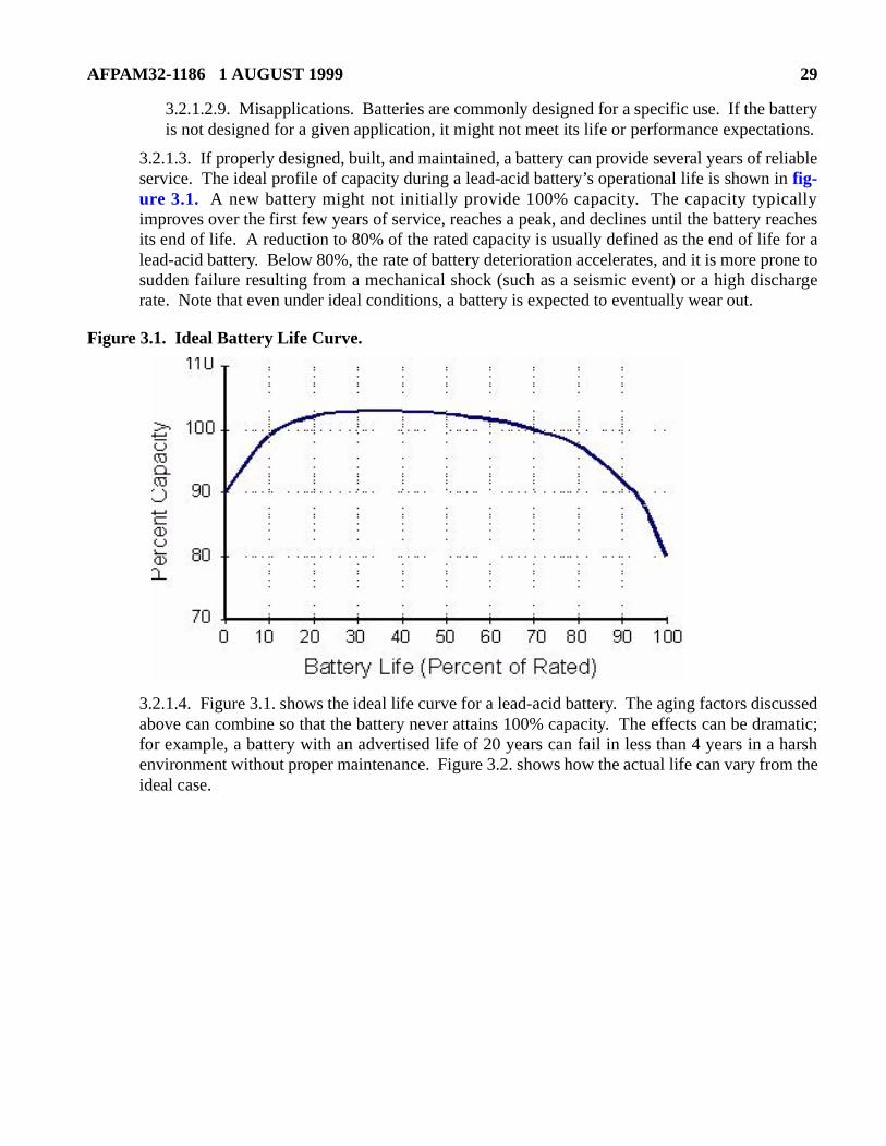
3.2.1.3. If properly designed, built, and maintained, a battery can provide several years of reliableservice. The ideal profile of capacity during a lead-acid battery’s operational life is shown ifig-ure 3.1. A new battery might not initially provide 100% capacity. The capacity typicaimproves over the first few years of service, reaches a peak, and declines until the battery its end of life. A reduction to 80% of the rated capacity is usually defined as the end of lifelead-acid battery. Below 80%, the rate of battery deterioration accelerates, and it is more psudden failure resulting from a mechanical shock (such as a seismic event) or a high disrate. Note that even under ideal conditions, a battery is expected to eventually wear out.
Figure 3.1. Ideal Battery Life Curve.
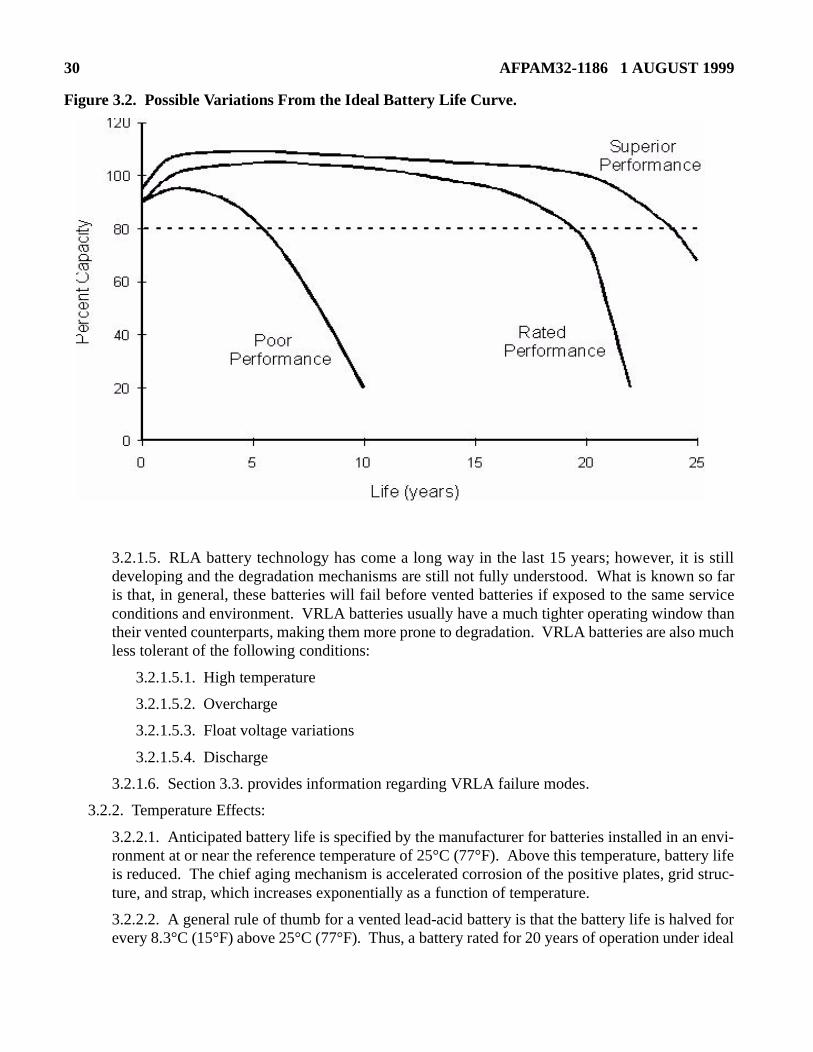
3.2.1.4. Figure 3.1. shows the ideal life curve for a lead-acid battery. The aging factors disabove can combine so that the battery never attains 100% capacity. The effects can be dfor example, a battery with an advertised life of 20 years can fail in less than 4 years in aenvironment without proper maintenance. Figure 3.2. shows how the actual life can vary frideal case.
30 AFPAM32-1186 1 AUGUST 1999
tery lifed struc-
ed forr ideal
Figure 3.2. Possible Variations From the Ideal Battery Life Curve.
3.2.1.5. RLA battery technology has come a long way in the last 15 years; however, it is stilldeveloping and the degradation mechanisms are still not fully understood. What is known so faris that, in general, these batteries will fail before vented batteries if exposed to the same serviceconditions and environment. VRLA batteries usually have a much tighter operating window thantheir vented counterparts, making them more prone to degradation. VRLA batteries are also muchless tolerant of the following conditions:
3.2.1.5.1. High temperature
3.2.1.5.2. Overcharge
3.2.1.5.3. Float voltage variations
3.2.1.5.4. Discharge
3.2.1.6. Section 3.3. provides information regarding VRLA failure modes.
3.2.2. Temperature Effects:
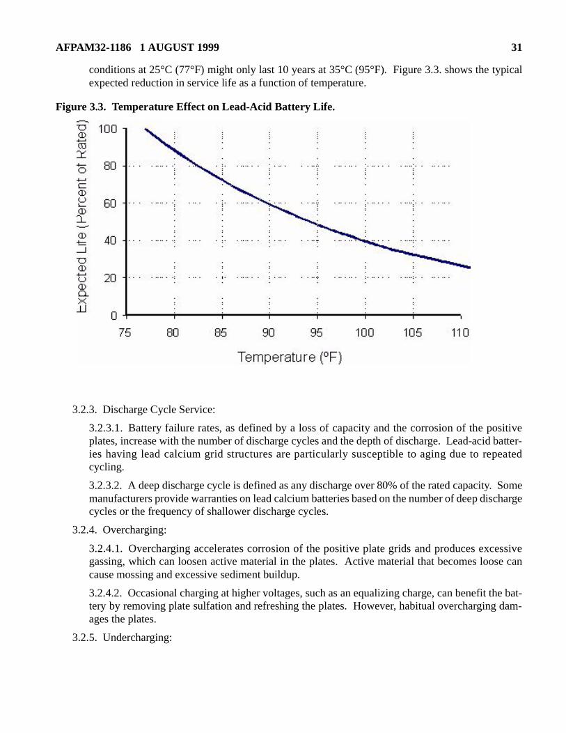
3.2.2.1. Anticipated battery life is specified by the manufacturer for batteries installed in an envi-ronment at or near the reference temperature of 25°C (77°F). Above this temperature, batis reduced. The chief aging mechanism is accelerated corrosion of the positive plates, griture, and strap, which increases exponentially as a function of temperature.
3.2.2.2. A general rule of thumb for a vented lead-acid battery is that the battery life is halvevery 8.3°C (15°F) above 25°C (77°F). Thus, a battery rated for 20 years of operation unde
AFPAM32-1186 1 AUGUST 1999 31
ypical
ositive batter-eated
. Someischarge
cessivese can
the bat- dam-
conditions at 25°C (77°F) might only last 10 years at 35°C (95°F). Figure 3.3. shows the texpected reduction in service life as a function of temperature.
Figure 3.3. Temperature Effect on Lead-Acid Battery Life.
3.2.3. Discharge Cycle Service:
3.2.3.1. Battery failure rates, as defined by a loss of capacity and the corrosion of the pplates, increase with the number of discharge cycles and the depth of discharge. Lead-acidies having lead calcium grid structures are particularly susceptible to aging due to repcycling.
3.2.3.2. A deep discharge cycle is defined as any discharge over 80% of the rated capacitymanufacturers provide warranties on lead calcium batteries based on the number of deep dcycles or the frequency of shallower discharge cycles.
3.2.4. Overcharging:
3.2.4.1. Overcharging accelerates corrosion of the positive plate grids and produces exgassing, which can loosen active material in the plates. Active material that becomes loocause mossing and excessive sediment buildup.
3.2.4.2. Occasional charging at higher voltages, such as an equalizing charge, can benefittery by removing plate sulfation and refreshing the plates. However, habitual overchargingages the plates.
3.2.5. Undercharging:
32 AFPAM32-1186 1 AUGUST 1999
is not
osesed by
te canre lostt nor- a 20%
inationtil itffects
of thethe vol-duringuch as
as vent-
3.2.5.1. Batteries lose capacity because of self-discharge if they are consistently undercharged.An undercharge condition is indicated by a low specific gravity, low cell voltage, or lighter coloron the plates. An undercharged battery might not be at full capacity and can become permanentlydamaged from sulfation.
3.2.5.2. Chronic undercharging results in a harmful buildup of lead sulfate on the plates, calledsulfation. Lead sulfate formed as a result of undercharging is inherently different in structure fromlead sulfate formed during normal cell discharge. The lead sulfate formed during normal dis-charge has a very fine crystalline structure that is easily broken down by charging current. Thelead sulfate crystals formed as a result of undercharging continue to grow and eventually reach asize that cannot be easily broken down by charge current. Additionally, the lead sulfate crystalsphysically occupy more space than the original active material. An excessive buildup of lead sul-fate can make the plates warp or buckle.
3.2.6. Overdischarge:
3.2.6.1. Hydration occurs in a lead-acid battery that is overdischarged and not promptlyrecharged, or a battery that remains in a discharged condition for an extended time (such as mightoccur during long-term storage). Hydration results when the lead and lead compounds of theplates dissolve in the water of a discharged cell and form lead hydrate, which is deposited on theseparators. When the cell is recharged, multiple internal short circuits occur between the positiveand negative plates.
3.2.6.2. Once hydration is evident, the cell is permanently damaged. Hydration is visible in trans-parent vented cells as a white “bathtub ring” approximately halfway up the jar. Hydration visible in VRLA cells because the containers are opaque.
3.3. VRLA Battery Failure Modes:
3.3.1. Dryout:
3.3.1.1. Loss of water from a VRLA cell is irreversible in most designs. As a VRLA cell lwater, it can experience loss of capacity due to dryout. Water addition is not normally allowthe VRLA design. These batteries have been referred to as starved electrolyte, meaning that thedischarge capacity can be limited by the electrolyte. In this case, any loss of electrolyadversely affect capacity. A vented battery is expected to require periodic watering to restowater; however, any water loss from a VRLA battery is irreversible because water cannomally be added to the cell. One study determined that a 10% water loss could correlate toloss of capacity. Any water loss from a VRLA cell is cause for concern.
3.3.1.2. The recombination process tends to be somewhat self-regulating in that recombefficiency tends to improve as water is lost. In theory, a VRLA cell would lose water unreached optimal recombination efficiency, with little water loss thereafter. However, other ethat occur during normal and abnormal operation also cause water loss:
3.3.1.2.1. Overcharging. This results in gassing that exceeds the recombination abilitybattery. Thus, gases are vented from the battery through the pressure relief valve and ume of the electrolyte solution declines over time. Small amounts of gas are vented normal float operation. Larger gas quantities are vented during higher charging rates, san equalize charge. Battery charger setpoint drift or failure can also cause increased ging.
AFPAM32-1186 1 AUGUST 1999 33
ational of the
mpera-
s thewed to
s, the varieshumid- water
lure of
kage—ocessakage
harge of
e at ancurrent.arged energytion is thermalired to insidempera-al run-
3.3.1.2.2. Corrosion process. The grid corrosion process that occurs during normal aging of alead-acid battery consumes part of the water in the electrolyte throughout the cell’s operlife. One study showed that this normal aging process alone could consume enoughelectrolyte water to limit capacity.
3.3.1.2.3. High temperature. The gassing rate increases with temperature. At high teture, some gases are vented rather than recombined inside the cell.
3.3.1.2.4. Failure of the pressure relief valve. A failure of the valve to fully shut causebattery to operate like a vented cell; it continuously vents. Charge gases are then alloescape and the recombination process is ineffective.
3.3.1.2.5. Water vapor diffusion through the container. As the temperature increasewater vapor diffusion rate through the cell container also increases. The diffusion ratewith the type and thickness of container materials, operating temperature, and relative ity around the cell. Most manufacturers have selected container materials that minimizevapor diffusion.
3.3.1.2.6. Leakage. A cracked battery case or failed terminal post seal is similar to faithe pressure relief valve; the cell can continuously vent.
3.3.1.3. Two of the above causes of dryout—pressure relief valve failure and container leaactually represent another potential failure mode for a VRLA battery. The recombination prcauses the negative plate to be maintained in an almost depolarized condition. Air in-lethrough a pressure relief valve, post seal leak, or container crack can cause eventual discthe negative plate. The cell will lose capacity as the negative plate discharges.
3.3.2. Thermal Runaway:
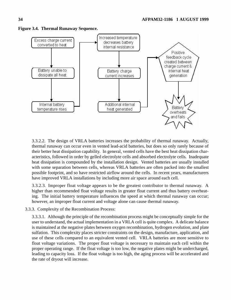
3.3.2.1. Thermal runaway is a failure mode in which a battery on a constant voltage chargelevated temperature destroys itself through internal heat generation due to high internal Under normal operating conditions, a VRLA battery on a float charge remains in a fully chcondition and most gases that are produced are recombined internally. Any overchargeresults in heat generation. If the design of the battery in conjunction with its installed locasuch that the generated heat can be dissipated without a rise in the battery temperature,runaway is unlikely. However, if the battery temperature increases, higher current is requkeep the float voltage at the set level. The additional current results in more gas generationthe cell, which generates more heat during recombination and further raises the battery teture. If the situation is not corrected, the battery can overheat and destroy itself. The thermaway sequence is shown in figure 3.4.
34 AFPAM32-1186 1 AUGUST 1999
Figure 3.4. Thermal Runaway Sequence.
3.3.2.2. The design of VRLA batteries increases the probability of thermal runaway. Actually,thermal runaway can occur even in vented lead-acid batteries, but does so only rarely because oftheir better heat dissipation capability. In general, vented cells have the best heat dissipation char-acteristics, followed in order by gelled electrolyte cells and absorbed electrolyte cells. Inadequateheat dissipation is compounded by the installation design. Vented batteries are usually installedwith some separation between cells, whereas VRLA batteries are often packed into the smallestpossible footprint, and so have restricted airflow around the cells. In recent years, manufacturershave improved VRLA installations by including more air space around each cell.
3.3.2.3. Improper float voltage appears to be the greatest contributor to thermal runaway. Ahigher than recommended float voltage results in greater float current and thus battery overheat-ing. The initial battery temperature influences the speed at which thermal runaway can occur;however, an improper float current and voltage alone can cause thermal runaway.
3.3.3. Complexity of the Recombination Process:
3.3.3.1. Although the principle of the recombination process might be conceptually simple for theuser to understand, the actual implementation in a VRLA cell is quite complex. A delicate balanceis maintained at the negative plates between oxygen recombination, hydrogen evolution, and platesulfation. This complexity places stricter constraints on the design, manufacture, application, anduse of these cells compared to an equivalent vented cell. VRLA batteries are more sensitive tofloat voltage variations. The proper float voltage is necessary to maintain each cell within theproper operating range. If the float voltage is too low, the negative plates might be undercharged,leading to capacity loss. If the float voltage is too high, the aging process will be accelerated andthe rate of dryout will increase.
AFPAM32-1186 1 AUGUST 1999 35
turer’s mV 6 mV
ging att allows VRLAy. Inrovidedte at ancreasepera-
ished.ity. In
lyte spe-40).ecific
rrosion
r timeeen thentact withsing the
can berticular,
3.3.3.2. Figure 2.9. shows the typical polarization voltage of a VRLA cell. As can be seen, verylittle polarization voltage is applied to the negative plates under normal conditions. The chargingcurrent must be abnormally high before significant negative plate polarization is realized. Thislow level of polarization means that the negative plates can experience a loss of capacity over timeby partially discharging if the level of polarization is inadequate to prevent self-discharge.
3.3.3.3. .If the charging voltage is too high, the negative plate polarizes and the cell performs sim-ilar to a vented cell, with the negative plate also producing hydrogen. At this point, the rate of gasproduction exceeds the recombination ability of the cell and it will periodically vent gas throughthe pressure relief valve to relieve the internal pressure.
3.3.3.4. If the float voltage (and float current) is too high, the life of a VRLA cell will also bereduced, partly because of accelerated aging of the positive plate by the higher float current andpartly because of the increased rate of internal dryout by more frequent gas venting. For this rea-son, the manufacturer typically specifies a maximum allowable float voltage and some manufac-turers set limits on the frequency and duration of periodic equalizing charges. One manufacoperating manual predicts a 50% reduction in battery life if float voltage is continuously 2above the specified range, and a 75% reduction in battery life if float voltage is continuouslyabove the specified range.
3.3.4. Temperature Effects:
3.3.4.1. VRLA batteries tend to be more susceptible to degradation and accelerated ahigher temperatures than are vented lead-acid batteries. The recombination process thathese batteries to operate without the need for water addition also releases heat. Olderinstallations tend to have the cells tightly packed, further limiting heat dissipation capabilitUPS applications, these batteries are often enclosed inside a cabinet with little allowance pfor heat dissipation. All of these factors can combine to cause the battery to operahigher-than-ambient temperature, thereby decreasing its life. Higher temperatures also ithe rate of dryout and increase the susceptibility to thermal runaway. Abnormally high temtures can cause a VRLA cell to fail completely.
3.3.5. Electrolyte Concentration:
3.3.5.1. The electrolyte in VRLA cells is a limited resource that can not normally be replenAny loss of electrolyte during normal and abnormal operating conditions can reduce capacsome cases, manufacturers have attempted to improve capacity by increasing the electrocific gravity up to 1.300 (typical vented batteries have a specific gravity of 1.215 to 1.2Increasing the specific gravity increases capacity at the expense of cell life. A higher spgravity results in increased chemical activity, thereby causing an increased positive plate corate.
3.3.6. Absorbed Glass Mat Compression Effects:
3.3.6.1. VRLA batteries of the AGM design can experience changes in the mat position overesulting in loss of compression between the mat and the plates. Compression betwabsorbed glass mat and the plates is necessary to ensure that the plates are in constant cothe electrolyte. Over time, small voids can develop between the mat and the plates, increainternal resistance and decreasing the available capacity. This effect is referred to as loss of com-pression and causes a permanent loss of capacity in an AGM cell. This loss of compressioncaused by manufacturing errors, improper design or design tolerances, and dryout. In pa
36 AFPAM32-1186 1 AUGUST 1999
ode andlyte; plates.mbina-re and
ive strapss mat
m aariousccord-litydic dis-
a very dis-omly
apacitybatteryo otherinationr cells
t limita-
lls are
mper-
for sta-
ievablen theot bebecaused with
the design and manufacturing process have been important contributors to loss of compressionbecause battery manufacturers did not fully appreciate the importance of compression on the per-formance of a cell. Dryout is an inevitable aging effect that also changes the level of compressionover a cell’s service life.
3.3.7. Negative Strap Corrosion:
3.3.7.1. .Some VRLA batteries have shown a tendency for the negative plate straps to corrfail prematurely. In an AGM VRLA cell, the negative strap is not immersed in the electroinstead, it is exposed to a nearly pure hydrogen environment in the void space above theWith the negative strap exposed and the negative plates normally depolarized by the recotion process, the negative strap can experience sulfation that ultimately leads to its fractufailure. Some manufacturers have redesigned their batteries to be more resistant to negatcorrosion. Design changes have included wrapping the negative strap with absorbed glamaterial to help keep it wetted or more carefully matching the grip, strap, and post alloys.
3.3.8. VRLA Failure Characteristics:
3.3.8.1. Although it is a type of lead-acid battery, the VRLA battery is distinctly different frovented lead-acid battery with regard to how it ages, degrades, and ultimately fails. The vfailure modes described in the previous sections readily demonstrate these differences. Aingly, VRLA cell failures tend to show up differently than do vented cell failures. A high-quavented lead-acid battery tends to have its cells age at about the same rate. When periocharge tests are performed, it is not uncommon to find that all of the vented cells perform insimilar manner during discharge. VRLA cells tend to exhibit a different behavior duringcharge. Although many of the cells might perform quite well, some of the cells often randfail, with rapid voltage decline during discharge.
3.3.8.2. What this means for those users that perform periodic discharge tests is that a ctest becomes more of a tool to find bad cells rather than a trending tool to determine overall capacity. Failed cells obviously require replacement; however, cell replacement can lead tproblems also. Refer to the previous discussion regarding the complexity of the recombprocess; new replacement cells will usually have different float characteristics than the oldealready in service. Some battery manufacturers’ literature attempts to address this inherention of float charge behavior with the following recommendations:
3.3.8.2.1. Minimize the number of cells in series to reduce the likelihood that some ceundercharged while other cells are overcharged.
3.3.8.2.2. Use cells of the same age and type in each string.
3.3.8.2.3. Avoid installing the battery near hot spots (or any location that can cause a teature differential across the battery).
3.3.8.2.4. If necessary, break up the string into smaller charging groups (seldom done tionary applications).
3.3.8.3. Although the above recommendations are well intended, they are not always achin the field. For example, replacement cells for failed cells will be of a different age tharemaining already installed cells. This will contribute to float voltage variations, but cannavoided because replacement cells are required. Usually, replacing the entire battery just a few cells failed is not acceptable from a budget perspective. As more cells are replace
AFPAM32-1186 1 AUGUST 1999 37
ltage of
ing toienceranty
ilure 7 yearsed thata range
apaci-r 5 to 8t 110 Vity bat-te thane.
ardingGMpected
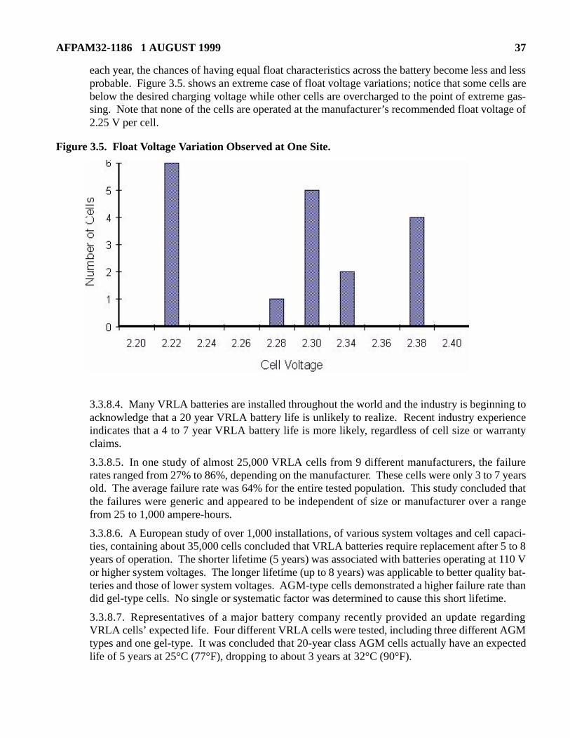
each year, the chances of having equal float characteristics across the battery become less and lessprobable. Figure 3.5. shows an extreme case of float voltage variations; notice that some cells arebelow the desired charging voltage while other cells are overcharged to the point of extreme gas-sing. Note that none of the cells are operated at the manufacturer’s recommended float vo2.25 V per cell.
Figure 3.5. Float Voltage Variation Observed at One Site.
3.3.8.4. Many VRLA batteries are installed throughout the world and the industry is beginnacknowledge that a 20 year VRLA battery life is unlikely to realize. Recent industry experindicates that a 4 to 7 year VRLA battery life is more likely, regardless of cell size or warclaims.
3.3.8.5. In one study of almost 25,000 VRLA cells from 9 different manufacturers, the farates ranged from 27% to 86%, depending on the manufacturer. These cells were only 3 toold. The average failure rate was 64% for the entire tested population. This study concludthe failures were generic and appeared to be independent of size or manufacturer over from 25 to 1,000 ampere-hours.
3.3.8.6. A European study of over 1,000 installations, of various system voltages and cell cties, containing about 35,000 cells concluded that VRLA batteries require replacement afteyears of operation. The shorter lifetime (5 years) was associated with batteries operating aor higher system voltages. The longer lifetime (up to 8 years) was applicable to better qualteries and those of lower system voltages. AGM-type cells demonstrated a higher failure radid gel-type cells. No single or systematic factor was determined to cause this short lifetim
3.3.8.7. Representatives of a major battery company recently provided an update regVRLA cells’ expected life. Four different VRLA cells were tested, including three different Atypes and one gel-type. It was concluded that 20-year class AGM cells actually have an exlife of 5 years at 25°C (77°F), dropping to about 3 years at 32°C (90°F).

38 AFPAM32-1186 1 AUGUST 1999
3.3.8.8. In summary, VRLA batteries can have a shorter-than-advertised life and some manufac-turers have acknowledged this limitation. With each generation, VRLA batteries will likely con-tinue to improve. However, their greatest strengths that make them so popular for use are alsotheir greatest weaknesses in terms of the user’s ability to identify cell failures.
AFPAM32-1186 1 AUGUST 1999 39
Chapter 4 INDUSTRY STANDARDS APPLICABLE TO VRLA BATTERIES
4.1. Introduction:
4.1.1. The Institute of Electrical and Electronic Engineers (IEEE) provides comprehensive guidancefor stationary batteries. IEEE has issued three standards to address the particular needs of VRLA bat-teries, including application, selection, installation, maintenance, and testing. Each standard isdescribed in the following sections. The purpose of discussing these standards is to provide an over-view of the type of inspection, testing, and maintenance that has been recommended by industryexperts. The issues addressed by these IEEE standards have been considered in the development ofthis manual.
4.2. IEEE 1187-1996:
4.2.1. IEEE 1187-1996, IEEE Recommended Practice for Installation Design and Installation ofValve-Regulated Lead Acid Storage Batteries for Stationary Applications, provides recommendationsfor the design and initial installation of a VRLA battery. The following topics are addressed by thisrecommended practice:
4.2.1.1. Safety precautions and procedures
4.2.1.2. Battery location
4.2.1.3. Receiving and storage
4.2.1.4. Cell mounting and connections
4.2.1.5. Freshening/initial charge
4.2.1.6. Initial measurements and testing
4.2.1.7. Suggested records
4.2.2. As part of the installation process, IEEE 1187 sets the starting point for future maintenance byrecommending that the following data be recorded at the time of installation:
4.2.2.1. Receiving inspection data and condition of charge
4.2.2.2. Initial resistance values of the intercell connections
4.2.2.3. Individual cell or unit voltage values at the completion of the initial charge
4.2.2.4. Acceptance test results
4.2.2.5. nitial ripple current
4.2.2.6. Individual cell or module internal ohmic values
4.3. IEEE 1188-1996:
4.3.1. IEEE 1188, Recommended Practice for Maintenance, Testing, and Replacement of Valve Reg-ulated Lead-Acid Batteries for Stationary Applications, provides detailed periodic maintenance,inspection, and test recommendations for VRLA batteries. This recommended practice represents animportant contribution to the industry by providing specific maintenance recommendations for VRLAbatteries. The following topics are discussed in this recommended practice.
40 AFPAM32-1186 1 AUGUST 1999
which
4.3.1.1. Safety precautions
4.3.1.2. Monthly general inspections:
4.3.1.2.1. Overall float voltage check
4.3.1.2.2. Charger output current and voltage check
4.3.1.2.3. Ambient temperature and condition of the ventilation and monitoring equipment
4.3.1.2.4. Visual inspection
4.3.1.3. Quarterly inspections:
4.3.1.3.1. Monthly inspection as described above
4.3.1.3.2. Internal ohmic value measurement
4.3.1.3.3. Temperature measurement of each negative terminal
4.3.1.3.4. Inter-cell connection resistance measurements for applications with a discharge rateof one hour or less
4.3.1.4. Semi-annual inspections:
4.3.1.4.1. Quarterly inspection as described above
4.3.1.4.2. Voltage of each cell or unit
4.3.1.5. Annual inspections:
4.3.1.5.1. Semi-annual inspection as described above
4.3.1.5.2. Inter-cell connection resistance measurement of all connections
4.3.1.5.3. AC ripple current measurement
4.3.1.6. Corrective actions:
4.3.1.6.1. High connection detail resistance measurement
4.3.1.6.2. Significant changes in internal ohmic measurements
4.3.1.6.3. .Signs of electrolyte leakage
4.3.1.6.4. Float voltage outside specified operating range
4.3.1.6.5. Cell voltage below minimum specified voltage
4.3.1.6.6. Cell temperature deviations by more than 3°C (5°F)
4.3.1.6.7. Other abnormalities
4.3.1.7. Periodic tests:
4.3.1.7.1. Acceptance test by the manufacturer or upon initial installation
4.3.1.7.2. Continuity test on a semi-annual basis
4.3.1.7.3. Performance test on an annual frequency until degradation is observed, attime semi-annual performance tests should be performed
4.3.1.7.4. Service test if desired to verify the battery’s ability to fulfill the duty cycle
AFPAM32-1186 1 AUGUST 1999 41
ections
pan-ed in
4.3.2. In several instances, the above recommendations represent a significant departure from tradi-tional maintenance for vented batteries as well as from the recommended maintenance contained insome battery manufacturers’ operating manuals. In particular, the scope and frequency of inspand tests have been increased.
4.4. Other IEEE Standards:
4.4.1. IEEE 1189, Guide for Selection of Valve Regulated Lead-Acid Storage Batteries for StationaryApplications, provides information related to VRLA technology and should be considered a comion document to IEEE 1187 and IEEE 1188. Although maintenance information is not providthis document, it does describe the technology in some detail.
4.4.2. IEEE 1184, IEEE Guide for the Selection and Sizing of Batteries for Uninterruptible PowerSystems, also provides technical information related to selection and use of VRLA batteries.
42 AFPAM32-1186 1 AUGUST 1999
ouldA batter-mmonly with
Thisd spillgs and
, thenteds floor
r can not
ssary.
devel-
s of
lable
xample,l wiringfails; a
battery
ren-atteries
Chapter 5
APPLICATION CONSIDERATIONS
5.1. VRLA Battery Desirable Features. The VRLA battery is an innovative design with many usefulapplications. It is effectively sealed such that the user can not gain access to the electrolyte. And, theelectrolyte is immobilized so that it is not a free liquid as in a vented cell, with the result that a VRLA cellwill usually leak little or no electrolyte if damaged. When they were first developed, VRLA batterieswere intended for “install and forget” truly maintenance-free applications in which battery failure wbe an inconvenience, not a catastrophe. Because of some of their desirable design features, VRLies are becoming increasingly used in stationary battery systems to the point that they are now cofound in critical applications. The VRLA battery market has grown to fill the demand for a batterythe following characteristics:
5.1.1. Immobilized electrolyte to prevent or minimize the potential for electrolyte leakage. allows users to avoid the imposition of some environmental regulations regarding sulfuric acicontingencies in some states. This also allows users to install batteries in commercial buildinother locations that would not normally have vented batteries installed.
5.1.2. Smaller installation footprints than vented equivalents. By immobilizing the electrolytebattery can be installed in different configurations. A typical installation has the VRLA cells orieon their side rather than upright so that they can be stacked vertically. The result is that lesspace is required for the installation.
5.1.3. No maintenance. Because the battery is sealed and the electrolyte is inaccessible, watebe added to a VRLA cell. This feature was referred to as maintenance-free in early literature; how-ever, this term is less commonly used today because other types of maintenance are still nece
5.1.4. Higher power density for high-rate discharge UPS applications. Manufacturers haveoped new designs and electrolyte concentrations to boost the high-rate capability.
5.2. Allowed Applications. VRLA batteries are allowed to be used in the following general typeapplications:
5.2.1. Installations with small footprints such that a vented battery will not fit within the avaispace.
5.2.2. Locations in which the consequences of electrolyte leakage cannot be allowed. For ecommercial buildings cannot tolerate the consequences of electrolyte leakage into the internaspaces between floors. A vented lead-acid cell can leak all of its electrolyte if the container VRLA battery will have little or no leakage upon container failure.
5.2.3. Installations in which the power density requirement exceeds the capability of a vented within the allowed footprint.
5.3. Excluded Applications. Just as VRLA batteries have applications in which they will be prefetially used, there are also applications in which their use should be avoided. Do not use VRLA bin the following general types of applications:
5.3.1. Unregulated environments that can experience abnormally high and low temperatures.
AFPAM32-1186 1 AUGUST 1999 43
5.3.2. Unmonitored locations that seldom receive periodic maintenance checks.
5.3.3. Critical applications, unless the system design requires the features available only in a VRLAbattery.
5.4. Vented Lead-Acid Batteries. As a general practice, do not use a VRLA battery if a vented lead-acidbattery will satisfy the design requirements. VRLA batteries have exhibited a shorter service life thanvented equivalents and have shown a tendency to fail without warning. A life-cycle analysis will usuallyselect a vented lead-acid battery over a VRLA battery if actual expected lifetimes are used.
5.5. Monitoring and Maintenance. If the application requires the use of a VRLA battery, the periodicmonitoring and maintenance requirements of this manual must be followed.
44 AFPAM32-1186 1 AUGUST 1999
Chapter 6
PERSONNEL AND EQUIPMENT SAFETY
6.1. General Precautions:
6.1.1. Batteries and DC system components are different from AC electrical system equipment. Bat-teries contain acid, which is harmful to skin and eyes, and the electrical shock hazards associated withDC power can be more severe than those associated with AC power for equivalent voltages and cur-rents.
6.1.2. Only authorized personnel who have been familiarized and trained on battery fundamentalsand maintenance procedures are allowed to perform maintenance-related activities on a battery.
6.1.3. The following equipment shall be available for the safe handling of the battery and protectionof personnel:
6.1.3.1. Safety glasses with side shields, goggles, and/or face shields
6.1.3.2. Acid-resistance gloves
6.1.3.3. Protective aprons and safety shoes
6.1.3.4. Portable or stationary water facilities for rinsing eyes and skin in case of contact with acidelectrolyte
6.1.3.5. Class C fire extinguisher
6.1.3.6. Bicarbonate of soda to neutralize any acid spillage (0.1 kg/L or 1 lb/gal of water)
6.1.3.7. Adequately insulated tools
6.1.3.8. Lifting devices of adequate capacity, when required
6.2. Explosion Hazards:
6.2.1. Hydrogen and oxygen gases can be released from a battery during operation. Oxygen is gener-ated at the positive plate and hydrogen is generated at the negative plate. Gases are created primarilyduring battery charging; the rate of gas evolution depends on the charge voltage and the charge currentthat is not absorbed by the battery. The excess charge current causes electrolysis of the water in theelectrolyte into hydrogen and oxygen.
6.2.2. Overcharge is the period after which the battery is fully charged and charging current mainlyresults in gas generation. The worst condition for hydrogen generation exists when maximum currentis forced into a fully charged battery. Charging voltages at or above the equalizing charge levelencourage gas evolution.
6.2.3. VRLA batteries are a potential source of hydrogen gas. Under normal operating conditionswith a VRLA cell recombining gases internally, very little hydrogen gas is generated. However, dur-ing equalize charge conditions, the rate of hydrogen gas generation can exceed the recombinationability of the cell, resulting in hydrogen venting through the pressure relief valve. Drift in the chargeroutput voltage can also cause the battery voltage to be higher than normal. For these reasons, VRLAcells should be designed as if they will periodically vent hydrogen gas. The following summarizes thepotential for hydrogen generation under different operating conditions:
AFPAM32-1186 1 AUGUST 1999 45
side the high
hile pre-tion is
ncentra-
ten mis-re shock it hardercts of acluding
es.
ed:
tions.les and
batteryrsonale less
the bat-
con-
re pro-
, can bearks ofesidualll times
.
6.2.3.1. Open circuit—Virtually no gas emission
6.2.3.2. Float charge—Minimal gas emission
6.2.3.3. Equalize charge and recharge—Potential for high gas emission
6.2.3.4. Discharge—Virtually no gas emission
6.2.4. Because of the electrochemical behavior of a VRLA cell, the space above the plates incell contains almost entirely hydrogen gas. Any vented gas from a VRLA cell likely contains ahydrogen percentage.
6.2.5. Cells are equipped with flame arresters designed to allow gases to escape the battery wventing external sparks from igniting any gases inside the battery. A 4% hydrogen concentraflammable. The ventilation system in a battery area should be designed to keep hydrogen cotion under 2%.
6.3. Short Circuit Hazards:
6.3.1. Personnel can become complacent when working around batteries. DC systems are oftakenly considered to operate at innocent voltages. But, DC current represents a more sevehazard than an equivalent AC current because the current has no zero crossing, thus makingto break away from an electrical shock. Batteries can produce lethal currents. Also, the effeshort circuit across battery terminals can create other personnel and equipment hazards, indamage from vaporized or molten metal fragments, and flash burn damage to the skin and ey
6.3.2. Because of the potential for personnel injury, the following safety precautions are requir
6.3.2.1. Wear proper safety clothing to prevent contact with acid or live electrical connecWhenever working around batteries, wear a rubber apron and rubber gloves. Ensure goggface shields are available for personnel.
6.3.2.2. Use only insulated tools in the battery area to prevent accidental shorting acrossconnections. Never lay tools or other metal objects on cells; shorting, explosion, or peinjury could result. As a general rule, the length of the exposed metal for any tool should bthan the distance between the positive and negative posts of each cell.
6.3.2.3. Wear only nonconductive hard hats near batteries. Metal hard hats can fall acrosstery terminals or connections and create short circuits.
6.3.2.4. Remove all jewelry, wristwatches, or clothing with metal parts that could come intotact with the battery terminals.
6.3.2.5. Do not make or break series connections within an operating group of cells. Befoceeding, open the battery system circuit breaker to minimize the possibility of arcing.
6.3.2.6. Because batteries can generate hydrogen gas that, in sufficient concentrationsexplosive if ignited, never bring burning materials such as lighted matches, cigarettes, or spany kind near the battery. Avoid the use of spark-producing equipment near batteries. Rgases can remain within cells during storage and shipment. Take these precautions at awhile handling batteries.
6.3.2.7. Ensure that the exit from the battery area is unobstructed.
6.3.2.8. Minimize access to the battery by personnel unaware of battery safety precautions
46 AFPAM32-1186 1 AUGUST 1999
internalregard-
ainte-
tery ande con-
can be
Chapter 7
PERIODIC MAINTENANCE
7.1. VRLA Battery Inspections That Can and Cannot Be Performed:
7.1.1. All stationary batteries require periodic inspection and maintenance. Older literature fromsome battery manufacturers refers to VRLA batteries as maintenance free. Many users misinterpretedthis terminology; the term maintenance free only meant that electrolyte checks could not be per-formed, other maintenance is still required. Because of their design, not all of the traditional inspec-tions performed on vented lead-acid batteries can be performed on VRLA batteries. The followinginspections and maintenance that would periodically be performed on a vented cell cannot be per-formed on a VRLA cell:
7.1.1.1. Electrolyte level checks. The electrolyte level can not be checked in a VRLA cell; theelectrolyte is suspended in microporous mats or a gel surrounding the plates. Access to the elec-trolyte is not allowed.
7.1.1.2. Water addition. Water can not normally be added to a VRLA cell. The access port issealed by a pressure relief valve. Furthermore, the cells are often installed on their side that wouldcomplicate water addition even if access was allowed.
7.1.1.3. Visual internal inspection. The opaque container of a VRLA cell does not allow for acheck of the sediment space, or color and condition of the plates.
7.1.2. The electrolyte checks and visual inspection are valuable for vented lead-acid batteries. Justbecause these checks cannot be performed on a VRLA cell does not mean that the checks are notimportant. Other means of assessing the interior of a VRLA cell have been developed to compensatefor the inability to perform electrolyte checks and the internal visual inspection.
7.1.3. The following general checks can still be performed on VRLA batteries:
7.1.3.1. External visual inspection
7.1.3.2. Float voltage checks
7.1.3.3. ntercell connection integrity
7.1.4. In addition to the above checks, technology has been developed to monitor each cell’s resistance. The quarterly inspections described in Section 7.3. provide additional information ing this relatively new technology and its role in VRLA battery maintenance.
7.1.5. The following sections describe how the above checks are integrated into a periodic mnance program.
7.2. Monthly Inspection:
7.2.1. Purpose of Inspection:
7.2.1.1. The purpose of the monthly inspection is to assess the general condition of the batbattery area. This monthly inspection is intended to be a general quick check for the morspicuous problems that can be encountered. The following types of battery degradationdetected during the monthly inspection:
AFPAM32-1186 1 AUGUST 1999 47
n man-
cludes
ludes
soda,
clear of
erature
e enclo-
life ist very
ryout or
y that
rflowe cabi-
ed.
7.2.1.1.1. Abnormal battery area ambient temperature (high temperature can reduce batterylife and contribute to dryout)
7.2.1.1.2. Improper operation of the battery area ventilation system
7.2.1.1.3. Improper float voltage
7.2.1.1.4. Electrolyte leakage from pressure relief valve, cracked container, or post seal
7.2.2. Inspection Procedure:
NOTE: Whenever performing maintenance inspections, ensure that the manufacturers’ instructiouals for the battery and charger are available for review.
7.2.2.1. Verify that the battery area safety equipment is available and operational. This inthe eye wash station, shower, and fire extinguisher, as applicable.
7.2.2.2. Verify that personal safety equipment is available and in good condition. This incgoggles, face shields, plastic or rubber aprons, and gloves.
7.2.2.3. Verify that battery cleaning and acid neutralization supplies are available. Bakingwater, a nonconductive container for mixing, and wiping cloths are recommended.
7.2.2.4. Visually inspect the battery area for cleanliness. Assure that the area is dry and debris.
7.2.2.5. Measure and record the battery area ambient temperature. The desired tempshould be in the range of 21°C (70°F) to 27°C (80°F).
NOTES:If the battery is located in an enclosure, the ambient temperature should be measured inside thsure, not in the surrounding area.
Extended operation at a high temperature shortens battery life. In general, VRLA batteryreduced by at least 50% for every 8.3°C (15°F) of continuous operation above 25°C (77°F). Ahigh temperatures, VRLA batteries are also more susceptible to other failure modes such as dthermal runaway.
If a battery is normally maintained at a temperature significantly different than 25°C (77°F), verifthe float voltage is set in accordance with the manufacturer’s recommendations.
7.2.2.6. Verify that the battery area ventilation system is operating by checking for aithrough the ventilation exhaust ducts. If the battery is enclosed in a cabinet, ensure that thnet ventilation is working properly (if so equipped) and that ventilation panels are not block
WARNING: Observe safety precautions for working with energized DC equipment and batteries.
CAUTION: Use only clean water for cleaning battery components. Solvents and greases can damage the cell containers. Follow the manufacturer’s instruc-tions closely to avoid inadvertent harm to the battery.
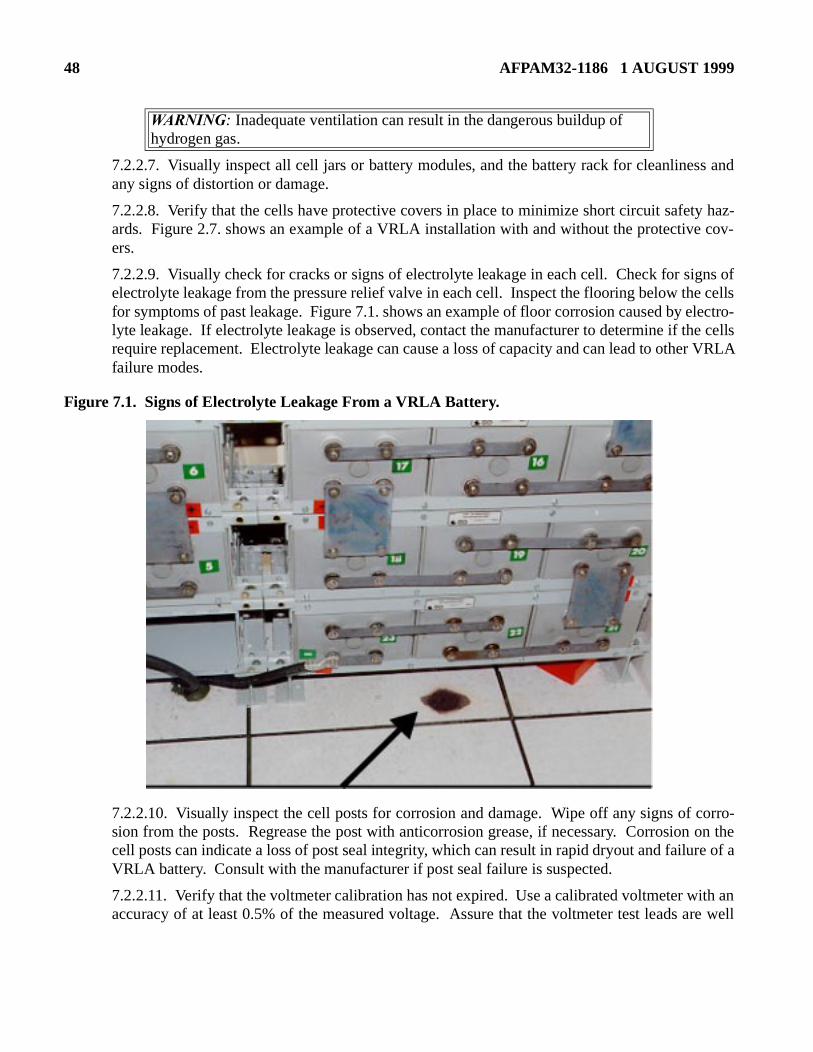
48 AFPAM32-1186 1 AUGUST 1999
7.2.2.7. Visually inspect all cell jars or battery modules, and the battery rack for cleanliness andany signs of distortion or damage.
7.2.2.8. Verify that the cells have protective covers in place to minimize short circuit safety haz-ards. Figure 2.7. shows an example of a VRLA installation with and without the protective cov-ers.
7.2.2.9. Visually check for cracks or signs of electrolyte leakage in each cell. Check for signs ofelectrolyte leakage from the pressure relief valve in each cell. Inspect the flooring below the cellsfor symptoms of past leakage. Figure 7.1. shows an example of floor corrosion caused by electro-lyte leakage. If electrolyte leakage is observed, contact the manufacturer to determine if the cellsrequire replacement. Electrolyte leakage can cause a loss of capacity and can lead to other VRLAfailure modes.
Figure 7.1. Signs of Electrolyte Leakage From a VRLA Battery.
7.2.2.10. Visually inspect the cell posts for corrosion and damage. Wipe off any signs of corro-sion from the posts. Regrease the post with anticorrosion grease, if necessary. Corrosion on thecell posts can indicate a loss of post seal integrity, which can result in rapid dryout and failure of aVRLA battery. Consult with the manufacturer if post seal failure is suspected.
7.2.2.11. Verify that the voltmeter calibration has not expired. Use a calibrated voltmeter with anaccuracy of at least 0.5% of the measured voltage. Assure that the voltmeter test leads are well
WARNING: Inadequate ventilation can result in the dangerous buildup of hydrogen gas.
AFPAM32-1186 1 AUGUST 1999 49
ratureexperi-
whichh inter-
over-e relief
insulated and securely attached to the meter to prevent their falling onto a cell and causing a shortcircuit.
7.2.2.12. Record the charger output voltage and current. Verify that the output voltage is withinthe desired range.
7.2.2.13. Measure and record the voltage at the battery terminals. Divide this measurement by thenumber of cells in the battery to confirm that the average individual cell voltage is within the rangerecommended by the manufacturer.
7.2.2.14. If float voltage is outside the recommended range, adjust the charger output to the rec-ommended value in accordance with facility procedures.
7.3. Quarterly Inspection:
7.3.1. Purpose of Inspection:
7.3.1.1. The quarterly inspection provides confirmation that the battery and individual cells arebeing maintained within recommended operating limits. Also, the quarterly inspection for aVRLA battery is intended to confirm that excessive internal battery degradation has not occurred.The following checks are specified on a quarterly basis:
7.3.1.1.1. Monthly inspection as described in Section 7.2, except the float voltage checks areperformed on all cells
7.3.1.1.2. Cell internal ohmic measurements
7.3.1.1.3. Temperature of the negative terminal of each cell
7.3.1.2. Cell internal ohmic measurements are intended to identify degraded or failed cells. Sec-tion 7.3.2. provides additional information regarding these measurements.
7.3.1.3. A check of cell temperature is prudent because a high cell temperature can indicate any ofthe following potential problems:
7.3.1.3.1. High temperatures reduce battery life by accelerating the internal corrosion rate. Acommon rule of thumb for vented lead-acid batteries is that a 8.3°C (15°F) rise in tempedecreases the expected life by 50%. For the same temperature rise, a VRLA battery ences at least the same life reduction as a vented cell.
7.3.1.3.2. High battery temperatures can contribute to thermal runaway, a condition in a battery on a constant voltage charge at an elevated temperature destroys itself througnal heat generation due to high internal current.
7.3.1.3.3. If the float voltage is too high for the actual cell temperature, the cell will be charged, leading to internal gassing and periodic venting of gases through the pressur
CAUTION: Because float voltages are accurate cell indicators only when taken on a fully charged battery, be sure that at least 72 hours have elapsed since the system was discharged or equalized.
CAUTION:Observe the proper polarity when taking voltage measurements to avoid positive and negative calibration differences in the voltmeter.
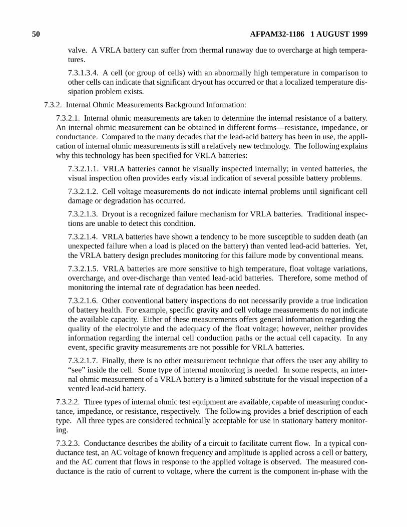
50 AFPAM32-1186 1 AUGUST 1999
nce, orthe appli-lains
, thems.
t cell
pec-
ath (ans. Yet,ans.
tions,thod of
icationdicateing thevides
n any
ility to inter-
n of a
onduc-f eachonitor-
con-battery,ed con-ith the
valve. A VRLA battery can suffer from thermal runaway due to overcharge at high tempera-tures.
7.3.1.3.4. A cell (or group of cells) with an abnormally high temperature in comparison toother cells can indicate that significant dryout has occurred or that a localized temperature dis-sipation problem exists.
7.3.2. Internal Ohmic Measurements Background Information:
7.3.2.1. Internal ohmic measurements are taken to determine the internal resistance of a battery.An internal ohmic measurement can be obtained in different forms—resistance, impedaconductance. Compared to the many decades that the lead-acid battery has been in use, cation of internal ohmic measurements is still a relatively new technology. The following expwhy this technology has been specified for VRLA batteries:
7.3.2.1.1. VRLA batteries cannot be visually inspected internally; in vented batteriesvisual inspection often provides early visual indication of several possible battery proble
7.3.2.1.2. Cell voltage measurements do not indicate internal problems until significandamage or degradation has occurred.
7.3.2.1.3. Dryout is a recognized failure mechanism for VRLA batteries. Traditional instions are unable to detect this condition.
7.3.2.1.4. VRLA batteries have shown a tendency to be more susceptible to sudden deunexpected failure when a load is placed on the battery) than vented lead-acid batteriethe VRLA battery design precludes monitoring for this failure mode by conventional me
7.3.2.1.5. VRLA batteries are more sensitive to high temperature, float voltage variaovercharge, and over-discharge than vented lead-acid batteries. Therefore, some memonitoring the internal rate of degradation has been needed.
7.3.2.1.6. Other conventional battery inspections do not necessarily provide a true indof battery health. For example, specific gravity and cell voltage measurements do not inthe available capacity. Either of these measurements offers general information regardquality of the electrolyte and the adequacy of the float voltage; however, neither proinformation regarding the internal cell conduction paths or the actual cell capacity. Ievent, specific gravity measurements are not possible for VRLA batteries.
7.3.2.1.7. Finally, there is no other measurement technique that offers the user any ab“see” inside the cell. Some type of internal monitoring is needed. In some respects, annal ohmic measurement of a VRLA battery is a limited substitute for the visual inspectiovented lead-acid battery.
7.3.2.2. Three types of internal ohmic test equipment are available, capable of measuring ctance, impedance, or resistance, respectively. The following provides a brief description otype. All three types are considered technically acceptable for use in stationary battery ming.
7.3.2.3. Conductance describes the ability of a circuit to facilitate current flow. In a typicalductance test, an AC voltage of known frequency and amplitude is applied across a cell or and the AC current that flows in response to the applied voltage is observed. The measurductance is the ratio of current to voltage, where the current is the component in-phase w
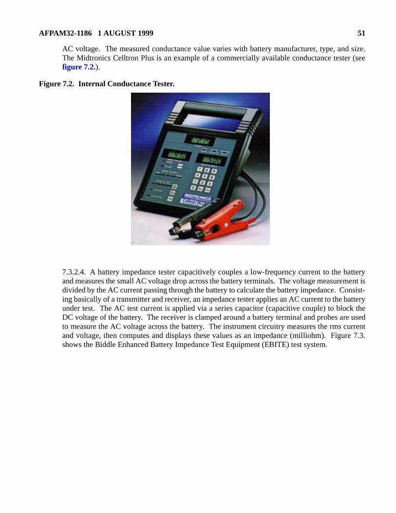
AFPAM32-1186 1 AUGUST 1999 51
AC voltage. The measured conductance value varies with battery manufacturer, type, and size.The Midtronics Celltron Plus is an example of a commercially available conductance tester (seefigure 7.2.).
Figure 7.2. Internal Conductance Tester.
7.3.2.4. A battery impedance tester capacitively couples a low-frequency current to the batteryand measures the small AC voltage drop across the battery terminals. The voltage measurement isdivided by the AC current passing through the battery to calculate the battery impedance. Consist-ing basically of a transmitter and receiver, an impedance tester applies an AC current to the batteryunder test. The AC test current is applied via a series capacitor (capacitive couple) to block theDC voltage of the battery. The receiver is clamped around a battery terminal and probes are usedto measure the AC voltage across the battery. The instrument circuitry measures the rms currentand voltage, then computes and displays these values as an impedance (milliohm). Figure 7.3.shows the Biddle Enhanced Battery Impedance Test Equipment (EBITE) test system.
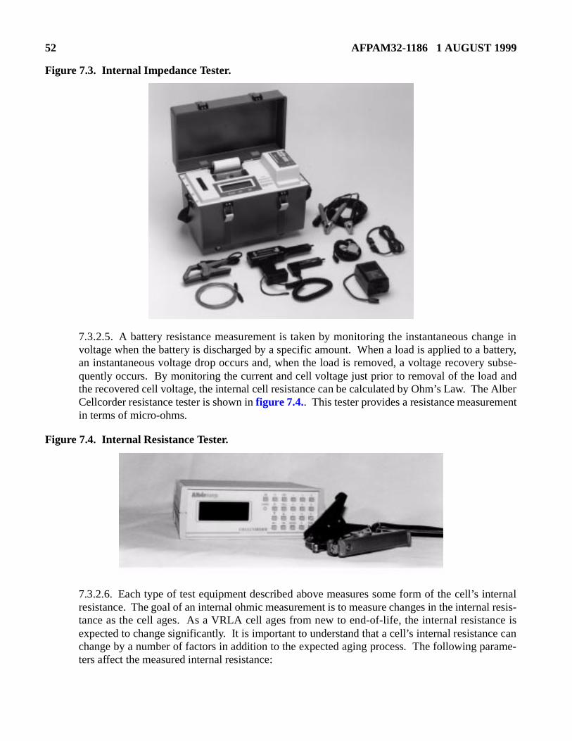
52 AFPAM32-1186 1 AUGUST 1999
e Alberent
internalal resis-nce isce canarame-
Figure 7.3. Internal Impedance Tester.
7.3.2.5. A battery resistance measurement is taken by monitoring the instantaneous change involtage when the battery is discharged by a specific amount. When a load is applied to a battery,an instantaneous voltage drop occurs and, when the load is removed, a voltage recovery subse-quently occurs. By monitoring the current and cell voltage just prior to removal of the load andthe recovered cell voltage, the internal cell resistance can be calculated by Ohm’s Law. ThCellcorder resistance tester is shown in figure 7.4.. This tester provides a resistance measuremin terms of micro-ohms.
Figure 7.4. Internal Resistance Tester.
7.3.2.6. Each type of test equipment described above measures some form of the cell’s resistance. The goal of an internal ohmic measurement is to measure changes in the interntance as the cell ages. As a VRLA cell ages from new to end-of-life, the internal resistaexpected to change significantly. It is important to understand that a cell’s internal resistanchange by a number of factors in addition to the expected aging process. The following pters affect the measured internal resistance:
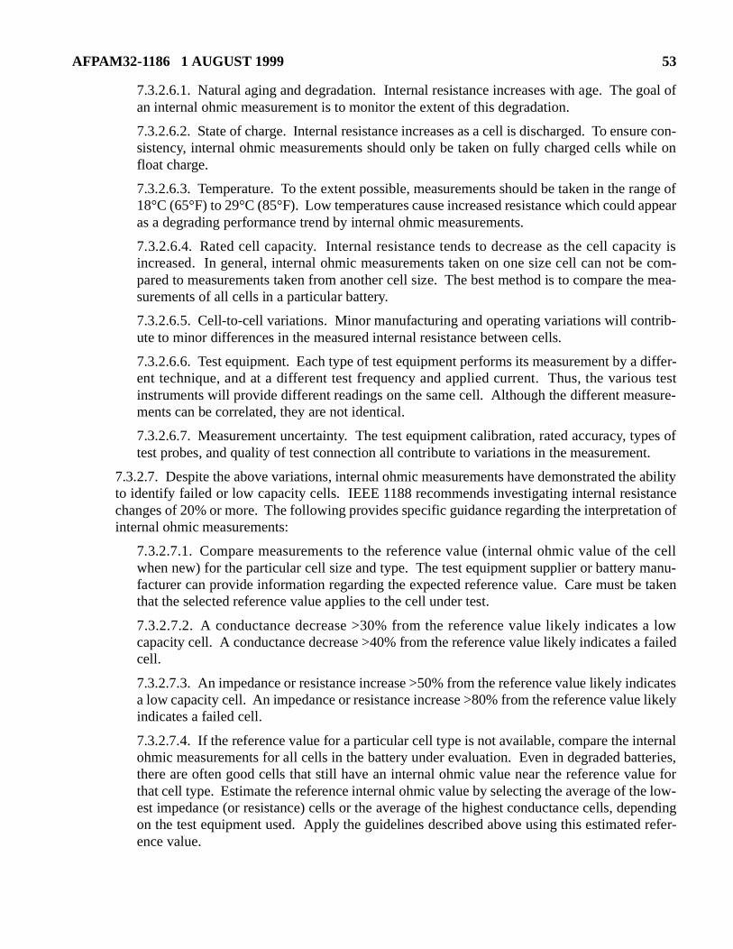
AFPAM32-1186 1 AUGUST 1999 53
appear
acity ise com-
he mea-
trib-
differ-us testsure-
pes ofnt.
e abilitytancetion of
he cellmanu-e taken
a low failed
dicatese likely
ternaltteries,lue fore low-pendingd refer-
7.3.2.6.1. Natural aging and degradation. Internal resistance increases with age. The goal ofan internal ohmic measurement is to monitor the extent of this degradation.
7.3.2.6.2. State of charge. Internal resistance increases as a cell is discharged. To ensure con-sistency, internal ohmic measurements should only be taken on fully charged cells while onfloat charge.
7.3.2.6.3. Temperature. To the extent possible, measurements should be taken in the range of18°C (65°F) to 29°C (85°F). Low temperatures cause increased resistance which couldas a degrading performance trend by internal ohmic measurements.
7.3.2.6.4. Rated cell capacity. Internal resistance tends to decrease as the cell capincreased. In general, internal ohmic measurements taken on one size cell can not bpared to measurements taken from another cell size. The best method is to compare tsurements of all cells in a particular battery.
7.3.2.6.5. Cell-to-cell variations. Minor manufacturing and operating variations will conute to minor differences in the measured internal resistance between cells.
7.3.2.6.6. Test equipment. Each type of test equipment performs its measurement by aent technique, and at a different test frequency and applied current. Thus, the varioinstruments will provide different readings on the same cell. Although the different meaments can be correlated, they are not identical.
7.3.2.6.7. Measurement uncertainty. The test equipment calibration, rated accuracy, tytest probes, and quality of test connection all contribute to variations in the measureme
7.3.2.7. Despite the above variations, internal ohmic measurements have demonstrated thto identify failed or low capacity cells. IEEE 1188 recommends investigating internal resischanges of 20% or more. The following provides specific guidance regarding the interpretainternal ohmic measurements:
7.3.2.7.1. Compare measurements to the reference value (internal ohmic value of twhen new) for the particular cell size and type. The test equipment supplier or battery facturer can provide information regarding the expected reference value. Care must bthat the selected reference value applies to the cell under test.
7.3.2.7.2. A conductance decrease >30% from the reference value likely indicatescapacity cell. A conductance decrease >40% from the reference value likely indicates acell.
7.3.2.7.3. An impedance or resistance increase >50% from the reference value likely ina low capacity cell. An impedance or resistance increase >80% from the reference valuindicates a failed cell.
7.3.2.7.4. If the reference value for a particular cell type is not available, compare the inohmic measurements for all cells in the battery under evaluation. Even in degraded bathere are often good cells that still have an internal ohmic value near the reference vathat cell type. Estimate the reference internal ohmic value by selecting the average of thest impedance (or resistance) cells or the average of the highest conductance cells, deon the test equipment used. Apply the guidelines described above using this estimateence value.
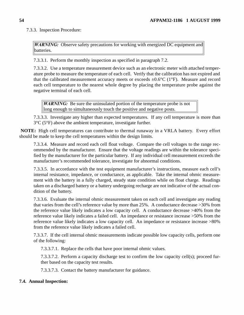
54 AFPAM32-1186 1 AUGUST 1999
d recordainst the
re than
ffort
ge rec-e speci-ds the
h cell’seasure-dings
ual con-
reading% fromom theom the >80%
m one
d fur-
7.3.3. Inspection Procedure:
7.3.3.1. Perform the monthly inspection as specified in paragraph 7.2.
7.3.3.2. Use a temperature measurement device such as an electronic meter with attached temper-ature probe to measure the temperature of each cell. Verify that the calibration has not expired andthat the calibrated measurement accuracy meets or exceeds ±0.6°C (1°F). Measure aneach cell temperature to the nearest whole degree by placing the temperature probe agnegative terminal of each cell.
7.3.3.3. Investigate any higher than expected temperatures. If any cell temperature is mo3°C (5°F) above the ambient temperature, investigate further.
NOTE: High cell temperatures can contribute to thermal runaway in a VRLA battery. Every eshould be made to keep the cell temperatures within the design limits.
7.3.3.4. Measure and record each cell float voltage. Compare the cell voltages to the ranommended by the manufacturer. Ensure that the voltage readings are within the tolerancfied by the manufacturer for the particular battery. If any individual cell measurement exceemanufacturer’s recommended tolerance, investigate for abnormal conditions.
7.3.3.5. In accordance with the test equipment manufacturer’s instructions, measure eacinternal resistance, impedance, or conductance, as applicable. Take the internal ohmic mment with the battery in a fully charged, steady state condition while on float charge. Reataken on a discharged battery or a battery undergoing recharge are not indicative of the actdition of the battery.
7.3.3.6. Evaluate the internal ohmic measurement taken on each cell and investigate any that varies from the cell’s reference value by more than 25%. A conductance decrease >30the reference value likely indicates a low capacity cell. A conductance decrease >40% frreference value likely indicates a failed cell. An impedance or resistance increase >50% frreference value likely indicates a low capacity cell. An impedance or resistance increasefrom the reference value likely indicates a failed cell.
7.3.3.7. If the cell internal ohmic measurements indicate possible low capacity cells, perforof the following:
7.3.3.7.1. Replace the cells that have poor internal ohmic values.
7.3.3.7.2. Perform a capacity discharge test to confirm the low capacity cell(s); proceether based on the capacity test results.
7.3.3.7.3. Contact the battery manufacturer for guidance.
7.4. Annual Inspection:
WARNING: Observe safety precautions for working with energized DC equipment andbatteries.
WARNING: Be sure the uninsulated portion of the temperature probe is not long enough to simultaneously touch the positive and negative posts.
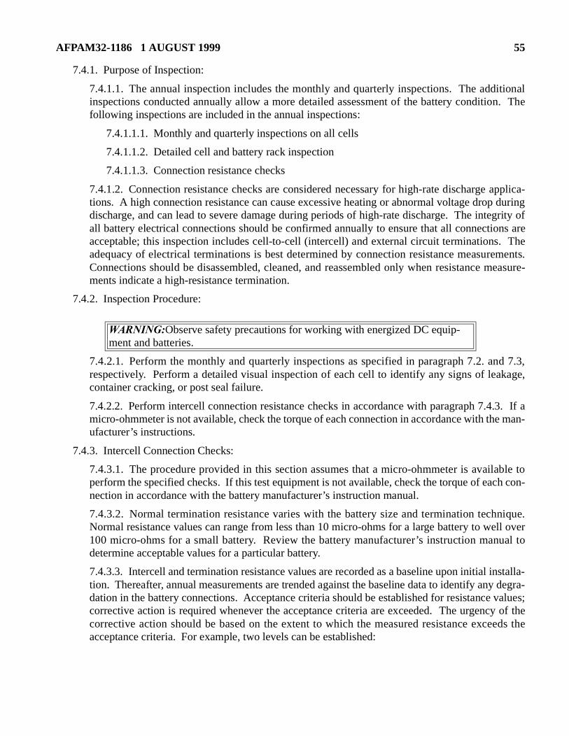
AFPAM32-1186 1 AUGUST 1999 55
able toch con-
nique.ell overual to
nstalla-y degra- values;y of theeds the
7.4.1. Purpose of Inspection:
7.4.1.1. The annual inspection includes the monthly and quarterly inspections. The additionalinspections conducted annually allow a more detailed assessment of the battery condition. Thefollowing inspections are included in the annual inspections:
7.4.1.1.1. Monthly and quarterly inspections on all cells
7.4.1.1.2. Detailed cell and battery rack inspection
7.4.1.1.3. Connection resistance checks
7.4.1.2. Connection resistance checks are considered necessary for high-rate discharge applica-tions. A high connection resistance can cause excessive heating or abnormal voltage drop duringdischarge, and can lead to severe damage during periods of high-rate discharge. The integrity ofall battery electrical connections should be confirmed annually to ensure that all connections areacceptable; this inspection includes cell-to-cell (intercell) and external circuit terminations. Theadequacy of electrical terminations is best determined by connection resistance measurements.Connections should be disassembled, cleaned, and reassembled only when resistance measure-ments indicate a high-resistance termination.
7.4.2. Inspection Procedure:
7.4.2.1. Perform the monthly and quarterly inspections as specified in paragraph 7.2. and 7.3,respectively. Perform a detailed visual inspection of each cell to identify any signs of leakage,container cracking, or post seal failure.
7.4.2.2. Perform intercell connection resistance checks in accordance with paragraph 7.4.3. If amicro-ohmmeter is not available, check the torque of each connection in accordance with the man-ufacturer’s instructions.
7.4.3. Intercell Connection Checks:
7.4.3.1. The procedure provided in this section assumes that a micro-ohmmeter is availperform the specified checks. If this test equipment is not available, check the torque of eanection in accordance with the battery manufacturer’s instruction manual.
7.4.3.2. Normal termination resistance varies with the battery size and termination techNormal resistance values can range from less than 10 micro-ohms for a large battery to w100 micro-ohms for a small battery. Review the battery manufacturer’s instruction mandetermine acceptable values for a particular battery.
7.4.3.3. Intercell and termination resistance values are recorded as a baseline upon initial ition. Thereafter, annual measurements are trended against the baseline data to identify andation in the battery connections. Acceptance criteria should be established for resistancecorrective action is required whenever the acceptance criteria are exceeded. The urgenccorrective action should be based on the extent to which the measured resistance exceacceptance criteria. For example, two levels can be established:
WARNING:Observe safety precautions for working with energized DC equip-ment and batteries.
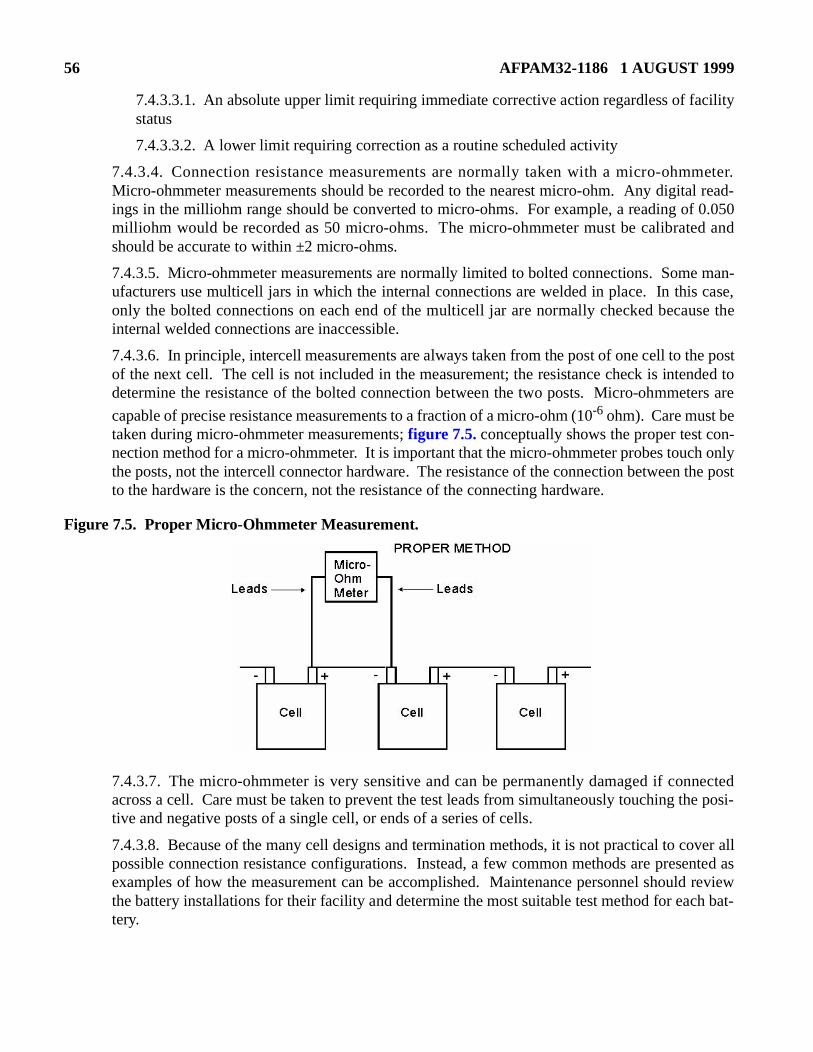
56 AFPAM32-1186 1 AUGUST 1999
man- case,se the
e postded to
ters are
n-h onlythe post
nectedhe posi-
ver allented as reviewh bat-
7.4.3.3.1. An absolute upper limit requiring immediate corrective action regardless of facilitystatus
7.4.3.3.2. A lower limit requiring correction as a routine scheduled activity
7.4.3.4. Connection resistance measurements are normally taken with a micro-ohmmeter.Micro-ohmmeter measurements should be recorded to the nearest micro-ohm. Any digital read-ings in the milliohm range should be converted to micro-ohms. For example, a reading of 0.050milliohm would be recorded as 50 micro-ohms. The micro-ohmmeter must be calibrated andshould be accurate to within ±2 micro-ohms.
7.4.3.5. Micro-ohmmeter measurements are normally limited to bolted connections. Someufacturers use multicell jars in which the internal connections are welded in place. In thisonly the bolted connections on each end of the multicell jar are normally checked becauinternal welded connections are inaccessible.
7.4.3.6. In principle, intercell measurements are always taken from the post of one cell to thof the next cell. The cell is not included in the measurement; the resistance check is intendetermine the resistance of the bolted connection between the two posts. Micro-ohmme
capable of precise resistance measurements to a fraction of a micro-ohm (10-6 ohm). Care must betaken during micro-ohmmeter measurements; figure 7.5. conceptually shows the proper test conection method for a micro-ohmmeter. It is important that the micro-ohmmeter probes toucthe posts, not the intercell connector hardware. The resistance of the connection between to the hardware is the concern, not the resistance of the connecting hardware.
Figure 7.5. Proper Micro-Ohmmeter Measurement.
7.4.3.7. The micro-ohmmeter is very sensitive and can be permanently damaged if conacross a cell. Care must be taken to prevent the test leads from simultaneously touching ttive and negative posts of a single cell, or ends of a series of cells.
7.4.3.8. Because of the many cell designs and termination methods, it is not practical to copossible connection resistance configurations. Instead, a few common methods are presexamples of how the measurement can be accomplished. Maintenance personnel shouldthe battery installations for their facility and determine the most suitable test method for eactery.
AFPAM32-1186 1 AUGUST 1999 57
r.
tercellke
the dis-onto theturement,ent.
7.4.3.9. The intercell resistance measurement is simplest for cells containing one post each for thepositive and negative terminal. The intercell connection resistance is determined by measuringthe resistance from each cell’s positive post to the next cell’s negative post (see figure 7.6.). Thereading must be obtained with the probe actually on the post, not on the intercell connecto
Figure 7.6. Single Terminal Post Resistance Measurement.
7.4.3.10. Another common design has two terminal posts on each end of the cell. The inconnection bolts onto both posts as shown in figure 7.7. Because there are four posts total, tatwo measurements as follows:
7.4.3.10.1. Terminal Post A to Terminal Post C
7.4.3.10.2. Terminal Post B to Terminal Post D
Figure 7.7. Two Terminal Post Resistance Measurement.
7.4.3.11. Inter-tier or inter-rack connections are sometimes made with cables because of tance between cells. A lug is attached to each end of the cable and the lugs are bolted appropriate cell posts. This post configuration is shown in figure 7.8. In this case, a post-to-posmeasurement is still appropriate, but because the cable resistance is included in the meastermination problems can be masked by the cable resistance contribution to the measurem
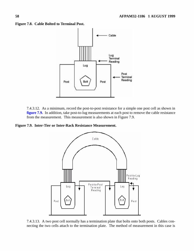
58 AFPAM32-1186 1 AUGUST 1999
Figure 7.8. Cable Bolted to Terminal Post.
7.4.3.12. As a minimum, record the post-to-post resistance for a simple one post cell as shown infigure 7.9. In addition, take post-to-lug measurements at each post to remove the cable resistancefrom the measurement. This measurement is also shown in Figure 7.9.
Figure 7.9. Inter-Tier or Inter-Rack Resistance Measurement.
7.4.3.13. A two post cell normally has a termination plate that bolts onto both posts. Cables con-necting the two cells attach to the termination plate. The method of measurement in this case is
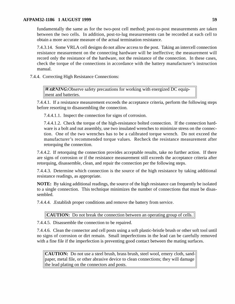
AFPAM32-1186 1 AUGUST 1999 59
uction
g steps
hard-connec-ed thent after
f thereria after
itional
olated disas-
ol untiloved
fundamentally the same as for the two-post cell method; post-to-post measurements are takenbetween the two cells. In addition, post-to-lug measurements can be recorded at each cell toobtain a more accurate measure of the actual termination resistance.
7.4.3.14. Some VRLA cell designs do not allow access to the post. Taking an intercell connectionresistance measurement on the connecting hardware will be ineffective; the measurement willrecord only the resistance of the hardware, not the resistance of the connection. In these cases,check the torque of the connections in accordance with the battery manufacturer’s instrmanual.
7.4.4. Correcting High Resistance Connections:
7.4.4.1. If a resistance measurement exceeds the acceptance criteria, perform the followinbefore resorting to disassembling the connection.
7.4.4.1.1. Inspect the connection for signs of corrosion.
7.4.4.1.2. Check the torque of the high-resistance bolted connection. If the connectionware is a bolt and nut assembly, use two insulated wrenches to minimize stress on the tion. One of the two wrenches has to be a calibrated torque wrench. Do not excemanufacturer’s recommended torque values. Recheck the resistance measuremeretorquing the connection.
7.4.4.2. If retorquing the connection provides acceptable results, take no further action. Iare signs of corrosion or if the resistance measurement still exceeds the acceptance criteretorquing, disassemble, clean, and repair the connection per the following steps.
7.4.4.3. Determine which connection is the source of the high resistance by taking addresistance readings, as appropriate.
NOTE: By taking additional readings, the source of the high resistance can frequently be isto a single connection. This technique minimizes the number of connections that must besembled.
7.4.4.4. .Establish proper conditions and remove the battery from service.
7.4.4.5. Disassemble the connection to be repaired.
7.4.4.6. Clean the connector and cell posts using a soft plastic-bristle brush or other soft tono signs of corrosion or dirt remain. Small imperfections in the lead can be carefully remwith a fine file if the imperfection is preventing good contact between the mating surfaces.
WARNING:Observe safety precautions for working with energized DC equip-ment and batteries.
CAUTION: Do not break the connection between an operating group of cells.
CAUTION: Do not use a steel brush, brass brush, steel wool, emery cloth, sand-paper, metal file, or other abrasive device to clean connections; they will damage the lead plating on the connectors and posts.
60 AFPAM32-1186 1 AUGUST 1999
s.
ing has
ed by anould be where a
o a bat-
NOTE: If the cleaning results in exposing copper underneath the lead plating, a new connector shouldbe installed. Terminal posts must be cleaned carefully because the posts cannot be replaced.
7.4.4.7. Reapply anticorrosion grease onto the connectors and posts in accordance with the man-ufacturer’s instructions.
7.4.4.8. Reinstall the connectors and torque the bolts to the manufacturer’s required value
7.4.4.9. Perform the connection resistance measurement again to confirm that the cleancorrected the problem.
7.5. Special Inspections:
7.5.1. The purpose of a special inspection is to ensure that the battery has not been damagunusual condition or event. The annual inspection, including monthly and quarterly checks, shperformed whenever the battery has experienced an unusual condition. Examples of casesVRLA battery should receive a special inspection include:
7.5.1.1. Severe discharge
7.5.1.2. Severe overcharge
7.5.1.3. Exposure to extreme high temperature
7.5.1.4. Seismic event
7.5.1.5. Exposure to abnormal environments, such as storm leakage through the roof onttery
WARNING: Apply anticorrosion grease strictly in accordance with the manu-facturer’s instructions. If the anticorrosion grease is overheated, it can exceed its flash point and start a fire.
AFPAM32-1186 1 AUGUST 1999 61
. It iscurrent manu-
he mostmpor-
tion asurs, these of thehe dutyrequire-
nstalla-
easure- require will be
st fre-shouldlts can
d ade-ired to
a par-ich a
tinuity
city testns are
Chapter 8
PERIODIC TESTS
8.1. Capacity Discharge Test (Performance Test):
8.1.1. Background Information:
8.1.1.1. A capacity test determines the extent to which a battery is capable of supplying the man-ufacturer’s rated discharge current for a given duration under a specific set of conditionsdesigned to allow trending of the battery’s capacity by discharging the battery at a constant or power to a predefined endpoint voltage and comparing the actual discharge time to thefacturer’s rated discharge time.
8.1.1.2. If the data has been properly obtained and recorded, the capacity test provides tinformation about the battery’s capacity and degree of internal deterioration. Even more itant, the user has a means of estimating where the battery is along its life curve.
8.1.1.3. .In general, the capacity test duration should correspond to the duty cycle duraclosely as possible. For example, if the battery was sized to provide a certain load for 2 hocapacity test should also be conducted at the manufacturer’s 2-hour discharge rate. Becaumargins normally designed into the battery size, a capacity test duration corresponding to tcycle duration should provide reasonable assurance that the battery can meet its design ments.
8.1.2. Test Frequency:
8.1.2.1. A capacity test should be performed as part of the acceptance testing of a new ition.
8.1.2.2. Perform a capacity test as necessary to resolve discrepancies in internal ohmic mments (see paragraph 7.3.2). Depending on the warranty, the battery manufacturer mightcapacity test data rather than internal ohmic measurement data before a warranty claimhonored.
8.1.2.3. For critical installations, perform a capacity test every 2 years. The basis for this tequency (longer than specified in IEEE 1188) is that quarterly internal ohmic measurements also identify signs of degradation. As noted above, internal ohmic measurement test resulead to the performance of a capacity test.
8.1.2.4. For non-critical applications, quarterly internal ohmic measurements are considerequate; periodic capacity tests are not specified. However, a capacity test might still be requresolve signs of degradation from the internal ohmic measurement data.
8.1.2.5. With regard to capacity testing, each facility is responsible for determining whetherticular installation is designated as critical or non-critical. A critical installation is one in whloss of power can not be tolerated.
8.1.2.6. If a capacity test is specified and the test equipment is not available, perform a contest instead in accordance with paragraph 8.2.
8.1.2.7. A stationary battery used in an engine starting application does not require a capaif the battery periodically starts the engine. The monthly, quarterly, and annual inspectio
62 AFPAM32-1186 1 AUGUST 1999
or theeraturers for a
or con-t of heat
attery.
adjusted
still required for stationary engine starting batteries. Note that this manual does not apply tomotive power batteries.
8.1.3. Initial Conditions for Test:
8.1.3.1. Equalize the battery only if recommended by the manufacturer and return it to floatcharge for a minimum of 72 hours but less than 30 days before the start of the test.
NOTE: Some manufacturers do not recommend equalizing VRLA batteries to minimize gassing andwater consumption. In general, an equalize charge should not be required specifically for a capacity test.
8.1.3.2. Check all battery connections and ensure that battery connection resistance measure-ments are within the expected tolerances. Correct any potential problems before starting the test.
8.1.3.3. Measure and record the float voltage of each cell just prior to the test.
8.1.3.4. Measure and record the cell temperature of 10% or more of the cells just prior to the testto establish an average temperature.
8.1.3.5. Measure and record the battery terminal float voltage.
8.1.3.6. Take adequate precautions (such as isolating the battery to be tested from the DC system)to ensure that a failure will not affect other equipment.
8.1.4. Capacity Test Procedure:
8.1.4.1. Verify that the pretest requirements described in paragraph 8.1.3. have been completed.
8.1.4.2. Verify that the battery area ventilation is operating normally.
8.1.4.3. Determine the discharge rate by dividing the manufacturer’s rated discharge (fdesired duration) by the appropriate temperature correction factor (based on the cell tempreadings). Consult the manufacturer for the proper discharge temperature correction factospecific battery.
8.1.4.4. Set up a test discharge load capable of maintaining the required constant currentstant power test discharge rate. The load bank typically generates a considerable amounduring the test; locate the load bank where it will not overheat other installed equipment.
8.1.4.5. Disconnect the battery charger from the battery and connect the load bank to the b
NOTES:If the battery charger cannot be disconnected from the battery, the test discharge rate must beto compensate for the battery charger contribution.
WARNING:Observe safety precautions for working with energized DC equip-ment and batteries.
CAUTION: Be careful not to short-circuit the battery while making the con-nections to the load bank. One approach is to connect the cables first to the load bank, followed by the connection to the battery. The reason for this order of events is that the connection of the positive and negative leads at the load bank can be very close together with little room for error.
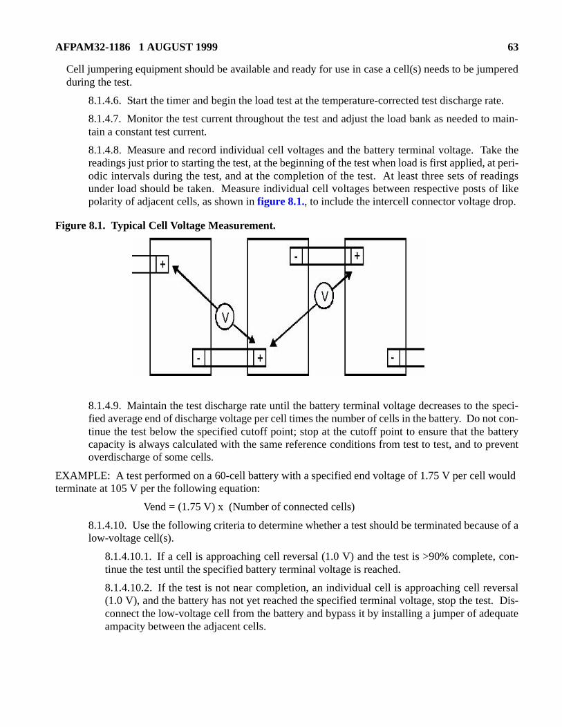
AFPAM32-1186 1 AUGUST 1999 63
Cell jumpering equipment should be available and ready for use in case a cell(s) needs to be jumperedduring the test.
8.1.4.6. Start the timer and begin the load test at the temperature-corrected test discharge rate.
8.1.4.7. Monitor the test current throughout the test and adjust the load bank as needed to main-tain a constant test current.
8.1.4.8. Measure and record individual cell voltages and the battery terminal voltage. Take thereadings just prior to starting the test, at the beginning of the test when load is first applied, at peri-odic intervals during the test, and at the completion of the test. At least three sets of readingsunder load should be taken. Measure individual cell voltages between respective posts of likepolarity of adjacent cells, as shown in figure 8.1., to include the intercell connector voltage drop.
Figure 8.1. Typical Cell Voltage Measurement.
8.1.4.9. Maintain the test discharge rate until the battery terminal voltage decreases to the speci-fied average end of discharge voltage per cell times the number of cells in the battery. Do not con-tinue the test below the specified cutoff point; stop at the cutoff point to ensure that the batterycapacity is always calculated with the same reference conditions from test to test, and to preventoverdischarge of some cells.
EXAMPLE: A test performed on a 60-cell battery with a specified end voltage of 1.75 V per cell would terminate at 105 V per the following equation:
Vend = (1.75 V) x (Number of connected cells)
8.1.4.10. Use the following criteria to determine whether a test should be terminated because of alow-voltage cell(s).
8.1.4.10.1. If a cell is approaching cell reversal (1.0 V) and the test is >90% complete, con-tinue the test until the specified battery terminal voltage is reached.
8.1.4.10.2. If the test is not near completion, an individual cell is approaching cell reversal(1.0 V), and the battery has not yet reached the specified terminal voltage, stop the test. Dis-connect the low-voltage cell from the battery and bypass it by installing a jumper of adequateampacity between the adjacent cells.
64 AFPAM32-1186 1 AUGUST 1999
ore it to
r than
terminepacityo war- unac-
atteryattery
8.1.4.10.3. Calculate the new battery end terminal voltage limit due to removal of the cell andrestart the test.
EXAMPLE: If the test termination voltage was 105 V for 60 cells based on 1.75 V per cell, the new test termination voltage would be 103.25 V if one cell is jumpered out.
NOTES:Once a cell has reached 1.0 V, the cell voltage drops rapidly and the cell is nearing or has reached com-plete exhaustion. Continuing the test without jumpering the cell is acceptable only if the test is nearcompletion.
The time required to jumper a cell and restart the test should be minimized. The downtime should beless than 10% of the intended test duration or 6 minutes, whichever is shorter. A longer downtimeallows the battery to recover capacity. The downtime should not be included as part of the total dura-tion of the capacity test.
Only one downtime is allowed per test. Additional downtimes allow the battery to recover and falselyindicate a higher battery capacity.
8.1.4.11. Observe the battery during the test for intercell connector heating.
8.1.4.12. Terminate the test when the battery terminal voltage decreases to the calculated endvoltage. Record the total test time.
8.1.4.13. Disconnect the test equipment.
8.1.4.14. Recharge the battery in accordance with the manufacturer’s instructions and restnormal standby service.
8.1.4.15. Calculate battery capacity using the following equation for discharge times greate1 hour:
Percent capacity (77°F) = (Ta/Ts) x 100
where:
Ta = actual time of test to specified terminal voltage
Ts = manufacturer’s rated time to specified terminal voltage
8.1.4.16. Compare the battery capacity to that obtained by previous capacity tests to dethe trend in battery capacity. A lead-acid battery typically requires replacement when its cahas fallen to 80% of its rated capacity. Determine whether battery degradation is sufficient trant more frequent capacity testing. Evaluate the performance of individual cells to identifyceptable cells.
8.2. Continuity Test:
8.2.1. Background Information:
8.2.1.1. A continuity test is a short duration test of the battery’s capacity by having the bcarry the system load. A continuity test is normally initiated by turning off the associated bcharger.
AFPAM32-1186 1 AUGUST 1999 65
should, deter- dis-the teston cri-
st byed forration.
e manu-
8.2.1.2. A continuity test is to be performed instead of a capacity test (see paragraph 8.1) if capac-ity test equipment is not available.
8.2.1.3. A continuity test requires close monitoring of battery voltage throughout the test toensure that a loss of power does not occur.
8.2.2. Procedure:
8.2.2.1. Before starting a continuity test, check the charger output current to determine the systemload. Review the manufacturer’s data sheet for the battery to predict how long the battery be capable of carrying this load. Based on the total load and the battery’s rated capabilitymine how long to conduct the continuity test; it is not intended that a continuity test fullycharge the battery. The battery should have greater than 50% of its original capacity when is complete. Also, determine the minimum allowed DC voltage and establish test terminatiteria above this minimum voltage.
8.2.2.2. Initiate the continuity test by turning off the battery charger.
8.2.2.3. Constantly monitor battery voltage during the continuity test. Terminate the tere-energizing the battery charger if the battery voltage falls to the low voltage limit establishthe test. Otherwise, terminate the test when the battery has discharged for the planned du
8.2.2.4. Evaluate the test results by comparing the discharge rate and discharge time to thfacturer’s rating for the battery.
CAUTION:
Conduct a continuity test during stable system conditions (no thunderstorms or other events that might require battery backup power). Because the battery is partially discharged by the continuity test, stable system conditions are needed to ensure that the battery is recharged as soon as possible.
CAUTION:
Monitor battery voltage closely at the beginning of the test. Immediately restore power to the charger if battery voltage is falling rapidly.
66 AFPAM32-1186 1 AUGUST 1999
ld be
ld allow
asure-e life orattery. first 4
at wasility or
place-
inallyat the
than just to
he last
Chapter 9
INSTALLATION AND REPLACEMENT
9.1. Replacement Criteria:
9.1.1. Over the life of any backup power system, the installed battery eventually requires replace-ment. When the predicted end of life for a battery is less than 2 years away, the impending need forreplacement should be identified and budgeted. Larger battery installations should be planned as farin advance as possible. Smaller batteries might not need as much lead-time for evaluation.
9.1.2. Any of the following conditions can require a battery replacement:
9.1.2.1. Capacity below, at, or approaching 80% (as determined by a capacity test)
9.1.2.2. Age approaching the manufacturer’s predicted service life
9.1.2.3. Continuity test indicating low battery capacity
9.1.2.4. Excessive number of individual cell failures such that the entire battery shoureplaced rather than individual cells
9.1.2.5. Load growth that prevents the battery from meeting its load requirements
9.1.2.6. New or revised design requirements
9.1.2.7. Severe battery degradation
9.1.3. Except for cases of sudden battery degradation, trending of battery performance shoumaintenance personnel to predict when replacement will be necessary.
9.1.4. Individual cells might require replacement when a capacity test or an internal ohmic mement determines that they are degraded. Unless the battery is nearing the end of its servicmany cells in the battery are degraded, it is acceptable to replace individual cells within the bBased on industry experience to date, it is likely that some cells will require replacement in theyears of service.
9.2. Battery Size Verification:
9.2.1. Some well-built and well-maintained batteries can last for many years. For a battery thoriginally installed several years ago, it is possible that the design of other equipment in the facthe design criteria for the facility has changed. Consider the following sizing guidelines for rement batteries:
9.2.1.1. The facility might have more load on the battery than anticipated when it was origsized. A load check should be performed as part of a battery replacement to confirm threplacement battery is properly sized.
9.2.1.2. The original criteria for battery sizing might have assumed a shorter duty cycledesirable for newer installations today. Replacement batteries could require a larger sizemeet the current criteria for the facility.
9.2.1.3. Verify the manufacturer’s performance ratings for the battery. In the years since tbattery was installed, battery manufacturers might have changed the battery ratings.
AFPAM32-1186 1 AUGUST 1999 67
9.2.1.4. Verify, if possible, that the original battery was properly sized, including allowances foraging, temperature, and design margin. It is possible that the battery was too small to fulfill itsoriginal design requirements with all factors considered.
9.3. Design Verification for a Replacement Battery Larger Than the Original:
9.3.1. If the decision is made to replace a battery with a larger battery, check the following systemdesign features:
9.3.1.1. Verify that the larger battery, including the new battery rack will physically fit within theavailable footprint and that the allowable floor loading is not exceeded.
9.3.1.2. Check the new battery fault current and determine if protective devices and distributionequipment are still within their interrupting or withstand ratings.
9.3.1.3. Determine if the existing charger can recharge the battery in a reasonable time. A largercharger might be required as part of the battery replacement.
9.3.1.4. Verify that the battery cables are large enough to carry the larger battery output current.
9.4. Check of Other Equipment:
9.4.1. For a good battery installation, a battery replacement is a relatively rare event. The rest of thesystem should be inspected and upgraded, as needed, as part of the battery replacement. While thebattery is out of service for replacement, perform the following:
9.4.1.1. Inspect DC system breakers.
9.4.1.2. Inspect cabling for aging or damage. Replace as necessary.
9.4.1.3. nspect the battery rack for damage or corrosion. Replace as necessary.
9.4.1.4. Replace older fuses in the DC system as a precautionary measure.
9.4.2. The charger should receive special attention as part of a battery replacement. Complete the fol-lowing:
9.4.2.1. If the new battery has a larger capacity, confirm that the charger size is still adequate.
9.4.2.2. Check the voltmeter calibration at the float and equalize voltages.
9.4.2.3. Check for loose connections and evidence of overheating.
9.4.2.4. Check the charger failure alarm by opening the AC breaker. Check the setting of othervoltage relays.
9.4.2.5. Inspect contacts on relays for signs of pitting or burning.
9.4.2.6. Evaluate the output filter capacitors and replace if necessary.
9.4.3. As part of the battery replacement, make everything in the system as new as possible, not justthe battery. The other equipment also ages. If it is not inspected and upgraded during the batteryreplacement, it might be many years before it is looked at closely again.
9.5. Maintenance Checks of a New Battery:
68 AFPAM32-1186 1 AUGUST 1999
attery.
accor-
nufac-
ns. Ifeasure-
ot per-dequatete the
ohmic
d war-eriod,rranty originalcement
inte-ystemfirst 3ro-rated
formed. Thered on the
ration to theen fail
mainte-
9.5.1. Review all manufacturer’s recommendations for the installation and operation of the bThe installed location and configuration must comply with the manufacturer’s requirements.
9.5.2. Perform the following maintenance-related tasks as part of the installation:
9.5.2.1. Inspect all cells for damage before installation. Verify that the cells were stored in dance with the manufacturer’s recommendations.
9.5.2.2. Once the battery is installed, apply an initial charge in accordance with the maturer’s recommendations.
9.5.2.3. Torque all intercell connections in accordance with the manufacturer’s specificatioa micro-ohmmeter is available, take a baseline set of intercell and termination resistance mments. These resistance measurements will form the basis for future acceptance criteria.
9.5.2.4. Record baseline internal ohmic measurements for all cells.
9.5.2.5. A capacity test is recommended as part of the installation if the manufacturer did nform an acceptance test before shipment. The purpose of this capacity test is to confirm abattery capacity and to identify any failed cells. If a capacity test is not performed, evaluainternal ohmic measurements to ensure that all cells are consistent. Abnormal internalmeasurements might still require a capacity test to ensure that the battery is acceptable.
9.6. Warranty Considerations:
9.6.1. Most manufacturers offer a 1 or 2 year complete replacement warranty with a pro-rateranty thereafter for larger stationary batteries. If the battery fails during the full-replacement pthe manufacturer will usually replace it at no charge. After the full-replacement period, the wais pro-rated based on the number of months in service, with the pro-rated amount based on thebattery cost. The pro-rated amount is normally applied as a credit to the current price of a replabattery. Shipping and installation costs are usually excluded from the warranty.
9.6.2. The Power Conditioning and Continuation Interfacing Equipment (PCCIE) Special Manance Team (SMT) has negotiated a different warranty for certain uninterruptible power s(UPS) equipment. The contract was written with a full replacement of the battery within the years for any defects in materials and workmanship. After the first 3 years, the battery has a pwarranty for an additional 3 years.
9.6.3. The manufacturer’s warranty usually specifies required maintenance that must be perand records that must be kept so as to document that the battery was properly maintainedmight also be restrictions on the average ambient temperature or the number of cycles placebattery.
9.6.4. The warranty, including full-replacement and pro-rated periods, is a commercial consideestablished by the manufacturer. The warranty period might not have a direct relationshipactual expected service life. For example, several studies have shown that VRLA cells oftwithin 4 to 7 years, despite having a 20-year warranty.
9.7. Life Cycle Management:
9.7.1. A good system design balances the technical requirements with the cost and ongoing nance requirements. Consider the following factors when selecting the battery size and type:
AFPAM32-1186 1 AUGUST 1999 69
attery’s
enancements of
ically
. Thece.
9.7.1.1. Application and duty cycle requirements
9.7.1.2. System interface limitations
9.7.1.3. Service environment
9.7.1.4. Initial equipment cost
9.7.1.5. Installation cost
9.7.1.6. Ongoing maintenance cost
9.7.1.7. Periodic replacement cost
9.7.2. Some battery life cycle work sheets have shown a substantial savings for VRLA batteries(based on the assumption of a 20-year life and virtually no maintenance). An assessment of a bactual cost must be based on realistic life projections; consider the following costs:
9.7.2.1. Initial purchase of battery and rack, including freight.
9.7.2.2. Estimated installation cost, if different for the various battery types.
9.7.2.3. Periodic maintenance expense. The cost of monthly, quarterly, and annual maintshould be assessed. Estimate maintenance costs for VRLA batteries based on the requirethis AFMAN.
9.7.2.4. Periodic replacement.
9.7.3. Assume a service life of 8 years for life cycle calculations of VRLA batteries. This is typshorter than the warranty life, but is based on the industry experience to date.
9.7.4. For life cycle planning, schedule replacement of long-life VRLA batteries every 8 yearsreplacement schedule can be extended if maintenance records indicate acceptable performan
JOHN W. HANDY, Lt General, USAFDCS/Installation & Logistics
70 AFPAM32-1186 1 AUGUST 1999
Attachment 1
GLOSSARY OF REFERENCES AND SUPPORTING INFORMATION
References
The most recent edition of referenced publications applies, unless otherwise specified.
IEEE 1187-1996, IEEE Recommended Practice for Installation Design and Installation of Valve-Regu-lated Lead-Acid Storage Batteries for Stationary Applications
IEEE 1188-1996, IEEE Recommended Practice for Maintenance, Testing, and Replacement of Valve Reg-ulated Lead-Acid Storage Batteries for Stationary Applications
IEEE 1189-1996, Guide for Selection of Valve Regulated Lead-Acid Storage Batteries for StationaryApplications
IEEE 1184-1994, IEEE Guide for the Selection and Sizing of Batteries for Uninterruptible Power Systems
NFPA 70, National Electrical Code
NFPA 101, The Life Safety Code
AFJMAN 32-1280(I), Facilities Engineering Electrical Exterior Facilities
AFJMAN 32-1281(I), Facilities Engineering Electrical Interior Facilities
Terms
Acceptance Test—A constant current or power capacity test made on a new battery to determine whetherit meets specifications or manufacturer’s ratings.
Active Materials—The materials of the plates which react chemically to produce electrical energy whenthe cell discharges and which are restored to their original composition, in the charged condition, by achemical reaction produced by the charging current.
Ampere-Hour Capacity—The number of ampere-hours that can be delivered under specifiedconditions, including temperature, rate of discharge, and final voltage.
Battery—Two or more cells connected to form one unit for producing electric energy at the requiredvoltage and current levels.
Capacity—Ampere-hours available from a fully charged cell or battery.
Capacity Test—A discharge of a battery at a constant current or power to a designated terminal voltage.
Cell—An electrochemical device, composed of positive and negative plates, separator, and electrolyte,that is capable of storing electrical energy; when encased in a container and fitted with terminals, it is thebasic component of a battery.
Charge—The conversion of electrical energy into chemical energy within the cell or battery. Thisrestoration of the active materials is accomplished by maintaining a unidirectional current in the cell orbattery in the opposite direction to that during discharge. A cell or battery that is said to be charged isunderstood to be fully charged.
Cycle—A battery discharge followed by a complete recharge. A deep, or full, cycle is described as the
AFPAM32-1186 1 AUGUST 1999 71
removal and replacement of 80% or more of the cell’s design capacity.
DC—Direct current.
Discharge Rate—The rate, usually expressed in amperes, at which electrical current is taken from thecell or battery.
Discharging—The withdrawing of electrical energy from a battery or cell.
Electrolyte—The conducting medium in which the flow of electric current takes place by the migrationof ions. For example, the electrolyte for a lead-acid cell is an aqueous solution of sulfuric acid.
Equalize Charge—An extended charge to a measured end point that is given to a storage battery toinsure the complete restoration of the active materials in all plates of the cells.
Float Charge—The method of maintaining a cell or battery in a charged condition by continuous,long-term constant-voltage charging at a level to balance self-discharge.
Float Voltage—The voltage applied to a battery to maintain the proper voltage for each cell of the batteryduring normal operation.
IEEE— Institute of Electrical and Electronics Engineers, Inc.
Internal Conductance—A measure of the ability of a cell or battery to facilitate current flow.Conductance is related to the inverse of impedance and resistance.
Internal Impedance—The opposition or resistance of a cell or battery to an alternating current of aparticular frequency.
Internal Resistance—The opposition or resistance to electrical current flow within a cell or battery. Itsvalue is dependent upon battery design, state of charge, temperature, and age.
Negative Plate—Consists of the grid and active material to which current flows from the external circuitwhen the battery is discharging.
Negative Terminal—The terminal toward which positive electric charge flows in the external circuitfrom the positive terminal when the cell discharges.
Nominal Gravity— The specific gravity of the electrolyte selected for the determination of the ratedcapacity of the storage battery when it is fully charged and correctly leveled.
Nominal Voltage—The characteristic operating voltage or rated voltage of a cell or battery.
Open Circuit Voltage—The voltage at a cell or battery terminals when no appreciable current is flowing.
Overcharging—Continuing charge after the battery has accepted its maximum amount of charge. In avented cell, a result will be decomposition of water in the electrolyte into hydrogen and oxygen gases. Ina VRLA cell, a result will be increased cell temperature and venting of gases through the pressure reliefvalve.
Oxygen Recombination—The electrochemical process in which oxygen generated at the positive plateduring overcharge is reacted (reduced) with water at the negative plate at the same time, therebyproducing heat.
Periodic Test—A test performed at scheduled intervals to detect failures and verify operability.
Polarization—The change in voltage at the terminals of the cell or battery when a specified current is
72 AFPAM32-1186 1 AUGUST 1999
flowing; it is equal to the difference between the actual and the equilibrium (constant open-circuitcondition) potentials of the plates, exclusive of the internal resistance drop.
Positive Plate—The grid and active material from which current flows to the external circuit when thebattery is discharging.
Positive Terminal—The terminal from which the positive electric charge flows through the externalcircuit to the negative terminal when the cell discharges.
Rated Capacity—The ampere-hour capacity assigned to a storage cell by its manufacturer for a givendischarge time, at a specified electrolyte temperature and specific gravity, to a given end-of-dischargevoltage.
Recombinant Cell—A cell designed so that generated oxygen and hydrogen are recombined to formwater rather than being vented from the cell (see Valve-Regulated Lead-Acid Cell).
Recombination—The chemical reaction of gases at the electrodes to form a nongaseous product.
Self-Discharge—The spontaneous decomposition of battery materials from a charged to a dischargedstate.
Stationary Battery—A storage battery designed for service in a permanent location.
Thermal Runaway—A condition whereby a battery on constant-potential charge at elevated temperaturewill destroy itself through internal heat generation due to high internal currents.
Undercharging—Applying less than the amount of current required to recharge a battery.
UPS—Uninterruptible Power System.
Valve-Regulated Lead-Acid (VRLA) Cell—A lead-acid cell that is sealed with the exception of a valvethat opens to the atmosphere when the internal gas pressure in the cell exceeds the atmospheric pressureby a pre-selected amount. VRLA cells provide a means of recombination of internally generated oxygenand the suppression of hydrogen gas evolution to limit water consumption.
VRLA— Valve-regulated lead-acid.