Embed Size (px)
Citation preview
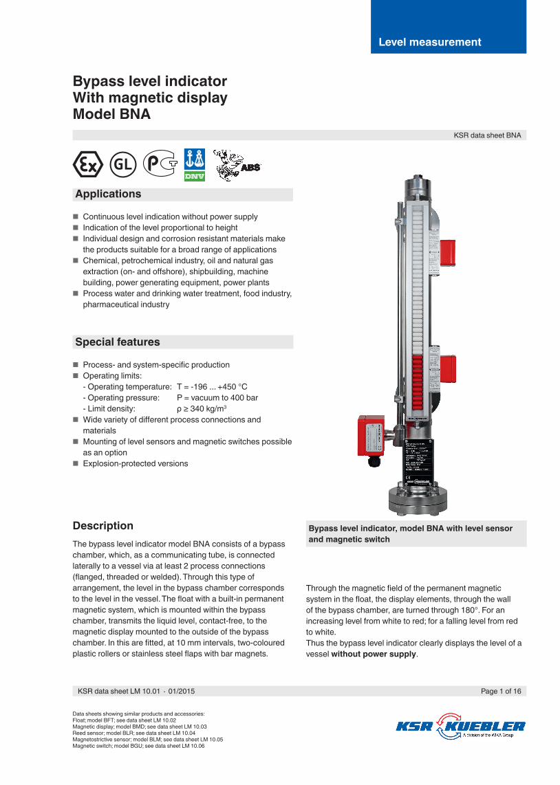
Bypass level indicatorWith magnetic displayModel BNA
Bypass level indicator, model BNA with level sensor and magnetic switch
Applications
■ Continuous level indication without power supply ■ Indication of the level proportional to height ■ Individual design and corrosion resistant materials make
the products suitable for a broad range of applications ■ Chemical, petrochemical industry, oil and natural gas
extraction (on- and off shore), shipbuilding, machine building, power generating equipment, power plants
■ Process water and drinking water treatment, food industry, pharmaceutical industry
Special features
■ Process- and system-specifi c production ■ Operating limits:
- Operating temperature: T = -196 ... +450 °C- Operating pressure: P = vacuum to 400 bar- Limit density: ρ ≥ 340 kg/m3
■ Wide variety of diff erent process connections and materials
■ Mounting of level sensors and magnetic switches possible as an option
■ Explosion-protected versions
DescriptionThe bypass level indicator model BNA consists of a bypass chamber, which, as a communicating tube, is connected laterally to a vessel via at least 2 process connections (fl anged, threaded or welded). Through this type of arrangement, the level in the bypass chamber corresponds to the level in the vessel. The fl oat with a built-in permanent magnetic system, which is mounted within the bypass chamber, transmits the liquid level, contact-free, to the magnetic display mounted to the outside of the bypass chamber. In this are fi tted, at 10 mm intervals, two-coloured plastic rollers or stainless steel fl aps with bar magnets.
Through the magnetic fi eld of the permanent magnetic system in the fl oat, the display elements, through the wall of the bypass chamber, are turned through 180°. For an increasing level from white to red; for a falling level from red to white.Thus the bypass level indicator clearly displays the level of a vessel without power supply.
Level measurement
Data sheets showing similar products and accessories:Float; model BFT; see data sheet LM 10.02Magnetic display; model BMD; see data sheet LM 10.03Reed sensor; model BLR; see data sheet LM 10.04Magnetostrictive sensor; model BLM; see data sheet LM 10.05Magnetic switch; model BGU; see data sheet LM 10.06
KSR data sheet BNA
Page 1 of 16KSR data sheet LM 10.01 ∙ 01/2015
Page 2 of 16 KSR data sheet LM 10.01 ∙ 01/2015
Further special features
■ Simple, robust and solid design, long service life ■ Bypass chamber and float from stainless steel 1.4571,
1.4404 or special materials ■ Pressure- and gas-tight separation between measuring
and display chamber ■ Measuring and indicating of the level of aggressive,
combustible, toxic, hot and contaminated media ■ Functioning of the magnetic display guaranteed even in
the case of power failures ■ By using a variety of corrosion-resistant materials,
applicable for virtually all industrial applications ■ Continuous measurement of levels, independent of
physical and chemical changes of the media such as: Foaming, conductivity, dielectric constant, vapours, bubble formation, boiling effects
■ Interface-layer level measurement from ∆ density 100 kg/m3
■ Special versions: Food compliant, coatings, liquid gas, heating jacket
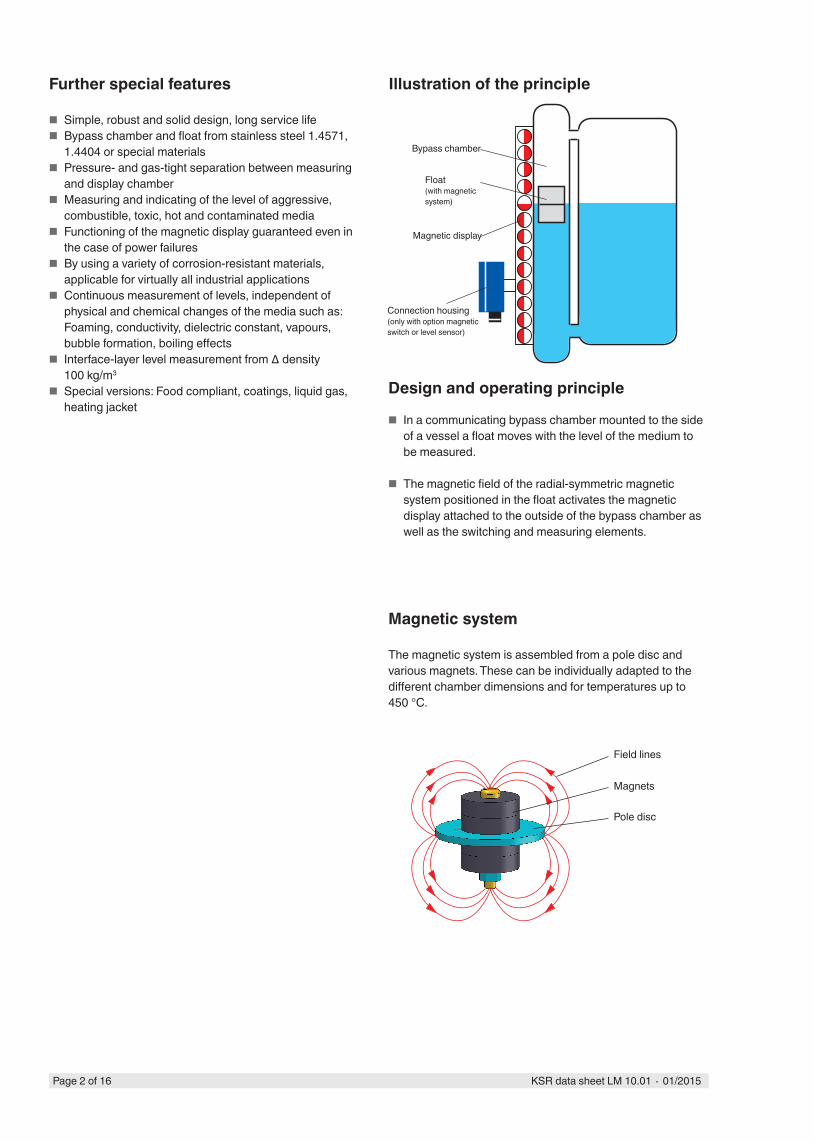
Illustration of the principle
Design and operating principle
■ In a communicating bypass chamber mounted to the side of a vessel a float moves with the level of the medium to be measured.
■ The magnetic field of the radial-symmetric magnetic system positioned in the float activates the magnetic display attached to the outside of the bypass chamber as well as the switching and measuring elements.
Connection housing(only with option magnetic switch or level sensor)
Magnetic display
Float(with magnetic system)
Bypass chamber
Magnetic system
The magnetic system is assembled from a pole disc and various magnets. These can be individually adapted to the different chamber dimensions and for temperatures up to 450 °C.
Field lines
Magnets
Pole disc
Page 3 of 16KSR data sheet LM 10.01 ∙ 01/2015
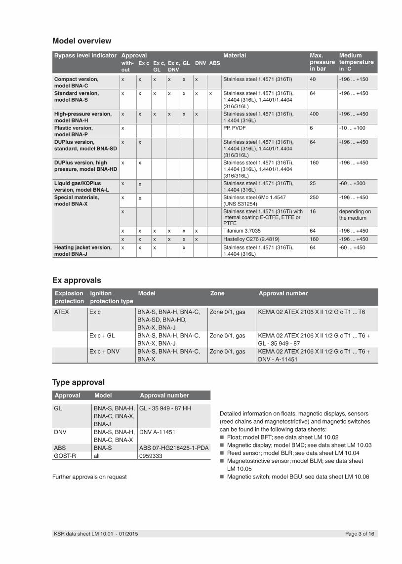
Model overviewBypass level indicator Approval Material Max.
pressure in bar
Medium temperature in °C
with-out
Ex c Ex c, GL
Ex c, DNV
GL DNV ABS
Compact version, model BNA-C
x x x x x x Stainless steel 1.4571 (316Ti) 40 -196 ... +150
Standard version, model BNA-S
x x x x x x x Stainless steel 1.4571 (316Ti), 1.4404 (316L), 1.4401/1.4404 (316/316L)
64 -196 ... +450
High-pressure version, model BNA-H
x x x x x x Stainless steel 1.4571 (316Ti), 1.4404 (316L)
400 -196 ... +450
Plastic version, model BNA-P
x PP, PVDF 6 -10 ... +100
DUPlus version, standard, model BNA-SD
x x Stainless steel 1.4571 (316Ti), 1.4404 (316L), 1.4401/1.4404 (316/316L)
64 -196 ... +450
DUPlus version, high pressure, model BNA-HD
x x Stainless steel 1.4571 (316Ti), 1.4404 (316L), 1.4401/1.4404 (316/316L)
160 -196 ... +450
Liquid gas/KOPlus version, model BNA-L
x x Stainless steel 1.4571 (316Ti), 1.4404 (316L)
25 -60 ... +300
Special materials, model BNA-X
x x Stainless steel 6Mo 1.4547 (UNS S31254)
250 -196 ... +450
x Stainless steel 1.4571 (316Ti) with internal coating E-CTFE, ETFE or PTFE
16 depending on the medium
x x x x x x Titanium 3.7035 64 -196 ... +450x x x x x x Hastelloy C276 (2.4819) 160 -196 ... +450
Heating jacket version, model BNA-J
x x x x Stainless steel 1.4571 (316Ti), 1.4404 (316L)
64 -60 ... +450
Ex approvalsExplosion protection
Ignition protection type
Model Zone Approval number
ATEX Ex c BNA-S, BNA-H, BNA-C, BNA-SD, BNA-HD, BNA-X, BNA-J
Zone 0/1, gas KEMA 02 ATEX 2106 X ll 1/2 G c T1 ... T6
Ex c + GL BNA-S, BNA-H, BNA-C, BNA-X, BNA-J
Zone 0/1, gas KEMA 02 ATEX 2106 X ll 1/2 G c T1 ... T6 + GL - 35 949 - 87
Ex c + DNV BNA-S, BNA-H, BNA-C, BNA-X
Zone 0/1, gas KEMA 02 ATEX 2106 X ll 1/2 G c T1 ... T6 + DNV - A-11451
Type approvalApproval Model Approval number
GL BNA-S, BNA-H, BNA-C, BNA-X, BNA-J
GL - 35 949 - 87 HH
DNV BNA-S, BNA-H, BNA-C, BNA-X
DNV A-11451
ABS BNA-S ABS 07-HG218425-1-PDAGOST-R all 0959333
Detailed information on floats, magnetic displays, sensors (reed chains and magnetostrictive) and magnetic switches can be found in the following data sheets:
■ Float; model BFT; see data sheet LM 10.02 ■ Magnetic display; model BMD; see data sheet LM 10.03 ■ Reed sensor; model BLR; see data sheet LM 10.04 ■ Magnetostrictive sensor; model BLM; see data sheet
LM 10.05 ■ Magnetic switch; model BGU; see data sheet LM 10.06Further approvals on request
Page 4 of 16 KSR data sheet LM 10.01 ∙ 01/2015
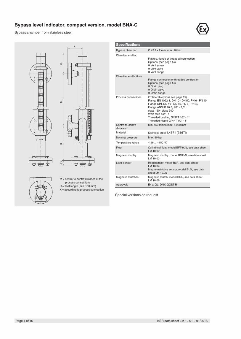
SpecificationsBypass chamber Ø 42.2 x 2 mm, max. 40 bar
Chamber end topFlat top, flange or threaded connectionOptions: (see page 14) Vent screw Vent valve Vent flange
Chamber end bottomFlange connection or threaded connectionOptions: (see page 14) Drain plug Drain valve Drain flange
Process connections 2 x lateral (options see page 15)Flange EN 1092-1, DN 10 - DN 50, PN 6 - PN 40Flange DIN, DN 10 - DN 50, PN 6 - PN 40Flange ANSI B 16.5, 1/2" - 2,5", class 150 - class 300Weld stub 1/2" - 1"Threaded bushing G/NPT 1/2" - 1"Threaded nipple G/NPT 1/2" - 1"
Centre-to-centre distance
Min. 150 mm to max. 5,000 mm
Material Stainless steel 1.4571 (316Ti)Nominal pressure Max. 40 bar
Temperature range -196 ... +150 °C
Float Cylindrical float, model BFT-H32, see data sheet LM 10.02
Magnetic display Magnetic display; model BMD-S; see data sheet LM 10.03
Level sensor Reed sensor, model BLR, see data sheet LM 10.04Magnetostrictive sensor, model BLM, see data sheet LM 10.05
Magnetic switches Magnetic switch, model BGU, see data sheet LM 10.06
Approvals Ex c, GL, DNV, GOST-R
~25
70
X
M...
U...
Bypass level indicator, compact version, model BNA-CBypass chamber from stainless steel
M = centre-to-centre distance of the process connections
U = float length (min. 150 mm)X = according to process connection
Special versions on request
Page 5 of 16KSR data sheet LM 10.01 ∙ 01/2015
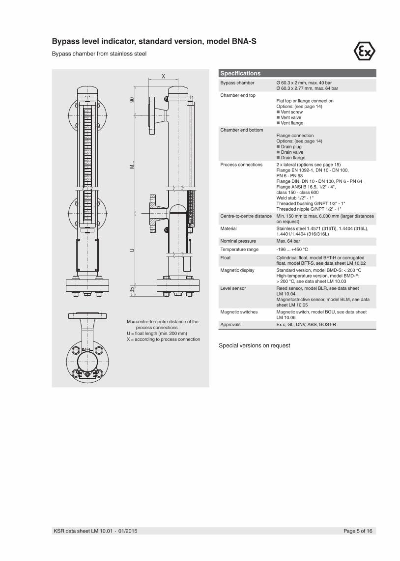
SpecificationsBypass chamber Ø 60.3 x 2 mm, max. 40 bar
Ø 60.3 x 2.77 mm, max. 64 barChamber end top
Flat top or flange connectionOptions: (see page 14) Vent screw Vent valve Vent flange
Chamber end bottomFlange connectionOptions: (see page 14) Drain plug Drain valve Drain flange
Process connections 2 x lateral (options see page 15)Flange EN 1092-1, DN 10 - DN 100, PN 6 - PN 63Flange DIN, DN 10 - DN 100, PN 6 - PN 64Flange ANSI B 16.5, 1/2" - 4", class 150 - class 600Weld stub 1/2" - 1"Threaded bushing G/NPT 1/2" - 1"Threaded nipple G/NPT 1/2" - 1"
Centre-to-centre distance Min. 150 mm to max. 6,000 mm (larger distances on request)
Material Stainless steel 1.4571 (316Ti), 1.4404 (316L), 1.4401/1.4404 (316/316L)
Nominal pressure Max. 64 bar
Temperature range -196 ... +450 °C
Float Cylindrical float, model BFT-H or corrugated float, model BFT-S, see data sheet LM 10.02
Magnetic display Standard version, model BMD-S: < 200 °CHigh-temperature version, model BMD-F: > 200 °C, see data sheet LM 10.03
Level sensor Reed sensor, model BLR, see data sheet LM 10.04Magnetostrictive sensor, model BLM, see data sheet LM 10.05
Magnetic switches Magnetic switch, model BGU, see data sheet LM 10.06
Approvals Ex c, GL, DNV, ABS, GOST-R
Bypass level indicator, standard version, model BNA-SBypass chamber from stainless steel
M = centre-to-centre distance of the process connections
U = float length (min. 200 mm)X = according to process connection
90
X
~35
M...
U
Special versions on request
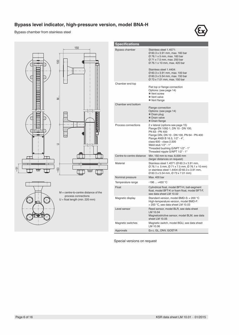
Bypass level indicator, high-pressure version, model BNA-HBypass chamber from stainless steel
150
UM.
..10
0~6
3
~51
Page 6 of 16 KSR data sheet LM 10.01 ∙ 01/2015
M = centre-to-centre distance of the process connections
U = float length (min. 220 mm)
SpecificationsBypass chamber Stainless steel 1.4571:
Ø 60.3 x 3.91 mm, max. 160 barØ 76.1 x 5 mm, max. 160 barØ 71 x 7.5 mm, max. 250 barØ 76.1 x 10 mm, max. 420 bar
Stainless steel 1.4404:Ø 60.3 x 3.91 mm, max. 100 barØ 60.3 x 5.54 mm, max. 150 barØ 73 x 7.01 mm, max. 150 bar
Chamber end topFlat top or flange connectionOptions: (see page 14) Vent screw Vent valve Vent flange
Chamber end bottomFlange connectionOptions: (see page 14) Drain plug Drain valve Drain flange
Process connections 2 x lateral (options see page 15)Flange EN 1092-1, DN 10 - DN 100, PN 63 - PN 400Flange DIN, DN 10 - DN 100, PN 64 - PN 400Flange ANSI B 16.5, 1/2" - 4", class 600 - class 2,500Weld stub 1/2" - 1"Threaded bushing G/NPT 1/2" - 1"Threaded nipple G/NPT 1/2" - 1"
Centre-to-centre distance Min. 150 mm to max. 6,000 mm (larger distances on request)
Material Stainless steel 1.4571 (Ø 60.3 x 3.91 mm, Ø 76.1 x 5 mm, Ø 71 x 7.5 mm, Ø 76.1 x 10 mm) or stainless steel 1.4404 (Ø 60.3 x 3.91 mm, Ø 60.3 x 5.54 mm, Ø 73 x 7.01 mm)
Nominal pressure Max. 400 bar
Temperature range -196 ... +450 °C
Float Cylindrical float, model BFT-H, ball-segment float, model BFT-K or foam float, model BFT-F, see data sheet LM 10.02
Magnetic display Standard version, model BMD-S: < 200 °CHigh-temperature version, model BMD-F: > 200 °C, see data sheet LM 10.03
Level sensor Reed sensor, model BLR, see data sheet LM 10.04Magnetostrictive sensor, model BLM, see data sheet LM 10.05
Magnetic switches Magnetic switch, model BGU, see data sheet LM 10.06
Approvals Ex c, GL, DNV, GOST-R
Special versions on request
Page 7 of 16KSR data sheet LM 10.01 ∙ 01/2015
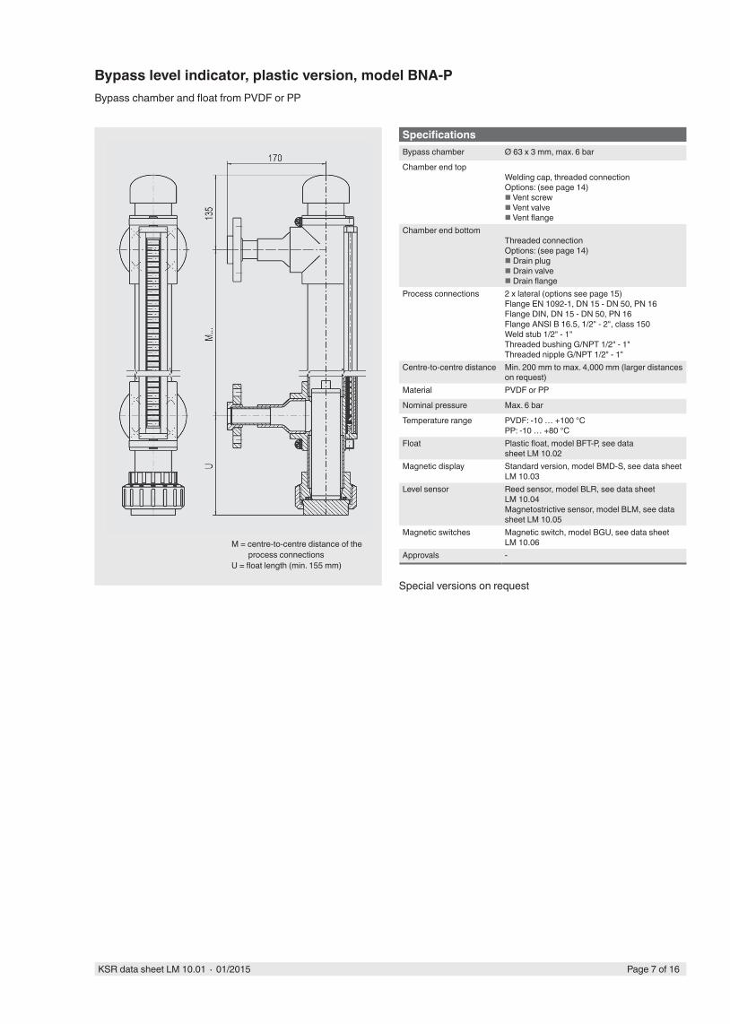
Specifi cationsBypass chamber Ø 63 x 3 mm, max. 6 bar
Chamber end topWelding cap, threaded connectionOptions: (see page 14) Vent screw Vent valve Vent fl ange
Chamber end bottomThreaded connectionOptions: (see page 14) Drain plug Drain valve Drain fl ange
Process connections 2 x lateral (options see page 15)Flange EN 1092-1, DN 15 - DN 50, PN 16Flange DIN, DN 15 - DN 50, PN 16Flange ANSI B 16.5, 1/2" - 2", class 150Weld stub 1/2" - 1"Threaded bushing G/NPT 1/2" - 1"Threaded nipple G/NPT 1/2" - 1"
Centre-to-centre distance Min. 200 mm to max. 4,000 mm (larger distances on request)
Material PVDF or PP
Nominal pressure Max. 6 bar
Temperature range PVDF: -10 … +100 °CPP: -10 … +80 °C
Float Plastic float, model BFT-P, see data sheet LM 10.02
Magnetic display Standard version, model BMD-S, see data sheet LM 10.03
Level sensor Reed sensor, model BLR, see data sheet LM 10.04Magnetostrictive sensor, model BLM, see data sheet LM 10.05
Magnetic switches Magnetic switch, model BGU, see data sheet LM 10.06
Approvals -M = centre-to-centre distance of the
process connectionsU = fl oat length (min. 155 mm)
Bypass level indicator, plastic version, model BNA-PBypass chamber and fl oat from PVDF or PP
Special versions on request
Page 8 of 16 KSR data sheet LM 10.01 ∙ 01/2015
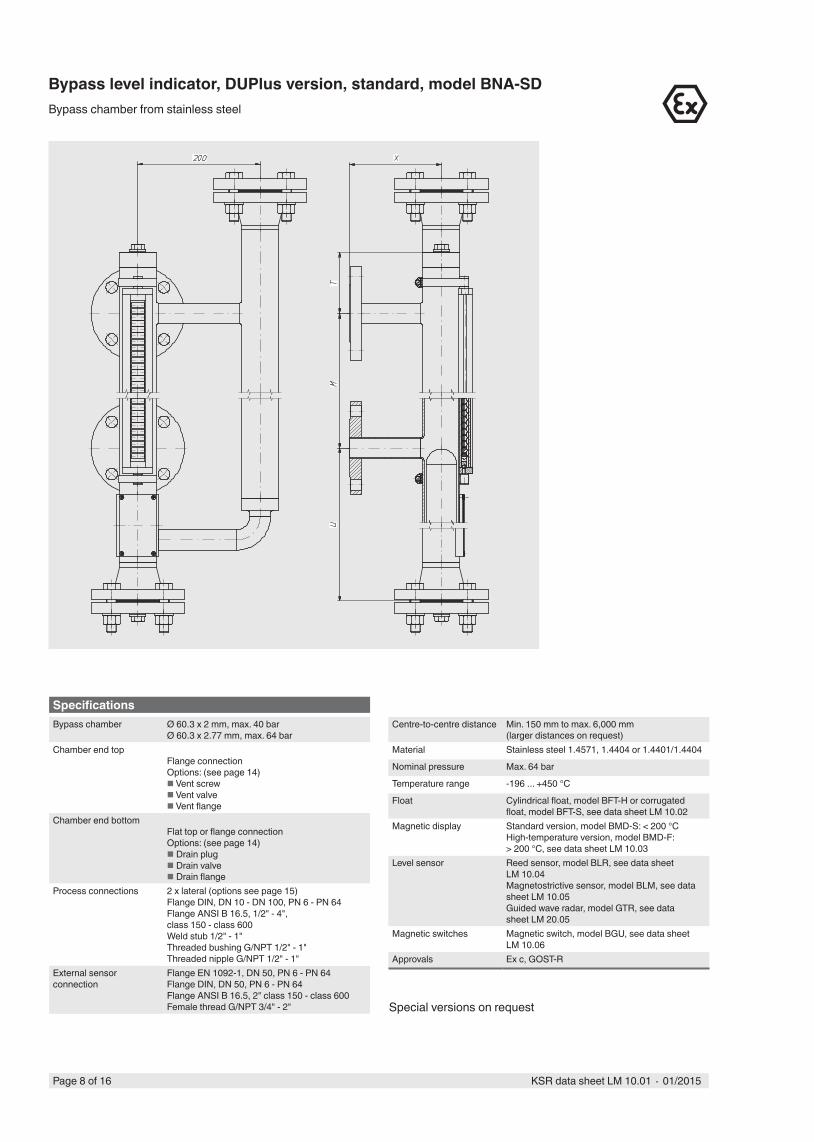
Bypass level indicator, DUPlus version, standard, model BNA-SDBypass chamber from stainless steel
SpecificationsBypass chamber Ø 60.3 x 2 mm, max. 40 bar
Ø 60.3 x 2.77 mm, max. 64 barChamber end top
Flange connectionOptions: (see page 14) Vent screw Vent valve Vent flange
Chamber end bottomFlat top or flange connectionOptions: (see page 14) Drain plug Drain valve Drain flange
Process connections 2 x lateral (options see page 15)Flange DIN, DN 10 - DN 100, PN 6 - PN 64Flange ANSI B 16.5, 1/2" - 4", class 150 - class 600Weld stub 1/2" - 1"Threaded bushing G/NPT 1/2" - 1"Threaded nipple G/NPT 1/2" - 1"
External sensor connection
Flange EN 1092-1, DN 50, PN 6 - PN 64Flange DIN, DN 50, PN 6 - PN 64Flange ANSI B 16.5, 2" class 150 - class 600Female thread G/NPT 3/4" - 2"
Centre-to-centre distance Min. 150 mm to max. 6,000 mm (larger distances on request)
Material Stainless steel 1.4571, 1.4404 or 1.4401/1.4404
Nominal pressure Max. 64 bar
Temperature range -196 ... +450 °C
Float Cylindrical float, model BFT-H or corrugated float, model BFT-S, see data sheet LM 10.02
Magnetic display Standard version, model BMD-S: < 200 °CHigh-temperature version, model BMD-F: > 200 °C, see data sheet LM 10.03
Level sensor Reed sensor, model BLR, see data sheet LM 10.04Magnetostrictive sensor, model BLM, see data sheet LM 10.05Guided wave radar, model GTR, see data sheet LM 20.05
Magnetic switches Magnetic switch, model BGU, see data sheet LM 10.06
Approvals Ex c, GOST-R
Special versions on request
Page 9 of 16KSR data sheet LM 10.01 ∙ 01/2015
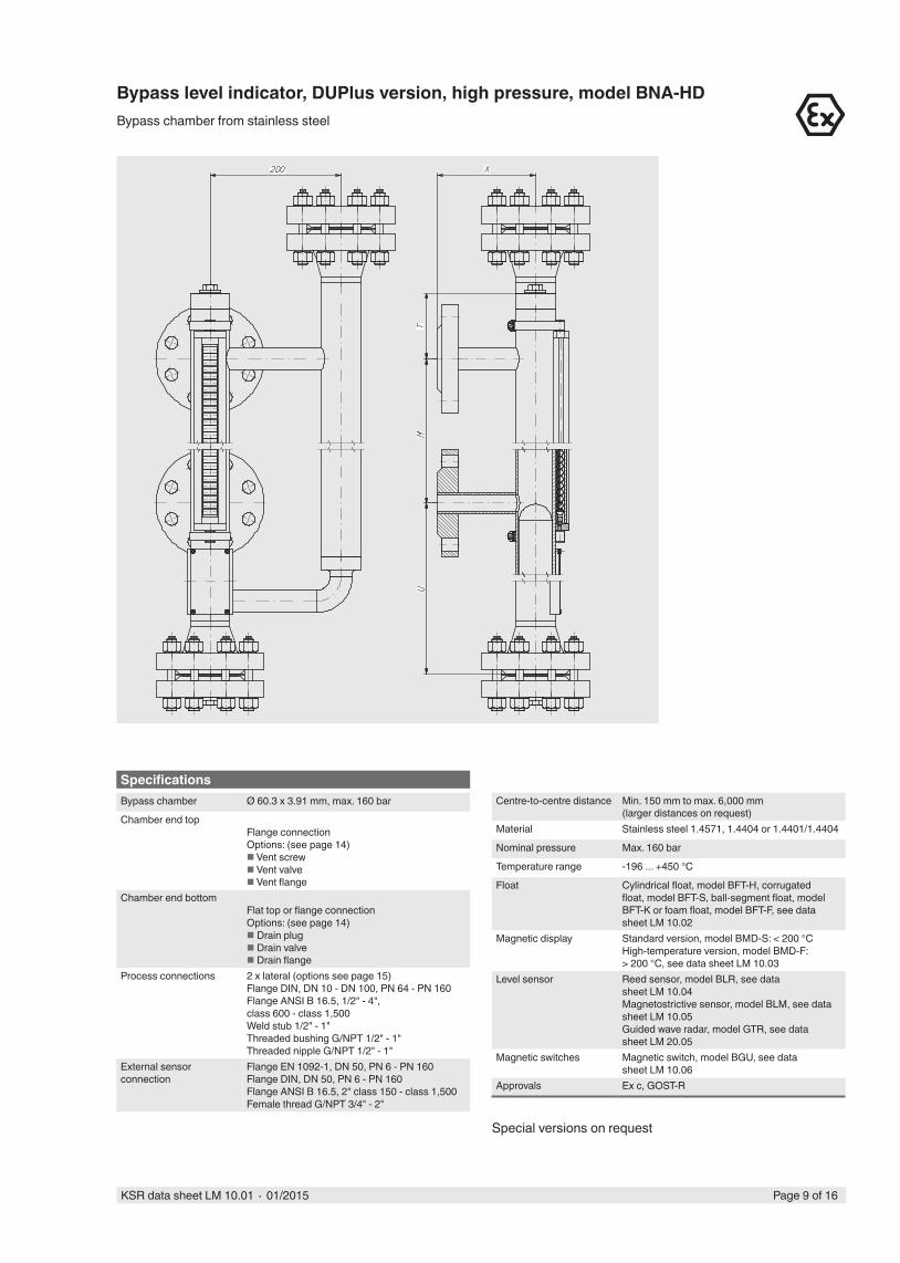
Bypass level indicator, DUPlus version, high pressure, model BNA-HDBypass chamber from stainless steel
SpecificationsBypass chamber Ø 60.3 x 3.91 mm, max. 160 bar
Chamber end topFlange connectionOptions: (see page 14) Vent screw Vent valve Vent flange
Chamber end bottomFlat top or flange connectionOptions: (see page 14) Drain plug Drain valve Drain flange
Process connections 2 x lateral (options see page 15)Flange DIN, DN 10 - DN 100, PN 64 - PN 160Flange ANSI B 16.5, 1/2" - 4", class 600 - class 1,500Weld stub 1/2" - 1"Threaded bushing G/NPT 1/2" - 1"Threaded nipple G/NPT 1/2" - 1"
External sensor connection
Flange EN 1092-1, DN 50, PN 6 - PN 160Flange DIN, DN 50, PN 6 - PN 160Flange ANSI B 16.5, 2" class 150 - class 1,500Female thread G/NPT 3/4" - 2"
Centre-to-centre distance Min. 150 mm to max. 6,000 mm (larger distances on request)
Material Stainless steel 1.4571, 1.4404 or 1.4401/1.4404
Nominal pressure Max. 160 bar
Temperature range -196 ... +450 °C
Float Cylindrical float, model BFT-H, corrugated float, model BFT-S, ball-segment float, model BFT-K or foam float, model BFT-F, see data sheet LM 10.02
Magnetic display Standard version, model BMD-S: < 200 °CHigh-temperature version, model BMD-F: > 200 °C, see data sheet LM 10.03
Level sensor Reed sensor, model BLR, see data sheet LM 10.04Magnetostrictive sensor, model BLM, see data sheet LM 10.05Guided wave radar, model GTR, see data sheet LM 20.05
Magnetic switches Magnetic switch, model BGU, see data sheet LM 10.06
Approvals Ex c, GOST-R
Special versions on request
Page 10 of 16 KSR data sheet LM 10.01 ∙ 01/2015
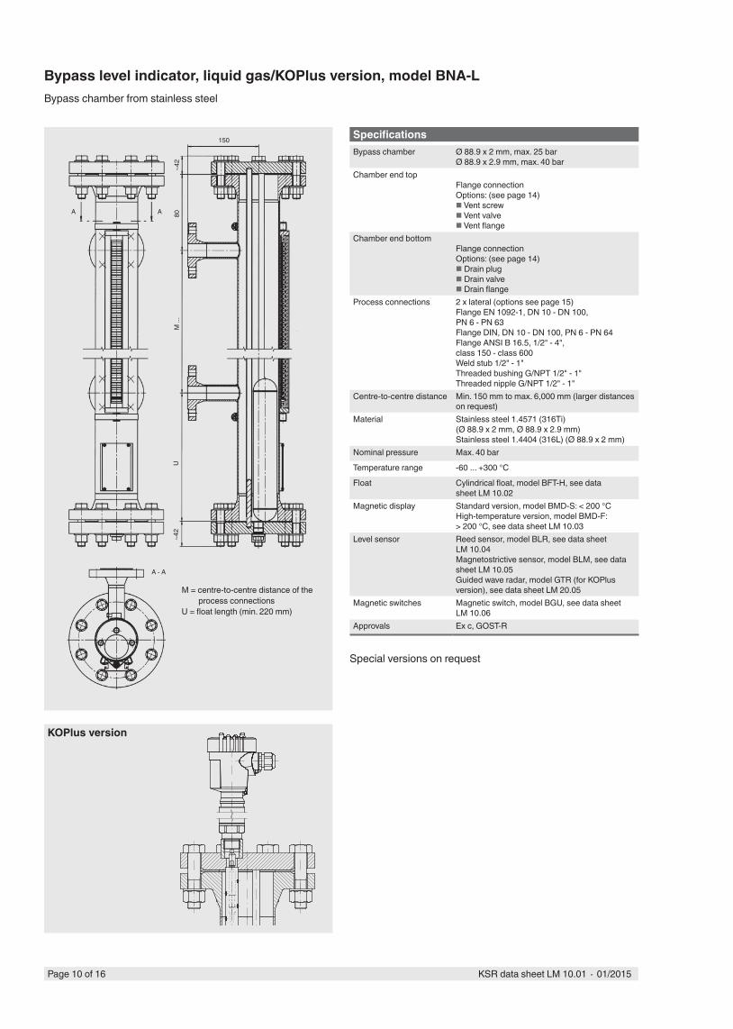
M = centre-to-centre distance of the process connections
U = float length (min. 220 mm)
Bypass level indicator, liquid gas/KOPlus version, model BNA-LBypass chamber from stainless steel
150
~42
UM
...
80A A
A - A
~42
SpecificationsBypass chamber Ø 88.9 x 2 mm, max. 25 bar
Ø 88.9 x 2.9 mm, max. 40 barChamber end top
Flange connectionOptions: (see page 14) Vent screw Vent valve Vent flange
Chamber end bottomFlange connectionOptions: (see page 14) Drain plug Drain valve Drain flange
Process connections 2 x lateral (options see page 15)Flange EN 1092-1, DN 10 - DN 100, PN 6 - PN 63Flange DIN, DN 10 - DN 100, PN 6 - PN 64Flange ANSI B 16.5, 1/2" - 4", class 150 - class 600Weld stub 1/2" - 1"Threaded bushing G/NPT 1/2" - 1"Threaded nipple G/NPT 1/2" - 1"
Centre-to-centre distance Min. 150 mm to max. 6,000 mm (larger distances on request)
Material Stainless steel 1.4571 (316Ti)(Ø 88.9 x 2 mm, Ø 88.9 x 2.9 mm)Stainless steel 1.4404 (316L) (Ø 88.9 x 2 mm)
Nominal pressure Max. 40 bar
Temperature range -60 ... +300 °C
Float Cylindrical float, model BFT-H, see data sheet LM 10.02
Magnetic display Standard version, model BMD-S: < 200 °CHigh-temperature version, model BMD-F: > 200 °C, see data sheet LM 10.03
Level sensor Reed sensor, model BLR, see data sheet LM 10.04Magnetostrictive sensor, model BLM, see data sheet LM 10.05Guided wave radar, model GTR (for KOPlus version), see data sheet LM 20.05
Magnetic switches Magnetic switch, model BGU, see data sheet LM 10.06
Approvals Ex c, GOST-R
Special versions on request
KOPlus version
Page 11 of 16KSR data sheet LM 10.01 ∙ 01/2015
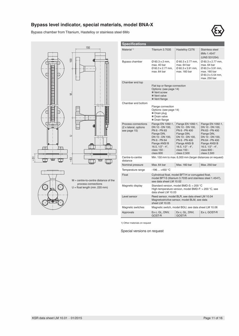
SpecificationsMaterial 1) Titanium 3.7035 Hastelloy C276 Stainless steel
6Mo 1.4547 (UNS S31254)
Bypass chamber Ø 60.3 x 2 mm, max. 40 barØ 60.3 x 2.77 mm, max. 64 bar
Ø 60.3 x 2.77 mm, max. 64 barØ 60.3 x 3.91 mm, max. 160 bar
Ø 60.3 x 2.77 mm, max. 64 barØ 60.3 x 3.91 mm, max. 160 barØ 60.3 x 5.54 mm, max. 250 bar
Chamber end topFlat top or flange connectionOptions: (see page 14) Vent screw Vent valve Vent flange
Chamber end bottomFlange connectionOptions: (see page 14) Drain plug Drain valve Drain flange
Process connections(2 x lateral, options see page 15)
Flange EN 1092-1, DN 10 - DN 100, PN 6 - PN 63Flange DIN, DN 10 - DN 100, PN 6 - PN 64Flange ANSI B 16.5, 1/2" - 4", class 150 - class 600
Flange EN 1092-1, DN 10 - DN 100, PN 6 - PN 400Flange DIN, DN 10 - DN 100, PN 6 - PN 400Flange ANSI B 16.5, 1/2" - 4", class 150 - class 2,500
Flange EN 1092-1, DN 10 - DN 100, PN 63 - PN 400Flange DIN, DN 10 - DN 100, PN 64 - PN 400Flange ANSI B 16.5, 1/2" - 4", class 600 - class 2,500
Centre-to-centre distance
Min. 150 mm to max. 6,000 mm (larger distances on request)
Nominal pressure Max. 64 bar Max. 160 bar Max. 250 bar
Temperature range -196 ... +450 °C
Float Cylindrical float, model BFT-H or corrugated float, model BFT-S (titanium 3.7035 and stainless steel 1.4547), see data sheet LM 10.02
Magnetic display Standard version, model BMD-S: < 200 °CHigh-temperature version, model BMD-F: > 200 °C, see data sheet LM 10.03
Level sensor Reed sensor, model BLR, see data sheet LM 10.04Magnetostrictive sensor, model BLM, see data sheet LM 10.05
Magnetic switches Magnetic switch, model BGU, see data sheet LM 10.06
Approvals Ex c, GL, DNV, GOST-R
Ex c, GL, DNV, GOST-R
Ex c, GOST-R
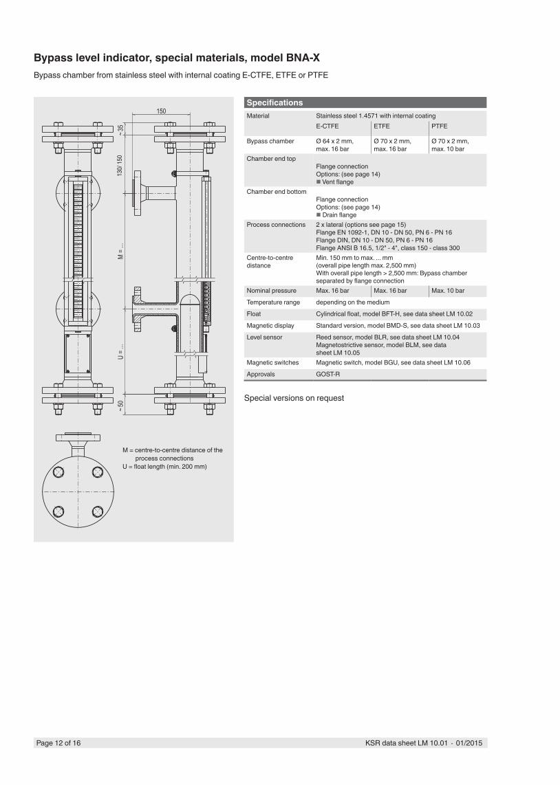
Bypass level indicator, special materials, model BNA-XBypass chamber from Titanium, Hastelloy or stainless steel 6Mo
150
UM.
..10
0~6
3
~51
M = centre-to-centre distance of the process connections
U = float length (min. 220 mm)
1) Other materials on request
Special versions on request
Page 12 of 16 KSR data sheet LM 10.01 ∙ 01/2015
SpecificationsMaterial Stainless steel 1.4571 with internal coating
E-CTFE ETFE PTFE
Bypass chamber Ø 64 x 2 mm, max. 16 bar
Ø 70 x 2 mm, max. 16 bar
Ø 70 x 2 mm, max. 10 bar
Chamber end topFlange connectionOptions: (see page 14) Vent flange
Chamber end bottomFlange connectionOptions: (see page 14) Drain flange
Process connections 2 x lateral (options see page 15)Flange EN 1092-1, DN 10 - DN 50, PN 6 - PN 16Flange DIN, DN 10 - DN 50, PN 6 - PN 16Flange ANSI B 16.5, 1/2" - 4", class 150 - class 300
Centre-to-centre distance
Min. 150 mm to max. ... mm(overall pipe length max. 2,500 mm)With overall pipe length > 2,500 mm: Bypass chamber separated by flange connection
Nominal pressure Max. 16 bar Max. 16 bar Max. 10 bar
Temperature range depending on the medium
Float Cylindrical float, model BFT-H, see data sheet LM 10.02
Magnetic display Standard version, model BMD-S, see data sheet LM 10.03
Level sensor Reed sensor, model BLR, see data sheet LM 10.04Magnetostrictive sensor, model BLM, see data sheet LM 10.05
Magnetic switches Magnetic switch, model BGU, see data sheet LM 10.06
Approvals GOST-R
150~3
515
0~5
0U
= ...
M =
...
M = centre-to-centre distance of the process connections
U = float length (min. 200 mm)
Bypass level indicator, special materials, model BNA-XBypass chamber from stainless steel with internal coating E-CTFE, ETFE or PTFE
Special versions on request
130/
150
Page 13 of 16KSR data sheet LM 10.01 ∙ 01/2015
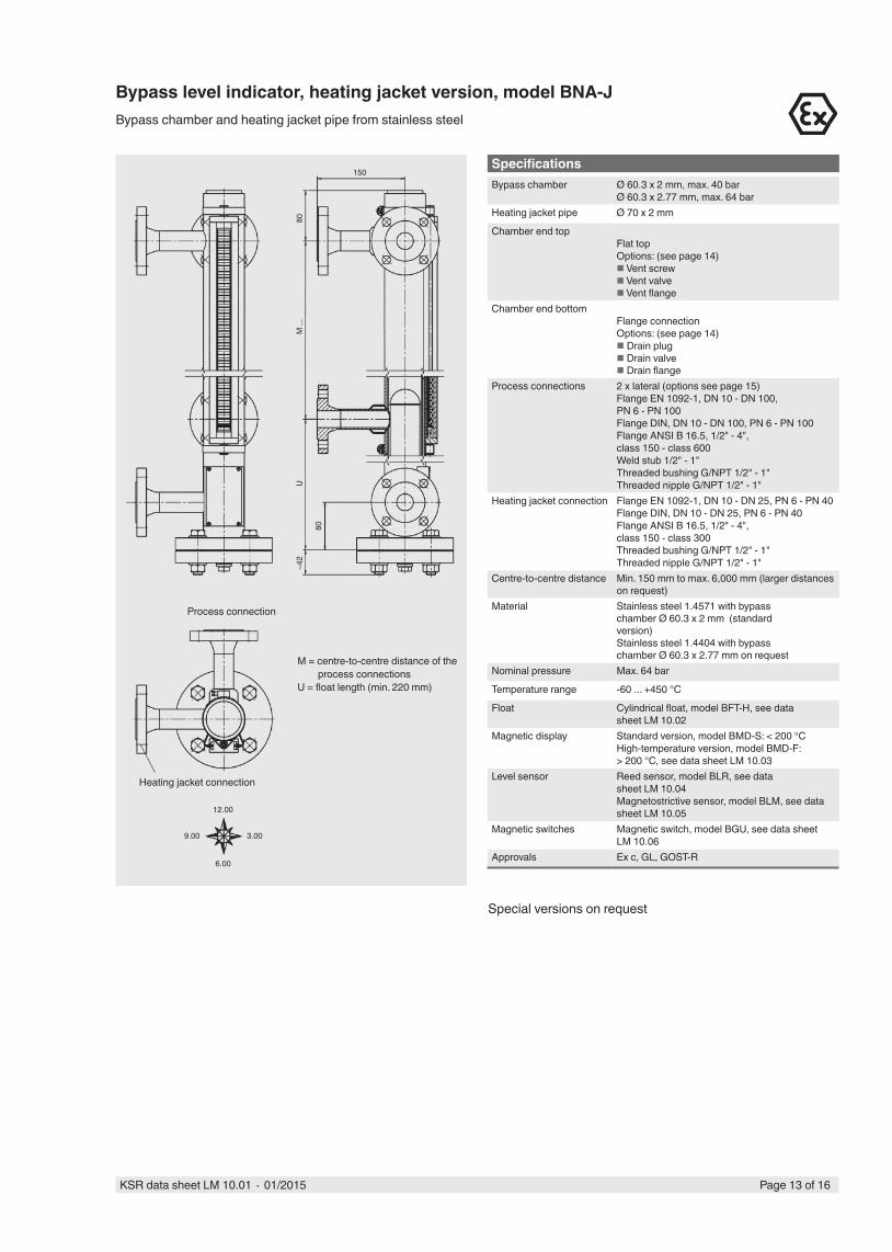
Bypass level indicator, heating jacket version, model BNA-JBypass chamber and heating jacket pipe from stainless steel
M = centre-to-centre distance of the process connections
U = float length (min. 220 mm)
Process connection
Heating jacket connection
12.00
6.00
9.00 3.00
150
~42
UM
...
80
80
SpecificationsBypass chamber Ø 60.3 x 2 mm, max. 40 bar
Ø 60.3 x 2.77 mm, max. 64 barHeating jacket pipe Ø 70 x 2 mm
Chamber end topFlat topOptions: (see page 14) Vent screw Vent valve Vent flange
Chamber end bottomFlange connectionOptions: (see page 14) Drain plug Drain valve Drain flange
Process connections 2 x lateral (options see page 15)Flange EN 1092-1, DN 10 - DN 100, PN 6 - PN 100Flange DIN, DN 10 - DN 100, PN 6 - PN 100Flange ANSI B 16.5, 1/2" - 4", class 150 - class 600Weld stub 1/2" - 1"Threaded bushing G/NPT 1/2" - 1"Threaded nipple G/NPT 1/2" - 1"
Heating jacket connection Flange EN 1092-1, DN 10 - DN 25, PN 6 - PN 40Flange DIN, DN 10 - DN 25, PN 6 - PN 40Flange ANSI B 16.5, 1/2" - 4", class 150 - class 300Threaded bushing G/NPT 1/2" - 1"Threaded nipple G/NPT 1/2" - 1"
Centre-to-centre distance Min. 150 mm to max. 6,000 mm (larger distances on request)
Material Stainless steel 1.4571 with bypass chamber Ø 60.3 x 2 mm (standard version)Stainless steel 1.4404 with bypass chamber Ø 60.3 x 2.77 mm on request
Nominal pressure Max. 64 bar
Temperature range -60 ... +450 °C
Float Cylindrical float, model BFT-H, see data sheet LM 10.02
Magnetic display Standard version, model BMD-S: < 200 °CHigh-temperature version, model BMD-F: > 200 °C, see data sheet LM 10.03
Level sensor Reed sensor, model BLR, see data sheet LM 10.04Magnetostrictive sensor, model BLM, see data sheet LM 10.05
Magnetic switches Magnetic switch, model BGU, see data sheet LM 10.06
Approvals Ex c, GL, GOST-R
Special versions on request
Page 14 of 16 KSR data sheet LM 10.01 ∙ 01/2015
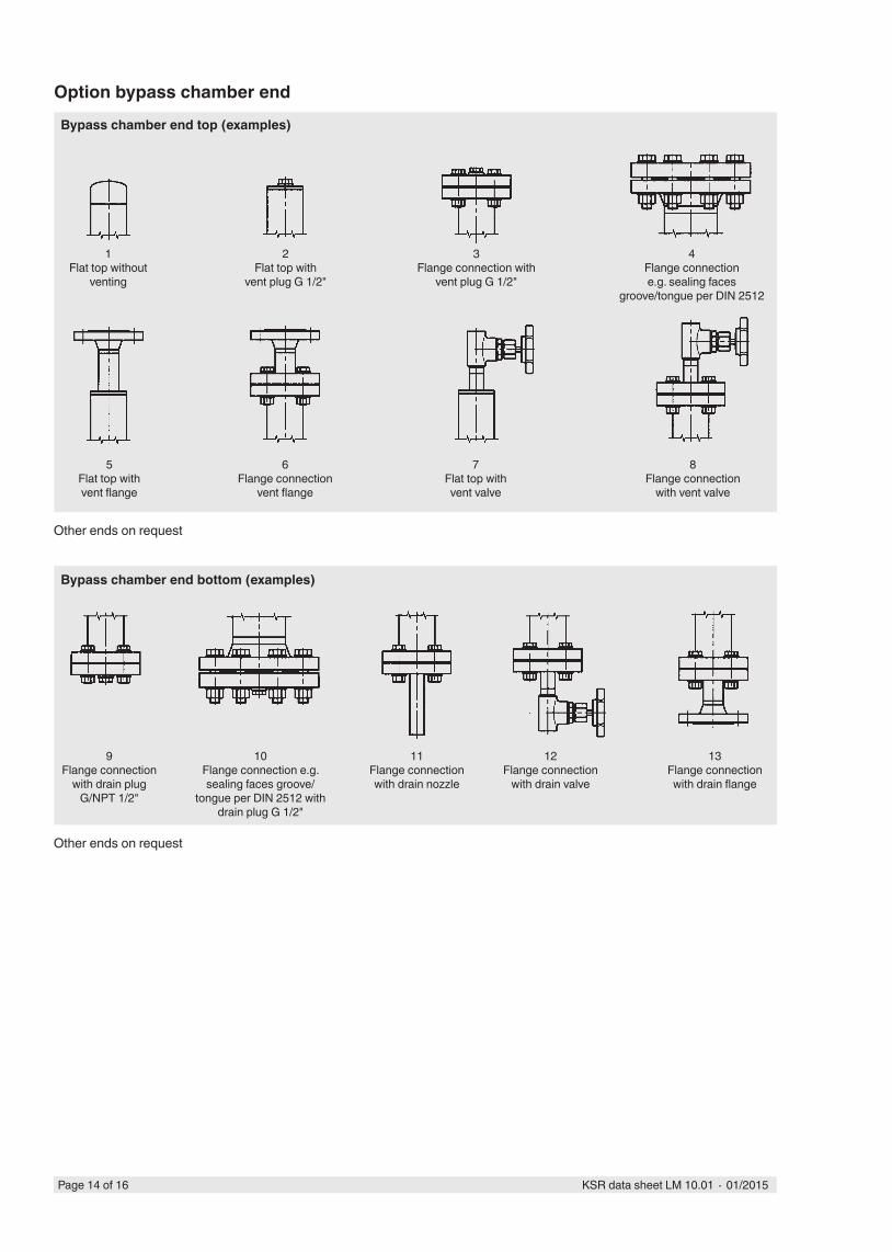
Bypass chamber end top (examples)
1Flat top without
venting
Bypass chamber end bottom (examples)
2Flat top with
vent plug G 1/2"
3Flange connection with
vent plug G 1/2"
4Flange connectione.g. sealing faces
groove/tongue per DIN 2512
5Flat top withvent flange
6Flange connection
vent flange
7Flat top with vent valve
8Flange connection
with vent valve
9Flange connection
with drain plug G/NPT 1/2"
10Flange connection e.g. sealing faces groove/
tongue per DIN 2512 with drain plug G 1/2"
11Flange connection with drain nozzle
12Flange connection
with drain valve
13Flange connection with drain flange
Option bypass chamber end
Other ends on request
Other ends on request
Page 15 of 16KSR data sheet LM 10.01 ∙ 01/2015
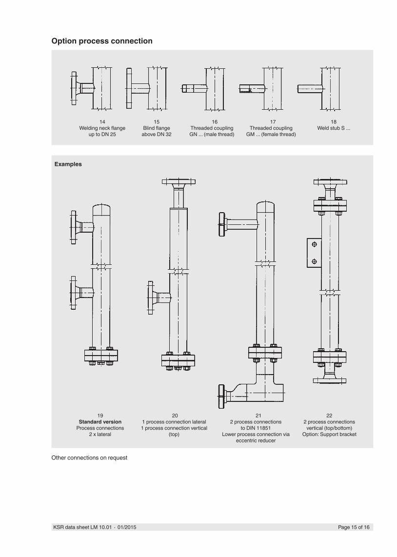
14Welding neck flange
up to DN 25
15Blind flange
above DN 32
16Threaded coupling GN ... (male thread)
17Threaded coupling
GM ... (female thread)
18Weld stub S ...
201 process connection lateral 1 process connection vertical
(top)
212 process connections
to DIN 11851 Lower process connection via
eccentric reducer
222 process connections
vertical (top/bottom)Option: Support bracket
19Standard version
Process connections 2 x lateral
Option process connection
Examples
Other connections on request
KSR KUEBLER Niveau-Messtechnik AGHeinrich-Kuebler-Platz 169439 Zwingenberg/GermanyTel. +49 6263 87-0Fax +49 6263 [email protected]
Ordering informationModel / Approval / Material / Process specifi cations (operating temperature and pressure, density) / Process connection / Centre-to-centre distance M ...
Detailed information on fl oats, magnetic displays, sensors (reed chains and magnetostrictive) and magnetic switches can be found in the following data sheets:
■ Float, model BFT; see data sheet LM 10.02 ■ Magnetic display; model BMD; see data sheet LM 10.03 ■ Reed sensor; model BLR; see data sheet LM 10.04 ■ Magnetostrictive sensor; model BLM; see data sheet LM 10.05 ■ Guided wave radar, model GTR, see data sheet LM 20.05 ■ Magnetic switch; model BGU; see data sheet LM 10.06
CE conformity
Pressure equipment directive97/23/EC, pressure accessory
ATEX directive (option)94/9/EC, ignition protection type Ex c, zone 0/1, gas
Approvals
■ GL, ships, shipbuilding, off shore, Germany ■ DNV, ships, shipbuilding, off shore, Norway ■ ABS, ships, shipbuilding, off shore, USA ■ GOST, national standard for Russia, Kazakhstan and
Belarus
Approvals and certifi cates, see website
© 2014 KSR KUEBLER Niveau-Messtechnik AG, all rights reserved.The specifi cations given in this document represent the state of engineering at the time of publishing.We reserve the right to make modifi cations to the specifi cations and materials.
KSR data sheet LM 10.01 ∙ 01/2015Page 16 of 16
01/2
015
EN


![Water level indicator [autosaved]](https://img.pdfslide.net/doc/110x75/587996bd1a28ab95318b6a91/water-level-indicator-autosaved.jpg)