Embed Size (px)
Citation preview
Computer Networks: A Systems Approach, 5eLarry L. Peterson and Bruce S. Davie
C 2
Getting Connected
Copyright © 2010, Elsevier Inc. All rights Reserved
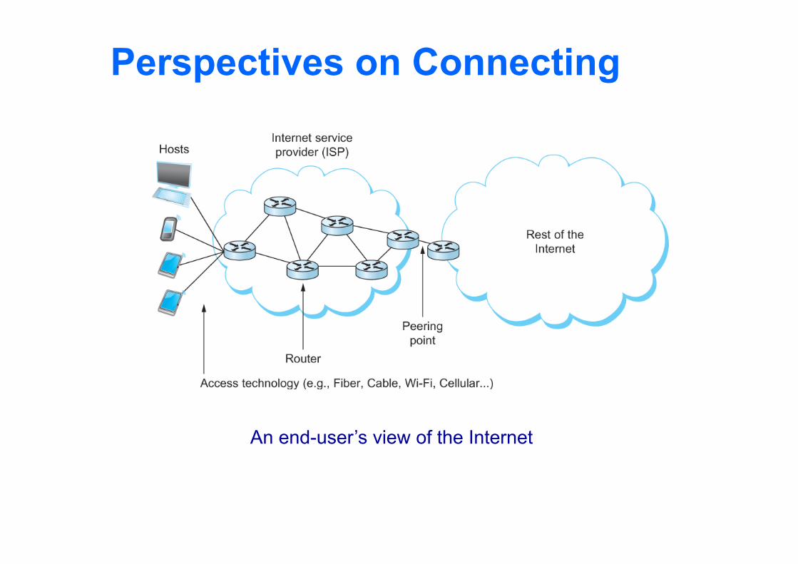
Perspectives on Connecting
An end-user’s view of the Internet
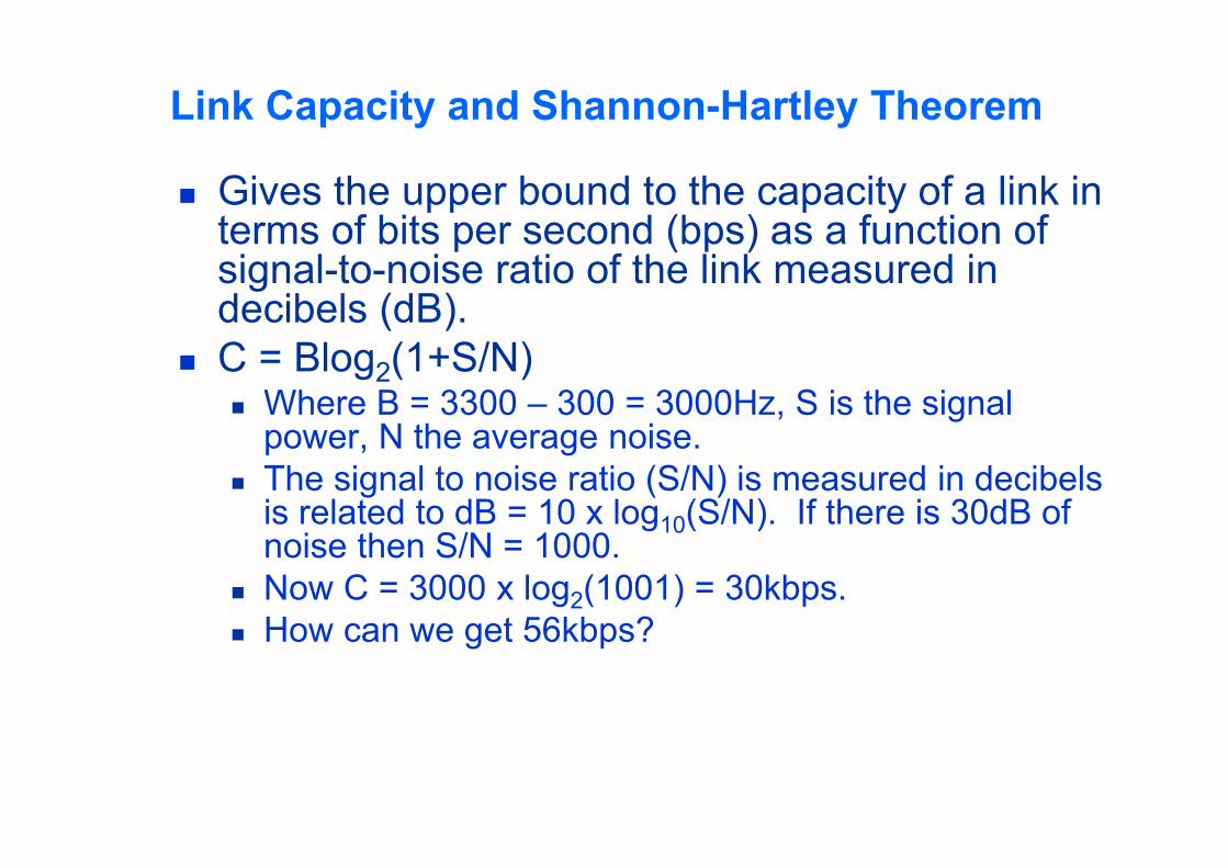
Link Capacity and Shannon-Hartley Theorem
Gives the upper bound to the capacity of a link in terms of bits per second (bps) as a function of signal-to-noise ratio of the link measured in decibels (dB).
C = Blog2(1+S/N) Where B = 3300 – 300 = 3000Hz, S is the signal
power, N the average noise. The signal to noise ratio (S/N) is measured in decibels
is related to dB = 10 x log10(S/N). If there is 30dB of noise then S/N = 1000.
Now C = 3000 x log2(1001) = 30kbps. How can we get 56kbps?
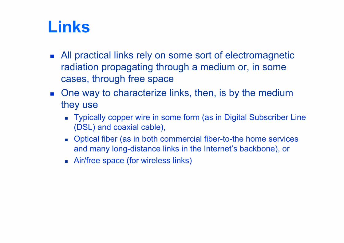
Links All practical links rely on some sort of electromagnetic
radiation propagating through a medium or, in some cases, through free space
One way to characterize links, then, is by the medium they use Typically copper wire in some form (as in Digital Subscriber Line
(DSL) and coaxial cable), Optical fiber (as in both commercial fiber-to-the home services
and many long-distance links in the Internet’s backbone), or Air/free space (for wireless links)
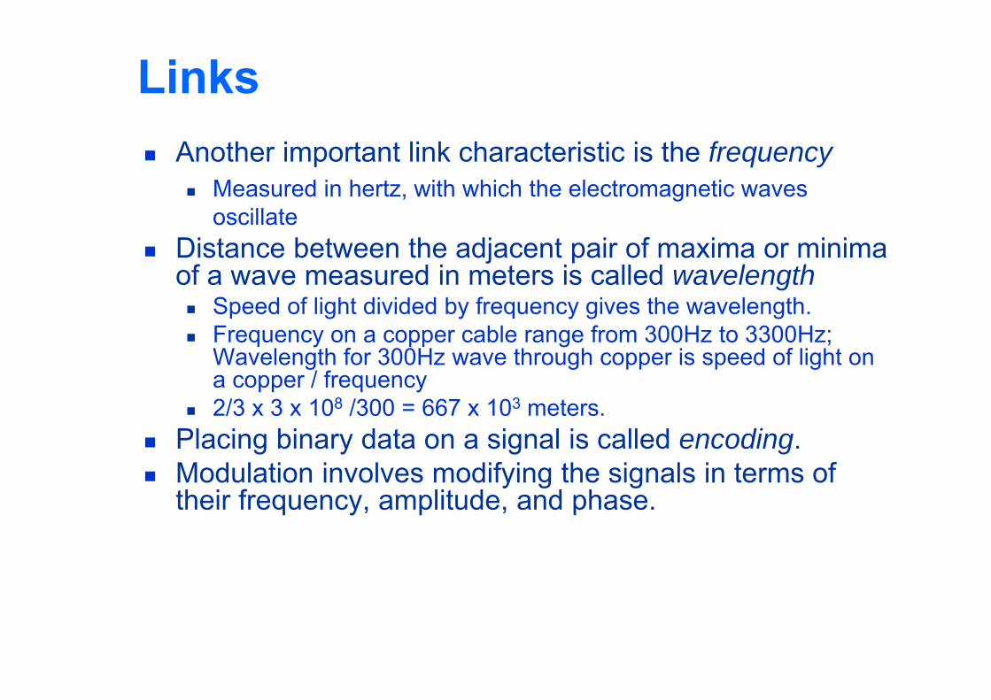
Links Another important link characteristic is the frequency
Measured in hertz, with which the electromagnetic waves oscillate
Distance between the adjacent pair of maxima or minima of a wave measured in meters is called wavelength Speed of light divided by frequency gives the wavelength. Frequency on a copper cable range from 300Hz to 3300Hz;
Wavelength for 300Hz wave through copper is speed of light on a copper / frequency
2/3 x 3 x 108 /300 = 667 x 103 meters. Placing binary data on a signal is called encoding. Modulation involves modifying the signals in terms of
their frequency, amplitude, and phase.
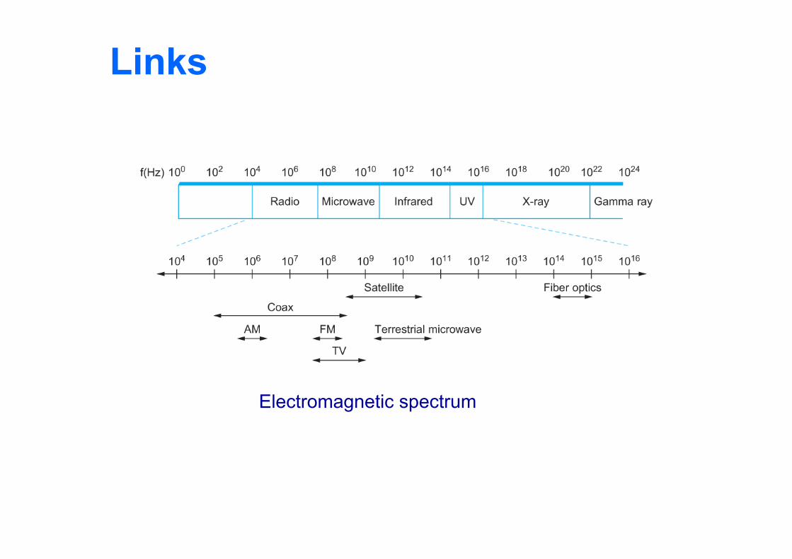
Links
Electromagnetic spectrum
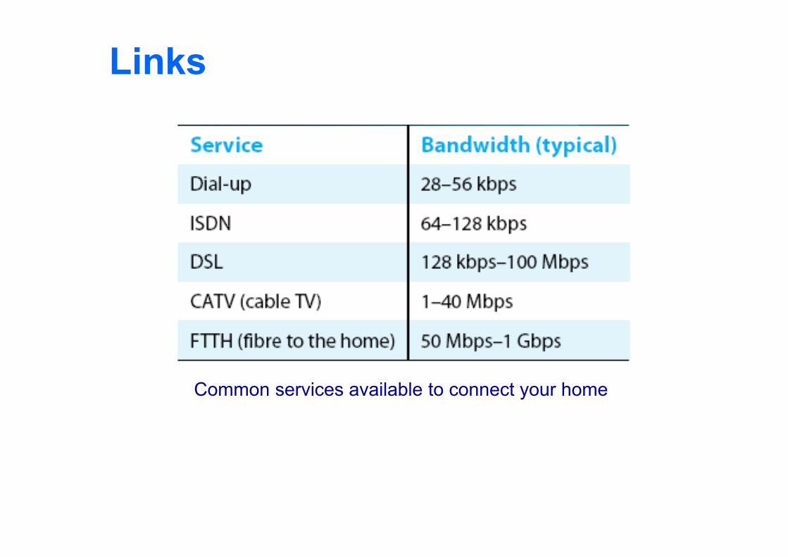
Links
Common services available to connect your home
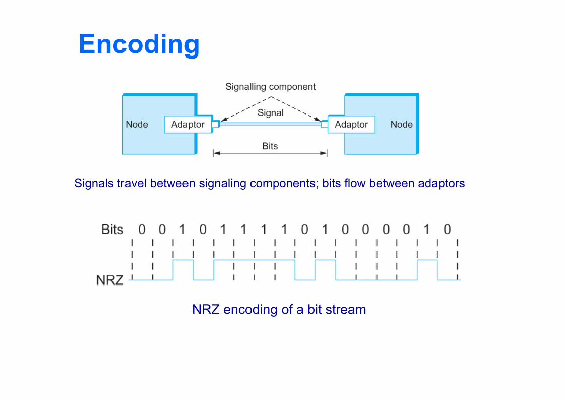
Encoding
Signals travel between signaling components; bits flow between adaptors
NRZ encoding of a bit stream
Encoding
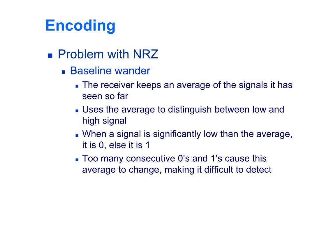
Problem with NRZ Baseline wander
The receiver keeps an average of the signals it has seen so far
Uses the average to distinguish between low and high signal
When a signal is significantly low than the average, it is 0, else it is 1
Too many consecutive 0’s and 1’s cause this average to change, making it difficult to detect
Encoding
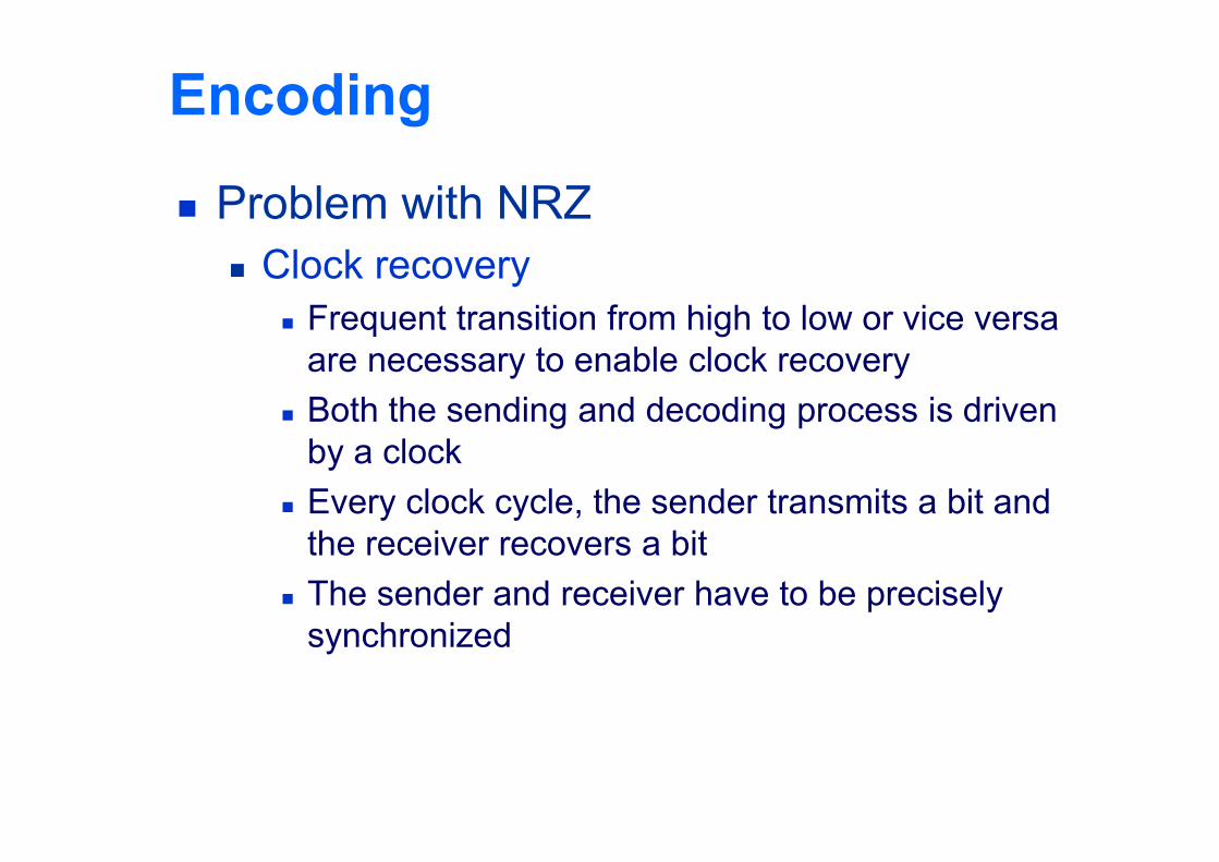
Problem with NRZ Clock recovery
Frequent transition from high to low or vice versa are necessary to enable clock recovery
Both the sending and decoding process is driven by a clock
Every clock cycle, the sender transmits a bit and the receiver recovers a bit
The sender and receiver have to be precisely synchronized
Encoding
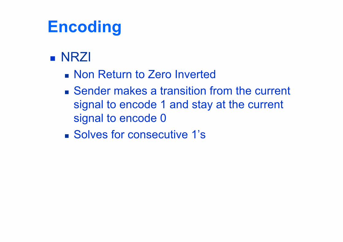
NRZI Non Return to Zero Inverted Sender makes a transition from the current
signal to encode 1 and stay at the current signal to encode 0
Solves for consecutive 1’s
Encoding
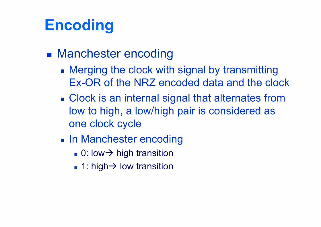
Manchester encoding Merging the clock with signal by transmitting
Ex-OR of the NRZ encoded data and the clock Clock is an internal signal that alternates from
low to high, a low/high pair is considered as one clock cycle
In Manchester encoding 0: low high transition 1: high low transition
Encoding
Problem with Manchester encoding Doubles the rate at which the signal
transitions are made on the link Which means the receiver has half of the time to
detect each pulse of the signal The rate at which the signal changes is called
the link’s baud rate In Manchester the bit rate is half the baud rate
Encoding
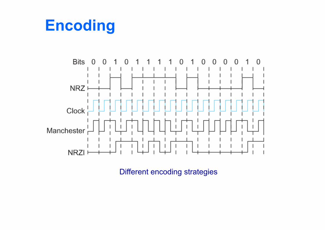
Different encoding strategies
Encoding
4B/5B encoding Insert extra bits into bit stream so as to break up the
long sequence of 0’s and 1’s Every 4-bits of actual data are encoded in a 5- bit
code that is transmitted to the receiver 5-bit codes are selected in such a way that each one
has no more than one leading 0(zero) and no more than two trailing 0’s.
No pair of 5-bit codes results in more than three consecutive 0’s
Encoding
4B/5B encoding
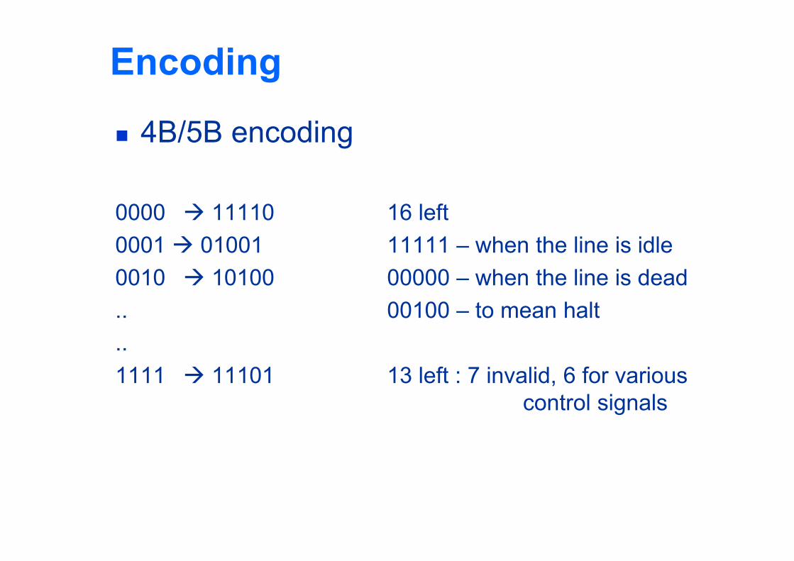
0000 11110 16 left0001 01001 11111 – when the line is idle0010 10100 00000 – when the line is dead.. 00100 – to mean halt..1111 11101 13 left : 7 invalid, 6 for various
control signals
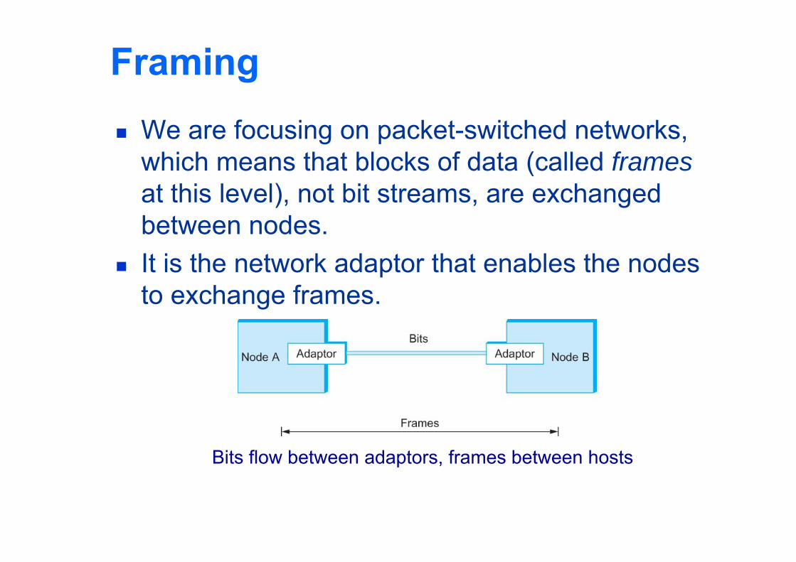
Framing We are focusing on packet-switched networks,
which means that blocks of data (called framesat this level), not bit streams, are exchanged between nodes.
It is the network adaptor that enables the nodes to exchange frames.
Bits flow between adaptors, frames between hosts
Framing When node A wishes to transmit a frame to node
B, it tells its adaptor to transmit a frame from the node’s memory. This results in a sequence of bits being sent over the link.
The adaptor on node B then collects together the sequence of bits arriving on the link and deposits the corresponding frame in B’s memory.
Recognizing exactly what set of bits constitute a frame—that is, determining where the frame begins and ends—is the central challenge faced by the adaptor
Framing Byte-oriented Protocols
To view each frame as a collection of bytes (characters) rather than bits
BISYNC (Binary Synchronous Communication) Protocol Developed by IBM (late 1960)
DDCMP (Digital Data Communication Protocol) Used in DECNet
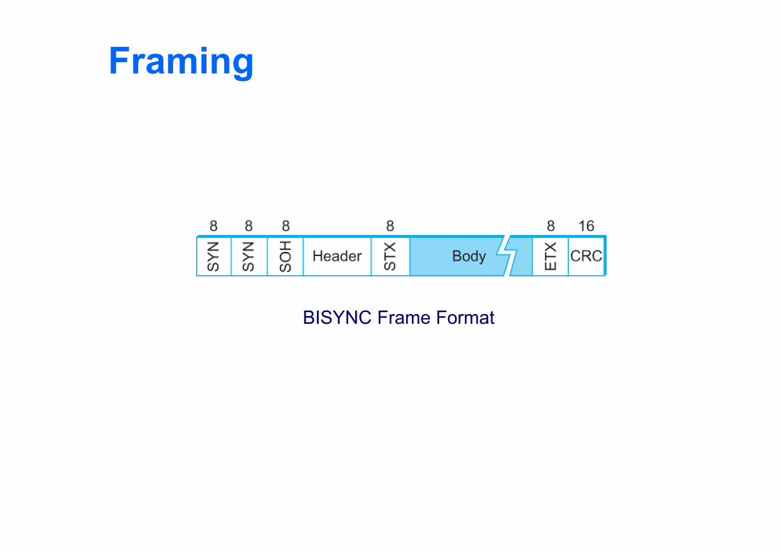
Framing BISYNC – sentinel approach
Frames transmitted beginning with leftmost field Beginning of a frame is denoted by sending a special
SYN (synchronize) character Data portion of the frame is contained between
special sentinel character STX (start of text) and ETX (end of text)
SOH : Start of Header DLE : Data Link Escape CRC: Cyclic Redundancy Check
Framing
BISYNC Frame Format
Framing
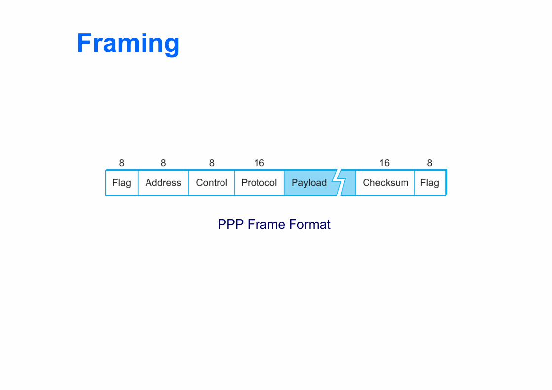
Recent PPP which is commonly run over Internet links uses sentinel approach Special start of text character denoted as Flag
0 1 1 1 1 1 1 0 Address, control : default numbers Protocol for demux : IP / IPX Payload : negotiated (1500 bytes) Checksum : for error detection
Framing
PPP Frame Format
Framing
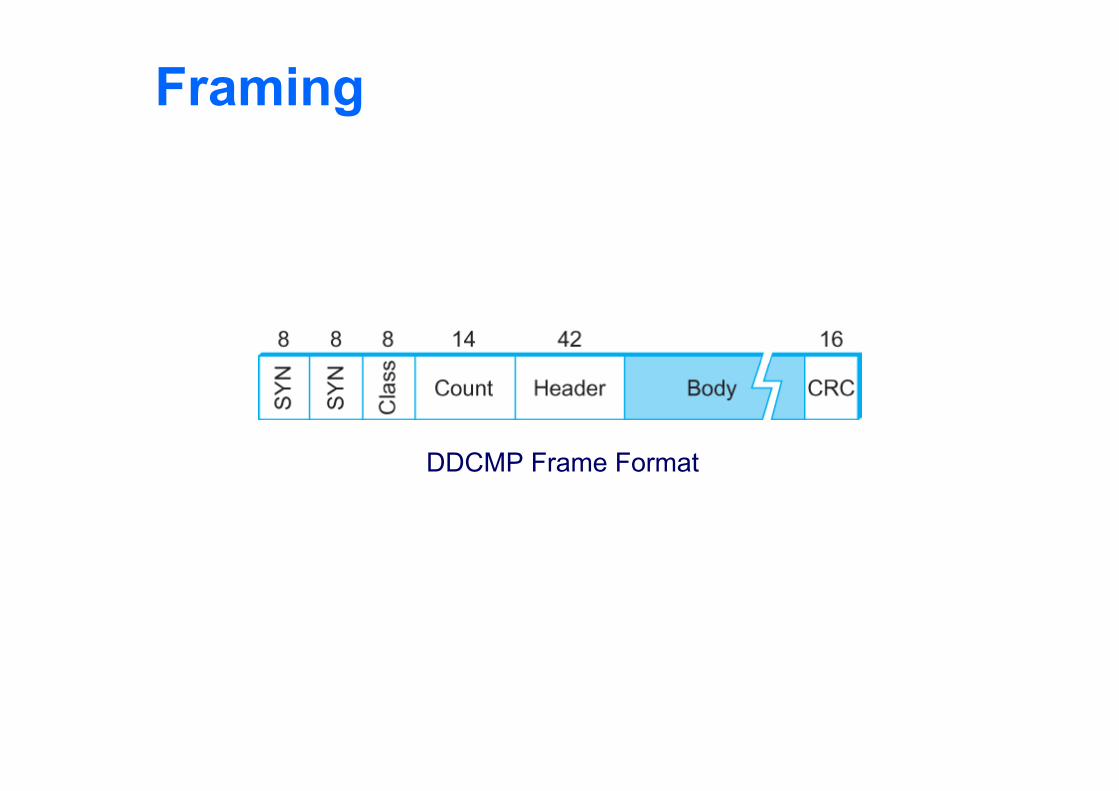
Byte-counting approach DDCMP count : how many bytes are contained in the
frame body If count is corrupted
Framing error
Framing
DDCMP Frame Format
Framing
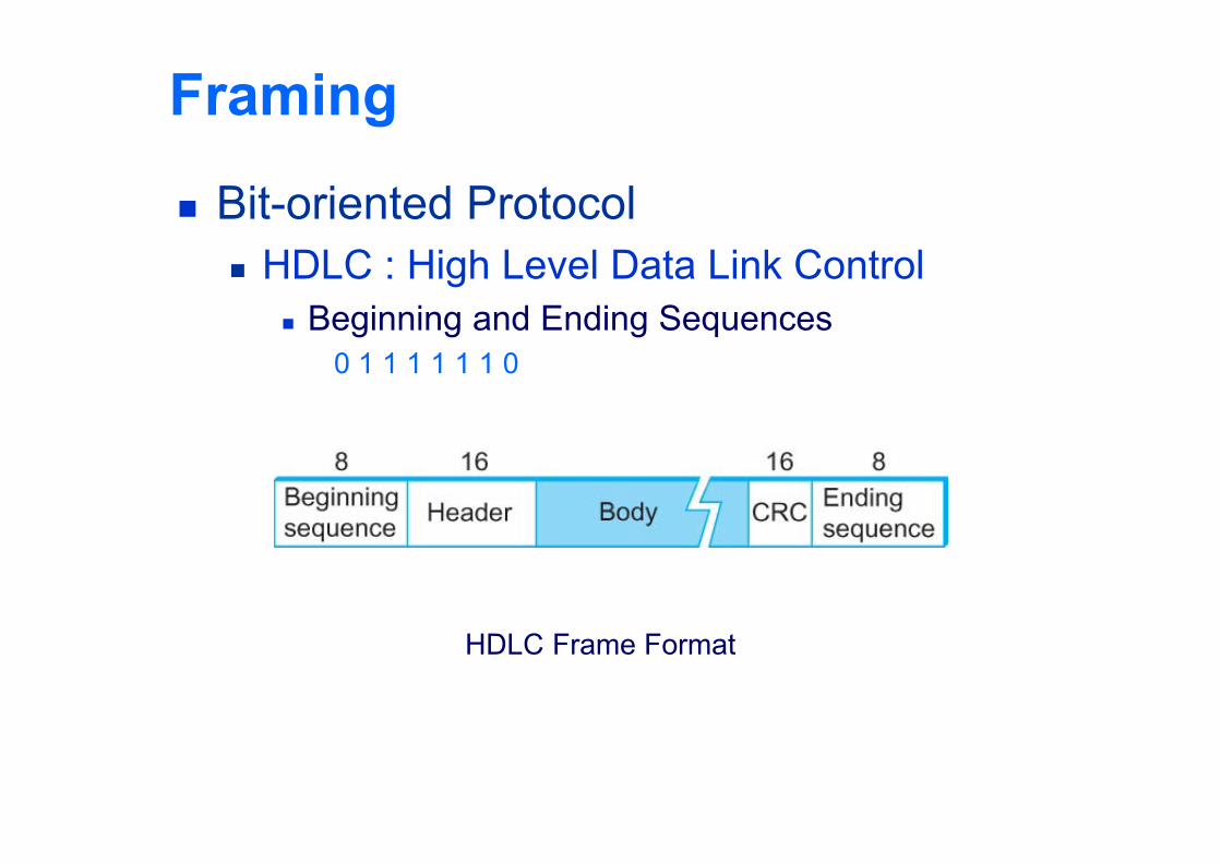
Bit-oriented Protocol HDLC : High Level Data Link Control
Beginning and Ending Sequences0 1 1 1 1 1 1 0
HDLC Frame Format
Framing
HDLC Protocol On the sending side, any time five consecutive
1’s have been transmitted from the body of the message (i.e. excluding when the sender is trying to send the distinguished 01111110 sequence) The sender inserts 0 before transmitting the next
bit
Framing HDLC Protocol
On the receiving side 5 consecutive 1’s
Next bit 0 : Stuffed, so discard it1 : Either End of the frame marker
Or Error has been introduced in the bitstreamLook at the next bitIf 0 ( 01111110 ) End of the frame markerIf 1 ( 01111111 ) Error, discard the whole frame
The receiver needs to wait for next 01111110 before it can start receiving again
Error Detection Bit errors are introduced into frames
Because of electrical interference and thermal noises Detecting Error Correction Error Two approaches when the recipient detects an
error Notify the sender that the message was corrupted, so
the sender can send again. If the error is rare, then the retransmitted message will be
error-free Using some error correct detection and correction
algorithm, the receiver reconstructs the message
Error Detection Common technique for detecting transmission
error CRC (Cyclic Redundancy Check)
Used in HDLC, DDCMP, CSMA/CD, Token Ring Other approaches
Two Dimensional Parity (BISYNC) Checksum (IP)
Error Detection Basic Idea of Error Detection
To add redundant information to a frame that can be used to determine if errors have been introduced
Imagine (Extreme Case) Transmitting two complete copies of data
Identical No error Differ Error Poor Scheme ???
n bit message, n bit redundant information Error can go undetected
In general, we can provide strong error detection technique k redundant bits, n bits message, k << n In Ethernet, a frame carrying up to 12,000 bits of data requires only 32-
bit CRC
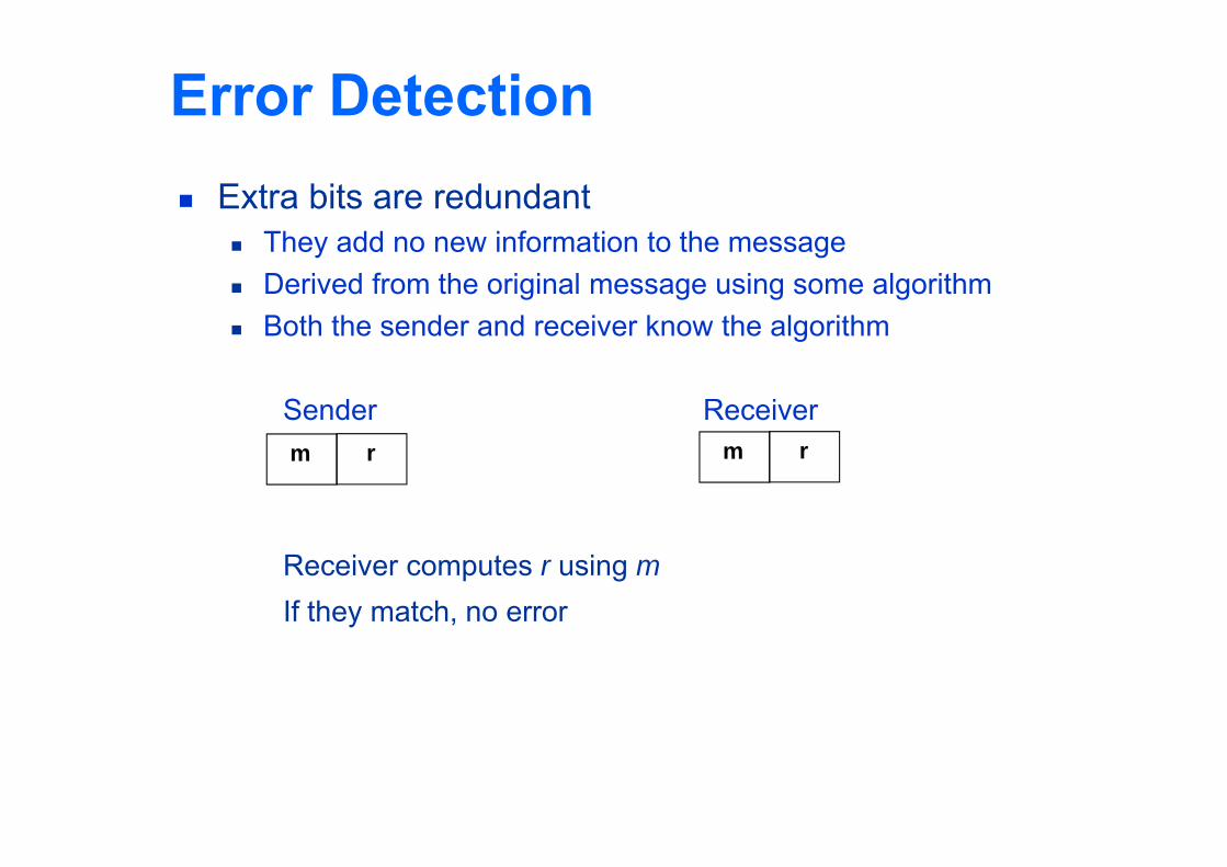
Error Detection Extra bits are redundant
They add no new information to the message Derived from the original message using some algorithm Both the sender and receiver know the algorithm
Sender Receiver
Receiver computes r using mIf they match, no error
m rm r
Two-dimensional parity Two-dimensional parity is exactly what the name
suggests It is based on “simple” (one-dimensional) parity,
which usually involves adding one extra bit to a 7-bit code to balance the number of 1s in the byte. For example, Odd parity sets the eighth bit to 1 if needed to give an
odd number of 1s in the byte, and Even parity sets the eighth bit to 1 if needed to give an
even number of 1s in the byte
Two-dimensional parity Two-dimensional parity does a similar
calculation for each bit position across each of the bytes contained in the frame
This results in an extra parity byte for the entire frame, in addition to a parity bit for each byte
Two-dimensional parity catches all 1-, 2-, and 3-bit errors and most 4-bit errors
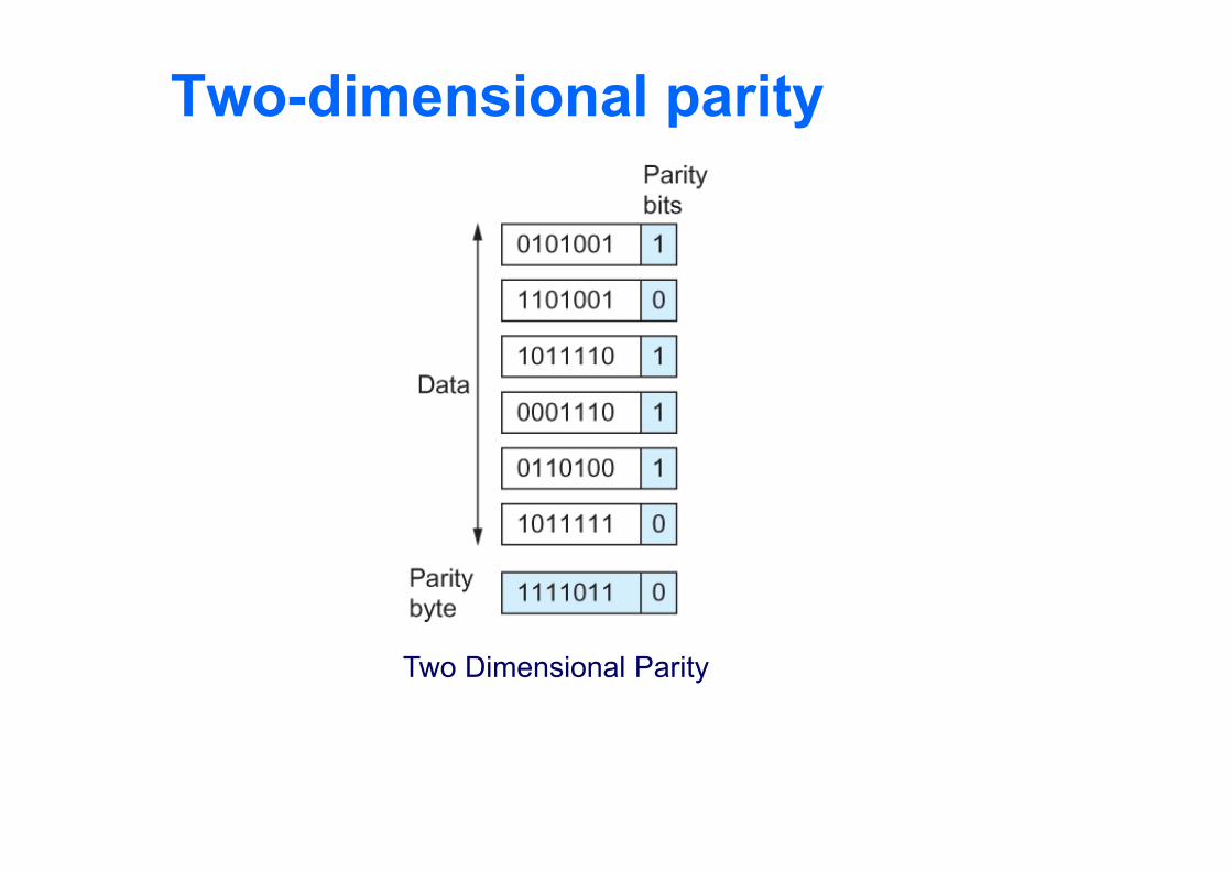
Two-dimensional parity
Two Dimensional Parity
Internet Checksum Algorithm Not used at the link level Add up all the words that are transmitted and
then transmit the result of that sum The result is called the checksum
The receiver performs the same calculation on the received data and compares the result with the received checksum
If any transmitted data, including the checksum itself, is corrupted, then the results will not match, so the receiver knows that an error occurred
Internet Checksum Algorithm Consider the data being checksummed as a
sequence of 16-bit integers. Add them together using 16-bit ones
complement arithmetic (explained next slide) and then take the ones complement of the result.
That 16-bit number is the checksum
Internet Checksum Algorithm In ones complement arithmetic, a negative
integer −x is represented as the complement of x; Each bit of x is inverted.
When adding numbers in ones complement arithmetic, a carryout from the most significant bit needs to be added to the result.
Internet Checksum Algorithm Consider, for example, the addition of −5 and −3
in ones complement arithmetic on 4-bit integers +5 is 0101, so −5 is 1010; +3 is 0011, so −3 is 1100
If we add 1010 and 1100 ignoring the carry, we get 0110
In ones complement arithmetic, the fact that this operation caused a carry from the most significant bit causes us to increment the result, giving 0111, which is the ones complement representation of −8 (obtained by inverting the bits in 1000), as we would expect
Cyclic Redundancy Check (CRC) Reduce the number of extra bits and maximize
protection Given a bit string 110001 we can associate a
polynomial on a single variable x for it.1.x5+1.x4+0.x3+0.x2+0.x1+1.x0 = x5+x4+1 and the degree
is 5.A k-bit frame has a maximum degree of k-1
Let M(x) be a message polynomial and C(x) be a generator polynomial.
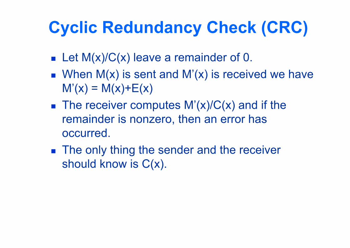
Cyclic Redundancy Check (CRC) Let M(x)/C(x) leave a remainder of 0. When M(x) is sent and M’(x) is received we have
M’(x) = M(x)+E(x) The receiver computes M’(x)/C(x) and if the
remainder is nonzero, then an error has occurred.
The only thing the sender and the receiver should know is C(x).
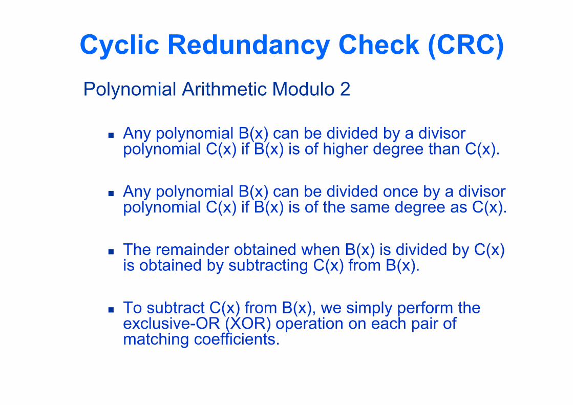
Cyclic Redundancy Check (CRC)Polynomial Arithmetic Modulo 2
Any polynomial B(x) can be divided by a divisor polynomial C(x) if B(x) is of higher degree than C(x).
Any polynomial B(x) can be divided once by a divisor polynomial C(x) if B(x) is of the same degree as C(x).
The remainder obtained when B(x) is divided by C(x) is obtained by subtracting C(x) from B(x).
To subtract C(x) from B(x), we simply perform the exclusive-OR (XOR) operation on each pair of matching coefficients.
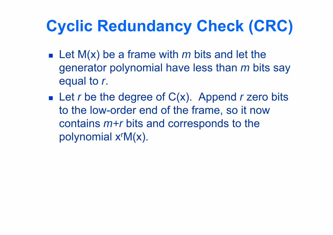
Cyclic Redundancy Check (CRC) Let M(x) be a frame with m bits and let the
generator polynomial have less than m bits say equal to r.
Let r be the degree of C(x). Append r zero bits to the low-order end of the frame, so it now contains m+r bits and corresponds to the polynomial xrM(x).
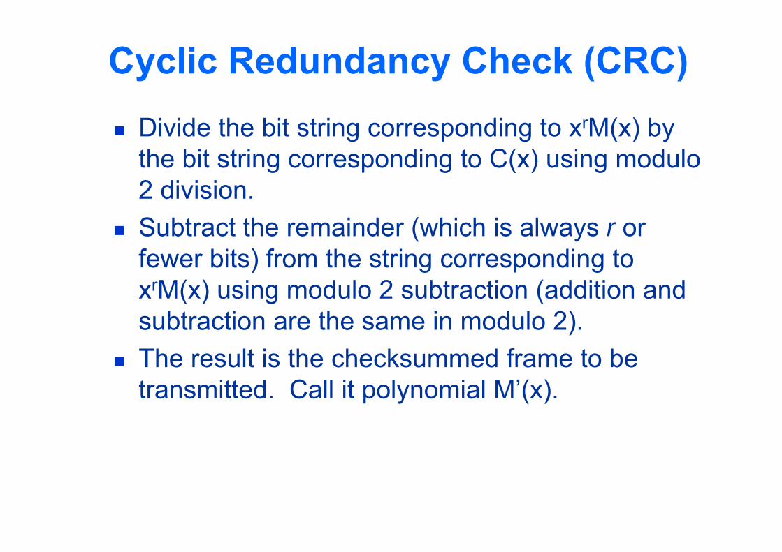
Cyclic Redundancy Check (CRC) Divide the bit string corresponding to xrM(x) by
the bit string corresponding to C(x) using modulo 2 division.
Subtract the remainder (which is always r or fewer bits) from the string corresponding to xrM(x) using modulo 2 subtraction (addition and subtraction are the same in modulo 2).
The result is the checksummed frame to be transmitted. Call it polynomial M’(x).
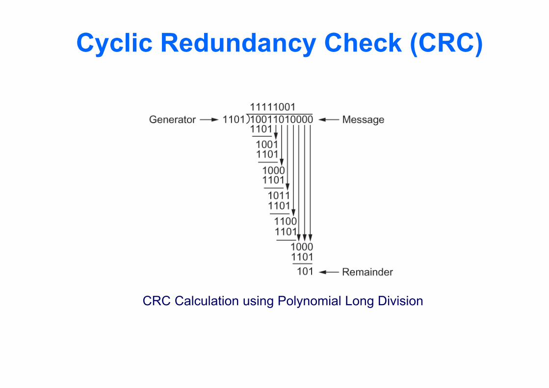
Cyclic Redundancy Check (CRC)
CRC Calculation using Polynomial Long Division
Cyclic Redundancy Check (CRC) Properties of Generator Polynomial
Let P(x) represent what the sender sent and P(x) + E(x) is the received string. A 1 in E(x) represents that in the corresponding position in P(x) the message the bit is flipped.
We know that P(x)/C(x) leaves a remainder of 0, but if E(x)/C(x) leaves a remainder of 0, then either E(x) = 0 or C(x) is factor of E(x).
When C(x) is a factor of E(x) we have problem; errors go unnoticed.
If there is a single bit error then E(x) = xi, where i determines the bit in error. If C(x) contains two or more terms it will never divide E(x), so all single bit errors will be detected.
Cyclic Redundancy Check (CRC) Properties of Generator Polynomial
In general, it is possible to prove that the following types of errors can be detected by a C(x) with the stated properties All single-bit errors, as long as the xk and x0 terms have
nonzero coefficients. All double-bit errors, as long as C(x) has a factor with at least
three terms. Any odd number of errors, as long as C(x) contains the factor
(x+1). Any “burst” error (i.e., sequence of consecutive error bits) for
which the length of the burst is less than k bits. (Most burst errors of larger than k bits can also be detected.)
Cyclic Redundancy Check (CRC) Six generator polynomials that have become
international standards are: CRC-8 = x8+x2+x+1 CRC-10 = x10+x9+x5+x4+x+1 CRC-12 = x12+x11+x3+x2+x+1 CRC-16 = x16+x15+x2+1 CRC-CCITT = x16+x12+x5+1 CRC-32 =
x32+x26+x23+x22+x16+x12+x11+x10+x8+x7+x5+x4+x2+x+1
Reliable Transmission CRC is used to detect errors. Some error codes are strong enough to correct
errors. The overhead is typically too high. Corrupt frames must be discarded. A link-level protocol that wants to deliver frames
reliably must recover from these discarded frames.
This is accomplished using a combination of two fundamental mechanisms Acknowledgements and Timeouts
Reliable Transmission An acknowledgement (ACK for short) is a small
control frame that a protocol sends back to its peer saying that it has received the earlier frame. A control frame is a frame with header only (no data).
The receipt of an acknowledgement indicates to the sender of the original frame that its frame was successfully delivered.
Reliable Transmission If the sender does not receive an
acknowledgment after a reasonable amount of time, then it retransmits the original frame.
The action of waiting a reasonable amount of time is called a timeout.
The general strategy of using acknowledgements and timeouts to implement reliable delivery is sometimes called AutomaticRepeat reQuest (ARQ).
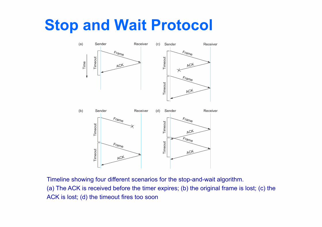
Stop and Wait Protocol Idea of stop-and-wait protocol is straightforward
After transmitting one frame, the sender waits for an acknowledgement before transmitting the next frame.
If the acknowledgement does not arrive after a certain period of time, the sender times out and retransmits the original frame
Stop and Wait Protocol
Timeline showing four different scenarios for the stop-and-wait algorithm.(a) The ACK is received before the timer expires; (b) the original frame is lost; (c) theACK is lost; (d) the timeout fires too soon
Stop and Wait Protocol If the acknowledgment is lost or delayed in arriving
The sender times out and retransmits the original frame, but the receiver will think that it is the next frame since it has correctly received and acknowledged the first frame
As a result, duplicate copies of frames will be delivered
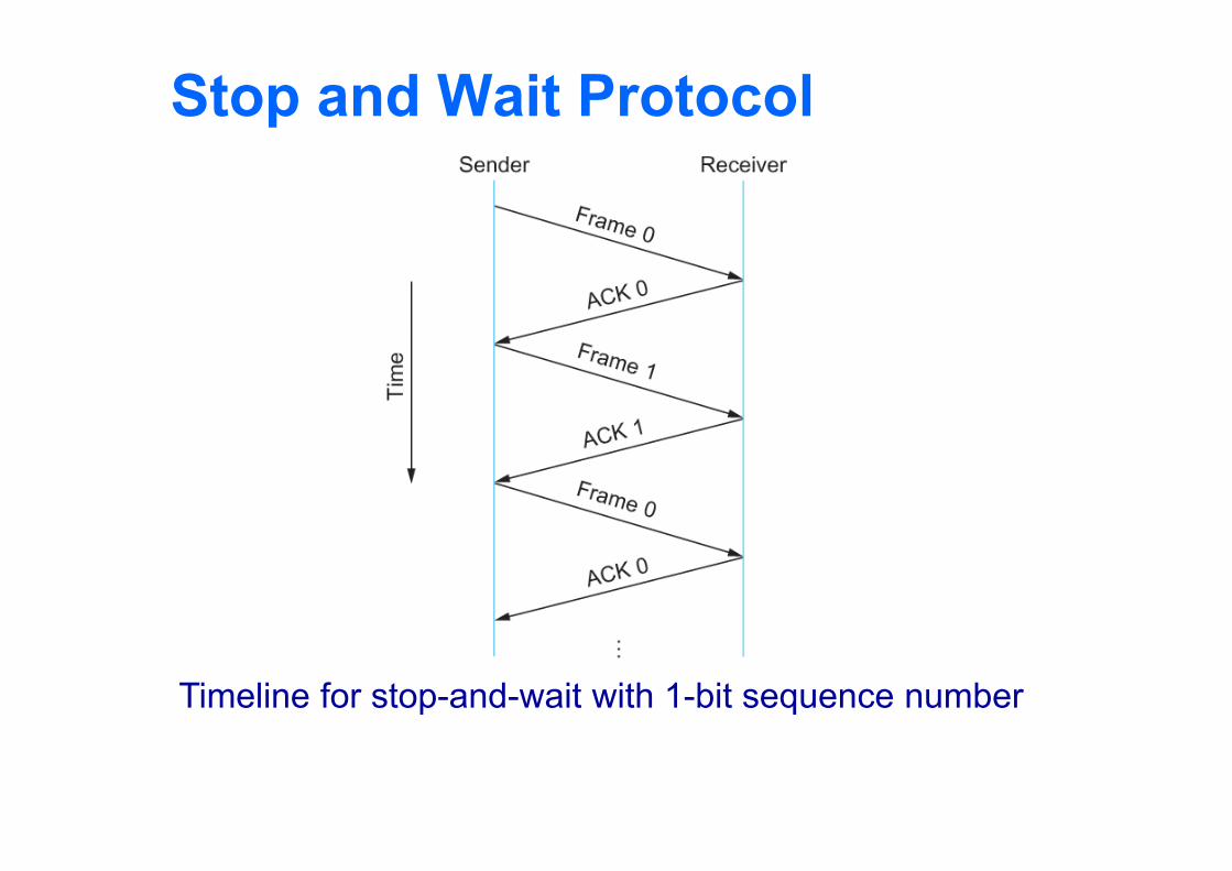
How to solve this Use 1 bit sequence number (0 or 1) When the sender retransmits frame 0, the receiver can determine
that it is seeing a second copy of frame 0 rather than the first copy of frame 1 and therefore can ignore it (the receiver still acknowledges it, in case the first acknowledgement was lost)
Stop and Wait Protocol
Timeline for stop-and-wait with 1-bit sequence number
Stop and Wait Protocol The sender has only one outstanding frame on the link at
a time This may be far below the link’s capacity
Consider a 1.5 Mbps link with a 45 ms RTT The link has a delay bandwidth product of 67.5 Kb or
approximately 8 KB Since the sender can send only one frame per RTT and
assuming a frame size of 1 KB Maximum Sending rate
Bits per frame Time per frame = 1024 8 0.045 = 182 KbpsOr about one-eighth of the link’s capacity
To use the link fully, then sender should transmit up to eight frames before having to wait for an acknowledgement
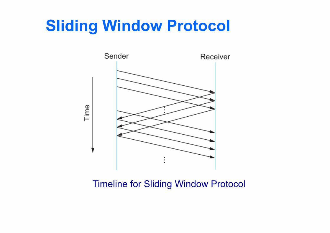
Sliding Window Protocol
Timeline for Sliding Window Protocol
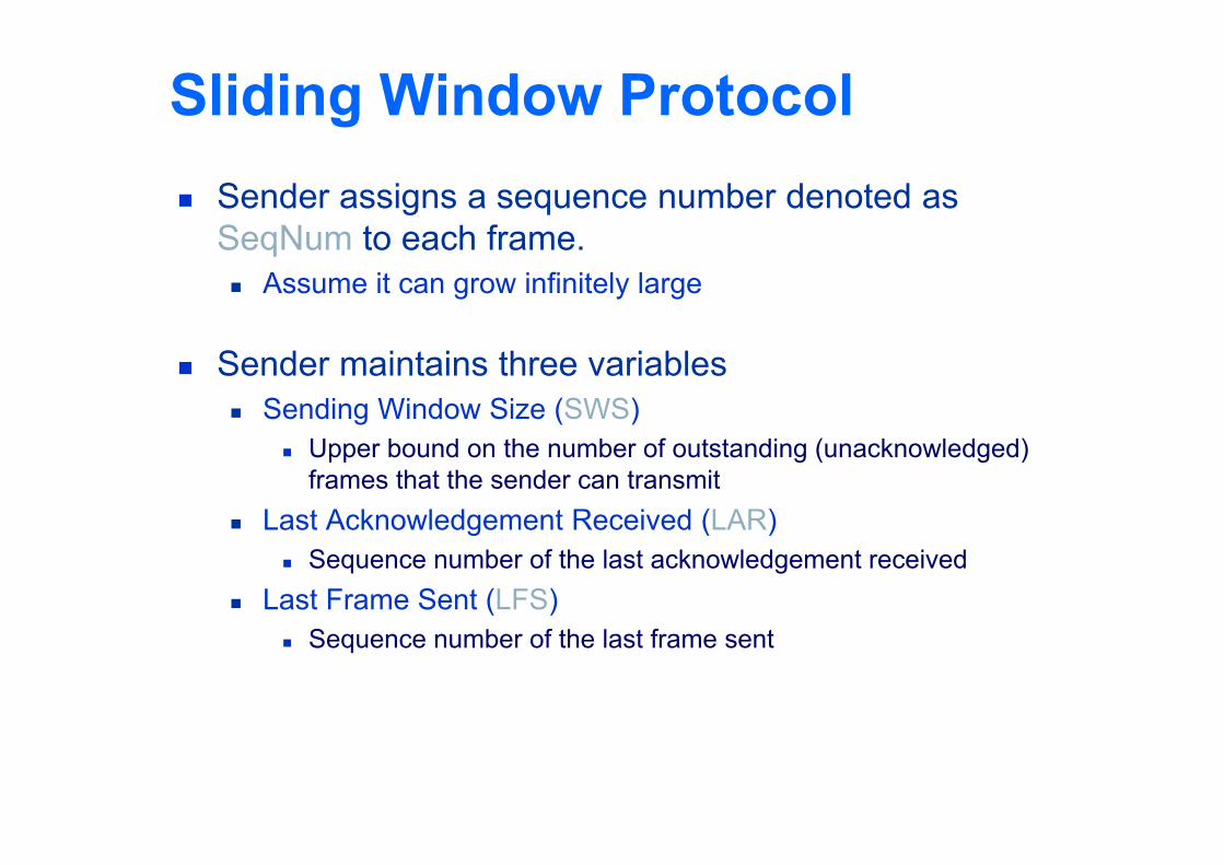
Sliding Window Protocol Sender assigns a sequence number denoted as
SeqNum to each frame. Assume it can grow infinitely large
Sender maintains three variables Sending Window Size (SWS)
Upper bound on the number of outstanding (unacknowledged) frames that the sender can transmit
Last Acknowledgement Received (LAR) Sequence number of the last acknowledgement received
Last Frame Sent (LFS) Sequence number of the last frame sent
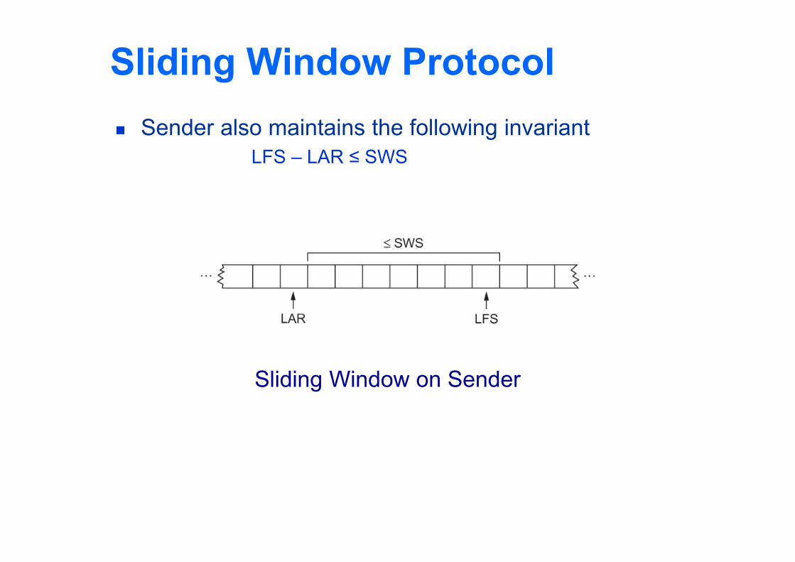
Sliding Window Protocol Sender also maintains the following invariant
LFS – LAR ≤ SWS
Sliding Window on Sender
Sliding Window Protocol When an acknowledgement arrives
the sender moves LAR to right, thereby allowing the sender to transmit another frame
Also the sender associates a timer with each frame it transmits It retransmits the frame if the timer expires before the ACK is
received Note that the sender has to be willing to buffer up to
SWS frames WHY?
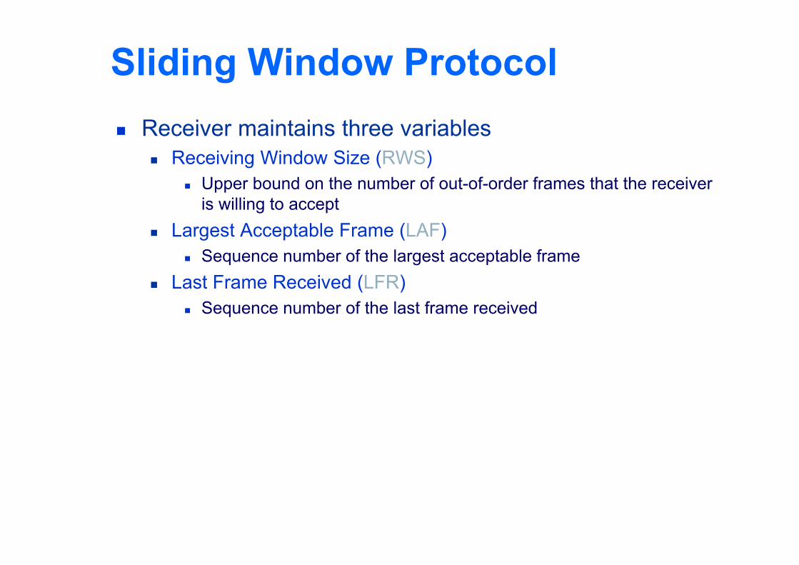
Sliding Window Protocol Receiver maintains three variables
Receiving Window Size (RWS) Upper bound on the number of out-of-order frames that the receiver
is willing to accept Largest Acceptable Frame (LAF)
Sequence number of the largest acceptable frame Last Frame Received (LFR)
Sequence number of the last frame received
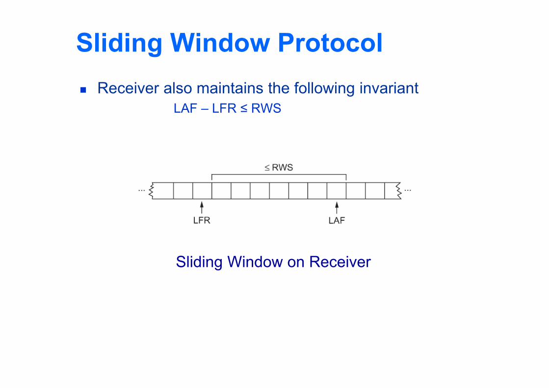
Sliding Window Protocol Receiver also maintains the following invariant
LAF – LFR ≤ RWS
Sliding Window on Receiver
Sliding Window Protocol When a frame with sequence number SeqNum arrives,
what does the receiver do?
If SeqNum ≤ LFR or SeqNum > LAF Discard it (the frame is outside the receiver window)
If LFR < SeqNum ≤ LAF Accept it Now the receiver needs to decide whether or not to send an ACK
Sliding Window Protocol Let SeqNumToAck
Denote the largest sequence number not yet acknowledged, such that all frames with sequence number less than or equal to SeqNumToAck have been received
The receiver acknowledges the receipt of SeqNumToAck even if high-numbered packets have been received This acknowledgement is said to be cumulative.
The receiver then sets LFR = SeqNumToAck and adjusts LAF = LFR + RWS
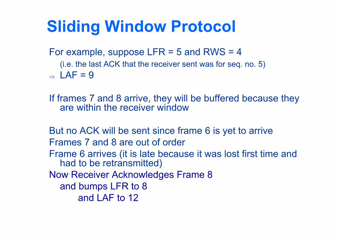
Sliding Window ProtocolFor example, suppose LFR = 5 and RWS = 4
(i.e. the last ACK that the receiver sent was for seq. no. 5) LAF = 9
If frames 7 and 8 arrive, they will be buffered because they are within the receiver window
But no ACK will be sent since frame 6 is yet to arriveFrames 7 and 8 are out of orderFrame 6 arrives (it is late because it was lost first time and
had to be retransmitted)Now Receiver Acknowledges Frame 8
and bumps LFR to 8and LAF to 12
Issues with Sliding Window Protocol
When timeout occurs, the amount of data in transit decreases Since the sender is unable to advance its window
When the packet loss occurs, this scheme is no longer keeping the pipe full The longer it takes to notice that a packet loss has occurred, the
more severe the problem becomes
How to improve this Negative Acknowledgement (NAK) Additional Acknowledgement Selective Acknowledgement
Issues with Sliding Window Protocol Negative Acknowledgement (NAK)
Receiver sends NAK for frame 6 when frame 7 arrive (in the previous example) However this is unnecessary since sender’s timeout mechanism will be
sufficient to catch the situation
Additional Acknowledgement Receiver sends additional ACK for frame 5 when frame 7 arrives
Sender uses duplicate ACK as a clue for frame loss
Selective Acknowledgement Receiver will acknowledge exactly those frames it has received, rather
than the highest number frames Receiver will acknowledge frames 7 and 8 Sender knows frame 6 is lost Sender can keep the pipe full (additional complexity)
Issues with Sliding Window Protocol
How to select the window size SWS is easy to compute
Delay Bandwidth RWS can be anything
Two common setting RWS = 1
No buffer at the receiver for frames that arrive out of order
RWS = SWSThe receiver can buffer frames that the sender transmits
It does not make any sense to keep RWS > SWSWHY?
Issues with Sliding Window Protocol
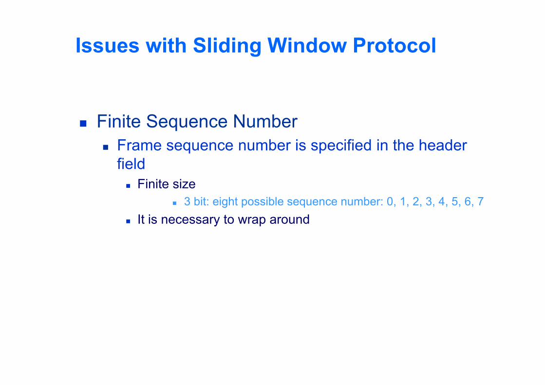
Finite Sequence Number Frame sequence number is specified in the header
field Finite size
3 bit: eight possible sequence number: 0, 1, 2, 3, 4, 5, 6, 7 It is necessary to wrap around
Issues with Sliding Window Protocol
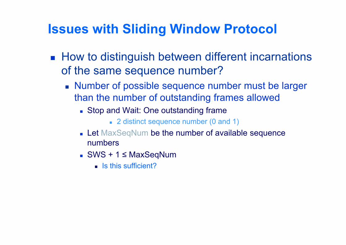
How to distinguish between different incarnations of the same sequence number? Number of possible sequence number must be larger
than the number of outstanding frames allowed Stop and Wait: One outstanding frame
2 distinct sequence number (0 and 1) Let MaxSeqNum be the number of available sequence
numbers SWS + 1 ≤ MaxSeqNum
Is this sufficient?
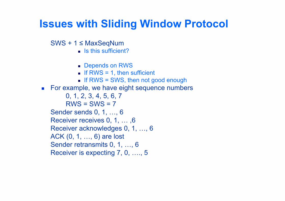
Issues with Sliding Window ProtocolSWS + 1 ≤ MaxSeqNum
Is this sufficient?
Depends on RWS If RWS = 1, then sufficient If RWS = SWS, then not good enough
For example, we have eight sequence numbers0, 1, 2, 3, 4, 5, 6, 7RWS = SWS = 7
Sender sends 0, 1, …, 6Receiver receives 0, 1, … ,6Receiver acknowledges 0, 1, …, 6ACK (0, 1, …, 6) are lostSender retransmits 0, 1, …, 6Receiver is expecting 7, 0, …., 5
Issues with Sliding Window Protocol
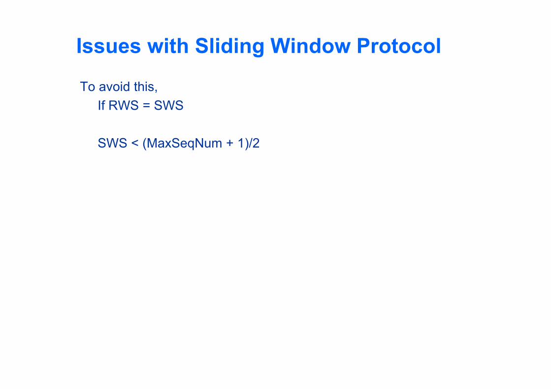
To avoid this, If RWS = SWS
SWS < (MaxSeqNum + 1)/2
Issues with Sliding Window Protocol
Serves three different roles Reliable Preserve the order
Each frame has a sequence number The receiver makes sure that it does not pass a frame up to
the next higher-level protocol until it has already passed up all frames with a smaller sequence number
Frame control Receiver is able to throttle the sender
Keeps the sender from overrunning the receiver From transmitting more data than the receiver is able to
process
Ethernet Most successful local area networking technology of last
20 years. Developed in the mid-1970s by researchers at the Xerox
Palo Alto Research Centers (PARC). Uses CSMA/CD technology
Carrier Sense Multiple Access with Collision Detection. A set of nodes send and receive frames over a shared link. Carrier sense means that all nodes can distinguish between an
idle and a busy link. Collision detection means that a node listens as it transmits and
can therefore detect when a frame it is transmitting has collided with a frame transmitted by another node.
Ethernet Uses ALOHA (packet radio network) as the root protocol
Developed at the University of Hawaii to support communication across the Hawaiian Islands.
For ALOHA the medium was atmosphere, for Ethernet the medium is a coax cable.
DEC and Intel joined Xerox to define a 10-Mbps Ethernet standard in 1978.
This standard formed the basis for IEEE standard 802.3 More recently 802.3 has been extended to include a 100-
Mbps version called Fast Ethernet and a 1000-Mbps version called Gigabit Ethernet.
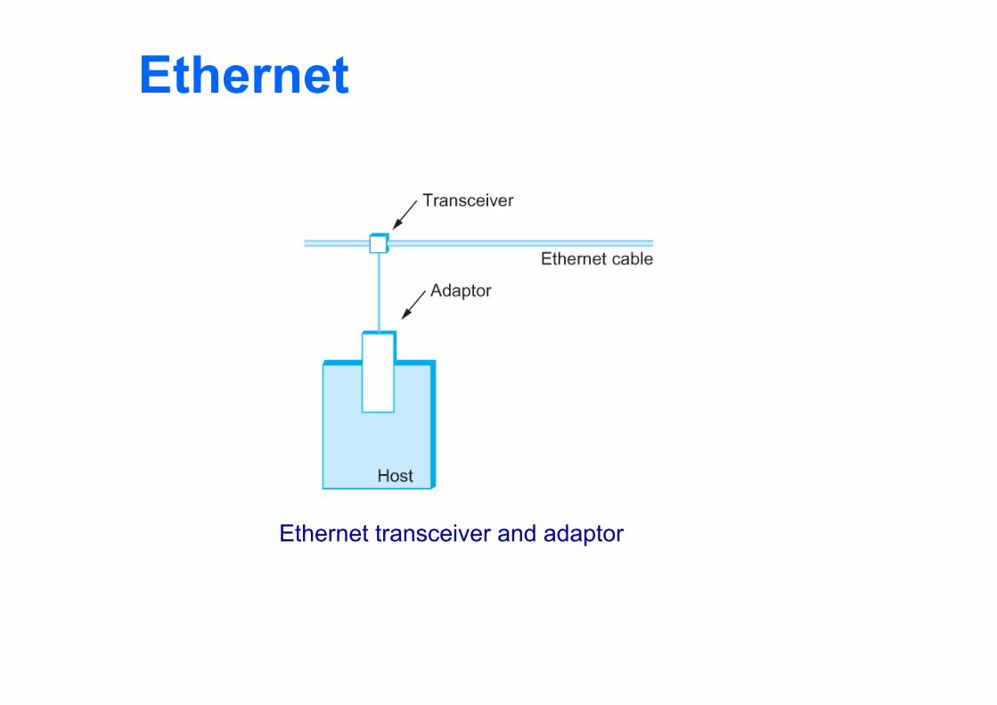
Ethernet An Ethernet segment is implemented on a coaxial cable of up
to 500 m. This cable is similar to the type used for cable TV except that it
typically has an impedance of 50 ohms instead of cable TV’s 75 ohms.
Hosts connect to an Ethernet segment by tapping into it. A transceiver (a small device directly attached to the tap)
detects when the line is idle and drives signal when the host is transmitting.
The transceiver also receives incoming signal. The transceiver is connected to an Ethernet adaptor which is
plugged into the host. The protocol is implemented on the adaptor.
Ethernet
Ethernet transceiver and adaptor
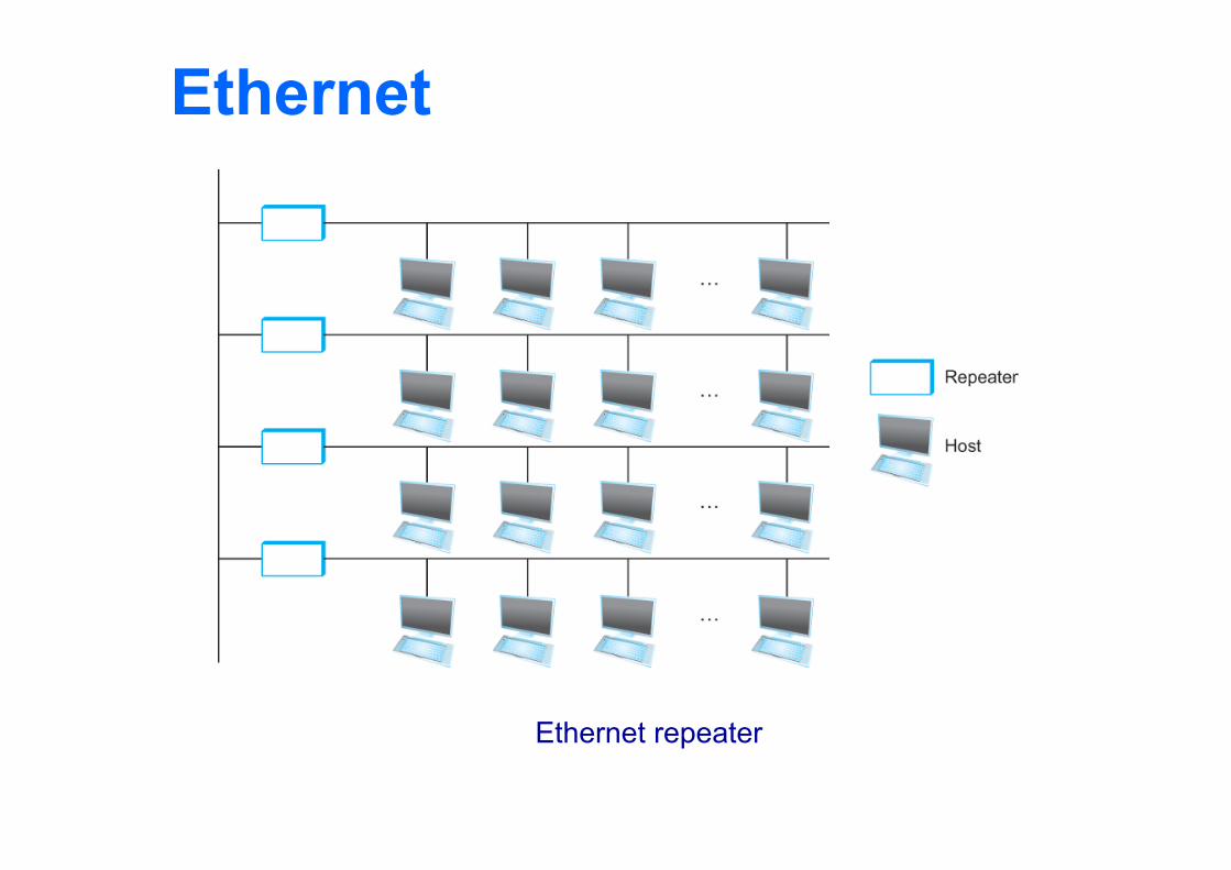
Ethernet Multiple Ethernet segments can be joined together by
repeaters. A repeater is a device that forwards digital signals. No more than four repeaters may be positioned between
any pair of hosts. An Ethernet has a total reach of only 2500 m.
Ethernet
Ethernet repeater
Ethernet Any signal placed on the Ethernet by a host is
broadcast over the entire network Signal is propagated in both directions. Repeaters forward the signal on all outgoing
segments. Terminators attached to the end of each segment
absorb the signal.
Ethernet uses Manchester encoding scheme.
Ethernet New Technologies in Ethernet
Instead of using coax cable, an Ethernet can be constructed from a thinner cable known as 10Base2 (the original was 10Base5) 10 means the network operates at 10 Mbps Base means the cable is used in a baseband system 2 means that a given segment can be no longer than 200 m
Ethernet New Technologies in Ethernet
Another cable technology is 10BaseT T stands for twisted pair Limited to 100 m in length
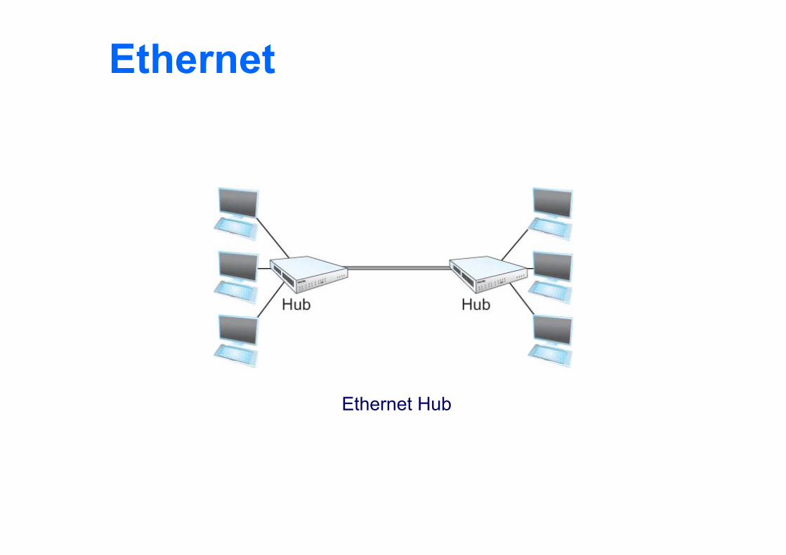
With 10BaseT, the common configuration is to have several point to point segments coming out of a multiway repeater, called Hub
Ethernet
Ethernet Hub
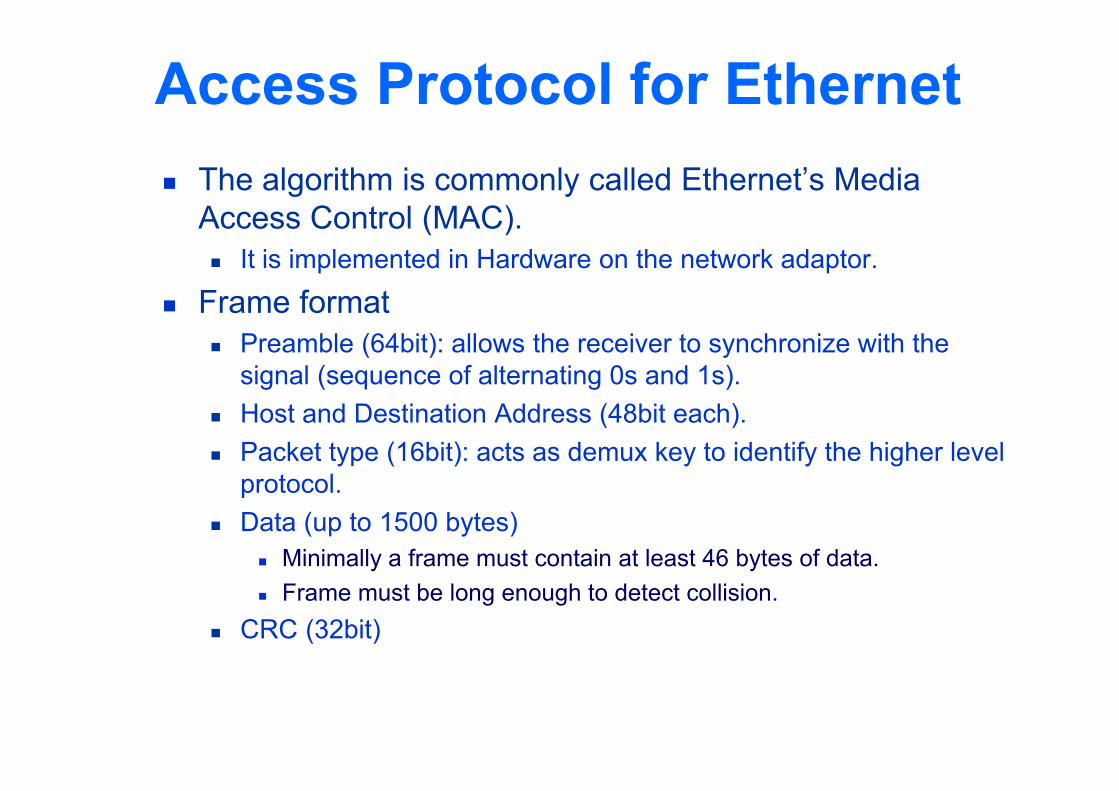
Access Protocol for Ethernet The algorithm is commonly called Ethernet’s Media
Access Control (MAC). It is implemented in Hardware on the network adaptor.
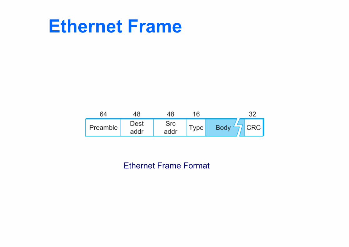
Frame format Preamble (64bit): allows the receiver to synchronize with the
signal (sequence of alternating 0s and 1s). Host and Destination Address (48bit each). Packet type (16bit): acts as demux key to identify the higher level
protocol. Data (up to 1500 bytes)
Minimally a frame must contain at least 46 bytes of data. Frame must be long enough to detect collision.
CRC (32bit)
Ethernet Frame
Ethernet Frame Format
Copyright © 2010, Elsevier Inc.
Ethernet Addresses Each host on an Ethernet (in fact, every Ethernet host in
the world) has a unique Ethernet Address. The address belongs to the adaptor, not the host.
It is usually burnt into ROM. Ethernet addresses are typically printed in a human
readable format As a sequence of six numbers separated by colons. Each number corresponds to 1 byte of the 6 byte address and is
given by a pair of hexadecimal digits, one for each of the 4-bit nibbles in the byte
Leading 0s are dropped. For example, 8:0:2b:e4:b1:2 is
00001000 00000000 00101011 11100100 10110001 00000010
Ethernet Addresses To ensure that every adaptor gets a unique address,
each manufacturer of Ethernet devices is allocated a different prefix that must be prepended to the address on every adaptor they build
AMD has been assigned the 24bit prefix 8:0:20
Ethernet Addresses Each frame transmitted on an Ethernet is received by
every adaptor connected to that Ethernet. Each adaptor recognizes those frames addressed to its
address and passes only those frames on to the host. In addition, to unicast address, an Ethernet address
consisting of all 1s is treated as a broadcast address. All adaptors pass frames addressed to the broadcast address up
to the host. Similarly, an address that has the first bit set to 1 but is
not the broadcast address is called a multicast address. A given host can program its adaptor to accept some set of
multicast addresses.
Ethernet Addresses To summarize, an Ethernet adaptor receives all frames
and accepts Frames addressed to its own address Frames addressed to the broadcast address Frames addressed to a multicast addressed if it has been
instructed
Ethernet Transmitter Algorithm When the adaptor has a frame to send and the line is
idle, it transmits the frame immediately. The upper bound of 1500 bytes in the message means that the
adaptor can occupy the line for a fixed length of time. When the adaptor has a frame to send and the line is
busy, it waits for the line to go idle and then transmits immediately.
The Ethernet is said to be 1-persistent protocol because an adaptor with a frame to send transmits with probability 1 whenever a busy line goes idle.
Ethernet Transmitter Algorithm Since there is no centralized control it is possible for two
(or more) adaptors to begin transmitting at the same time, Either because both found the line to be idle, Or, both had been waiting for a busy line to become idle.
When this happens, the two (or more) frames are said to be collide on the network.
Ethernet Transmitter Algorithm Since Ethernet supports collision detection, each sender
is able to determine that a collision is in progress. At the moment an adaptor detects that its frame is
colliding with another, it first makes sure to transmit a 32-bit jamming sequence and then stops transmission. Thus, a transmitter will minimally send 96 bits in the case of
collision 64-bit preamble + 32-bit jamming sequence
Ethernet Transmitter Algorithm One way that an adaptor will send only 96 bit (called a
runt frame) is if the two hosts are close to each other. Had they been farther apart,
They would have had to transmit longer, and thus send more bits, before detecting the collision.
Ethernet Transmitter Algorithm The worst case scenario happens when the two hosts
are at opposite ends of the Ethernet. To know for sure that the frame its just sent did not
collide with another frame, the transmitter may need to send as many as 512 bits. Every Ethernet frame must be at least 512 bits (64 bytes) long.
14 bytes of header + 46 bytes of data + 4 bytes of CRC
Ethernet Transmitter Algorithm Why 512 bits?
Why is its length limited to 2500 m?
The farther apart two nodes are, the longer it takes for a frame sent by one to reach the other, and the network is vulnerable to collision during this time
Ethernet Transmitter Algorithm A begins transmitting a frame at time t d denotes the one link latency The first bit of A’s frame arrives at B at time t + d Suppose an instant before host A’s frame arrives, host B
begins to transmit its own frame B’s frame will immediately collide with A’s frame and this
collision will be detected by host B Host B will send the 32-bit jamming sequence Host A will not know that the collision occurred until B’s
frame reaches it, which will happen at t + 2 * d Host A must continue to transmit until this time in order to
detect the collision Host A must transmit for 2 * d to be sure that it detects all
possible collisions
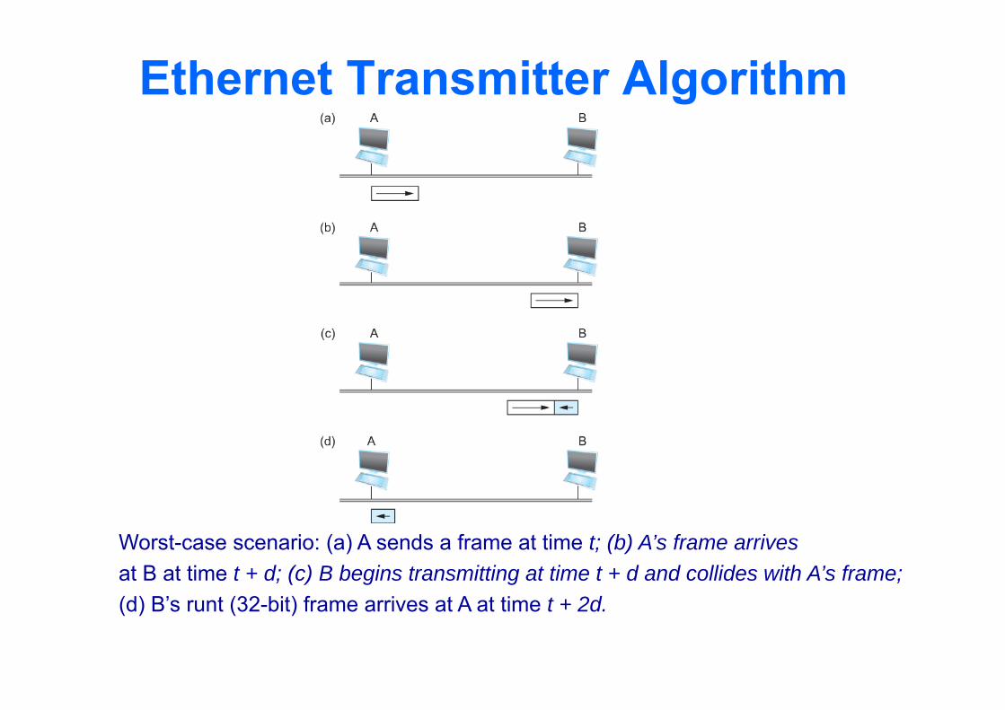
Ethernet Transmitter Algorithm
Worst-case scenario: (a) A sends a frame at time t; (b) A’s frame arrivesat B at time t + d; (c) B begins transmitting at time t + d and collides with A’s frame;(d) B’s runt (32-bit) frame arrives at A at time t + 2d.
Copyright © 2010, Elsevier Inc.
Ethernet Transmitter Algorithm Consider that a maximally configured Ethernet is
2500 m long, and there may be up to four repeaters between any two hosts, the round trip delay has been determined to be 51.2 s Which on 10 Mbps Ethernet corresponds to 512 bits
The other way to look at this situation, We need to limit the Ethernet’s maximum latency to a
fairly small value (51.2 s) for the access algorithm to work Hence the maximum length for the Ethernet is on the order of
2500 m.
Ethernet Transmitter Algorithm Once an adaptor has detected a collision, and stopped
its transmission, it waits a certain amount of time and tries again.
Each time the adaptor tries to transmit but fails, it doubles the amount of time it waits before trying again.
This strategy of doubling the delay interval between each retransmission attempt is known as Exponential Backoff.
Ethernet Transmitter Algorithm The adaptor first delays either 0 or 51.2 s, selected at
random. If this effort fails, it then waits 0, 51.2, 102.4, 153.6 s
(selected randomly) before trying again; This is k * 51.2 for k = 0, 1, 2, 3
After the third collision, it waits k * 51.2 for k = 0…23 – 1 (again selected at random).
In general, the algorithm randomly selects a k between 0 and 2n – 1 and waits for k * 51.2 s, where n is the number of collisions experienced so far.
Copyright © 2010, Elsevier Inc.
Experience with Ethernet Ethernets work best under lightly loaded conditions.
Under heavy loads, too much of the network’s capacity is wasted by collisions.
Most Ethernets are used in a conservative way. Have fewer than 200 hosts connected to them which is far fewer
than the maximum of 1024. Most Ethernets are far shorter than 2500m with a round-
trip delay of closer to 5 s than 51.2 s. Ethernets are easy to administer and maintain.
There are no switches that can fail and no routing and configuration tables that have to be kept up-to-date.
It is easy to add a new host to the network. It is inexpensive.
Cable is cheap, and only other cost is the network adaptor on each host.
Wireless Links Wireless links transmit electromagnetic signals
Radio, microwave, infrared Wireless links all share the same “wire” (so to speak)
The challenge is to share it efficiently without unduly interfering with each other
Most of this sharing is accomplished by dividing the “wire” along the dimensions of frequency and space
Exclusive use of a particular frequency in a particular geographic area may be allocated to an individual entity such as a corporation
Wireless Links These allocations are determined by government
agencies such as FCC (Federal Communications Commission) in USA
Specific bands (frequency) ranges are allocated to certain uses. Some bands are reserved for government use Other bands are reserved for uses such as AM radio, FM radio,
televisions, satellite communications, and cell phones Specific frequencies within these bands are then allocated to
individual organizations for use within certain geographical areas. Finally, there are several frequency bands set aside for “license
exempt” usage Bands in which a license is not needed
Wireless Links Devices that use license-exempt frequencies are still
subject to certain restrictions The first is a limit on transmission power This limits the range of signal, making it less likely to interfere
with another signal For example, a cordless phone might have a range of about 100 feet.
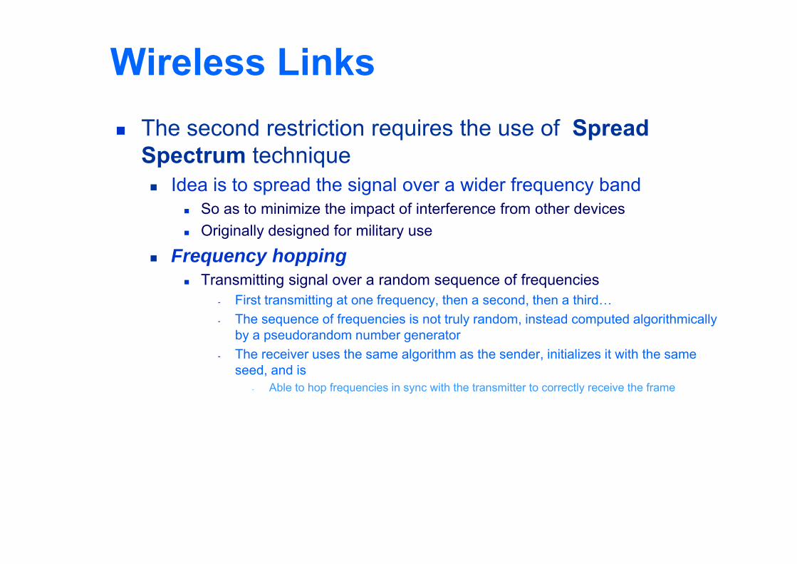
Wireless Links The second restriction requires the use of Spread
Spectrum technique Idea is to spread the signal over a wider frequency band
So as to minimize the impact of interference from other devices Originally designed for military use
Frequency hopping Transmitting signal over a random sequence of frequencies
- First transmitting at one frequency, then a second, then a third…- The sequence of frequencies is not truly random, instead computed algorithmically
by a pseudorandom number generator- The receiver uses the same algorithm as the sender, initializes it with the same
seed, and is- Able to hop frequencies in sync with the transmitter to correctly receive the frame
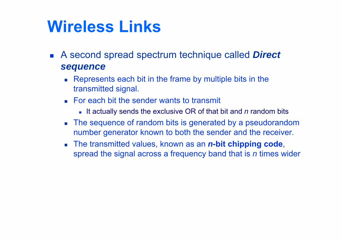
Wireless Links A second spread spectrum technique called Direct
sequence Represents each bit in the frame by multiple bits in the
transmitted signal. For each bit the sender wants to transmit
It actually sends the exclusive OR of that bit and n random bits The sequence of random bits is generated by a pseudorandom
number generator known to both the sender and the receiver. The transmitted values, known as an n-bit chipping code,
spread the signal across a frequency band that is n times wider
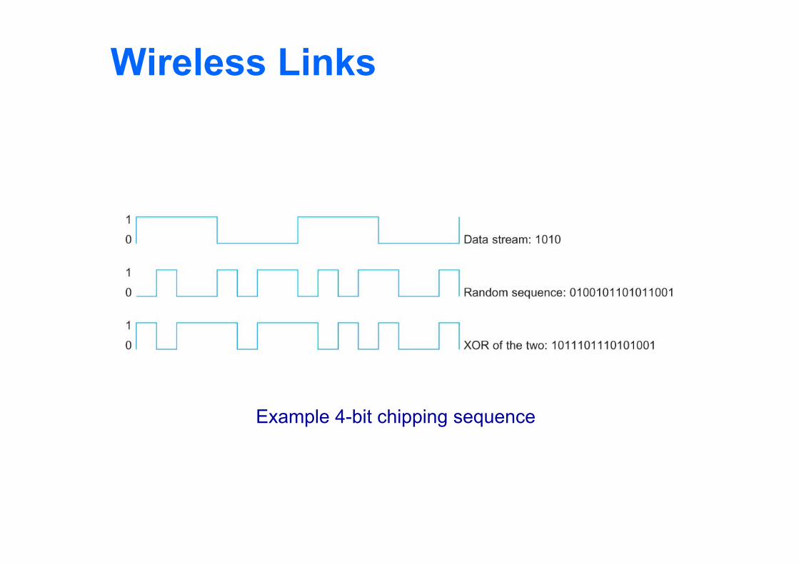
Wireless Links
Example 4-bit chipping sequence
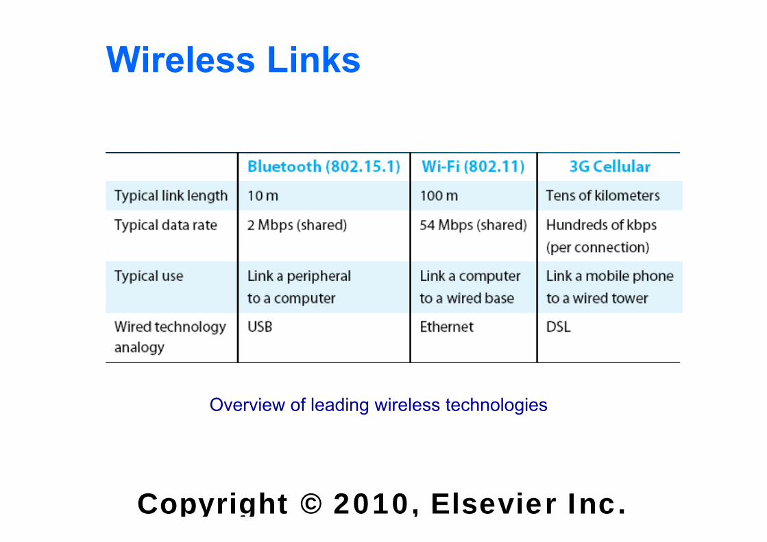
Wireless Links Wireless technologies differ in a variety of dimensions
How much bandwidth they provide How far apart the communication nodes can be
Four prominent wireless technologies Bluetooth Wi-Fi (more formally known as 802.11) WiMAX (802.16) 3G cellular wireless
Copyright © 2010, Elsevier Inc.
Wireless Links
Overview of leading wireless technologies
Wireless Links Mostly widely used wireless links today are usually
asymmetric Two end-points are usually different kinds of nodes
One end-point usually has no mobility, but has wired connection to the Internet (known as base station)
The node at the other end of the link is often mobile
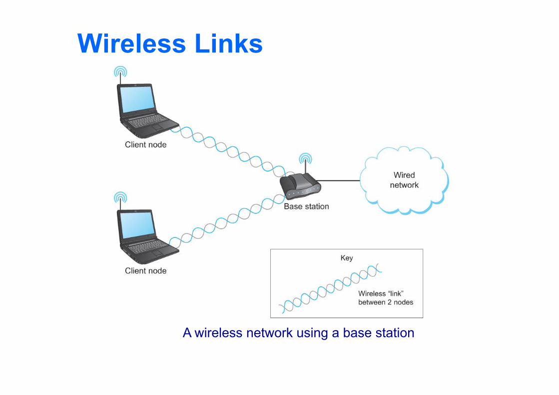
Wireless Links
A wireless network using a base station
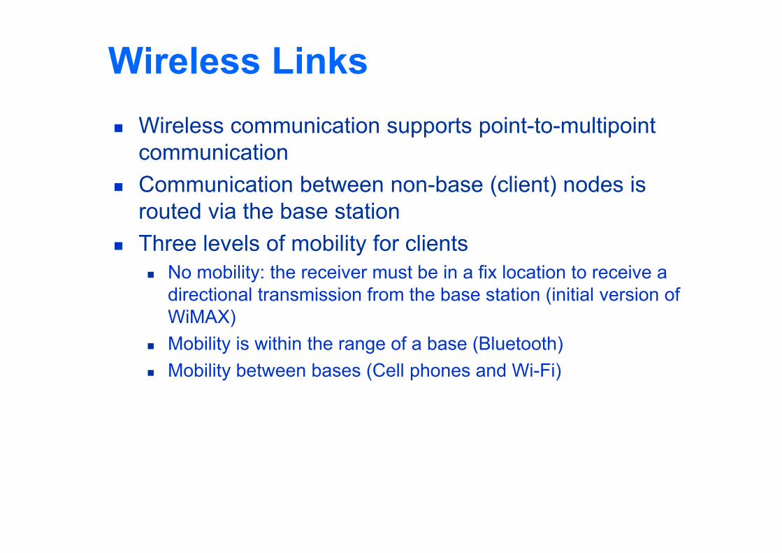
Wireless Links Wireless communication supports point-to-multipoint
communication Communication between non-base (client) nodes is
routed via the base station Three levels of mobility for clients
No mobility: the receiver must be in a fix location to receive a directional transmission from the base station (initial version of WiMAX)
Mobility is within the range of a base (Bluetooth) Mobility between bases (Cell phones and Wi-Fi)
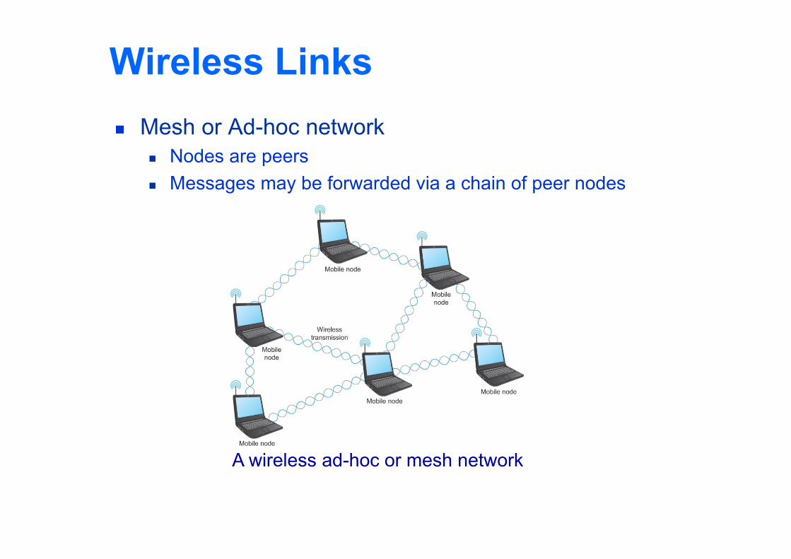
Wireless Links Mesh or Ad-hoc network
Nodes are peers Messages may be forwarded via a chain of peer nodes
A wireless ad-hoc or mesh network
IEEE 802.11 Also known as Wi-Fi Like its Ethernet and token ring siblings, 802.11 is
designed for use in a limited geographical area (homes, office buildings, campuses) Primary challenge is to mediate access to a shared
communication medium – in this case, signals propagating through space
802.11 supports additional features power management and security mechanisms
Copyright © 2010, Elsevier Inc.
IEEE 802.11 Original 802.11 standard defined two radio-based physical layer
standard One using the frequency hopping
Over 79 1-MHz-wide frequency bandwidths Second using direct sequence
Using 11-bit chipping sequence Both standards run in the 2.4-GHz and provide up to 2 Mbps
Then physical layer standard 802.11b was added Using a variant of direct sequence 802.11b provides up to 11 Mbps Uses license-exempt 2.4-GHz band
Then came 802.11a which delivers up to 54 Mbps using OFDM 802.11a runs on license-exempt 5-GHz band
Most recent standard is 802.11g which is backward compatible with 802.11b Uses 2.4 GHz band, OFDM and delivers up to 54 Mbps
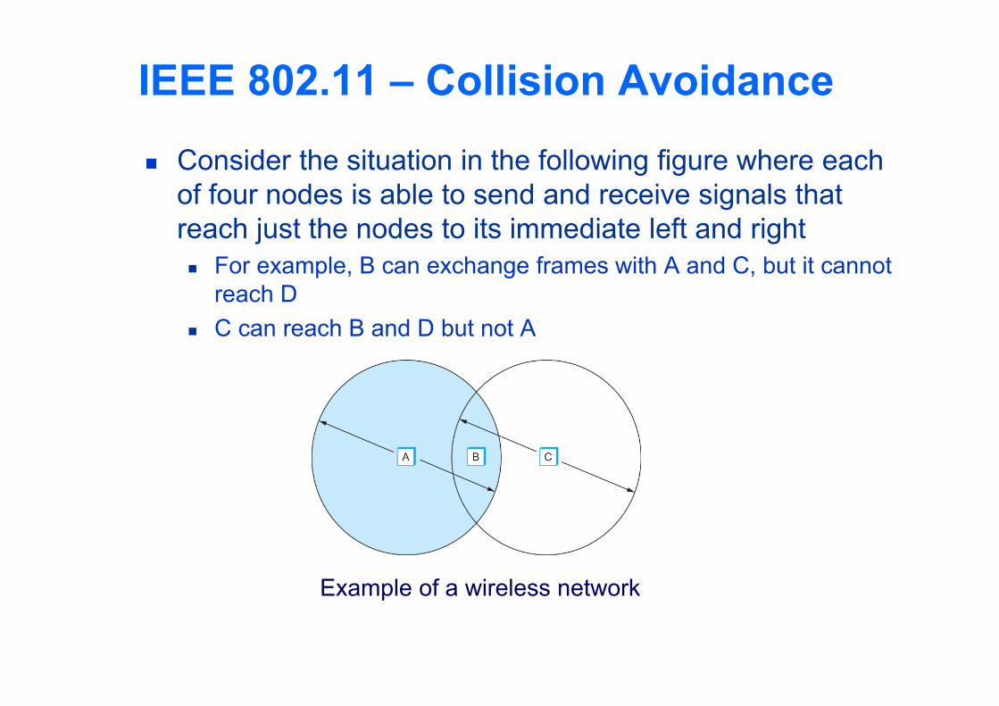
IEEE 802.11 – Collision Avoidance Consider the situation in the following figure where each
of four nodes is able to send and receive signals that reach just the nodes to its immediate left and right For example, B can exchange frames with A and C, but it cannot
reach D C can reach B and D but not A
Example of a wireless network
IEEE 802.11 – Collision Avoidance Suppose both A and C want to communicate with B and
so they each send it a frame. A and C are unaware of each other since their signals do not
carry that far These two frames collide with each other at B
But unlike an Ethernet, neither A nor C is aware of this collision A and C are said to hidden nodes with respect to each other
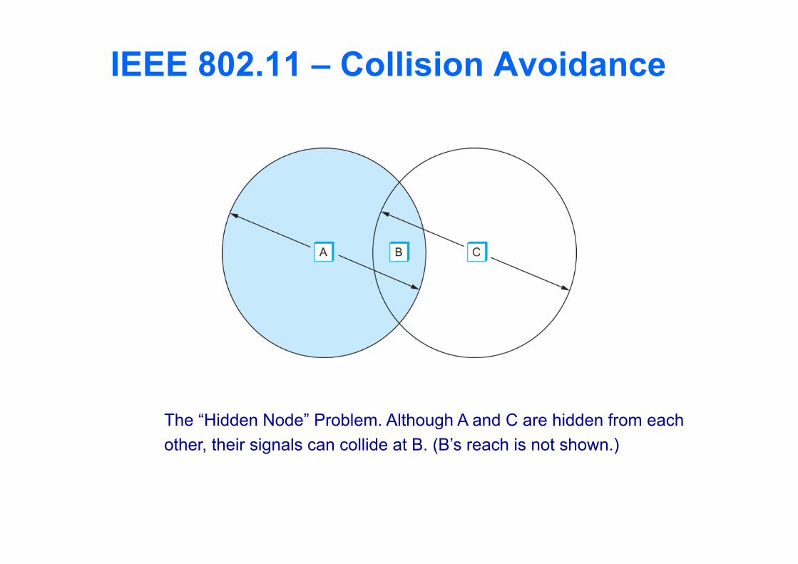
IEEE 802.11 – Collision Avoidance
The “Hidden Node” Problem. Although A and C are hidden from eachother, their signals can collide at B. (B’s reach is not shown.)
IEEE 802.11 – Collision Avoidance Another problem called exposed node problem occurs
Suppose B is sending to A. Node C is aware of this communication because it hears B’s transmission.
It would be a mistake for C to conclude that it cannot transmit to anyone just because it can hear B’s transmission.
Suppose C wants to transmit to node D. This is not a problem since C’s transmission to D will not interfere
with A’s ability to receive from B.
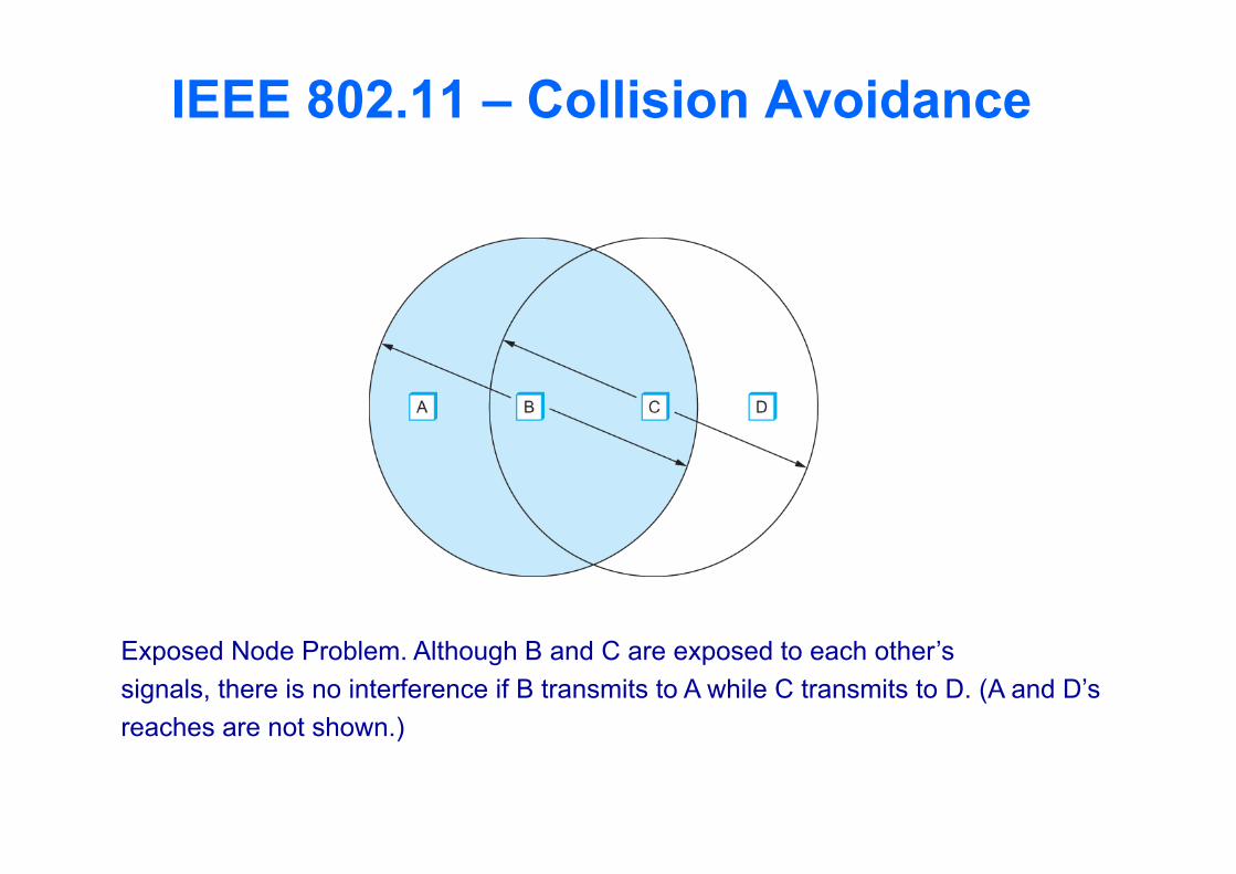
IEEE 802.11 – Collision Avoidance
Exposed Node Problem. Although B and C are exposed to each other’ssignals, there is no interference if B transmits to A while C transmits to D. (A and D’sreaches are not shown.)
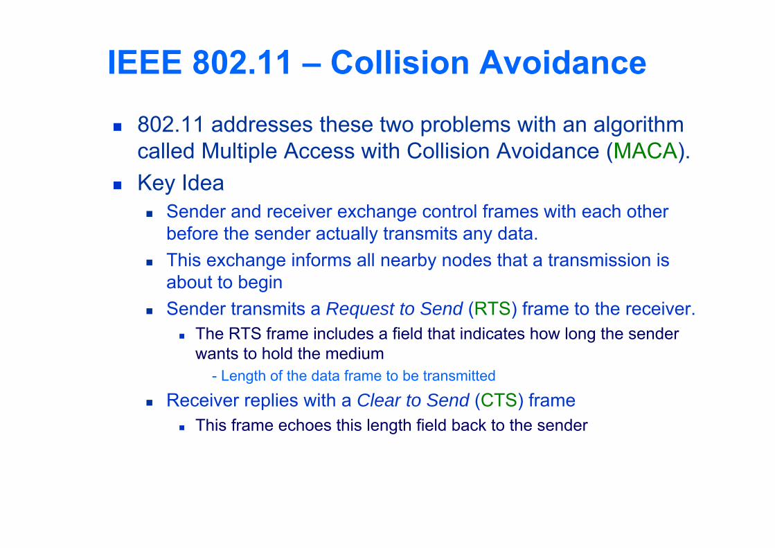
IEEE 802.11 – Collision Avoidance 802.11 addresses these two problems with an algorithm
called Multiple Access with Collision Avoidance (MACA). Key Idea
Sender and receiver exchange control frames with each other before the sender actually transmits any data.
This exchange informs all nearby nodes that a transmission is about to begin
Sender transmits a Request to Send (RTS) frame to the receiver. The RTS frame includes a field that indicates how long the sender
wants to hold the medium- Length of the data frame to be transmitted
Receiver replies with a Clear to Send (CTS) frame This frame echoes this length field back to the sender
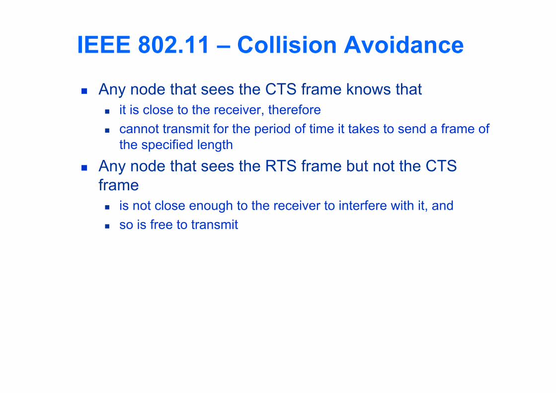
IEEE 802.11 – Collision Avoidance Any node that sees the CTS frame knows that
it is close to the receiver, therefore cannot transmit for the period of time it takes to send a frame of
the specified length Any node that sees the RTS frame but not the CTS
frame is not close enough to the receiver to interfere with it, and so is free to transmit
Copyright © 2010, Elsevier Inc.
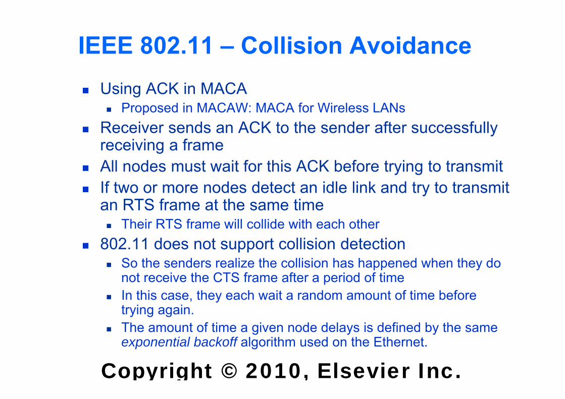
IEEE 802.11 – Collision Avoidance Using ACK in MACA
Proposed in MACAW: MACA for Wireless LANs Receiver sends an ACK to the sender after successfully
receiving a frame All nodes must wait for this ACK before trying to transmit If two or more nodes detect an idle link and try to transmit
an RTS frame at the same time Their RTS frame will collide with each other
802.11 does not support collision detection So the senders realize the collision has happened when they do
not receive the CTS frame after a period of time In this case, they each wait a random amount of time before
trying again. The amount of time a given node delays is defined by the same
exponential backoff algorithm used on the Ethernet.
Copyright © 2010, Elsevier Inc.
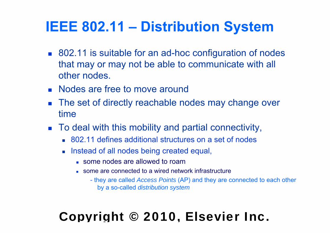
IEEE 802.11 – Distribution System 802.11 is suitable for an ad-hoc configuration of nodes
that may or may not be able to communicate with all other nodes.
Nodes are free to move around The set of directly reachable nodes may change over
time To deal with this mobility and partial connectivity,
802.11 defines additional structures on a set of nodes Instead of all nodes being created equal,
some nodes are allowed to roam some are connected to a wired network infrastructure
- they are called Access Points (AP) and they are connected to each other by a so-called distribution system
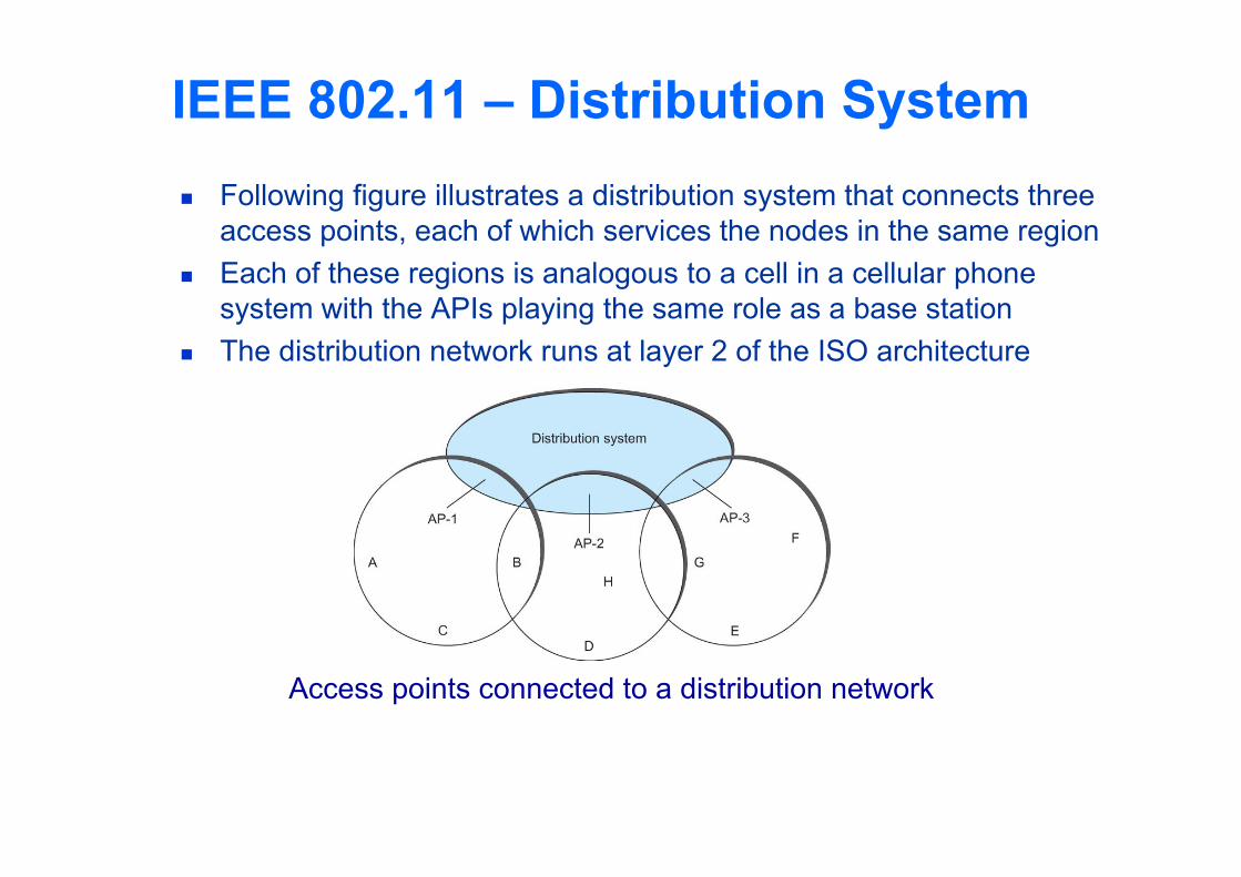
Following figure illustrates a distribution system that connects three access points, each of which services the nodes in the same region
Each of these regions is analogous to a cell in a cellular phone system with the APIs playing the same role as a base station
The distribution network runs at layer 2 of the ISO architecture
IEEE 802.11 – Distribution System
Access points connected to a distribution network
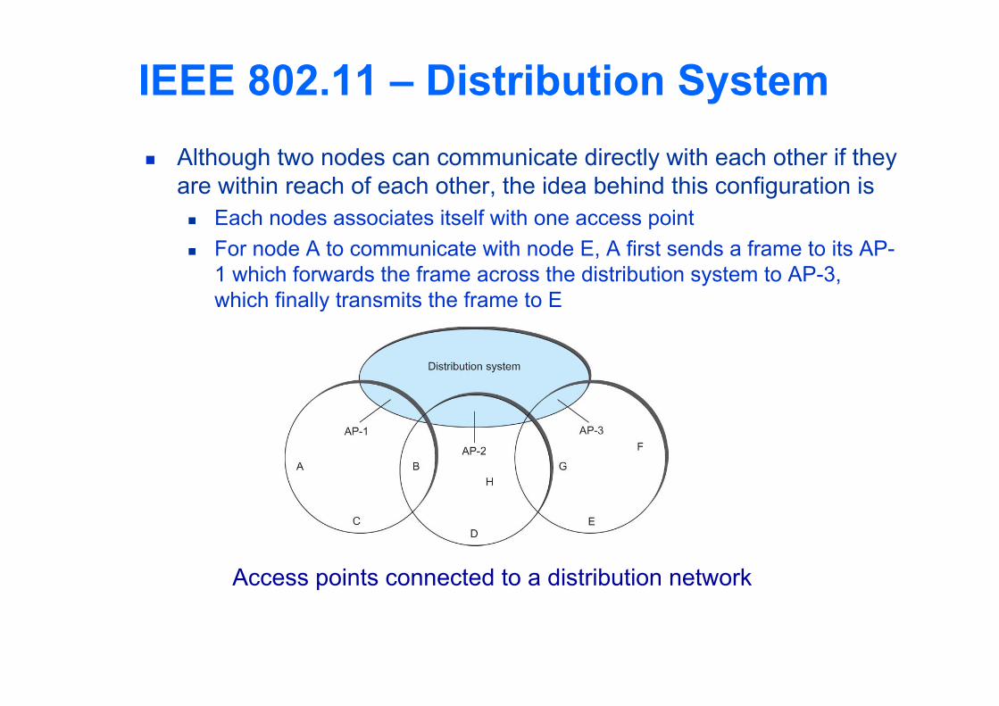
IEEE 802.11 – Distribution System Although two nodes can communicate directly with each other if they
are within reach of each other, the idea behind this configuration is Each nodes associates itself with one access point For node A to communicate with node E, A first sends a frame to its AP-
1 which forwards the frame across the distribution system to AP-3, which finally transmits the frame to E
Access points connected to a distribution network
Copyright © 2010, Elsevier Inc.
IEEE 802.11 – Distribution System How do the nodes select their access points How does it work when nodes move from one cell to another
The technique for selecting an AP is called scanning The node sends a Probe frame All APs within reach reply with a Probe Response frame The node selects one of the access points and sends that AP an
Association Request frame The AP replies with an Association Response frame
A node engages this protocol whenever it joins the network, as well as when it becomes unhappy with its current AP
This might happen, for example, because the signal from its current AP has weakened due to the node moving away from it
Whenever a node acquires a new AP, the new AP notifies the old AP of the change via the distribution system
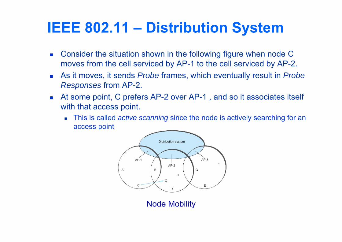
Consider the situation shown in the following figure when node C moves from the cell serviced by AP-1 to the cell serviced by AP-2.
As it moves, it sends Probe frames, which eventually result in Probe Responses from AP-2.
At some point, C prefers AP-2 over AP-1 , and so it associates itself with that access point. This is called active scanning since the node is actively searching for an
access point
IEEE 802.11 – Distribution System
Node Mobility
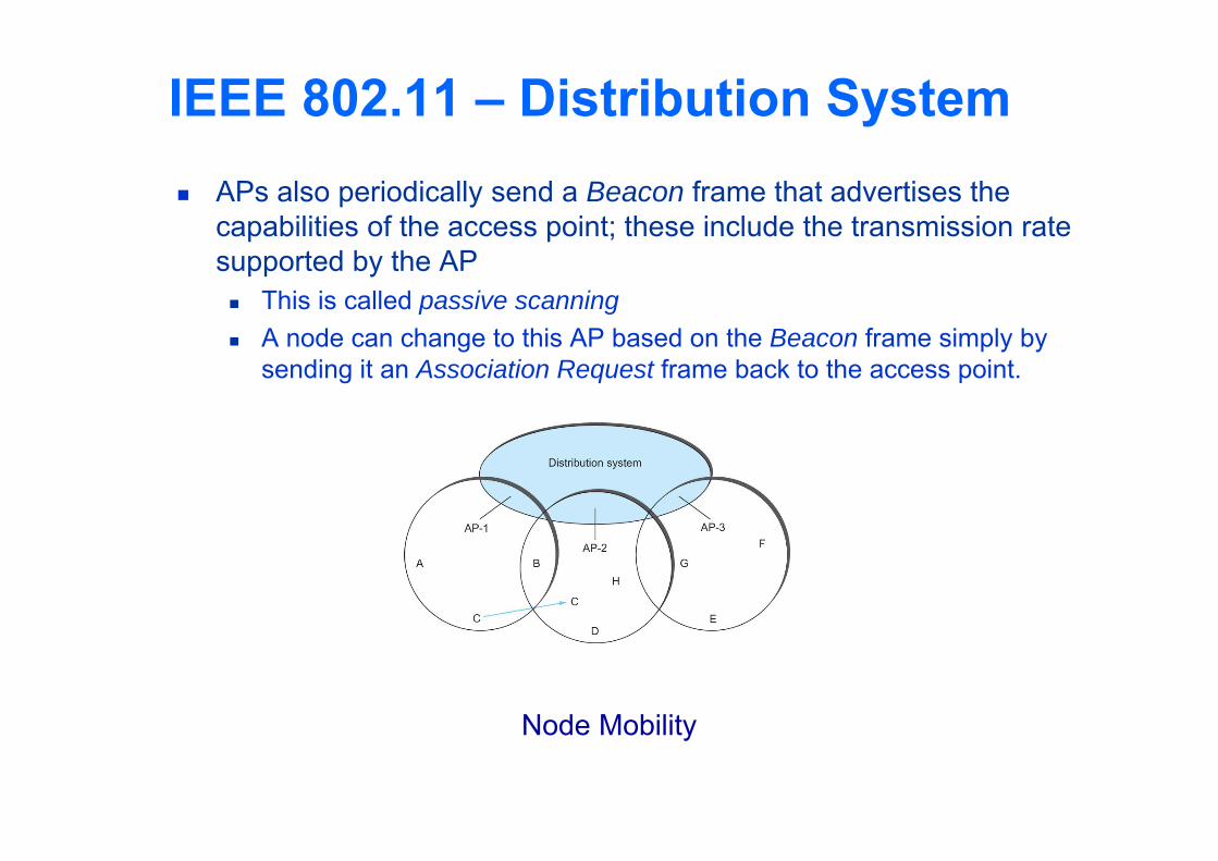
IEEE 802.11 – Distribution System APs also periodically send a Beacon frame that advertises the
capabilities of the access point; these include the transmission rate supported by the AP This is called passive scanning A node can change to this AP based on the Beacon frame simply by
sending it an Association Request frame back to the access point.
Node Mobility
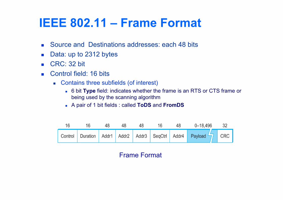
IEEE 802.11 – Frame Format Source and Destinations addresses: each 48 bits Data: up to 2312 bytes CRC: 32 bit Control field: 16 bits
Contains three subfields (of interest) 6 bit Type field: indicates whether the frame is an RTS or CTS frame or
being used by the scanning algorithm A pair of 1 bit fields : called ToDS and FromDS
Frame Format
IEEE 802.11 – Frame Format Frame contains four addresses How these addresses are interpreted depends on the settings of the
ToDS and FromDS bits in the frame’s Control field This is to account for the possibility that the frame had to be
forwarded across the distribution system which would mean that, the original sender is not necessarily the same as the most recent
transmitting node Same is true for the destination address Simplest case
When one node is sending directly to another, both the DS bits are 0, Addr1 identifies the target node, and Addr2 identifies the source node
IEEE 802.11 – Frame Format Most complex case
Both DS bits are set to 1 Indicates that the message went from a wireless node onto the distribution
system, and then from the distribution system to another wireless node With both bits set,
Addr1 identifies the ultimate destination, Addr2 identifies the immediate sender (the one that forwarded the frame
from the distribution system to the ultimate destination) Addr3 identifies the intermediate destination (the one that accepted the
frame from a wireless node and forwarded across the distribution system) Addr4 identifies the original source
Addr1: E, Addr2: AP-3, Addr3: AP-1, Addr4: A
Bluetooth Used for very short range communication between
mobile phones, PDAs, notebook computers and other personal or peripheral devices
Operates in the license-exempt band at 2.45 GHz Has a range of only 10 m Communication devices typically belong to one individual
or group Sometimes categorized as Personal Area Network (PAN)
Version 2.0 provides speeds up to 2.1 Mbps Power consumption is low
Copyright © 2010, Elsevier Inc.
Bluetooth Bluetooth is specified by an industry consortium called
the Bluetooth Special Interest Group It specifies an entire suite of protocols, going beyond the
link layer to define application protocols, which it calls profiles, for a range of applications There is a profile for synchronizing a PDA with personal
computer Another profile gives a mobile computer access to a wired LAN
The basic Bluetooth network configuration is called a piconet Consists of a master device and up to seven slave devices Any communication is between the master and a slave The slaves do not communicate directly with each other A slave can be parked: set to an inactive, low-power state
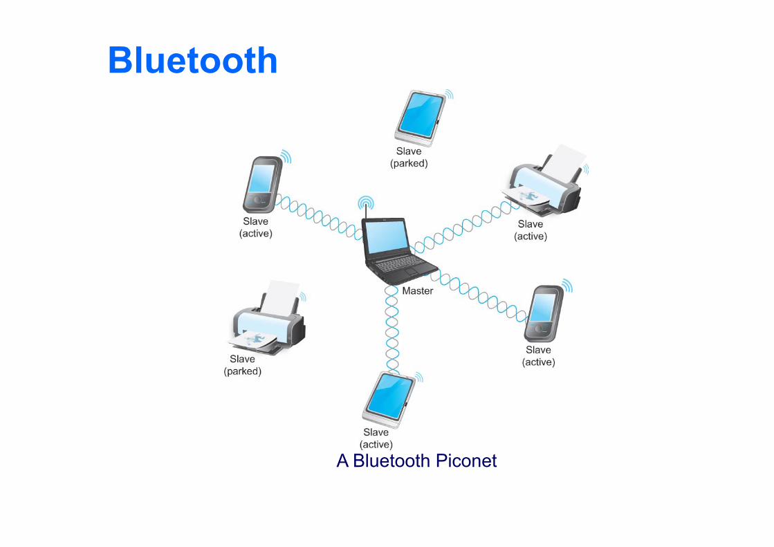
Bluetooth
A Bluetooth Piconet
ZigBee ZigBee is a new technology that competes with Bluetooth Devised by the ZigBee alliance and standardized as
IEEE 802.15.4 It is designed for situations where the bandwidth
requirements are low and power consumption must be very low to give very long battery life
It is also intended to be simpler and cheaper than Bluetooth, making it financially feasible to incorporate in cheaper devices such as a wall switch that wirelessly communicates with a ceiling-mounted fan
Summary We introduced the many and varied type of links that are
used to connect users to existing networks, and to construct large networks from scratch.
We looked at the five key issues that must be addressed so that two or more nodes connected by some medium can exchange messages with each other Encoding Framing Error Detecting Reliability Multiple Access Links
Ethernet Wireless 802.11, Bluetooth