Embed Size (px)
Citation preview
CTC Union Technologies Co., Ltd. HDSL Series
HDTU01/HRM01 i
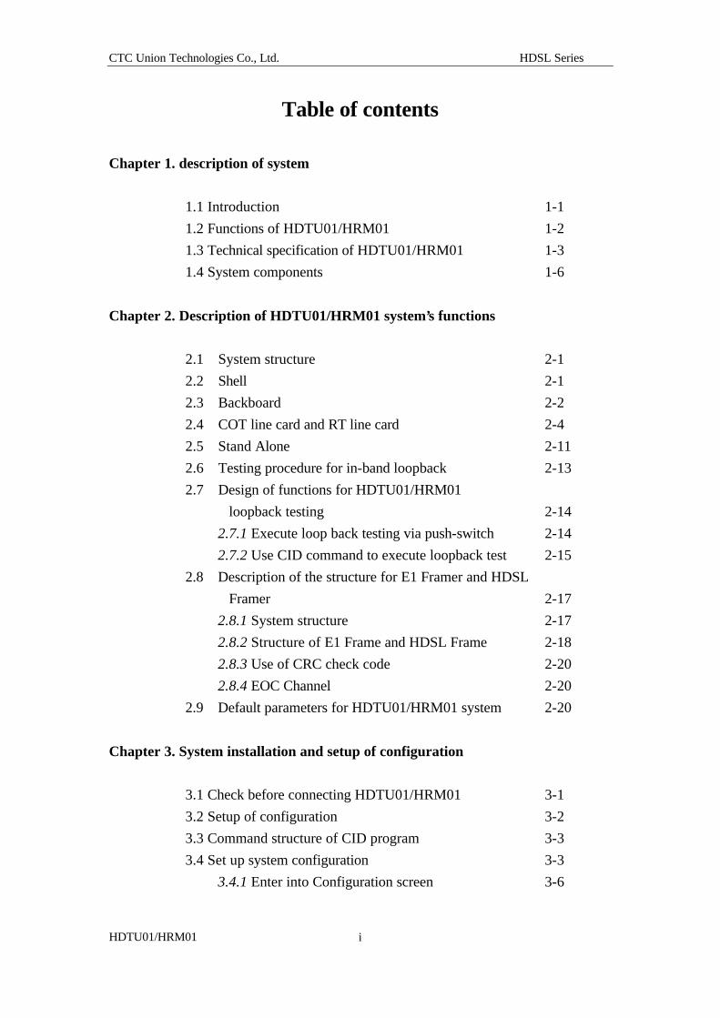
Table of contents
Chapter 1. description of system
1.1 Introduction 1-1
1.2 Functions of HDTU01/HRM01 1-2
1.3 Technical specification of HDTU01/HRM01 1-3
1.4 System components 1-6
Chapter 2. Description of HDTU01/HRM01 system’s functions
2.1 System structure 2-1
2.2 Shell 2-1
2.3 Backboard 2-2
2.4 COT line card and RT line card 2-4
2.5 Stand Alone 2-11
2.6 Testing procedure for in-band loopback 2-13
2.7 Design of functions for HDTU01/HRM01
loopback testing 2-14
2.7.1 Execute loop back testing via push-switch 2-14
2.7.2 Use CID command to execute loopback test 2-15
2.8 Description of the structure for E1 Framer and HDSL
Framer 2-17
2.8.1 System structure 2-17
2.8.2 Structure of E1 Frame and HDSL Frame 2-18
2.8.3 Use of CRC check code 2-20
2.8.4 EOC Channel 2-20
2.9 Default parameters for HDTU01/HRM01 system 2-20
Chapter 3. System installation and setup of configuration
3.1 Check before connecting HDTU01/HRM01 3-1
3.2 Setup of configuration 3-2
3.3 Command structure of CID program 3-3
3.4 Set up system configuration 3-3
3.4.1 Enter into Configuration screen 3-6
CTC Union Technologies Co., Ltd. HDSL Series
HDTU01/HRM01
ii
Chapter 4. System administration (Management)
4.1 Screen of system administration 4-1
4.1.1 Change system’s identification data 4-1
4.1.2 Modify user’s account of system 4-2
Chapter 5. System alarm and performance statistics
5.1 Alarm warning message 5-2
5.2 Performance statistics 5-4
5.2.1 Statistics of bits error for HDSL LOOP 5-5
5.2.2 Performance statistics for HDSL LOOP 5-6
5.2.3 E1 Statistics of signal’s bit error 5-7
5.3 Display status of front panel LED (Display LED) 5-8
5.4 Display the identity of system (Display Identity) 5-8
Chapter 6. System testing
6.1 HDSL LOOP test and E-1 interface test 6-1
6.2 Test major components (Device Tests) 6-2
6.3 Terminate all tests (Abort All test) 6-3
CTC Union Technologies Co., Ltd. HDSL Series
HDTU01/HRM01 1-1
Chapter 1. Description of system
1.1 Introduction
The HDTU01 is an HDSL (High-bit-rate Digital Subscriber Line) Access Unit
for E1 transmissions, available as a standalone 19" 1U rack unit or in card form for
insertion into the HRM01 HDSL 19" Rack Chassis. The HDTU 01 has model
configurations which support Fractional E1 for CO (Central Office) or CPE
(Customer Premises Equipment). The standalone HDTU 01 single unit is available in
both AC or DC-48V models. The HRM01 Rack Chassis requires a -48VDC source
and is capable of housing a total of 16 E1 cards or 15 E1cards and a single NMP
(management) card mix. The HDTU01 transmits signals at a distance of up to 4.0 km
(using 24AWG), over two pairs of copper wires with a data rate of 2.048Mbps.
Utilizing state-of-the-art design and technology, CTC Union's HDTU 01 is both
a cost effective and an ideal solution for INTERNET access connections, Base
Transceiver Station (BTS) connecting for cellular phone system, TI/El leased lines
extension, Nx64[56]Kb/s data services, SMDS ... etc..
HDTU 01 E1 HDSL 19” Stand Alone type is a complete system. You can
choose AC, DC model or remote power supply model, as shown below. You can
install the device in the standard 19” industrial machine cabinet or place it on a desk
or shelf.
19” Rack 5U Chassis and Line Cards 19” Rack 1U Standalone
CTC Union Technologies Co., Ltd. HDSL Series
HDTU01/HRM01 1-2
1.2 Functions of HDTU 01/HRM01
The primary function of the HDTU 01 is the transmission of 2.048 Mbits/s E1
signals. A large number of signals with E1 specification are used for the
establishment of telecommunication network. The conventional E1 signal uses AMI
or HDB3 line code, and the best transmission distance is limited to about 1.2KM.
Repeaters are utilized between circuits to increase transmission distance and facilitate
establishment of an E1 signal network. However, there are certain problems for the
installation of repeaters, such as the requirement of power supplies, roadwork, and the
accompanying difficulty of maintenance. These problems increase the cost of an E1
network and lengthen the time of construction and installation.
The HDTU 01 incorporates HDSL (High-bit-rate Digital Subscriber Line)
technology to transform E1 signals into HDSL signals by using CAP digital
modulation techniques. The signals can be transmitted as far as 4.0 kilometers over
two pairs of conventional 24AWG twisted wires (2.5KM over 26AWG wire pairs).
In many cases this extended range helps to meet the service distance between a
telecommunication central office and the end user. Since no repeater is needed, the
cost to establishment the network connection can be reduced significantly, and the
usage rate of wires can be improved tremendously. This technique may be applied to
either voice service or data service.
HDTU 01 E1 HDSL Features: l Complies with ITU-T G.991.1 and ETSI ETR 152 HDSL standards.
l E1 interface complies with ITU-T G.703 and G.704 standards.
l When connected with 0.4 mm (26 AWG) twisted pairs and subjected to a certain level of noise
disturbance, the signal can be transmitted for up to 2.5 kilometers. Without any disturbance, the
transmission distance can be extended up to 3.6 kilometers with a BER (Bit Error Rate) of less
than 10^ -7.
l Supports the transmission of Fractional E1 signals.
l The line code for E1 signal can be either AMI or HDB3.
l HDSL employs the 64-CAP modulation method.
l Built-in generating unit and reception unit for QRSS and 2^15-1 PRBS test patterns, allow the
system to conduct self-diagnostics.
l Built-in 16 bits programmable loop-back code executes In-band loop-back tests.
l Each 19” HRM 01 chassis can accommodate up to 16 cards, including 1 Network Management
Protocol (NMP). The user may also perform network management functions in conjunction with
the corresponding proprietary Windows™ based Network Management System.
CTC Union Technologies Co., Ltd. HDSL Series
HDTU01/HRM01 1-3
l If the two loops of HDSL are cross-connected, the system will detect and adjust for normal
operation.
l The wire length of the two loops of HDSL may be different. The system still maintains normal
operation if the difference between the wire lengths is less than 1 kilometer.
l The synchronization sources of the system include E1 input signal recovery, internal clock and
external clock modes.
The HDTU 01 product may be applied to the signal transmission of E1 or
fractional E1 (FE1), such as the signal transmission between Base Transceiver
Stations of the cellular network system, or between telecommunication stations, or the
digital signal transmission between the telecommunication central offices and the
users in hi-rise.
The major function of HDTU 01 is to transform E1 or FE1 signals into HDSL
signals, and then transmit signals to the other end via the loops constituted by the two
twisted-pair wires. The system design of CAP modulation for HDSL can guarantee
higher quality of transmission. The HDTU 01 system equipped with various testing
and monitor functions (OAM&P) which is connected with VT 100 or compatible
terminal simulation program via the CID interface (RS-232 interface) of the line card
or standalone type also allow on-site engineers to maintain and administer the system.
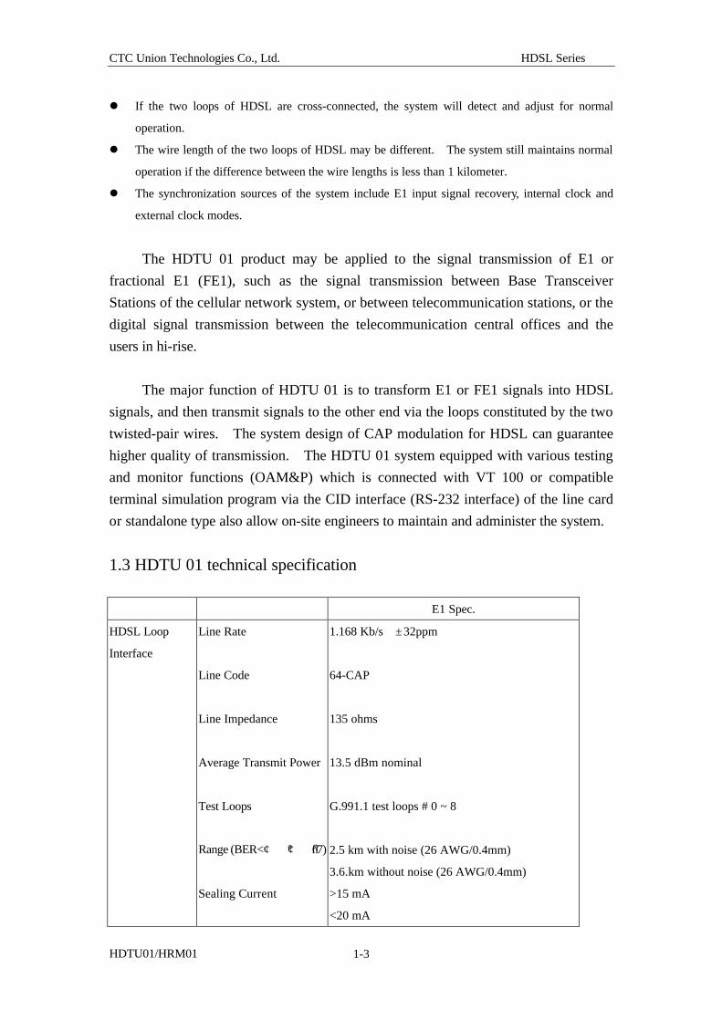
1.3 HDTU 01 technical specification E1 Spec.
HDSL Loop
Interface
Line Rate
Line Code
Line Impedance
Average Transmit Power
Test Loops
Range (BER<¢ °¢ ¯̂7)
Sealing Current
1.168 Kb/s ± 32ppm
64-CAP
135 ohms
13.5 dBm nominal
G.991.1 test loops # 0 ~ 8
2.5 km with noise (26 AWG/0.4mm)
3.6.km without noise (26 AWG/0.4mm)
>15 mA
<20 mA
CTC Union Technologies Co., Ltd. HDSL Series
HDTU01/HRM01 1-4
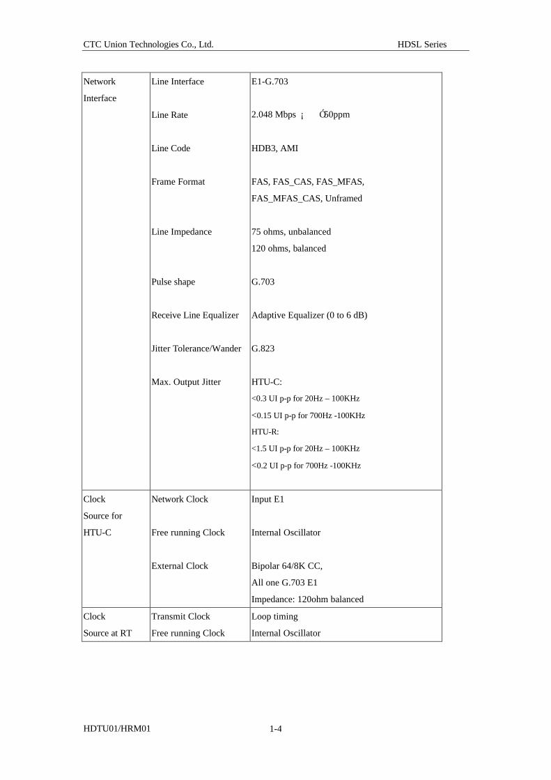
Network
Interface
Line Interface
Line Rate
Line Code
Frame Format
Line Impedance
Pulse shape
Receive Line Equalizer
Jitter Tolerance/Wander
Max. Output Jitter
E1-G.703
2.048 Mbps ¡ Ó 50ppm
HDB3, AMI
FAS, FAS_CAS, FAS_MFAS,
FAS_MFAS_CAS, Unframed
75 ohms, unbalanced
120 ohms, balanced
G.703
Adaptive Equalizer (0 to 6 dB)
G.823
HTU-C:
<0.3 UI p-p for 20Hz – 100KHz
<0.15 UI p-p for 700Hz -100KHz
HTU-R:
<1.5 UI p-p for 20Hz – 100KHz
<0.2 UI p-p for 700Hz -100KHz
Clock
Source for
HTU-C
Network Clock
Free running Clock
External Clock
Input E1
Internal Oscillator
Bipolar 64/8K CC,
All one G.703 E1
Impedance: 120ohm balanced
Clock
Source at RT
Transmit Clock
Free running Clock
Loop timing
Internal Oscillator
CTC Union Technologies Co., Ltd. HDSL Series
HDTU01/HRM01 1-5
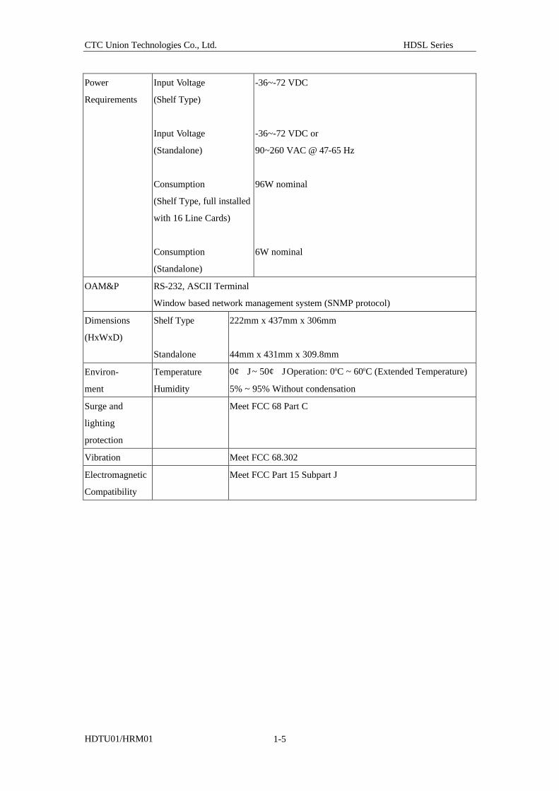
Power
Requirements
Input Voltage
(Shelf Type)
Input Voltage
(Standalone)
Consumption
(Shelf Type, full installed
with 16 Line Cards)
Consumption
(Standalone)
-36~-72 VDC
-36~-72 VDC or
90~260 VAC @ 47-65 Hz
96W nominal
6W nominal
OAM&P RS-232, ASCII Terminal
Window based network management system (SNMP protocol)
Dimensions
(HxWxD)
Shelf Type
Standalone
222mm x 437mm x 306mm
44mm x 431mm x 309.8mm
Environ-
ment
Temperature
Humidity
0¢ J ~ 50¢ J Operation: 00C ~ 600C (Extended Temperature)
5% ~ 95% Without condensation
Surge and
lighting
protection
Meet FCC 68 Part C
Vibration Meet FCC 68.302
Electromagnetic
Compatibility
Meet FCC Part 15 Subpart J
CTC Union Technologies Co., Ltd. HDSL Series
HDTU01/HRM01 1-6
1.4 System components The HDTU 01 system components include:
1. The 19” shelf to accommodate up to 16 pieces of HDSL line cards, or 15 pieces
of line cards and 1 MCU card.
2. The back board, which is installed behind the shelf, to provide various connection
interfaces and power input connectors.
3. The HDTU 01 E1 HDSL line card. The types of line card include the central
office’s line car d (known as COT or LTU) and remote terminal line card (known
as RT or NTU). The following sections of this manual will describe COT line
card and RT line card. COT line card and RT line card are different in program
design. Please specify when you order.
COT line card and RT line card mainly consist of Line Control Board and
transmission unit (XCVR). The line card’s front panel provides following
maintenance and testing functions:
l E1 testing interface (Bantam Jack): use this testing interface to
separate line card for testing diagnosis.
l LED status display: determine the system’s operation based on the
status displayed by LED.
l Button for Loopback testing: front panel provides two buttons for
loopback testing for local loopback testing and remote loopback
testing.
l CID interface: connects personal computer’s R S-232 serial
interface and uses VT-100 terminal simulation program for system
administration.
4. The MCU possesses CID interface and Ethernet LAN interface. CID is a RJ-45
connector to connect the RS-232 interface of PC for system administration. The
correspondence chart showing the pin configuration converting RJ-45 to 9-Pin or
25-pin will be illustrated in chapter 2.
5. 19” Stand Alone type’s E1 HDSL includes a 19” shell containing a set of E1
HDSL line card. This product has a different package. However, its functions
are the same as that of E1 HDSL. The front panel is equipped with LED
indicator and CID interface. The back board is for the connection of E1 interface
and HDSL signal. Generally, the line card uses AC 110 V/220V 60Hz. If you
use DC-48V power input, you need to specify it when you order.
CTC Union Technologies Co., Ltd. HDSL Series
HDTU01/HRM01 1-7
6. Network management system (Pulsar EMS)
You can purchase the network management system for administration of the entire
machine’s line card. The Pulsar EMS is designed in compliance with the
specification of network management system of SNMP. This system operates
under Windows NT/98/95 and executes Pulsar EMS via the Ethernet LAN of the
MCU. This system also administers entire E1 HDSL system and controls the
working status of each line card through statistics and numerical analysis.
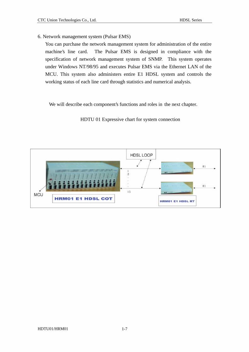
We will describe each component’s functions and roles in the next chapter.
HDTU 01 Expressive chart for system connection
CTC Union Technologies Co., Ltd. HDSL Series
HDTU01/HRM01 2-1
Chapter 2. Description of HDTU01/HRM01 system’s functions
2-1 System structure
To help users build up a complete understanding about the HDTU01/HRM01
system, this chapter introduces the functions of all units of HDTU01/HRM01 system
and the structure of E1 Frame and HDSL Frame, and describes how to use certain bits
for system administration, thereby allows you to obtain basic understanding about the
principles of the HDTU01/HRM01 system.
This chapter contains two parts. The first part introduces the system’s
hardware structure including description of all interfaces. The second part describes
the structures of E1 Frame and HDSL Frame, definition of all bytes of EOC Channel,
as well as the operation procedure of Smart Jack (in-band loop back test) and Loop
Back.
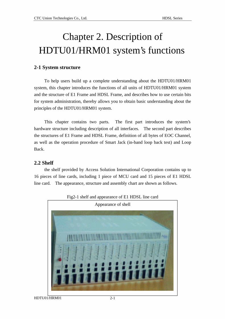
2.2 Shelf the shelf provided by Access Solution International Corporation contains up to
16 pieces of line cards, including 1 piece of MCU card and 15 pieces of E1 HDSL
line card. The appearance, structure and assembly chart are shown as follows.
Fig2-1 shelf and appearance of E1 HDSL line card
Appearance of shell
CTC Union Technologies Co., Ltd. HDSL Series
HDTU01/HRM01 2-2
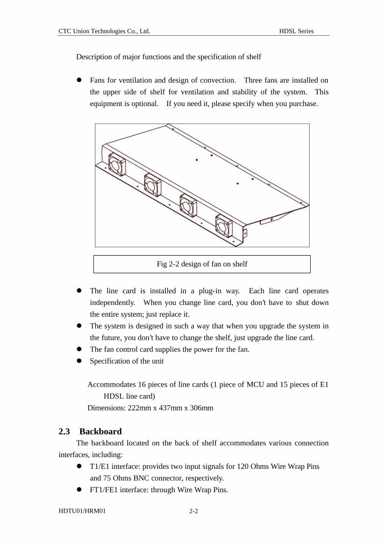
Description of major functions and the specification of shelf
l Fans for ventilation and design of convection. Three fans are installed on
the upper side of shelf for ventilation and stability of the system. This
equipment is optional. If you need it, please specify when you purchase.
l The line card is installed in a plug-in way. Each line card operates
independently. When you change line card, you don’t have to shut down
the entire system; just replace it.
l The system is designed in such a way that when you upgrade the system in
the future, you don’t have to change the shelf, just upgrade the line card.
l The fan control card supplies the power for the fan.
l Specification of the unit
Accommodates 16 pieces of line cards (1 piece of MCU and 15 pieces of E1
HDSL line card)
Dimensions: 222mm x 437mm x 306mm
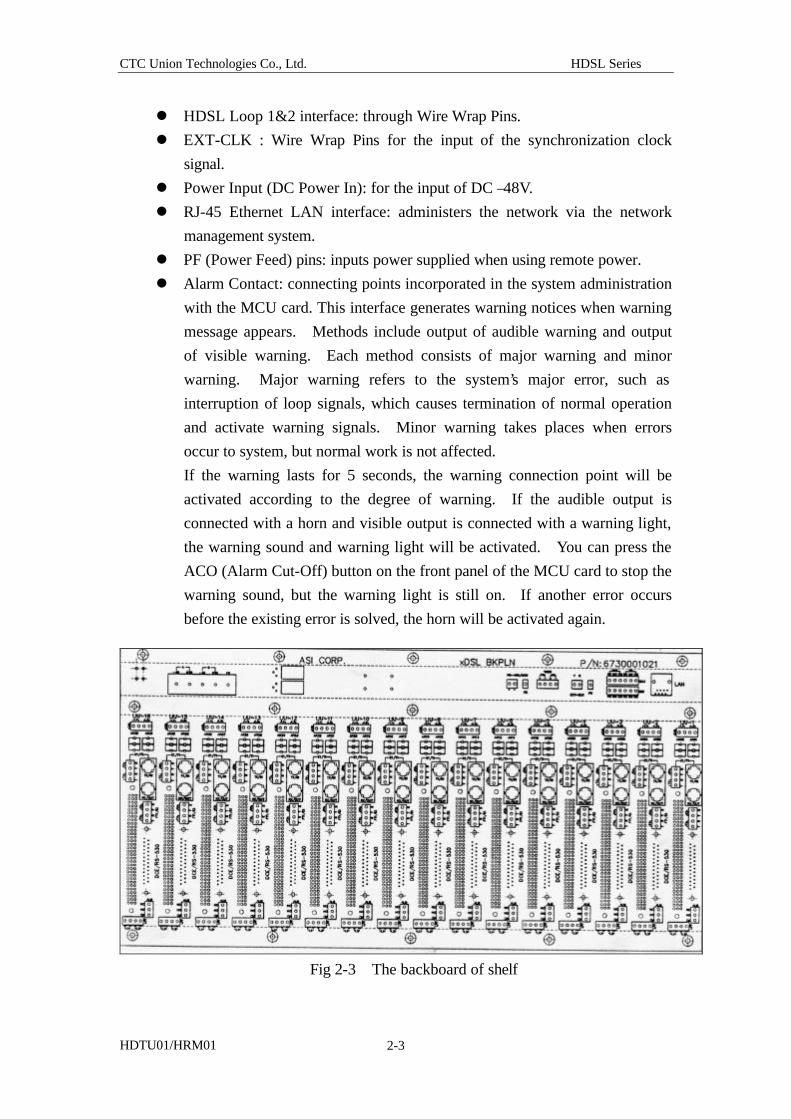
2.3 Backboard The backboard located on the back of shelf accommodates various connection
interfaces, including:
l T1/E1 interface: provides two input signals for 120 Ohms Wire Wrap Pins
and 75 Ohms BNC connector, respectively.
l FT1/FE1 interface: through Wire Wrap Pins.
Fig 2-2 design of fan on shelf
CTC Union Technologies Co., Ltd. HDSL Series
HDTU01/HRM01 2-3
l HDSL Loop 1&2 interface: through Wire Wrap Pins.
l EXT-CLK : Wire Wrap Pins for the input of the synchronization clock
signal.
l Power Input (DC Power In): for the input of DC –48V.
l RJ-45 Ethernet LAN interface: administers the network via the network
management system.
l PF (Power Feed) pins: inputs power supplied when using remote power.
l Alarm Contact: connecting points incorporated in the system administration
with the MCU card. This interface generates warning notices when warning
message appears. Methods include output of audible warning and output
of visible warning. Each method consists of major warning and minor
warning. Major warning refers to the system’s major error, such as
interruption of loop signals, which causes termination of normal operation
and activate warning signals. Minor warning takes places when errors
occur to system, but normal work is not affected.
If the warning lasts for 5 seconds, the warning connection point will be
activated according to the degree of warning. If the audible output is
connected with a horn and visible output is connected with a warning light,
the warning sound and warning light will be activated. You can press the
ACO (Alarm Cut-Off) button on the front panel of the MCU card to stop the
warning sound, but the warning light is still on. If another error occurs
before the existing error is solved, the horn will be activated again.
Fig 2-3 The backboard of shelf
CTC Union Technologies Co., Ltd. HDSL Series
HDTU01/HRM01 2-4
The wire wrap pins of E1 and HDSL LOOP connect 246 AWG(0.4m/m) or 24
AWG(0.6 m/m) cable by knitting. In the next chapter, we will describe the
installation. The backboard is locked on the shelf. Under the normal
circumstances, users do not have to disassemble it. If users need to repair due to
malfunction, they may unscrew the screws around the backboard to remove the
backboard.
To plug in the card, insert the line card into the track on the front of shelf and
push it into the connection chute of the backboard. The motion to remove the line
card is reversal.
2.4 COT line card and RT line card
The HDTU01/HRM01 system works in pair. The customer side is called RT
(Remote Terminal). The telecommunication office’s side is called COT (Central
Office Terminal). This section covers the functions of RT side line card and COT
side line card. As we mentioned in the previous section, line cards can be installed
in a 19” shelf or shell of 19” stand alone type. We can observe the system’s
operation status by the LED indication on the board.
CTC Union Technologies Co., Ltd. HDSL Series
HDTU01/HRM01 2-5
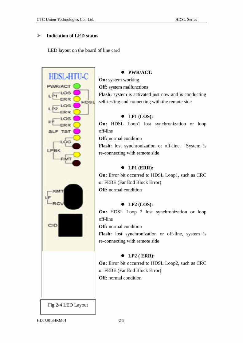
Ø Indication of LED status
LED layout on the board of line card
l PWR/ACT:
On: system working
Off: system malfunctions
Flash: system is activated just now and is conducting
self-testing and connecting with the remote side
l LP1 (LOS):
On: HDSL Loop1 lost synchronization or loop
off-line
Off: normal condition
Flash: lost synchronization or off-line. System is
re-connecting with remote side
l LP1 (ERR):
On: Error bit occurred to HDSL Loop1, such as CRC
or FEBE (Far End Block Error)
Off: normal condition
l LP2 (LOS):
On: HDSL Loop 2 lost synchronization or loop
off-line
Off: normal condition
Flash: lost synchronization or off-line, system is
re-connecting with remote side
l LP2 ( ERR):
On: Error bit occurred to HDSL Loop2, such as CRC
or FEBE (Far End Block Error)
Off: normal condition
Fig 2-4 LED Layout
CTC Union Technologies Co., Ltd. HDSL Series
HDTU01/HRM01 2-6
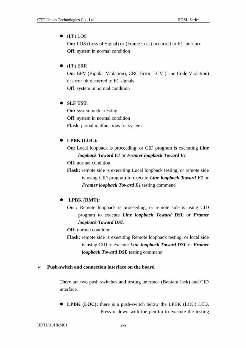
l (I/F) LOS
On: LOS (Loss of Signal) or (Frame Loss) occurred to E1 interface
Off: system in normal condition
l (I/F) ERR
On: BPV (Bipolar Violation), CRC Error, LCV (Line Code Violation)
or error bit occurred to E1 signals
Off: system in normal condition
l SLF TST:
On: system under testing
Off: system in normal condition
Flash: partial malfunctions for system
l LPBK (LOC):
On: Local loopback is proceeding, or CID program is executing Line
loopback Toward E1 or Framer loopback Toward E1
Off: normal condition
Flash: remote side is executing Local loopback testing, or remote side
is using CID program to execute Line loopback Toward E1 or
Framer loopback Toward E1 testing command
l LPBK (RMT):
On : Remote loopback is proceeding, or remote side is using CID
program to execute Line loopback Toward DSL or Framer
loopback Toward DSL
Off: normal condition
Flash: remote side is executing Remote loopback testing, or local side
is using CID to execute Line loopback Toward DSL or Framer
loopback Toward DSL testing command
Ø Push-switch and connection interface on the board
There are two push-switches and testing interface (Bantam Jack) and CID
interface.
l LPBK (LOC): there is a push-switch below the LPBK (LOC) LED.
Press it down with the pen-tip to execute the testing
CTC Union Technologies Co., Ltd. HDSL Series
HDTU01/HRM01 2-7
function of local loopback. When this button is
pressed down, the local side’s LPBK (LOC) LED will
be on. The remote side’s LPBK (LOC) LED fla shes.
l LPBK (RMT): there s a push-switch below the LPBK (RMT) LED.
Press it down with the pen-tip to execute Remote
Loopback. When you press down this button, the
system will request the to reflect the received signals
back. The LPBK (RMT) LED at the remote side
flashes. The remote system’s E1 Framer sends out
AIS Code to advise the system connecting with it.
l HDSL LP1/LP2 function or IF XMT/RCV function:
Provides Bantan Jack testing interface. Also provides
two versions of function design. The standard version is
Interface Break (“IF XMT/RCV” is marked on the panel)
and the option version is Loop Break (“HDSL LP1/LP2” is
marked on the panel). Specify it when you order. The
functions for these two versions are as follows:
(1) HDSL Loop Break: insert testing plugs to separate the
line card and HDSL Loop circuit. The testing signal
can be imprinted on HDSL Loop for testing with remote
side.
(2) E1 Interface Break: insert testing plugs to separate the
E1 signal imprinted on the line card. The testing signal
can be imprinted via line card’s E1 input pin for testing.
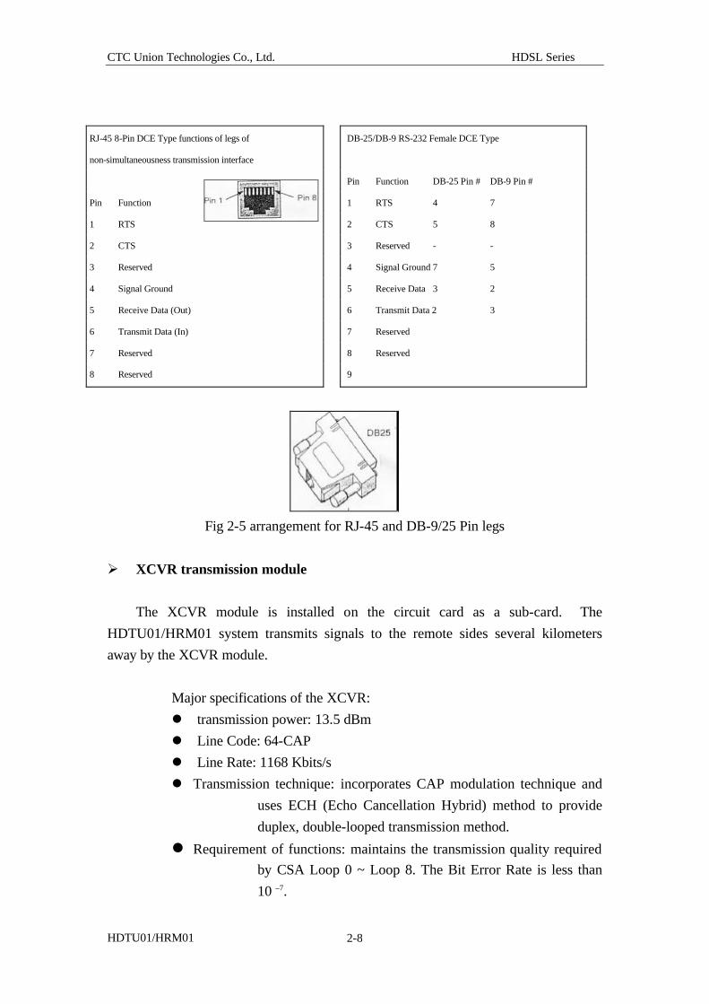
l CID: connector of 8-Pin RJ-45. The other side connects computer’s
RS-232 interface by DB-9/25 Female connector. The CID
executes VT-100 terminal program, and adjust or sets up system
configuration.
Arrangement of the Pins for CID RJ 45 and DB-9/25 is shown as
the following chart.
CTC Union Technologies Co., Ltd. HDSL Series
HDTU01/HRM01 2-8
Fig 2-5 arrangement for RJ-45 and DB-9/25 Pin legs
Ø XCVR transmission module
The XCVR module is installed on the circuit card as a sub-card. The
HDTU01/HRM01 system transmits signals to the remote sides several kilometers
away by the XCVR module.
Major specifications of the XCVR:
l transmission power: 13.5 dBm
l Line Code: 64-CAP
l Line Rate: 1168 Kbits/s
l Transmission technique: incorporates CAP modulation technique and
uses ECH (Echo Cancellation Hybrid) method to provide
duplex, double-looped transmission method.
l Requirement of functions: maintains the transmission quality required
by CSA Loop 0 ~ Loop 8. The Bit Error Rate is less than
10 –7.
RJ-45 8-Pin DCE Type functions of legs of
non-simultaneousness transmission interface
Pin Function
1 RTS
2 CTS
3 Reserved
4 Signal Ground
5 Receive Data (Out)
6 Transmit Data (In)
7 Reserved
8 Reserved
DB-25/DB-9 RS-232 Female DCE Type
Pin Function DB-25 Pin # DB-9 Pin #
1 RTS 4 7
2 CTS 5 8
3 Reserved - -
4 Signal Ground 7 5
5 Receive Data 3 2
6 Transmit Data 2 3
7 Reserved
8 Reserved
9
CTC Union Technologies Co., Ltd. HDSL Series
HDTU01/HRM01 2-9
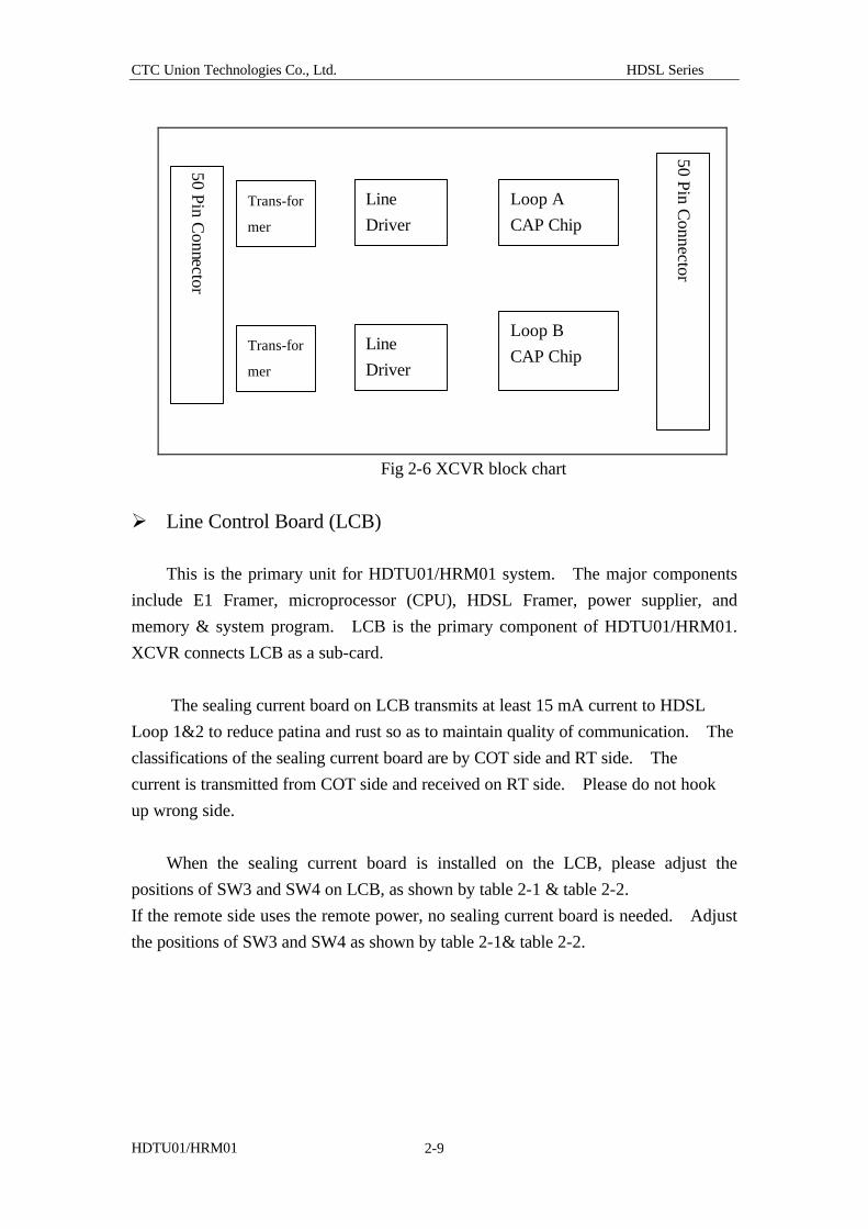
Fig 2-6 XCVR block chart
Ø Line Control Board (LCB)
This is the primary unit for HDTU01/HRM01 system. The major components
include E1 Framer, microprocessor (CPU), HDSL Framer, power supplier, and
memory & system program. LCB is the primary component of HDTU01/HRM01.
XCVR connects LCB as a sub-card.
The sealing current board on LCB transmits at least 15 mA current to HDSL
Loop 1&2 to reduce patina and rust so as to maintain quality of communication. The
classifications of the sealing current board are by COT side and RT side. The
current is transmitted from COT side and received on RT side. Please do not hook
up wrong side.
When the sealing current board is installed on the LCB, please adjust the
positions of SW3 and SW4 on LCB, as shown by table 2-1 & table 2-2.
If the remote side uses the remote power, no sealing current board is needed. Adjust
the positions of SW3 and SW4 as shown by table 2-1& table 2-2.
50 Pin Connector
50 Pin Connector
Line
Driver
Loop A
CAP Chip
Line
Driver
Loop B
CAP Chip
Trans-for
mer
Trans-for
mer
CTC Union Technologies Co., Ltd. HDSL Series
HDTU01/HRM01 2-10
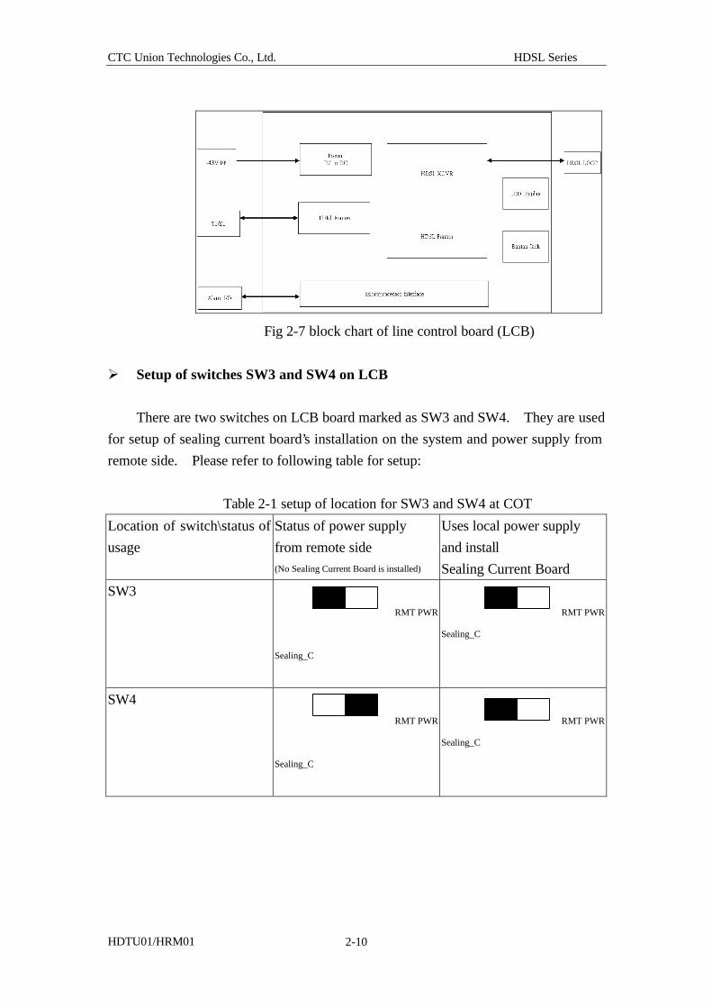
Fig 2-7 block chart of line control board (LCB)
Ø Setup of switches SW3 and SW4 on LCB
There are two switches on LCB board marked as SW3 and SW4. They are used
for setup of sealing current board’s installation on the system and power supply from
remote side. Please refer to following table for setup:
Table 2-1 setup of location for SW3 and SW4 at COT
Location of switch\status of
usage
Status of power supply
from remote side (No Sealing Current Board is installed)
Uses local power supply
and install
Sealing Current Board
SW3
RMT PWR
Sealing_C
RMT PWR
Sealing_C
SW4
RMT PWR
Sealing_C
RMT PWR
Sealing_C
CTC Union Technologies Co., Ltd. HDSL Series
HDTU01/HRM01 2-11
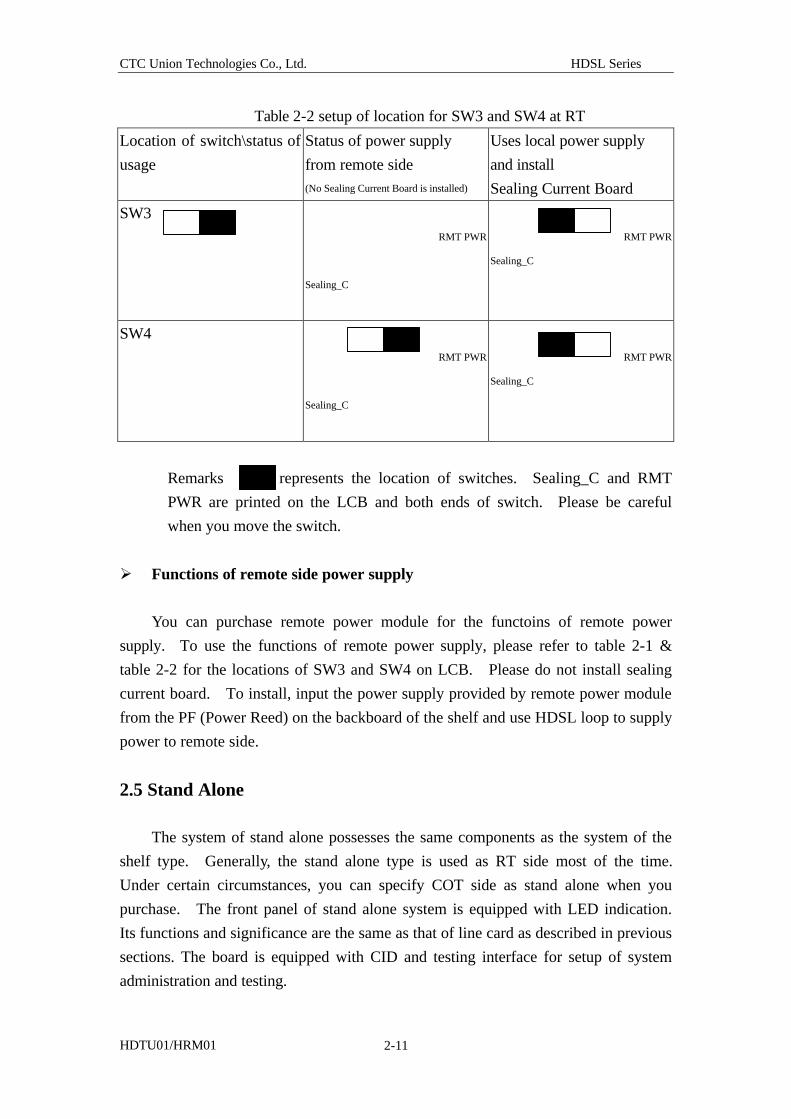
Table 2-2 setup of location for SW3 and SW4 at RT
Location of switch\status of
usage
Status of power supply
from remote side (No Sealing Current Board is installed)
Uses local power supply
and install
Sealing Current Board
SW3
RMT PWR
Sealing_C
RMT PWR
Sealing_C
SW4
RMT PWR
Sealing_C
RMT PWR
Sealing_C
Remarks represents the location of switches. Sealing_C and RMT
PWR are printed on the LCB and both ends of switch. Please be careful
when you move the switch.
Ø Functions of remote side power supply
You can purchase remote power module for the functoins of remote power
supply. To use the functions of remote power supply, please refer to table 2-1 &
table 2-2 for the locations of SW3 and SW4 on LCB. Please do not install sealing
current board. To install, input the power supply provided by remote power module
from the PF (Power Reed) on the backboard of the shelf and use HDSL loop to supply
power to remote side.
2.5 Stand Alone
The system of stand alone possesses the same components as the system of the
shelf type. Generally, the stand alone type is used as RT side most of the time.
Under certain circumstances, you can specify COT side as stand alone when you
purchase. The front panel of stand alone system is equipped with LED indication.
Its functions and significance are the same as that of line card as described in previous
sections. The board is equipped with CID and testing interface for setup of system
administration and testing.
CTC Union Technologies Co., Ltd. HDSL Series
HDTU01/HRM01 2-12
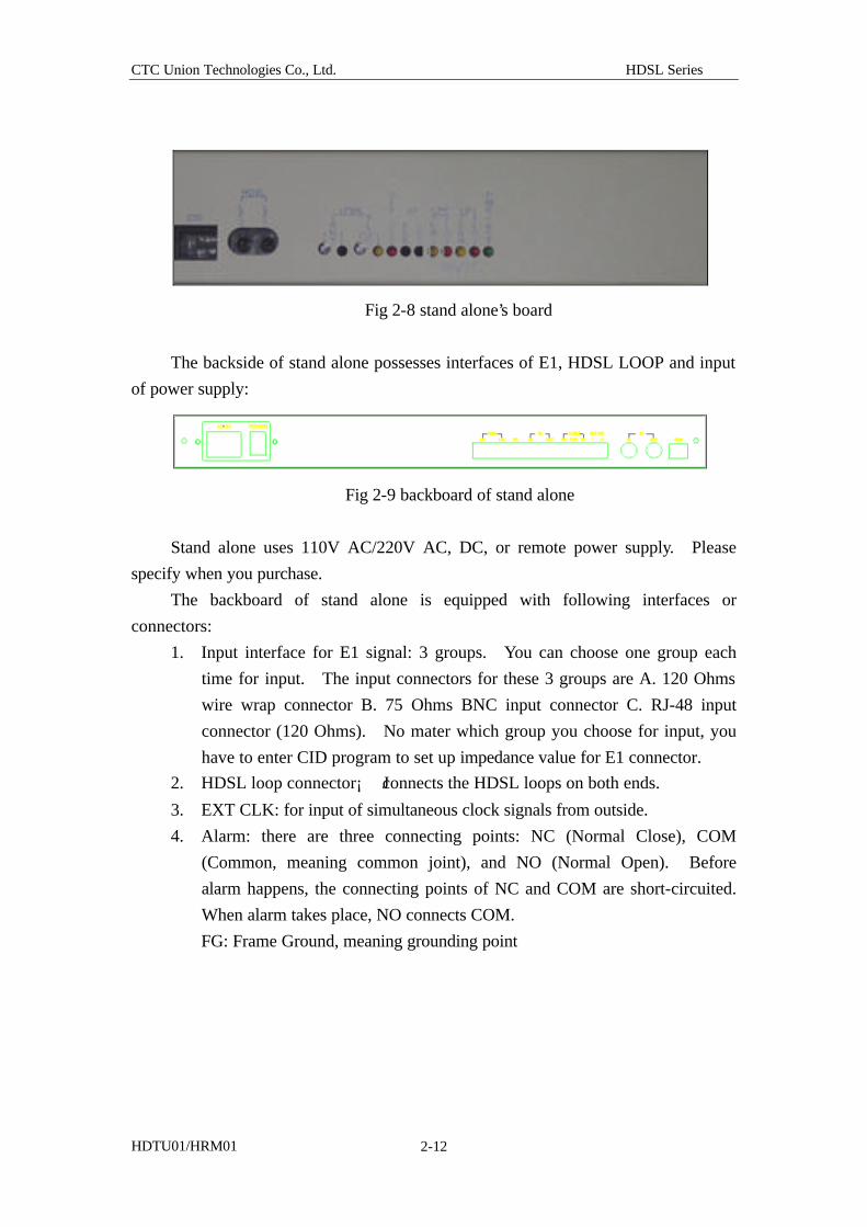
Fig 2-8 stand alone’s board
The backside of stand alone possesses interfaces of E1, HDSL LOOP and input
of power supply:
Fig 2-9 backboard of stand alone
Stand alone uses 110V AC/220V AC, DC, or remote power supply. Please
specify when you purchase.
The backboard of stand alone is equipped with following interfaces or
connectors:
1. Input interface for E1 signal: 3 groups. You can choose one group each
time for input. The input connectors for these 3 groups are A. 120 Ohms
wire wrap connector B. 75 Ohms BNC input connector C. RJ-48 input
connector (120 Ohms). No mater which group you choose for input, you
have to enter CID program to set up impedance value for E1 connector.
2. HDSL loop connector¡ Jconnects the HDSL loops on both ends.
3. EXT CLK: for input of simultaneous clock signals from outside.
4. Alarm: there are three connecting points: NC (Normal Close), COM
(Common, meaning common joint), and NO (Normal Open). Before
alarm happens, the connecting points of NC and COM are short-circuited.
When alarm takes place, NO connects COM.
FG: Frame Ground, meaning grounding point
CTC Union Technologies Co., Ltd. HDSL Series
HDTU01/HRM01 2-13
2.6 Testing procedure for in-band loopbacck
HDTU01/HRM01 system allows the program to monitor continuously the
command for execution of in-band loop testing transmitted by telecommunication
service company via E1 interface. This is a string of special codes. When system
detects codes with such format, the program requests COT and RT sides to enter
ARM (alarm) status. If program detects following code format, it will request NTU
or LTU to enter into LOOP-UP status:
COT side : 1101 0011 1101 0011
RT side : 1101 0111 0100 0010
For example, this is the code format being detected: 1101 0111 0100 0010.
RT side enters LOOP-UP status and starts executing loop testing. Signals enter COT
side, passes through HDSL LOOP, then return to the sender’s side from E1 Framer of
RT side. This test will help you to clarity the problem and determine the source of
problem.
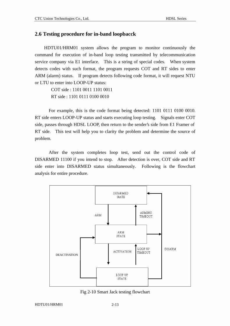
After the system completes loop test, send out the control code of
DISARMED 11100 if you intend to stop. After detection is over, COT side and RT
side enter into DISARMED status simultaneously. Following is the flowchart
analysis for entire procedure.
Fig 2-10 Smart Jack testing flowchart
DEACTIVATION
CTC Union Technologies Co., Ltd. HDSL Series
HDTU01/HRM01 2-14
2.7 Design of functions for HDTU01/HRM01 loop back testing
There are two operational models for the design of loop back testing of
HDTU01/HRM01. One model incorporates the push-switch [LPBK (LOC) and LPBK
(RMT)] on line card panel, which stands for local loop back and remote loop back.
The other model operates through CID command. There are 4 commands for choice,
which is different from the loop testing procedure Smart Jack described earlier. The
major difference is that these two operational models are set up and executed by users,
no connection with the codes sent out by telecommunication office. No matter
which item you execute, the original signal turns around at HDSL Framer or E1
Framer. Following is the description and explanation of the loop testing.
2.7.1 Execute loop back testing via push-switch on the board
1. LPBK (LOC):
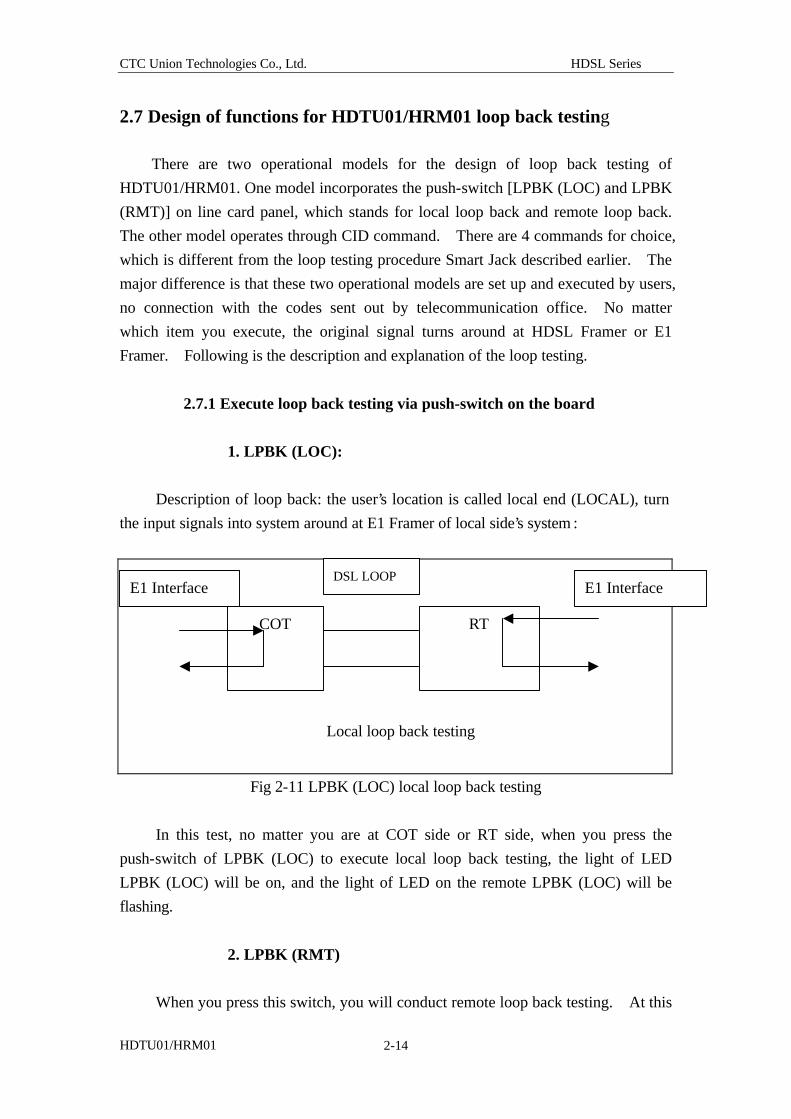
Description of loop back: the user’s location is called local end (LOCAL), turn
the input signals into system around at E1 Framer of local side’s system :
Fig 2-11 LPBK (LOC) local loop back testing
In this test, no matter you are at COT side or RT side, when you press the
push-switch of LPBK (LOC) to execute local loop back testing, the light of LED
LPBK (LOC) will be on, and the light of LED on the remote LPBK (LOC) will be
flashing.
2. LPBK (RMT)
When you press this switch, you will conduct remote loop back testing. At this
COT RT
DSL LOOP
Local loop back testing
E1 Interface E1 Interface
CTC Union Technologies Co., Ltd. HDSL Series
HDTU01/HRM01 2-15
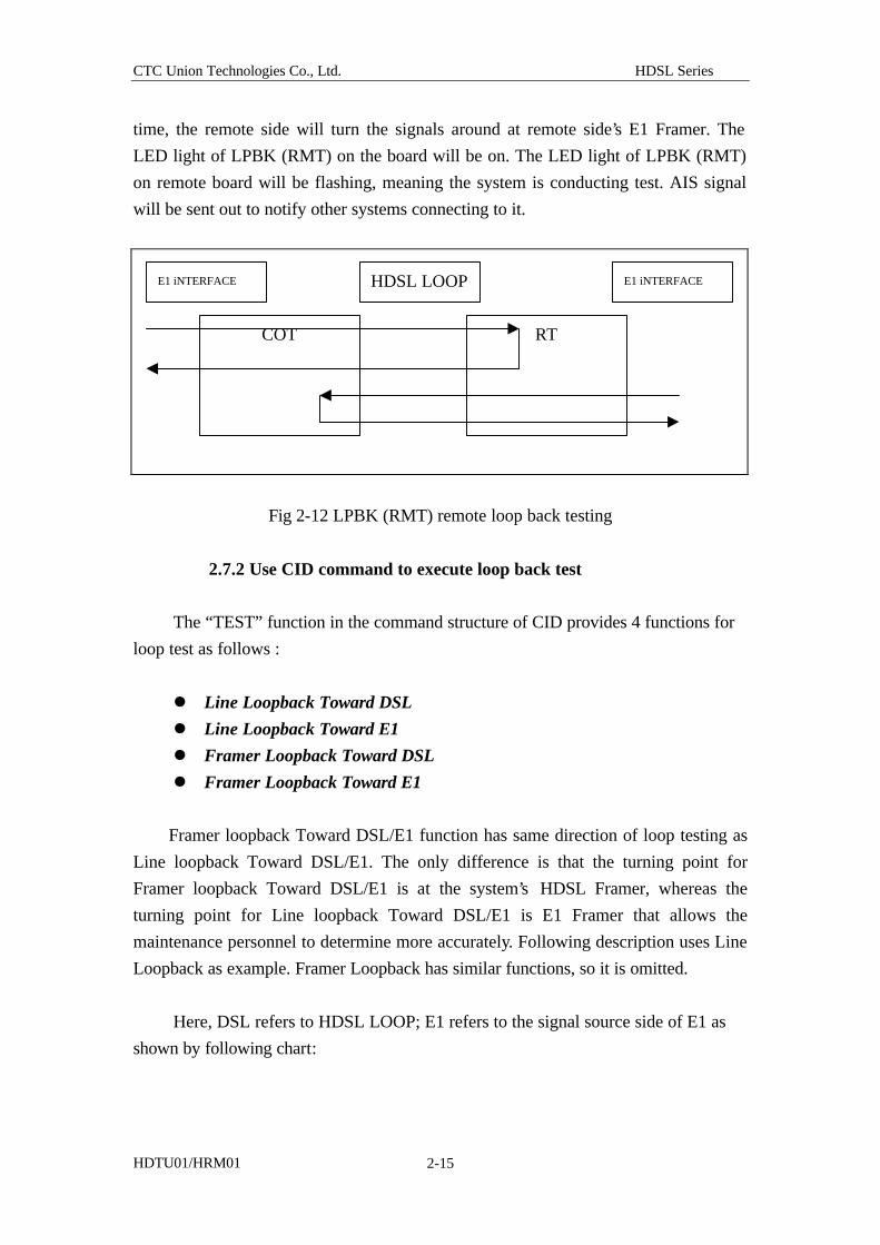
time, the remote side will turn the signals around at remote side’s E1 Framer. The
LED light of LPBK (RMT) on the board will be on. The LED light of LPBK (RMT)
on remote board will be flashing, meaning the system is conducting test. AIS signal
will be sent out to notify other systems connecting to it.
Fig 2-12 LPBK (RMT) remote loop back testing
2.7.2 Use CID command to execute loop back test
The “TEST” function in the command structure of CID provides 4 functions for
loop test as follows :
l Line Loopback Toward DSL
l Line Loopback Toward E1
l Framer Loopback Toward DSL
l Framer Loopback Toward E1
Framer loopback Toward DSL/E1 function has same direction of loop testing as
Line loopback Toward DSL/E1. The only difference is that the turning point for
Framer loopback Toward DSL/E1 is at the system’s HDSL Framer, whereas the
turning point for Line loopback Toward DSL/E1 is E1 Framer that allows the
maintenance personnel to determine more accurately. Following description uses Line
Loopback as example. Framer Loopback has similar functions, so it is omitted.
Here, DSL refers to HDSL LOOP; E1 refers to the signal source side of E1 as
shown by following chart:
COT RT
E1 iNTERFACE HDSL LOOP E1 iNTERFACE
CTC Union Technologies Co., Ltd. HDSL Series
HDTU01/HRM01 2-16
Fig 2-13 define the relevant locations of DSL and E1 in turning test
The paths for the two loop back testing are as follows:
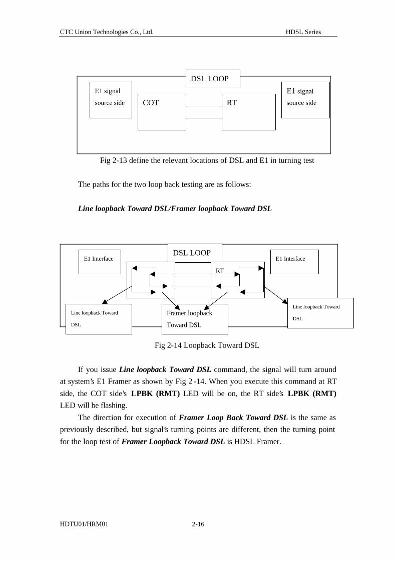
Line loopback Toward DSL/Framer loopback Toward DSL
Fig 2-14 Loopback Toward DSL
If you issue Line loopback Toward DSL command, the signal will turn around
at system’s E1 Framer as shown by Fig 2 -14. When you execute this command at RT
side, the COT side’s LPBK (RMT) LED will be on, the RT side’s LPBK (RMT)
LED will be flashing.
The direction for execution of Framer Loop Back Toward DSL is the same as
previously described, but signal’s turning points are different, then the turning point
for the loop test of Framer Loopback Toward DSL is HDSL Framer.
COT RT
E1 signal
source side
E1 signal
source side
DSL LOOP
DSL LOOP
RT
E1 Interface E1 Interface
Line loopback Toward
DSL Framer loopback
Toward DSL
Line loopback Toward
DSL
CTC Union Technologies Co., Ltd. HDSL Series
HDTU01/HRM01 2-17
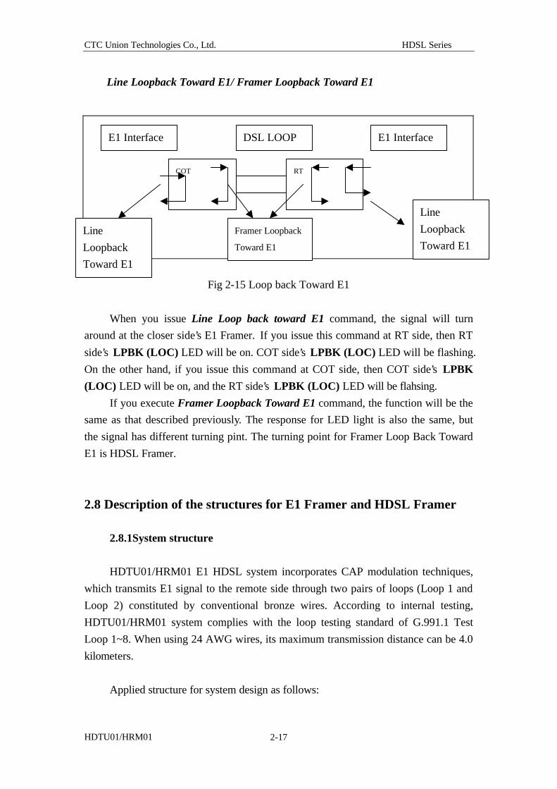
Line Loopback Toward E1/ Framer Loopback Toward E1
Fig 2-15 Loop back Toward E1
When you issue Line Loop back toward E1 command, the signal will turn
around at the closer side’s E1 Framer. If you issue this command at RT side, then RT
side’s LPBK (LOC) LED will be on. COT side’s LPBK (LOC) LED will be flashing.
On the other hand, if you issue this command at COT side, then COT side’s LPBK
(LOC) LED will be on, and the RT side’s LPBK (LOC) LED will be flahsing.
If you execute Framer Loopback Toward E1 command, the function will be the
same as that described previously. The response for LED light is also the same, but
the signal has different turning pint. The turning point for Framer Loop Back Toward
E1 is HDSL Framer.
2.8 Description of the structures for E1 Framer and HDSL Framer
2.8.1System structure
HDTU01/HRM01 E1 HDSL system incorporates CAP modulation techniques,
which transmits E1 signal to the remote side through two pairs of loops (Loop 1 and
Loop 2) constituted by conventional bronze wires. According to internal testing,
HDTU01/HRM01 system complies with the loop testing standard of G.991.1 Test
Loop 1~8. When using 24 AWG wires, its maximum transmission distance can be 4.0
kilometers.
Applied structure for system design as follows:
COT RT
E1 Interface E1 Interface DSL LOOP
Line
Loopback
Toward E1 Framer Loopback
Toward E1
Line
Loopback
Toward E1
CTC Union Technologies Co., Ltd. HDSL Series
HDTU01/HRM01 2-18
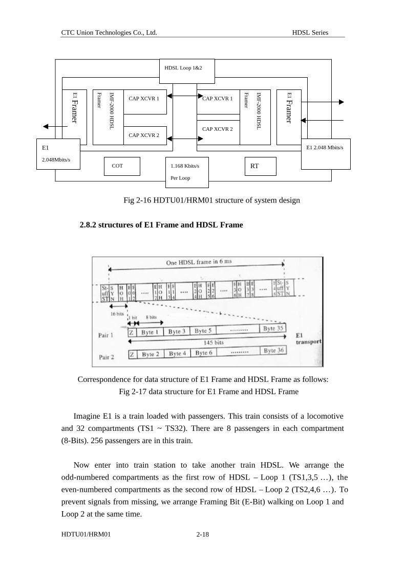
Fig 2-16 HDTU01/HRM01 structure of system design
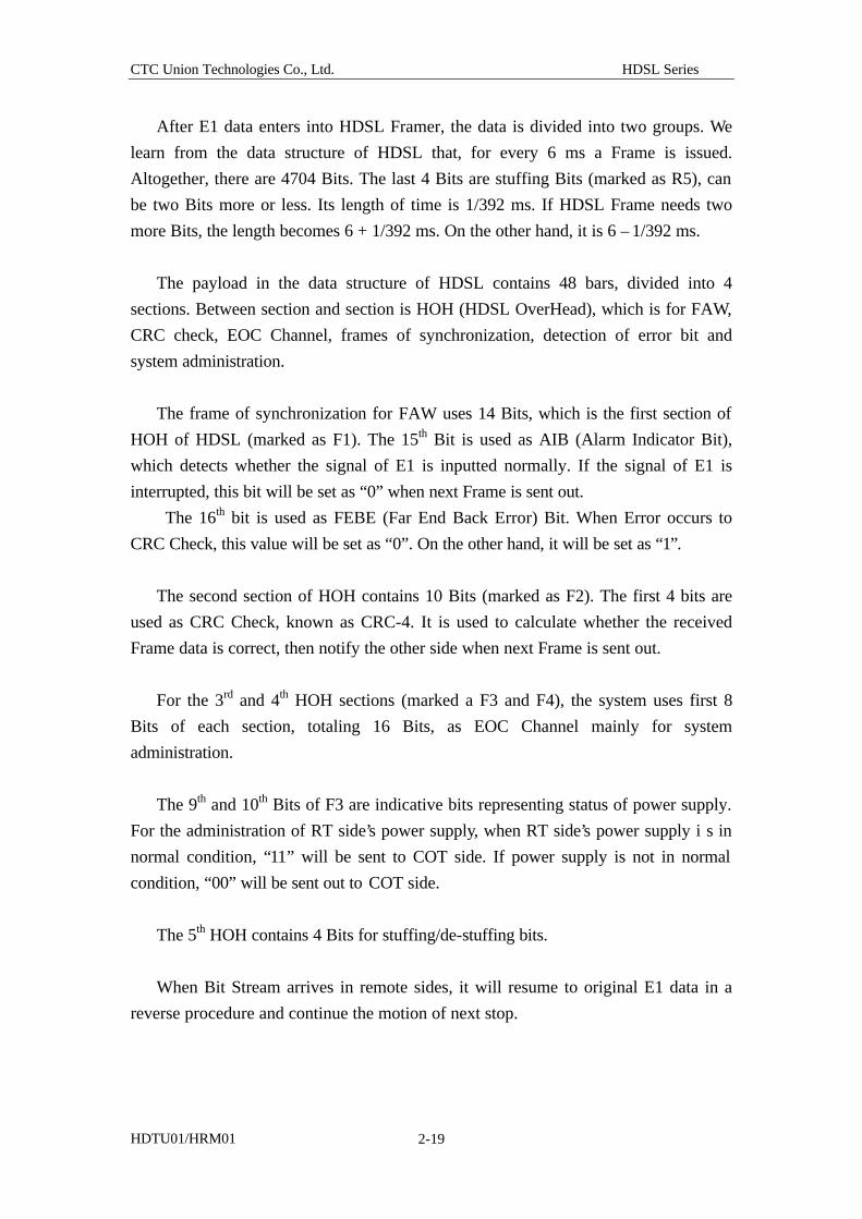
2.8.2 structures of E1 Frame and HDSL Frame
Correspondence for data structure of E1 Frame and HDSL Frame as follows:
Fig 2-17 data structure for E1 Frame and HDSL Frame
Imagine E1 is a train loaded with passengers. This train consists of a locomotive
and 32 compartments (TS1 ~ TS32). There are 8 passengers in each compartment
(8-Bits). 256 passengers are in this train.
Now enter into train station to take another train HDSL. We arrange the
odd-numbered compartments as the first row of HDSL – Loop 1 (TS1,3,5 …), the
even-numbered compartments as the second row of HDSL – Loop 2 (TS2,4,6 …). To
prevent signals from missing, we arrange Framing Bit (E-Bit) walking on Loop 1 and
Loop 2 at the same time.
CAP XCVR 1
CAP XCVR 2
E1 Fram
er
IMF-2000 H
DSL
Framer
COT
CAP XCVR 1
CAP XCVR 2
IMF-2000 H
DSL
Framer
E1 Fram
er
RT
HDSL Loop 1&2
E1 2.048 Mbits/s E1
2.048Mbits/s 1.168 Kbits/s
Per Loop
CTC Union Technologies Co., Ltd. HDSL Series
HDTU01/HRM01 2-19
After E1 data enters into HDSL Framer, the data is divided into two groups. We
learn from the data structure of HDSL that, for every 6 ms a Frame is issued.
Altogether, there are 4704 Bits. The last 4 Bits are stuffing Bits (marked as R5), can
be two Bits more or less. Its length of time is 1/392 ms. If HDSL Frame needs two
more Bits, the length becomes 6 + 1/392 ms. On the other hand, it is 6 – 1/392 ms.
The payload in the data structure of HDSL contains 48 bars, divided into 4
sections. Between section and section is HOH (HDSL OverHead), which is for FAW,
CRC check, EOC Channel, frames of synchronization, detection of error bit and
system administration.
The frame of synchronization for FAW uses 14 Bits, which is the first section of
HOH of HDSL (marked as F1). The 15th Bit is used as AIB (Alarm Indicator Bit),
which detects whether the signal of E1 is inputted normally. If the signal of E1 is
interrupted, this bit will be set as “0” when next Frame is sent out.
The 16th bit is used as FEBE (Far End Back Error) Bit. When Error occurs to
CRC Check, this value will be set as “0”. On the other hand, it will be set as “1”.
The second section of HOH contains 10 Bits (marked as F2). The first 4 bits are
used as CRC Check, known as CRC-4. It is used to calculate whether the received
Frame data is correct, then notify the other side when next Frame is sent out.
For the 3rd and 4th HOH sections (marked a F3 and F4), the system uses first 8
Bits of each section, totaling 16 Bits, as EOC Channel mainly for system
administration.
The 9th and 10th Bits of F3 are indicative bits representing status of power supply.
For the administration of RT side’s power supply, when RT side’s power supply i s in
normal condition, “11” will be sent to COT side. If power supply is not in normal
condition, “00” will be sent out to COT side.
The 5th HOH contains 4 Bits for stuffing/de-stuffing bits.
When Bit Stream arrives in remote sides, it will resume to original E1 data in a
reverse procedure and continue the motion of next stop.
CTC Union Technologies Co., Ltd. HDSL Series
HDTU01/HRM01 2-20
2.8.3 Use of CRC check code
The CRC check code used by HDTU01/HRM01 system contains 4 Bits and
incorporates a 23-ordered polynomial to calculate whether the received data is correct.
This functions is included in IMF-2000 HDSL Framer. The result of check is written
in temporary storage and is read by administrative program.
2.8.4 EOC Channel
HDTU01/HRM01 incorporates EOC Channel to administer system. 13 Bits are
included in this channel:
Bit 1, 2 Address Bits: 11 for HTU-C, 00 for HTU-R
Bit 3 Data or OP code
Bit 4 Odd Byte/Even Byte
Bit 5 Unused set value “1”
Bit 6~13 Define Message
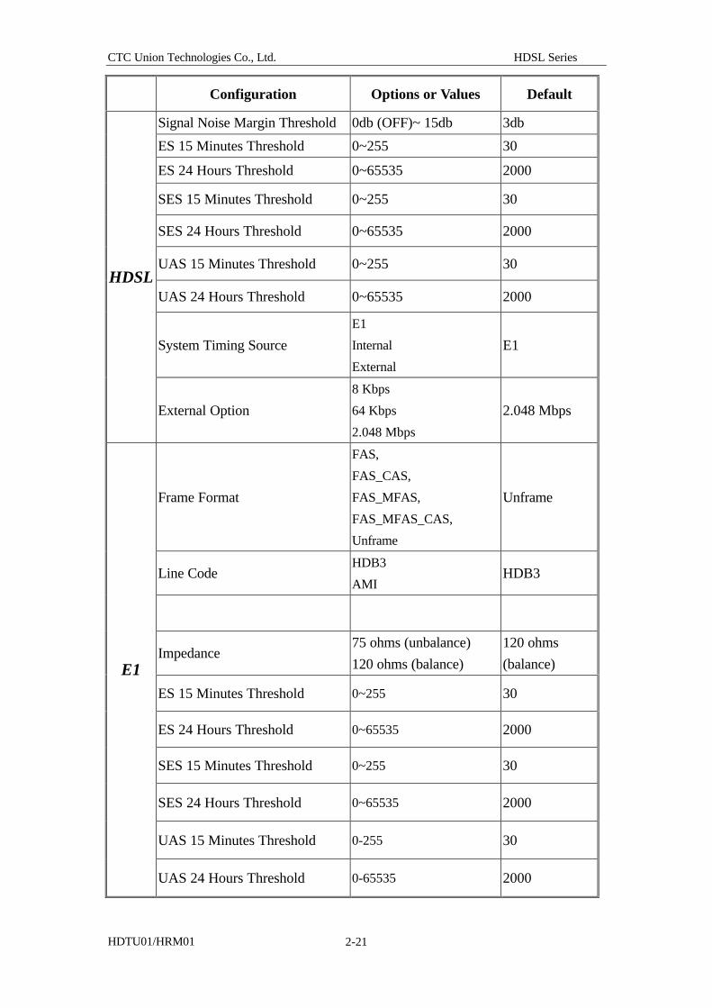
2.9 Default parameters for HDTU01/HRM01 system
When HDTU01/HRM01 is shipped, a group of parameters is set for this system.
Users may adjust the default values as they wish to do so.
Following table contains the adjusted value for parameters and default value
prior to shipment.
CTC Union Technologies Co., Ltd. HDSL Series
HDTU01/HRM01 2-21
Configuration Options or Values Default
Signal Noise Margin Threshold 0db (OFF)~ 15db 3db
ES 15 Minutes Threshold 0~255 30
ES 24 Hours Threshold 0~65535 2000
SES 15 Minutes Threshold 0~255 30
SES 24 Hours Threshold 0~65535 2000
UAS 15 Minutes Threshold 0~255 30
UAS 24 Hours Threshold 0~65535 2000
System Timing Source
E1
Internal
External
E1
HDSL
External Option
8 Kbps
64 Kbps
2.048 Mbps
2.048 Mbps
Frame Format
FAS,
FAS_CAS,
FAS_MFAS,
FAS_MFAS_CAS,
Unframe
Unframe
Line Code HDB3
AMI HDB3
Impedance 75 ohms (unbalance)
120 ohms (balance)
120 ohms
(balance)
ES 15 Minutes Threshold 0~255 30
ES 24 Hours Threshold 0~65535 2000
SES 15 Minutes Threshold 0~255 30
SES 24 Hours Threshold 0~65535 2000
UAS 15 Minutes Threshold 0-255 30
E1
UAS 24 Hours Threshold 0-65535 2000
CTC Union Technologies Co., Ltd. HDSL Series
HDTU01/HRM01 2-22
Configuration Options and Values Default
DSL Mode COT
RT COT
Test Time Out Enable
Disable Enable
Test Duration 0 ~ 127 10
Smart Jack enable Enable
Disable Enable
Date yyyy / mm / dd 1999/8/01
SYSTEM
Time hh : mm : ss 08:00:00
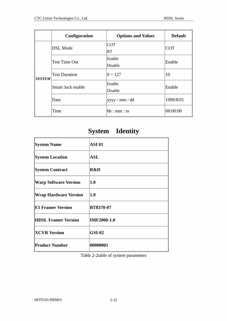
System Identity
System Name ASI 01
System Location ASI.
System Contract R&D
Warp Software Version 1.0
Wrap Hardware Version 1.0
E1 Framer Version BT8370-07
HDSL Framer Version IMF2000-1.0
XCVR Version GSI-02
Product Number 00000001
Table 2-2table of system parameters
CTC Union Technologies Co., Ltd. HDSL Series
HDTU01/HRM01 3-1
Chapter 3. System installation and setup of configuration
When you receive your HDTU01/HRM01 system, you need to connect the
wires first. On the backboard of HDTU01/HRM01 you can find the names for all
interfaces. You have to hook up the system correctly, then the system can start
working normally.
3.1 Check before connecting HDTU01/HRM01
Now you are opening the package of the machine. Depending on the type of
machines you purchase, there is some difference between the interfaces of line card of
19” E1 HDSL and that of stand alone model. We have discussed these two models in
chapter 2. Please read carefully before connection.
Before you proceed to installing HDTU01/HRM01, please check all items listed
in following table to make sure that all circuits or cables are correct. Pay attention to
power source and grounding especially in order to prevent the line card from being hit
by leaking electricity.
Item Check List Yes No
1 Check whether HDSL Loop has Loading Coil ? Loading Coin has
too be removed.
2 Check whether the cable is twisted wire or star-twisted wire. If it is
star-twisted wire, be careful when you install. Do not use 4 pith of
same bunch as HDSL Loop wire. The wires for two Loops have to
be of different bunches.
3 Be sure to use single-pith bronze wire. Do not use twisted wire.
4 Make one end of HDSL loop short-circuited. Measure Ohm value
on the other end by a multimeter. The value has to be less than or
equal to 900 Ohms. When exceeding this value, there is no
guarantee that both ends can communicate.
5. Check Frame Ground. In the process of installation, be cautious of
the connection of frame ground so as to prevent static or leading
electricity from hitting.
Connect the frame ground provided by the system to the joint
CTC Union Technologies Co., Ltd. HDSL Series
HDTU01/HRM01 3-2
connecting point of machine room.
Attention please. If the grounding line is not connected, and the
Line of AC power supply connects by mistake, the system may
be damaged.
Table 3-1 preparation before installation
3.2 setup of configuration
After circuits are connected, you can proceed to setup of system program. This
step deals with setup of various communication configurations for HDTU01/HRM01.
Just like communication between human being, COT side of HDTU01/HRM01 and
RT side have to understand the signals sent out from each other. Therefore, the
procedures for setup of configuration are very detailed. Naturally, the company
provides a set of default prior to shipment of product in order to meet most of user’s
needs with the least setup.
Prior to setting up, check whether the software and hardware are complete:
l One personal computer. RS-232 communication interface is the only
requirement for hardware.
l The software has to have compatible VT-100 terminal program. You can
use the “terminal” program included in Windows 95. This program is
located under “program/affiliated applied program”.
*Remarks: if you use standard VT 100 terminal program, connect it to CID
interface to make sure that CID program is executing correctly. If you use the
terminal program included in Chinese Windows 95/98, use the number keys to
control the direction of cursor’s movement. Press the Num Lock on the right
keyboard, then use 8,6,4,2 to move the cursor.
l Set up the parameters of terminal program as follows
Set up the transmission speed of RS-232 as 9.6 kbps
Set up the length of bit as 8
Set up Parity as None; Set up Stop Bit as 1
l Use RS-232 Cable included in HDTU01/HRM01 to connect CID interface
of HDTU01/HRM01 to the RS-232 interface of personal computer.
After the preparation, proceed to setup of system configuration.
CTC Union Technologies Co., Ltd. HDSL Series
HDTU01/HRM01 3-3
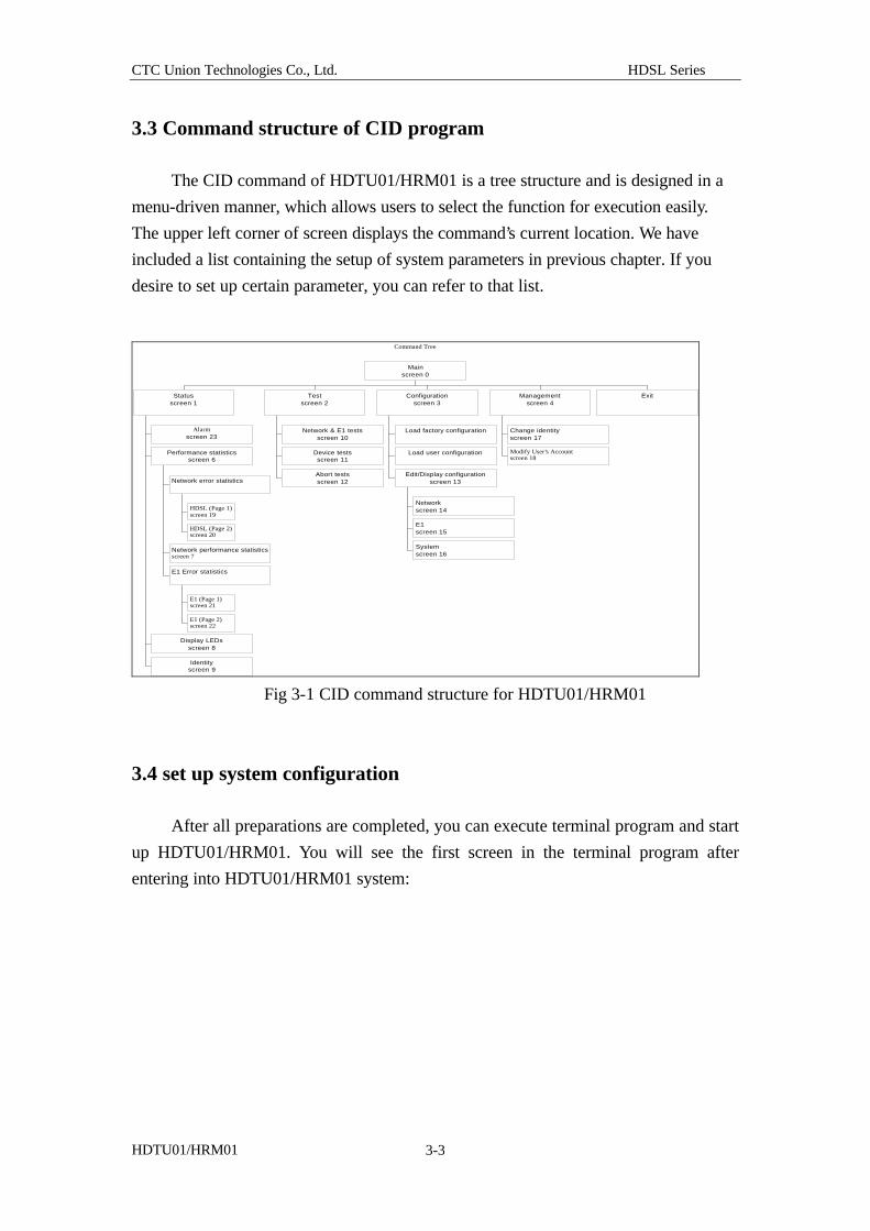
3.3 Command structure of CID program
The CID command of HDTU01/HRM01 is a tree structure and is designed in a
menu-driven manner, which allows users to select the function for execution easily.
The upper left corner of screen displays the command’s current location. We have
included a list containing the setup of system parameters in previous chapter. If you
desire to set up certain parameter, you can refer to that list.
Fig 3-1 CID command structure for HDTU01/HRM01
3.4 set up system configuration
After all preparations are completed, you can execute terminal program and start
up HDTU01/HRM01. You will see the first screen in the terminal program after
entering into HDTU01/HRM01 system:
Command Tree
Alarmscreen 23
HDSL (Page 1)screen 19
HDSL (Page 2)screen 20
Network error statistics
Network performance statisticsscreen 7
E1 (Page 1)screen 21
E1 (Page 2)screen 22
E1 Error statistics
Performance statisticsscreen 6
Display LEDsscreen 8
Identityscreen 9
Statusscreen 1
Network & E1 testsscreen 10
Device testsscreen 11
Abort testsscreen 12
Testscreen 2
Load factory configuration
Load user configuration
Networkscreen 14
E1screen 15
Systemscreen 16
Edit/Display configurationscreen 13
Configurationscreen 3
Change identityscreen 17
Modify User's Accountscreen 18
Managementscreen 4
Exit
Mainscreen 0
CTC Union Technologies Co., Ltd. HDSL Series
HDTU01/HRM01 3-4
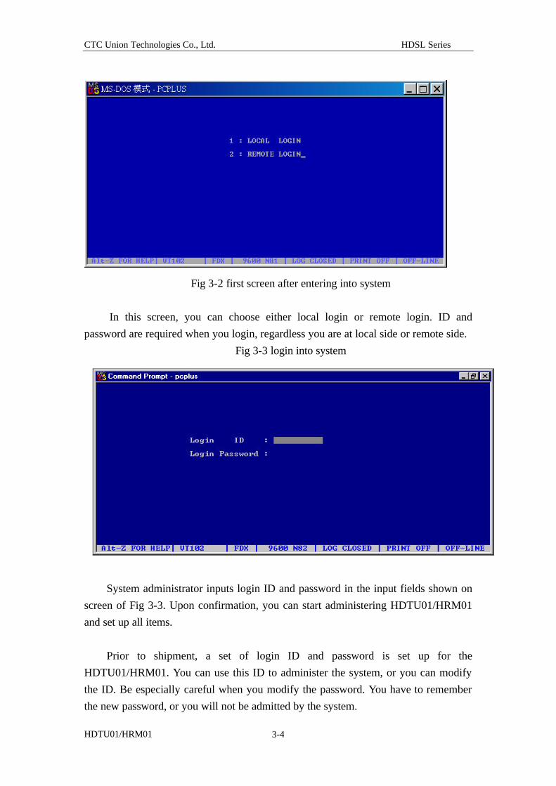
Fig 3-2 first screen after entering into system
In this screen, you can choose either local login or remote login. ID and
password are required when you login, regardless you are at local side or remote side.
Fig 3-3 login into system
System administrator inputs login ID and password in the input fields shown on
screen of Fig 3-3. Upon confirmation, you can start administering HDTU01/HRM01
and set up all items.
Prior to shipment, a set of login ID and password is set up for the
HDTU01/HRM01. You can use this ID to administer the system, or you can modify
the ID. Be especially careful when you modify the password. You have to remember
the new password, or you will not be admitted by the system.
CTC Union Technologies Co., Ltd. HDSL Series
HDTU01/HRM01 3-5
The system of HDTU01/HRM01 allows remote login. The system allows one
user to enter each time. if there is a user in the local side, login will not be allowed for
remote side.
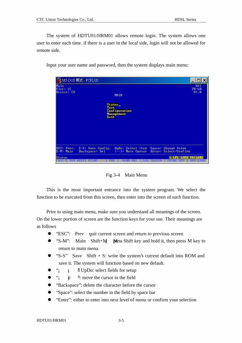
Input your user name and password, then the system displays main menu:
Fig 3-4 Main Menu
This is the most important entrance into the system program. We select the
function to be executed from this screen, then enter into the screen of such function.
Prior to using main menu, make sure you understand all meanings of the screen.
On the lower portion of screen are the function keys for your use. Their meanings are
as follows
l “ESC”: Prev quit current screen and return to previous screen
l “S-M”: Main Shift+M¡ Mpress Shift key and hold it, then press M key to
return to main menu.
l “S-S” Save Shift + S: write the system’s current default into ROM and
save it. The system will function based on new default.
l “¡ õ¡ ô” UpDn: select fields for setup
l “¡ ö¡ ÷”: move the cursor in the field
l “Backspace”: delete the character before the cursor
l “Space”: select the number in the field by space bar
l “Enter”: either to enter into next level of menu or confirm your selection
CTC Union Technologies Co., Ltd. HDSL Series
HDTU01/HRM01 3-6
Let’s take a look at the lower left corner. Some indicative messages appear here
to indicate the actions up to be executed now. The lower right corner displays
warning or error message. When system detects problems, this corner will display
relevant message for reference of maintenance.
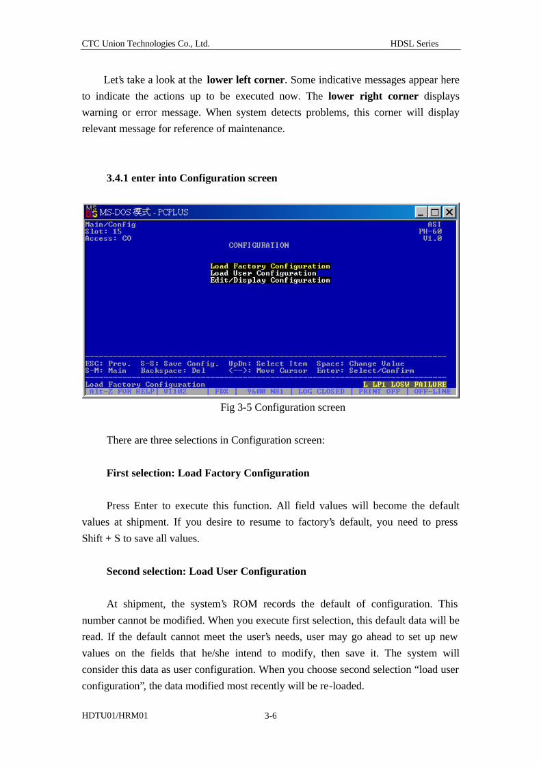
3.4.1 enter into Configuration screen
Fig 3-5 Configuration screen
There are three selections in Configuration screen:
First selection: Load Factory Configuration
Press Enter to execute this function. All field values will become the default
values at shipment. If you desire to resume to factory’s default, you need to press
Shift + S to save all values.
Second selection: Load User Configuration
At shipment, the system’s ROM records the default of configuration. This
number cannot be modified. When you execute first selection, this default data will be
read. If the default cannot meet the user’s needs, user may go ahead to set up new
values on the fields that he/she intend to modify, then save it. The system will
consider this data as user configuration. When you choose second selection “load user
configuration”, the data modified most recently will be re-loaded.
CTC Union Technologies Co., Ltd. HDSL Series
HDTU01/HRM01 3-7
Selections 1 and 2 allow you to restore the factory default or the original setup
permitting normal operation, if abnormal modification occurs when you set up the
system.
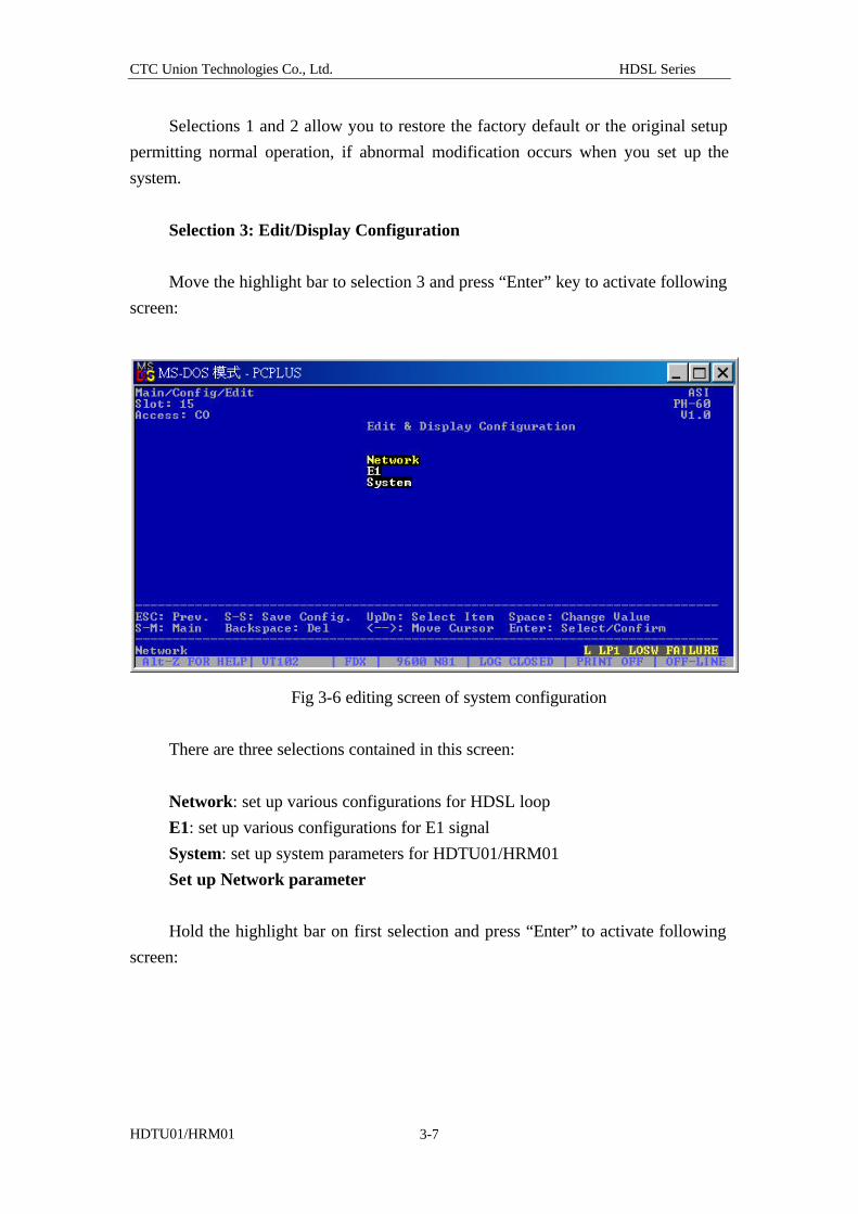
Selection 3: Edit/Display Configuration
Move the highlight bar to selection 3 and press “Enter” key to activate following
screen:
Fig 3-6 editing screen of system configuration
There are three selections contained in this screen:
Network: set up various configurations for HDSL loop
E1: set up various configurations for E1 signal
System: set up system parameters for HDTU01/HRM01
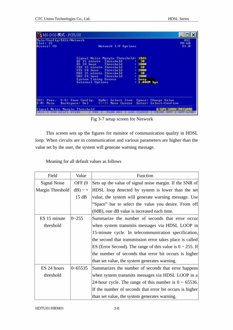
Set up Network parameter
Hold the highlight bar on first selection and press “Enter” to activate following
screen:
CTC Union Technologies Co., Ltd. HDSL Series
HDTU01/HRM01 3-8
Fig 3-7 setup screen for Network
This screen sets up the figures for monitor of communication quality in HDSL
loop. When circuits are in communication and various parameters are higher than the
value set by the user, the system will generate warning message.
Meaning for all default values as follows
Field Value Function
Signal Noise
Margin Threshold
OFF (0
dB) ~ +
15 dB
Sets up the value of signal noise margin. If the SNR of
HDSL loop detected by system is lower than the set
value, the system will generate warning message. Use
“Space” bar to select the value you desire. From off
(0dB), one dB value is increased each time.
ES 15 minute
threshold
0~255
Summarize the number of seconds that error occur
when system transmits messages via HDSL LOOP in
15-minute cycle. In telecommunication specification,
the second that transmission error takes place is called
ES (Error Second). The range of this value is 0 ~ 255. If
the number of seconds that error bit occurs is higher
than set value, the system generates warning.
ES 24 hours
threshold
0~65535
Summarizes the number of seconds that error happens
when system transmits messages via HDSL LOOP in a
24-hour cycle. The range of this number is 0 ~ 65536.
If the number of seconds that error bit occurs is higher
than set value, the system generates warning.
CTC Union Technologies Co., Ltd. HDSL Series
HDTU01/HRM01 3-9
SES 15 minute
threshold
0~255 Summarizes the number of seconds that severe error
occurs when system transmits signals via HDSL LOOP
in 15-minute cycle. In the communication specification,
if the error bit rate is higher than 10 –3, this second is
called SES (Severely Error Second). The range for this
value is 0 ~ 255. If the number of seconds that error bit
occurs is higher than set value, the system generates
warning.
SES 24 hours
threshold
0 ~ 65535 Summarizes the number of seconds that severe error
happens when system transmits messages via HDSL
LOOP in a 24-hour cycle. The range of this number is 0
~ 65536. If the number of seconds that error bit occurs
is higher than the set value, the system generates
warning.
UAS 15 minutes
threshold
0~255 Un-Available Second records the number of invalid
communication seconds in 15-minute cycle. UAS refers
to the period from the time that 10 SES happens
consecutively to the time that 10 non-SES occurs
consecutively.
UAS 24 hours
threshold
0~65535
Records the number of Un-Available Second in 24-hour
cycle.
System Timing
Source
E1
Internal
External
Clock frequency for reference of COT and RT. Its
source can be any one listed on the left. The default is
“E1”, meaning that the system’s clock frequency refers
to the input E1 signal. Such signal generates
synchronization clock signal. “Internal” refers to the
synchronization clock signal generated in reference to
HDSL LOOP. External refers to the synchronization
clock signal generated by using system’s external signal
source.
External Options 8k bps
64k bps
2.048
Mbps
Uses external clock. HDTU01/HRM01 provides
external clock input interface and chooses 3 frequency
input value.
Table 3-2 Network various parameters
CTC Union Technologies Co., Ltd. HDSL Series
HDTU01/HRM01 3-10
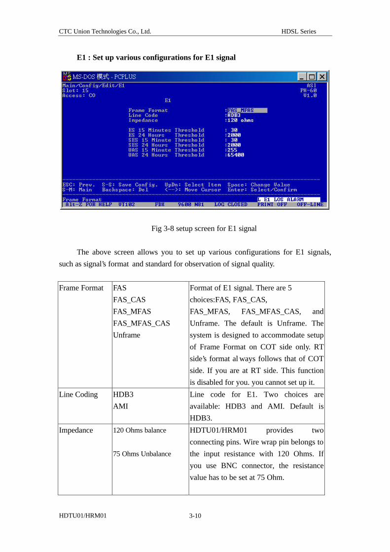
E1 : Set up various configurations for E1 signal
Fig 3-8 setup screen for E1 signal
The above screen allows you to set up various configurations for E1 signals,
such as signal’s format and standard for observation of signal quality.
Frame Format FAS
FAS_CAS
FAS_MFAS
FAS_MFAS_CAS
Unframe
Format of E1 signal. There are 5
choices:FAS, FAS_CAS,
FAS_MFAS, FAS_MFAS_CAS, and
Unframe. The default is Unframe. The
system is designed to accommodate setup
of Frame Format on COT side only. RT
side’s format al ways follows that of COT
side. If you are at RT side. This function
is disabled for you. you cannot set up it.
Line Coding HDB3
AMI
Line code for E1. Two choices are
available: HDB3 and AMI. Default is
HDB3.
Impedance 120 Ohms balance
75 Ohms Unbalance
HDTU01/HRM01 provides two
connecting pins. Wire wrap pin belongs to
the input resistance with 120 Ohms. If
you use BNC connector, the resistance
value has to be set at 75 Ohm.
CTC Union Technologies Co., Ltd. HDSL Series
HDTU01/HRM01 3-11
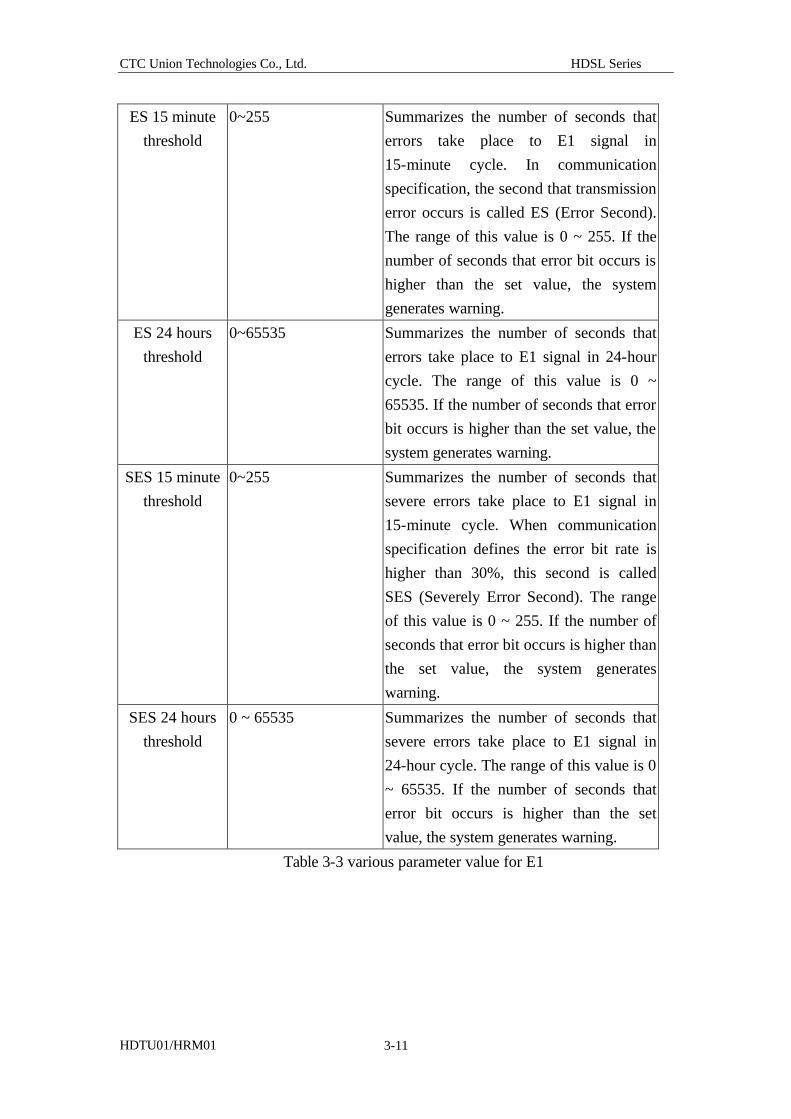
ES 15 minute
threshold
0~255
Summarizes the number of seconds that
errors take place to E1 signal in
15-minute cycle. In communication
specification, the second that transmission
error occurs is called ES (Error Second).
The range of this value is 0 ~ 255. If the
number of seconds that error bit occurs is
higher than the set value, the system
generates warning.
ES 24 hours
threshold
0~65535
Summarizes the number of seconds that
errors take place to E1 signal in 24-hour
cycle. The range of this value is 0 ~
65535. If the number of seconds that error
bit occurs is higher than the set value, the
system generates warning.
SES 15 minute
threshold
0~255 Summarizes the number of seconds that
severe errors take place to E1 signal in
15-minute cycle. When communication
specification defines the error bit rate is
higher than 30%, this second is called
SES (Severely Error Second). The range
of this value is 0 ~ 255. If the number of
seconds that error bit occurs is higher than
the set value, the system generates
warning.
SES 24 hours
threshold
0 ~ 65535 Summarizes the number of seconds that
severe errors take place to E1 signal in
24-hour cycle. The range of this value is 0
~ 65535. If the number of seconds that
error bit occurs is higher than the set
value, the system generates warning.
Table 3-3 various parameter value for E1
CTC Union Technologies Co., Ltd. HDSL Series
HDTU01/HRM01 3-12
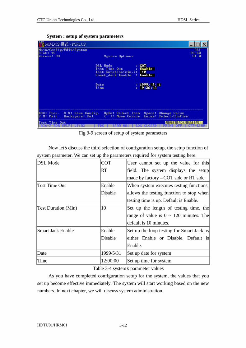
System : setup of system parameters
Fig 3-9 screen of setup of system parameters
Now let’s discuss the third selection of configuration setup, the setup function of
system parameter. We can set up the parameters required for system testing here.
DSL Mode COT
RT
User cannot set up the value for this
field. The system displays the setup
made by factory – COT side or RT side.
Test Time Out Enable
Disable
When system executes testing functions,
allows the testing function to stop when
testing time is up. Default is Enable.
Test Duration (Min) 10 Set up the length of testing time. the
range of value is 0 ~ 120 minutes. The
default is 10 minutes.
Smart Jack Enable Enable
Disable
Set up the loop testing for Smart Jack as
either Enable or Disable. Default is
Enable.
Date 1999/5/31 Set up date for system
Time 12:00:00 Set up time for system
Table 3-4 system’s parameter values
As you have completed configuration setup for the system, the values that you
set up become effective immediately. The system will start working based on the new
numbers. In next chapter, we will discuss system administration.
CTC Union Technologies Co., Ltd. HDSL Series
HDTU01/HRM01 4-1
Chapter 4 System administration (Management)
This chapter provides the identification data of HDTU01/HRM01 system to
system administrator and users. Prior to shipment, this system will provide a user’s ID
and password to user. User may modify ID and password by the functions described
in this chapter.
On the main menu, choose “Management” to enter into the screen of managerial
functions.
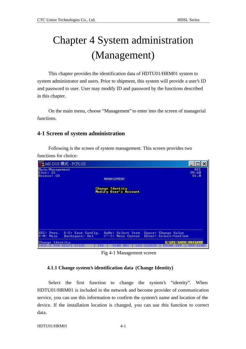
4-1 Screen of system administration
Following is the screen of system management. This screen provides two
functions for choice:
Fig 4-1 Management screen
4.1.1 Change system’s identification data (Change Identity)
Select the first function to change the system’s “identity”. When
HDTU01/HRM01 is included in the network and become provider of communication
service, you can use this information to confirm the system’s name and location of the
device. If the installation location is changed, you can use this function to correct
data.
CTC Union Technologies Co., Ltd. HDSL Series
HDTU01/HRM01 4-2
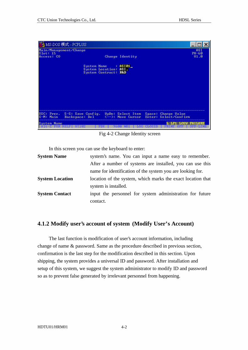
Fig 4-2 Change Identity screen
In this screen you can use the keyboard to enter:
System Name system’s name. You can input a name easy to remember.
After a number of systems are installed, you can use this
name for identification of the system you are looking for.
System Location location of the system, which marks the exact location that
system is installed.
System Contact input the personnel for system administration for future
contact.
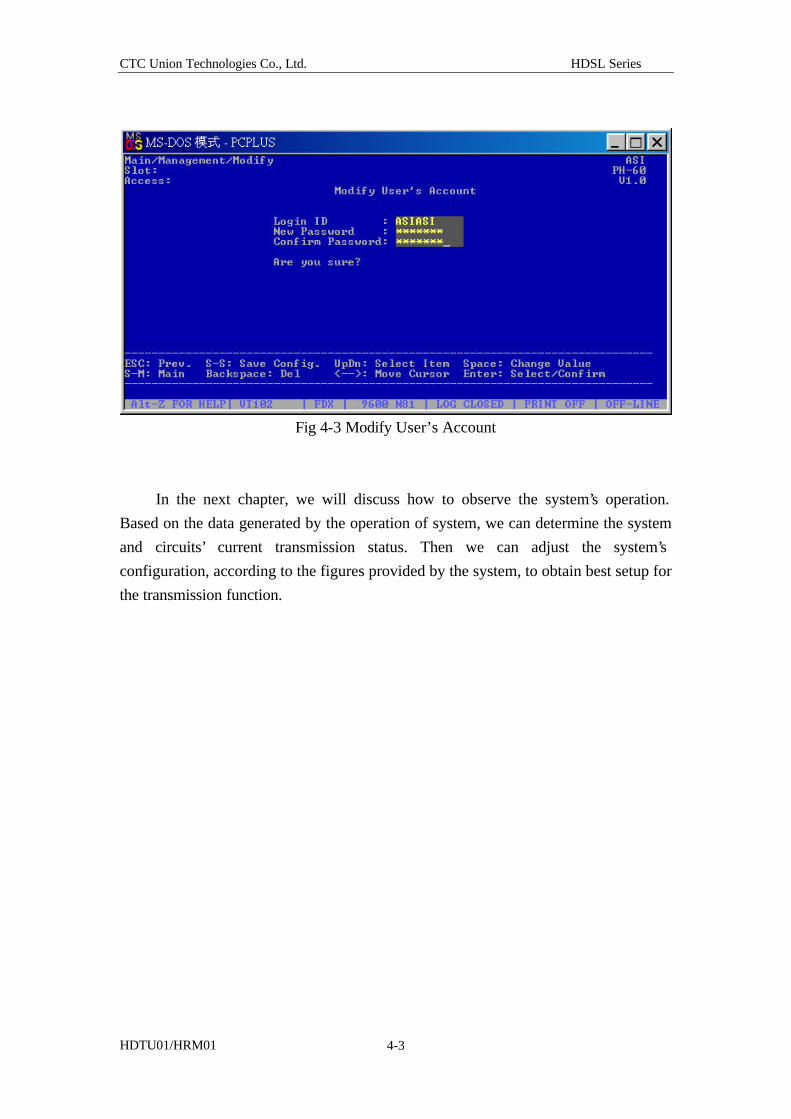
4.1.2 Modify user’s account of system (Modify User’s Account) The last function is modification of user’s account information, including
change of name & password. Same as the procedure described in previous section,
confirmation is the last step for the modification described in this section. Upon
shipping, the system provides a universal ID and password. After installation and
setup of this system, we suggest the system administrator to modify ID and password
so as to prevent false generated by irrelevant personnel from happening.
CTC Union Technologies Co., Ltd. HDSL Series
HDTU01/HRM01 4-3
Fig 4-3 Modify User’s Account
In the next chapter, we will discuss how to observe the system’s operation.
Based on the data generated by the operation of system, we can determine the system
and circuits’ current transmission status. Then we can adjust the system’s
configuration, according to the figures provided by the system, to obtain best setup for
the transmission function.
CTC Union Technologies Co., Ltd. HDSL Series
HDTU01/HRM01 5-1
Chapter 5 System alarm and performance statistics
In the previous chapters, we described how to set up and administer
HDTU01/HRM01 system. Generally, these operations are mandatory procedure after
first installation of HDTU01/HRM01. Now we are going to introduce how to observe
the system’s operation.
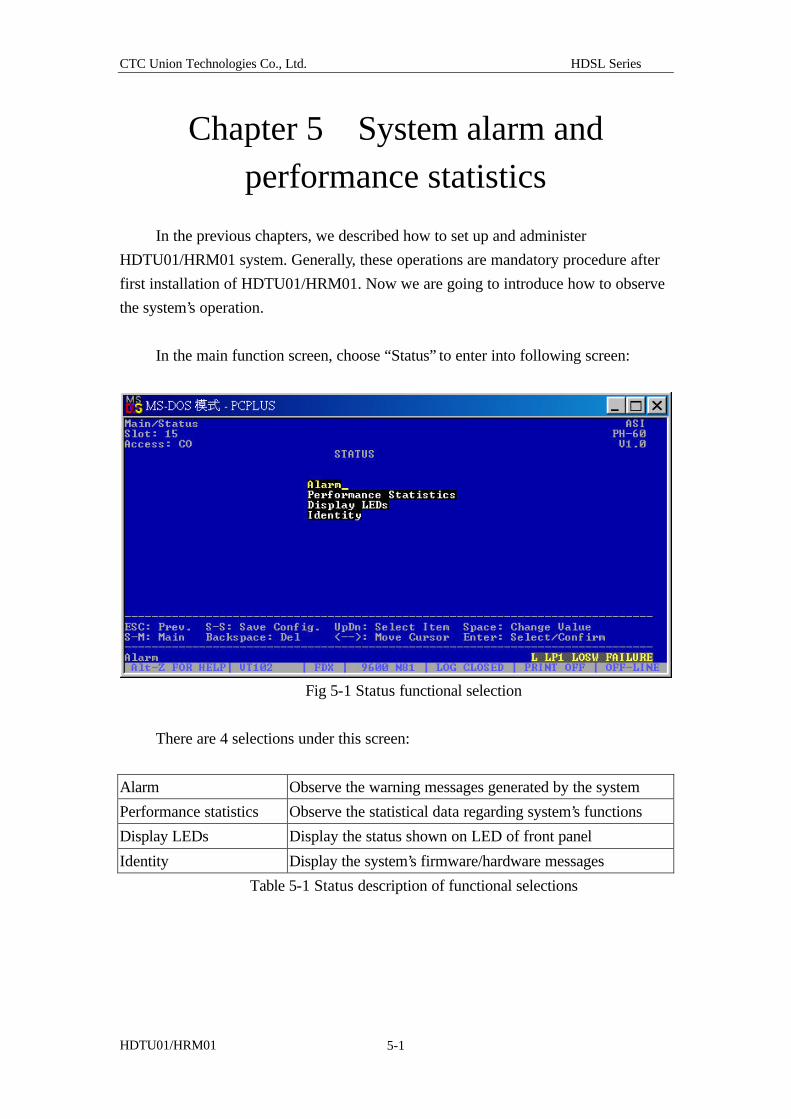
In the main function screen, choose “Status” to enter into following screen:
Fig 5-1 Status functional selection
There are 4 selections under this screen:
Alarm Observe the warning messages generated by the system
Performance statistics Observe the statistical data regarding system’s functions
Display LEDs Display the status shown on LED of front panel
Identity Display the system’s firmware/hardware messages
Table 5-1 Status description of functional selections
CTC Union Technologies Co., Ltd. HDSL Series
HDTU01/HRM01 5-2
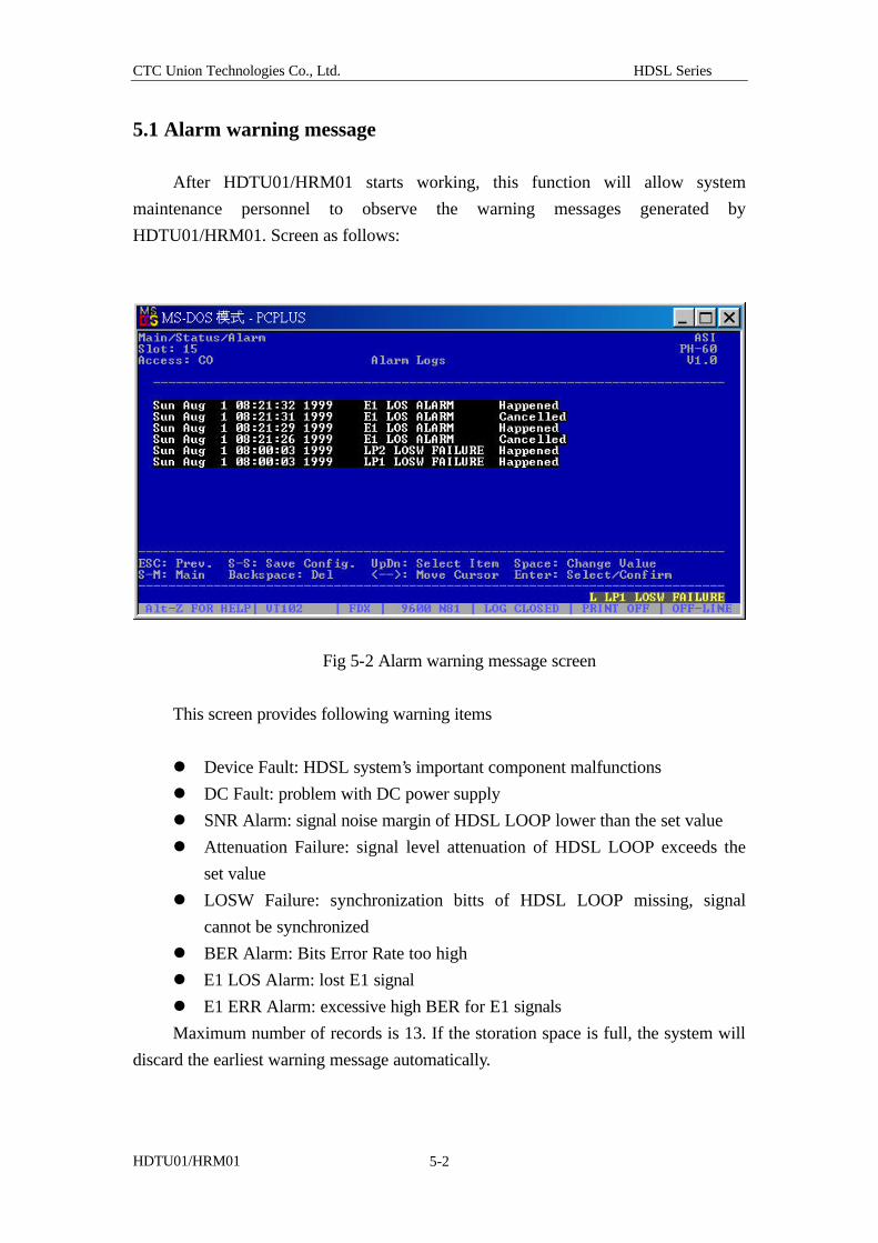
5.1 Alarm warning message After HDTU01/HRM01 starts working, this function will allow system
maintenance personnel to observe the warning messages generated by
HDTU01/HRM01. Screen as follows:
Fig 5-2 Alarm warning message screen
This screen provides following warning items
l Device Fault: HDSL system’s important component malfunctions
l DC Fault: problem with DC power supply
l SNR Alarm: signal noise margin of HDSL LOOP lower than the set value
l Attenuation Failure: signal level attenuation of HDSL LOOP exceeds the
set value
l LOSW Failure: synchronization bitts of HDSL LOOP missing, signal
cannot be synchronized
l BER Alarm: Bits Error Rate too high
l E1 LOS Alarm: lost E1 signal
l E1 ERR Alarm: excessive high BER for E1 signals
Maximum number of records is 13. If the storation space is full, the system will
discard the earliest warning message automatically.
CTC Union Technologies Co., Ltd. HDSL Series
HDTU01/HRM01 5-3
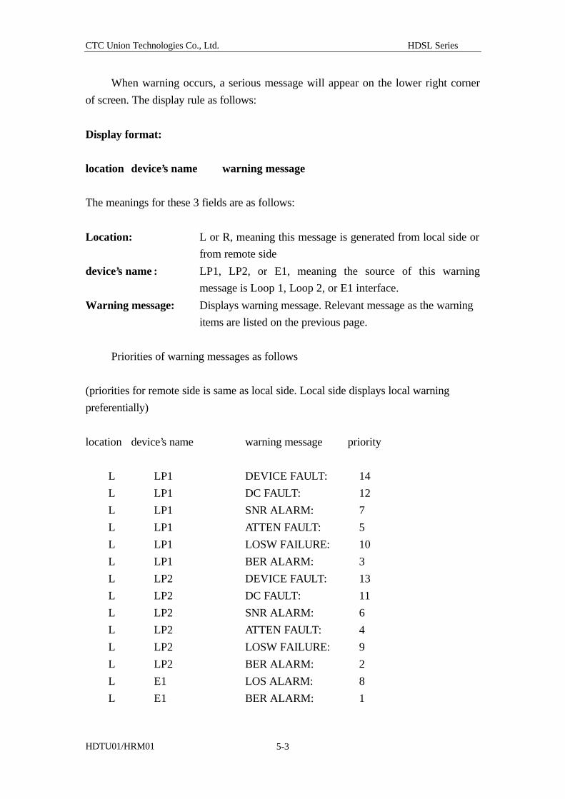
When warning occurs, a serious message will appear on the lower right corner
of screen. The display rule as follows:
Display format:
location device’s name warning message
The meanings for these 3 fields are as follows:
Location: L or R, meaning this message is generated from local side or
from remote side
device’s name : LP1, LP2, or E1, meaning the source of this warning
message is Loop 1, Loop 2, or E1 interface.
Warning message: Displays warning message. Relevant message as the warning
items are listed on the previous page.
Priorities of warning messages as follows
(priorities for remote side is same as local side. Local side displays local warning
preferentially)
location device’s name warning message priority
L LP1 DEVICE FAULT: 14
L LP1 DC FAULT: 12
L LP1 SNR ALARM: 7
L LP1 ATTEN FAULT: 5
L LP1 LOSW FAILURE: 10
L LP1 BER ALARM: 3
L LP2 DEVICE FAULT: 13
L LP2 DC FAULT: 11
L LP2 SNR ALARM: 6
L LP2 ATTEN FAULT: 4
L LP2 LOSW FAILURE: 9
L LP2 BER ALARM: 2
L E1 LOS ALARM: 8
L E1 BER ALARM: 1
CTC Union Technologies Co., Ltd. HDSL Series
HDTU01/HRM01 5-4
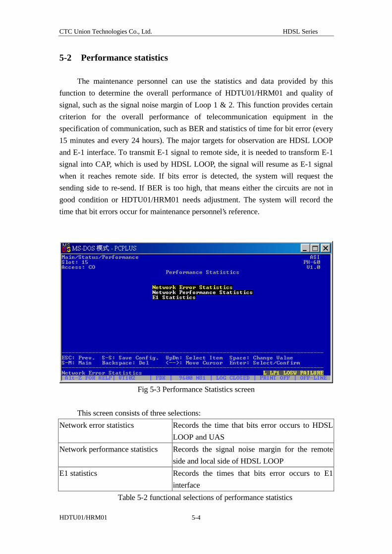
5-2 Performance statistics The maintenance personnel can use the statistics and data provided by this
function to determine the overall performance of HDTU01/HRM01 and quality of
signal, such as the signal noise margin of Loop 1 & 2. This function provides certain
criterion for the overall performance of telecommunication equipment in the
specification of communication, such as BER and statistics of time for bit error (every
15 minutes and every 24 hours). The major targets for observation are HDSL LOOP
and E-1 interface. To transmit E-1 signal to remote side, it is needed to transform E-1
signal into CAP, which is used by HDSL LOOP, the signal will resume as E-1 signal
when it reaches remote side. If bits error is detected, the system will request the
sending side to re-send. If BER is too high, that means either the circuits are not in
good condition or HDTU01/HRM01 needs adjustment. The system will record the
time that bit errors occur for maintenance personnel’s reference.
Fig 5-3 Performance Statistics screen
This screen consists of three selections:
Network error statistics Records the time that bits error occurs to HDSL
LOOP and UAS
Network performance statistics Records the signal noise margin for the remote
side and local side of HDSL LOOP
E1 statistics Records the times that bits error occurs to E1
interface
Table 5-2 functional selections of performance statistics
CTC Union Technologies Co., Ltd. HDSL Series
HDTU01/HRM01 5-5
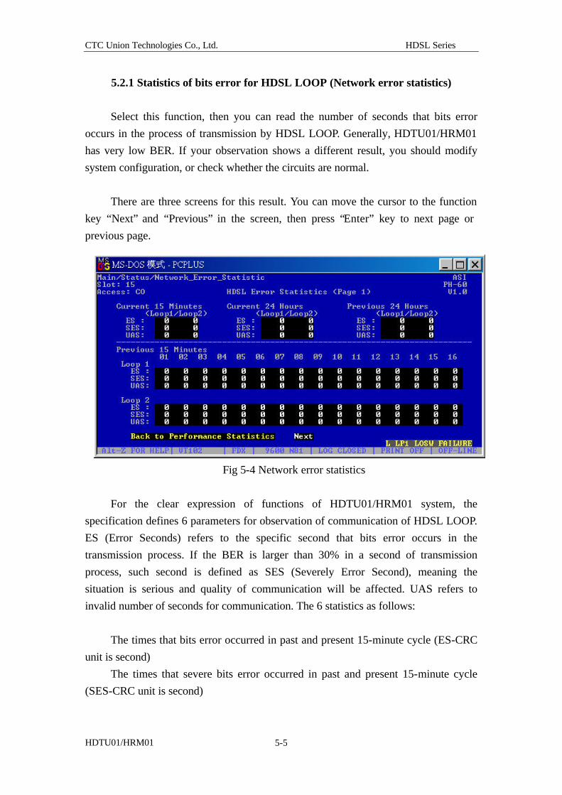
5.2.1 Statistics of bits error for HDSL LOOP (Network error statistics)
Select this function, then you can read the number of seconds that bits error
occurs in the process of transmission by HDSL LOOP. Generally, HDTU01/HRM01
has very low BER. If your observation shows a different result, you should modify
system configuration, or check whether the circuits are normal.
There are three screens for this result. You can move the cursor to the function
key “Next” and “Previous” in the screen, then press “Enter” key to next page or
previous page.
Fig 5-4 Network error statistics
For the clear expression of functions of HDTU01/HRM01 system, the
specification defines 6 parameters for observation of communication of HDSL LOOP.
ES (Error Seconds) refers to the specific second that bits error occurs in the
transmission process. If the BER is larger than 30% in a second of transmission
process, such second is defined as SES (Severely Error Second), meaning the
situation is serious and quality of communication will be affected. UAS refers to
invalid number of seconds for communication. The 6 statistics as follows:
The times that bits error occurred in past and present 15-minute cycle (ES-CRC
unit is second)
The times that severe bits error occurred in past and present 15-minute cycle
(SES-CRC unit is second)
CTC Union Technologies Co., Ltd. HDSL Series
HDTU01/HRM01 5-6
The times that UAS occurred in past and present 15-minute cycle
(UAS unit is second)
The times that bits error occurred in past and present 24-hour cycle
(ES-CRC unit is second)
The times that severe bits error occurred in past and present 24-hour cycle
(SES-CRC unit is second)
The times that UAS occurred in past and present 24-hour cycle
(UAS unit is second)
This statistics report helps you to understand the performance of
HDTU01/HRM01. If the value is higher than that you set up, the system will display
Alarm (warning) message. This function is provided for observation in the COT side
and allows unilateral monitor.
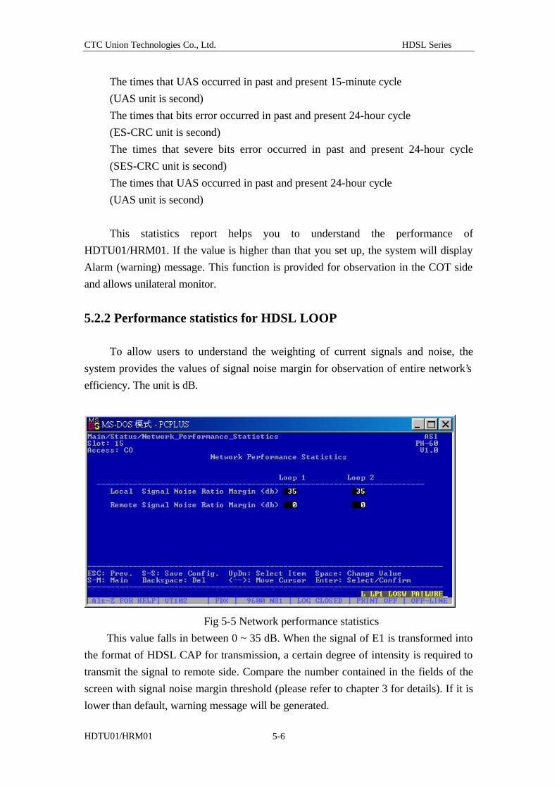
5.2.2 Performance statistics for HDSL LOOP
To allow users to understand the weighting of current signals and noise, the
system provides the values of signal noise margin for observation of entire network’s
efficiency. The unit is dB.
Fig 5-5 Network performance statistics
This value falls in between 0 ~ 35 dB. When the signal of E1 is transformed into
the format of HDSL CAP for transmission, a certain degree of intensity is required to
transmit the signal to remote side. Compare the number contained in the fields of the
screen with signal noise margin threshold (please refer to chapter 3 for details). If it is
lower than default, warning message will be generated.
CTC Union Technologies Co., Ltd. HDSL Series
HDTU01/HRM01 5-7
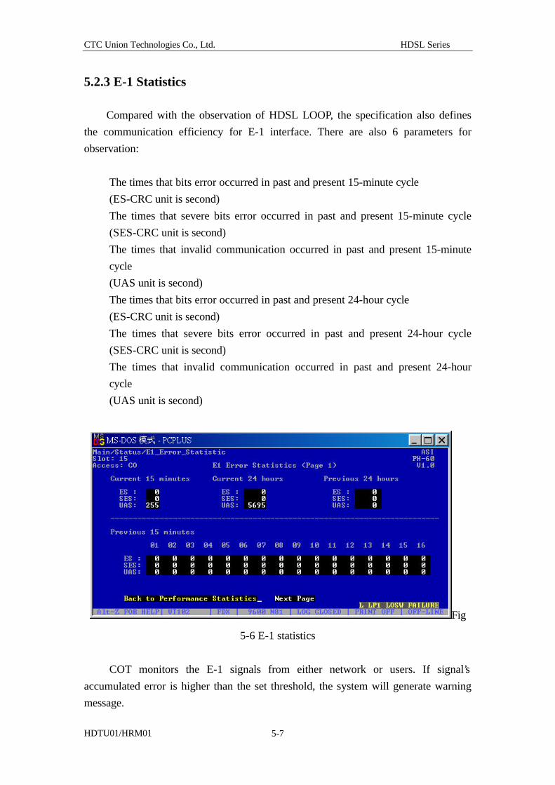
5.2.3 E-1 Statistics
Compared with the observation of HDSL LOOP, the specification also defines
the communication efficiency for E-1 interface. There are also 6 parameters for
observation:
The times that bits error occurred in past and present 15-minute cycle
(ES-CRC unit is second)
The times that severe bits error occurred in past and present 15-minute cycle
(SES-CRC unit is second)
The times that invalid communication occurred in past and present 15-minute
cycle
(UAS unit is second)
The times that bits error occurred in past and present 24-hour cycle
(ES-CRC unit is second)
The times that severe bits error occurred in past and present 24-hour cycle
(SES-CRC unit is second)
The times that invalid communication occurred in past and present 24-hour
cycle
(UAS unit is second)
Fig
5-6 E-1 statistics
COT monitors the E-1 signals from either network or users. If signal’s
accumulated error is higher than the set threshold, the system will generate warning
message.
CTC Union Technologies Co., Ltd. HDSL Series
HDTU01/HRM01 5-8
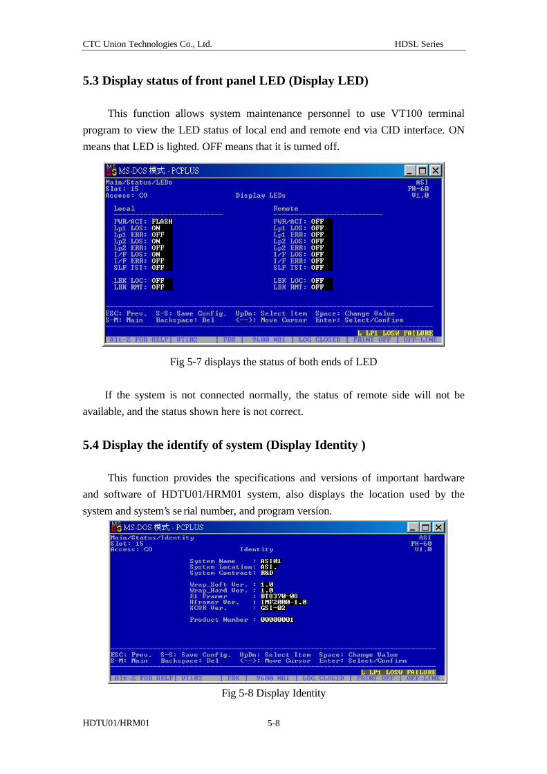
5.3 Display status of front panel LED (Display LED)
This function allows system maintenance personnel to use VT100 terminal
program to view the LED status of local end and remote end via CID interface. ON
means that LED is lighted. OFF means that it is turned off.
Fig 5-7 displays the status of both ends of LED
If the system is not connected normally, the status of remote side will not be
available, and the status shown here is not correct.
5.4 Display the identify of system (Display Identity ) This function provides the specifications and versions of important hardware
and software of HDTU01/HRM01 system, also displays the location used by the
system and system’s se rial number, and program version.
Fig 5-8 Display Identity
CTC Union Technologies Co., Ltd. HDSL Series
HDTU01/HRM01 6-1
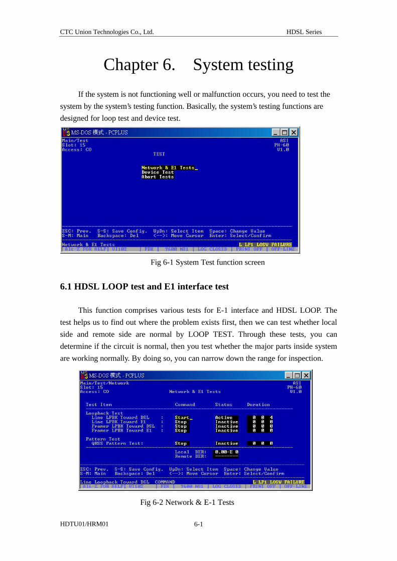
Chapter 6. System testing
If the system is not functioning well or malfunction occurs, you need to test the
system by the system’s testing function. Basically, the system’s testing functions are
designed for loop test and device test.
Fig 6-1 System Test function screen
6.1 HDSL LOOP test and E1 interface test This function comprises various tests for E-1 interface and HDSL LOOP. The
test helps us to find out where the problem exists first, then we can test whether local
side and remote side are normal by LOOP TEST. Through these tests, you can
determine if the circuit is normal, then you test whether the major parts inside system
are working normally. By doing so, you can narrow down the range for inspection.
Fig 6-2 Network & E-1 Tests
CTC Union Technologies Co., Ltd. HDSL Series
HDTU01/HRM01 6-2
When you see the screen of Fig 6-2, you can use the up and down keys to move
the highlight bar to the specified field, then you press Enter key to start executing the
value shown in the specified field, such as “Start” commences testing. You’ll see the
number (length of testing time) changing. The field value of “Start” has changed to
“Stop”. When you press Enter again, the test stops.
There are 5 testing items in Fig 6-2:
l Loopback Tests
1. Line LPBK Toward DSL (for definition of test, please refer to p 2-17)
2. Line LPBK Toward E-1 (for definition of test, please refer to p 2-17)
3. Framer LPBK Toward DSL
(for definition of test, please refer to p 2-17)
4. Framer LPBK Toward E-1 (for definition of test, please refer to p
2-17)
l Pattern Tests
QRSS Pattern Test
QRSS Pattern Tests
The system provides QRSS Pattern Test. When you select QRSS PatternTest
command, the system will send out specific codes. When the remote side receives it,
same code will be sent back. Then the system calculate bit error number and bit error
rate.
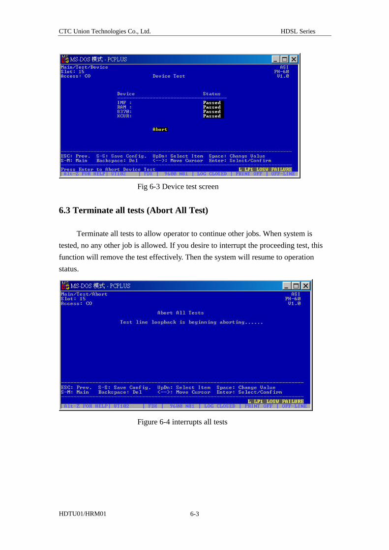
6.2 Test the major components (Device Tests) This command allows system maintenance personnel to observe whether the
major components of HDTU01/HRM01 system are normal. There are 4 major
components can be tested:
l IMF: HDSL Framer
l RAM: the memory used by the system
l 8370: E1 Framer
l XCVR: HDSL LOOP transmission unit
After the test is over, the result appears in the screen¡ D
CTC Union Technologies Co., Ltd. HDSL Series
HDTU01/HRM01 6-3
Fig 6-3 Device test screen
6.3 Terminate all tests (Abort All Test) Terminate all tests to allow operator to continue other jobs. When system is
tested, no any other job is allowed. If you desire to interrupt the proceeding test, this
function will remove the test effectively. Then the system will resume to operation
status.
Figure 6-4 interrupts all tests