Embed Size (px)
Citation preview
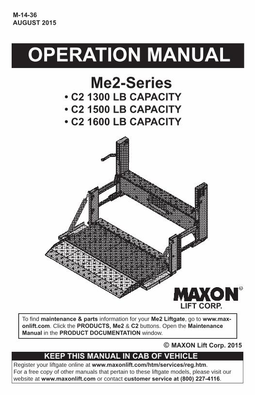
M-14-36AUGUST 2015
LIFT CORP.
© MAXON Lift Corp. 2015
OPERATION MANUALMe2-Series
• C2 1300 LB CAPACITY• C2 1500 LB CAPACITY• C2 1600 LB CAPACITY
To fi nd maintenance & parts information for your Me2 Liftgate, go to www.max-onlift.com. Click the PRODUCTS, Me2 & C2 buttons. Open the Maintenance Manual in the PRODUCT DOCUMENTATION window.
KEEP THIS MANUAL IN CAB OF VEHICLERegister your liftgate online at www.maxonlift.com/htm/services/reg.htm.For a free copy of other manuals that pertain to these liftgate models, please visit our website at www.maxonlift.com or contact customer service at (800) 227-4116.

TABLE OF CONTENTS
WARNINGS ............................................................................ 4
LIFTGATE TERMINOLOGY ................................................... 5
DECALS ................................................................................. 6
FORKLIFT ADVISORY .......................................................... 8
OPERATING INSTRUCTIONS .............................................. 9
ACTIVATING LIFTGATE ......................................................... 9
UNFOLDING THE PLATFORM .............................................. 10
POSITIONING LOAD ............................................................. 13
RAISING & UNLOADING PLATFORM ................................... 14
UNLOADING VEHICLE .......................................................... 15
POSITIONING LOAD ............................................................. 15
LOWERING & UNLOADING PLATFORM .............................. 16
STOWING PLATFORM .......................................................... 17
TURNING OFF POWER ........................................................ 20
4
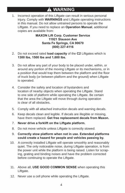
2. Do not exceed rated load capacity of the C2 Liftgates which is 1300 lbs, 1500 lbs and 1,600 lbs.
3. Do not allow any part of your body to be placed under, within, or around any portion of the moving Liftgate or its mechanisms, or in a position that would trap them between the platform and the fl oor of truck body (or between platform and the ground) when Liftgate
is operated.
4. Consider the safety and location of bystanders and location of nearby objects when operating the Liftgate. Stand to one side of platform while operating the Liftgate. Be certain that the area the Liftgate will move through during operation is clear of all obstacles.
5. Comply with all attached instruction decals and warning decals.
11. Above all, USE GOOD COMMON SENSE when operating this Liftgate.
8. Do not move vehicle unless Liftgate is correctly stowed.
6. Keep decals clean and legible. If decals are illegible or missing, have them replaced. Get free replacement decals from Maxon.
7. Never drive a forklift on the Liftgate platform.
10. A correctly installed Liftgate will operate smoothly and reasonably quiet. The only noticeable noise, during Liftgate operation, is from the power unit while the platform is being raised. Listen for scrap-ing, grating and binding noises and have the problem corrected before continuing to operate the Liftgate.
MAXON Lift Corp. Customer Service11921 Slauson Ave
Santa Fe Springs, CA 90670(800) 227-4116
WARNING!
9. Correctly stow platform when not in use. Extended platforms could create a hazard for people and vehicles passing by.
1. Incorrect operation of this Liftgate can result in serious personal injury. Comply with WARNINGS and Liftgate operating instructions in this manual. Do not allow untrained persons to operate the Liftgate. If you need to replace an Operation Manual, additional copies are available from:
12. Never use a cell phone while operating the Liftgate.
WARNINGS
5
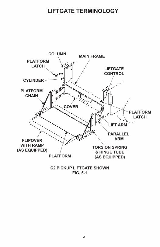
LIFTGATE TERMINOLOGY
FLIPOVER WITH RAMP
(AS EQUIPPED)
COLUMN MAIN FRAME
LIFTGATE CONTROL
COVER
PLATFORM
CYLINDER
PLATFORMCHAIN
TORSION SPRING & HINGE TUBE(AS EQUIPPED)
LIFT ARM
PARALLEL ARM
PLATFORM LATCH
PLATFORM LATCH
C2 PICKUP LIFTGATE SHOWNFIG. 5-1
6
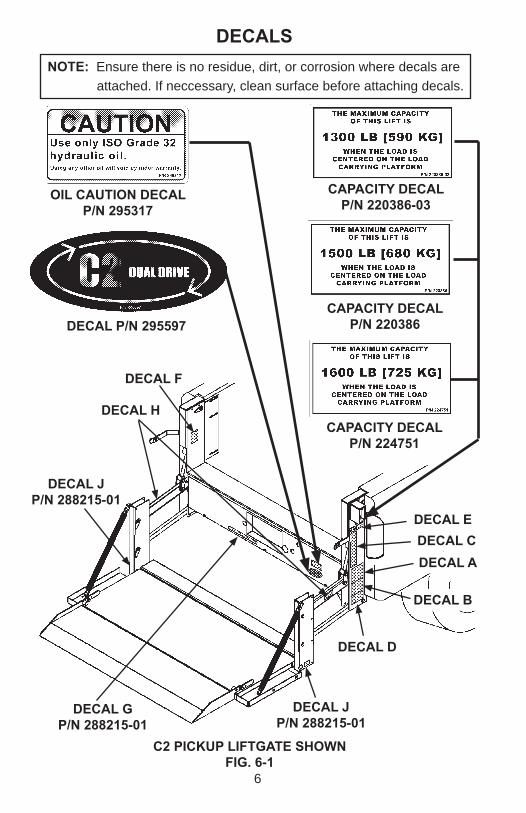
DECALSNOTE: Ensure there is no residue, dirt, or corrosion where decals are
attached. If neccessary, clean surface before attaching decals.
DECAL G P/N 288215-01
DECAL JP/N 288215-01
DECAL H
OIL CAUTION DECALP/N 295317
DECAL A
DECAL B
DECAL E
DECAL JP/N 288215-01
DECAL D
DECAL C
DECAL F
CAPACITY DECALP/N 220386-03
CAPACITY DECALP/N 220386
CAPACITY DECALP/N 224751
DECAL P/N 295597
C2 PICKUP LIFTGATE SHOWNFIG. 6-1
7
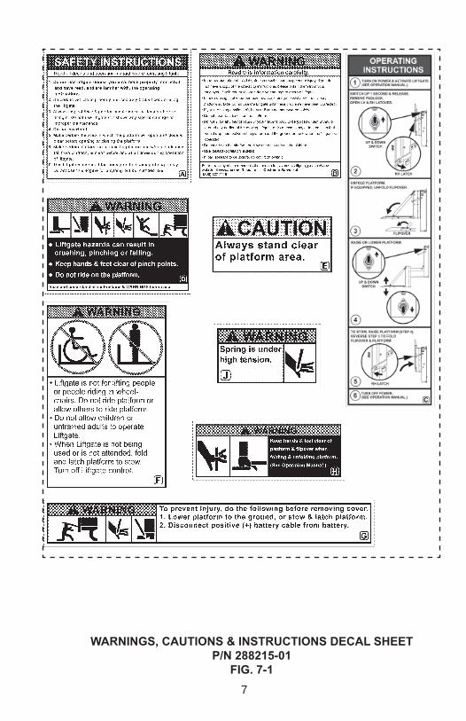
WARNINGS, CAUTIONS & INSTRUCTIONS DECAL SHEET P/N 288215-01
FIG. 7-1
8
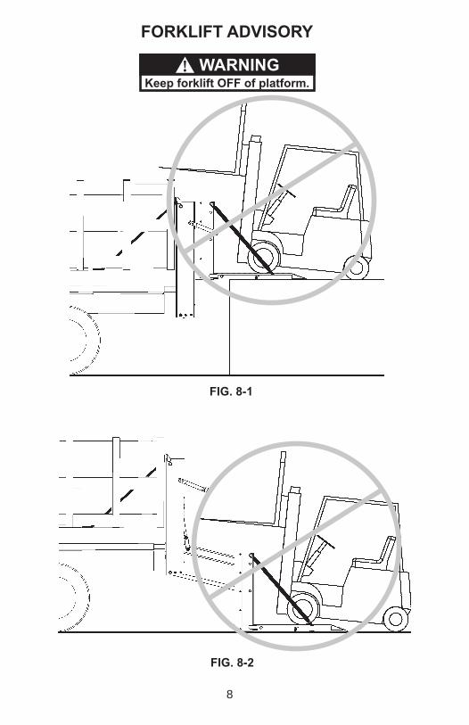
FORKLIFT ADVISORY
FIG. 8-1
FIG. 8-2
Keep forklift OFF of platform.WARNING!
9
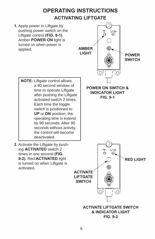
POWER ON SWITCH & INDICATOR LIGHT
FIG. 9-1
ACTIVATING LIFTGATE1. Apply power to Liftgate by
pushing power switch on the Liftgate control (FIG. 9-1). Amber POWER ON light is turned on when power is applied.
2. Activate the Liftgate by push-ing ACTIVATED switch 2 times in one second (FIG. 9-2). Red ACTIVATED light is turned on when Liftgate is activated.
POWER SWITCH
AMBER LIGHT
ACTIVATE LIFTGATE SWITCH
RED LIGHT
ACTIVATE LIFTGATE SWITCH & INDICATOR LIGHT
FIG. 9-2
NOTE: Liftgate control allows a 90 second window of time to operate Liftgate after pushing the Liftgate activated switch 2 times. Each time the toggle switch is positioned to UP or DN position, the operating time is extend by 90 seconds. After 90 seconds without activity, the control will become deactivated.
OPERATING INSTRUCTIONS
10
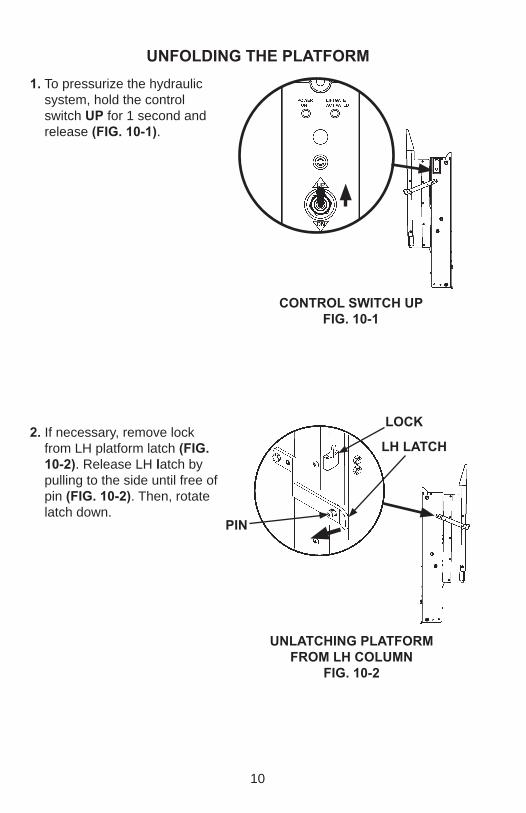
UNFOLDING THE PLATFORM
UNLATCHING PLATFORM FROM LH COLUMN
FIG. 10-2
PIN
1. To pressurize the hydraulic system, hold the control switch UP for 1 second and release (FIG. 10-1).
2. If necessary, remove lock from LH platform latch (FIG. 10-2). Release LH latch by pulling to the side until free of pin (FIG. 10-2). Then, rotate latch down.
CONTROL SWITCH UPFIG. 10-1
LH LATCH
LOCK
11
Never operate control switch or stand in the path of platform while unfolding the platform.
WARNING!
PIN
RH LATCH
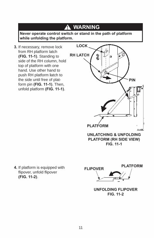
3. If necessary, remove lock from RH platform latch (FIG. 11-1). Standing to side of the RH column, hold top of platform with one hand. Use other hand to push RH platform latch to the side until free of plat-form pin (FIG. 11-1). Then, unfold platform (FIG. 11-1).
PLATFORM
LOCK
UNLATCHING & UNFOLDING PLATFORM (RH SIDE VIEW)
FIG. 11-1
4. If platform is equipped with fl ipover, unfold fl ipover (FIG. 11-2).
UNFOLDING FLIPOVER FIG. 11-2
FLIPOVERPLATFORM
12
UNFOLDING THE PLATFORM - Continued
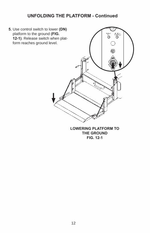
5. Use control switch to lower (DN) platform to the ground (FIG. 12-1). Release switch when plat-form reaches ground level.
LOWERING PLATFORM TOTHE GROUND
FIG. 12-1
13
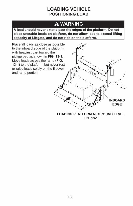
Place all loads as close as possible to the inboard edge of the platform with heaviest part toward the pickup bed as shown in FIG. 13-1. Move loads across the ramp (FIG. 13-1) to the platform, but never rest or raise loads solely on the fl ipover and ramp portion.
A load should never extend past the edges of the platform. Do not place unstable loads on platform, do not allow load to exceed lifting capacity of Liftgate, and do not ride on the platform.
WARNING!
INBOARD EDGE
LOADING PLATFORM AT GROUND LEVELFIG. 13-1
POSITIONING LOADLOADING VEHICLE
14
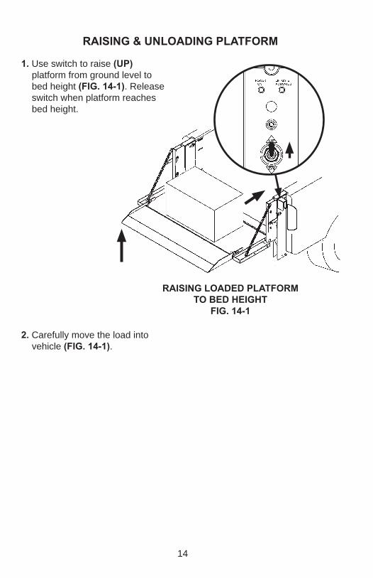
2. Carefully move the load into vehicle (FIG. 14-1).
RAISING & UNLOADING PLATFORM
RAISING LOADED PLATFORM TO BED HEIGHT
FIG. 14-1
1. Use switch to raise (UP) platform from ground level to bed height (FIG. 14-1). Release switch when platform reaches bed height.

15
UNLOADING VEHICLE
INBOARDEDGE
POSITIONING LOAD
MOVING LOAD ON PLATFORMFIG. 15-1
Pulling the load from vehicle to platform can result in a fall from platform and serious injury. When unloading vehicle, always push the load out on the platform.
! WARNING
Unload the vehicle at bed lev-el (FIG. 15-1) as follows. Push load out of the vehicle to cor-rect position on the platform. Place all loads as close as possible to the inboard edge of the platform with heaviest part toward the vehicle body as shown in FIG. 15-1.
A load should never extend past the edges of the platform. Do not place unstable loads on platform, do not allow load to exceed lifting capacity of Liftgate, and do not ride on the platform.
WARNING!
16
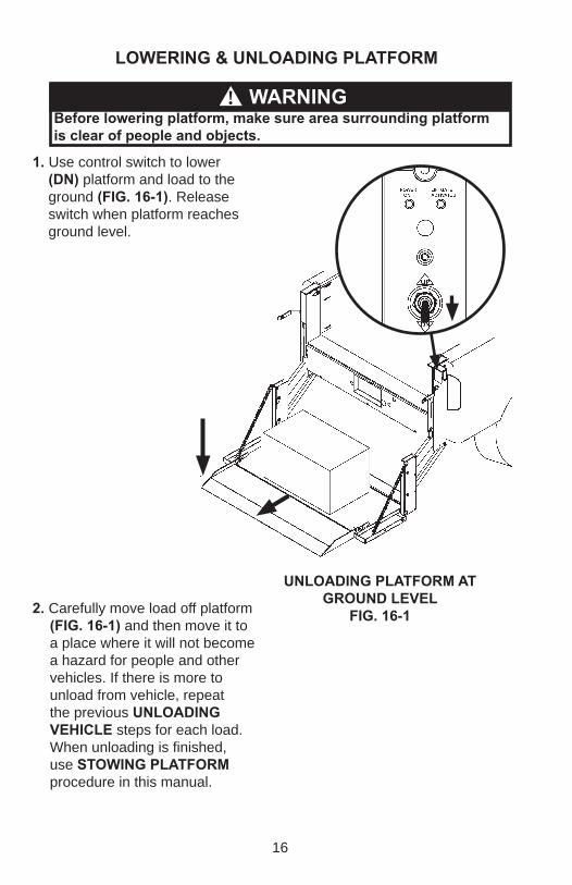
Before lowering platform, make sure area surrounding platform is clear of people and objects.
WARNING!
LOWERING & UNLOADING PLATFORM
UNLOADING PLATFORM AT GROUND LEVEL
FIG. 16-12. Carefully move load off platform (FIG. 16-1) and then move it to a place where it will not become a hazard for people and other vehicles. If there is more to unload from vehicle, repeat the previous UNLOADING VEHICLE steps for each load. When unloading is fi nished, use STOWING PLATFORM procedure in this manual.
1. Use control switch to lower (DN) platform and load to the ground (FIG. 16-1). Release switch when platform reaches ground level.
17
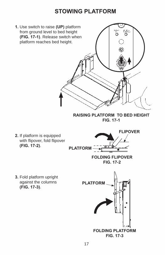
STOWING PLATFORM
RAISING PLATFORM TO BED HEIGHTFIG. 17-1
1. Use switch to raise (UP) platform from ground level to bed height (FIG. 17-1). Release switch when platform reaches bed height.
3. Fold platform upright against the columns (FIG. 17-3).
FOLDING PLATFORMFIG. 17-3
PLATFORM
2. If platform is equipped with fl ipover, fold fl ipover (FIG. 17-2).
FOLDING FLIPOVERFIG. 17-2
FLIPOVER
PLATFORM
18
LATCHING PLATFORM TO RH COLUMN
FIG. 18-1
PIN
LATCHING PLATFORM TO LH COLUMN
FIG. 18-2
LATCH
LATCH
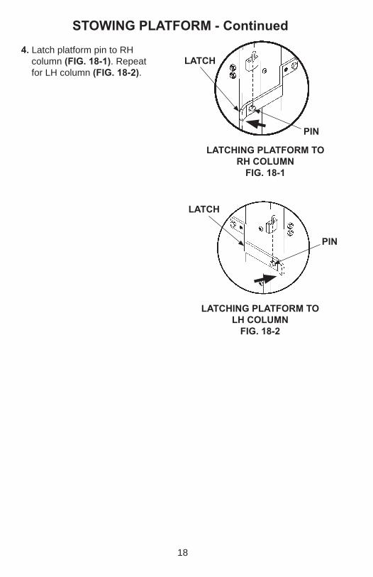
STOWING PLATFORM - Continued4. Latch platform pin to RH
column (FIG. 18-1). Repeat for LH column (FIG. 18-2).
PIN
19
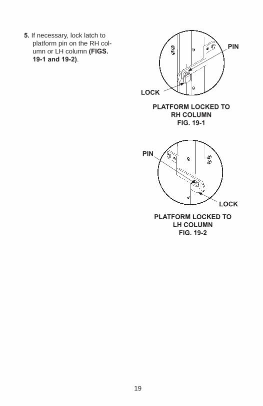
5. If necessary, lock latch to platform pin on the RH col-umn or LH column (FIGS. 19-1 and 19-2).
PLATFORM LOCKED TO RH COLUMN
FIG. 19-1
PIN
PLATFORM LOCKED TO LH COLUMN
FIG. 19-2
PIN
LOCK
LOCK
20
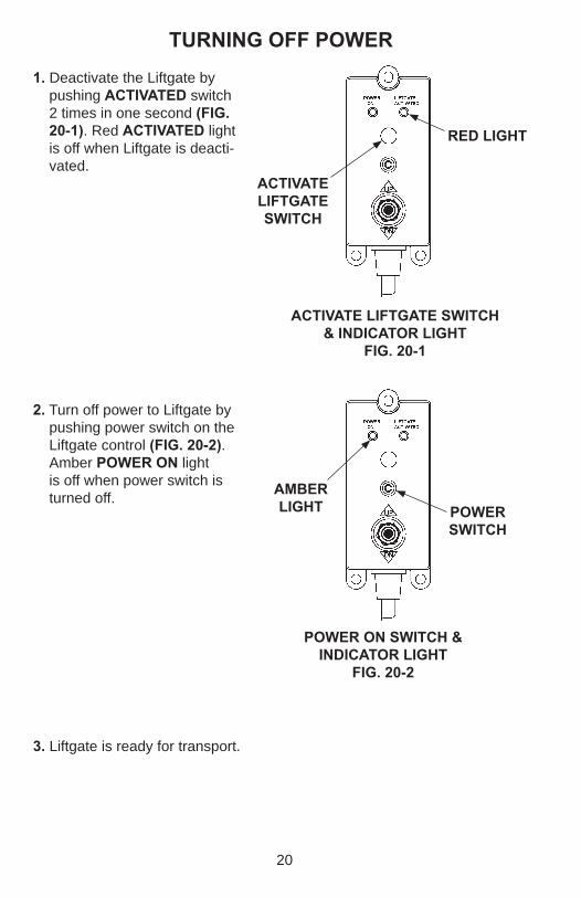
3. Liftgate is ready for transport.
POWER ON SWITCH & INDICATOR LIGHT
FIG. 20-2
TURNING OFF POWER
2. Turn off power to Liftgate by pushing power switch on the Liftgate control (FIG. 20-2). Amber POWER ON light is off when power switch is turned off.
1. Deactivate the Liftgate by pushing ACTIVATED switch 2 times in one second (FIG. 20-1). Red ACTIVATED light is off when Liftgate is deacti-vated.
POWER SWITCH
AMBER LIGHT
ACTIVATE LIFTGATE SWITCH
RED LIGHT
ACTIVATE LIFTGATE SWITCH & INDICATOR LIGHT
FIG. 20-1